DESIGN OF CONTROL SYSTEMS FOR A QUADROTOR FLIGHT VEHICLE EQUIPPED WITH INERTIAL SENSORS A MASTER’S THESIS in Mechatronics Engineering Atılım University by ARDA ÖZGÜR KIVRAK DECEMBER 2006

Welcome message from author
This document is posted to help you gain knowledge. Please leave a comment to let me know what you think about it! Share it to your friends and learn new things together.
Transcript
DESIGN OF CONTROL SYSTEMS FOR A QUADROTOR
FLIGHT VEHICLE EQUIPPED WITH INERTIAL SENSORS
A MASTER’S THESIS
in
Mechatronics Engineering
Atılım University
by
ARDA ÖZGÜR KIVRAK
DECEMBER 2006

ii
DESIGN OF CONTROL SYSTEMS FOR A QUADROTOR
FLIGHT VEHICLE EQUIPPED WITH INERTIAL SENSORS
A THESIS SUBMITTED TO
THE GRADUATE SCHOOL OF NATURAL AND APPLIED SCIENCES
OF
ATILIM UNIVERSITY
BY
ARDA ÖZGÜR KIVRAK
IN PARTIAL FULFILLMENT OF THE REQUIREMENTS FOR THE DEGREE OF
MASTER OF SCIENCE
IN
THE DEPARTMENT OF MECHATRONICS ENGINEERING
DECEMBER 2006

iii
Approval of the Graduate School of (Name of the Graduate School)
_____________________
(Title and Name)
Director
I certify that this thesis satisfies all the requirements as a thesis for the degree of Master of Science/Arts.
_____________________
(Title and Name)
Head of Department
This is to certify that we have read this thesis and that in our opinion it is fully adequate, in scope and quality, as a thesis for the degree of Master of Science/Arts.
_____________________ _____________________
(Title and Name) (Title and Name)
Co-Supervisor Supervisor
Examining Committee Members
Asst.Prof.Dr.Bülent İRFANOĞLU _____________________
Prof.Dr.Abdülkadir ERDEN _____________________
Asst.Prof.Dr.Hakan TORA _____________________
Asst.Prof.Dr.Serhat ERPOLAT _____________________
Instr. Kutluk Bilge ARIKAN _____________________

iv
ABSTRACT
DESIGN OF CONTROL SYSTEMS FOR A QUADROTOR FLIGHT
VEHICLE EQUIPPED WITH INERTIAL SENSORS
Kıvrak, Arda Özgür
M.S. Mechatronics Engineering Department
Supervisor: Kutluk Bilge Arıkan
December 2006 104 pages
This thesis reviews the Design of Control Systems for a Quadrotor Flight Vehicle
Equipped with Inertial Sensors in detail. The control system is developed in
Matlab/Simulink and real time implementation is achieved by using Simulink Real
Time Windows Target utility. Linear Quadratic Regulator is designed for the
stabilization of the attitude and shown to work in real time. The hardware consists of
the data acquisition card, DC motor drivers, sensor set, the DC motors, and the
DraganFlyer V Ti structure.
Keywords: Control, Quadrotor platform, Inertial Sensors, Matlab/Simulink, Real
Time Windows Target (RTWT), Real Time Control, Linear Quadratic regulator.

v
ÖZ
ATALETSEL ALGILAYICILARA SAHİP DÖRT MOTORLU UÇUŞ ARACI
İÇİN DENETİM SİSTEMLERİ TASARIMI
Kıvrak, Arda Özgür
Yüksek Lisans, Mekatronik Mühendisliği Bölümü
Tez Yöneticisi: Kutluk Bilge Arıkan
Aralık 2006, 104 sayfa
Bu calışma, dört motorlu uçuş aracının denetim sistemlerini incelemekte ve
detayı ile vermektedir. Denetim sistemi Matlab/Simulink ortamında geliştirilmiş ve
Simulink Real Time Windows Target kullanılarak gerçek zamanlı uygulaması
yapılmıştır. Sistemin yönelim kararlılığının denetimi için Lineer Quadratik Regülatör
tasarlanmış ve donanımlı sistemle gerçek zamanlı çalıştırılması gösterilmiştir.
Donanım veri toplama kartı, doğru akım motor sürücü devresi, algılayıcı seti, doğru
akım motorları ve DraganFlyer V Ti gövdesinden oluşmaktadır.
Anahtar Kelimeler: Denetim, Dört motorlu platform, Matlab/Simulink, Real Time
Windows Target (RTWT), Gerçek zamanlı denetim, Lineer Quadratik Regülatör.

vi
To My Parents

vii
ACKNOWLEDGMENTS
I express sincere appreciation to my supervisor Kutluk Bilge Arıkan and Bülent
Irfanoğlu for their guidance and insight throughout the research. And to my family, I
offer sincere thanks for their continuous support and patience during this period.

viii
TABLE OF CONTENTS
ABSTRACT............................................................................................................... IV
ÖZ ............................................................................................................................... V
TABLE OF CONTENTS........................................................................................ VIII
LIST OF TABLES ...................................................................................................... X
LIST OF FIGURES ...................................................................................................XI
CHAPTER
1.INTRODUCTION............................................................................................... 1
1.1 Aim and Scope ........................................................................................ 2
1.2 Layout of the Dissertation....................................................................... 3
2. LITERATURE SURVEY ABOUT QUAD-ROTOR SYSTEMS..................... 4
2.1 Designs in Literature ............................................................................... 4
2.1.1 European Aeronautic Defense and Space Company .................... 5
2.1.2 Pennsylvania State University...................................................... 5
2.1.3 Middle East Technical University ................................................ 7
2.1.4 Australian National University..................................................... 7
2.1.5 University of British Columbia Vancouver, BC, Canada ............ 8
2.1.6 Cornell University ...................................................................... 10
2.1.7 Swiss Federal Institute of Technology ....................................... 10
2.1.8 University of Technology in Compiegne, France ...................... 12
2.1.9 Stanford University .................................................................... 13
2.1.10 Australian National University, Canberra, Australia ............... 14
2.2 Applied Control Systems ...................................................................... 15
2.3 Employed Sensors................................................................................. 16
3. MATHEMATICAL MODEL OF THE HOVERING PLATFORM............... 17
3.1 Assumptions of the Model .................................................................... 17
3.2 Derivation of the State Equations ......................................................... 18
3.3 Motor-Propeller Models........................................................................ 22
3.4 Linearization of the Nonlinear State Equations .................................... 27
4. LQR DESIGN FOR ATTITUDE STABILIZATION ..................................... 30
4.1 Linear Quadratic Regulator................................................................... 30

ix
5. STRUCTURE AND TEST BENCH................................................................ 34
5.1 The Frame of the Quadrotor.................................................................. 34
5.2 Sensors Used in the System .................................................................. 34
5.2.1 Accelerometer............................................................................. 36
5.2.2 Gyroscopes ................................................................................. 38
5.2.3 Magnetometer............................................................................. 39
5.3 Drivers................................................................................................... 41
5.4 Proposed Driver Circuitry ..................................................................... 43
5.5 Power Supplies...................................................................................... 48
5.6 Driver Test Results................................................................................ 49
5.7 Test Bench............................................................................................. 51
6. REAL TIME CONTROL IMPLEMENTATION............................................ 54
6.1 The Control Software............................................................................ 54
7. TESTS AND RESULTS.................................................................................. 61
7.1 Eliminating Sensor Noise...................................................................... 61
8. DISCUSSIONS AND CONCLUSIONS ......................................................... 68
REFERENCES........................................................................................................... 70
APPENDICES
1.CONTROLLABILITY AND OBSERVABILTY MATRIX ........................... 74
2.MOTOR DATASHEET.................................................................................... 76
3.SENSOR DATASHEETS................................................................................. 78

x
LIST OF TABLES
TABLE
Table 1 Inertial Parameters ........................................................................................ 26
Table 2 Available Sensors.......................................................................................... 35
Table 3 Calibration constants (at room temperature ~200) ........................................ 57
Table 4 Mabuchi motor specs. ................................................................................... 76
Table 5 IRFZ44N specs. ............................................................................................ 77

xi
LIST OF FIGURES
FIGURES
Figure 1 Mesicopter ..................................................................................................... 4
Figure 2 DraganFlyer ................................................................................................... 4
Figure 3 Quattrocopter ................................................................................................. 5
Figure 4 Quadrotor designed in Pennsylvania State University .................................. 6
Figure 5 Quadrotor tracking with a camera ................................................................. 6
Figure 6 Quadrotor designed in Middle East Technical University, Turkey............... 7
Figure 7 The X4-Flyer developed in FEIT, ANU........................................................ 8
Figure 8 Setup developed in Department of Electrical and Computer Engineering
University of British Columbia Vancouver, BC, Canada .................................... 9
Figure 9 Quadrotor designed in Cornell University................................................... 10
Figure 10 Quadrotor designed in Swiss Federal Institude of Technology................. 11
Figure 11 Quadrotor designed in University of Technology in Compiegne, France. 12
Figure 12 Quadrotor designed in Stanford University............................................... 14
Figure 13 X-4 Flyer Mark II. ..................................................................................... 15
Figure 14 All of the States (b stands for body and e stands for earth)....................... 17
Figure 15 Motor test setup for thrust calculation. ...................................................... 23
Figure 16 Test results of the 1st Motor (voltage vs. thrust(T))................................... 23
Figure 17 Test results of the 2nd motor (voltage vs. thrust(T)) .................................. 24
Figure 18 Test results of the 3rd motor (voltage vs. thrust(T))................................... 24
Figure 19 Test results of the 4th motor (voltage vs. thrust(T))................................... 24
Figure 20 The LQR system for nonlinear and linear state-space models ................. 32
Figure 21 Comparison of the nonlinear and state space models for a 0.1 rad
disturbance in yaw angle (continuous line represents the State space model and
dashed line represents nonlinear model) ............................................................ 33
Figure 22 (a) Accelerometer (Analog devices) (b) Magnetometer (Honeywell) (c)
Accelerometer (Memsic) (d) Gyroscope (Murata) (e) Compass Module
(Parallax) (f) Gyroscope (Silicon sensing) (g) Gyroscope (Silicon Sensing) .... 35
Figure 23 Accelerometer (ruler is in centimeters) ..................................................... 37
Figure 24 ADXL203EB accelerometer evaluation board.......................................... 37
Figure 25 A picture of the gyroscope evaluation board ADXRS150EB ................... 39

xii
Figure 26 Magnetometer at the lower left corner and three gyros at the back of it
(magnetometer shown with an arrow) ............................................................... 40
Figure 27 Circuit diagram of the gyro hardware........................................................ 40
Figure 28 IRFZ44N n-channel Mosfet transistor schematic for motor drivers ......... 41
Figure 29 Mosfet IRLZ44N driven in switching mode [34]...................................... 41
Figure 30 ASTRO 204D speed controller.................................................................. 43
Figure 31 Driver system block diagram..................................................................... 44
Figure 32 Terminal board........................................................................................... 44
Figure 33 The Block diagram for the data acquisition card terminal board .............. 45
Figure 34 A view of the hardware system ................................................................. 45
Figure 35 Voltage to 5 V PWM converter ................................................................. 46
Figure 36 Mosfet gate driving optocouplers (TLP250) ............................................. 46
Figure 37 Electronic Hardware .................................................................................. 47
Figure 38 By-pass capacitor for high reverse inductive voltages .............................. 48
Figure 39 Agilient 15 A / 35 V Power supply ........................................................... 48
Figure 40 Power supply for the sensor set ................................................................. 49
Figure 41 emergency button....................................................................................... 49
Figure 42 PWM driven Mabuchi motor’s RMS voltage............................................ 50
Figure 43 Assembled Quadrotor ................................................................................ 51
Figure 44 Cable connection ....................................................................................... 52
Figure 45 Side sways ................................................................................................. 52
Figure 46 The kneecap or spherical joint................................................................... 52
Figure 47 Experimental setup .................................................................................... 53
Figure 48 The hole at the centre of PCB................................................................... 53
Figure 49 Simulink blocks for one motor .................................................................. 55
Figure 50 A Sample Gyro Block................................................................................ 56
Figure 51 A sample accelerometer block................................................................... 57
Figure 52 A sample magnetometer block .................................................................. 57
Figure 53 The Control Blocks in Simulink................................................................ 59
Figure 54 Hardware in the Loop System ................................................................... 60
Figure 55 Unfiltered sensor output for roll angle....................................................... 61
Figure 56 Filtered Roll angle measurement with a 8th order Butterworth lowpass
filter with 10 Hz bandwidth ............................................................................... 62
Figure 57 Unfiltered sensor output for pitch angle .................................................... 62

xiii
Figure 58 Filtered pitch angle with a 8th order Butterworth lowpass filter with 10 Hz
bandwidth........................................................................................................... 63
Figure 59 yaw rate unfiltered (only factory-set filter on the sensor) sensor output... 63
Figure 60 pitch rate unfiltered (only factory-set filter on the sensor) sensor output.. 64
Figure 61 roll rate unfiltered (only factory-set filter on the sensor) sensor output .... 64
Figure 62 Three spikes in the accelerometer signal (one at the top and two at the
bottom) ............................................................................................................... 65
Figure 63 LQR control of pitch rate with a disturbance ............................................ 66
Figure 64 LQR control of roll rate with a disturbance............................................... 67
Figure 65 LQR control of yaw rate with a disturbance.............................................. 67

xiv
LIST OF ABBREVIATIONS
UAV – Unmanned Aerial Vehicle
MEMS – Micro Electromechanical Systems
INS – Inertial Navigation System
LQR – Linear Quadratic Regulator
EKF – Extended Kalman Filter
VTOL – Vertical Take Off and Landing
GPS – Global Positioning System
PHB – Popov, Hautus and Belevitch PWM – Pulse Width Modulation EADS – European Aeronautic Defense and Space Company FEIT – Faculty of Engineering and Information Technology ANU – Australian National University STARMAC – Stanford Testbed of Autonomous Rotorcraft for Multi-Agent Control A.M. – Amplitude Modulation

xv
LIST OF SYMBOLS
p – pitch angular rate
q – roll angular rate
r – yaw angular rate
φ − pitch angle
θ − roll angle
ψ − yaw angle
x – position along x axis
y – position along y axis
z – position along z axis
u – linear speed along body x axis
v – linear speed along body y axis
w – linear speed along body z axis
Ix – The inertia around the x axis
Iy – The inertia around the y axis
Iz – The inertia around the z axis

1
CHAPTER 1
1.INTRODUCTION
Today, unmanned aerial vehicles (UAVs) are an important part of scientific study
both in military and space studies. As a substitute for human piloted vehicles they are
advantageous to protect human life in multiple dangerous environments. Their
reliabilities in tough circumstances are much higher than their counter parts.
In this work the effort to produce quadrotor unmanned aerial vehicles (UAVs) at the
Robotics Laboratory is presented. The main purpose of this study is to explore
control methodologies for quadrotor unmanned aerial vehicles (UAVs).
Fixed-wing vehicles have long-range since they are energy efficient, but they lack
the maneuverability required for many UAV tasks. For example, Blimps are easy to
control when there are fewer disturbances like wind, and lift comes from natural
buoyancy, but their maneuverability is limited. The helicopters have advantages over
conventional fixed-wing aircraft and blimps on surveillance and inspection tasks,
since they can take-off and land in limited space and can easily hover above targets.
Moreover, helicopters have the advantage of maneuverability. Unfortunately, this
advantage makes helicopters very hard to control, requiring sophisticated sensors and
fast on-board computation [6].
The design of unmanned aerial vehicles involves the integration of various steps such
as design, selection of sensors and developing controllers. These steps can not be
treated separately. For example, one can not design a vehicle without considering the
sensory input or the controllers that will be implemented, as these steps are closely
related to each other [6].
In order to create an autonomous UAV, precise knowledge of the helicopter position
and orientation is needed. This information can be obtained from Inertial Navigation

2
Systems (INS), Global Positioning Systems (GPS) or other sensors like sonar sensor.
Typically, multiple sensors are used to overcome limitations of individual sensors,
thereby increasing the reliability and decreasing the errors. Vision sensors are
primarily used for estimating the relative positions of some target, like a landing site
or a ground vehicle. Unfortunately the vision system is not as fast as a gyro, and it is
not as reliable as other sensors due to sensitivity to changes in lighting conditions.
Our primary goal is to investigate the possibility of a real time working controller.
Limited payload capacity may not permit the use of heavy navigation systems [6].
As a test bed a remote-controlled, model helicopter (Draganflyer V Ti) selected.
A Quadrotor is a four-rotor helicopter. It is an under-actuated, dynamic vehicle with
four input forces and six degrees of freedom. Unlike regular helicopters that have
variable pitch angle rotors, a quadrotor helicopter has four fixed-pitch angle rotors.
The basic motions of a Quadrotor are generated by varying the rotor speeds of all
four rotors, thereby changing the lift forces. The helicopter tilts towards the direction
of the slow spinning rotor, which enables acceleration along that direction.
Therefore, control of the tilt angles and the motion of the helicopter are closely
related and estimation of orientation (roll and pitch) is critical. Spinning directions of
the rotors are set to balance the moments and eliminate the need for a tail rotor. This
principle is also used to produce the desired yaw motions. A good controller should
properly arrange the speed of each rotor so that only the desired states change.
1.1 Aim and Scope
In this study, it is desired to construct a nonlinear model of quadrotor in Simulink. It
is aimed to design control algorithms that can stabilize the attitude based on the
linearized model around hovering conditions and to implement the controller on
physical platform using Simulink RTWT, PC and data acquisition card.

3
1.2 Layout of the Dissertation Chapter 2 is the literature survey, which introduces some of the work that has been
done on design, and control of flying vehicles. This chapter will also provide some
background on sensors. Acceleration sensors, gyros and magnetometers are the
sensors used in this work. Chapter 3 includes the derivations of the mathematical
equations of the system. In Chapter 4 the LQR design for attitude stabilization is
discussed. Chapter 5 explains the work about the structure and test bench. Real time
controller implementation is discussed in chapter 6. Chapter 7 summarizes the tests
and their results. And the final part chapter 8 is the conclusion of this study.

4
CHAPTER 2
2. LITERATURE SURVEY ABOUT QUAD-ROTOR SYSTEMS
2.1 Designs in Literature
In 1907, the Breguet Brothers constructed the first quad-rotor named Gyroplane No.
1 [1]. The flight was a good work to show the principle of a quadrotor. In 1922,
Georges de Bothezat built a quadrotor with a rotor located at each end of a truss
structure of intersecting beams, placed in the shape of a cross [1]. Experimental
aircrafts X-19 and Bell X-22A are also designed as quad-tilt rotor aircrafts [1].
In time due to the tremendous improvements in manufacturing techniques and
innovations in metallurgical material knowledge more precise and smaller sensors
can now be produced. The Microelectromechanical Systems (MEMs) technology
now allows the production of machine components such as gears with sizes in 10-6
meter range [15] [30]. Using this MEMS technology very small accelerometers,
gyros and magnetometers are also produced [24] [25] [26] [27] [28], which caused
the production of smaller strapdown inertial navigation systems. As a result of this
improvement in technology very small quadrotors are developed around the world
such as Mesicopter (Figure 1) [6] and Hoverbot [6]. There is also commercially
available quadrotor named DraganFlyer (Figure 2)
Figure 1 Mesicopter
Figure 2 DraganFlyer
5
Recently, there are several different studies in the literature about quadrotors. These
works utilized different controllers, equipments and materials.
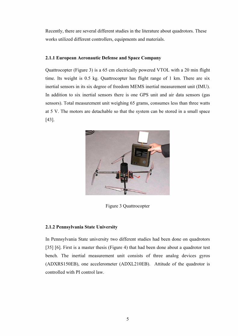
2.1.1 European Aeronautic Defense and Space Company Quattrocopter (Figure 3) is a 65 cm electrically powered VTOL with a 20 min flight
time. Its weight is 0.5 kg. Quattrocopter has flight range of 1 km. There are six
inertial sensors in its six degree of freedom MEMS inertial measurement unit (IMU).
In addition to six inertial sensors there is one GPS unit and air data sensors (gas
sensors). Total measurement unit weighing 65 grams, consumes less than three watts
at 5 V. The motors are detachable so that the system can be stored in a small space
[43].
Figure 3 Quattrocopter
2.1.2 Pennsylvania State University In Pennsylvania State university two different studies had been done on quadrotors
[35] [6]. First is a master thesis (Figure 4) that had been done about a quadrotor test
bench. The inertial measurement unit consists of three analog devices gyros
(ADXRS150EB), one accelerometer (ADXL210EB). Attitude of the quadrotor is
controlled with PI control law.

6
Figure 4 Quadrotor designed in Pennsylvania State University
Second work done in university of Pennsylvania (Figure 5) utilizes DraganFlyer as a
testbed. It has external pan-tilt ground and on-board cameras in addition to the three
onboard gyroscopes. One camera placed on the ground captures the motion of five
2.5 cm colored markers present underneath the DraganFlyer, to obtain pitch, roll and
yaw angles and the position of the quadrotor by utilizing a tracking algorithm and a
conversion routine. In other words, two-camera method has been introduced for
estimating the full six degrees of freedom (DOF) pose of the helicopter. Algorithm
routines ran in an off board computer. Due to the weight limitations GPS or other
accelerometers could not be add on the system. The controller obtained the relative
positions and velocities from the cameras only.
Two methods of control are studied – one using a series of mode-based, feedback
linearizing controllers and the other using a back-stepping control law. The
helicopter was restricted with a tether to vertical, yaw motions and limited x and y
translations. Simulations performed on MATLAB-Simulink show the ability of the
controller to perform output tracking control even when there are errors on state
estimates.
Figure 5 Quadrotor tracking with a camera

7
2.1.3 Middle East Technical University Three orthogonal piezoelectric gyro used in the system designed in Middle East
Technical University (Figure 6) to control the attitude of the quadrotor [32]. The
attitude controlled with a Linear Quadratic Regulator and PD controller. Frame
consists of 45 cm rectangular aluminum profiles.
Figure 6 Quadrotor designed in Middle East Technical University, Turkey
2.1.4 Australian National University
The X4-Flyer developed in ANU [14] consists of a HC-12 a single board computer,
developed at QCAT that was used as the signal conditioning system. This card uses
two HC-12 processors and outputs PWM signals that control the speed drivers
directly, inputs PWM signals from an R700 JR Slimline RC receiver allowing direct
plot input from a JP 3810 radio transmitter and has two separate RS232 serial
channels, the first used to interface with the inertial measurement unit (IMU) and
second used as an asynchronous data linked to the ground based computer.
As an IMU the most suitable unit considered was the EiMU embedded inertial
measurement unit developed by the robotics group in QCAT, CSIRO weighs 50-
100g. Crossbow DMU-6 is also used in the prototype. It weighs 475g.

8
The rotor used is an 11’’ diameter APC-C2 2.9:1 gear system included 6’’ per
revolution pitch with a maximum trust of 700grams. An the motors are Johnson 683
500 series motors
The speed controller used is MSC30 B with a weight 26g rated 30A at 12V
The pilot augmentation control system is used. A double lead compensator is used
for the inner loop. The final setup is shown in Figure 7.
Figure 7 The X4-Flyer developed in FEIT, ANU
2.1.5 University of British Columbia Vancouver, BC, Canada Setup developed in Department of Electrical and Computer Engineering University
of British Columbia Vancouver, BC, Canada [4]. This work focused on the nonlinear
modelling of a quad rotor UAV. An experimental system including a flying mill, a
DSP system, a programmed microprocessor and a wireless transmitter have been
used to test the flight controller. Based on the nonlinear model, an H∞ loop shaping
controller is designed for stabilization, speed, throttle and yaw control.
A microprocessor, PIC16F877, is programmed to transfer the control data to a pulse
width modulated signal in order to reduce significant CPU load which otherwise

9
would have been associated with the DS1102. This signal is further used to control
the four rotors of the Draganflyer III via a 4 channel Futaba radio transmitter
working in training mode.
In order to carry out flight control experiments, an experimental rig including a
custom designed flying mill, a personal computer, dSPACE DSP board, a
microprocessor pulse modulator, a radio transmitter and the Draganflyer III was
built. A picture of the flying mill is shown in Figure 8. The steel base and carbon
fiber boom limit the flight route of the UAV Draganflyer III to a half sphericity of 1
meter radius.
Based on the nonlinear model, an H∞ loop shaping controller is designed for
stabilization, speed, throttle and yaw control. A constraint model based predictive
control (MBPC) controller is implemented for longitudinal and lateral trajectory
control.
Figure 8 Setup developed in Department of Electrical and Computer Engineering University of British Columbia Vancouver, BC, Canada

10
2.1.6 Cornell University The Autonomous Flying Vehicle (AFV) project at Cornell University [10] has been
an ongoing attempt to produce a reliable autonomous hovering vehicle.
In the thrust system MaxCim motors were used. The final vehicle weighed
approximately 6.22 kg.
Initially an Extended Kalman Filter was designed to handle the estimation of both the
state and the six IMU sensor bias parameters. This filter found to be cumbersome to
implement, due to extremely large and complex Jacobian terms and instead a square
root implementation of a Sigma Point Filter (SRSPF) was considered. The final
picture of the quadrotor is shown in Figure 9.
Figure 9 Quadrotor designed in Cornell University
2.1.7 Swiss Federal Institute of Technology
In the study done at Swiss Federal Institude of Technology [13] the mechanical
design, dynamic modelling, sensing, and control of an indoor VTOL autonomous
robot OS43 is presented. The 3 DOF are locked.

11
From a PC and through a standard RS232 port, orders were sent to the test bench.
The RS232 to I2C module translates the serial signals to the I2C bus motor modules.
These modules integers a P.I.D regulator on a PIC16F876 microcontroller and are
capable of open or closed loop operation in position, speed or torque control. The
MT9-B8 IMU9 estimates with a Kalman filter the 3D orientation data and give the
calibrated data of acceleration and angular velocity. It weights about 33g and
communicates at 115kbps. The captured motion from the 3D universal joint decoded
to extract absolute orientation information, by the help of the micro optical encoders
in each axis.
The cross is made with carbon rods thus vehicle, the mass of which is around 240
grams, is lightweight.The OS4 test bench has four propulsion group, each composed
of a 29g motor including magnetic encoders, a 6g-gear box and a 6g propeller.
Before implementation on the real system, several simulations had been performed
on Matlab. The controller's task was to stabilize the height while compensating the
initial error on the roll, pitch and yaw angles. The real system suffered from
undesired but unavoidable delays and actuator saturation. The delays were reported
to be mainly due to RS232 communications and the actuator time constant. To
emulate these lacks, two Simulink discrete-step delay blocks had been introduced in
the feedback loop and on the actuators. Saturation level depends on the chosen
actuators. The experimental setup for this study is shown in the Figure 10.
Figure 10 Quadrotor designed in Swiss Federal Institude of Technology

12
2.1.8 University of Technology in Compiegne, France
Quadrotor system, manufactured by the Draganfly Innovations Inc., was used as the
test base [8]. The four control signals were transmitted by a Futaba Skysport 4 radio.
The radio and the PC (INTEL Pentium 3) were connected using data acquisition
cards (ADVANTECH PCL-818HG and PCL-726). The connection in the radio is
directly made to the joystick potentiometers for the collective, yaw, pitch and roll
controls. In order to simplify the tuning of the controller and for flight security
reasons, several switches were introduced in the PC-radio interface so that each
control input can operate either in manual mode or in automatic control. Therefore
the control inputs that are handled manually were selected by the pilot while the
other control inputs are provided by the computer.
The Polhemus was connected via RS232 to the PC. This type of sensor was reported
to be very sensitive to electromagnetic noise and it was install as far as possible from
the electric motors and their drivers. The Draganfly III has three onboard gyros that
helped the mini-rotorcraft’s stabilization. The dynamic model of the four rotor
rotorcraft was obtained via a Lagrange approach. And the proposed controller was
based on Lyapunov analysis using a nested saturation algorithm. The picture of the
setup when it was hovering is shown in Figure 11.
Figure 11 Quadrotor designed in University of Technology in Compiegne, France

13
2.1.9 Stanford University The name of the project that is worked on in stanford university is called STARMAC
[45]. STARMAC consists of four X4-flyer rotorcraft that can autonomously track a
given waypoint trajectory. This trajectory generated by novel trajectory planning
algorithms for multi agent systems. STARMAC project aims a system fully capable
of reliable autonomous waypoint tracking, making it a useful testbed for higher level
algorithms addressing multiple-vehicle coordination.
The base system is the off-the-shelf four-rotor helicopter called the DraganFlyer III,
which can lift approximately 113,40 grams of payload and fly for about ten minutes
at full throttle. The open-loop system is unstable and has a natural frequency of 60
Hz, making it almost impossible for humans to fly. An existing onboard controller
slows down the system dynamics to about 5 Hz and adds damping, making it
pilotable by humans. It tracks commands for the three angular rates and thrust. An
upgrade to Lithium-polymer batteries has increased both payload and flight duration,
and has greatly enchanced the abilities of the system.
For attitude measurement, an off-the-shelf 3-D motion sensor developed by
Microstrain, the 3DM-G was used. This all in one IMU provides gyro stabilized
attitude state information at a remarkable 50 Hz. For position and velocity
measurement, Trimble Lassen LP GPS receiver was used. To improve altitude
information a downward-pointing sonic ranger (Sodar) by Acroname were used,
especially for critical tasks such as take off and landing. The Sodar has a sampling
rate of 10 Hz, a range of 6 feet, and an accuracy of a few centimeters, while the GPS
computes positions at 1 Hz, and has a differential accuracy of about 0.5 m in the
horizontal direction and 1 m in the vertical. To obtain such accuracies, DGPS
planned be implemented by setting up a ground station that both receives GPS
signals and broadcasts differential correction information to the flyers.
All of the onboard sensing is coordinated through two Microchip 40 MHz PIC
microcontrollers programmed in C. Attitude stabilization were performed on board at
50 Hz, and any information was relayed upon request to a central base station on the
ground. Communication is via a Bluetooth Class II device that has a range of over
14
150 ft. The device operates in the 2.4 GHz frequency range, and incorporates band-
hopping, error correction and automatic retransmission. It is designed as a serial
cable replacement and therefore operates at a maximum bandwidth of 115.2 kbps.
The communication scheme incorporates polling and sequential transmissions, so
that all flyers and the ground station simultaneously operate on the same
communication link. Therefore, the bandwidth of 115.2 kbps is divided among all
flyers.
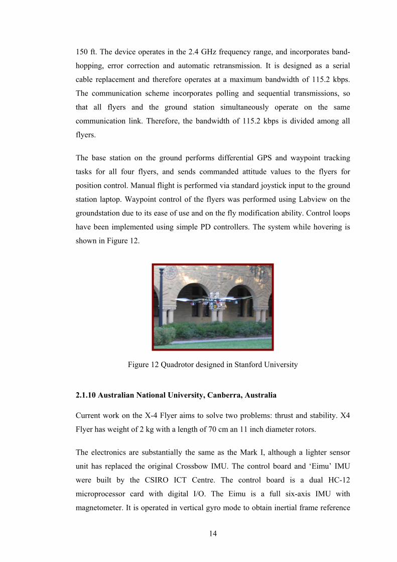
The base station on the ground performs differential GPS and waypoint tracking
tasks for all four flyers, and sends commanded attitude values to the flyers for
position control. Manual flight is performed via standard joystick input to the ground
station laptop. Waypoint control of the flyers was performed using Labview on the
groundstation due to its ease of use and on the fly modification ability. Control loops
have been implemented using simple PD controllers. The system while hovering is
shown in Figure 12.
Figure 12 Quadrotor designed in Stanford University
2.1.10 Australian National University, Canberra, Australia Current work on the X-4 Flyer aims to solve two problems: thrust and stability. X4
Flyer has weight of 2 kg with a length of 70 cm an 11 inch diameter rotors.
The electronics are substantially the same as the Mark I, although a lighter sensor
unit has replaced the original Crossbow IMU. The control board and ‘Eimu’ IMU
were built by the CSIRO ICT Centre. The control board is a dual HC-12
microprocessor card with digital I/O. The Eimu is a full six-axis IMU with
magnetometer. It is operated in vertical gyro mode to obtain inertial frame reference

15
angles. There is room inside the frame for mounting the Eimu as close to the centre
of gravity as possible.
Unlike the Mark I, the Mark II incorporates simple onboard proportional-integral-
derivative control. The previous iteration used a slow, off-board control system
connected to the flyer by a tether. It is anticipated that the convenient aerodynamics
of the X-4 had made sophisticated control unnecessary. In conjunction with onboard
power, this allowed the flyer to be entirely self-contained. MARK II shown in figure
13.
Figure 13 X-4 Flyer Mark II.
2.2 Applied Control Systems
For the control of UAVS there are several methodologies used in the literature.
Control systems that are used for the control of a helicopter type flying machine are:
robust feedback controllers based on H∞ techniques [4], fuzzy control, PD controllers
[3], back-stepping controllers [3], Neural-Network Adaptive Flight Control [3]. For
the experimentation done on the Stanford draganflyer UAVS, nonlinear control
methods are used that uses discrete-time dynamic inversion, under input saturation
[7]. Another study done at the University of Pennsylvania showed another control
example, which used a vision based control methodology for the control of UAVS
[6].
16
2.3 Employed Sensors
In order to establish a certain control mechanism for a system the changing states and
properties of its internal and external environment must be known to the system. In
other words the important parameters for the system control must be monitored and
fed back to the system.
In order to establish this requirement some sensors must be used that are specific for
different observation environments. For instance, for the control of the navigation of
a flying machine an Inertial Measurement Unit is needed. This unit is composed of
some several types of sensors such as accelerometers, gyros, etc. Gyro type sensors
are used in order to sense the rate of change of the rotation around a certain axis
where as accelerometer type sensors are used for the detection of the linear
acceleration of the system. There are several types of gyros and accelerometers on
the market. MEMS accelerometers for instance work on the principle of capacitive
changes where as piezo-accelerometers uses piezoelectricity principle. The same is
true for the gyros also. Fiber optic gyros are expensive and bulky whereas MEMS
gyros are cheap and light.
In order to detect the number of revolutions of a rotating shaft in the system, an
encoder or a magnetic rotation sensor can be used. This rotating shaft for example
can be the shaft of a propeller of a helicopter. Determination of the rotation speed of
this propeller shaft is a vital job for the control of the helicopter body.
For the determination of the position of the flying machine on 3D space a
differential GPS sensing is required. This system when used in cooperation with
inertial navigation system navigation becomes less erroneous and much more
reliable. In addition to those sensor sets some compass and Magnetometer type
sensors are also used in some systems to detect the earth’s magnetic field for the
calculation of the direction and altitude parameters. As a proximity sensor Sonar and
Radar Altimeters are used [7]. They give information about the proximity obstacle
and target positions. In order to monitor the system sources like batteries, and fuel
condition Vehicle Telemetry sensors are used [10]
17
CHAPTER 3
3. MATHEMATICAL MODEL OF THE HOVERING PLATFORM
3.1 Assumptions of the Model
The physical setup is a complex structure and without simplifying assumptions it is
cumbersome to derive the mathematical model of it. The following are some
assumptions that are used in developing the mathematical model of the quadrotor.
• The carbon fiber structure is supposed to be rigid.
• The helicopter has a perfectly symmetrical structure so; the matrix of inertia
will supposed to be diagonal.
• The bearing pressure and the trail of each engine are proportional to the
square speed, which is an approximation very close to the aerodynamic
behavior.
• hovering condition is assumed.
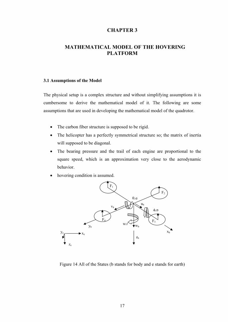
Figure 14 All of the States (b stands for body and e stands for earth)
ψ,r wb
θ,q
vb
ze
xe ye xb
zb
yb
ub
φ,p
F1
F4 F3
F2

18
3.2 Derivation of the State Equations
The quadrotor system is a six degrees of freedom system defined with twelve states.
Six out of twelve states govern the attitude of the system (Figure 14). These include
the angles (φ, θ, ψ) and angular rates (p, q, r) around the three orthogonal body axes.
The other six states are the three positions and three linear velocities of the center of
mass of the quadrotor with respect to a fixed reference frame (earth fixed frame).
Note that there are two coordinate frames one of them is fixed at the ground and the
other is fixed at the center of gravity of the quadrotor. In order to derive the state
equations with respect to those frames the rotation matrices between two coordinate
frames must be derived.
For each axis transformation matrices can be written as,
⎥⎥⎥
⎦
⎤
⎢⎢⎢
⎣
⎡−=
φφφφ
cossin0sincos0001
xR (1)
⎥⎥⎥
⎦
⎤
⎢⎢⎢
⎣
⎡
−=
θθ
θθ
cos0sin010
sin0cos
yR (2)
⎥⎥⎥
⎦
⎤
⎢⎢⎢
⎣
⎡ −=
1000cossin0sincos
ψψψψ
zR (3)
Resultant transformation matrix
xyz RRRR ..= (4)
⎥⎥⎥
⎦
⎤
⎢⎢⎢
⎣
⎡
−−=
φθθφθφφ
φθφθθ
cos.coscos.sinsinsincos0
cos.sinsin.sincos. xy RR (5)
⎥⎥⎥
⎦
⎤
⎢⎢⎢
⎣
⎡
−−
⎥⎥⎥
⎦
⎤
⎢⎢⎢
⎣
⎡ −==
φθθφθφφ
φθφθθψψψψ
cos.coscos.sinsinsincos0
cos.sinsin.sincos.
1000cossin0sincos
.. xyz RRRR (6)

19
⎥⎥⎥
⎦
⎤
⎢⎢⎢
⎣
⎡
−−−+−
=φθθφθ
ψφφθψφψφθψθψφψφθψψφφθψθψ
cos.coscos.sinsincos.sincos.sin.sincos.cossin.sin.sincos.sinsin.sincos.sin.cossin.cossin.sin.coscos.cos
R (7)
Linear velocities along body axes can be transformed into inertial frame using the
transformation matrix R given above
[ ] [ ]TTEEE wvuRzyx
dtdx ==& (8)
⎥⎥⎥
⎦
⎤
⎢⎢⎢
⎣
⎡=
⎥⎥⎥
⎦
⎤
⎢⎢⎢
⎣
⎡
wvu
Rzyx
.&
&
&
(9)
cbax ++=& (10)
where,
wc
vb
ua
).sin.sincos.sin.(cos
).sin.cossin.sin.(cos
.cos.cos
φψφθψ
ψφφθψ
θψ
+=
−=
=
fedy ++=& (11)
where,
wfve
ud
)cos.sincos.sin.(sin).cos.cossin.sin.(sin
.cos.sin
ψφφθψφψφθψ
θψ
−=−=
=
wvuz .cos.cos.cos.sin.sin φθθφθ ++−=& (12)
Angular rates along body axes can be transformed into Euler rates using the
transformation matrix T given below
[ ] [ ]TT rqpTdtd
=ψθφ (13)

20
⎥⎥⎥
⎦
⎤
⎢⎢⎢
⎣
⎡−=
φθφθφφ
φθφθ
cos.secsin.sec0sincos0
cos.tansin.tan1T (14)
⎥⎥⎥
⎦
⎤
⎢⎢⎢
⎣
⎡=
⎥⎥⎥
⎦
⎤
⎢⎢⎢
⎣
⎡
rqp
T .ψθφ
&
&
&
(15)
φθφθφ cos.tan.sin.tan. rqp ++=& (16)
φφθ sin.cos. rq −=& (17)
φθφθψ cos.sec.sin.sec. rq +=& (18)
For the system at hand the “Newton’s Second Law of Motion” can be written as
F=ma (19)
where m is the mass of the system, a is the acceleration and F is the net force acting
on the body, then,
( ) [ ] [ ]TTT
wvurqpwvuVdtd
mGF ×+⎥⎦
⎤⎢⎣⎡==+
...1 (20)
Here G is denoting the gravitational force acting on the body. If the body
acceleration term is taken out,
[ ] [ ] [ ] [ ] [ ]TTTTTzyx
T wvurqpgRFFFm
wvu ×−+= 001&&& (21)
The cross product term can be opened as,
[ ] [ ]⎥⎥⎥
⎦
⎤
⎢⎢⎢
⎣
⎡
−−−
=×uqvpwpurvrwq
wvurqp TT
......
(22)
And also the gravitational acceleration vector can be rotated as,
[ ]⎥⎥⎥
⎦
⎤
⎢⎢⎢
⎣
⎡−+
=g
gggg
gR TT
.cos.cos.cos.sin.cos.sin.sin.sin.sin.cos.sin.cos
00φθ
ψφφθψφψφθψ
(23)

21
Then the rate of the body linear velocities can be calculated as,
⎥⎥⎥
⎦
⎤
⎢⎢⎢
⎣
⎡
−−−
−⎥⎥⎥
⎦
⎤
⎢⎢⎢
⎣
⎡−+
+⎥⎥⎥
⎦
⎤
⎢⎢⎢
⎣
⎡=
⎥⎥⎥
⎦
⎤
⎢⎢⎢
⎣
⎡
uqvpwpurvrwq
ggggg
FFF
mwvu
z
y
x
......
.cos.cos.cos.sin.cos.sin.sin.sin.sin.cos.sin.cos
1
φθψφφθψφψφθψ
&
&
&
(24)
vrwqggFm
u x ..sin.sin.cos.sin.cos..1+−++= φψφθψ& (25)
wpurggFm
v y ..cos.sin.cos.sin.sin..1+−−+= ψφφθψ& (26)
uqvpgFm
w z ..cos.cos..1+−+= φθ& (27)
By equating the change of angular momentum to the net moment on the system,
[ ] [ ] [ ] [ ]TTTT rqpIrqprqpIrqpIdtd
dtdH ... ×+== &&& (28)
[ ] [ ] [ ] [ ]TTTTzyx rqpIrqprqpIMMM .. ×+= &&& (29)
[ ] [ ] [ ] [ ]TTTzyx
T rqpIrqpIMMMIrqp ... 11 ×−= −−&&& (30)
So 12 state equations can be written as,
cbax ++=& (31)
where,
wcvb
ua
).sin.sincos.sin.(cos).sin.cossin.sin.(cos
.cos.cos
φψφθψψφφθψ
θψ
+=−=
=
fedy ++=& (32)
where,
22
wf
ve
ud
)cos.sincos.sin.(sin
).cos.cossin.sin.(sin
.cos.sin
ψφφθψ
φψφθψ
θψ
−=
−=
=
wvuz .cos.cos.cos.sin.sin φθθφθ ++−=& (33)
φθφθφ cos.tan.sin.tan. rqp ++=& (34)
φφθ sin.cos. rq −=& (35)
φθφθψ cos.sec.sin.sec. rq +=& (36)
vrwqggFm
u x ..sin.sin.cos.sin.cos..1+−++= φψφθψ& (37)
wpurggFm
v y ..cos.sin.cos.sin.sin..1+−−+= ψφφθψ& (38)
uqvpgFm
w z ..cos.cos..1+−+= φθ& (39)
[ ] [ ] [ ] [ ]TTTzyx
T rqpIrqpIMMMIrqp ... 11 ×−= −−&&& (40)
State Vector defining the attitude dynamics is given below
[ ]Trqpx ψθφ= (41)
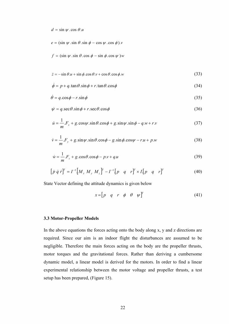
3.3 Motor-Propeller Models In the above equations the forces acting onto the body along x, y and z directions are
required. Since our aim is an indoor flight the disturbances are assumed to be
negligible. Therefore the main forces acting on the body are the propeller thrusts,
motor torques and the gravitational forces. Rather than deriving a cumbersome
dynamic model, a linear model is derived for the motors. In order to find a linear
experimental relationship between the motor voltage and propeller thrusts, a test
setup has been prepared, (Figure 15).

23
Figure 15 Motor test setup for thrust calculation.
In this setup the motor is constrained in a thick metal to keep it in a certain
orientation. And this module is placed on the digital 1% precise scale. Then the
motor voltage and current measured at 0.1 V increments. The results of this
experiment are shown in the graphs below (Figure 16, Figure 17, Figure 18, Figure
19).
T = 22,4935Vm - 9,732
-20
0
20
40
60
80
100
120
140
160
1,2 1,4 1,6 1,8 2 2,2 2,4 2,6 2,8 3 3,2 3,4 3,6 3,8 4 4,2 4,4 4,6 4,8 5 5,2 5,4 5,6 5,8 6
Motor voltage (V)
1st M
otor
thru
st (g
)
Figure 16 Test results of the 1st Motor (voltage vs. thrust(T))

24
T = 22,4926Vm - 9,5271
-20
0
20
40
60
80
100
120
140
160
1,2 1,4 1,6 1,8 2 2,2 2,4 2,6 2,8 3 3,2 3,4 3,6 3,8 4 4,2 4,4 4,6 4,8 5 5,2 5,4 5,6 5,8 6
Motor voltage (V)
2nd
Mot
or th
rust
(g)
Figure 17 Test results of the 2nd motor (voltage vs. thrust(T))
T= 22,6127Vm - 9,8941
-20
0
20
40
60
80
100
120
140
160
1,2 1,4 1,6 1,8 2 2,2 2,4 2,6 2,8 3 3,2 3,4 3,6 3,8 4 4,2 4,4 4,6 4,8 5 5,2 5,4 5,6 5,8 6
Motor voltage (V)
3rd
Mot
or th
rust
(g)
Figure 18 Test results of the 3rd motor (voltage vs. thrust(T))
T = 22,6184Vm - 9,5805
-20
0
20
40
60
80
100
120
140
160
1,2 1,4 1,6 1,8 2 2,2 2,4 2,6 2,8 3 3,2 3,4 3,6 3,8 4 4,2 4,4 4,6 4,8 5 5,2 5,4 5,6 5,8 6
Motor voltage (V)
4th
Mot
or th
rust
(g)
Figure 19 Test results of the 4th motor (voltage vs. thrust(T))
It is seen in the experiments that this relationship between the motor thrust and its
voltage is a nonlinear one. In order to use LQR, this motor relation must be
linearized. For this purpose a best fitting line to the nonlinear curve is derived using
least squares method and it is this line that is used in the model.

25
For each motor the line representing their behavior is derived, which are given as;
F1=9.81*(22.4935*Vm1-9.732)/1000 (42)
F2=9.81*(22.4926* Vm2-9.5271)/1000 (43)
F3=9.81*(22.6127* Vm3-9.8941)/1000 (44)
F4=9.81*(22.6184* Vm4-9.5805)/1000 (45)
Here F’s are the motor thrust values in Newtons. And Vm’s, which are the inputs of
the system, are the motor voltages in volts. Therefore, total thrust of the motors can
be calculated as;
Fz=-(F1+F2+F3+F4) (46)
And the moment forces can be approximated as;
Mx=L*(F2-F4) (47)
My=L*(F1-F3) (48)
Mz=-c*F1+c*F2-c*F3+c*F4 (49)
Here L is equal to the distance from the free end of the frame bars to the center of
gravity of the quadrotor which is equal to 0.21 m for the quadrotor system at hand.
And c is a constant relating the trust forces to the moment around the vertical body
axis, the value of which is taken as 0.1 from a similar study done in literature [32].
The disturbances along x and y body axis are assumed to be negligible in an indoor
flight condition so the forces acting along those axes are taken to be zero i.e.
Fx=0 (50)
Fy=0 (51)
In derivation of the mathematical model the inertial parameters of the system are
needed. The masses of different parts of the system are given below as well as the
inertias about the three orthogonal axes. Moment of inertias are taken from a similar
study done in literature [6] so they are approximations rather than being exact.

26
Table 1 Inertial Parameters
PARTS MASS (Grams)
1 BLADE 9 1 MOTOR 51 CARBON STICKS 3.46 FULL DRAGANFLYER 467.21 1 MOTOR HOLDER 2.82 BATTERY 91.13 HARDWARE 48.80 PLASTIC CAP 9.00 FINAL TOTAL MASS 320
AXIS INERTIAS (kg.m2) Ix (body) 0.0142 Iy (body) 0.0142 Iz (body) 0.0071

27
3.4 Linearization of the Nonlinear State Equations The governing state equations are non-linear. These equations have to be linearized
about the stable hovering conditions. Linearizations of the nonlinear state equations
are done by using jacobians of the nonlinear state equations with respect to the states
and the inputs around hovering conditions [ ]1.0000000 =x .
Given a set of state equations ( )xfy = in n equations in n state variables nxx ,..,1 ,
the Jacobian matrix of a set of state equations can be calculated as shown in equation
52.
⎥⎥⎥⎥⎥⎥⎥
⎦
⎤
⎢⎢⎢⎢⎢⎢⎢
⎣
⎡
∂∂
∂∂
∂∂
∂∂
=∂∂
OMM
K
K
2
2
1
2
2
1
1
1
xf
xf
xf
xf
xf (52)
The Jacobian matrix of the non-linear state equations with respect to the states at the
given initial conditions is given in the equation 53.
0000995.00998.000000998.0995.00000001000000000000000000
xx
xfA
=⎥⎥⎥⎥⎥⎥⎥⎥
⎦
⎤
⎢⎢⎢⎢⎢⎢⎢⎢
⎣
⎡
−
=∂∂
= (53)
The input matrix, B , of the state-space representation is formed by taking the
jacobian of the state equations with respect to the input vector, u (equation 54). The
inputs of the system are the motor voltages which are denoted with letters u1,..,u4.

28
( )⎥⎥⎥⎥
⎦
⎤
⎢⎢⎢⎢
⎣
⎡
=
4
3
2
1
uuuu
tu (54)
The matrix B for the states at hovering condition is shown in equation 55.
00000000000006049.186049.186049.186049.1801622.1401622.141622.1401622.140
xx
ufB
=⎥⎥⎥⎥⎥⎥⎥⎥
⎦
⎤
⎢⎢⎢⎢⎢⎢⎢⎢
⎣
⎡
−−−
−
=∂∂
= (55)
Three gyroscopes measure the set of angular velocity components{ }rqp ,, , one two
axis accelerometer is assumed to measure pitch (φ) and roll (θ) angles, and one
magnetometer measures the yaw angle (ψ), which are all state variables. The direct
transition matrix D is taken to be zero because there is no direct coupling between
input and output of the system. On the other hand, the output matrix C given in
equation (56) consists of the measurement of three six state variables by the sensors.
⎥⎥⎥⎥⎥⎥⎥⎥
⎦
⎤
⎢⎢⎢⎢⎢⎢⎢⎢
⎣
⎡
=
100000010000001000000100000010000001
C (56)
The output of the system turns out to be as;

29
⎥⎥⎥⎥⎥⎥⎥⎥
⎦
⎤
⎢⎢⎢⎢⎢⎢⎢⎢
⎣
⎡
=+=
ψθφrqp
DuCxy (57)
Where, p – the pitch angular rate, q – the roll angular rate, r – the yaw angular rate, φ − the pitch angle, θ − the roll angle, ψ − the yaw angle,

30
CHAPTER 4
4. LQR DESIGN FOR ATTITUDE STABILIZATION
In this study, the attitude stabilization is aimed. For this purpose the chosen
controller is LQR. In order to use LQR the nonlinear system at hand must be
linearized around a certain operating point. For this purpose, the jacobians of the
nonlinear state equations are derived with respect to the states and the inputs. In this
way the state space matrices A, B, C, and D are obtained after substituting the
operating point state values. The controllability of the physical system is examined
by checking the controllability matrix and it is found to be fully controllable for all
12 states (see Appendix 1). Attitude dynamics of the system is completely observable
with the utilized sensor set. Observability analysis is also carried out by checking the
rank of observability matrix (see Appendix 1). Therefore those states governing the
attitude of the system could be controlled with the chosen sensor set.
4.1 Linear Quadratic Regulator
Linear quadratic regulator is a widely used modern control technique. It is preferred
because of its easy implementation and its optimality for linear time invariant
systems. It is an optimal and robust technique for Multi Input Multi Output (MIMO)
control. Using this method the optimal control feedback coefficients are derived, the
derivation of which is given in the following lines.
Given a linear time invariant system in state variable form as [15];
BuAxx +=&
DuCxy += (58)
( ) 00 xx =
where x is the states of the system, u is the input, A is the system matrix, B is the
input matrix, C is the output matrix and the D is the direct transition matrix. LQR
controller tries to minimize the performance index given as;

31
( ) ∫∞
=0
)()( dttytyuJ T
( ) ( ) ( ) ( ) ( ) ( ) ( )( )∫∞
++=0
2 dttDuCtxtDuDtutCxCtxuJ TTTTTT (59)
Where the above given equation terms can be replaced with their equivalents as;
RDDSDCQCC
T
T
T
=⋅
=⋅
=⋅
(60)
( ) ( ) ( ) ( ) ( ) ( ) ( )( )∫∞
++=0
2 dttSutxtRututQxtxuJ TTT (61)
The linear solution that minimizes this index is given by some linear function of
states;
Kxu −= (62)
and the feedback gain is given as;
( )TT SPBRK +−= −1 (63)
After the required substitutions are done, the feedback gain matrix for the system is;
⎥⎥⎥⎥
⎦
⎤
⎢⎢⎢⎢
⎣
⎡
−−−−−−
−−
=
236.208114.152495.200097.6236.20711.702495.29581.50
236.208114.152495.200097.62361.20711.702495.29581.50
K (64)
Linear quadratic regulator solves also a Ricatti equation given as;
( ) ( ) 01 =+++−+ − QSPBRSPBPAPA TTT (65)
where P is the stabilizing solution to the Ricatti equation [15].
( ) ( ) 000
PxxdttytyJ TT == ∫∞
(66)

32
In the above equation (66), Q is the state control matrix and it is important when
defining which states are more important and which are less important. It means that,
larger values of Q generally results in the poles of the closed loop system being left
in the s-plane so that the states decay faster to zero. On the other hand, R is the
performance index matrix also referred as the cost of inputs. Experiments are done
with different Q and R matrices to get the best response [15].
In Figure 21 the change in six states can be seen during LQ regulation for both the
nonlinear and the linear state space model (Figure 20). All states are regulated to
zero in both systems.
Figure 20 The LQR system for nonlinear and linear state-space models

33
0 0.2 0.4 0.6 0.8 1 1.2 1.4-10
-8
-6
-4
-2
0
2x 10⁻⁵ Pitch Angular Rate
Time (sec)P
itch
Ang
ular
Rat
e (ra
d/se
c)0 0.2 0.4 0.6 0.8 1 1.2 1.4
-8
-6
-4
-2
0
2x 10⁻³ Roll Angular Rate
Time (sec)
Rol
l Ang
ular
Rat
e (ra
d/se
c)
0 0.2 0.4 0.6 0.8 1 1.2 1.4-0.1
-0.08
-0.06
-0.04
-0.02
0Yaw Angular Rate
Time (sec)
Yaw
Ang
ular
Rat
e (ra
d/se
c)
0 0.2 0.4 0.6 0.8 1 1.2 1.4-1
0
1
2
3
4x 10⁻⁵ Pitch Angle
Time (sec)
Pitc
h A
ngle
(rad
)0 0.2 0.4 0.6 0.8 1 1.2 1.4
-3
-2
-1
0
1
2x 10⁻³ Roll Angle
Time (sec)
Rol
l Ang
le (r
ad)
0 0.2 0.4 0.6 0.8 1 1.2 1.40
0.02
0.04
0.06
0.08
0.1Yaw Angle
Time (sec)Y
aw A
ngle
(rad
)
Figure 21 Comparison of the nonlinear and state space models for a 0.1 rad disturbance in yaw angle (continuous line represents the State space model and
dashed line represents nonlinear model)

34
CHAPTER 5
5. STRUCTURE AND TEST BENCH
This chapter discusses the hardware used in the development of the quadrotor. The
commercially available hardware components have been used in this research. Steps
of the physical integration of the system have been discussed in this chapter.
5.1 The Frame of the Quadrotor
For the body of the quadrotor the frame of the commercial quadrotor named
DraganFlyer Vti model is used. The frame composed of carbon tubes attached with a
plastic hub from their ends forming a plus shape. At the other ends of the carbon
tubes motor-propeller assemblies are attached. The 15 cm carbon tubes are used
because of their light weight (4 g) and high stiffness properties. Total frame
assembly weighs about 270 g without any electronic hardware. Instead of the original
electronic circuits a custom board has been designed and attached on board later.
5.2 Sensors Used in the System The sensor alternatives (Figure 22) (Table 2) that can be used in this study are
Murata ENC03 gyros, Silicon Sensing CRS02 or CRS04 gyros, Honeywell
magnetometer and Parallax compass module, Memsic accelerometers and Analog
devices accelerometers, which are also available in our Robotics laboratory.

35
Figure 22 (a) Accelerometer (Analog devices) (b) Magnetometer (Honeywell) (c)
Accelerometer (Memsic) (d) Gyroscope (Murata) (e) Compass Module (Parallax) (f)
Gyroscope (Silicon sensing) (g) Gyroscope (Silicon Sensing)
Table 2 Available Sensors
Analog devices ADXL203EB Dual Axis Accelerometer
Analog devices ADXL202 Dual Axis Accelerometer
Analog devices ADXL311 Dual Axis Accelerometer
Analog devices ADXRS300ABG 300deg/s single chip rate gyro
Analog devices ADXRS150ABG 150 deg./sec. angular rate sensor
Honeywell hmc 1023 3-axis magnetometer
Honeywell Hmc 2003 3-axis magnetometer
Honeywell Hmr 2300R-485 3-axis magnetometer
Honeywell Hmr 3000-demo-232 Compass module

36
Honeywell Hmr 3200-demo-233 Compass module
Honeywell Hmr 3300-demo-234 Compass module
Parallax hitachi HM55B Compass module
Murata
ENC 03 Angular rate gyro
Silicon sensing CRS04c Single axis angular rate sensor
Silicon sensing CRS02c Single axis angular rate sensor
memsic MX2125 low cost, dual-axis thermal accelerometer
Most of the sensors at hand provides digital outputs, which requires additional
hardware to transmit data to the PC terminal. In addition to that some digital output
sensors have low resolution results. For example, parallax HM55B compass module
has 11 bit resolution with a 20 ms conversion time. Because of these deficiencies
instead of digital output sensors, analog output sensors are chosen. ADXRS150 EB
Gyro evaluation board, ADXL203 accelerometer module and HMC2003 3 axis
magnetometer modules are used. Their properties are further discussed in the below
topics.
5.2.1 Accelerometer
Analog devices ADXL203 accelerometer (Figure 23) was used to measure the roll
and pitch angles of the system. In order to do these measurements it was worked in
tilt measuring mode.

37
Figure 23 Accelerometer (ruler is in centimeters)
The accelerometer evaluation board (Figure 24) is factory-set for a bandwidth of
50Hz which is higher than the required filter frequency. In order to obtain a proper
bandwidth, the outputs of the sensor are filtered using 1 μF capacitors. These
capacitors work as low pass filter with cutoff frequency of 5 Hz [42].
Figure 24 ADXL203EB accelerometer evaluation board
The accelerometer measures the tilt angles, which are assumed to represent the Euler
angles. Therefore, unlike the gyroscopes, that measure only the angular rates, the tilt
sensor placed as close as possible to the center of gravity. The mounting was done on
to the lower PCB’s center as shown in the Figure 24 using 2 mm screws.

38
5.2.2 Gyroscopes
Three Analog devices MEMS Gyroscopes (model ADXRS150) were used in the
system. These gyros are soldered on an evaluation board, like the one shown in
Figure 25. These evaluation boards weigh three grams each, and are about 2,54 cm
long by 1.27 cm wide and costs $50. The chip on this board is also available from
Analog Devices Inc. However; the evaluation board does not require any external
resistors or capacitors for the gyroscope to be used. Also, the gyroscope’s ball grid
array chip connections, which are difficult to solder by hand, have already been
soldered onto the evaluation board.
The sensor uses a resonator gyro that senses Coriolis motion and is capable of
measuring +/−150 degrees per second of angular velocity. The chip produces an
analog voltage output (between 0.25 and 4.75 V for a 5 volt source) that is
proportional to the angular velocity about the axis normal to the top surface of the
gyroscope package. The voltage increases for clockwise rotation (while looking
down at the top of the chip) of the gyroscope. The noise density of the gyroscope,
which is defined as the average noise at any frequency (f, in Hz) in the bandwidth of
the part, is 0.05 o/sec/pF. The initial null point is 2.5 V, but this can change by a
maximum of 300 mV for a temperature range of −40 to 85oC. The sensitivity of the
gyroscope varies from 11.25 to 13.75 mV per degree per second over the
gyroscope’s operating temperature range. The gyroscope includes signal
conditioning electronics to help preserve the signal in noisy environments. The
bandwidth of the surface mount gyro chip can be set using external resistors and
capacitors.

39
Figure 25 A picture of the gyroscope evaluation board ADXRS150EB (ruler is in centimeters).
The bandwidths of the gyros are factory-set at 40 Hz (Figure 25). Each one of the
gyros was placed on different PCBs which are perpendicular to each other like the
one shown in the Figure 26. The axis of measurement of the gyro is pointing out of
the paper in Figure 25. Therefore in order to measure angular rates around three
orthogonal body axes the gyros were placed such that their axis of measurement
stayed parallel to the corresponding axes of rotation (Figure 26).
5.2.3 Magnetometer Honeywell HMC2003 model 3 axis magnetometer was installed on to the PCB. It is
shown in the Figure 26 with an arrow. Magnetometer gives analog voltage outputs
proportional to the magnetic field along each orthogonal body axis. In this
configuration the magnetometer is used only to measure the yaw angle around the
earth-fixed vertical axis. Since the system’s attitude is stabilized near hovering, only
one axis measurement of magnetometer is utilized, which is the horizontal axis.

40
Figure 26 Magnetometer at the lower left corner and three gyros at the back of it (magnetometer shown with an arrow)
On the sensor board there are three orthogonal MEMs gyroscopes (ADXRS150-
Analog devices), one Magnetometer (HMC2003-Honeywell) and a voltage regulator
ic (7805). The circuit diagram for the sensor set is given in Figure 27.
Figure 27 Circuit diagram of the gyro hardware
+5 V 7805+12 V
0 V
ADXRS150 EB
ADXRS150 EB
ADXRS150 EB
RATE OUT
RATE OUT
RATE OUT
0 V
+5 V
0 V 0 V
+5 V
+5 V
X RATE OUT
HMC2003 Magnetometer +12 V
0 V
Y out
X out
+5 V
0 V
ADXL203 EB
0 V
100μF

41
Figure 28 IRFZ44N n-channel Mosfet transistor schematic for motor drivers
There is another circuit board beneath the gyro board that is carrying four n-channel
mosfet transistors. These transistors are the motor driving transistors. The schematic
for a single n-channel Mosfet motor driver is shown in Figure 28.
5.3 Drivers In Draganflyer Vti model four mosfet transistors model iflz44n are used and are
driven in switching mode with a 5 V PWM signal which has a frequency of 178 Hz
[23] (Figure 29).
Figure 29 Mosfet IRLZ44N driven in switching mode [34]
Irfz44n
G D S
M
0 V +12 V
Optocouplers PWM signal
Motor

42
Mosfet’s input impedances are very high whereas their on resistances are very low
(around 0.022 Ω). These properties are desired on motor driver applications where
high currents are needed. In high current conditions the energy dissipation on the
transistor increases with the increase in their on resistances. So the more the
resistances are the more it dissipates heat, which may cause changes in the behavior
of the transistor [33].
PWM driving technique is more efficient and easily produced with logic circuitry
such as microcontrollers, which makes it the proper choice for driving the motors at
hand. [35]
Logic level gate drive mosfets are suitable for directly connecting them to
microcontrollers and other logic ic’s. This property prevents the usage of other gate
driving integrated circuits. For instance, draganflyer Vti model uses IRLZ44 logic
level gate drive mosfets.
There are some readily available motor drivers. Such as simple H bridge motor
driver [37].Unfortunately this driver doesn’t include isolation for noise. And the
motor voltage is in the range +6 V and +36.0 V range, which is outside the voltage
range of our motors. Alternatively there are other readily available speed controllers
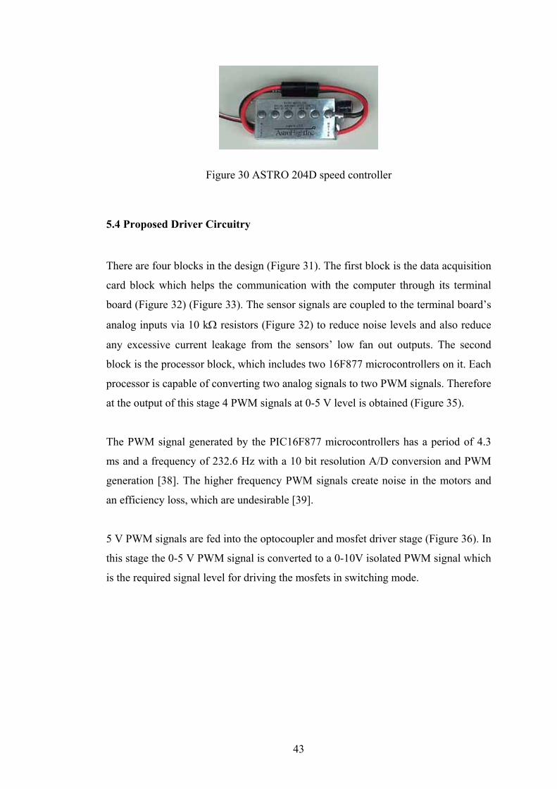
such as Astro flight 204D speed controller [36] [35]. This controller (Figure 30) is
designed for large Cobalt Motors. It is rated at 60 amps at 60 V, so it can handle
large motors like the Cobalt 90 motor. It can also be used with other cobalt or ferrite
brushed motors.
The 204D has optocoupler on the input to reduce chance of radio interference from
conducted motor noise. There is a built in voltage doubler for solid MOSFET drive
and the control is all digital using a special micro processor.
The four 80N06 mosfets used in the motor drive circuit have a combined resistance
of less than 2 milliohms. This low resistance lets the control run cool and gives the
204D control a continuous current rating of 50 A.
43
Figure 30 ASTRO 204D speed controller
5.4 Proposed Driver Circuitry There are four blocks in the design (Figure 31). The first block is the data acquisition
card block which helps the communication with the computer through its terminal
board (Figure 32) (Figure 33). The sensor signals are coupled to the terminal board’s
analog inputs via 10 kΩ resistors (Figure 32) to reduce noise levels and also reduce
any excessive current leakage from the sensors’ low fan out outputs. The second
block is the processor block, which includes two 16F877 microcontrollers on it. Each
processor is capable of converting two analog signals to two PWM signals. Therefore
at the output of this stage 4 PWM signals at 0-5 V level is obtained (Figure 35).
The PWM signal generated by the PIC16F877 microcontrollers has a period of 4.3
ms and a frequency of 232.6 Hz with a 10 bit resolution A/D conversion and PWM
generation [38]. The higher frequency PWM signals create noise in the motors and
an efficiency loss, which are undesirable [39].
5 V PWM signals are fed into the optocoupler and mosfet driver stage (Figure 36). In
this stage the 0-5 V PWM signal is converted to a 0-10V isolated PWM signal which
is the required signal level for driving the mosfets in switching mode.

44
Figure 31 Driver system block diagram
Figure 32 Terminal board
humusoft mf 614 data acquisition card
TWO 16f877 processor
TLP250 Mosfet gate driving optocouplers
Four Mosfets IRLZ44
+10V PWM signal
+5V PWM signal
Analog Signals From humusoft mf 614

45
Figure 33 The Block diagram for the data acquisition card terminal board
Figure 34 A view of the hardware system
4 Analog outputs for the motor drivers
HUMUSOFT MF614 DATA ACQUISITION CARD TERMINAL BOARD
5 V output
Analog to 5 V PWM converter
PIC16F877 processor board
Sensor Circuit 3 Gyros
2 axis tilt sensor 1 axis magnetometer
6 Analog inputs for
the sensors
Power Cables
Data acquisition card terminal
Voltage to PWM converter
PIC16F877 processors and
Mosfet gate driving optocouplers
PC terminal (Simulink)

46
Figure 35 Voltage to 5 V PWM converter
Figure 36 Mosfet gate driving optocouplers (TLP250)
TLC250 optocouplers (Figure 36) provide both mosfet gate driving and isolation
from motor circuitry, which prevents noise entering into the data acquisition board
[35].
IRFZ 44N is the preferred mosfet transistor for driving the motors. It can be driven
with a 10 V PWM signal, which is suitable for the system at hand [34].
Connects to the PWM
outputs of the 16F877 processors
Connector to the gates
of the mosfets
Analog inputs from
the data acquisition
card
5 V PWM outputs

47
The wires and connections made to the system effects the model of the system so in
order to minimize these effects the motor drivers are placed on board so that the thick
power cables are confined into the hardware onboard. Therefore only the signal
cables are extended from the body of the quadrotor.
The power mosfets are attached to properly sized heat sinks (Figure 37) and placed
closer to the outside corners of the PCB in order to dissipate the heat away easily
with the help of the air flowing due to the rotation of the propellers. The
characteristics of the mosfets change with their temperature so keeping their
temperature constant is paramount while they are working.
Figure 37 Electronic Hardware
In the experiments motors created high back emf voltages which when driven with
transistors may damage the mosfet transistors. So in order to eliminate these high
reverse voltages a small 22nf capacitor is placed between two terminals of each
motor (Figure 38). So when a high reverse voltage is created it is shorted through this
bypass capacitor.
Heat sinks

48
Figure 38 By-pass capacitor for high reverse inductive voltages
5.5 Power Supplies
The Agilient 6653A power supply (Figure 39) is used in the setup as an energy
source for the motors. It can supply 15 amperes at most at 35 V which is sufficient
for the system at hand. The system needs 10 amperes at most at 12 V. The switching
power supplies created noise in the sensor outputs so, instead of using AC connected
switching power supplies 12 volt lead acid battery is used to supply for the sensor set
(Figure 40).
Figure 39 Agilient 15 A / 35 V Power supply

49
Figure 40 Power supply for the sensor set
A button is placed near the PC terminal. In case of an emergency situation it cuts the
power going to the system as it is pressed (Figure 41).
Figure 41 emergency button
5.6 Driver Test Results Mabuchi DC motors of the system are tested after they are connected to the mosfet
driver stage. PWM test result can be seen in the Figure 42 for the proposed
controller.

50
Figure 42 PWM driven Mabuchi motor’s RMS voltage
The behavior of the driver is nonlinear (Figure 42). In order to use this data a
polynomial function is fitted to the test data. Then this polynomial function is used in
the Simulink model to obtain the proper motor voltages.

51
5.7 Test Bench
After all the parts are assembled together the final system looks like the one shown in
Figure 43.
Figure 43 Assembled Quadrotor
After the quadrotor assembly finished the options of experimental setup is
considered. One of them is hanging up the quadrotor body with a rope. This keeps
the system at a constant height. The two other translations and the three orientations
are free. However this setup has a disadvantage. When the system sways side ways
the connected rope creates a decoupling action which stabilizes the overall system to
certain extend [19] (Figure 44) (Figure 45).

52
(a) (b)
Figure 44 Cable connection
(a) (b)
Figure 45 Side sways
Another option of experimental setup is the one which has a spherical joint (Figure
46) [19]. It prevents the three translations but not three rotations.
Figure 46 The kneecap or spherical joint

53
The available spherical joints tested but their friction rates found to be effectively
high. Finally, rope assembly decided to be used in the test bench. But it was not
connected to the quadrotor frame with an offset like it was in Figure 44. Instead the
rope passed through an opening in the top PCB gyro board (Figure 48) and
connected to the center of the cross frame, which reduced the couples that had been
caused when an offset was given to the rope-frame connection.
Figure 47 Experimental setup
Figure 48 The hole at the centre of PCB
The final system is hanged with a rope from the center of gravity (Figure 47). And
each motor end is loosely supported with ropes in order to prevent large,
uncontrolled sways and establish safety during working.
The bundle of signal cables that are extended from the quadrotor are winded together
and extended close to the axis of center of gravity in order to reduce the torques
created by the wires.

54
CHAPTER 6
6. REAL TIME CONTROL IMPLEMENTATION
The control software is implemented in Matlab/Simulink. The Real Time Windows
Target and Real Time Workshop of the Matlab are utilized while controlling the
hardware in the loop system. The data acquisition card that is used for this purpose
was Humusoft MF614.
Humusoft MF614 data acquisition card has four analog output channels and eight
analog input channels. Drivers for Real-Time Windows Target, xPC Extended Real
Time Toolbox for MATLAB and drivers for windows are included. It also has four
quadrature encoder inputs (differential). Additionally, it has eight digital inputs and
outputs.
6.1 The Control Software
The control algorithm consists of several different stages. First stage is the data
acquisition stage. In this stage the information about the orientation of the quadrotor
are acquired from the sensors. In the second stage the orientation information is
multiplied with the LQR gain matrix. In the third stage the motor signals coming
from the LQR controller are sent to the motor drivers.
In the data acquisition stage the raw data (in volts) from the sensors are acquired via
the data acquisition card. In Simulink this job is done with an Analog input block
present under the Real-Time Windows Target library. The raw data obtained by the
Analog input blocks are the sensors’ outputs in V where as the data required by the
LQR controller must be in radians for the angles and radians per second for the
angular rates. In order to convert these raw voltage signals into proper units
conversion blocks are placed at the outputs of the Analog input Blocks. In Figure 50
the conversion block is shown on the right. In addition to the conversion block an
offset calibration block is also placed at Analog input block output in order to use for

55
later calibrations. Calibration block consists of a constant subtracted from the sensor
output signal (Figure 50).
In the second stage the orientation information obtained in the first stage is
multiplied with the LQR gain matrix K. The derivation of K matrix was given in
Chapter 4.
In the third stage the LQR control signals are output to the external motor driver
circuitry via the data acquisition card. In Simulink this job is done with an Analog
output block present under the Real-Time Windows Target library. The control
signal passes through some other Simulink blocks before it is outputted via the final
Analog output block. In Figure 49 LQR Motor signal block can be seen on the left.
This block links the LQR controller to the converter1 block which adjusts the signal
such that the voltage value ordered by the controller is seen on the motors. Then the
output of this converter block is added with an adjustable motor voltage reference for
thrust adjustment i.e. if the thrust of all four motors wanted to be increased the slider
gain block in Figure 49 can be used to increase the voltages on the motors. After the
summation operation the motor signal passes through a saturation block which
avoids voltages higher than 5 V and lower than 0 V to be given to the driver
circuitry. And finally the motor signals are outputted to the external driver circuitry
via the Analog Output Block as shown in Figure 49.
Figure 49 Simulink blocks for one motor
6.2 Calibration of Sensors In order to get the accurate orientation information the sensors they must be
calibrated well before the system is worked. The first thing to calibrate is the voltage
outputs of the sensors. For instance although the same model gyros are used in the

56
sensor set, their outputs are quite different from each other when they are tested in
still position.
So the first thing that should be done is to offset their output values such that they all
give zero output at still position. This is done using the calibration constant
mentioned in Figure 50.
In order to determine these offset values system is prepared for a calibration. System
kept still initially and leveled horizontally. The still position is important because the
voltage outputs of the gyros at 0 angular rates were required. During hovering these
voltage values are necessary to keep the attitude stable. For instance if a wrong
voltage value were assigned for zero angular rate value it would mean that the
sensor will see the system as not moving but the real system would be rotating with
the angular speed corresponding to the voltage output of the gyro.
After the system had been made still the output of the gyros were read for 100
seconds and then the mean of this signal were taken to find the approximate voltage
level corresponding to the zero angular rates. In Simulink this constant voltage value
is subtracted from the signal to offset the signal output to zero value as mentioned
before (Figure 50). The same steps are also repeated for the other sensors (Figure 51,
Figure 52).
Figure 50 A Sample Gyro Block

57
Figure 51 A sample accelerometer block
Figure 52 A sample magnetometer block
Table 3 Calibration constants (at room temperature ~200)
Sensor Name Calibration constant
Gyro (p) 1.4186
Gyro (q) 1.4081
Gyro (r) 1.4201
accelerometer (φ) 1.0002
accelerometer (θ) 0.8600
Magnetometer (ψ) 1.6700
After the calibration of the sensors (Table 3) for level and no-motion case their
maximum voltages at the limits are tested. For instance, the gyro Sensors that are
used in the system give their maximum and minimum voltages at angular rates above
150 0/sec so, using these principles the gyros are given maximum angular rates

58
turning by hand. And using these tests the sensor output voltages at maximum
angular rates are determined. The same thing is done for the tilt sensing
accelerometers. The accelerometers give maximum and minimum voltage outputs at
+/- 900 rotations. So, in order to determine those maximum and minimum voltage
levels the system is turned by hand to +/- 900 angles both in pitch and roll angles. For
the magnetometer the quadrotor is rotated around the vertical axis until the maximum
and minimum outputs are distinguishable at the sensor output readings.
When converting the sensor outputs to the corresponding units it is assumed that the
sensor outputs change linearly. So the equation representing this linearity had been
found using the two critical points. For instance for a gyro first point is zero motion
case at this point the angular rate is 0 rad/sec and the offset-voltage is zero. The
second critical point is the maxima point. At this point the output voltage is some
value and the angular rate is 2.618 rad/sec (150 0/sec) then a line fitting those two
points is assumed to be the output equation of the gyros. On the other hand, the tilt
sensing accelerometers measure the angles between -900 and +900. At level position
tilt sensors should give zero output so that their maximum output corresponds to
+900 of rotation and minimum output corresponds to -900 of rotation or vice versa
(depending on the sign convention). So, a line can be fitted to those critical points to
represent the output equation of the tilt sensors. The procedure for the magnetometer
is the same as the tilt sensors’ procedure. The only difference is that the rotation
angle is around the vertical axis.

59
Figure 53 The Control Blocks in Simulink
Shortly, the signal information obtained from the sensors are acquired by the data
acquisition card and then this information after processed fed to a LQR gain block,
which outputs to the driver the controlling signals in volts. Figure 53 summarizes
these software-implemented steps in Simulink. The signals sent to the driver are then
converted to PWM signals by using some external hardware and given to the motor
drivers. After this point on, these signals are able to conduct the control effort to the
motors. The whole system is summarized in the block diagram given below (Figure
54).

60
Figure 54 Hardware in the Loop System
1. Sensor outputs are read using
Analog input boxes
of Real Time
Windows Target
2. Sensor outputs are calibrated
for stationary and level position
3. Sensor outputs are low pass
filtered with an 8th order Butterworth
filter
4. Sensor outputs in volts are
converted to appropriate
units
6. The output of the
Multiplication block are
summed with a constant of
motor voltages
7. The motor signals are outputted
using Analog output boxes of Real Time
Windows Target
Software Simulink Real Time Windows Target 1khz Sample Time
Data Acquisition Card and its
Terminal
Hardware
Motor Drivers
Motors Sensors
5. Converted values are multiplied with the
LQR gain Matrix K
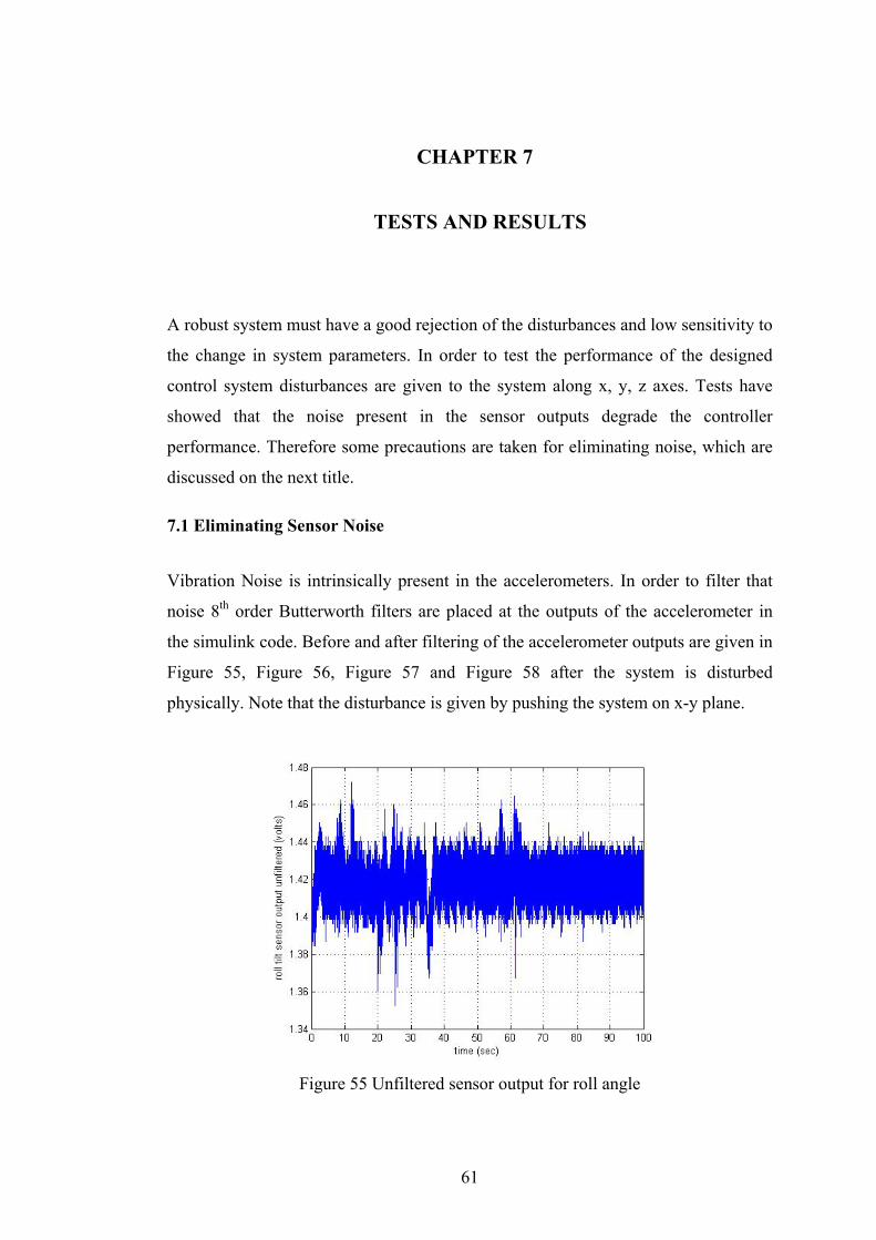
61
CHAPTER 7
7. TESTS AND RESULTS A robust system must have a good rejection of the disturbances and low sensitivity to
the change in system parameters. In order to test the performance of the designed
control system disturbances are given to the system along x, y, z axes. Tests have
showed that the noise present in the sensor outputs degrade the controller
performance. Therefore some precautions are taken for eliminating noise, which are
discussed on the next title.
7.1 Eliminating Sensor Noise
Vibration Noise is intrinsically present in the accelerometers. In order to filter that
noise 8th order Butterworth filters are placed at the outputs of the accelerometer in
the simulink code. Before and after filtering of the accelerometer outputs are given in
Figure 55, Figure 56, Figure 57 and Figure 58 after the system is disturbed
physically. Note that the disturbance is given by pushing the system on x-y plane.
Figure 55 Unfiltered sensor output for roll angle

62
In Figure 55 it is clearly seen that the signal is almost disappeared under the noise.
After the signal filtered with an 8th order Butterworth lowpass filter the signal
becomes distinguishable and the pattern of motion can be seen (Figure 56).
Figure 56 Filtered Roll angle measurement with a 8th order Butterworth lowpass filter with 10 Hz bandwidth
Figure 57 Unfiltered sensor output for pitch angle
Time (sec)
Roll angle (Radian)

63
Figure 58 Filtered pitch angle with a 8th order Butterworth lowpass filter with 10 Hz bandwidth
For the same disturbance the outputs of the gyros are also given in the Figure 59,
Figure 60 and in Figure 61 for yaw, roll and pitch angles respectively. It is important
to note that all gyros have factory-set 40 Hz lowpass filter onboard.
Figure 59 yaw rate unfiltered (only factory-set filter on the sensor) sensor output
Time (sec)
Pitch angle (Radian)

64
Figure 60 pitch rate unfiltered (only factory-set filter on the sensor) sensor output
Figure 61 roll rate unfiltered (only factory-set filter on the sensor) sensor output
Use of unshielded cables for signal transmission to the data acquisition card also
created noise problems in the system. In order to prevent this noise all of the signal
transmitting cables are replaced with a 1mm shielded cable and the shields of the

65
cables are connected to the ground of the sensors [40]. As a result, signals are
shielded and the spikes (Figure 62) in the signals are disappeared.
Figure 62 Three spikes in the accelerometer signal (one at the top and two at the bottom)
Also all outputs of the sensors are connected to the data acquisition card through 10
kΩ resistors and ground coupled 0.1 μF capacitors in order to reduce the order of
magnitude of the spike noise inherent in the signal outputs by lowpass filtering [40].
Three basic types of noise are mentioned in the literature [41]. Namely they are
transmitted, intrinsic and inductive noise. The first type of noise is the one coming in
the original signal which is therefore hard to separate from the original signal. The
second type is the intrinsic type of noise that is created by the surrounding electronic
circuitry. And the final type of noise is inductive one which is caused by the electric
fields around. A.M. signals in the air also create this type of noise [40].
The inductive noise problem avoided using shielded cables. But the experiments
showed that the main source of the noise problem is the motors which are driven
with PWM signals. The fast changes in the signal voltage level, creates strong
electromagnetic and pure magnetic fields which highly affect any small signal in the
system.

66
The power sources that are digitally regulated also creates noise [41] therefore, 12 V
rechargeable battery is used to supply the sensor set. As a result the noise problem
substantially decreased but could not be avoided completely.
After the sensor outputs are filtered and the signal cables are shielded the system was
given a disturbance and the controller rapidly responded and rejected the disturbance
as shown in the Figures 54-56. The disturbance given to the system is created by
turning the quadrotor frame around pitch, roll, and yaw angles respectively.
Figure 63 LQR control of pitch rate with a disturbance
Pitch rate (rad/sec)
Time (sec)

67
Figure 64 LQR control of roll rate with a disturbance
Figure 65 LQR control of yaw rate with a disturbance
Time (sec)
Yaw rate (rad/sec)
Time (sec)
Roll rate (rad/sec)

68
CHAPTER 8
8. DISCUSSIONS AND CONCLUSIONS In this study the DraganFlyer Vti Quadrotor is used as a test bed for the
implementation. Nonlinear state equations for the Quadrotor system have been
derived. Then these nonlinear equations have been linearized around the hovering
state conditions. The controllability and observability matrices have been
investigated for the sensor set. It is seen that the system at hand is fully controllable
and attitude dynamics completely observable with the utilized sensor set
combinations.
As a result of this study a quadrotor with a carbon fiber body frame has been
assembled and real time implementation of a LQR control for the attitude
stabilization has been done and shown to work with the hardware setup at sub
hovering conditions. Six states are measured with the sensor set consisting of three
ADXRS150 gyros, one HMC2003 three axes magnetometer and an ADXL203 two
axis accelerometer.
The Magnetometers are highly sensitive to the electromagnetic and pure magnetic
fields. Especially the electromagnetic fields produced by the motors and their power
cables affect the output of these sensors. It is seen in the experiments that the
radiation from the nearby cellular phones has distorted the sensor’s output.
The Magnetic field caused by the power cables changes at the same frequency with
the PWM motor signals. So an 8th order 20 Hz low-pass Butterworth filter placed at
the sensor output, has canceled the noise that is around this PWM frequency
(232.6Hz). So driving the motors with a PWM signal seems to be advantageous. In
addition to these precautions the magnetometer has been placed as far as possible to
the power cables.
The system setup is hanged from the ceiling with a rope. The rope is attached to the
frame as close as possible to the center of gravity. Therefore moments due to the
rope on the frame are also reduced.

69
The cables connecting the sensor and onboard driver set to the computer have created
a problem on the system. The bundled cables have resulted in a relatively stiff
connection and affected the system performance. During the side sways and near the
hovering condition the cables have moved and changed both the center of gravity and
the mass of the overall system. The bundling of the cables has reduced this effect but
could not cancel it.
The unbalanced propellers have caused excessive vibrations which increased the
noise in the accelerometer outputs. Part of this noise due to vibration has been
reduced using lowpass 8th order Butterworth filters but couldn’t be canceled totally.
Other than the vibrations there are also accelerations because of the motion of the
quadrotor. These motions are sensed by the accelerometers. This generates errors in
the roll and pitch angle measurements. In order to improve the accuracy of euler
angle measurements, state estimation can be employed.
The real system is assembled and tested. And finally the LQR control method is
implemented to work in real time. The attitude of the system is stabilized at sub
hovering condition but the system has shown a poor performance at the hovering
state. Near hovering the system is tilted to one side. There are several reasons which
can lead to this problem. Firstly, the motors are represented with a linear
approximation in the model which is not a very accurate but simple assumption.
Dynamic models of the motors could be derived and used instead of linearized
approximations. Secondly, the LQR controller can be tuned for better performance.
Finally, the signal wires can be replaced with thinner wires to eliminate the stiffness
due to the present cables.

70
REFERENCES
[1] J.G.Leisman, Evolution of Helicopter Flight, http:// www.100yearsofflight.com,
retrieved December 2006.
[2] Bell/Boeing-Vertol v-22Osprey, 1989, http://avia.russian.ee/vertigo/tiltrotor.html retrieved December 2006.
[3] E.N.Johnson, UAV research at Georgia tech., Georgia Tech School of Aerospace
Engineering, June 3, 2002, http://www.ae.gatech.edu/, retrieved December 2006 [4] M. Chen, M. Huzmezan, A Combined MBPC/ 2 DOF H∞ Controller for a Quad
Rotor UAV, Department of Electrical and Computer Engineering University of British Columbia Vancouver, BC, Canada, V6T 1Z4, 2003.
[5] S.K.Hong, Fuzzy logic based closed-loop strap down attitude system for
unmanned aerial vehicle (UAV), Department of Aerospace Engineering, Sejong University, 2005.
[6] E.Altuğ, Vision based control of unmanned aerial vehicles with applications to
an autonomous four rotor helicopter, Quadrotor, PhD thesis, University of Pennsylvania, 2003.
[7] J. S. Jang, Nonlinear control using discrete-time dynamic inversion under input
saturation theory and experiment on the Stanford dragon fly UAVS., PhD thesis, Stanford University, 2003.
[8] P. Castillo, A. Dzul and R. Lozano, Real-time Stabilization and Tracking
of a Four Rotor Mini-Rotorcraft, submitted to IEEE transactions on control systems technology,2003.
[9] L. Klauske, T. Lorenz, N. Colberg, M. Janke, U. Monich, N. Nothing, L. Thiele,
F. Venzke, T. Wernicke S. Zeiler and R. Kusch , DSP-Copter - A Quadrotor Helicopter Controlled by a Digital Signal Processor , ELITE-Project Report Summary, 2002.
[10] E. B. Nice, Design of a Four Rotor Hovering Vehicle, M.S. thesis, Cornell
University, 2003.

71
[11] B. Pongpaibul, Experimental Flying Autonomous Vehicle, MEng Cybernetics,
2001. [12] R. Siegwart, D. Burnier, J.-C. Zufferey, Computer-Based Control System for a
Model Helicopter, Microengineering Department Semester Project Report, 2002. [13] S. Bouabdallah, P. Murrieri, R. Siegwart, Design and Control of an Indoor
Micro Quadrotor, 2002. [14] P.Pounds , R.Mahony, P. Hynes, J. Roberts, Design of a four-rotor aerial robot,
Australiasian Conference on Robotics and Automation Auckland, 27-29 November 2002.
[15] Wikipedia the free encyclopedia, http//en.wikipedia.org/wiki/Main_Page,
retrieved December 2006. [16] A.D.King, Inertial Navigation Forty Years of Evolution, Marconi Electronic
systems Ltd., www.imar-navigation.de, retrieved august 2006. [17] Ari Y.Benbasat, Joseph A.Paradiso, An Inertial Measurement Framework for
Gesture Recognition and Applications, MIT Media Laboratory, 2005. [18] Integrated Inertial Positioning Systems, Zupt, LLC, http://www.imar-
navigation.de/englishside/downl_engl/workengl.htm, retrieved December 2006. [19] R. Siegwart, Synthèse et Implémentation d’un Contrôleur pour Micro
Hélicoptère à 4 Rotors, institut d’ingenierie des systemes, i2s Autonomous systems lab, asl, February 2004.
[20] M.I. Ribeiro, Kalman and Extended Kalman Filters: Concept, Derivation and
Properties, Instituto Superior Tcnico Av. Rovisco Pais Lisboa, Portugal, February 2004, retrieved December 2006.
[21] W. Greg, B. Gary, An introduction to the Kalman Filter, Department of
Computer Science, University of North Carolina at Chapel Hill, http://www.cs.unc.edu/~{welch,gb}, retrieved December 2001

72
[22] MATLAB documentation, www.mathworks.com, retrieved December 2006. [23] RC toys web site, www.rctoys.com., retrieved December 2006. [24] Honeywell documentation, www.honeywell.com, retrieved December 2006. [25] Memsic Documentation, www.memsic.com, retrieved December 2006. [26] Silicon Sensing Documentation, www.siliconsensing.com, retrieved December
2006. [27] Analog devices Documentation, www.analog.com, retrieved December 2006. [28] Parallax Documentation, www.parallaxinc.com, retrieved December 2006. [29] humusoft Mf 614 data acquisition card, http://www.humusoft.cz/datacq/mf614.htm, retrieved December 2006. [30]Sandia National Laboratories, SUMMiTTM Technologies,
www.mems.sandia.gov, retrieved December 2006. [31] K.Ogata, Modern Control Engineering, forth edition, Prentice Hall, pg 781-786 ,
2002. [32] B.Çamlıca, Demonstration of a stabilized hovering platform for undergraduate
laboratory, December 2004. [33] Floyd, Electronic Devices, third edition, Merrill, 1992. [34] International rectifier, IRFZ44N & IRLZ44N mosfet transistors’ datasheet. www.irf.com, retrieved December 2006 [35] Scott D. Hanford, A Small Semi-Autonomous Rotary-Wing Unmanned Air Vehicle (UAV), Master thesis, December 2005. [36] www.astroflight.com, 204D speed controller datasheet, retrieved December
2006

73
[37] http://solutions-cubed.com/Solutions%20Cubed/index.htm, simple H bridge
datasheet, retrieved December 2006 [38] www.microchip.com, 16F877 datasheet, retrieved December 2006 [39] http://www.epanorama.net/links/motorcontrol.html, retrieved December 2006 [40] P.Klonowski, Use of the AD590 Temperature Transducer in a Remote Sensing
Application, analog devices inc., www.analog.com, retrieved December 2006. [41] A.Rich, Shielding and Guarding, analog devices, www.analog.com, retrieved
December 2006. [42] ADXL203EB datasheet, www.analog.com, retrieved December 2006. [43] S.Sassen, P. Uhleman, Quattrocopter A unique Micro-Aerial Vehicle, European
Aeronautic Defense and Space Company Corporate research centre, November 2003.
[44] P.Pounds , R.Mahony, J.Gresham, Towards Dynamically-Favourable Quad-
Rotor Aerial Robots, Australian National University, Canberra, Australia, 2004.
[45] G.Hoffmann, D.Dostal, S.Waslander, J.Jang, C.Tomlin, Stanford Testbed of
Autonomous Rotorcraft for Multi-Agent Control(STARMAC), Stanford university, October 28th, 2004.

74
APPENDICES
APPENDIX 1
1.CONTROLLABILITY AND OBSERVABILTY MATRIX
The Controllability Matrix:
Colums 1 to 12
0 0 0 0 0 0 0 0 0 0 0 0
0 0 0 0 0 0 0 0 0 0 0 0
0 0 0 0 -1.00 -1.00 -1.00 -1.00 0 0 0 0
0 0 0 0 0 0 0 0 9.81 0 -9.81 0
0 0 0 0 0 0 0 0 9.81 9.81 9.81 9.81
1.00 1.00 1.00 1.00 0 0 0 0 0 0 0 0
-1.00 0 1.00 0 0 0 0 0 0 0 0 0
0 -1.00 0 1.00 0 0 0 0 0 0 0 0
1.00 1.00 1.00 1.00 0 0 0 0 0 0 0 0
0 0 0 0 -1.00 0 1.00 0 0 0 0 0
0 0 0 0 0 -1.00 0 1.00 0 0 0 0
0 0 0 0 1.00 1.00 1.00 1.00 0 0 0 0
Colums 13 to 24
9.81 0 -9.81 0 0 0 0 0 0 0 0 0
19.62 9.81 0 9.81 0 0 0 0 0 0 0 0
0 0 0 0 0 0 0 0 0 0 0 0
0 0 0 0 0 0 0 0 0 0 0 0
0 0 0 0 0 0 0 0 0 0 0 0
0 0 0 0 0 0 0 0 0 0 0 0
0 0 0 0 0 0 0 0 0 0 0 0
0 0 0 0 0 0 0 0 0 0 0 0
0 0 0 0 0 0 0 0 0 0 0 0
0 0 0 0 0 0 0 0 0 0 0 0
0 0 0 0 0 0 0 0 0 0 0 0
0 0 0 0 0 0 0 0 0 0 0 0
all columns between 25 to 48 is zero.
The rank of the controllability matrix is 12 which means that the system is
completely state controllable.

75
The Observability Matrix:
The rank of the observability matrix given below is six. This states the complete
observability of the system.
1 0 0 0 0 0
0 1 0 0 0 0
0 0 1 0 0 0
0 0 0 1 0 0
0 0 0 0 1 0
0 0 0 0 0 1
0 0 0 0 0 0
0 0 0 0 0 0
0 0 0 0 0 0
1.0000 0 0 0 0 0
0 0.9950 -0.0998 0 0 0
0 0.0998 0.9950 0 0 0
0 0 0 0 0 0
0 0 0 0 0 0
0 0 0 0 0 0
0 0 0 0 0 0
0 0 0 0 0 0
0 0 0 0 0 0
0 0 0 0 0 0
0 0 0 0 0 0
0 0 0 0 0 0
0 0 0 0 0 0
0 0 0 0 0 0
0 0 0 0 0 0
0 0 0 0 0 0
0 0 0 0 0 0
0 0 0 0 0 0
0 0 0 0 0 0
0 0 0 0 0 0
0 0 0 0 0 0
0 0 0 0 0 0
0 0 0 0 0 0
0 0 0 0 0 0

76
0 0 0 0 0 0
0 0 0 0 0 0
0 0 0 0 0 0
APPENDIX 2
2.MOTOR DATASHEET
MABUCHI MOTORS DATASHEET Draganflyer Vti model utilizes four Mabuchi motors the data of which is given in the following spec sheet. [23]
Table 4 Mabuchi motor specs.

77
Table 5 IRFZ44N specs.

78
APPENDIX 3
3.SENSOR DATASHEETS

79

80

81

82

83

84

85

86

87

88

89
Related Documents