EUROCODES B u i l d i n g t h e F u t u r e i n t h e E u r o M e d i t e r r a n e a n A r e a Building the Future Workshop - 27- 29 November 200 6, Va rese, Italy Design of buildings for earthquake resistance, according to Eurocode 8-Part 1 (concrete & masonry buildings)

Welcome message from author
This document is posted to help you gain knowledge. Please leave a comment to let me know what you think about it! Share it to your friends and learn new things together.
Transcript
7/27/2019 Design of Buildings for Earthquake Resistance According to Eurocode 8 - Part 1
http://slidepdf.com/reader/full/design-of-buildings-for-earthquake-resistance-according-to-eurocode-8-part 1/53
EUROCODES
B
u i l d i n g t h e F u t u r e i n t h e
E u r o - M e d i t e
r r a n e a n A r e
a
Building the Future
Workshop - 27-29 November 2006, Varese, Italy
Design of buildings for earthquakeresistance, according to Eurocode
8-Part 1
(concrete & masonry buildings)
7/27/2019 Design of Buildings for Earthquake Resistance According to Eurocode 8 - Part 1
http://slidepdf.com/reader/full/design-of-buildings-for-earthquake-resistance-according-to-eurocode-8-part 2/53
EUROCODES
B
u i l d i n g t h e F u t u r e i n t h e
E u r o - M e d i t e
r r a n e a n A r e
a
Building the Future
Workshop - 27-29 November 2006, Varese, Italy
STRUCTURE OF EN 1998-1:2004
1 General
2 Performance Requirements and Compliance Criteria3 Ground Conditions and Seismic Action
4 Design of Buildings
5 Specific Rules for Concrete Buildings
6 Specific Rules for Steel Buildings
7 Specific Rules for Steel-Concrete Composite Buildings
8 Specific Rules for Timber Buildings
9 Specific Rules for Masonry Buildings
10 Base Isolation

7/27/2019 Design of Buildings for Earthquake Resistance According to Eurocode 8 - Part 1
http://slidepdf.com/reader/full/design-of-buildings-for-earthquake-resistance-according-to-eurocode-8-part 3/53
EUROCODES
B
u i l d i n g t h e F u t u r e i n t h e
E u r o - M e d i t e
r r a n e a n A r e
a
Building the Future
Workshop - 27-29 November 2006, Varese, Italy
Fundamental features of good structural layoutFundamental features of good structural layout
• Clear structural system.
• Simplicity & uniformity in geometry of structural
system.
• Symmetry & regularity in plan.
• Significant torsional stiffness about vertical axis.• Geometry, mass & lateral stiffness: regular in
elevation.
• Redundancy of structural system.
• Effective horizontal connection of vertical
elements at all floor levels.
7/27/2019 Design of Buildings for Earthquake Resistance According to Eurocode 8 - Part 1
http://slidepdf.com/reader/full/design-of-buildings-for-earthquake-resistance-according-to-eurocode-8-part 4/53
EUROCODES
B
u i l d i n g t h e F u t u r e i n t h e
E u r o - M e d i t e
r r a n e a n A r e
a
Building the Future
Workshop - 27-29 November 2006, Varese, Italy
Clear structural systemClear structural system• System of:
– plane frames continuous in plan, from one side of
the plan to the opposite, w/o offsets or interruption
in plan, or indirect supports of beams,
and/or – (essentially) rectangular shear walls,
arranged in two orthogonal horizontal directions.
7/27/2019 Design of Buildings for Earthquake Resistance According to Eurocode 8 - Part 1
http://slidepdf.com/reader/full/design-of-buildings-for-earthquake-resistance-according-to-eurocode-8-part 5/53
EUROCODES
B
u i l d i n g t h e F u t u r e i n t h e
E u r o - M e d i t e r r a n e a n A r e
a
Building the Future
Workshop - 27-29 November 2006, Varese, Italy
SymmetrySymmetry -- regularity in planregularity in plan
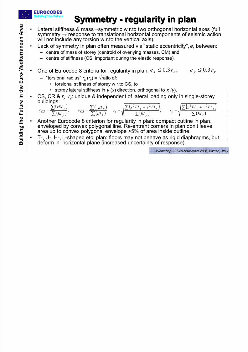
• Lateral stiffness & mass ~symmetric w.r.to two orthogonal horizontal axes (fullsymmetry → response to translational horizontal components of seismic actionwill not include any torsion w.r.to the vertical axis).
• Lack of symmetry in plan often measured via “static eccentricity”, e, between: – centre of mass of storey (centroid of overlying masses, CM) and
– centre of stiffness (CS, important during the elastic response).
• One of Eurocode 8 criteria for regularity in plan:
– “torsional radius” r x (r y) = √ratio of:
• torsional stiffness of storey w.r.to CS, to
• storey lateral stiffness in y ( x ) direction, orthogonal to x (y ).
• CS, CR & r x, r y: unique & independent of lateral loading only in single-storeybuildings:
• Another Eurocode 8 criterion for regularity in plan: compact outline in plan,enveloped by convex polygonal line. Re-entrant corners in plan don’t leavearea up to convex polygonal envelope >5% of area inside outline.
• T-, U-, H-, L-shaped etc. plan: floors may not behave as rigid diaphragms, but
deform in horizontal plane (increased uncertainty of response).
y y x x r er e 3.0;3.0 ≤≤
( )( )( )
∑
∑
∑
∑==
x
xCS
y
yCS
EI
yEI y
EI
xEI x ;
( )
( )
( )( )
∑
∑
∑
∑ +=
+=
x
x y y
y
x y x
EI
EI y EI xr
EI
EI y EI xr
2222
;
7/27/2019 Design of Buildings for Earthquake Resistance According to Eurocode 8 - Part 1
http://slidepdf.com/reader/full/design-of-buildings-for-earthquake-resistance-according-to-eurocode-8-part 6/53
EUROCODES
B u i l d i n g t h e F u t u r e i n t h e
E u r o - M e d i t e r r a n e a n A r e
a
Building the Future
Workshop - 27-29 November 2006, Varese, Italy
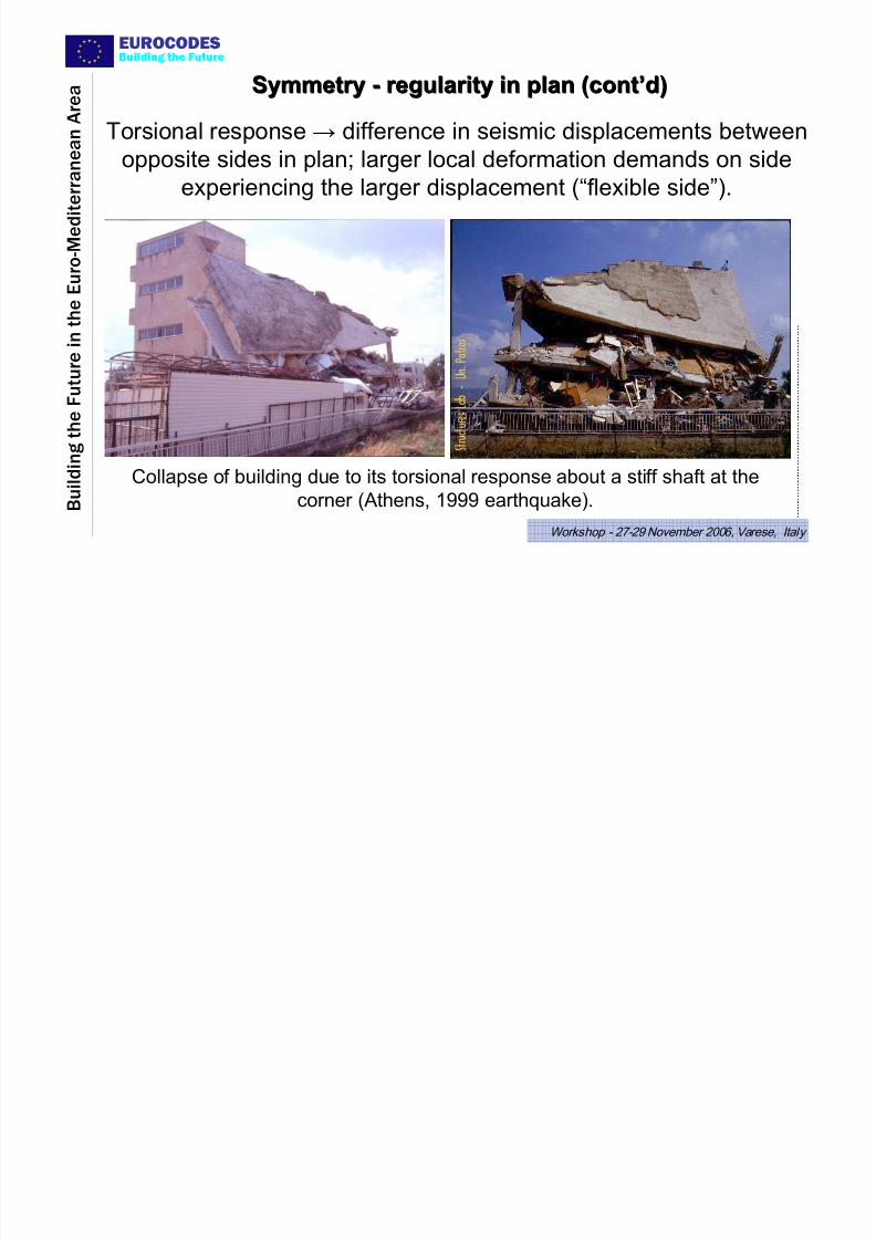
Torsional response → difference in seismic displacements between
opposite sides in plan; larger local deformation demands on side
experiencing the larger displacement (“flexible side”).
Collapse of building due to its torsional response about a stiff shaft at the
corner (Athens, 1999 earthquake).
SymmetrySymmetry -- regularity in plan (contregularity in plan (cont’’d)d)
7/27/2019 Design of Buildings for Earthquake Resistance According to Eurocode 8 - Part 1
http://slidepdf.com/reader/full/design-of-buildings-for-earthquake-resistance-according-to-eurocode-8-part 7/53
EUROCODES
B u i l d i n g t h e F u t u r e i n t h e
E u r o - M e d i t e r r a n e a n A r e
a
Building the Future
Workshop - 27-29 November 2006, Varese, Italy
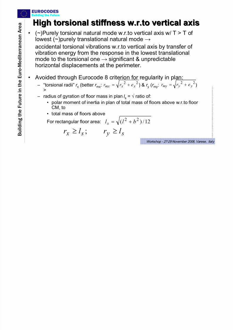
HighHigh torsionaltorsional stiffness w.r.to vertical axisstiffness w.r.to vertical axis• (~)Purely torsional natural mode w.r.to vertical axis w/ T > T of
lowest (~)purely translational natural mode →accidental torsional vibrations w.r.to vertical axis by transfer of
vibration energy from the response in the lowest translationalmode to the torsional one → significant & unpredictablehorizontal displacements at the perimeter.
• Avoided through Eurocode 8 criterion for regularity in plan:
– “torsional radii” r x (better r mx: ) & r y (r my: )>
– radius of gyration of floor mass in plan l s = √ ratio of:
• polar moment of inertia in plan of total mass of floors above w.r.to floor
CM, to• total mass of floors above
For rectangular floor area:
s y s x
l r l r ≥≥ ;
12/)( 22 bl l s +=
22 x xmx er r += 22
y ymy er r +=

7/27/2019 Design of Buildings for Earthquake Resistance According to Eurocode 8 - Part 1
http://slidepdf.com/reader/full/design-of-buildings-for-earthquake-resistance-according-to-eurocode-8-part 8/53
EUROCODES
B u i l d i n g t h e
F u t u r e i n t h e
E u r o - M e d i t e r r a n e a n A r e
a
Building the Future
Workshop - 27-29 November 2006, Varese, Italy
Means of providing torsional stiffness about a vertical axis:
Shear walls or strong frames at the perimeter
Arrangements of shear walls in plan:(a) preferable;
(b) drawbacks due to restraint of floors & difficulties of foundation at the corners;
(c) sensitive to failure of individual walls
HighHigh torsionaltorsional stiffness w.r.to vertical axis (contstiffness w.r.to vertical axis (cont’’d)d)
7/27/2019 Design of Buildings for Earthquake Resistance According to Eurocode 8 - Part 1
http://slidepdf.com/reader/full/design-of-buildings-for-earthquake-resistance-according-to-eurocode-8-part 9/53
EUROCODES
B u i l d i n g t h e
F u t u r e i n t h e
E u r o - M e d i t e r r a n e a n A r e
a
Building the Future
Workshop - 27-29 November 2006, Varese, Italy
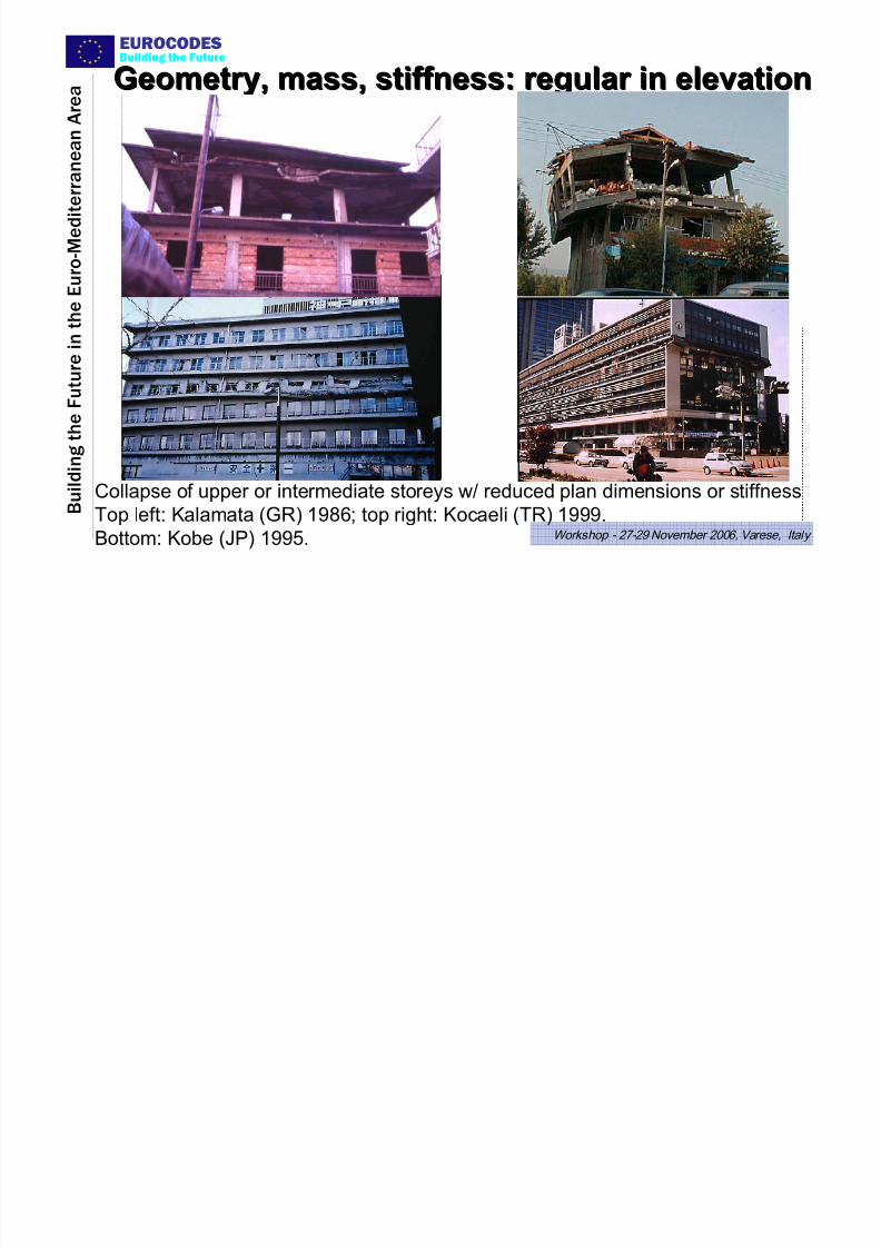
Geometry, mass, stiffness: regular in elevationGeometry, mass, stiffness: regular in elevation
Collapse of upper or intermediate storeys w/ reduced plan dimensions or stiffness
Top left: Kalamata (GR) 1986; top right: Kocaeli (TR) 1999.Bottom: Kobe (JP) 1995.
7/27/2019 Design of Buildings for Earthquake Resistance According to Eurocode 8 - Part 1
http://slidepdf.com/reader/full/design-of-buildings-for-earthquake-resistance-according-to-eurocode-8-part 10/53
EUROCODES
B u i l d i n g t h e
F u t u r e i n t h e
E u r o - M e d i t e r r a n e a n A r e
a
Building the Future
Workshop - 27-29 November 2006, Varese, Italy
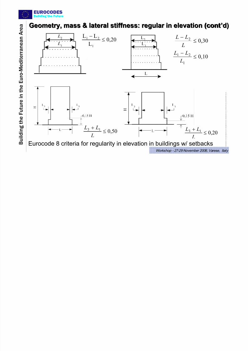
0,20L
LL
1
21 ≤−
0,302 ≤−
L
L L
0,101
21
≤
−
L
L L
0,5013 ≤+
L
L L0,2013 ≤
+
L
L L
Eurocode 8 criteria for regularity in elevation in buildings w/ setbacks
Geometry, mass & lateral stiffness: regular in elevation (contGeometry, mass & lateral stiffness: regular in elevation (cont’’d)d)

7/27/2019 Design of Buildings for Earthquake Resistance According to Eurocode 8 - Part 1
http://slidepdf.com/reader/full/design-of-buildings-for-earthquake-resistance-according-to-eurocode-8-part 11/53
EUROCODES
B u i l d i n g t h e
F u t u r e i n t h e
E u r o - M e d i t e r r a n e a n A r e
a
Building the Future
Workshop - 27-29 November 2006, Varese, Italy
Redundancy of structural systemRedundancy of structural system
In-plane bending of long floor diaphragms in
building with two strong walls at the 2 ends →intermediate columns overloaded, compared to
results of design w/ rigid diaphragm
• Provide large number of lateral-load resisting elements &alternative paths for earthquake resistance.
• Avoid systems w/ few large walls per horizontal direction,
especially in buildings long in plan:
V b
äto p
áu b dV
á1 b dV
1st yieldinganywhere
global plasticmechanism
V =design base shear bd
Eurocode 8: Bonus to system redundancy:qo proportional to α u/α 1 :
7/27/2019 Design of Buildings for Earthquake Resistance According to Eurocode 8 - Part 1
http://slidepdf.com/reader/full/design-of-buildings-for-earthquake-resistance-according-to-eurocode-8-part 12/53
EUROCODES
B u i l d i n g t h e
F u t u r e i n t h e
E u r o - M e d i t e r r a n e a n A r e
a
Building the Future
Workshop - 27-29 November 2006, Varese, Italy
Continuity of floor diaphragmsContinuity of floor diaphragms
• Need smooth/continuous path of forces, from the masses wherethey are generated due to inertia, to the foundation.
• Cast-in-situ reinforced concrete is the ideal structural materialfor earthquake resistant construction, compared to prefabricated
elements joined together at the site: the joints between suchelements are points of discontinuity.
• Floor diaphragms should have sufficient strength to transfer theinertia forces to the lateral-load-resisting system & be
adequately connected to it.• Large openings in floor slabs, due to internal patios, wide shaftsor stairways, etc. may disrupt continuity of force path, especiallyif such openings are next to large shear walls near or at the
perimeter.• Vertical elements of lateral-force resisting system should beconnected together, via combination of floor diaphragms &beams: – at all horizontal levels where significant masses are concentrated, and
– at foundation level.
7/27/2019 Design of Buildings for Earthquake Resistance According to Eurocode 8 - Part 1
http://slidepdf.com/reader/full/design-of-buildings-for-earthquake-resistance-according-to-eurocode-8-part 13/53
EUROCODES
B u i l d i n g t h e
F u t u r e i n t h e
E u r o - M e d i t e r r a n e a n A r e
a
Building the Future
Workshop - 27-29 November 2006, Varese, Italy
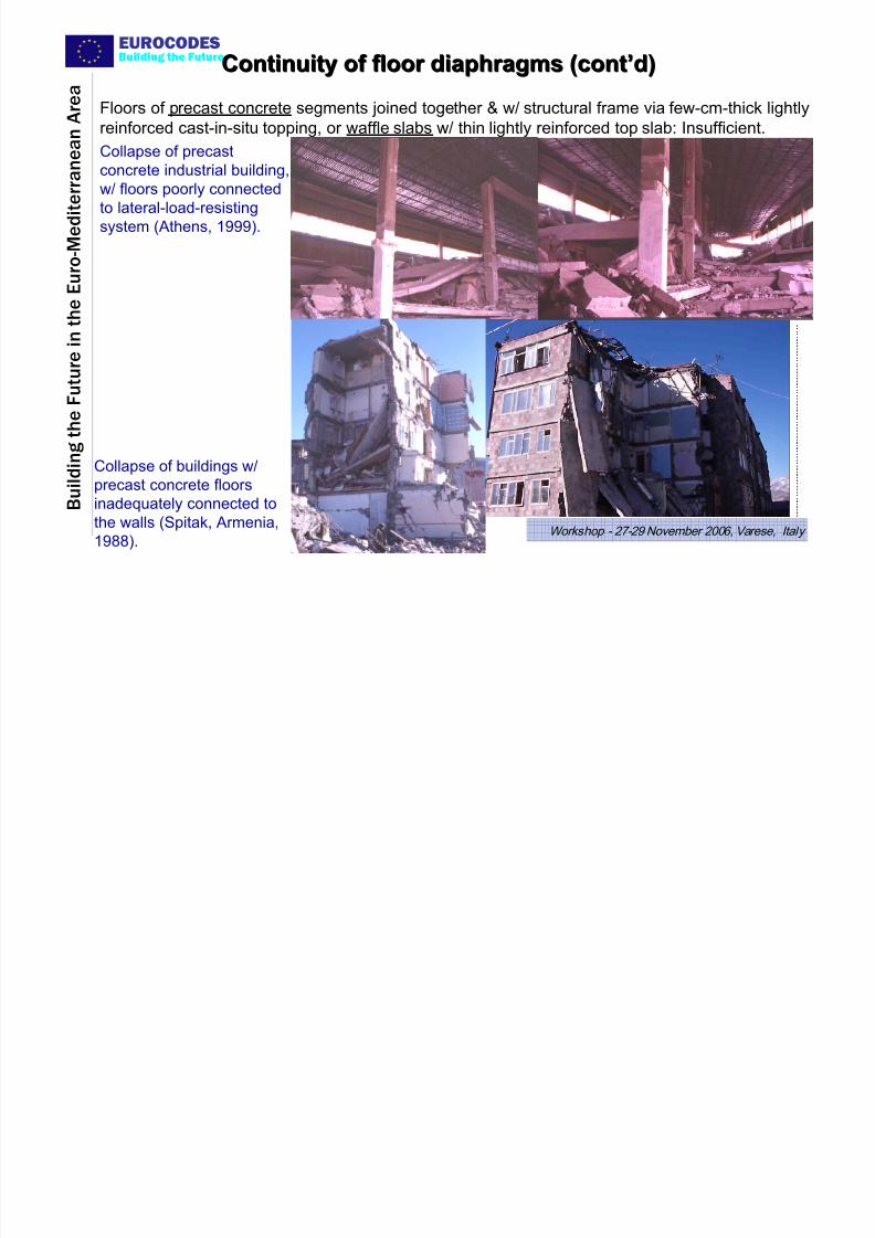
Floors of precast concrete segments joined together & w/ structural frame via few-cm-thick lightlyreinforced cast-in-situ topping, or waffle slabs w/ thin lightly reinforced top slab: Insufficient.
Collapse of buildings w/
precast concrete floors
inadequately connected to
the walls (Spitak, Armenia,
1988).
Continuity of floor diaphragms (contContinuity of floor diaphragms (cont’’d)d)
Collapse of precast
concrete industrial building,
w/ floors poorly connected
to lateral-load-resistingsystem (Athens, 1999).
7/27/2019 Design of Buildings for Earthquake Resistance According to Eurocode 8 - Part 1
http://slidepdf.com/reader/full/design-of-buildings-for-earthquake-resistance-according-to-eurocode-8-part 14/53
EUROCODES
B u i l d i n g t h e
F u t u r e i n t h e
E u r o - M e d i t e r r a n e a n A r e
a
Building the Future
Workshop - 27-29 November 2006, Varese, Italy
EC8 DESIGN CONCEPTS FOR SAFETYEC8 DESIGN CONCEPTS FOR SAFETY
UNDER DESIGN SEISMIC ACTIONUNDER DESIGN SEISMIC ACTION
1. Design for energy dissipation (normally through ductility): q>1.5
• Global ductility:
¾ Structure forced to remain straight in elevation through shear walls, bracing
system or strong columns (ΣMRc>1.3ΣMRb in frames):
• Local ductility:
¾ Plastic hinges detailed for ductility capacity derived from q-factor;
¾ Brittle failures prevented by overdesign/capacity design
• Capacity design of foundations & foundation elements:
¾ On the basis of overstrength of ductile elements of superstructure.
(Or: Foundation elements - including piles - designed & detailed for ductility)
2. Design w/o energy dissipation & ductility: q≤1.5 for overstrength;
design only according to EC2 - EC7 (Ductility Class “Low”– DCL)Only:
• for Low Seismicity (NDP; recommended: PGA on rock ≤0.08g)
• for superstructure of base-isolated buildings.

7/27/2019 Design of Buildings for Earthquake Resistance According to Eurocode 8 - Part 1
http://slidepdf.com/reader/full/design-of-buildings-for-earthquake-resistance-according-to-eurocode-8-part 15/53
EUROCODES
B u i l d i n g t h e
F u t u r e i n t h e
E u r o - M e d i t e r r a n e a n A r e
a
Building the Future
Workshop - 27-29 November 2006, Varese, Italy
ForceForce--based design for energybased design for energy--dissipation & ductility,dissipation & ductility,
to meet nto meet noo--(life(life--threateningthreatening--)collapse requirement under )collapse requirement under DesignDesign SeismicSeismic action:action:
• Structure allowed to develop significant inelastic deformations under design seismic action, provided that integrity of members & of thewhole is not endangered.
• Basis of force-based design for ductility:
– inelastic response spectrum of SDoF system having elastic-perfectly
plastic F -δ curve, in monotonic loading.• For given period, T , of elastic SDoF system, inelastic spectrum
relates:
– ratio q = F el/F y of peak force, F el, that would develop if the SDoF system
was linear-elastic, to its yield force, F y, (“behaviour factor”)
to
– maximum displacement demand of the inelastic SDOF system, δ max,
expressed as ratio to the yield displacement, δ y : displacement ductility
factor, μ δ = δ max/δ y
7/27/2019 Design of Buildings for Earthquake Resistance According to Eurocode 8 - Part 1
http://slidepdf.com/reader/full/design-of-buildings-for-earthquake-resistance-according-to-eurocode-8-part 16/53
EUROCODES
B u i l d i n g t h e
F u t u r e i n t h e
E u r o - M e d i t e r r a n e a n A r e
a
Building the Future
Workshop - 27-29 November 2006, Varese, Italy
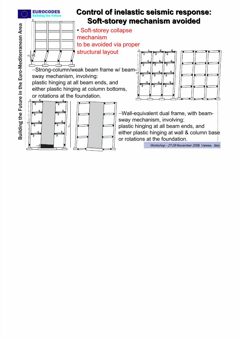
• Soft-storey collapsemechanism
to be avoided via proper
structural layout a a a a
a a a a
a a a a
a a a a
a a a a
a a a a
a a a a
a a a a
a a a a
a a a a
a a a a
a a a a
a a a a
a a a a
a a a a
a a a a
a a a a
a a a a
a a a a
a a a a
a a a a
a a a a
a a a a
a a a a
a a a a
a a a a
a a a a
a a a a
a a a a
a a a a
a a a a
a a a a
a a a a
a a a a
a a a a
a a a a
a a a a
a a a a
a a a a
a a a a
a a a a
a a a a
a a a a
a a a a
a a a a
a a a a
a a a a
a a a a
a a a a
a a a a
a a a a
a a a a
a a a a
a a a a
a a a a
a a a a
a a a a
a a a a
a a a a
a a a a
a a a a
a a a a
a a a a
a a a a
a a a a
a a a a
a a a a a
a a a a a
a a a a a
a a a a
a a a a
a a a a
a a a a
a a a a
a a a a
a a a a a
a a a a a
a a a a a
a a a a a
a a a a a
a a a a a
a a a a a
a a a a a
a a a a a
è
è
è
è
è
è
è
è
è
è
è
è
è
è
è
è
è
è
è
è
è
è
è
è
è
è
è
è
è
è
è
è
è
è
è
è
è
è
è
è
è
è
è
è
è
è
ä
è
H t o
t
a a a a
a a a a
a a a a
a a a a
a a a a
a a a a
a a a a
a a a a
a a a a
a a a a
a a a a
a a a a
a a a a
a a a a
a a a a
a a a a
a a a a
a a a a
a a a a
a a a a
a a a a
a a a a
a a a a
a a a a
a a a a
a a a a
a a a a
a a a a
a a a a
a a a a
a a a a
a a a a
a a a a
a a a a
a a a a
a a a a
a a a a
a a a a
a a a a
a a a a
a a a a
a a a a
a a a a
a a a a
a a a a
a a a a
a a a a
a a a a
a a a a
a a a a
a a a a
a a a a
a a a a
a a a a
a a a a
a a a a
a a a a
a a a a
a a a a
a a a a
a a a a
a a a a
a a a a
a a a a
a a a a
a a a a
a a a a
a a a a
a a a a
a a a a
a a a a
a a a a
a a a a
a a a a
a a a a
a a a a
a a a a
a a a a
a a a a
a a a a
a a a a
a a a a
a a a a
a a a a
a a a a
a a a a
a a a a
a a a a
a a a a
a a a a
a a a a
a a a a
a a a a
a a a a
a a a a
a a a a
a a a a
a a a a
a a a a
a a a a
a a a a
a a a a
a a a a a a a a
a a a a
a a a a
a a a a
a a a a
a a a a
a a a a
a a a a
a a a a
a a a a
a a a a
a a a a
a a a a
a a a a
a a a a
a a a a
a a a a
a a a a
a a a a
a a a a
a a a a
a a a a
a a a a
a a a a
a a a a
a a a a
a a a a
a a a a
a a a a
a a a a a
a a a a a
a a a a a
a a a a a
a a a a a
a a a a a
a a a a a a a a a a a a a a a a a a a a a a a a a a a a a a a a a a a a a a
a a a a a a a a a a a a a a a a a a a a a a a a a a a a a a a a a a a a a a
a a a a a a a a a a a a a a a a a a a a a a a a a a a a a a a a a a a a a a
a a a a a a a a a a a a a a a a a a a a a a a a a a a a a a a a a a a a a a
a a a a a a a a a a a a a a a a a a a a a a a a a a a a a a a a a a a a a a
a a a a a a a a a a a a a a a a a a a a a a a a a a a a a a a a a a a a a a
a a a a a a a a a a a a a a a a a a a a a a a a a a a a a a a a a a a a a a
è
è
è
è
è
è
è
è
è
è
è
è
è
è
è
è
è
è
è
è
è
è
è
è
è
è
è
è
è
è
è
è
è
H t o
t
ä
è
a a a a
a a a a
a a a a
a a a a
a a a a
a a a a
a a a a
a a a a
a a a a
a a a a
a a a a
a a a a
a a a a
a a a a
a a a a
a a a a
a a a a
a a a a
a a a a
a a a a
a a a a
a a a a
a a a a
a a a a
a a a a
a a a a
a a a a
a a a a
a a a a
a a a a
a a a a
a a a a
a a a a
a a a a
a a a a
a a a a
a a a a
a a a a
a a a a
a a a a
a a a a
a a a a
a a a a
a a a a
a a a a
a a a a
a a a a
a a a a
a a a a
a a a a
a a a a
a a a a
a a a a
a a a a
a a a a
a a a a
a a a a a
a a a a a
a a a a a
a a a a a
a a a a a
a a a a a
a a a a a
a a a a a
a a a a a
a a a a a
a a a a a
a a a a a
a a a a a
a a a a a
a a a a a
a a a a a
a a a a a
a a a a a
a a a a a
a a a a a
a a a a a
a a a a a
a a a a a
a a a a a
è st
ä
H st
−Strong-column/weak beam frame w/ beam-
sway mechanism, involving:
plastic hinging at all beam ends, andeither plastic hinging at column bottoms,
or rotations at the foundation.
−Wall-equivalent dual frame, with beam-sway mechanism, involving:
plastic hinging at all beam ends, and
either plastic hinging at wall & column base
or rotations at the foundation.
Control of inelastic seismic response:Control of inelastic seismic response:
SoftSoft--storey mechanism avoidedstorey mechanism avoided
7/27/2019 Design of Buildings for Earthquake Resistance According to Eurocode 8 - Part 1
http://slidepdf.com/reader/full/design-of-buildings-for-earthquake-resistance-according-to-eurocode-8-part 17/53
EUROCODES
B u i l d i n g t h e
F u t u r e i n t h e E u r o - M e d i t e r r a n e a n A r e a
Building the Future
Workshop - 27-29 November 2006, Varese, Italy
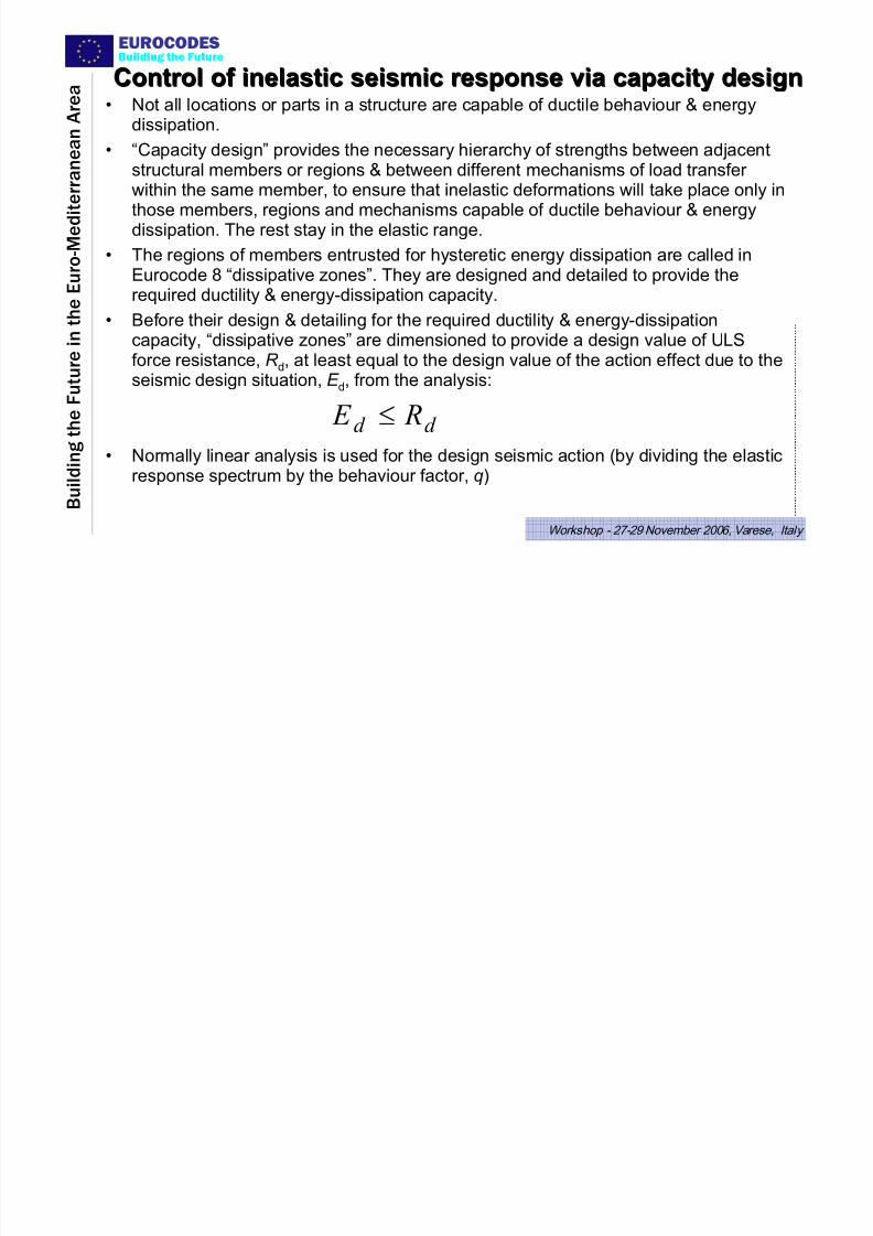
Control of inelastic seismic response via capacity designControl of inelastic seismic response via capacity design
• Not all locations or parts in a structure are capable of ductile behaviour & energydissipation.
• “Capacity design” provides the necessary hierarchy of strengths between adjacentstructural members or regions & between different mechanisms of load transfer within the same member, to ensure that inelastic deformations will take place only in
those members, regions and mechanisms capable of ductile behaviour & energydissipation. The rest stay in the elastic range.
• The regions of members entrusted for hysteretic energy dissipation are called inEurocode 8 “dissipative zones”. They are designed and detailed to provide therequired ductility & energy-dissipation capacity.
• Before their design & detailing for the required ductility & energy-dissipationcapacity, “dissipative zones” are dimensioned to provide a design value of ULSforce resistance, R d, at least equal to the design value of the action effect due to theseismic design situation, E d, from the analysis:
• Normally linear analysis is used for the design seismic action (by dividing the elasticresponse spectrum by the behaviour factor, q)
d d R E ≤
7/27/2019 Design of Buildings for Earthquake Resistance According to Eurocode 8 - Part 1
http://slidepdf.com/reader/full/design-of-buildings-for-earthquake-resistance-according-to-eurocode-8-part 18/53
EUROCODES
B u i l d i n g t h e
F u t u r e i n t h e E u r o - M e d i t e r r a n e a n A r e a
Building the Future
Workshop - 27-29 November 2006, Varese, Italy
EC8-PART 1: FOR ALL MATERIALS:• For Dissipative Structures (except masonry):
• Two Ductility Classes (DC):
¾DC H (High).
¾DC M (Medium).
• Differences in:¾q-values (usually q > 4 for DCH, 1.5 <q <4 for
DCM)
¾Local ductility requirements(ductility of materials or section, member detailing,
capacity design against brittle failure modes)
7/27/2019 Design of Buildings for Earthquake Resistance According to Eurocode 8 - Part 1
http://slidepdf.com/reader/full/design-of-buildings-for-earthquake-resistance-according-to-eurocode-8-part 19/53
EUROCODES
B u i l d i n g t h e
F u t u r e i n t h e E u r o - M e d i t
e r r a n e a n A r e a
Building the Future
Workshop - 27-29 November 2006, Varese, Italy
EC8-PART 1: FOR ALL MATERIALS:
• "Secondary seismic elements":
• Their contribution to resistance & stiffness for seismic actions neglected in design (& in linear
analysis model, too);
• Required to remain elastic under deformations dueto design seismic action.
• Designer free to assign elements to the class of
“secondary seismic elements”, provided that:¾Their total contribution to lateral stiffness ≤ 15%;
¾Regularity classification does not change.
7/27/2019 Design of Buildings for Earthquake Resistance According to Eurocode 8 - Part 1
http://slidepdf.com/reader/full/design-of-buildings-for-earthquake-resistance-according-to-eurocode-8-part 20/53
EUROCODES
B u i l d i n g t h e
F u t u r e i n t h e E u r o - M e d i t
e r r a n e a n A r e a
Building the Future
Workshop - 27-29 November 2006, Varese, Italy
CONCRETE & MASONRY BUILDINGSCONCRETE & MASONRY BUILDINGS
• Yield-point stiffness in analysis (50% of uncrackedsection EI):
• Reduction in design seismic forces vis-a-vis use of
full section EI
• Increase of displacements for drift-control & P-Δ
effects (governs sizes of frame members).
7/27/2019 Design of Buildings for Earthquake Resistance According to Eurocode 8 - Part 1
http://slidepdf.com/reader/full/design-of-buildings-for-earthquake-resistance-according-to-eurocode-8-part 21/53
EUROCODES
B u i l d i n g t h e
F u t u r e i n t h e E u r o - M e d i t
e r r a n e a n A r e a
Building the Future
Workshop - 27-29 November 2006, Varese, Italy
Implementation of EC8 seismic design philosophyImplementation of EC8 seismic design philosophy
• Damage limitation (storey drift ratio < 0.5-1%) under the damagelimitation earthquake (~50% of “design seismic action”), using 50%
of uncracked gross section stiffness.
• Member verification for the Ultimate Limit State (ULS) in bending
under the “design seismic action”, with elastic spectrum reduced by
the behaviour factor q.
• In frames or frame-equivalent dual systems: Fulfilment of strong
column/weak beam capacity design rule, with overstrength factor of 1.3 on beam strengths.
• Capacity design of members and joints in shear.
• Detailing of plastic hinge regions, on the basis of the value of the
curvature ductility factor that corresponds to the q-factor value.
7/27/2019 Design of Buildings for Earthquake Resistance According to Eurocode 8 - Part 1
http://slidepdf.com/reader/full/design-of-buildings-for-earthquake-resistance-according-to-eurocode-8-part 22/53
EUROCODES
B u i l d i n g t h e
F u t u r e i n t h e E u r o - M e d i t
e r r a n e a n A r e a
Building the Future
Workshop - 27-29 November 2006, Varese, Italy
EC8EC8--PART 1: DAMAGE LIMITATION CHECKPART 1: DAMAGE LIMITATION CHECK• Seismic action for “damage limitation”: NDP.
• Recommended for ordinary buildings: 10%/10yrs (95yr EQ);
• ~50% of “design seismic action” (475yr EQ).
• Interstorey drift ratio calculated for “damage limitation” action via “equal
displacement rule” (elastic response):
– <0.5% for brittle nonstructural elements attached to structure;
– <0.75% for ductile nonstructural elements attached to structure;
– < 1% for nonstructural elements not present or not interfering w/structural response (: damage limitation for structure).
• Concrete (& masonry):
– Elastic stiffness = 50% of uncracked gross-section stiffness.
• In concrete, steel or composite frames:damage limitation check governs member sizes.
7/27/2019 Design of Buildings for Earthquake Resistance According to Eurocode 8 - Part 1
http://slidepdf.com/reader/full/design-of-buildings-for-earthquake-resistance-according-to-eurocode-8-part 23/53
EUROCODES
B u i l d i n g t h e
F u t u r e i n t h e E u r o - M e d i t
e r r a n e a n A r e a
Building the Future
Workshop - 27-29 November 2006, Varese, Italy
ULS Verification of dissipative zonesULS Verification of dissipative zones• The regions of members entrusted for hysteretic energy dissipation -called in Eurocode 8 “dissipative zones” - are designed & detailed toprovide the required ductility & energy-dissipation capacity.
• Before their design & detailing for the required ductility & energy-dissipation capacity, “dissipative zones” are dimensioned to provide adesign value of ULS force resistance, R d, at least equal to the designvalue of the action effect due to the seismic design situation, E d, from
the analysis:
• Normally linear analysis is used for the design seismic action (bydividing the elastic response spectrum by the behaviour factor, q)
d d R E ≤
7/27/2019 Design of Buildings for Earthquake Resistance According to Eurocode 8 - Part 1
http://slidepdf.com/reader/full/design-of-buildings-for-earthquake-resistance-according-to-eurocode-8-part 24/53
EUROCODES
B u i l d i n g t h e
F u t u r e i n t h e E u r o - M e d i t
e r r a n e a n A r e a
Building the Future
Workshop - 27-29 November 2006, Varese, Italy
NDPNDP--partial factors for materials in ULS:partial factors for materials in ULS:
• Recommended:
• Use same values as for persistent & transient design
situations (i.e. in concrete buildings: γc=1.5,
γs=1.15);
7/27/2019 Design of Buildings for Earthquake Resistance According to Eurocode 8 - Part 1
http://slidepdf.com/reader/full/design-of-buildings-for-earthquake-resistance-according-to-eurocode-8-part 25/53
EUROCODES
B u i l d i n g t h e
F u t u r e i n t h e E u r o - M e d i t
e r r a n e a n A r e a
Building the Future
Workshop - 27-29 November 2006, Varese, Italy
column 1 column 1
beam 1 beam 2 beam 1 beam 2
column 2 column 2
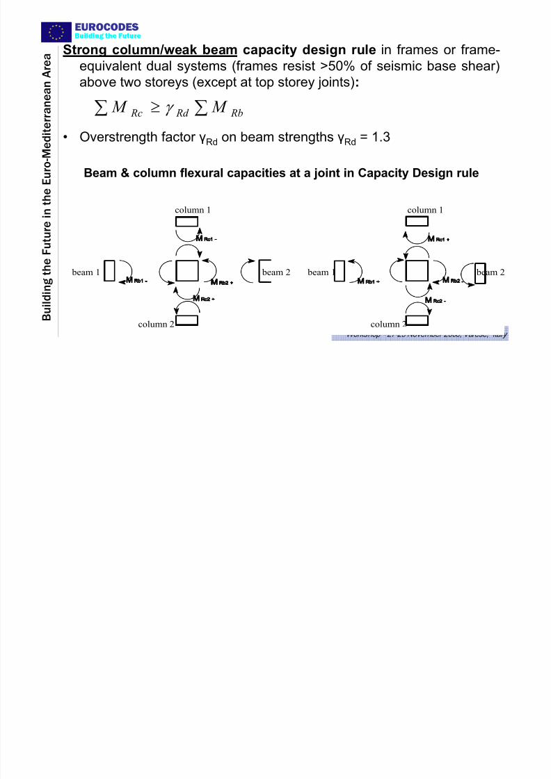
∑∑ ≥ Rb Rd Rc M M γ
Strong column/weak beam capacity design rule in frames or frame-
equivalent dual systems (frames resist >50% of seismic base shear)above two storeys (except at top storey joints):
• Overstrength factor γRd on beam strengths γRd = 1.3
Beam & column flexural capacities at a joint in Capacity Design rule
7/27/2019 Design of Buildings for Earthquake Resistance According to Eurocode 8 - Part 1
http://slidepdf.com/reader/full/design-of-buildings-for-earthquake-resistance-according-to-eurocode-8-part 26/53
EUROCODES
B u i l d i n g t h e
F u t u r e i n t h e E u r o - M e d i t
e r r a n e a n A r e a
Building the Future
Workshop - 27-29 November 2006, Varese, Italy
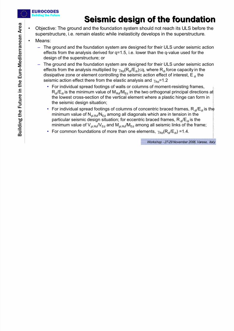
Seismic design of the foundationSeismic design of the foundation
• Objective: The ground and the foundation system should not reach its ULS before thesuperstructure, i.e. remain elastic while inelasticity develops in the superstructure.
• Means:
– The ground and the foundation system are designed for their ULS under seismic action
effects from the analysis derived for q=1.5, i.e. lower than the q-value used for the
design of the superstructure; or
– The ground and the foundation system are designed for their ULS under seismic action
effects from the analysis multiplied by γRd(Rdi/Edi)≤q, where Rdi force capacity in the
dissipative zone or element controlling the seismic action effect of interest, Edi the
seismic action effect there from the elastic analysis and γRd
=1.2
• For individual spread footings of walls or columns of moment-resisting frames,
Rdi/Edi is the minimum value of MRd/MEd in the two orthogonal principal directions at
the lowest cross-section of the vertical element where a plastic hinge can form in
the seismic design situation;
• For individual spread footings of columns of concentric braced frames, Rdi/Edi is theminimum value of Npl.Rd/NEd among all diagonals which are in tension in the
particular seismic design situation; for eccentric braced frames, Rdi/Edi is the
minimum value of Vpl.Rd/VEd and Mpl.Rd/MEd among all seismic links of the frame;
• For common foundations of more than one elements, γRd(Rdi/Edi) =1.4.
7/27/2019 Design of Buildings for Earthquake Resistance According to Eurocode 8 - Part 1
http://slidepdf.com/reader/full/design-of-buildings-for-earthquake-resistance-according-to-eurocode-8-part 27/53
EUROCODES
B u i l d i n g t h e
F u t u r e i n t h e E u r o - M e d i t
e r r a n e a n A r e a
Building the Future
Workshop - 27-29 November 2006, Varese, Italy
STRUCTURE OF EN1998-
1:20041 General
2 Performance Requirements and Compliance Criteria3 Ground Conditions and Seismic Action
4 Design of Buildings
5 Specific Rules for Concrete Buildings6 Specific Rules for Steel Buildings
7 Specific Rules for Steel-Concrete Composite Buildings
8 Specific Rules for Timber Buildings9 Specific Rules for Masonry Buildings
10 Base Isolation
EUROCODES
7/27/2019 Design of Buildings for Earthquake Resistance According to Eurocode 8 - Part 1
http://slidepdf.com/reader/full/design-of-buildings-for-earthquake-resistance-according-to-eurocode-8-part 28/53
EUROCODES
B u i l d i n g t h e
F u t u r e i n t h e E u r o - M e d i t
e r r a n e a n A r e a
Building the Future
Workshop - 27-29 November 2006, Varese, Italy
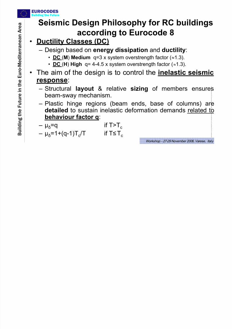
Seismic Design Philosophy for RC buildings
according to Eurocode 8• Ductility Classes (DC)
– Design based on energy dissipation and ductility:
• DC (M) Medium q=3 x system overstrength factor (≈1.3).
• DC (H) High q= 4-4.5 x system overstrength factor (≈1.3).
• The aim of the design is to control the inelastic seismic
response: – Structural layout & relative sizing of members ensuresbeam-sway mechanism.
– Plastic hinge regions (beam ends, base of columns) are
detailed to sustain inelastic deformation demands related tobehaviour factor q:
– μδ=q if Τ>Τc
– μδ=1+(q-1)T
c/T if Τ≤Τ
c
EUROCODES
7/27/2019 Design of Buildings for Earthquake Resistance According to Eurocode 8 - Part 1
http://slidepdf.com/reader/full/design-of-buildings-for-earthquake-resistance-according-to-eurocode-8-part 29/53
EUROCODES
B u i l d i n g t h e
F u t u r e i n t h e E u r o - M e d i t e r r a n e a n A r e a
Building the Future
Workshop - 27-29 November 2006, Varese, Italy
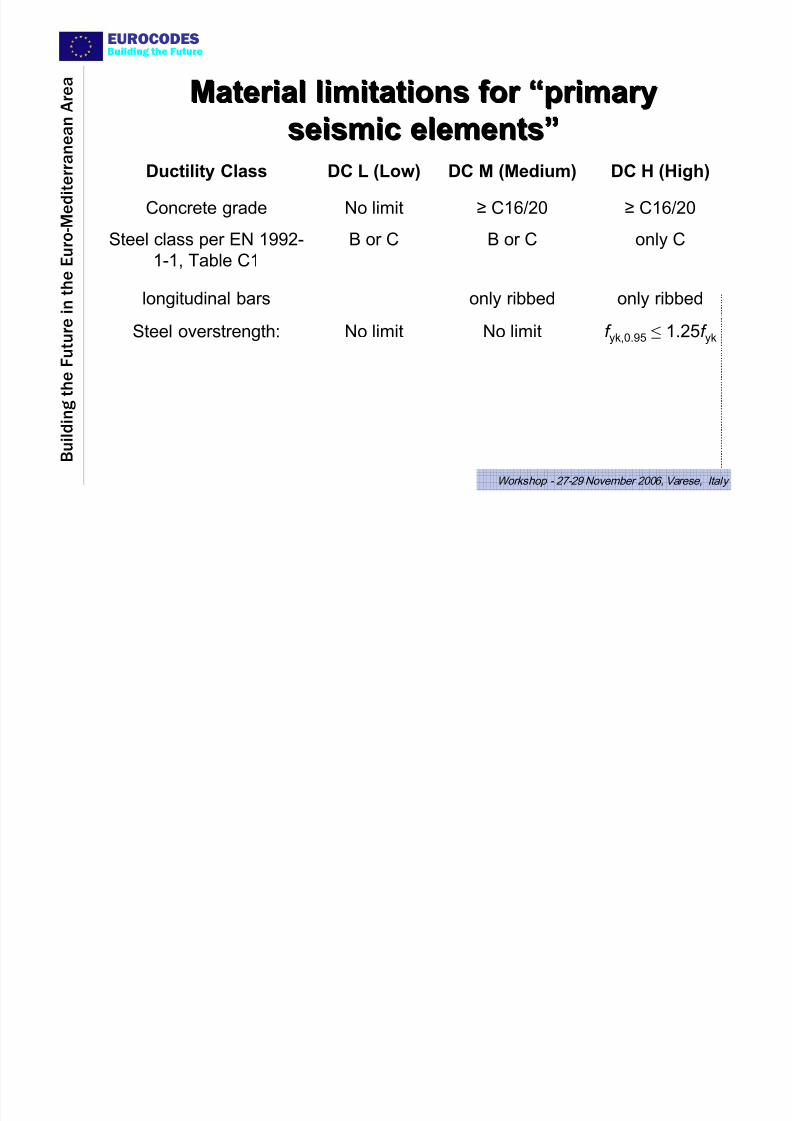
Material limitations for Material limitations for ““primaryprimaryseismic elementsseismic elements””
f yk,0.95 ≤ 1.25f ykNo limitNo limitSteel overstrength:
only ribbedonly ribbedlongitudinal bars
only CB or CB or CSteel class per EN 1992-
1-1, Table C1
≥ C16/20≥ C16/20No limitConcrete grade
DC H (High)DC M (Medium)DC L (Low)Ductility Class
EUROCODES B i l f b h i f t
7/27/2019 Design of Buildings for Earthquake Resistance According to Eurocode 8 - Part 1
http://slidepdf.com/reader/full/design-of-buildings-for-earthquake-resistance-according-to-eurocode-8-part 30/53
EUROCODES
B u i l d i n g t h e
F u t u r e i n t h e E u r o - M e d i t e r r a n e a n A r e a
Building the Future
Workshop - 27-29 November 2006, Varese, Italy
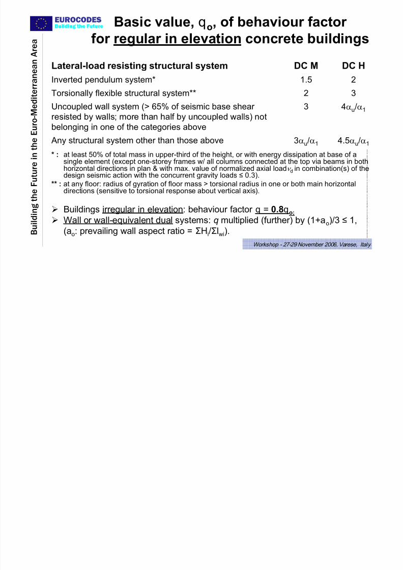
Basic value, qo, of behaviour factor
for regular in elevation concrete buildings
4αu/α13Uncoupled wall system (> 65% of seismic base shear
resisted by walls; more than half by uncoupled walls) not
belonging in one of the categories above
4.5αu/α13αu/α1 Any structural system other than those above
32Torsionally flexible structural system**
21.5Inverted pendulum system*
DC HDC MLateral-load resisting structural system
* : at least 50% of total mass in upper-third of the height, or with energy dissipation at base of asingle element (except one-storey frames w/ all columns connected at the top via beams in bothhorizontal directions in plan & with max. value of normalized axial loadν d in combination(s) of thedesign seismic action with the concurrent gravity loads ≤ 0.3).
** : at any floor: radius of gyration of floor mass > torsional radius in one or both main horizontal
directions (sensitive to torsional response about vertical axis).
¾ Buildings irregular in elevation: behaviour factor q = 0.8qo;
¾ Wall or wall-equivalent dual systems: q multiplied (further) by (1+aο)/3 ≤ 1,
(aο: prevailing wall aspect ratio = ΣHi/Σlwi).
EUROCODES
7/27/2019 Design of Buildings for Earthquake Resistance According to Eurocode 8 - Part 1
http://slidepdf.com/reader/full/design-of-buildings-for-earthquake-resistance-according-to-eurocode-8-part 31/53
EUROCODES
B u i l d i n g t h e
F u t u r e i n t h
e E u r o - M e d i t e r r a n e a n A r
e a
Building the Future
Workshop - 27-29 November 2006, Varese, Italy
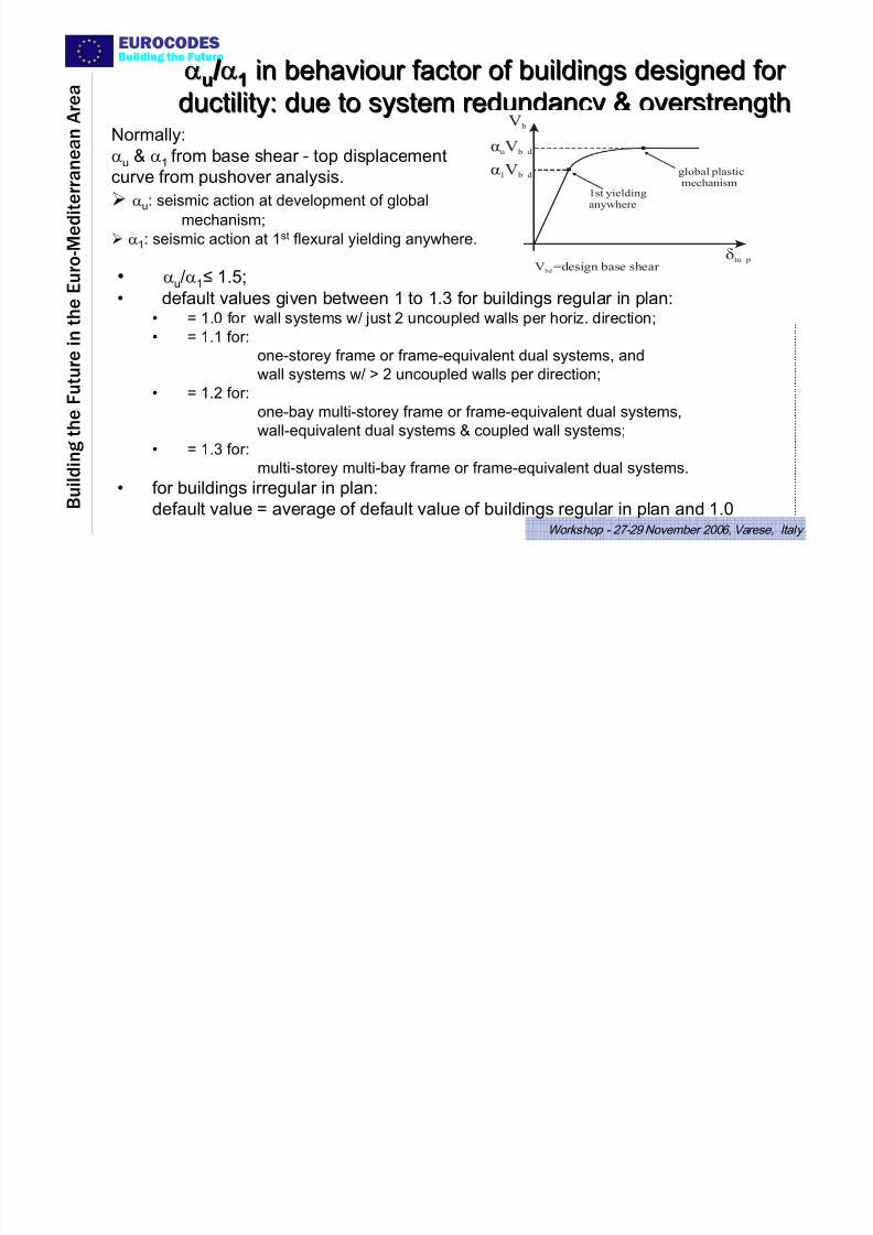
αuu / /α11 in bin behaviour factor of buildings designed for ehaviour factor of buildings designed for
ductility: due to system redundancy & overstrengthductility: due to system redundancy & overstrengthV b
äto p
áu b dV
á1 b dV
1st yieldinganywhere
global plasticmechanism
V =design base shear bd
Normally:
αu & α1 from base shear - top displacement
curve from pushover analysis.
¾ αu
: seismic action at development of global
mechanism;
¾ α1: seismic action at 1st flexural yielding anywhere.
• αu/α1≤ 1.5;
• default values given between 1 to 1.3 for buildings regular in plan:• = 1.0 for wall systems w/ just 2 uncoupled walls per horiz. direction;• = 1.1 for:
one-storey frame or frame-equivalent dual systems, and
wall systems w/ > 2 uncoupled walls per direction;
• = 1.2 for:
one-bay multi-storey frame or frame-equivalent dual systems,wall-equivalent dual systems & coupled wall systems;
• = 1.3 for:
multi-storey multi-bay frame or frame-equivalent dual systems.
• for buildings irregular in plan:
default value = average of default value of buildings regular in plan and 1.0
EUROCODES
7/27/2019 Design of Buildings for Earthquake Resistance According to Eurocode 8 - Part 1
http://slidepdf.com/reader/full/design-of-buildings-for-earthquake-resistance-according-to-eurocode-8-part 32/53
EUROCODES
B u i l d i n g t h e
F u t u r e i n t h
e E u r o - M e d i t e r r a n e a n A r
e a
Building the Future
Workshop - 27-29 November 2006, Varese, Italy
Capacity design of members,Capacity design of members,
against preagainst pre--emptive shear failureemptive shear failure
EUROCODES I BeamsI Beams
7/27/2019 Design of Buildings for Earthquake Resistance According to Eurocode 8 - Part 1
http://slidepdf.com/reader/full/design-of-buildings-for-earthquake-resistance-according-to-eurocode-8-part 33/53
EUROCODES
B u i l d i n g t h e
F u t u r e i n t h
e E u r o - M e d i t e r r a n e a n A r
e a
Building the Future
Workshop - 27-29 November 2006, Varese, Italy
)x(Vl
M
M;1minM
M
M;1minM
)x(Vmax oq,gcl
j bRd,
cRd, bjRd,
i bRd,
cRd, biRd,Rd
di, ψ
γ
+
+−
+⎥
⎥
⎦
⎤
⎢
⎢
⎣
⎡
⎟⎟
⎠
⎞⎜⎜
⎝
⎛ +⎟
⎟
⎠
⎞⎜⎜
⎝
⎛
= ∑
∑
∑
∑
)x(Vl
M
M;1minM
M
M;1minM
)x(Vmin oq,gcl
j bRd,
cRd, bjRd,
i bRd,
cRd, biRd,Rd
di, ψ
γ
+
−+
+⎥⎥
⎦
⎤
⎢⎢
⎣
⎡
⎟⎟
⎠
⎞⎜⎜
⎝
⎛ +⎟
⎟
⎠
⎞⎜⎜
⎝
⎛
−= ∑
∑
∑
∑
)(max
)(min
di,
di,
i
i
i xV
xV =ζ
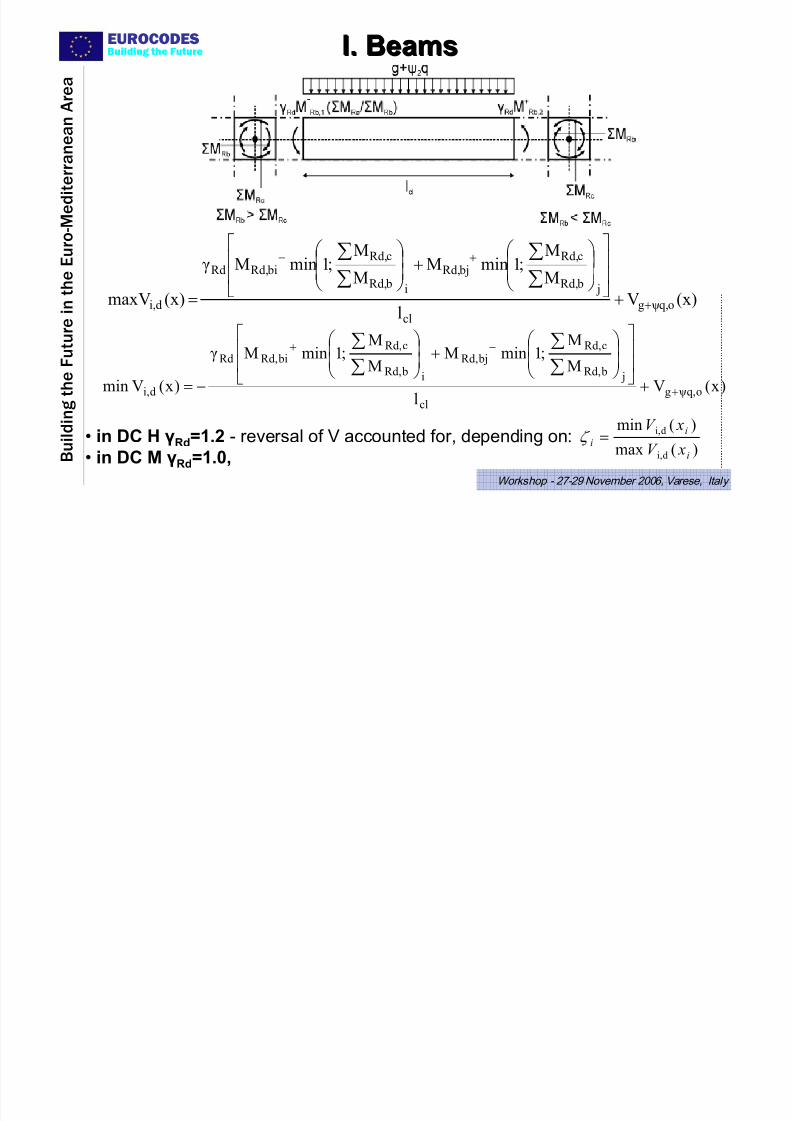
I. BeamsI. Beams
• in DC H γRd=1.2 - reversal of V accounted for, depending on:
• in DC M γRd
=1.0,
EUROCODES
7/27/2019 Design of Buildings for Earthquake Resistance According to Eurocode 8 - Part 1
http://slidepdf.com/reader/full/design-of-buildings-for-earthquake-resistance-according-to-eurocode-8-part 34/53
EUROCODES
B u i l d i n g t h e
F u t u r e i n t h
e E u r o - M e d i t e r r a n e a n A r
e a
Building the Future
Workshop - 27-29 November 2006, Varese, Italy
cl
c Rd c Rd
Rd CDh
M M V
_ 2,1, +
=+
+ γ cl
c Rd c Rd
Rd CDh
M M V
+−− += 2,1,γ
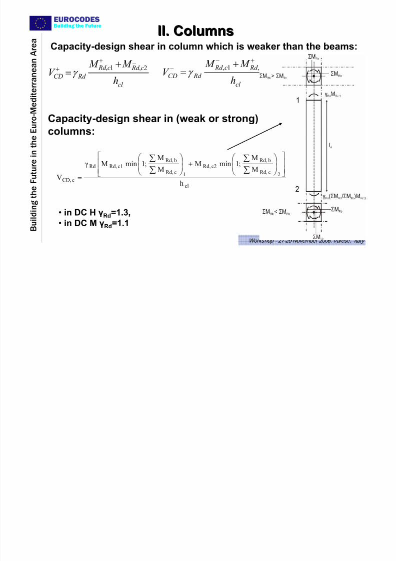
Capacity-design shear in column which is weaker than the beams:
Capacity-design shear in (weak or strong)
columns:
cl
2cRd,
bRd,c2Rd,
1cRd,
bRd,c1Rd,Rd
cCD,h
M
M;1minM
M
M;1minM
V⎥⎥⎦
⎤
⎢⎢⎣
⎡
⎟⎟ ⎠
⎞⎜⎜⎝
⎛ +⎟
⎟ ⎠
⎞⎜⎜⎝
⎛
=∑∑
∑∑
γ
II. ColumnsII. Columns
• in DC H γRd=1.3,
• in DC M γRd=1.1
EUROCODES
7/27/2019 Design of Buildings for Earthquake Resistance According to Eurocode 8 - Part 1
http://slidepdf.com/reader/full/design-of-buildings-for-earthquake-resistance-according-to-eurocode-8-part 35/53
EUROCODES
B u i l d i n g t h e
F u t u r e i n t h
e E u r o - M e d i t e r r a n e a n A r
e a
Building the Future
Workshop - 27-29 November 2006, Varese, Italy
q M M
V V
Edo
Rdo Rd '
Ed
Ed ≤⎟⎟ ⎠ ⎞⎜⎜
⎝ ⎛ == γ ε
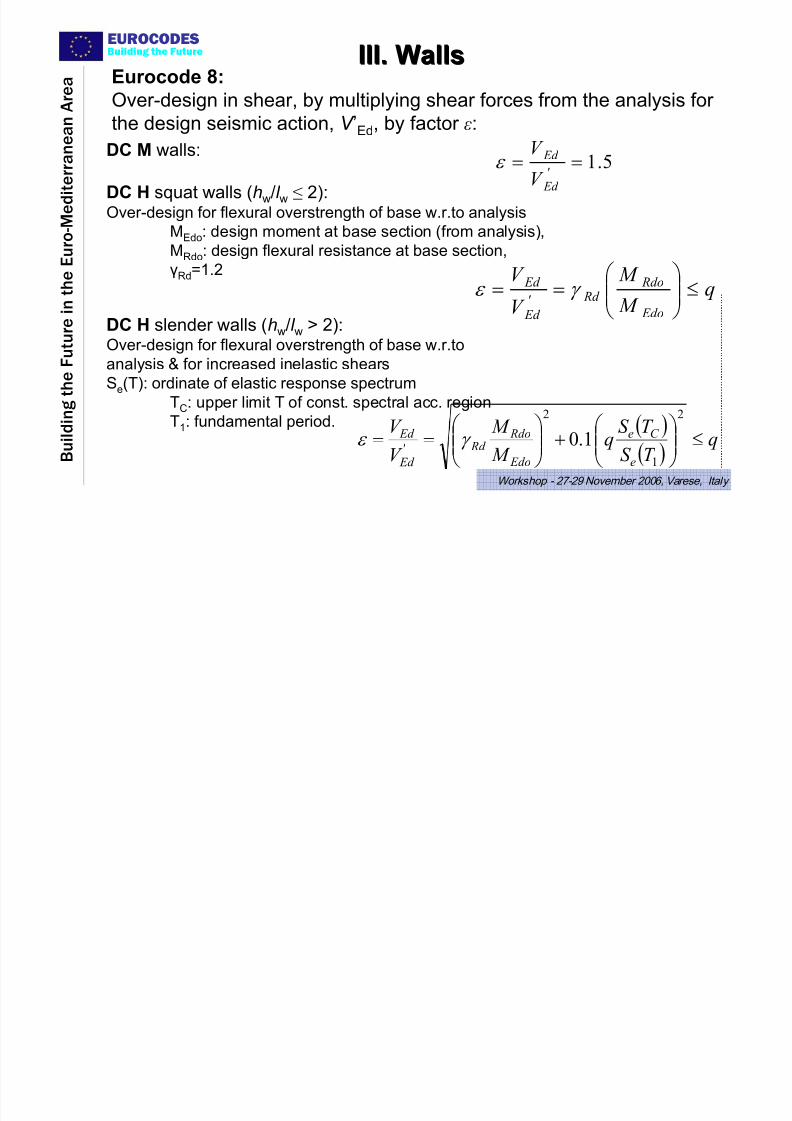
DC H squat walls (hw/l w ≤ 2):Over-design for flexural overstrength of base w.r.to analysis
MEdo: design moment at base section (from analysis),
MRdo: design flexural resistance at base section,
γRd=1.2
( )( )
qT S
T S q
M
M
V
V
e
C e
Edo
Rdo Rd '
Ed
Ed ≤⎟⎟
⎠
⎞⎜⎜
⎝
⎛ +⎟⎟
⎠
⎞⎜⎜
⎝
⎛ ==
2
1
2
1.0γ ε
DC H slender walls (hw/l w > 2):Over-design for flexural overstrength of base w.r.to
analysis & for increased inelastic shears
Se(T): ordinate of elastic response spectrum
TC: upper limit T of const. spectral acc. region
T1: fundamental period.
5.1=='
Ed
Ed
V
V ε
DC M walls:
III. WallsIII. WallsEurocode 8:
Over-design in shear, by multiplying shear forces from the analysis for the design seismic action, V ’Ed, by factor ε:
EUROCODES
7/27/2019 Design of Buildings for Earthquake Resistance According to Eurocode 8 - Part 1
http://slidepdf.com/reader/full/design-of-buildings-for-earthquake-resistance-according-to-eurocode-8-part 36/53
B u i l d i n g t h e
F u t u r e i n t h
e E u r o - M e d i t e r r a n e a n A r
e a
Building the Future
Workshop - 27-29 November 2006, Varese, Italy
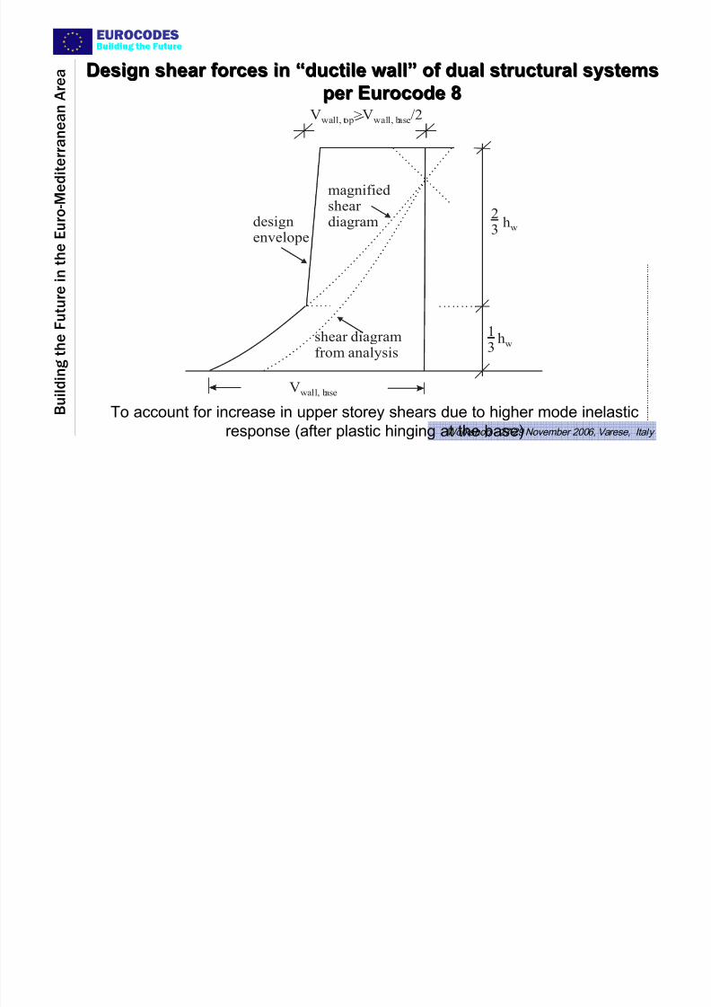
magnifiedshear diagram
shear diagramfrom analysis
Vwall, base
V >V /2wall, top wall, base
23
13
designenvelope
hw
hw
To account for increase in upper storey shears due to higher mode inelastic
response (after plastic hinging at the base)
Design shear forces inDesign shear forces in ““ductile wallductile wall”” of dual structural systemsof dual structural systems
per Eurocode 8per Eurocode 8
EUROCODES
7/27/2019 Design of Buildings for Earthquake Resistance According to Eurocode 8 - Part 1
http://slidepdf.com/reader/full/design-of-buildings-for-earthquake-resistance-according-to-eurocode-8-part 37/53
B u i l d i n g t h e
F u t u r e i n t h
e E u r o - M e d i t e r r a n e a n A r
e a
Building the Future
Workshop - 27-29 November 2006, Varese, Italy
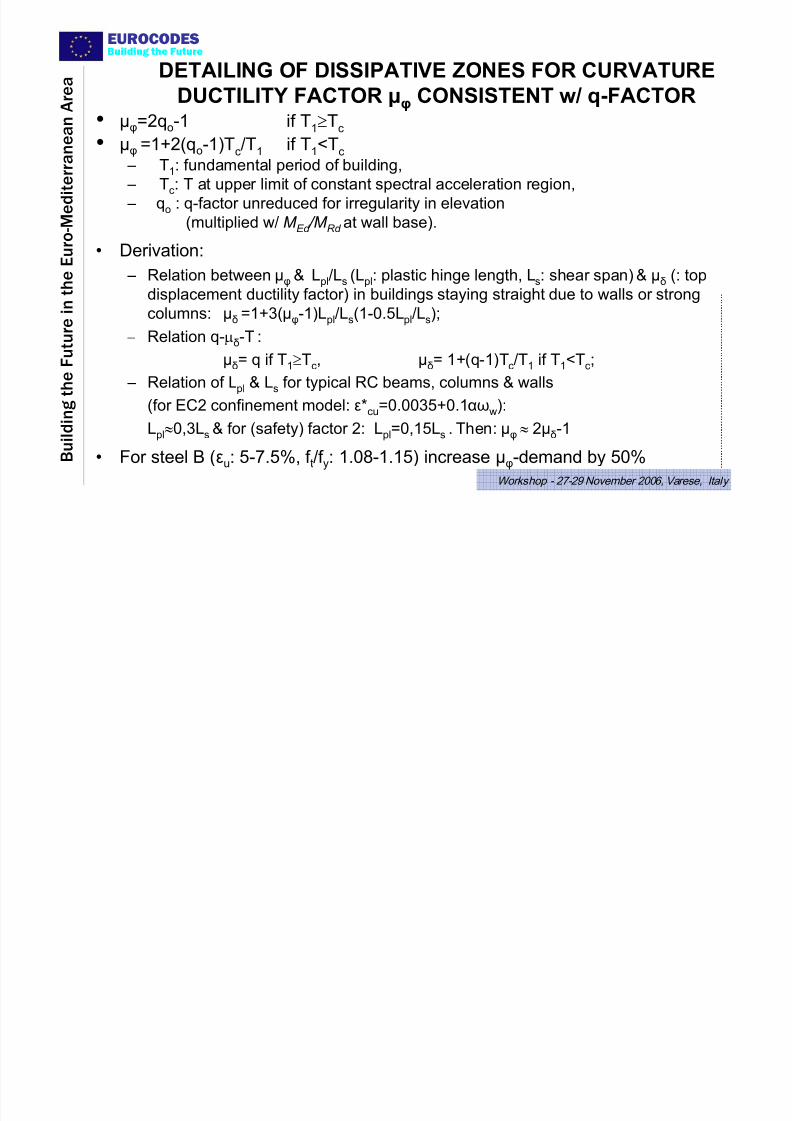
DETAILING OF DISSIPATIVE ZONES FOR CURVATURE
DUCTILITY FACTOR μφ CONSISTENT w/ q-FACTOR• μφ=2qo-1 if T1≥Tc
• μφ =1+2(qo-1)Tc/T1 if T1<Tc
– T1: fundamental period of building,
– Tc: T at upper limit of constant spectral acceleration region, – qo : q-factor unreduced for irregularity in elevation
(multiplied w/ M Ed /M Rd at wall base).
• Derivation:
– Relation between μφ
& Lpl/L
s(L
pl: plastic hinge length, L
s: shear span) & μ
δ(: top
displacement ductility factor) in buildings staying straight due to walls or strong
columns: μδ =1+3(μφ-1)Lpl/Ls(1-0.5Lpl/Ls);
– Relation q-μδ-T :
μδ= q if T1≥Tc, μδ= 1+(q-1)Tc/T1 if T1<Tc;
– Relation of Lpl & Ls for typical RC beams, columns & walls
(for EC2 confinement model: ε*cu=0.0035+0.1αωw):
Lpl≈0,3Ls & for (safety) factor 2: Lpl=0,15Ls . Then: μφ ≈ 2μδ-1
• For steel B (εu: 5-7.5%, f t/f y: 1.08-1.15) increase μφ-demand by 50%
EUROCODESB ildi h F
7/27/2019 Design of Buildings for Earthquake Resistance According to Eurocode 8 - Part 1
http://slidepdf.com/reader/full/design-of-buildings-for-earthquake-resistance-according-to-eurocode-8-part 38/53
B u i l d i n g t h e
F u t u r e i n t h
e E u r o - M e d i t e r r a n e a n A r
e a
Building the Future
Workshop - 27-29 November 2006, Varese, Italy
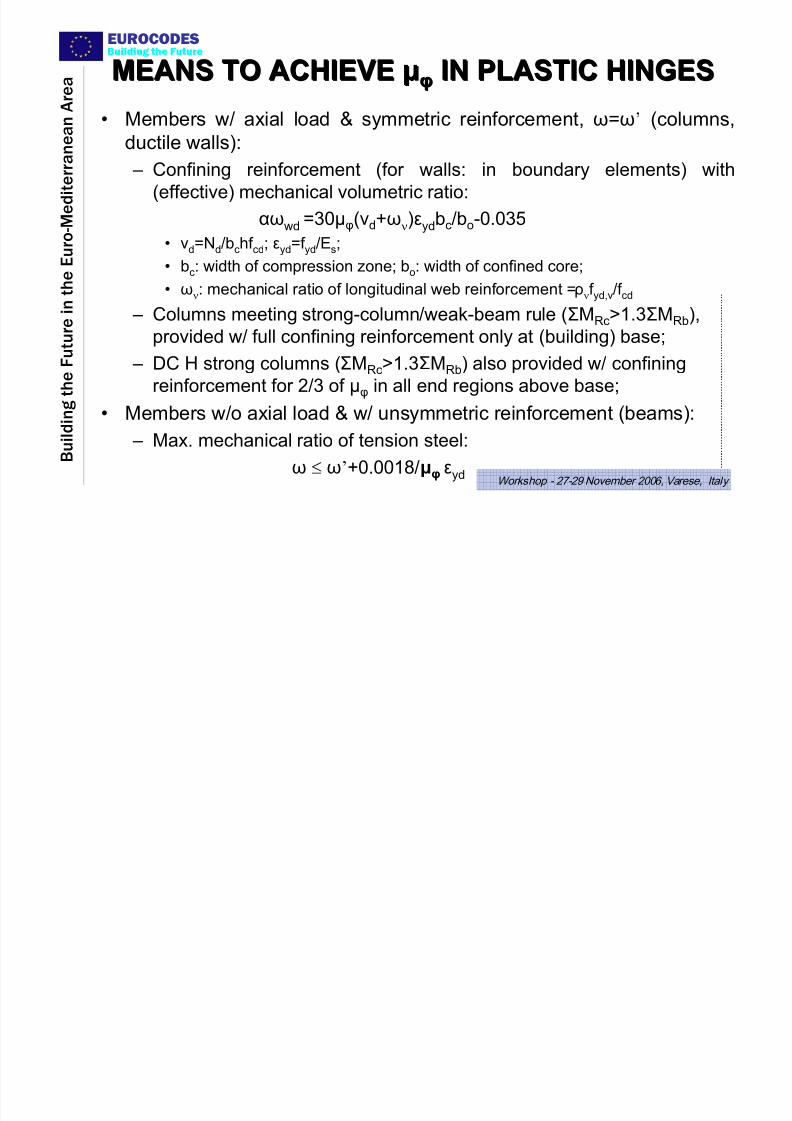
MEANS TO ACHIEVEMEANS TO ACHIEVE μμφφ IN PLASTIC HINGESIN PLASTIC HINGES
• Members w/ axial load & symmetric reinforcement, ω=ω’ (columns,
ductile walls):
– Confining reinforcement (for walls: in boundary elements) with
(effective) mechanical volumetric ratio:αωwd =30μφ(νd+ων)εydbc/bo-0.035
• νd=Nd/bchf cd; εyd=f yd/Es;
• bc: width of compression zone; bo: width of confined core;
• ων: mechanical ratio of longitudinal web reinforcement =ρνf yd,v/f cd
– Columns meeting strong-column/weak-beam rule (ΣMRc>1.3ΣMRb),
provided w/ full confining reinforcement only at (building) base;
– DC H strong columns (ΣMRc>1.3ΣMRb) also provided w/ confining
reinforcement for 2/3 of μφ in all end regions above base;
• Members w/o axial load & w/ unsymmetric reinforcement (beams):
– Max. mechanical ratio of tension steel:
ω ≤ ω’+0.0018/μφ εyd
EUROCODESB ildi g th F t TYPES OF DISSIPATIVE WALLSTYPES OF DISSIPATIVE WALLS

7/27/2019 Design of Buildings for Earthquake Resistance According to Eurocode 8 - Part 1
http://slidepdf.com/reader/full/design-of-buildings-for-earthquake-resistance-according-to-eurocode-8-part 39/53
B u i l d i n g t h e
F u t u r e i n t h
e E u r o - M e d i t e r r a n e a n A r
e a
Building the Future
Workshop - 27-29 November 2006, Varese, Italy
TYPES OF DISSIPATIVE WALLSTYPES OF DISSIPATIVE WALLS• Ductile wall:
¾ Fixed at base, to prevent rotation there w.r.to rest of structural system.¾ Designed & detailed to dissipate energy only in flexural plastic hinge just
above the base.
• Large lightly-reinforced wall (only for DC M):
¾Wall with horizontal dimension lw≥ 4m, expected to develop limited crackingor inelastic behaviour, but to transform seismic energy to potential energy(uplift of masses) & energy dissipated in the soil by rigid-body rocking, etc.
¾ Due to its dimensions, or lack-of-fixity at base wall cannot be designed for energy dissipation in plastic hinge at the base.
EUROCODESBuilding the Future
7/27/2019 Design of Buildings for Earthquake Resistance According to Eurocode 8 - Part 1
http://slidepdf.com/reader/full/design-of-buildings-for-earthquake-resistance-according-to-eurocode-8-part 40/53
B u i l d i n g t h e
F u t u r e i n t h
e E u r o - M e d i t e r r a n e a n A r
e a
Building the Future
Workshop - 27-29 November 2006, Varese, Italy
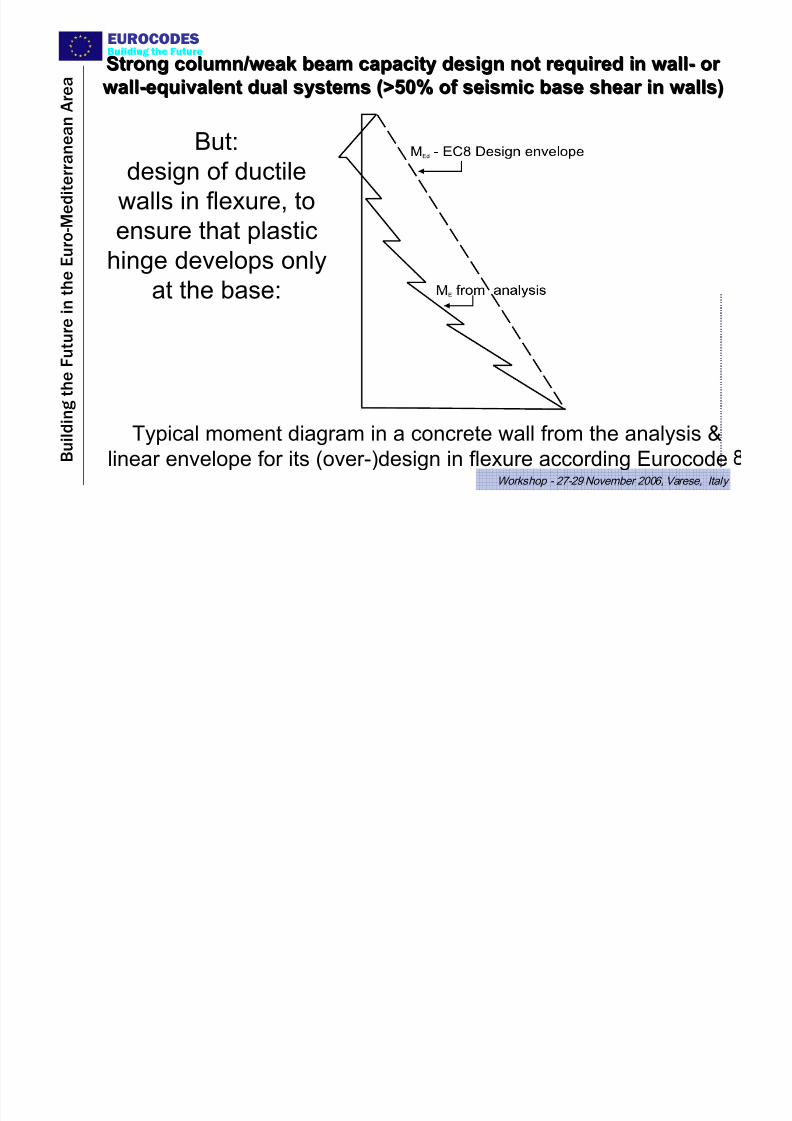
Typical moment diagram in a concrete wall from the analysis &
linear envelope for its (over-)design in flexure according Eurocode
But:
design of ductile
walls in flexure, toensure that plastic
hinge develops only
at the base:
Strong column/weak beam capacity design not required iStrong column/weak beam capacity design not required in walln wall-- or or
wallwall--equivalent dual systems (>50% of seismic base shear in walls)equivalent dual systems (>50% of seismic base shear in walls)
EUROCODESBuilding the Future DESIGN & DETAILING OF DUCTILE WALLS
7/27/2019 Design of Buildings for Earthquake Resistance According to Eurocode 8 - Part 1
http://slidepdf.com/reader/full/design-of-buildings-for-earthquake-resistance-according-to-eurocode-8-part 41/53
B u i l d i n g t h e
F u t u r e i n t h
e E u r o - M e d i t e r r a n e a n A r
e a
Building the Future
Workshop - 27-29 November 2006, Varese, Italy
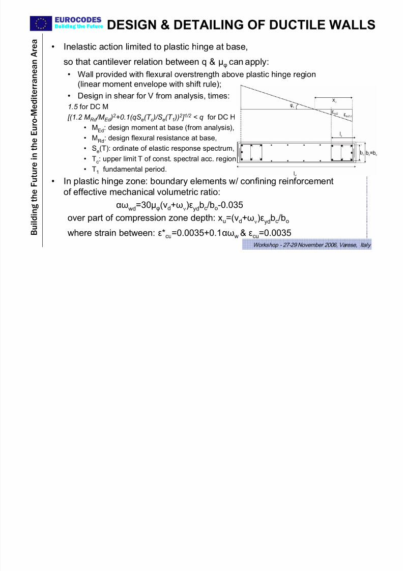
DESIGN & DETAILING OF DUCTILE WALLS
• Inelastic action limited to plastic hinge at base,
so that cantilever relation between q & μφ can apply:
• Wall provided with flexural overstrength above plastic hinge region
(linear moment envelope with shift rule);
• Design in shear for V from analysis, times:1.5 for DC M
[(1.2 M Rd /M Ed )2 +0.1(qSe(T c )/Se(T 1 ))
2 ] 1/2 < q for DC H
• MEd: design moment at base (from analysis),
• MRd: design flexural resistance at base,
• Se(T): ordinate of elastic response spectrum,
• Tc: upper limit T of const. spectral acc. region
• T1 fundamental period.
• In plastic hinge zone: boundary elements w/ confining reinforcement
of effective mechanical volumetric ratio:αωwd=30μφ(νd+ων)εydbc/bo-0.035
over part of compression zone depth: xu=(νd+ων)εydbc/bo
where strain between: ε*cu=0.0035+0.1αωw & εcu=0.0035
EUROCODESBuilding the Future LARGE LIGHTLY REINFORCED WALLS
7/27/2019 Design of Buildings for Earthquake Resistance According to Eurocode 8 - Part 1
http://slidepdf.com/reader/full/design-of-buildings-for-earthquake-resistance-according-to-eurocode-8-part 42/53
B u i l d i n g t h e
F u t u r e i n t h
e E u r o - M e d i t e r r a n e a n A r e a
Building the Future
Workshop - 27-29 November 2006, Varese, Italy
LARGE LIGHTLY REINFORCED WALLS• Wall system classified as one of large lightly reinforced walls if,
in horizontal direction of interest: – at least 2 walls with lw>4 m, supporting together >20% of gravity load above
(: sufficient no. of walls / floor area & significant uplift of masses); if just one wall, q=2
– fundamental period T1<0.5 s for fixity at base against rotation (: wall aspect ratio low)
• Systems of large lightly reinforced walls:Æ only DC M (q=3);
Æ special (less demanding) dimensioning & detailing.
• Rationale: For large walls, minimum reinforcement of ductile walls implies:
• very high cost;
• flexural overstrength that cannot be transmitted to ground.
On the other hand, large lightly reinforced walls:
• preclude (collapse due to) storey mechanism,
• minimize nonstructural damage,
• have shown satisfactory performance in strong EQs.
• If structural system does not qualify as one of large lightly reinforced
walls, all its walls designed & detailed as ductile walls.
EUROCODESBuilding the Future DESIGN & DETAILINGDESIGN & DETAILING
7/27/2019 Design of Buildings for Earthquake Resistance According to Eurocode 8 - Part 1
http://slidepdf.com/reader/full/design-of-buildings-for-earthquake-resistance-according-to-eurocode-8-part 43/53
B u i l d i n g t h e
F u t u r e i n t h
e E u r o - M e d i
t e r r a n e a n A r e a
Building the Future
Workshop - 27-29 November 2006, Varese, Italy
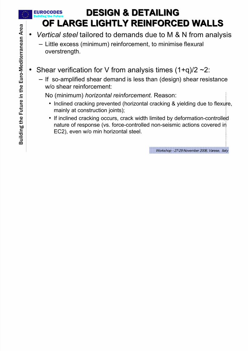
OF LARGE LIGHTLY REINFORCED WALLSOF LARGE LIGHTLY REINFORCED WALLS
• Vertical steel tailored to demands due to M & N from analysis
– Little excess (minimum) reinforcement, to minimise flexural
overstrength.
• Shear verification for V from analysis times (1+q)/2 ~2:
– If so-amplified shear demand is less than (design) shear resistance
w/o shear reinforcement:No (minimum) horizontal reinforcement. Reason:
• Inclined cracking prevented (horizontal cracking & yielding due to flexure,
mainly at construction joints);
• If inclined cracking occurs, crack width limited by deformation-controllednature of response (vs. force-controlled non-seismic actions covered in
EC2), even w/o min horizontal steel.
EUROCODESBuilding the Future
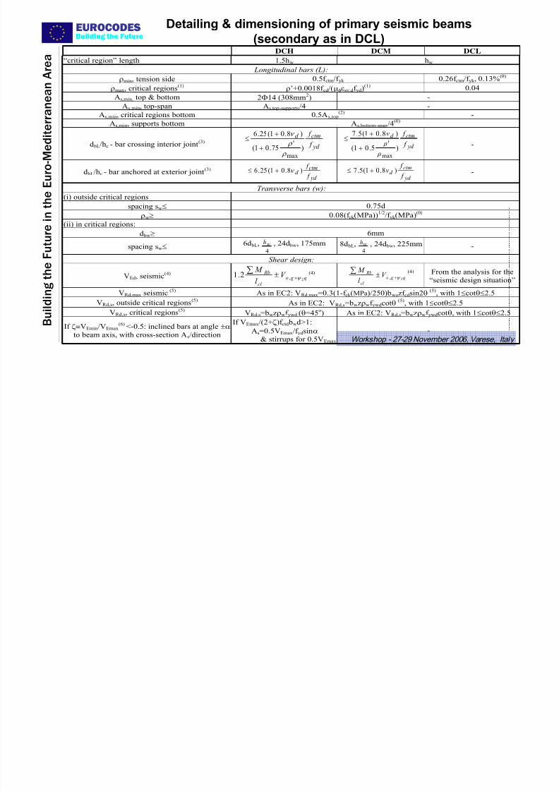
Detailing & dimensioning of primary seismic beams
(secondary as in DCL)
7/27/2019 Design of Buildings for Earthquake Resistance According to Eurocode 8 - Part 1
http://slidepdf.com/reader/full/design-of-buildings-for-earthquake-resistance-according-to-eurocode-8-part 44/53
B u i l d i n g t h e
F u t u r e i n t h
e E u r o - M e d i
t e r r a n e a n A r e a
g
Workshop - 27-29 November 2006, Varese, Italy
(secondary as in DCL) DCH DCM DCL
“critical region” length 1.5hw hw
Longitudinal bars (L): ρmin, tension side 0.5f ctm/f yk 0.26f ctm/f yk , 0.13%
(0)
ρmax, critical regions(1)
ρ’+0.0018f cd/(μφεsy,df yd)(1)
0.04
As,min, top & bottom 2Φ14 (308mm2) -
As,min, top-span As,top-supports/4 -
As,min, critical regions bottom 0.5As,top(2) -
As,min, supports bottom As,bottom-span/4(0)
d bL/hc - bar crossing interior joint(3)
yd ctmd
f f
)'
75.01()8.01(25.6
max ρ
ρ ν
++≤
yd ctmd
f f
ρ
ρν
)'
5.01()8.01(5.7
max
++≤
-
d bL/hc - bar anchored at exterior joint(3)
yd
ctmd
f
f )8.01(25.6 ν +≤
yd
ctmd
f
f ν )8.01(5.7 +≤
-
Transverse bars (w):
(i) outside critical regions
spacing sw≤ 0.75d
ρw≥ 0.08(f ck (MPa))1/2
/f yk (MPa)(0)
(ii) in critical regions:
d bw≥ 6mm
spacing sw≤ 6d bL,4
wh , 24d bw, 175mm 8d bL,4
wh , 24d bw, 225mm -
Shear design:
VEd, seismic(4)
q g o
cl
Rb V l
M 2,2.1 ψ +±∑ (4)
q g o
cl
Rb V l
M 2, ψ +±∑ (4)
From the analysis for the
“seismic design situation”
VRd,max seismic(5)
As in EC2: VRd,max=0.3(1-f ck (MPa)/250)bwozf cdsin2θ (5)
, with 1≤cotθ≤2.5
VRd,s, outside critical regions(5)
As in EC2: VRd,s=bwzρwf ywdcotθ (5)
, with 1≤cotθ≤2.5
VRd,s, critical regions(5) VRd,s=bwzρwf ywd (θ=45
o) As in EC2: VRd,s=bwzρwf ywdcotθ, with 1≤cotθ≤2.5
If ζ≡VEmin/VEmax(6) <-0.5: inclined bars at angle ±α
to beam axis, with cross-section As/direction
If VEmax/(2+ζ)f ctd bwd>1:
As=0.5VEmax/f ydsinα & stirrups for 0.5VEmax
-
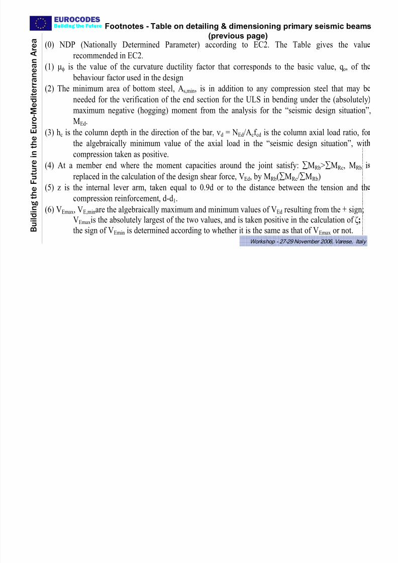
EUROCODESBuilding the Future Footnotes - Table on detailing & dimensioning primary seismic beams
7/27/2019 Design of Buildings for Earthquake Resistance According to Eurocode 8 - Part 1
http://slidepdf.com/reader/full/design-of-buildings-for-earthquake-resistance-according-to-eurocode-8-part 45/53
B u i l d i n g t h e
F u t u r e i n t h
e E u r o - M e d i
t e r r a n e a n A r e a
Workshop - 27-29 November 2006, Varese, Italy
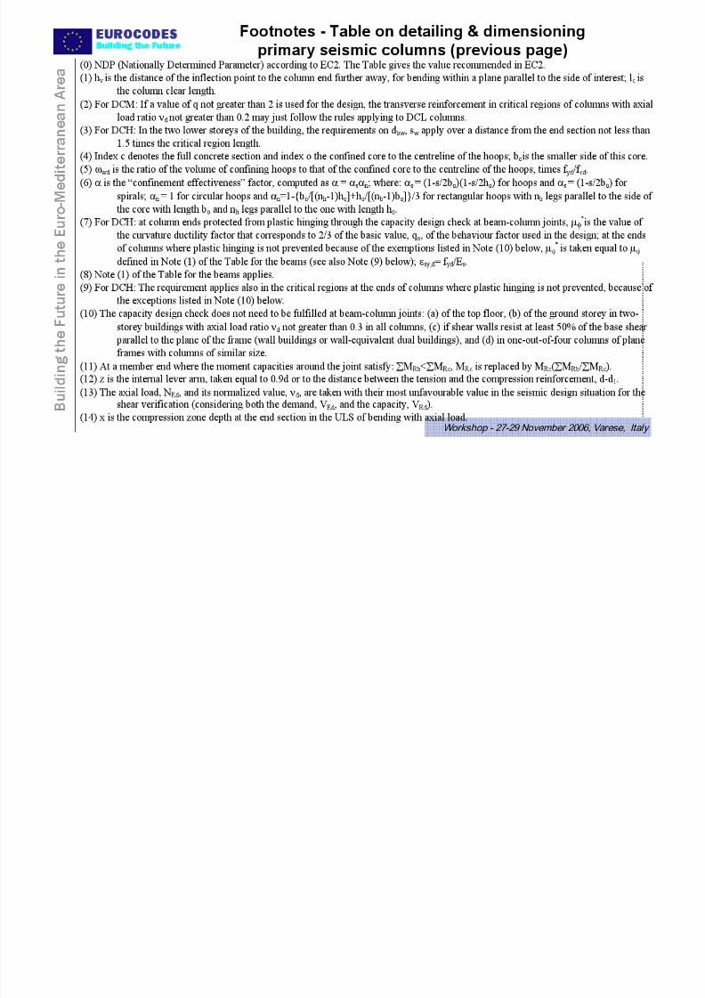
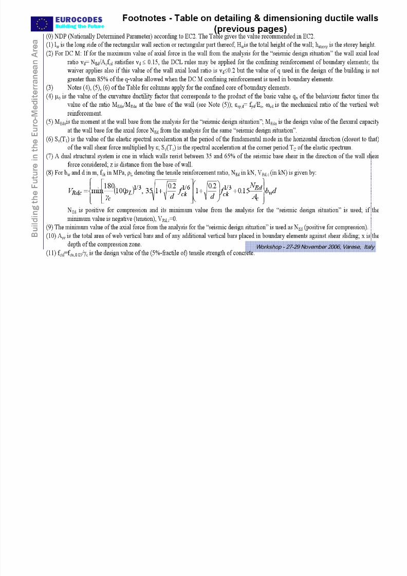
Footnotes Table on detailing & dimensioning primary seismic beams
(previous page)(0) NDP (Nationally Determined Parameter) according to EC2. The Table gives the valu
recommended in EC2.
(1) μφ is the value of the curvature ductility factor that corresponds to the basic value, qo, of th
behaviour factor used in the design
(2) The minimum area of bottom steel, As,min, is in addition to any compression steel that may b
needed for the verification of the end section for the ULS in bending under the (absolutelymaximum negative (hogging) moment from the analysis for the “seismic design situation”,
MEd.
(3) hc is the column depth in the direction of the bar, νd = NEd/Acf cd is the column axial load ratio, fo
the algebraically minimum value of the axial load in the “seismic design situation”, witcompression taken as positive.
(4) At a member end where the moment capacities around the joint satisfy: ∑MRb>∑MRc, MRb i
replaced in the calculation of the design shear force, VEd, by MRb(∑MRc/∑MRb)
(5) z is the internal lever arm, taken equal to 0.9d or to the distance between the tension and thcompression reinforcement, d-d1.
(6) VEmax, VE,minare the algebraically maximum and minimum values of VEd resulting from the ± sign;VEmaxis the absolutely largest of the two values, and is taken positive in the calculation of ζ;
the sign of VEmin is determined according to whether it is the same as that of VEmax or not.
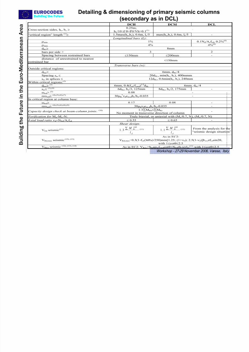
EUROCODESBuilding the Future
Detailing & dimensioning of primary seismic columns
(secondary as in DCL)
7/27/2019 Design of Buildings for Earthquake Resistance According to Eurocode 8 - Part 1
http://slidepdf.com/reader/full/design-of-buildings-for-earthquake-resistance-according-to-eurocode-8-part 46/53
B u i l d i n g t h e
F u t u r e i n t h
e E u r o - M e d i
t e r r a n e a n A r e a
Workshop - 27-29 November 2006, Varese, Italy
(secondary as in DCL)
DCH DCM DCL
Cross-section sides, hc, bc ≥ 0.25m;
hv/10 if θ=Pδ/Vh>0.1
(1) -
“critical region” length (1)≥ 1.5max(hc,bc), 0.6m, lc/5 max(hc,bc), 0.6m, lc/5 -
Longitudinal bars (L):
ρmin 1% 0.1Nd/Acf yd, 0.2%(0)
ρmax 4% 4%(0)
d bL≥ 8mm
bars per side ≥ 3 2
Spacing between restrained bars ≤150mm ≤200mm -
distance of unrestrained to nearest
restrained bar ≤150mm
Transverse bars (w):
Outside critical regions:
d bw≥ 6mm, d bL/4
Spacing sw ≤ 20d bL, min(hc, bc), 400mmm
sw in splices ≤ 12d bL, 0.6min(hc, bc), 240mm
Within critical regions:(2)
d bw≥ (3) 6mm, 0.4(f yd/f ywd)1/2d bL 6mm, d bL/4
sw≤
(3),(4)
6d bL, bo/3, 125mm 8d bL, bo/2, 175mm -ωwd≥ (5)
0.08 -
αωwd≥ (4),(5),(6),(7) 30μφ*νdεsy,d bc/bo-0.035 -
In critical region at column base:
ωwd≥ 0.12 0.08 -
αωwd≥ (4),(5),(6),(8),(9) 30μφνdεsy,d bc/bo-0.035 -
Capacity design check at beam-column joints: (10) 1.3∑MRb≤∑MRc
No moment in transverse direction of column-
Verification for Mx-My-N: Truly biaxial, or uniaxial with (Mz/0.7, N), (My/0.7, N)
xial load ratio νd=NEd/Acf cd ≤ 0.55 ≤ 0.65 -
Shear design:
VEd seismic(11)
cl
ends Rc
l
M ∑3.1 (11)
cl
ends Rc
l
M ∑1.1 (11)
From the analysis for the
“seismic design situation”
VRd,max seismic (12), (13)
As in EC2:
VRd,max=0.3(1-f ck (MPa)/250)min[1.25; (1+νd); 2.5(1-νd)]bwozf cdsin2θ,
with 1≤cotθ≤2.5
VRd,s seismic
(12), (13), (14)
As in EC2: VRd,s=bwzρwf ywdcotθ+NEd(h-x)/lcl
(13)
with 1≤cotθ≤2.5
7/27/2019 Design of Buildings for Earthquake Resistance According to Eurocode 8 - Part 1
http://slidepdf.com/reader/full/design-of-buildings-for-earthquake-resistance-according-to-eurocode-8-part 47/53
EUROCODESBuilding the Future
Detailing & dimensioning of ductile walls (cont’d next page)
DCH DCM DCL
7/27/2019 Design of Buildings for Earthquake Resistance According to Eurocode 8 - Part 1
http://slidepdf.com/reader/full/design-of-buildings-for-earthquake-resistance-according-to-eurocode-8-part 48/53
B u i l d i n g t h e
F u t u r e i n t h
e E u r o - M e d i t e r r a n e a n A r e a
Workshop - 27-29 November 2006, Varese, Italy
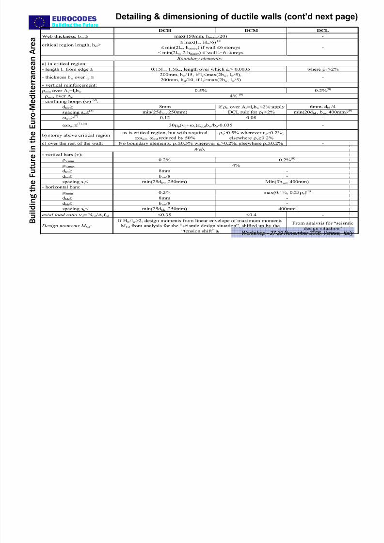
DCH DCM DCL
Web thickness, bwo≥ max(150mm, hstorey/20) -
critical region length, hcr ≥ ≥
max(lw, Hw/6)(1)
≤ min(2lw, h
storey) if wall ≤6 storeys
≤ min(2lw, 2 hstorey) if wall > 6 storeys
-
Boundary elements:
a) in critical region:
- length lc from edge ≥ 0.15lw, 1.5bw, length over which εc> 0.0035 where ρL>2%
- thickness bw over lc ≥ 200mm, hst/15, if lc≤max(2bw, lw/5),
200mm, hst/10, if lc>max(2bw, lw/5)-
- vertical reinforcement:
ρmin over Ac=lc bw 0.5% 0.2%(0)
ρmax over Ac 4% (0)
- confining hoops (w)(2)
:
d bw≥ 8mm 6mm, d bL/4
spacing sw≤(3) min(25d bh, 250mm)
if ρL over Ac=lc bw >2%:apply
DCL rule for ρL>2% min(20d bL, bwo 400mm)(0)
ωwd≥(2)
0.12 0.08 -
αωwd≥(3),(4)
30μφ(νd+ων)εsy,d bw/bo-0.035 -
b) storey above critical regionas is critical region, but with required
αωwd, ωwd reduced by 50%
ρv≥0.5% wherever εc>0.2%;
elsewhere ρv≥0.2%c) over the rest of the wall: No boundary elements. ρv≥0.5% wherever εc>0.2%; elsewhere ρv≥0.2% -
Web:
- vertical bars (v):
ρv,min 0.2% 0.2%(0)
ρv,max 4%
d bν≥ 8mm -
d bv≤ bwo/8 -
spacing sv≤ min(25d
bv, 250mm) Min(3b
wo, 400mm)
- horizontal bars:
ρhmin 0.2% max(0.1%, 0.25ρv)(0)
d bh≥ 8mm -
d bh≤ bwo/8 -
spacing sh≤ min(25d bh, 250mm) 400mm
axial load ratio νd= NEd/Acf cd ≤0.35 ≤0.4 -
Design moments M Ed :
If Hw/lw≥2, design moments from linear envelope of maximum moments
MEd from analysis for the “seismic design situation”, shifted up by the
“tension shift” al
From analysis for “seismic
design situation”
EUROCODESBuilding the Future
Detailing & dimensioning of ductile walls
(cont’d from previous page)
7/27/2019 Design of Buildings for Earthquake Resistance According to Eurocode 8 - Part 1
http://slidepdf.com/reader/full/design-of-buildings-for-earthquake-resistance-according-to-eurocode-8-part 49/53
B u i l d i n g t h e
F u t u r e i n t h
e E u r o - M e d i t e r r a n e a n A r e a
Workshop - 27-29 November 2006, Varese, Italy
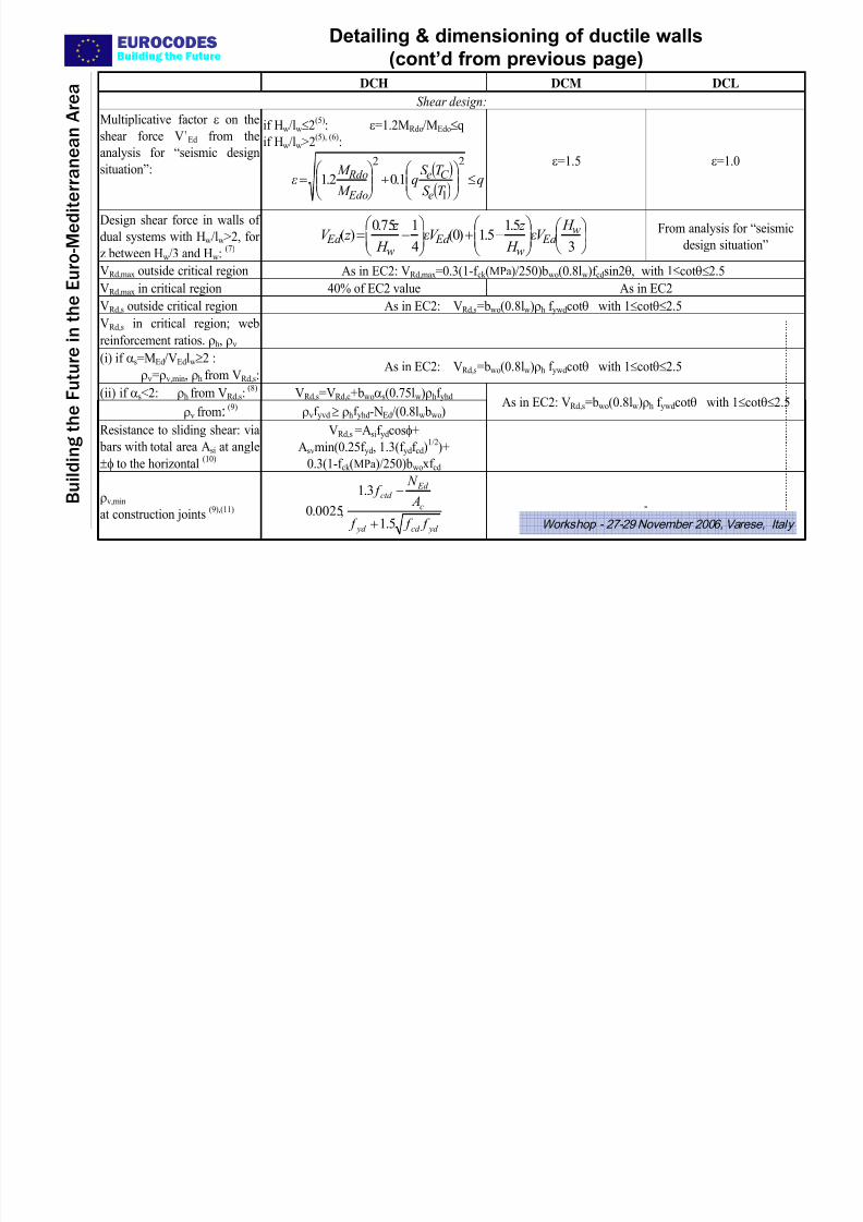
( p p g ) DCH DCM DCL
Shear design:
Multiplicative factor ε on the
shear force V’Ed from the
analysis for “seismic design
situation”:
if Hw/lw≤2(5)
: ε=1.2MRdo/MEdo≤q
if Hw/lw>2(5), (6)
:
( )( )
qT S
T S q
M
M ε
e
C e
Edo
Rdo ≤⎟⎟ ⎠
⎞⎜⎜⎝
⎛ +⎟⎟
⎠
⎞⎜⎜⎝
⎛ =
2
1
2
1.02.1 ε=1.5 ε=1.0
Design shear force in walls of
dual systems with Hw/lw>2, for
z between Hw/3 and Hw:(7)
⎟ ⎠
⎞⎜⎝
⎛ ⎟⎟ ⎠
⎞⎜⎜⎝
⎛ −+⎟⎟
⎠
⎞⎜⎜⎝
⎛ −=
3
5.15.1)0(
4
175.0)( w
Ed w
Ed w
Ed H
V ε H
z V ε
H
z z V From analysis for “seismic
design situation”
VRd,max outside critical region As in EC2: VRd,max=0.3(1-f ck (MPa)/250)bwo(0.8lw)f cdsin2θ, with 1≤cotθ≤2.5
VRd,max in critical region 40% of EC2 value As in EC2
VRd,s
outside critical region As in EC2: VRd,s
=bwo
(0.8lw)ρ
hf ywd
cotθ with 1≤cotθ≤2.5
VRd,s in critical region; web
reinforcement ratios. ρh, ρν
(i) if αs=MEd/VEdlw≥2 :
ρν=ρv,min, ρh from VRd,s:As in EC2: VRd,s=bwo(0.8lw)ρh f ywdcotθ with 1≤cotθ≤2.5
(ii) if αs<2: ρh from VRd,s:(8)
VRd,s=VRd,c+bwoαs(0.75lw)ρhf yhd
ρv from:(9)
ρνf yvd≥ ρhf yhd-NEd/(0.8lw bwo)
As in EC2: VRd,s=bwo(0.8lw)ρh f ywdcotθ with 1≤cotθ≤2.5
Resistance to sliding shear: via
bars with total area Asi at angle
±φ to the horizontal(10)
VRd,s =Asif ydcosφ+
Asvmin(0.25f yd, 1.3(f ydf cd)1/2
)+
0.3(1-f ck (MPa)/250)bwoxf cd
ρv,min
at construction joints(9),(11)
yd cd yd
c
Ed ctd
f f f
A
N f
5.1
3.1
,0025.0 +
−
-
7/27/2019 Design of Buildings for Earthquake Resistance According to Eurocode 8 - Part 1
http://slidepdf.com/reader/full/design-of-buildings-for-earthquake-resistance-according-to-eurocode-8-part 50/53
EUROCODESBuilding the Future

7/27/2019 Design of Buildings for Earthquake Resistance According to Eurocode 8 - Part 1
http://slidepdf.com/reader/full/design-of-buildings-for-earthquake-resistance-according-to-eurocode-8-part 51/53
B u i l d i n g t h e
F u t u r e i n t h
e E u r o - M e d i t e r r a n e a n A r e a
Workshop - 27-29 November 2006, Varese, Italy
STRUCTURE OF EN1998-1:20041 General
2 Performance Requirements and Compliance Criteria
3 Ground Conditions and Seismic Action
4 Design of Buildings
5 Specific Rules for Concrete Buildings
6 Specific Rules for Steel Buildings
7 Specific Rules for Steel-Concrete Composite Buildings
8 Specific Rules for Timber Buildings
9 Specific Rules for Masonry Buildings10 Base Isolation
EUROCODESBuilding the Future
7/27/2019 Design of Buildings for Earthquake Resistance According to Eurocode 8 - Part 1
http://slidepdf.com/reader/full/design-of-buildings-for-earthquake-resistance-according-to-eurocode-8-part 52/53
B u i l d i n g t h e
F u t u r e i n t h
e E u r o - M e d i t e r r a n e a n A r e a
Workshop - 27-29 November 2006, Varese, Italy
MASONRY BUILDINGSMainly for regions of rather low-seismicity.
Nationally Determined Parameters (NDPs) for national flexibility:
• Allowable type of masonry units & of perpend joints
• Min. strength of masonry units & mortar;• Max. PGA for use of unreinforced masonry w/ EC6 alone, or w/ EC8;
• q-factor values for all types of masonry buildings (ranges given, instead of single values) other than those per EC6 alone;
• Geometric limitations for shear walls:
– min. thickness;
– max. slenderness (height-to-thickness);
– max height of openings relative to wall length;
• Conditions for design w/o detailed calculations (rules for “simple masonrybuildings”):
– Max. no. of storeys & min. horizontal area of walls, as function of PGA;
– Max. aspect ratio in plan & deviation of plan from rectangular envelope;
– Max. difference of mass & wall X-section between adjacent storeys.
EUROCODESBuilding the Future

7/27/2019 Design of Buildings for Earthquake Resistance According to Eurocode 8 - Part 1
http://slidepdf.com/reader/full/design-of-buildings-for-earthquake-resistance-according-to-eurocode-8-part 53/53
B u i l d i n g t h e F u t u r e i n t h
e E u r o - M e d i t e r r a n e a n A r e a
Workshop - 27-29 November 2006, Varese, Italy
MASONRY BUILDINGS (cont’d)
Types of masonry for EQ-resistance:
• Unreinforced masonry per EC6 alone (not recommended for PGA at site
> 0.1g): q=1.5
• Unreinforced masonry, w/ horizontal RC belts (As>200mm2) at <4m centres(not recommended for PGA at site > 0.15g):
q (NDP) = 1.5 - 2.5 (recommended: q=1.5)
• Confined masonry, w/ horizontal RC belts > 0.15x0.15 m (As>300mm2 or 1%) at <4 m centres and similar vertical ones at <5 m centres & at wallintersections & edges of large openings:
q (NDP) = 2 - 3 (recommended: q=2).
• Reinforced masonry, w/ ρh> 0.05% & ρv> 0.08% (plus vertical steel w/ As>200mm2 at <5m centres & at wall intersections or free edges):
q (NDP) =2.5 - 3 (recommended: q=2.5).
Related Documents