International Journal of Advanced Robotic Systems, www.intechweb.org Vol. 8, No. 1 (2011) ISSN 1729-8806, pp 131-139 www.intechopen.com Design of Autonomous Underwater Vehicle Tadahiro Hyakudome Japan Agency for Marine-Earth Science and Technology (JAMSTEC), Japan Abstract There are concerns about the impact that global warming will have on our environment, and which will inevitably result in expanding deserts and rising water levels. While a lot of underwater vehicles are utilized, AUVs (Autonomous Underwater Vehicle) were considered and chosen, as the most suitable tool for conduction survey concerning these global environmental problems. AUVs can comprehensive survey because the vehicle does not have to be connected to the support vessel by tether cable. When such underwater vehicles are made, it is necessary to consider about the following things. 1) Seawater and Water Pressure Environment, 2) Sink, 3) There are no Gas or Battery Charge Stations, 4) Global Positioning System cannot use, 5) Radio waves cannot use. In the paper, outline of above and how deal about it are explained. 1. Introduction The ocean occupied approximately 71% of surface of the earth still have a lot of unknown parts. Therefore various studies and development about the ocean such as marine environment, submarine earthquake, ocean life, marine resources research and so on are carried out. The collection of ocean data by survey and observation in the actual sea is indispensable for the studies and the development. Because the ocean has low transparency and cannot observe the whole deep sea in detail from the surface, so, survey and observation with the ship is not enough. However the water pressure cannot step into the deep sea easily because 1 atmospheric pressure is increasing every 10m diving. Various underwater apparatuses such as manned submersible, unmanned underwater vehicle and so on are developed as tools to survey and observation the deep sea since the Bathyscape invented by Prof. Auguste Piccard was launched in 1948. The manned submersibles such as “ALVIN”, “NAUTILE”, “MIRS” and “SHINKAI6500” are good at the visual observation and sampling in small range. The towed vehicles are good at wide area survey. The Remotely Operated Vehicles (ROVs) are good at detailed observation and sampling in small range. The Autonomous Underwater Vehicles (AUVs) such as “Autosub”, “Hugin”, “Thesus” and “URASHIMA” and so on are good at wide area detailed survey because the vehicles does not have to be connected to the support vessel by tether cable and can close to seafloor. The development of AUVs is enabled with recent advanced computing and other various advanced technologies shown in figure 1. Figure 1. The Elemental Technologies for Autonomous Underwater Vehicle

Welcome message from author
This document is posted to help you gain knowledge. Please leave a comment to let me know what you think about it! Share it to your friends and learn new things together.
Transcript
International Journal of Advanced Robotic Systems, www.intechweb.org Vol. 8, No. 1 (2011) ISSN 1729-8806, pp 131-139 www.intechopen.com
Design of Autonomous Underwater Vehicle
Tadahiro Hyakudome Japan Agency for Marine-Earth Science and Technology (JAMSTEC), Japan
Abstract There are concerns about the impact that global
warming will have on our environment, and which will
inevitably result in expanding deserts and rising water
levels. While a lot of underwater vehicles are utilized,
AUVs (Autonomous Underwater Vehicle) were considered
and chosen, as the most suitable tool for conduction survey
concerning these global environmental problems. AUVs
can comprehensive survey because the vehicle does not
have to be connected to the support vessel by tether cable.
When such underwater vehicles are made, it is necessary to
consider about the following things. 1) Seawater and Water
Pressure Environment, 2) Sink, 3) There are no Gas or
Battery Charge Stations, 4) Global Positioning System
cannot use, 5) Radio waves cannot use. In the paper, outline
of above and how deal about it are explained.
1. Introduction
The ocean occupied approximately 71% of surface of the
earth still have a lot of unknown parts. Therefore various
studies and development about the ocean such as marine
environment, submarine earthquake, ocean life, marine
resources research and so on are carried out. The
collection of ocean data by survey and observation in the
actual sea is indispensable for the studies and the
development. Because the ocean has low transparency
and cannot observe the whole deep sea in detail from the
surface, so, survey and observation with the ship is not
enough. However the water pressure cannot step into the
deep sea easily because 1 atmospheric pressure is
increasing every 10m diving.
Various underwater apparatuses such as manned
submersible, unmanned underwater vehicle and so on are
developed as tools to survey and observation the deep sea
since the Bathyscape invented by Prof. Auguste Piccard
was launched in 1948. The manned submersibles such as
“ALVIN”, “NAUTILE”, “MIRS” and “SHINKAI6500” are
good at the visual observation and sampling in small range.
The towed vehicles are good at wide area survey. The
Remotely Operated Vehicles (ROVs) are good at detailed
observation and sampling in small range. The Autonomous
Underwater Vehicles (AUVs) such as “Autosub”, “Hugin”,
“Thesus” and “URASHIMA” and so on are good at wide
area detailed survey because the vehicles does not have to
be connected to the support vessel by tether cable and can
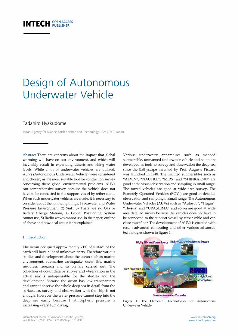
close to seafloor. The development of AUVs is enabled with
recent advanced computing and other various advanced
technologies shown in figure 1.
Figure 1. The Elemental Technologies for Autonomous
Underwater Vehicle
132 International Journal of Advanced Robotic Systems, Vol. 8, No. 1 (2011)
It is necessary to consider about following things on
developing Autonomous Underwater Vehicle: 1)
Seawater and Water Pressure Environment, 2) Sink, 3)
There is No Gas or Battery Charge Stations, 4) Global
Positioning System Cannot Use, 5) Radio Waves Cannot
Use and 6) Autonomous.
2. Sea Water and Water Pressure Environment
The ocean is the environment that, as you know, filled
with seawater. Because viscosity of seawater is high, the
ocean is hard to move in comparison with the atmosphere.
And the remarkable characteristic of the ocean is the
environment where 1 atmospheric pressure increases by
every 10 meters diving. Therefore, the water pressure
grows big so as to go into the deep sea and will increase
strong external force as things are destroyed.
All of underwater vehicles are controlled by electronics.
However, the elements of most of electronics are not
exposed to seawater to short‐circuit. In addition there are
the elements of electronics broken by high water pressure.
Therefore, solid pressure vessels are necessary to use the
electronics in underwater. The pressure vessels are
required to be enough strong for water pressure in the
working depth, lightweight, not corroded and so on. A
cylindrical shape or a ball type is most suitable for the
shape of the pressure vessel. The water pressure increases
according to depth, and so the hull of pressure vessel
needs to increase thickness to add to strength depending
on depth. However the strong pressure vessels become
very heavy weight. It is not good with an aspect of energy
efficiency for a deep and long cruising range underwater
vehicle so that the pressure vessels hold a big part of the
weight of the body. Therefore light and strong structure
material for pressure vessel is important.
Generally, Aluminum alloy, Titanium alloy and High
Tensile Strength Steel are used as a material of pressure
vessel in JAMSTEC. The aluminum alloy is light weight,
high strength, reasonable value, but surface treatment is
necessary to use it in the sea. The aluminum alloy has the
following characteristic: the specific gravity is 2.7, good
workability, not become magnetized, resists low
temperature, easy to weld and so on. Because navigation
systems are not influenced, it is good that the aluminum
alloy does not become magnetized. It is important that
heat conductivity of the aluminum alloy is good because
of heat radiation of the electronics in the pressure vessel.
The aluminum alloy has various kinds from 1000 series to
8000 series. 5000, 6000 or 7000 series of the aluminum
alloy is mainly used in JAMSTEC. As for 5000 series
aluminum alloy, the strength is ordinary, but corrosion
resistance is high. As for 7000 series aluminum alloy, the
strength is high, but corrosion resistance is ordinary. The
performance of the aluminum alloy of 6000 series is the
middle of 5000 series and 7000series. Corrosion measures
are necessary to use the aluminum alloy in the sea.
Effective means to resist seawater and corrosion is surface
treatment. The surface treatments of the aluminum alloy
are anodizing, TUFRAMR, electrolysis nickel plating,
electroless nickel plating, painting. The TUFRAMR is a
technique to make surface enhancement coating of
General Magnaplate.
The titanium alloy is light weight, high strength,
maintenance free, but expensive. The titanium alloy has
the following characteristic: the specific gravity is 4.5, high
corrosion resistance, low electric conductivity, low heat
conductance, not becomes magnetized, low workability.
Particularly, the specific strength of the Ti‐6Al‐4V alloy is
the strongest level. The titanium alloy does not need the
surface treatment even if used in the sea.
The high tensile strength steel is high strength, moderate
value, but heavy weight and surface treatment is
necessary to use it in the sea. The specific gravity of the
high tensile strength steel is about 7.9. The high tensile
strength steel has more than 490Mpa tensile strength.
The pressure vessel is designed with materials mentioned
above. The parameter that is necessary for the pressure
vessel design is buckling stress and yield stress, and yield
stress becomes dominant in the high pressure environment
of the deep sea. The specifications of the pressure vessel
design are the maximum working depth, the pressure
vessel inside diameter and length, safety factors. And it is
necessary to be considered about corrosion and electrolytic
corrosion. The metal corrosion in the seawater goes based
on the electrochemic reaction. The materials are made
surface treatment to protect against the corrosion so that
they do not touch the seawater directly. The electrolytic
corrosion is a corrosion phenomenon to occur when two
kinds of different metal comes into contact in seawater. The
high metals of the ionization tendency melt in seawater,
and the metals melting become quicker in the corrosion
speed than case alone. As protecting against the electrolytic
corrosion, some insulator such as resin or rubber is attached
to metal contact surface, or sacrifice electrodes are attached
to metal.
The development of the new type pressure vessel by
different materials is carried out to reduce the weight of
the underwater vehicles in JAMSTEC. One of the
materials is magnesium alloy, and the other is Super
Carbon Fiber. In late years, many magnesium alloys are
developed as the parts of cars, aircraft and mobile devices.
The specific gravity of the magnesium alloy is 1.8 that is
about 1/3 of the titanium or about 2/3 of aluminum. The
magnesium alloy is the most lightweight in metal
structure materials, and the specific strength is strongest.
The pressure vessel made by magnesium alloy shown in
figure 2 was produced experimentally, and strength of it
was evaluated. The size of it is 90mm inside diameter,
130mm length and 9mm thickness. The pressurization test
for it was performed with hyperbaric chamber. At the
pressurization test, the shrinkage of the pressure vessel
was measured by strain gages. The water pressure was

Tadahiro Hyakudome: Design of Autonomous Underwater Vehicle 133
pressurized in 2MPa per minute to 40Mega Pascal,
maintained 20 minutes at 40MPa and deceased pressure
in 2MPa per minute. The relations of water pressure and
strain of tube part of the pressure vessel are shown in
figure 3. As a result of pressurization test, it was
confirmed that the pressure vessel made by magnesium
alloy was not broken by water pressure more than 40Mpa.
There is the possibility that the magnesium alloy
contributes to the lightweighting of the vehicle. However,
there are a lot of problems that must be settled to use the
magnesium alloy in underwater. The most important
problem is corrosion by seawater and electrochemic
corrosion.
The Super Carbon Fiber (SCF) is Carbon fiber Reinforced
Plastic (CFRP) rod having high moment of bending and
high pulling strength developed in Kyushu University. A
pressure vessel made by aluminum alloy is reinforced with
SCF. Consumption of aluminum decreases by this method
and can reduce the weight of the pressure vessel. A hull
thickness of the aluminum and a diameter of the SCF were
calculated by finite element analysis, and a pressure vessel
is designed. The hybrid pressure vessel type 1 is shown in
figure 4. The size of it is 100mm inside diameter, 150mm
length and 4mm thickness. The performance of the
prototype pressure vessel was evaluated in a pressurization
test with hyperbaric chamber. At the pressurization test,
the shrinkage of the pressure vessel was measured by strain
gages. The water pressure was pressurized in 3MPa per
minute. The time series of water pressure and strain of tube
part of the pressure vessel are shown in figure 5. At the
result of pressurization test, the hybrid pressure vessel type
1 was broken at 58.74Mpa. Here, a pressure vessel made by
aluminum alloy of the thickness of 4mm is broken in
10Mpa by the calculated result. It was confirmed that
reinforcement with the SCF was effective. The second unit
was designed again. And the hybrid pressure vessel type 2
was produced experimentally. The strength of it is going to
be evaluated in near future. The hybrid pressure vessel is
still the way of the development, and various problems are
left.
Figure 2. The Prototype Pressure Vessel made by Mg Alloy (Tube
Part)
Figure 3. The Relation of Water Pressure v.s. Strain
Figure 4. The Prototype Hybrid Pressure Vessel Type 1
Figure 5. The Time Series of the Strain of the Hybrid Pressure
Vessel
3. Sink ‐ Fat to Underwater Vehicles ?
The deep underwater vehicles became heavy weight even
if use lightweight materials for frames and pressure
vessels. Some materials need to be able to float a heavy
body to use a deep underwater vehicle like a space shuttle
many times. Therefore it is necessary to add buoyancy
materials such as the human fat to a deep underwater
vehicle.
The buoyancy materials include gasoline, wood,
expandable polystyrene and syntactic foam. The
characteristic of the gasoline is lighter than seawater and
not broken by water pressure because of liquid. Its specific
gravity is around 0.8 from 0.75. However, it is
large‐capacity need to use it as the buoyancy material.
And it is flammable. The volume of gasoline changes by
water pressure and temperature. Therefore, the handling

134 International Journal of Advanced Robotic Systems, Vol. 8, No. 1 (2011)
of gasoline is difficult. The characteristic of the wood is
light weight, cheapness, good processing. However, it is
destroyed by the water pressure, and weight increases
including water. Therefore, the wood is not suitable as a
buoyancy material for the deep sea. The expandable
polystyrene is super light. However, it is compressed by
water pressure and loses buoyancy. Therefore, the
expandable polystyrene is not suitable as a material for
the deep sea.
The syntactic foam consists of grass micro balloons and
epoxy resin. It has high compressive strength against
water pressure. Its specific gravity is around 0.65 from 0.3,
and it is chosen depending on maximum working depth
of the vehicles. This buoyancy material is machined in
various forms with a saw or a drill. And it is filled
clearances of pressure vessels of the body like human fat.
4. There is No Gas or Battery Charge Station
The underwater power source is one of very important
elements to operate underwater vehicle particularly AUV
for a long time. Because there is no energy supply places
in underwater. Many research and development about the
underwater power source are performed. When the
research and development of the power source, following
things need to be considered: small and light weight, put
in a pressure vessel or resist against water pressure, work
against low water temperature, vibration, noise, reliability
and for maintenance. The power source has heaviest
weight with the components of the vehicle. When the
power source becomes big in proportion to the scale up of
the body, maneuverability and energy efficiency worsen.
Therefore it is important that the power source is small
and light weight. Low vibration and low noise
environment is important not to interfere acoustic
equipments such as observation devices or
communications devices. 1) Primary Batteries, 2)
Secondary Batteries, 3) Internal Combustion Engines, 4)
External Combustion Engines, 5) Radioisotope Batteries,
6) Small Nuclear Reactors and 7) Fuel Cells are considered
as underwater power source. 1) The primary battery has
simple structure consisting of an anode, a cathode and
electrolyte. It can expose to water pressure. It is small and
light weight. It has high energy density. It can be used
once. The use of the primary battery takes running cost. It
is used as a power supply for independent devices such as
transponders. 2) The secondary battery also has simple
structure consist of an anode, a cathode and electrolyte. It
also can expose to water pressure. It can be used
repeatedly. Running cost is low. It has high reliability. The
secondary battery must not be overcharged or
overdischarged. The secondary battery for underwater
vehicles includes lead batteries, silver zinc batteries and
lithium‐ion batteries. The secondary battery is easy to be
treated and most suitable as a battery for the deep
underwater vehicle. 3) The close cycle diesel engine is the
only internal combustion engine in the practical use as
underwater power source. It is robust for environmental
change. It is a reasonable system. It must be put in a
pressure vessel. Protections against vibration and noise
are required to use it as underwater power source. 4) The
external combustion engine is the system which converts
thermal energy into kinetic energy. The stirling engine is a
kind of the external combustion engine. The conversion
efficiency from thermal energy to kinetic energy of the
stirling engine is high. It has small vibration and noise. It
can work without depending on the kind of heat source. It
cannot response to sudden changes. It must be put in a
pressure vessel. 5) The radioisotope converts the energy
that occurred by the nuclear decay of the radioactive
element into electricity by a thermoelectric transducer. AS
for the radioisotope, long‐term power supply is possible.
It works calmly. It is maintenance free. It must be put in a
pressure vessel. 6) As for the small nuclear reactor,
long‐term power supply is possible. It is suitable for
underwater power source. However, it is difficult to
handle. 7) The fuel cell is a kind of electric generator using
the chemical reaction of hydrogen combines with
hydrogen. It is able to generate electricity directly from
chemical reaction without any combustion or
intermediate steps. There are various kinds of fuel cell,
but the solid Polymer Electrolyte Fuel Cell (PEFC) system
is most suitable for underwater power sources. The
research and development of the Lithium‐ion Secondary
Battery and Fuel Cell are carried out in JAMSTEC.
At first, it is the lithium‐ion secondary battery. Electric
Power storage is an important technology for all
equipment of the underwater vehicle because
environmental pressure is high, the temperature is 5
degrees Celsius or less, and conditions are unsuitable for
many chemical reactions in the deep sea. Battery capacity
is mainly dependent on its mass; this means that the
cruising range is proportional to the mass of the battery.
To solve this problem, a high energy density battery and
its enclosures are being developed. Concretely, batteries
are enclosed with oil, to equate environmental pressure
and to be insulated in seawater. This is called the oil
compensated method, and is applied to various batteries.
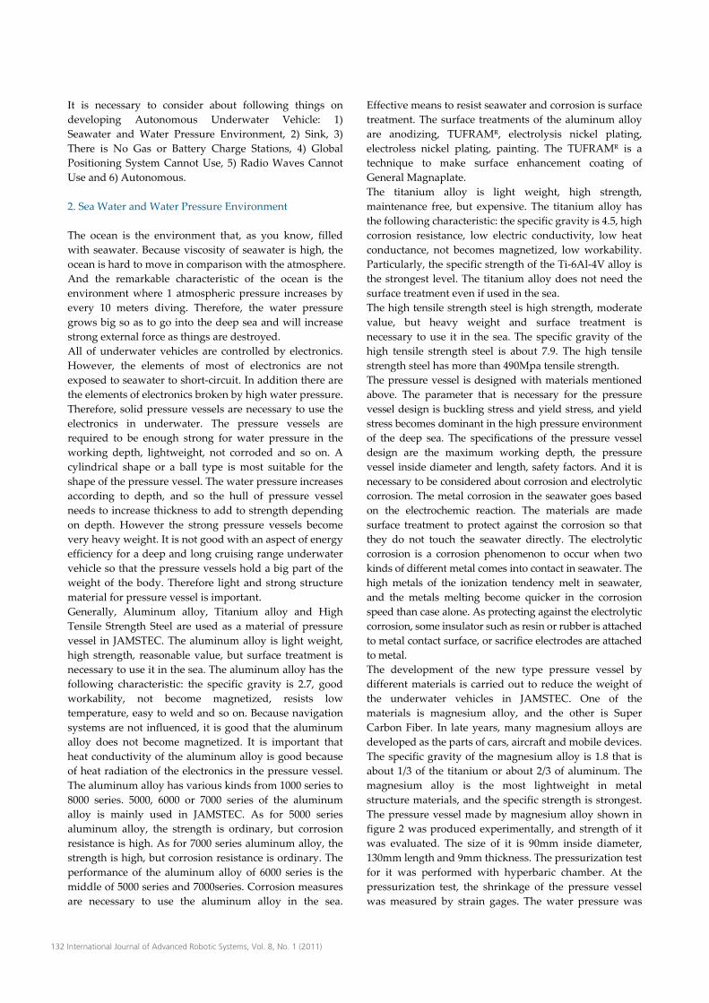
Secondary batteries that have been put to practical use in
the sea are shown in Figure 6. Typical cells are lead‐acid,
nickel‐cadmium, silver‐zinc and lithium‐ion. The vertical
and horizontal axes in the figure indicate the energy
density in weight and volume respectively. The
Lithium‐ion battery has many merits more than other
batteries as follows: 1) Energy density is very high, this is
the most important factor when choosing a battery, 2)
operating voltage is also high, 3) no need to revitalize
according to its memory, 4) safety, 5) maintenance free, 6)
emits no gas when charging 7) longer life‐time than the
other batteries. The one of actual use Lithium‐ion battery
is shown in Figure 7. The oil‐filled 300Ah Lithium‐Ion
battery for the vehicle was developed in 2000. The battery
Tadahiro Hyakudome: Design of Autonomous Underwater Vehicle 135
has three groups in parallel. One group has 120V and
100Ah. The energy density of the battery is 150Wh/kg. The
more high energy density Lithium‐ion battery is under
development now.
Next, it is the Closed Cycle Fuel Cell system. Usually, many
underwater vehicles used rechargeable battery such that
the lithium‐ion battery or the silver‐zinc battery for a power
source. However the case of long term working type
untethered underwater vehicle, it needs many electric
power supplies in proportion to operation time. To extend
operating time, the battery must become heavier and lager.
But it makes worse the maneuverability and energy
efficiency of the vehicle. So the development of the fuel cell
for underwater power sources is planned. The fuel cell is a
kind of electric generator using the chemical reaction of
hydrogen and oxygen. It is able to generate electricity
directly from chemical reaction without any combustion or
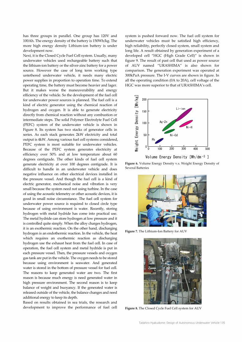
intermediate steps. The solid Polymer Electrolyte Fuel Cell
(PEFC) system of the underwater vehicle is shown in
Figure 8. Its system has two stacks of generator cells in
series. As each stack generates 2kW electricity and total
output is 4kW. Among various fuel cell systems considered,
PEFC system is most suitable for underwater vehicles.
Because of the PEFC system generates electricity at
efficiency over 50% and at low temperature about 60
degrees centigrade. The other kinds of fuel cell system
generate electricity at over 100 degrees centigrade. It is
difficult to handle in an underwater vehicle and does
negative influence on other electrical devices installed in
the pressure vessel. And though the fuel cell is a kind of
electric generator, mechanical noise and vibration is very
small because the system need not using turbine. In the case
of using the acoustic telemetry or other acoustic devices, it is
good in small noise circumstance. The fuel cell system for
underwater power source is required to closed circle type
because of using environment is water. Recently, storing
hydrogen with metal hydride has come into practical use.
The metal hydride can store hydrogen at low pressure and it
is controlled quite simply. When the alloy charges hydrogen,
it is an exothermic reaction. On the other hand, discharging
hydrogen is an endothermic reaction. In the vehicle, the heat
which requires an exothermic reaction as discharging
hydrogen use the exhaust heat from the fuel cell. In case of
operation, the fuel cell system and metal hydride is put in
each pressure vessel. Then, the pressure vessels and oxygen
gas tank are put in the vehicle. The oxygen needs to be stored
because using environment is seawater. And generated
water is stored in the bottom of pressure vessel for fuel cell.
The reasons to keep generated water are two. The first
reason is because much energy is need generated water in
high pressure environment. The second reason is to keep
balance of weight and buoyancy. If the generated water is
released outside of the vehicle, the balance changes and need
additional energy to keep its depth.
Based on results obtained in sea trials, the research and
development to improve the performance of fuel cell
system is pushed forward now. The fuel cell system for
underwater vehicles must be satisfied high efficiency,
high reliability, perfectly closed system, small system and
long life. A result obtained by generation experiment of a
developed cell “HGC (High Grade Cell)” is shown in
figure 9. The result of past cell that used as power source
of AUV named “URASHIMA” is also shown for
comparison. The generation experiment was operated at
300kPaA pressure. The I‐V curves are shown in figure. In
all the operating condition (0A to 20A), cell voltage of the
HGC was more superior to that of URASHIMA’s cell.
Figure 6. Volume Energy Density v.s. Weight Energy Density of
Several Batteries
Figure 7. The Lithium‐Ion Battery for AUV
Figure 8. The Closed Cycle Fuel Cell system for AUV

136 International Journal of Advanced Robotic Systems, Vol. 8, No. 1 (2011)
Figure 9. The I‐V curves of the HGC and URASHIMA’s cell
5. Where is The Vehicle Now?
The positional information of the vehicle is indispensable
to obtain the marine data with the meaning. However, the
positional information with the Global Positioning System
is not available because radio waves are not usable in
underwater. The vehicle itself calculates its position using
Inertial Navigation System (INS) and velocity log, or the
vehicle is informed its position by a support vessel or a
transponder with acoustic navigation system. One of
Inertial Navigation Systems is shown in figure 10. The INS
calculates absolute position of the moving body in real
time. The Type of the INS applied in JAMSTEC is the
strap‐down. The strap‐down method is fellow method
that inertia sensors are fixed to the moving body, the
sensor output is counted backward, and the rate of change
is estimated. The INS developing in JAMSTEC is
composed of a sensor unit and an arithmetical unit. The
senor unit is composed of three gyroscopes and three
accelerometers. The gyroscope is a measure detecting an
angle and an angular velocity of an object. It has five kinds
of methods that are rate gyros, vibrating structure gyros,
gas rate gyros, fiber optic gyros and ring laser gyros. The
rate gyro uses a spinning top. The vibrating structure gyro
uses the resonance such as tuning forks. As for the gas rate
gyro, gas is sprayed on the heat rays in a housing. Heat
rays temperature detects that spray is curved by Coriolis
force when the housing turns around. As for the fiber
optic gyro and ring laser gyro, laser beams is made to go
around by mirrors or in a fiber in the housing. The
phenomenon that timings from the emission to receiving
of the laser changed when the housing turns around is
used. Among five kinds of gyros, the ring laser gyro is one
of optical rate gyro that has high precision and a wide
dynamic range. The arithmetical unit defines the
three‐dimensional coordinate system inside it (INS
coordinate system), and an accelerometer and a gyro are
set on each axis of it. The outputs of the accelerometers are
processed by the coordinate transform matrix which is
constructed by the output from the gyros. These are
integrated twice. Consequently, the current absolute
position of the moving body is calculated. The current
posture of it is calculated by the coordinate transform
matrix. The coordinate transform matrix expresses the
posture relationship between the INS coordinate system
and the Earth coordinate system. The several algorithms
to reduce calculations error of the INS is developing in
JAMSTEC.
The vehicle is capable of cruising dozens of times owing
to the internal power supply systems. However it is very
difficult for it to cruise with high precision for a long time
autonomously, dependent only on the INS, because the
position data calculated from INS includes an error factor,
and the error increases with the passage of time. Therefore
the vehicle has a hybrid system which combines the INS
and the velocity log. This hybrid system enables the
vehicle to get more accurate position data than using only
the INS. The velocity in underwater is measured by
following four measures, Pitot tube velocity log, rotor
type velocity logs, electromagnetic velocity logs, Doppler
Velocity Logs (DVLs). The Pitot tube velocity log has good
accuracy in middle range speed measurement. It is
influenced by turbulence and bubble, and precision
deteriorates. In addition, it is affected by temperature and
density of the seawater. It has some errors when the
vehicle turns. Anything should not attach to its sensor
part. So, the pitot tube velocity log is not suitable for the
underwater velocity log. The rotor type velocity log is
good in the measurement of the low speed range. It is
affected by turbulence. The influence of temperature and
the density of the seawater on it is small. Its measurement
accuracy is low. So, the rotor type velocity log is not
suitable for the cruising type underwater vehicles. The
electromagnetic velocity log has effective ranges from
slight low speed to high speed. It is highly precise. It is
affected by turbulence. It is not influenced by temperature
and density of the seawater. It has some errors when the
vehicle turns. So, the electromagnetic velocity log is not
suitable for the cruising type underwater vehicles. The
Doppler velocity log has effective ranges from low speed
to high speed. It has small influence of the turbulence and
small error when the vehicle turns. Also, it can measure
against water or seafloor alternatively and correct
influence of temperature and the density of the seawater.
The Doppler Velocity Log is suitable for the cruising type
underwater vehicle.
Figure 10. The Inertial Navigation System
Accelerometer
Ring Laser Gyro
Inertial
Nvaigation
System

Tadahiro Hyakudome: Design of Autonomous Underwater Vehicle 137
6. Radio Waves Cannot Use
Radio wave is a not usable in the sea. However, it is
necessary for the vehicle to communicate with the support
vessel. The acoustic telemetry is the only effective method
in the underwater communication method. So, the vehicle
communicates with the support vessel by acoustic
telemetry. There are analog communication and digital
communication for acoustic telemetry. It is digital
communication to have the communication of various
data. The underwater acoustic communication methods
are Frequency Shift Keying (FSK), Phase Shift Keying
(PSK), Quadrature Amplitude Modulation (QAM). The
FSK can transmit data of 1byte as two different (high and
low) frequency. The PSK can transmit data of 3 byte as
different phase. The QAM can transmit data of 8 byte that
mapped phase and amplitude onto different signal points.
For example, a picture shown in figure 11 is transmitted
from an autonomous underwater vehicle at 3,518m depth
to the support vessel by using QAM acoustic
communication. The picture was taken by TV camera of
the vehicle. The picture was transmitted every 8 seconds
by 521 dots (horizontal resolving power) x 224 lines
(vertical scanning lines) by using quality priority mode.
The underwater acoustic technology using time‐reversal
communication pushes forward a study of long‐distance
communications and a long‐distance acoustic navigation
in JAMSTEC.
Figure 11. TV Image Transmitted via Acoustic Telemetry from
3,518m
7. Smart Control System
A smart control system need for autonomous underwater
vehicles to cruise in safely and precisely for long time. The
system needs to control about the devices such as thruster,
INS, rearranging of the information of the vehicle, and
motion of the body. The computer of the vehicle needs to
do the information processing of a lot of devices. A
distributed processing system is necessary, so that
processing does not concentrate on one CPU.
On the other hand, The Autonomous underwater vehicles
can move freely, because they do not need cable for power
supply and communications. So, the vehicles are able to
maneuver precisely by a high‐performance controller.
JAMSTEC’s AUV is a vehicle designed for scientific
surveys. These surveys require precise maneuvering of
the vehicle for detailed investigations. The vehicle equips
some acoustic observation devices such as side scan sonar,
sub‐bottom profiler and multi beam echo sounder. These
devices need stable cruising, maintaining depth or
altitude, maintaining direction or survey line and so on.
To satisfy these demands, an advances control system is
one of the solutions for high‐performance
maneuverability. An accurate mathematical model based
on vehicle dynamics is needed for design of the
high‐performance controller. The dynamic model of a
vehicle in 6 degrees of freedom is described by two
coordinate frames as indicated in figure 12. The notations
for the motions of the vehicle are described by the
following vectors:
Tzyxzyx
T
T
MMMFFF
rqpwvu
zyx
,,,,,
,,,,,
,,,,,
(1)
Here denotes the position and orientation vector with
coordinates in the earth‐fixed frame, denotes the linear and angular velocity vector with coordinates in the
body‐fixed frame and is used to describe the forces and moments acting on the vehicle in the body‐fixed frame.
The vector H,VT consists of horizontal and vertical rudder deflections H andV, respectively. With this
notation, the nonlinear equations of motion of the vehicle
in 6 degrees of freedom are described as follows.
Dynamic equations of motion:
M (2)
Kinematic equations:
w
v
u
z
y
x
coscoscossinsin
cossinsinsincoscoscossinsinsinsincos
sinsincossincossincoscossinsincoscos
(3)
r
q
p
seccossecsin0
sincos0
tancostansin1
(4)
Where
66
55
44
33
22
11
0000
000
0000
0000
000
0000
AImx
AImxmz
AImz
mxAm
mxmzAm
mzAm
M
zzG
yyGG
xxG
G
GG
G
(5)

138 International Journal of Advanced Robotic Systems, Vol. 8, No. 1 (2011)
prmzrmxqmxrvAmqwAmF GGGx 222233 )()(
sin)( gm 22 wXvXR wwvv
+ (Steering force of Rudder and elevator) + Thrust (6)
qrmzpqmxurAmpwAmF GGy )()( 1133
cossin)( gm
|||||| rvYrrYvvYrYvY vrrrvvrv
+ (Steering force of Rudder and elevator) (7)
2 2
11 22( ) ( )z G G GF m A uq m A vp mx pr mz p mz q coscos)( gm
|||||| qwZqqZwwZqZwZ wqqqwwqw
+(Steering force of Rudder and elevator) (8) rumzpwmzvwAAqrAIAIM GGzzyyx )())()(( 33226655
cossin)( gzmz BG || ppKrKvK pprv
+(Steering force of Rudder and elevator) + Torque (9)
rvmzqwmzqumxpvmxrpAIAIM GGGGxxzzy ))()(( 4466
sin)(coscos)( gzmzgxmx BGBG |||||| qwMqqMwwMqMwM wqqqwwqw
+ (Steering force of Rudder and elevator) (10)
rumxpwmxpqAIAIM GGyyxxz ))()(( 5544
cossin)( gxmx BG
|||||| rvNrrNvvNrNvN vrrrvvrv
+(Steering force of Rudder and elevator) (11)
Here M is the inertia matrix, m is the mass of the vehicle
including seawater in free floating spaces, Ixx, Iyy and Izz are
moments of inertia about the body‐fixed each axes, A11,
A22 and A33 are added mass and A44, A55 and A66 are added
inertia. [xG, 0, yG]T is center of gravity, [xB, 0, zB]T is center
of buoyancy. The vehicle motion control system is
designed for the mathematical model of the vehicle. The
mathematical model (Eqs. (2) – (4)) is linearized about
equilibrium points such as forward speed is constant and
other state variables are zero. The linear system of the
vehicle is obtained following equation (12).
A B
M CM (12)
Where the x=[ is state variable, the u=[nMT, H, V]T is control input and yM=[z u v w p q r]T is observed output. A robust servo system with observer is designed
such as shown in figure 13 based on the linear
mathematical model (Eq. (12)). The integral action is
necessary to let the vehicle follow target input. The
observer is used for filter effect. Where the xob is state
observer, the F and FI are gain matrix, the z is observed
output, the zc is target input and the e is error of z and zc.
A control purpose is to design optimal feedback gain
stabilizing an error e to zero. The technique of the optimal
regulator is LQI (Liner Quadratic optimum control with
Integral action) method. The quadratic performance
function is follows:
J eTQEe uTREu dt (13)
Where, QE and RE are weight matrix.
Figure 12. The Body‐Fixed and The Earth‐Fixed Reference Frames
Figure 13. The Block Diagram for Robust Servo Control System
with Observer
8. Navigation Modes
The autonomous underwater vehicle needs to have some
navigation modes such as autonomous navigation mode
and acoustic remote control mode for many scientific
survey requirements. The concept is shown in figure 14.
Modes are chosen according to the mission type.
The autonomous navigation mode: the working schedule
is preset on the computer in the vehicle before starting
observations. The schedule includes the cruising course
and procedure of observation devices. The support vessel
carries the vehicle to the observation area and is used for
launching and recovery. The vehicle independently
cruises without any information from the support vessel.
When the vehicle notices some obstacles along its
programmed course, it takes avoidance action by itself. In
the case of long range cruising, some acoustic
transponders are arranged along the cruising course for
reference. The vehicle can correct its position by
communication with transponders, making positioning
accuracy better.

Tadahiro Hyakudome: Design of Autonomous Underwater Vehicle 139
Figure 14. The Concept of The Navigation Modes
The acoustic remote control mode: the support vessel
follows the vehicle and they communicate with each other
during the operation. Although the working schedule is
preset in the same manner as for autonomous navigation
mode, a new schedule can be downlinked from the
support vessel by acoustic telemetry. Images can be sent
acoustically, and side‐scan sonar and TV camera data can
also be uplinked from the vehicle by acoustic telemetry.
The images are transmitted at an interval of a few seconds.
Acoustic control is able to be employed inside a 30 degree
angle of conic area under the support vessel.
9. Next Dream
We started research and development of a demonstration
long‐range vehicle to cruise over 1,000 kilometers. It is
important to improve many elemental technologies such
as power source and navigation system and so on to
achieve this aim. Figure 15 shows a concept image of
concentrating these elemental technologies to next
generation vehicle.
Figure 15. The Next Generation Autonomous Underwater
Vehicles
10. References
[1] Collar, P. G. et al. (1995). “Autosub: an autonomous
unmanned submersible for ocean data collection,”
Electronics & Communication Engineering Journal,Vol.7
issue 3 pp.105‐114.
[2] Kristensen, J. et al. (1998). “Hugin‐an untethered
underwater vehicle for seabed surveying,”
OCEANS ’98, Conf. Proc. Vol.1 pp.118‐123.
[3] Ferguson, J. S. (1998). “The Theseus autonomous
underwater vehicle. Two successful missions,”
Underwater Technology’98 Proc. 1998 Symposium
pp.109‐114.
[4] Mellingham, J. G. et al. (1993). “Demonstration of a
high‐performance, low‐cost autonomous underwater
vehicle,” MITSG 93‐28.
[5] Bradley, A. M. et al. (2000). “Extending the Endurance
of an Operational Scientific AUV using Lithium‐ion
Batteries,” Proc. of Unmanned Underwater Vehicle
Showcase (UUVS) 2000.
[6] Stokey, R. P. et al. (2005). “Development of the REMUS
600 autonomous underwater vehicle,” OCEANS 2005
Proc. of MTS/IEEE, Vol.2 pp. 1301‐1304.
[7] Scamans, G.M. et al. (1994). “Aluminum fuel cell
power sources for long range unmanned
underwatervehicles,” Autonoous Unerwater Vehicle
Technology 1994, Proc. 1994 Symposium pp.179‐186.
[8] T. Aoki, et al. (1997). “Development of a Fuel Cell
Power Source for Long Range AUV,” Presented at
Underwater Intervention 1997 in New Orleans.
[9] Zerr, B. et al. (2005). “Sidesacan sonar image
processing for AUV navigation,” OCEANS 2005 ‐
Europe Proc. of MTS/IEEE, Vol.1 pp. 124‐130.
[10] S. Tsukioka, et al. (2005). “The PEM Fuel Cell System
for Autonomous Underwater Vehicles,” Marine
Technology Society Journal, vol.39 No.3 pp.56‐64.
[11] E.Kobayashi et al. (2001). “Development of an
Autonomous Underwater Vehicle Maneuvering
Simulator” OCEANS 2001 MTS/IEEE Conf. & Exhibit,
Vol.1 pp.361‐368.
[12] Robert, A. et al. (2006). “Advance in AUV
remote‐sensing technology for imaging deepwater
geohazards,” Geoscienceworld, The Leading, Vol.25
no.12 pp. 1478‐1483.
[13] Kirkwood, W. J. et al. (2004). “Mapping payload
development for MBARI’s Dorado‐class AUVs,”
OCEANS ‘04 Proc. of MTS/IEEE TECHNO‐OCEAN’04,
Vol.3 pp. 1580‐1585.
[14] Silvestre, C., Pascoal, A., 2006, “Depth control of the
INFANTE AUV using gain‐scheduled reduced order
output feedback,” Control Engineering Practice,
www.sciencedirect.com.
[15] Fossen, T.I., 1994, “Guidance and Control of Ocean
Vehicles,” JOHN WILEY & SONS.
[16] Kajiwara, H., 1988, “Computer‐Aided Control System
Design,” CORONA PUBLISHING CO., LTD.
[17] Neaman, J. N., 1977, “Marine hydrodynamics,” The
MIT Press, Cambridge, MA, USA.
[18] T. Ura, S. Takagawa Ed., 1994, “Underwater Robots”,
Seizando.
Related Documents