University of Southern Queensland Faculty of Health, Engineering and Sciences Design of an Optical Access Engine and Pneumatic Head Clamp A dissertation submitted by Gabriel Martin in fulfilment of the requirements of ENG4111 and 4112 Research Project towards the degree of Bachelor of Engineering (Mechanical) Submitted October, 2016

Welcome message from author
This document is posted to help you gain knowledge. Please leave a comment to let me know what you think about it! Share it to your friends and learn new things together.
Transcript

University of Southern Queensland
Faculty of Health, Engineering and Sciences
Design of an Optical Access Engine and
Pneumatic Head Clamp
A dissertation submitted by
Gabriel Martin
in fulfilment of the requirements of
ENG4111 and 4112 Research Project
towards the degree of
Bachelor of Engineering (Mechanical)
Submitted October, 2016

i
Abstract
This dissertation entails the design of a pneumatic clamp for the USQ optical access engine.
A literature review on Optical engines and the relevant theory was conducted. During the
design work, consideration of feasibility was critical to ensuring that the operation of the
clamp would be sound, based on the current engine design by Kevin Dray. The focus of
the design work involved identification and segregation of the components into different
areas of analysis. The main components were analysed and the results for these subsections
have been presented in this dissertation.
3D modelling software was utilized to assist in the design process. Tools on this software
provided insight into the response of different components when place under certain
loading and thermal conditions. It was found that the use of a standard 150 psi air
compressor would indeed be sufficient to supply the pressure required to seal the
combustion chamber during engine operation. The controlling element for the system was
a proportional valve. The dynamics of the system based on valve positon have been
described. The true valve response was neglected in the analysis as they typically
responding almost instantaneously.
The final results suggested that the stresses involved would be deemed safe. In particular,
the O-ring appeared to indicate no extrusion and the optical ring, while indicating some
considerably high stress areas, would still be deemed safe if constructed from a material
such as Sapphire. Overall, the system proved to be feasible, based on the results obtained.
Recommendations for further work have been given.

ii
University of Southern Queensland
Faculty of Health, Engineering and Sciences
ENG4111 & ENG4112 Research Project
Limitations of Use
The Council of the University of Southern Queensland, its Faculty of Health, Engineering
and Sciences, and the staff of the University of Southern Queensland, do not accept any
responsibility for the truth, accuracy or completeness of material contained within or
associated with this dissertation.
Persons using all or any part of this material do so at their own risk, and not at the risk of
the Council of the University of Southern Queensland, its Faculty of Health, Engineering
and Sciences or the staff of the University of Southern Queensland.
This dissertation reports an educational exercise and has no purpose or validity beyond this
exercise. The sole purpose of the course pair entitles “Research Project” is to contribute to
the overall education within the student’s chosen degree program. This document, the
associated hardware, software, drawings, and any other material set out in the associated
appendices should not be used for any other purpose: if they are so used, it is entirely at the
risk of the user.

iii
Certification
I certify that the ideas, designs and experimental work, results, analyses and conclusions
set out in this dissertation are entirely my own effort, except where otherwise indicated and
acknowledged.
I further certify that the work is original and has not been previously submitted for
assessment in any other course or institution, except where specifically stated.
Gabriel Martin
Student Number: 0061032810
13th October 2016

iv
Acknowledgements
I would like to thank the University of Southern Queensland for the opportunity to be able
to study and learn about engineering. The University of Southern Queensland has provided
the facilities and resources to help me through my studies. Of this I am grateful.
I want to thank my supervisor, Professor David Buttsworth, for assisting me during my
project work. I also want to thank staff at Parker Hannifin and their staff for advice and tips
with my design. In particular I want to thank Michael Spain, who took the time to chat
during work hours about my design.
Finally I would like to thank my beloved family for always being supportive to me and
helping raise my morale during the difficult stages.

v
Table of Contents
Abstract i
Acknowledgements iv
Chapter 1 – Introduction 1
1.1 Purpose of OA Engines 2
1.2 Motivation for Project 2
1.3 Project Specification 3
Chapter 2 - Literature Review 4
2.1 Basics of Internal Combustion (IC) Engines 4
2.2 Research – OA Engines 5
2.3 Material Review 10
2.4 Pneumatics vs Hydraulics 16
2.4.1 Air Compressors 18
2.4.2 Reciprocating Compressors 18
2.4.3 Rotary Compressors 19
2.4.4 Dynamic (flow) Compressors 19
2.4.5 Air Supply System 19
2.4.6 Coolers 20
2.4.7 Dryers 20
2.4.8 Air receivers 20
2.4.9 Actuators 20
2.5 Cylinder Head Review 22
Chapter 3 – Methodology 24
3.1 Background Research 24
3.2 Concept to Design – Lower Cylinder Barrel Modification 24
3.2.1 Conceptualisation Phase 24
3.2.2 Design 26
3.2.3 Software packages 28

vi
3.2.4 Hole/Shaft tolerances – System of Fits 29
3.3 Feasibility 30
3.3.1 Pressure-supply limitations 30
3.3.2 Part availability 31
3.3.3 Machining 31
3.3.4 Sustainability 32
3.3.5 Ethics 32
3.3.6 Safety 33
3.3.7 Resources 34
3.3.8 Budget 35
3.3.9 Risk Assessment 35
Chapter 4 – Design – Components and Mathematical Principles 37
4.1 Components 37
4.1.1 Actuator base 38
4.1.2 Actuator piston 38
4.1.3 Guide rings 38
4.1.4 O-ring seals 48
4.1.5 Optical Ring 55
4.1.6 Head gasket 58
4.2 Design Factors 61
4.2.1 Friction 62
4.2.2 Wear 63
4.2.3 Fatigue 64
4.3 Actuator Dynamics 65
Chapter 5 – Results and Discussion 72
5.1 Actuator Dynamics Results 72
5.2 O-ring Results 76
5.2.1 O-ring squeeze 77
5.2.2 O-ring Friction 78
5.2.3 O-ring FEA 80
5.3 Guide Ring Results 81
5.4 Optical Ring Results 81

vii
Chapter 6 - Conclusion 87
6.1 Recommendations for Future Work 87
References 89
Appendices 93
Appendix A – Project Specification 93
Appendix B – Work Place Health and Safety Act 2011 – pp. 22-28 94
Appendix C – Properties of Cast Iron 101
Appendix D – Table of Mechanical Properties of selected ceramics and glasses 102
Appendix E – Properties of transmissive optics materials 103
Appendix F – Tables of glass fibre materials 104
Appendix G – Table of Sapphire properties 107
Appendix H – Properties of thermoplastics 108
Appendix I – MATLAB dynamics code for actuator 112
Appendix J – Parker ECI Metal C-ring Internal Pressure Face Seal data 115
Appendix K – MATLAB code for bearing deflection in edge-loaded case 118
Appendix L – MATLAB code for seal compression 120
Appendix M – MATLAB code for discharge 122
Appendix N – Engineering Drawings 124

1
1 Introduction
Combustion is a phenomenon encountered by many people of varying backgrounds,
whether that be in the area of research or simply for private use. It has recently generated
some concern over the issue regarding non-renewable energy resources and the depletion
of such and has led to a dire situation in which energy alternatives are rigorously being
considered. With the current increase in transportation demands due to population growth,
just one of the main factors calling for a need in alternatives, such alternatives will soon be
essential if regular human activities are to continue.
Analysing combustion processes is key to developing our current knowledge of the
phenomenon and hopefully the research that is undertaken will advance this knowledge
into a further phase.
One such method of analysing combustion processes is by using lasers to scan the interior
of engine cylinders. By applying the principles of refractometry an analyst is able to
determine how the combustion cycle function within an engine cylinder. This insight then
produces an image on a computer monitor that takes a transient snap-shot of the entire
region of the cylinder area. Various images may be taken and compared with other different
images that depict different parts of the engine stroke cycle. More specifically, Optical
Access (OA) engines enable the diagnosis of fluid (fuel vapour) flow and combustion
characteristics. Thus it is critical that an OA engine replicate the operation of a typical
Internal Combustion (IC) engine as accurately as possible in order to provide proper insight
to these characteristics.
To illustrate how the designed system works, a simple comparison can be made with the
air cylinder in figure 1. The designed clamp is mostly analogous in function to that of the
air cylinder shown, apart from a few minor differences. The clamp for the USQ optical
engine incorporated seals and bearing rings (guide rings), just like a normal air cylinder,
however the overall geometry was quite atypical for an air cylinder. Details of the concept
and design, including illustrations, are provided within the design chapter and appendices.

2
1.1 Purpose of OA Engines
The purpose of an OA engine is to better understand engine performance and emissions.
Laser diagnostics with optical access enable the use of methods to analyse these aspects of
the IC engine. Some alterations to the typical operation of an IC engine must be made in
order to produce good operating conditions. One alteration is to use what is called a skip-
fired mode, where the injector is fired once every 8th cycle. The purpose of this is to reduce
the required frequency of window cleaning and to reduce the risk of window failure due to
the high thermal and mechanical stresses.
Figure 1 – Schematic of typical air cylinder (Dunn)
1.2 Motivation for Project
Optical Access Engines are very useful tools for combustion research. Designing such an
engine for USQ would provide USQ with a state-of-the-art research apparatus that could
enable students and academic staff to study the effects of combustion with real-time results.
This project has also given insight into nonlinear stresses and deformations which is
commonly encountered in mechanical engineering problems.

3
1.3 Project Specification
The Project Specification, which is attached in Appendix A, will essentially form the
marking rubric for this dissertation. As mentioned, the primary focus of the project was to
design a pneumatic head clamp. A question this raised was “Why use pneumatics over
hydraulics?” One reason for using pneumatics is that pneumatics exhibit faster reactions to
forces than hydraulic fluids can. This characteristic is desirable when regarding time as a
performance-influencing factor. Capital costs for pneumatic systems are also generally
much cheaper than that of hydraulic systems. The degree to which time is minimised may
be minute however every aspect of time saving is an important consideration.
Project Commissioning
This stage can only be initiated once the design work, budget and material list have been
finalised. Due to time constraints the cost analysis and material list could not be completed.
Consequential Effects
This project focused on the technical design for a machine. Any commissioning process
would require a review of the design work for safety reasons. Every effort was made to
perform the work at the highest standard with consideration of design standards and
practices. Consequential effects in the ethical, safety and sustainability areas are
consequently important and so these areas were accounted for during the design phase.
These aspects are presented in more detail reported in the Feasibility section, Chapter 3.

4
2 Literature Review
2.1 Basics of Internal Combustion (IC) Engines
For the sake of simplifying what is a very complicated system, here is a brief overview of
what an IC engine is, what it does, what materials it is made from and what research is
being done to make them cleaner and more efficient.
An IC engine uses the phenomena known as combustion to produce power in order to make
a machine do work. Work in the scientific realm is defined as the product of Force and
Displacement. In other words, Work can only be achieved if a particle is moved over any
distance as a result of a force being applied to it. If either the force being applied or the
distance covered have a value of zero, then there is no work being done. Subsequently, this
work or power is then harnessed and directed through a transmission and drivetrain. These
systems are what deliver the final ‘drive’ to what is most often the case the wheels of the
vehicle which the engine is powering.
This power is greatly influenced by factors such as those that pertain to combustion
chamber geometry, the number of valves, ignition timing and fuel type.
Engine heat
Temperature Gradients are a very important consideration in engine design, especially
when deciding on which materials to select for the engine. In regard to optical components
for OA engines, there is a substantial impact on heat transfer characteristics, the
compression ratio and engine loads. This impact is caused by limitations created by the use
of optical components. In order to simulate real engine operating conditions as closely as
possible, parameters have to be adjusted including inlet gas temperature, start of injection
and spark timing (Lund University 2015). To alleviate excessive heating of the engine,
most typical OA engines will run on a skip-fired mode in which several fired cycles for
data acquisition are followed by several other motored cycles (Musculus 2015).

5
Engine Loads
A ‘load’ is also known as a force. A force is a minute part of common engineering
knowledge. Specifically, an engine load is a force created by moving components in an
engine. It is therefore natural that an engine vibrates due to the movement of components.
These vibrations can be categorised it internal and external vibrations. Kevin Dray (2014)
has already performed vibrational analysis on the internal components of the engine which
is subject here. For the purpose of the pneumatic clamp, it was assumed that vibrations
would be borne fully by the engine mounts at the base of the engine (outside of the scope
of this project). However, the combustion pressures (and temperatures) will be considered
as some of the contributors to the loads considered in this project.
2.2 Research - OA Engines
There are various designs of OA engines that have been built in the past. Some design
approaches have been more popular and have been implemented into other designs. For
example, one common approach of gaining optical access to an engine cylinder is by using
a Bowditch piston. A Bowditch piston consists of a fixed mirror inclined at 45-degrees to
the horizon, situated underneath the moving piston. The advantage of having this
arrangement is that a visual inspection of up to about 75% of the combustion chamber can
be achieved. This method of gaining access superseded that of having an L-shaped engine
head which had valves positioned in the block instead of the head.
Figure 2 – Basic construction of a Bowditch Piston (Lund University 2015)

6
Figure 3 – Schematic of OA engine cross section with Cummins B-series block
(Musculus 2015)
Some key features of a typical modern optical access engine are outlined below.
- Optical access through flush-mounted spacer-ring and spacer-ring curved window.
Windows usually comprise of fused silica or sapphire. Fused silica offers superior
UV light transmission while sapphire provides excellent hardness and strength.
- Lowered piston ring pack to prevent scratching of spacer-ring window.
- Piston rings made from self-lubricating polymers in order to eliminate or at least
minimise sooting.
- An optical piston crown, usually made of quartz or sapphire.
- A means of rapidly separating engine head from engine block, usually by the use
of hydraulic or pneumatic cylinders.
- A mirror inserted inside elongated piston at 45˚ to aid in optical access from bottom
of cylinder.
- Elongated cylinder with vertical slot to allow optical access from bottom of
cylinder and replacement of mirror.
- Mirrors and windows established in place of valves in engine head to provide extra
optical access.

7
- A strong, stiff connection of the cylinder head to the crankcase, usually via long
support posts. Figure 2 illustrates the use of a strong back to which the support
posts are clamped.
There are also some designs that have variations of the main features described above. One
variation is a short transparent ring with 360˚ viewing, as opposed to the spacer ring with
crown windows. The disadvantage with this arrangement is that peak pressure is limited to
about often to about 50-100 bar. Another different design feature is a full-height transparent
cylinder liner with piston rings being allowed to slide over the liner. Once again, this
provides almost complete optical access to the entire cylinder stroke, however, operating
conditions are consequently highly constrained due to the liner fragility. Other unique
design variations for the piston include a specially shaped transparent piston crown (rather
than being flat) for producing a particular combustion characteristic and also pistons with
no crown window (Musculus 2015).
Other modifications are suggested such as making the bottom of the piston bowl flat rather
than contoured and situating the compression ring lower to allow for placement of windows
in the piston bowl-rim. Clearance would need to be given to prevent rubbing of the piston-
crown windows and as a result clearance volume would be increased, thus reducing the
compression ratio. Intake mixture pressure and temperature may also have to be increased
to be more indicative of a true IC engine (Jaaskelainen 2010).
Automobile company Lotus have developed their own version of the OA engine. The
cylinders and pistons are made from glass which enables good laser diagnostics. This
engine is capable of running up to 5000 rpm. It too utilises a Bowditch Piston arrangement.
The piston crown window is made from Sapphire while the glass cylinder is made to be
easily removable. The upper crankcase employs a hydraulically operated platform that
allows removal of optical components. A quick release liner is included and there are
primary and secondary balance shafts (LOTUS PLC 2016).
Ricardo is another manufacturer at the forefront of automotive engine research. One of
their engine models, the Hydra engine, is known to be have a very diverse range of
differently sized components for different running conditions. These engines can even be
adapted to fit multi-cylinder heads as shown in figure 4.

8
Figure 4 – Lotus SCORE engine (Morgan 2008)
Figure 5 – Ricardo Hydra Engine with multi-cylinder head (Ricardo 2016)

9
Application of OA Engines
OA engines serve as a tool for diagnosing and analysing combustion and fuel and air
mixture flow patterns. Lasers are critical to optical diagnostics. There a variety of methods
that are used depending on what the research aims to achieve. The first method is called
Laser Doppler Anemometry (LDA). Fluid velocities at a point are measured where two
laser beams intersect. Full flow field velocities can also be attained using this method,
however, these specific points have to be measured by the laser beams separately.
The next method is Particle Image Velocimetry (PIV). With PIV, two laser sheets are
project into the combustion chambers at slightly separate times. The flow is ‘seeded’ with
particles and when the laser is projected onto these particles they are illuminated, at which
point a camera captures their path. Phase Doppler Anemometry (PDA) is a modified form
of LDA. As well as determining the velocities of fluids at certain points, like in LDA, the
size of droplets can also be found with PDA. PDA incorporates a fast camera and flash
light system to enable the viewer to depict the shape of fuel droplets.
Laser Induced Fluorescence (LIF) is another method employed for analysing fuel that is in
a vapour state. A laser sheet with an ultra-violet wavelength is projected into the chamber,
causing the fuel vapour to fluoresce. The camera with a suitable optical lens captures this
fluorescence, indicating the fuel vapour concentrations in the chamber during ignition
(Morgan 2008). Similarly, soot concentrations can also be established for a particular
instance in time, using a method called Laser Induced Incandescence (LII) (LOTUS PLC
2016).
Figure 6 – Example of Laser Doppler Anemometry (LDA) with Lotus SCORE (Morgan 2008)

10
Figure 7 – Velocity field obtained from PIV analysis (Wikipedia the free Encylopaedia 2016a)
2.3 Material Review
OA engines comprise of some of the typical materials seen in production IC engines yet
there are some components of the OA engine that require implementation of unique
materials. Ordinary IC engines, for a long time, have typically used either an Iron casting
or Aluminium alloy for the block and head. It should be emphasised that the materials
addressed here provide a broad overview of materials in IC and OA engines. However their
combination with each other and other materials was noticed during the design phase. For
example, when researching bearing supplier’s websites and catalogues for bearing
materials, combinations of Graphite, Carbon and PTFE were found for one particular
bearing compound.
The cylinders in the Champion MTO II air compressors are cast iron and hard chrome-
plated. The engine also has PTFE guide rings (Champion). As will be shown in the latter
sections of this dissertation, the air cylinder is analogous to the design of the pneumatic
clamp. Following is a brief review of some common materials that can be found in optical
engines.
Cast Iron
There are four main types of Cast Iron: Gray Iron, Ductile (Nodular) Iron, White Iron and
Malleable Iron. Cast Iron is a four-element alloy that contains Iron, Carbon (between 2 and

11
4 percent), Silicon and Manganese. Sometimes additional alloying elements are added. The
physical properties of a cast iron component are largely influenced by the cooling rate
during solidification (Juvinall & Marshek 2012).
As engines are cyclic, dynamic machines that naturally cause wear on their components, it
is worth describing some of the characteristics of Cast Iron in terms of its Fatigue Strength.
Appendix C contains some tabulated data on Cast Irons and their fatigue strengths.
PTFE
Polytetrafluoroethylene (PTFE or Teflon) is a thermoplastic polymer. Specifically, PTFE
is party of the fluoroplastic family, meaning it contains Fluorine atoms within its molecular
structure, as shown below. Generally, fluoroplastics have excellent chemical and electrical
resistance, low friction and stability at high temperatures, with a low moderate tensile
strength(Juvinall & Marshek 2012). Contrary to cast iron, PTFE is difficult to manufacture
due to its resistance to easy flowing, even above melting point. PTFE is formed by the
polymerisation of the colourless, odourless gas, tetrafluoroethylene (C2F4). To obtain this
gas, hydrogen fluoride (HF) is reacted with Chloroform (CHCl3). This reaction forms into
Chlorodifluoromethane (CHClF2). Then, by heating CHClF2 to a range of 600-700 ˚C,
tetrafluoroethylene is obtained in the form of monomers. These C2F4 monomers are
emulsified in water and are polymerised to form PTFE polymers (Editors of Encyclopaedia
Britannica 2015).
Polymerisation in simple terms is the formation of chains of molecules or monomers. These
chains are formed by the sharing of free, unpaired electrons between two monomers. Thus,
a ‘polymer’ is an arrangement of multiple monomers linked together via a chemical
reaction. Addition polymerisation and condensation polymerisation are the two types of
polymerisation that can occur.
Figure 8 – Structure of PTFE molecule (Editors of Encyclopaedia Britannica 2015)
Addition polymerisation can only occur if there is a sufficient level of heat, pressure and
catalysts available. A monomer, such as Ethylene (C2H4) for example, contains a double
covalent bond between the two Carbon atoms. The double bond is broken due to the

12
presence of the heat, pressure and catalysts to form a single covalent bond. This results in
the ends of the monomers becoming free radicals or the Carbon atoms allowing for an
electron to become unpaired. These ‘open ends’ then join to other identical molecules with
the same free radicals to form the long polymer chain.
Condensation polymerisation occurs in a similar fashion to addition polymerisation, only
that a by-product of the reaction is ‘condensed’ out while two newly formed monomers
combine to create the chain. Many polymers are formed by complex monomers, which are
often produced through a condensation polymerisation process. Polyimide is an example
of a complex polymer (Askeland & Phule 2006).
Polyimide
Polyimides can be either thermoplastic or thermosetting. For the thermosetting type
polyimide, properties attributable include thermal stability, chemical resistance and
excellent mechanical properties including low creep and high tensile strength. This
polymer can also be compounded with other materials to further improve certain qualities.
For example, to improve tribological properties, polyimide may sometimes be combined
with graphite, PTFE or molybdenum sulphide depending on the design objective
(Wikipedia the free Encyclopaedia 2016). By compounding PTFE with Polyimide Powder
(P84) creep values are improved to an even greater degree (HP Polymer Inc.). This material
has been applied within aerospace and automotive domains.
Aluminium
It is needless to say that Aluminium is used an extremely broad range of applications. Some
of the most notable areas are aircraft components, kitchen appliances and drink cans.
Aluminium is the most abundant metal from the Earth’s crust. Aluminium has low density,
is non-toxic, has a high thermal conductivity, excellent corrosion resistance and can be
easily machined or cast. Aluminium is non-magnetic (Royal Society of Chemistry 2016).
As Aluminium and Cast Iron are some of the most commonly used engine materials, a
comparison of their material properties is provided in Appendix C.

13
Quartz
This is a clear, crystal-structure material that is often used for the optical access points of
an OA engine. Quartz is piezoelectric, meaning that it is able to create an electrical current
when pressurised. The negative aspect of Quartz is that it is fairly fragile and breaks in a
similar manner to glass due to its microstructure(Bates). Quartz can be classified as a type
of glass but with specifically different properties to the more common kind which is called
‘crown glass’. Borosilicate glass Schott BK7 is a very common crown glass as used in
precision lenses. Overall quartz allows for excellent transmission in the ultraviolet
wavelength and a comparatively low coefficient of thermal expansion. It has also a higher
melting point than most conventional crown glass types (Precision Cells Inc. 2010).
Fused Silica
Much of the literature reveals that fused silica is also a popular choice of material for optical
components. Fused Silica is derived from pure SiO2. Fused Silica has a high melting point
and dimensional changes during heating and cooling are small (Askeland & Phule 2006).
Probably most notable from the table in Appendix E is the fact that Fused Silica, amongst
other common optics materials, exhibits a much lower linear expansion coefficient than the
other materials. This is one very desirable feature for an optical engine (ASM International
2011).
Graphite
Many companies have produced designs of graphite or graphite-carbon components,
particularly for applications in engines/compressors. The Metallized Carbon Corporation
(Metcar) company has a carbon-graphite material for piston rings for high pressure gas
compressors. These rings are either manufactured to be either solid or segmented (Design
Products & Applications 2011). For applications to pistons, graphite has several advantages
over conventional aluminium alloy pistons. The main advantages are: lower density; lower
coefficient of thermal expansion and higher resistance to heat. On the contrary, there can
be some unfavourable elements, like lower tensile strength at room temperature.

14
Figure 9 – Mechanical Properties of Aluminium alloy vs Graphite (Heuer)
Figure 10 – Tensile strength of Aluminium alloy and Graphite with respect to temperature
(Heuer)
Performance improvements can be made on the basis of the advantages of Graphite, such
as lower weight and less noise. Graphite without fibre reinforcements is also known as
Carbon(Heuer).
Sapphire
Sapphire has a crystal structure. These crystals can be easily grown, however, the downside
is that the sophisticated processes used and the length of time to grow them proves to be
expensive. Crystal orientation is important in determining Young’s Modulus, Modulus of
Rigidity and Modulus of Rupture. As Sapphire is one of the hardest known materials, it is
difficult to polish yet has excellent resistance to rubbing. However it is still easy to scratch

15
in practice. Data based on the mechanical properties of Sapphire can be found in Appendix
G.
The failure mechanism of Sapphire is very similar to that of glass due to its brittle quality.
Thus the overall strength of a component made from Sapphire is highly dictated by the
surface finish as well as a number of other factors(Bates).
Solid Film Lubricants
Solid film lubricants are a recent innovation that have evolved the way in which machinery
components are lubricated. Rather than the typical oil-based lubricants being used, a solid
film lubricant essentially deletes a liquid lubricant from the bearing component interface,
removing the possibility of soot forming and/or excessive oil build-up on optical surfaces.
These materials may also be added or alloyed into the component during its manufacture.
The more common types of dry/solid film materials include: Molybdenum Disulfide
(MoS2 or Moly), Polytetrafluoroethylene (PTFE), Graphite, Boron Nitride, Talc, Calcium
Fluoride, Cerium Fluoride and Tungsten Disulfide (Noria).
Figure 11 – Microstructure of Molybdenum Disulfide (Noria)
MoS2, within its operating range, has superior qualities to that of Graphite and Tungsten
Disulfide in regard to load bearing and surface speed performance values. MOS2 has a
Lamella structure. When load and surface speed are increased, friction is decreased. It is
also hydroscopic, meaning that it attracts moisture vapour contamination. However it is not
abrasive (Dynamic Coatings Inc. 2011). As for PTFE bearings, which are considered in a

16
latter section of this dissertation, they are commonly sourced from large seal and bearing
suppliers, such as Parker Hannifin Corporation.
The disadvantage with using oil-free machines is that heat generated between surfaces
where friction exists is greater than that of surfaces with liquid lubrication (CarsDirect
2012).
2.4 Pneumatics vs Hydraulics
Air is under unlimited supply and it can be easily sourced from the environment. Storage
and transportation of certain types of air/gas (i.e. Nitrogen) is done with minimal difficulty.
Air is also clean and non-volatile. Construction of pneumatic componentry often brings
forth relatively simple-shaped parts with simple manufacturing processes so costs is usually
low with such parts (air pistons/rams). Another major advantage with pneumatic systems
is that they consist of safety systems. These safety systems may be relief valves.
Contrarily, systems that utilise air as a source of pressure/power may be disadvantaged in
some areas. One example is the fact that the quality of the working fluid has to be of a high
standard in order for the mechanisms to operate without premature failure or deterioration.
The presence of any dirt or moisture in a system that is not properly sealed or has not been
handled correctly may result in excessive wear, worn seals and/or damaged compressors
and pumps. Consequently pneumatic systems must have air filtration and air drying
systems implemented. Another obvious disadvantage with air is that it is compressible –
this is difficult to track and consequently some mechanisms may not always attain a
uniform and constant speed while in operation.
Some other disadvantages with pneumatic systems is due to the general properties of air.
In regard to temperature pneumatic systems are unaffected up to about 120 degrees Celsius.
Another issue is with the force requirement. Because of its compressibility, the working
pressure of air is effective only up to about 6-7 bar (600-700 kPa). This typically results in
a force output between 20 and 30 kN (obviously depending on the surface area under
pressure). Other minor issues include noise (when exhaust air is released) and cost of
transmitting air as a power source (University of Southern Queensland 2014).
This section briefly covers what determines air is the better choice of working fluid.
Realistically either fluid type is appropriate in this application. Both fluids have their

17
positive traits and their limitations. Hydraulic fluid can supply a greater amount of force in
a system, however, air requires less sophisticated pipework and does not pose a health
hazard should there be a pipe leak. There are other differences that also set hydraulics and
pneumatics apart. Yet, for this application, where large load capacities are not necessary
and simplification of the system is desired, along with a minimal cost to the end user, air
seems to be a good choice as the power source.
A pneumatic system involves several stages before the actuator is activated by the power
source. According to Workbook 2 from System Design (University of Southern
Queensland 2014) here are the main stages of the travel of air:
Figure 12 – Levels of a pneumatic system (University of Southern Queensland 2014)
One main drawback of air compressors is that the air that supply is not sufficiently
compressed for direct application to the actuating device at the end of the system.
Specifically, due to the adiabatic process, compressed air has a high temperature, as well
as having a certain amount of moisture content.

18
2.4.1 Air compressors
The main categories of air compressors fall into either positive displacement or dynamic.
Some examples of positive displacement compressors include reciprocating and rotary
compressors. The above types of air compressors will now be discussed in detail.
A factor that is very important to air compressor selection is the ‘duty-cycle’. Simply
defined, duty-cycle is the percentage of total running time that the compressor is running
at full load. Certain compressors need to cool down for a certain amount of time depending
on their duty-cycle value. Duty-cycle can be defined by the simple formula D=R/T, where
R is run time before cool-down and T is total running time. Typically compressors have
their duty-cycles graded according total running times of 10 minutes (TruckSpring Times
2011). So, for example, where a compressor has a duty-cycle of 30%, D will be 0.3, T is
always 10, and thus R has to be 3. Alternatively, a compressor with a duty-cycle of 30%
has to cool down for 3 minutes out of every 10 minutes of use.
2.4.2 Reciprocating Compressors
The main categories for a reciprocating type fall into two main sub-categories – piston and
diaphragm compressors. Compressors can be either single-acting or double-acting. They
can also require multiple stages. A single-acting compressor has an inlet and outlet valve
on one side of the piston/diaphragm (usually on top). In a double-acting compressor, inlet
and outlet valves will be situated both on top and below the piston. There is no large
difference between a piston and diaphragm type compressor. What is different with a
diaphragm compressor is that, as the name suggests, a flexible diaphragm, driven by a
piston beneath, pumps the fluid in and out of the system, rather than just a piston alone.
Diaphragm compressors are more commonly implemented as water pumps (University of
Southern Queensland 2014).
A compressor with multiple stages pumps fluid (air) up to higher pressures between
differently sized cylinders. These systems usually have intercooling included due to the
adiabatic effect.
Air compressors can either be splash-lubricated or pressure-lubricated. Pressure-lubricated
tend to have a higher initial cost but are usually more reliable than splash-lubricated
systems. The reason for splash-lubricated systems being cheaper is that the manufacturing

19
cost is much less than that of pressure-lubricated compressors. Splash-lubrication is much
more simple in that a dipper is added to the connecting rod of the piston and, as it rotates,
splashes oil onto the moving components. Contrarily, pressure-lubricated systems use
built-in oil pumps to force oil to specific components more efficiently.
2.4.3 Rotary Compressors
These come in the form of rotary vane, rotary screw and Roots blower compressors. Rotary
vane compressors have some advantages over reciprocating compressors, including low
noise level, low vibrations, small size and pulsation-free airflow. Their output pressures
vary slightly compared to reciprocating compressors but the difference is negligible. One
downside is that oil is injected into the air supply, meaning that the output source of
pressurised air will contain a considerable amount of oil, especially when compared to
ordinary reciprocating compressors.
Screw compressors generally have fairly large output pressures as well as large flow
capacities. They, like rotary vane systems, have low noise and vibration levels. They are
typically selected for applications at mining sites. Roots Blowers, however, are not ‘true’
air compressors as they do not compress air internally. Rather they push trapped air to a
discharge port at which pressure is created only due to the resistance of flow. Roots blowers
are useful for enhancing air flow but not so much for compression.
2.4.4 Dynamic (flow) compressors
These compressors are not as practical as their size is relatively large. For this particular
application the cost of implementing such a compressor would also seem non-feasible.
2.4.5 Air supply system
This is the stage of the pneumatic system process in which air is conditioned to be at the
appropriate operating state. The elements of an air supply system are briefly described
below.

20
2.4.6 Coolers
Because of adiabatic heating, air temperature will rise after being transmitted through the
compressor. Consequently this air must be cooled. If air is not cooled early in the process,
natural heat transfer will occur within the pipework of the system as the air travels. This
natural cooling in the pipework will form condensation and this can lead to internal rusting.
The advantage of the cooler is that it collects this unwanted condensation before the air
reaches any critical components. A cooler placed immediately downstream of the
compressor is commonly called an after-cooler.
2.4.7 Dryers
Whilst coolers already serve as aids to removing moisture from the air, dryers may also be
installed, should extra dry air be required. There are three main forms of dryers: chemical,
refrigeration and adsorption dryers.
2.4.8 Air Receivers
These must be appropriately sized depending on a number of factors based on the general
system design. The air receiver is to supply a constant stream of pressure to the final
elements of the system, such as the actuators. It may also serve as an emergency reserve
for pressurised air should there be a power failure in an electrically-generated system.
2.4.9 Actuators
These are also referred to as pneumatic cylinders. In regard to safety, a common safety
measure is to have locks attached to the pneumatic cylinder in the case that pressure is lost
suddenly or gradually without intention (Wikipedia the free Encylopaedia 2016b). There
are various kinds of actuators for different applications. A piston actuator arrangement
usually consists of a single piston with either a single-acting or double-acting motion.
‘Single-’ or ‘Double-acting’ refers to the direction in which fluid is forced to impart motion
of an object of which the actuator is attached to. For single-acting cylinders, one side of the
piston contains the working fluid, while the other side uses a spring to return the piston
back to its rest position.

21
A double-acting cylinder uses the working fluid to produce a force in either direction, rather
than requiring a spring to retract the piston to the original position. Much like an IC engine,
actuators have inlet and outlet ports for allowing compressed to flow in and out of the
chamber. A single-acting cylinder will only need one inlet and one outlet port, whereas the
double-acting cylinder will both an inlet and outlet on either end of the cylinder housing.
The advantage with double-acting cylinders is that not only are they more capable of having
a longer stroke length but they also have less resistance against the working force than
single-acting cylinders due to the spring being obsolete.
Other types of actuators include multistage or telescopic cylinders, through-rod or double
rod, cushion end, rotary, rodless, tandem and impact cylinders. There are several different
body constructions depending on the application of the actuator.
Figure 13 – Telescopic cylinder (Parr 2011)
Figure 14 – Double Rod Cylinder (Parr 2011)

22
Figure 15 – Typical air cylinder construction (Parr 2011)
2.5 Cylinder Head Review
For an engine head design, the key requirement is the placement of the fuel injector and
spark plug/glow plug directly inside the combustion chamber(Hoag & Dondlinger 2015).
Other considerations may include coolant passages, ribs/webs and space for placing sensors
such as pressure transducers and thermometers.
The cylinder head is unique by function in that it influences performance properties of an
IC engine, such as performance level, torque, exhaust emissions, fuel consumption and
acoustic properties. For the appropriate exchange of gases, valve timing in an engine is key.
Typically the initial design phase of an engine head is the layout of basic geometry with
respect to the mating cylinder block. Computer Aided Drawing (CAD) tools are very useful
for this stage of design. A good place to begin with the geometric considerations is by
simply sketching a 2D view of a cross-section of the combustion chamber and head
together. This aids the designer in optimising the placement of various components (i.e.
injector(s), spark/glow plug(s) and valves) as well as determining valve angles, cylinder
head exterior dimensions and the location of gas ports.
Some of the main factors that affect the cylinder head shape are shown in figure 16. Clearly,
some of these factors, including number of valves, thermodynamics, variable valve
actuation and ignition process, will affect how the combustion reaction occurs within the
combustion chamber.

23
Figure 16 – Factors Influencing Cylinder Head Design (Basshuysen 2004)
Clearly, engines undergoing development before production will not totally satisfy the
design goals, as a lot of the design work involves a fair amount of trial-and-error. It is
suggested that two-valve cylinder heads are the most economical due to their simplistic
design over other engine arrangements like those with multivalve cylinders. As shown
below, the manufacturing process is amongst the main design influences. Thus it is
important that careful consideration be given to the processes available when designing an
engine head. It is in this area that parts be made as similar as possible. Parts that are made
identical result in cost minimisation due to the time saved during the manufacturing stage.

24
3 Methodology
This project required a design of the pneumatic engine head clamp for an optical access
engine. The design work involved completing the design of the upper-cylinder region,
which was not fully completed in the previous work. Engineering calculations, virtual 3D
representations and Finite Element Analysis (FEA) were used and produced. The design of
the pneumatic clamp required extensive research along with an overall methodology which
is discussed in this chapter. This chapter reveals the elements of the overall methodology
including: tools and software utilised within all stages of the project; design approach to
the pneumatic clamp, including the conceptualisation phase and the identification of parts
and limitations due to general feasibility of the design.
3.1 Background Research
The Literature Review required research of any available literature for scientific principles
and design ideas for the optical access engine. During this phase was an accumulation of
knowledge that would enable me to take a more critical approach to my design. Having a
systematic approach to the Literature Review resulted in an effective synthesis of
knowledge and organisation of sources. The Literature Review provided a platform from
which further knowledge could be sought if any gaps were noticed during the design work.
3.2 Concept to Design - Lower cylinder barrel
modification
This turned out to be a difficult stage of the project. Brainstorming different ways to design
the system was an opportunity for exploring the scope and finding boundaries to the design.
Innovative and creative ideas had to fall within the project guidelines as well as lead to a
well-functioning system. Whilst rough sketches were made during brainstorming, the final
concept is presented here for simplicity.
3.2.1 Conceptualisation phase
As the existing engine design by Kevin Dray was the basis for the pneumatic/hydraulic
clamp design there were two main directions to take with the clamp design. One option

25
would be to adapt a completely separate system to the engine itself. The issue with having
such a design approach is with the need to lift and lower at least the upper barrel section of
the engine when the engine is not operating. This could be done in a variety of ways – the
clamping device could be independent of the engine and only clamp the engine head by
applying a downward force to the engine head onto the engine cylinder. Another method
would be to have the engine head in a fixed position and to have the entire engine moved
up and down on an adjustable platform. Both of these approaches would require no
modification to the existing design.
The option to modify and redesign some of the existing components of the previous work
done by Kevin Dray will be selected due to its practicality. One of the biggest benefits of
this approach, as will be shown in the next chapter, is that whilst modifications will be
made almost no exterior geometry will be affected, apart from the height of the upper
cylinder section. This will still allow the functionality of the current engine design to be
retained. The illustrations in the next section show this. On the other hand, the option to
simply place the entire engine on an adjustable platform would have a certain degree of
practicality. However, doing so could pose issues, particularly with the timing belt
connecting the crankshaft to the camshaft.
The timing belt on an engine is very critical to ensuring smooth engine running and proper
engine timing. Moving the entire engine up or down to engage or disengage the head, whilst
keeping the head in a fixed position, would change the tension in the timing belt. Another
issue to consider is the fact that adjusting the engine height in this manner would require a
higher power input to the clamping system via the pneumatics/hydraulics, due to the large
weight from the engine, as well as the potential need to have more floor space for the
adjustable platform. A very basic illustration of the design ideas mentioned above are
provided in the next section with the use of AutoDesk AutoCAD.
It was decided that the best option was to modify the current design in such a way that no
exterior geometry would be changed except the upper barrel height. This would have no
effect on the current engine designs functionality and would be a very compact and low-
powered means of engaging the engine block to the engine head. It should be emphasised
that the engine head is a sub-system that lays outside the scope of this project. Therefore,
any focus on the engine timing aspect will be touched on briefly but not used in the design.
This includes any sub-systems components such as the camshaft, timing belt, valves or cam
gear(s)/pulley(s).

26
Figure 17 - 2D Sectional view of lower cylinder barrel version A
3.2.2 Design
The current mechanism to be designed includes the modification of potentially no more
than two of the components that currently exist. These components would be the upper-
barrel and the lower barrel. The lower barrel in its modified form would be the dynamic
clamping mechanism. The effect of altering the upper barrel would be a potential change
in cooling chamber size and thus have an impact on the cooling of the engine. The effects
of the cooling will therefore have to be carefully considered in the design. If time permits
a thermal analysis will be performed on the upper region of the engine cylinder, analysing
the heating paths throughout the combustion chamber and the surrounding parts. The
design criteria are safety, robustness and reliability as well as making a system that is ‘user-
friendly’ or ergonomic.
In general, the approach to the design was to design individual components or sub-sections
separately. Thus Chapter 4, which focuses on the design and the mathematical principles
in detail, has been categorised into individual sections which look at these separate sections
of the system. In particular Chapter 4 focuses on the guide rings (bearings), O-ring seals,
actuator dynamics and other important, influencing factors like the actuator geometry and
C-ring gaskets.

27
Figure 18 - Clamp in disengaged position
Figure 19 – Clamp in engaged position

28
Figure 20 – Sectional view of lower cylinder barrel version B
3.2.3 Software packages
Autodesk Inventor 2016 and Autodesk AutoCAD 2016 are the main programs nominated
for the design work. Inventor was also used by the previous student, Kevin Dray, for his
design and proved to be an easy-to-use tool. Inventor offers the ability to analyse
components and/or entire assemblies using Finite Element Analysis (FEA) and also allows
for 3D modelling and simulations. However Inventor does not have the ability to analyse
Outer PTFE Guide Rings
Inner O-ring
Inner PTFE Guide Rings
Outer O-ring

29
thermal stresses and temperature gradients in a medium. Other software packages may have
to be sought as temperature is a primary parameter in the analysis of virtualised engines.
Not only will a physical model be required for analysis but also a virtual manipulation of
the pneumatic system will be necessary. As the pneumatic engine head clamp is the primary
focus of this design project, a thorough investigation of the conditions for the air supply
system will be needed so that parts and materials can be properly specified on the parts list.
Software already exists for this type of investigation however it is not yet known as to how
easy it is to source.
Figure 21 – Overview of clamp system
3.2.4 Hole/Shaft tolerances – System of Fits
The ISO Standards can be found online for shaft and hole clearances. Many combinations
of shaft grades and hole grades can be used. The ISO standard that applies to clearances
for hydraulic cylinders is ISO 3320:2013 – Fluid power systems and components –
Cylinder bores and piston rod diameters and area ratios – Metric series. As well as ISO
standards, the general system of fits can be found from the Introduction to Engineering
Drawings textbook (Boundy 2012).
Bearing and O-ring cluster Air chamber and air inlet
Base
Piston

30
3.3 Feasibility
As the concept of this design was quite unique, especially due to the fact that it included a
pneumatic actuator which was integrated into an engine block, a form of studying the
feasibility of this system was useful in determining whether the pneumatic head clamp
would be of any advantage to the already existing engine design.
First of all, there was consideration of the project/design specifications. The specifications
required that some means of clamping an engine head to an engine block be done in a quick
manner, without the need to loosen and re-tighten head bolts for cleaning optical
components. A feasibility study in a typical design process is done prior to design work.
This is because most engineering companies require extensive resources, money and time
to continue with a design. Thus, if a company finds in the feasibility study that the
component or system does not agree with a fundamental scientific law, or that the necessary
materials are not available, then the design project can be aborted.
Upon reviewing some of the available literature, it was determined that using some form
of pressurised fluid to close and seal an optical engine combustion chamber was certainly
possible. The uniqueness of this design, however, involved complexities such as not
knowing full details of the engine head. Another complication was the fact that geometry
from the already designed block could not be modified too greatly, otherwise this would
impact on the engine’s overall functionality.
The feasibility study for this project was not done at a distinctive stage of the project.
Rather, as this design involved some trial-and-error and iterative approaches to the
selection of components, such as the actuator seals, the feasibility study was an ongoing
process. Many categories, either of technical, economical or practical nature, can be
attributed to the project’s feasibility. Consequently, a definitive ‘yes’ or ‘no’ answer can
describe whether the design is feasible or not. An overall judgement on the design’s
feasibility based on technical, practical and economical perspectives is provided in the
following section.
3.3.1 Pressure-supply limitations
One aim was to design a pneumatic clamp that would be able to utilise air from a source
such as a standard air compressor. It was desirable to require a supply of no more than 150
psi as this is a common pressure output from standard air compressors. If 150 psi of supply

31
pressure could be used to create the necessary compressive force on the metal c-ring, this
could see a great reduction in set-up costs. This is one of the main advantages of using
compressed air as opposed to hydraulic equipment – the reduced set-up cost.
3.3.2 Part availability
It has been identified that some of the parts can be sourced directly from part outlets. For
O-rings, local stores actually stock many O-ring seals from Parker Hannifin. This would
prove to be a great advantage in regard to time saving and ease of acquiring the necessary
parts. Parts that are not off-shelf components, like the optical ring, may prove to be more
difficult to acquire as the optical ring is essentially a custom part. Availability for parts like
these, therefore, will indeed be lower.
3.3.3 Machining
Part of the product design evaluation/design feasibility was to look at the ‘machinability’
of the components. Machinability is defined by the rating assigned to a material for how
easily it can be machined to a required tolerance with the appropriate tooling. There are
several criteria for machinability which are (1) tool life; (2) forces and power of machining
tools; (3) surface finish and (4) ease of chip disposal. Tabulated are the typical
machinability ratings for common materials exposed to machining processes.
As it can be seen, Aluminium seems to hold very high machinability ratings relative to
most other materials. One of the main reasons for this sis that Aluminium is in general a
very soft material. Aluminium is also readily available which makes it good value. The
machinability rating for hard Aluminium alloys is indicated as a much lower value.
However it can be seen that a general regard for Aluminium places it highly amongst other
materials for material selection. As it was mentioned surface finish is one of the main
criteria for measuring the machinability of a material. Surface finish is strongly dependent
on the machining process used.
For creating grooves, a process known as turning can be used. With turning, a surface
roughness of as low as 0.8 μm can be achieved. For diameters large than 50 mm, a tolerance
commonly adhered to is 0.075 mm (Groover).

32
A decision matrix is a graphic tool that lays out all possible solutions (or any items for
selection) in a matrix, with corresponding qualities or characteristics of each solution used
as the selection criteria. Each criterion for each solution is given a simple numerical rank.
Once all ranks are given, the results can be added to indicate which solution proves the
most feasible. This method is obviously a simplistic and logical way of determining a
solution to a problem, hence the need for engineering judgement to be integrated into the
decision process. However, as the criteria for material selection specifically will consist of
mechanical properties and physical attributes, the decision matrix proves to be a plausible
technique.
3.3.4 Sustainability
Sustainability is perhaps the most significant effect to consider for this project. As most of
the project will comprise the design of components that are in essence ‘brand new’, care
will be taken in determining the types of materials used, power sources required to run the
machine and any other implications of the design such as recyclability. Recyclability is a
major issue in contemporary engineering design. With implementation of advanced
materials in more modern-day applications, products now must be made to be more
modular and are made from materials that are environmentally friendly. Steel and
Aluminium are some materials commonly seen in modern vehicles. The modular
construction of these vehicles is also a testament to the contemporary approach of ‘design
life’ manufacturing.
3.3.5 Ethics
As of yet no such implications have been determined for the design itself. The operation of
the machine itself might have implications and the root extraction of materials from natural
resources for producing the components may possibly have an effect on cultural ethics. A
general code of ethics offered by Engineers Australia indicates the main elements of ethics
in an engineering environment. This code of ethics discusses the importance of
communication, integrity, engineering competence and sustainability, all of which are
perhaps of most notable value for this particular project.

33
3.3.6 Safety
Computer simulations of pneumatic systems can be used for investigating various pressure
points within a system and for a general understanding of how a designed system may
operate under certain real-life conditions. One software package is called Automation
Studio by Famic Technology. This package enables the designer to set-up an entire virtual
pneumatic/hydraulic system on a computer and also allows for the allocation of customized
cylinders and actuators.
Preventive maintenance, as with most machines, is something that is sometimes overlooked
for its benefits. Not only does preventive maintenance include checks on proper operation
of equipment and/or faults but it also trains the service technician in the general layout and
operation of the mechanism under inspection/service. Typically a good servicing schedule
will incorporate a thorough maintenance schedule (whether time-based or running cycle-
based). A computer software package will be a great advantage in this area.
Fault-finding generally consists of a number of steps which are shown in Figure 22. There
are three main maintenance levels. The first (first-line) maintenance level is concerned with
getting a faulty plant running again. Once the fault is found a decision has to be made as to
whether to repair or completely change the faulty unit. Second-line maintenance is the
repair of units previously changed by first-line maintenance staff. Third-level maintenance
is the return of equipment for repair by the manufacturer. This level may be effected
depending on the complexity of equipment, ability of staff, cost and the turn-around time
for the repair(s).
It is also extremely important that, with fault-finding, faults and the results after repairs are
made (i.e. pressure readings) are recorded. This may assist in narrowing-down of potential
faults should a problem arise or recur. If the problem is recurring after maintenance work
then it may be likely that recent maintenance work could be the cause. It also good practice
to simply scan the system for any visual or audible signs of unusual activity (Parr 2011).
These aspects of safety represent the different means of reducing risk as much as possible
regardless of the possibility or significance of the risk at hand. If these methods or
approaches are followed carefully then any issues can be considered to be purely the fault
of either the design or simply due to the nature in which the machine operates. A risk
assessment of any issues pertaining to the design or running of the machine in subject is
shown in the following sub-section.

34
Figure 22 – Fault-finding process
Whilst it is intended to include a safety system for the pneumatic network itself a back-up,
fail-safe system will also be desired. It should be emphasised that safety is one of the most
important aspects to this design. This engine would operate at high speeds and, by nature
of its structure and functionality, it includes heavy masses and high pressures. Thus it is
extremely critical to proceed with the design with a complete awareness of the risks
involved, particularly risks imposed on people using the machine.
Subsequently, a mechanical safety system will be integrated into the design to mitigate
and/or minimise the risks as much as possible. These risks will be identified and discussed
in a later section. The details of the mechanical safety system will be discussed in the next
section. However, trying to visualise a simplistic version of the safety system, incorporated
into the pneumatic/hydraulic actuator, will be important for one simple reason. The reason
for this is that the choice of seals for the head clamping mechanism depends on whether
any part of the safety system will intrude the space in which the running surfaces of the
actuator are moving.
3.3.7 Resources
Some sources for material and componentry needs have been identified. As it is an early
stage of the project, however, there may be a need to find more reliable sources over the
course of the project.

35
The attainment of second-hand items would be quite desirable especially for engine heads
as these may prove to be a considerably expensive part of the machine. It would also be an
advantage if combustion analysis could be performed on various engine head types and
sizes due to investigate the effects of the different head design characteristics.
Some suppliers that were discovered are Edmund Optics and Thorlabs. Both of these
companies are not based in Australia so collection of materials or any other resources from
these suppliers may cause slight delays. Regarding seals, there is a supplier based in the
Toowoomba region called Hydraulic Sales, where a large stock of O-ring seals are readily
available should the O-rings need to be sourced.
Fortunately, should these suppliers fail to supply the components needed, other companies
that design and manufacture components to a customer’s specific requirement do exist
around the world. Many of these companies can be found by simply searching for online
websites.
3.3.8 Budget
It is intended that as much of the budget as possible for this project be covered by the
University of Southern Queensland. Whilst the project is presently undergoing the early
phases an overall budget has therefore not been determined. In order to minimise the
budget, however, every opportunity will be taken with reusing second-hand components
and utilising the University laboratory equipment.
3.3.9 Risk Assessment
With any project there can be a reasonable number of risks involved. This project especially
has risks affiliated with the use of the machine should it pass the commissioning phase.
The advantage of having the ability to use virtualisation software is that ‘prototyping’ can
be done without the need to produce real-life components or models of the design in order
to test certain parameters. The design phase in itself does not exhibit any significant risks
whatsoever. That being said there will be risks considered during the design phase in
relation to the machine components.
One method that conforms with this risk analysis approach is called Failure modes and
Effects Analysis (FMEA). The level of risk involved with componentry failure can be

36
approximated using formulae pertaining to failure analysis and thus a possibility and
significance rating of the risks can be established. This method is commonly used in the
automotive industry.
Even personal judgement can be all that is required if the risks involved are fairly ‘black
and white’. For these scenarios a generic risk matrix can be used and these are commonly
used for many problems that incorporate varying levels of risk. These matrices are a useful
graphic of how severe certain outcomes of risks can be.

37
4 Design – Components and Mathematical
Principles
The design for this project will require analysis of two different areas of the optical access
engine assembly. The first area is the upper-cylinder region of the block, specifically, the
optical ring. The optical ring was already produced as a virtual model but with no technical
analysis performed on it. The optical bore is an integral part of the upper-cylinder and so
any significant changes to the design could influence adjoining components. Thus, during
the design phase, it was important to consider this and make as little changes to parts as
possible. As this project was a continuation of work previously done by another student
and involved the modification of some parts, care was taken to not alter the existing design
significantly so as to affect internal engine components.
4.1 Components
Figure 23 – Exploded View of pneumatic clamp

38
The construction of a pneumatic cylinder or actuator is fairly simple. The basic components
of a cylinder are the cylinder structure, seals, the piston, the rod connected to the piston,
base cap and bearing cap. It should be noted that this construction refers to double-acting
cylinders.
4.1.1 Actuator Base
This component contains the ‘air chamber’, which changes volume as the piston moves up
or down. It primarily consists of a bore which houses the bearings and seals as well as the
base of the piston. The physical details have been illustrated. For actual measurements of
the diameters based on these tolerances, refer to the dimension tables from section 4.1.3 on
Guide Rings as well as the technical drawings in Appendix N. General tolerances have also
been applied from O-ring standard tolerances from the Parker Hannifin handbook.
In general, a bore surface, which interchanges definition based on whether it is for a rod
gland or piston gland, has a tolerance of H9. Bore surface is always based on the actuator
base side. Machining tolerances have been applied to the guide ring groove seats. For the
piston surface the tolerance grade is f7. Tolerance grade for the O-ring groove seat is h8.
4.1.2 Actuator piston
This is the moving component which ultimately transfers load to the C-ring, forming the
combustion chamber seal. The area of the base dictated the pressure and therefore the load
transmitted through to the metal C-ring. This was analysed based on the basic principles of
pressure and its dependence on area. The motion and dynamics of the piston were analysed
using MATLAB codes which computed the pressure derivative.
4.1.3 Guide Rings
While seals are required to keep the system pressurised and prevent air leakage, guide rings
are also sometimes used to provide lateral support for pistons in cylinders, as well as offer
piston alignment. SKF offers WAT, RGR AND PGR guide rings. WAT rings are made
from glass fibre reinforced polyamide (P-2551). PGR rings are made of phenolic resin with
cotton fabric laminate (PF) as standard. At above 120˚C the range of guide strip materials
is very limited.

39
The next stage was to determine force distributions on the guide strip.
Bertetto, Mazza and Orrú (2015) mention in their article about guide bearings that the main
operating parameters for pneumatic cylinders and actuators are working pressure, actuation
velocity, external load and lubrication conditions. When reviewing the literature, a paper
was found (Gamez-Montero et al., 2009) that provides an analytical approach for
determining load capacity of a cylinder based on misalignment effects. It was decided that
this approach could very well be applied to the actuator design. Before the analytical
method was applied, however, data on available guide ring sizes had to be considered first.
The ‘Fluid Power Seal Design Guide’ was consulted (Parker Hannifin 2014) to see what
guide ring types and sizes were available. Two different guide ring types were identified
for pneumatic applications. Either a PDT profile or PDW profile could be selected. The
PDW profile offers the end user a precision machined bearing at any size that can be easily
installed. The PDT profile has a rectangular cross-section, whilst the PDW profile has a
trapezoidal section, with the two internal corners of the bearing being chamfered slightly.
The PDW profile is the bearing profile of choice for this design.
Standard material options for this bearing are a 40% Bronze-filled PTFE and a 23%
Carbon-, 2% Graphite-filled PTFE material. The Bronze-filled PTFE bearing provides
better mechanical properties compared to the Carbon- and Graphite-filled bearing. Initially,
this was thought to be a good choice of material due to its superiority compared to the
Graphite-Carbon filled material. However, when reviewing the literature, it was realised
that this material should not be used in applications where the bearing is exposed to
oxidising agents (Quadrant Engineering Plastic Products, 2014). Air is considered to be an
oxidising agent due to the fact that it comprises significantly of Oxygen. This can lead to
tarnishing of the Bronze-filled PTFE bearing. Thus a new decision was made to instead
choose the Parker 23% Carbon-, 2% Graphite-filled PTFE material, which still exhibits
very desirable mechanical properties such as good yield strength.
Standard thicknesses for this bearing are 0.062”, 0.093” and 0.125” thicknesses. The 0.093”
thickness will be selected for the analysis. 0.093” converts to approximately 2.3622 mm.
According to Parker, the radial tolerance for the bearing manufacture has the range
+0.000”/-0.004” inches (+0.000 mm/-0.1016 mm), which is a clearance fit. Attention was
then drawn to the bearing gland dimensions. Parker also offers tables of standard tolerances
and overall dimensions for the glands of all standard bearing sizes. The following equations

40
are for calculating custom, rod wear ring groove dimensions, from Appendix C of Parker
Catalogue 5370 (Parker Hannifin 2014). This profile has the style ‘E’ (0.093” thickness).
𝑀𝑖𝑛. 𝐺𝑟𝑜𝑜𝑣𝑒 𝑑𝑖𝑎𝑚𝑒𝑡𝑒𝑟, 𝐵1
= [(𝑀𝑎𝑥𝑖𝑚𝑢𝑚 𝑟𝑜𝑑 𝑑𝑖𝑎𝑚𝑒𝑡𝑒𝑟, 𝐴1
) + .001"] + 2 × (𝑀𝑎𝑥. 𝑐𝑟𝑜𝑠𝑠 𝑠𝑒𝑐𝑡𝑖𝑜𝑛)
(𝑀𝑎𝑥. 𝑔𝑟𝑜𝑜𝑣𝑒 𝑑𝑖𝑎𝑚𝑒𝑡𝑒𝑟) = 𝐵1 + (𝑀𝑎𝑐ℎ𝑖𝑛𝑖𝑛𝑔 𝑡𝑜𝑙𝑒𝑟𝑎𝑛𝑐𝑒𝑠)
𝑀𝑖𝑛. 𝑡ℎ𝑟𝑜𝑎𝑡 𝑑𝑖𝑎𝑚𝑒𝑡𝑒𝑟 𝐶1 = (𝑀𝑎𝑥 𝑔𝑟𝑜𝑜𝑣𝑒
𝑑𝑖𝑎𝑚𝑒𝑡𝑒𝑟) − 2 × (
𝑀𝑖𝑛. 𝑐𝑟𝑜𝑠𝑠𝑠𝑒𝑐𝑡𝑖𝑜𝑛
)
+2 × (𝐷𝑒𝑠𝑖𝑟𝑒𝑑 𝑚𝑖𝑛. 𝑟𝑎𝑑𝑖𝑎𝑙 𝑚𝑒𝑡𝑎𝑙 − 𝑡𝑜 − 𝑚𝑒𝑡𝑎𝑙 𝑐𝑙𝑒𝑎𝑟𝑎𝑛𝑐𝑒)
𝐷 = (𝑁𝑜𝑚𝑖𝑛𝑎𝑙 𝑤𝑖𝑑𝑡ℎ,𝑊) + (.010")
Figure 24 – Rod gland (Parker Hannifin)
The above values are in imperial units. These were converted to metric units for
calculations. The nominal measurement for bore diameter was based on O-ring selection.
As this measurement did not match exactly to any of the standard wear ring gland
dimensions, a custom gland design, as detailed above, was chosen. A machining tolerance
of ±0.075 mm was assumed for the wear ring groove. This is a typical tolerance achievable
by turning for diameters greater than 50 mm (Groover). The nominal inner bore diameter
is 108 mm, meaning that the above values were worked out as follows.
Rod/inner glands:
𝐵1 = [107.964 + 0.001 × 25.4] + 2 × (. 093 × 25.4) ≈ 112.7138 𝑚𝑚
(𝑀𝑎𝑥. 𝑔𝑟𝑜𝑜𝑣𝑒 𝑑𝑖𝑎𝑚𝑒𝑡𝑒𝑟) = 112.7138 + (0.075) = 112.7888 𝑚𝑚

41
𝑀𝑖𝑛. 𝑡ℎ𝑟𝑜𝑎𝑡 𝑑𝑖𝑎𝑚𝑒𝑡𝑒𝑟 𝐶1
= (112.7888) − 2 × (2.2606) + 2 × (0.005 × 25.4)
= 108.5216
𝐷 = (𝑁𝑜𝑚𝑖𝑛𝑎𝑙 𝑤𝑖𝑑𝑡ℎ,𝑊) + (.010")
To find nominal width:
𝑊 =5𝐹
∅𝐷 × 𝑞× 𝐹𝑆
FS=3
𝑊 =5 × 16 𝑁
0.108 𝑚 × 24.821 × 106𝑃𝑎× 3 ≈ .00009 𝑚
This is equal to about .09 mm. Practically this would be too small to handle by hand. So a
width of 2.5 mm was chosen, which would provide the necessary compressive capacity and
be easier to handle by hand. Therefore D was determined based on the above equations.
𝐷 = (2.5) + (. 010 × 25.4) = 2.754 𝑚𝑚
For piston glands:
Figure 25 – piston gland (Parker Hannifin)
𝑀𝑎𝑥. 𝐺𝑟𝑜𝑜𝑣𝑒 𝑑𝑖𝑎𝑚𝑒𝑡𝑒𝑟, 𝐵
= [(𝑀𝑖𝑛𝑖𝑚𝑢𝑚 𝑏𝑜𝑟𝑒
𝑑𝑖𝑎𝑚𝑒𝑡𝑒𝑟, 𝐴) − .001"] − 2 × (𝑀𝑎𝑥. 𝑐𝑟𝑜𝑠𝑠 𝑠𝑒𝑐𝑡𝑖𝑜𝑛)
= [142 − 0.001 × 25.4] − 2 × (.093 × 25.4) = 137.2502 𝑚𝑚
(𝑀𝑖𝑛. 𝑔𝑟𝑜𝑜𝑣𝑒 𝑑𝑖𝑎𝑚𝑒𝑡𝑒𝑟) = 𝐵 − (𝑀𝑎𝑐ℎ𝑖𝑛𝑖𝑛𝑔 𝑡𝑜𝑙𝑒𝑟𝑎𝑛𝑐𝑒𝑠)
= 137.2502 − (0.075) = 137.1752 𝑚𝑚

42
𝑀𝑎𝑥. 𝑝𝑖𝑠𝑡𝑜𝑛 𝑑𝑖𝑎𝑚𝑒𝑡𝑒𝑟 𝐶
= (𝑀𝑖𝑛 𝑔𝑟𝑜𝑜𝑣𝑒 𝑑𝑖𝑎𝑚𝑒𝑡𝑒𝑟
) + 2 × (𝑀𝑖𝑛. 𝑐𝑟𝑜𝑠𝑠𝑠𝑒𝑐𝑡𝑖𝑜𝑛
) − 2
× (𝐷𝑒𝑠𝑖𝑟𝑒𝑑 𝑚𝑖𝑛. 𝑟𝑎𝑑𝑖𝑎𝑙 𝑚𝑒𝑡𝑎𝑙 − 𝑡𝑜 − 𝑚𝑒𝑡𝑎𝑙 𝑐𝑙𝑒𝑎𝑟𝑎𝑛𝑐𝑒)
= (137.1752) + 2 × (2.2606) − 2 × (. 005 × 25.4)
= 141.4424 𝑚𝑚
Min piston diameter (f7) = 141.4424 mm - 0.083 mm = 141.3594 mm
𝐷 = (𝑁𝑜𝑚𝑖𝑛𝑎𝑙 𝑤𝑖𝑑𝑡ℎ,𝑊) + (.010") = (2.5) + 0.01 × 25.4 = 2.754 𝑚𝑚
Consider the case where clearance is as large as possible. This will lead to the largest
possible misalignment of the plunger-piston inside the cylinder. Contrarily, the clearance
gap is smallest when components are machined as close as possible relative to each other.
To give an overview of the largest and smallest clearances for both inner and outer guide
rings, the following tables have been produced.
Table 1 – Largest possible clearance between outer bearing and bore
Measurements (mm)
Smallest groove diameter 137.1752
Smallest bearing cross-
section
2.2606
Largest bore diameter (H8) 142.063
Clearance between bearing
and bore
142.063/2-
(2.2606+137.1752/2)=0.1833
Now for the inner bearing and bore:
Table 2 – Largest possible clearance between inner bearing and bore
Measurements (mm)
Largest groove diameter 112.7888
Smallest bearing cross-
section
2.2606
Smallest bore diameter (f7) 107.929
Clearance between bearing
and bore
112.7888/2-(2.2606)-
107.929/2=0.1693

43
Now for the smallest possible clearance between the outer bearing and bore:
Table 3 – Smallest possible clearance between outer bearing and bore
Measurements (mm)
Largest groove diameter 137.2502
Largest bearing cross-
section
2.3622
Smallest bore diameter (H8) 142.0
Clearance between bearing
and bore
142/2-
(2.3622+137.2502/2)=0.0127
Table 4 – Smallest possible clearance between inner bearing and bore
Measurements (mm)
smallest groove diameter 112.7138
largest bearing cross-section 2.3622
largest bore diameter (f7) 107.964
Clearance between bearing
and bore
112.7138/2-(2.3622)-
107.964/2=0.0127
4.1.3.1 Geometric Analysis
Using the iProperties Tools in Inventor Professional 2016, the centre of Gravity could be
located in a fast and simple manner. Individual masses of the assembled components were
also found using the iProperties Tools. The overall mass of the upper cylinder assembly is
reported here.
Overall upper cylinder assembly mass: 10.6546 kg
Centre of Gravity (COG) position relative to bottom of assembly: 225.337 mm (y-
direction)

44
Figure 26 – Inner bearing geometry and nomenclature
Figure 27 – Outer bearing geometry and nomenclature

45
𝑍 = √𝐻2 + 𝑊2
cos∅1 =𝑊
𝑍
cos∅2 =𝑊+2×𝐶
𝑍 (outer bearings)
cos∅2 =𝑊−2×𝐶
𝑍 (inner bearings)
Outer bearings, smallest gap:
Largest groove diameter = 137.2502 mm
Largest bearing C.S. = 2.3622 mm
𝑊 = 137.2502 + 2.3622 × 2 = 141.9746 𝑚𝑚
H = 14.508 mm
C = 0.0127 mm
𝑍 = √14.5082 + 141.97462 ≈ 142.7139 𝑚𝑚
𝑊 + 2𝐶 = 141.9746 + 2 × 0.0127 = 142 𝑚𝑚
∅1 = cos−1 (141.9746
142.7139) ≈ 5.83448∘
∅2 = cos−1 (142
142.7139) ≈ 5.7333∘
𝜃 = ∅1 − ∅2 = 5.8345 − 5.7333 = 0.1012°
Inner bearings, smallest gap:
smallest groove diameter = 112.7498 mm
largest bearing C.S. = 2.3622 mm
𝑊 = 112.7498 − 2.3622 × 2 = 108.0254 𝑚𝑚
H = 14.508 mm
C = 0.0127 mm
𝑍 = √14.5082 + 108.02542 ≈ 108.9953 𝑚𝑚
𝑊 − 2𝐶 = 108.0254 − 2 × 0.0127 = 108 𝑚𝑚
∅1 = cos−1 (108.0254
108.9953) ≈ 7.64927∘
∅2 = cos−1 (108
108.9953) ≈ 7.7489∘
𝜃 = ∅2 − ∅1 = 0.0986°
Outer bearings, largest gap:
smallest groove diameter = 137.1752 mm

46
smallest bearing C.S. = 2.2606 mm
𝑊 = 137.1752 + 2.2606 × 2 = 141.6964 𝑚𝑚
H = 14.508 mm
C = 0.1833 mm
𝑍 = √14.5082 + 141.69642 ≈ 142.43719 𝑚𝑚
𝑊 + 2𝐶 = 141.6964 + 2 × 0.1833 = 142.063 𝑚𝑚
∅1 = cos−1 (141.6964
142.43719) ≈ 5.846∘
∅2 = cos−1 (142.063
142.43719) ≈ 4.15401∘
𝜃 = ∅1 − ∅2 = 5.846 − 4.15401 = 1.692°
Inner bearings, largest gap:
Largest groove diameter = 112.7888 mm
smallest bearing C.S. = 2.2606 mm
𝑊 = 112.7888 − 2.2606 × 2 = 108.2676 𝑚𝑚
H = 14.508 mm
C = 0.1693 mm
𝑍 = √14.5082 + 108.26762 ≈ 109.2353 𝑚𝑚
𝑊 − 2𝐶 = 108.2676 − 2 × 0.1693 = 107.929 𝑚𝑚
∅1 = cos−1 (108.2676
109.2353) ≈ 7.63216∘
∅2 = cos−1 (107.929
109.2353) ≈ 8.8697∘
𝜃 = ∅2 − ∅1 = 1.2375°
4.1.3.2 Stress Analysis
Analytical solutions to the resultant pressures, forces and stiffness coefficients have been
presented by Baragetti and Villa (2015). An actuator rod, under rotation due to
misalignment, was modelled with the supporting wear rings considered as spring elements.
The pressure distribution on wear rings is assumed to have a triangular shape. Hence the
resultant force due to the pressure is applied at one-third of the wear ring width (1/3t). Refer
to the figure above for a visual representation. A simple calculation for acceleration due to
actuator misalignment was performed, yielding a result of approximately 0.49105 Nm.

47
Ren and Muschta (2010) provided a model for edge loading of polymer bearings. The
model requires a guessed deflection of the bearing at the loaded edge, followed by an
iterative process. Below is the nomenclature that describes the equations to follow.
Fcapacity = 𝐾𝜇 ∙ 𝐾𝜂𝐸𝑐𝐷𝛿𝑚
2
𝑊𝑆 supporting force of bearing (N)
𝐾𝜇 = (1 − 𝜇)/(1 + 𝜇)(1 − 2𝜇)
The above value is a factor based on the assumption that two strains other than loading
direction are zero. This assumption could lead to a stiffer bearing and higher estimated edge
load than the actual one (Ren and Muschta, 2010). The factor below was obtained by
integrating bearing pressure over the actual contact area and is valid only if the length of
the contact area is smaller than the bearing length (Ren and Muschta, 2010).
Kη = 0.0959η3 – 0.086η2 + 0.327η – 0.0017
μ = Poisson ratio
Ec = Compressive E-modulus of bearing material
Unfortunately no data could be found that specifically gave the strain for 23% Carbon-, 2%
Graphite-filled PTFE under compression. Thus data was taken from experimentation done
on the compression of standard PTFE. For a temperature of 26˚C, the measured strain for
the PTFE with a true stress of 25 MPa was approximately 0.25. The Parker tables for this
material do indicate the compressive strength (in psi). Therefore this compressive strength,
combined with the approximate strain of standard PTFE, would give a rough estimate of
the compressive modulus of 23% Carbon-, 2% Graphite-filled PTFE. The estimated value
for Ec is reported below.
Ec = 24.8211/0.025 MPa ≈ 992.844 MPa
D = Shaft diameter (mm)
W = Wall thickness of bearing (mm)
S = shaft slope at bearing
δm = max. deflection of bearing surface at edge of bearing end (mm)
𝜂 = sin (𝛷𝑚
2) = √1 −
[ (1 + Ψ)2 + (
2𝛿𝑚𝐷 + Ψ)
2
− 1
2(1 + Ψ) (2𝛿𝑚𝐷 + Ψ)
] 2
Фm = contact angle between shaft and bearing at edge

48
𝛿𝑚 = √𝑊 ∙ 𝑆 ∙ 𝐹𝑐𝑎𝑝𝑎𝑐𝑖𝑡𝑦
𝐸𝑐 ∙ 𝐷 ∙ 𝐾𝜇 ∙ 𝐾𝜂
It can be seen here that an iterative process is required, as δm and η are interdependent.
Hence an initial guess for δm was made (0.1 mm) and was used as an input for the equation
for η. The result obtained for η was then put into the equation for Kη. This result was then
inputted to the equation for δm. The above calculations were then iterated if δm deviated
significantly from the initial guess. Once the iterative process reaches a steady solution, the
following equation for peak pressure is applied.
𝑝𝑚 = 𝐾𝜇 ∙𝐸𝑐
𝑊∙ 𝛿𝑚
This peak stress can then be compared to the bearing material’s strength characteristics.
The peak stress must not exceed the yield strength of the bearing material. Otherwise, the
bearing will fail. MATLAB was the software used to estimate the deflection of the edge-
loaded bearing scenario. For a detailed view of how the calculations were performed for
the bearings, refer to Appendix K. The final results for all four load cases are tabulated in
the Results and Discussions chapter.
Figure 28 – Illustration of shaft and bearing under edge-loading (Ren & Muschta 2010)
4.1.4 O-Ring seals
The SKF website provides a thorough guide for choosing the proper seal types and sizes
for a vast range of applications. On the website a list of important parameters and
information is given for choosing seals.

49
- Range of operating fluid system pressure, including severity and peaks of pressure.
- Speed of piston rod stroke.
- Temperature range of fluid and cylinder assembly, both at rest and during
operation.
- Fluid media type and viscosity.
- Dimensions: rod and bore diameter; seal groove gaps and dimensions (if already
specified); cylinder overall length and stroke length and surface finish
specifications (if already specified).
- Application of cylinder: how it will operate; installation; duty cycles and
environmental factors (external temperature, contaminants). (SKF)
4.1.4.1 O-ring squeeze
The Apple Rubber website was found to contain formulae used for calculating O-ring
stretch and squeeze. Squeeze is defined as the percentage of the radius of the O-ring that is
compressed upon groove installation. This squeeze percentage determines whether there is
sufficient sealibility from the O-ring. To calculate the maximum O-ring cross-section, two
types of squeeze need to be defined. There can be either radial squeeze or axial squeeze. In
axial squeeze, the O-ring is being compressed on the top side and bottom side. In radial
squeeze, it is compressed on both the inside and outside contact areas, relative to the
diametrical centre. The following formula, once again provided as a guide by Apple
Rubber, finds the maximum cross-section of the O-ring as a result of ‘squeeze’.
Maximum O-ring cross-section:
min𝑔𝑟𝑜𝑜𝑣𝑒 𝑑𝑖𝑎𝑚𝑒𝑡𝑒𝑟−max𝑔𝑟𝑜𝑜𝑣𝑒 𝑑𝑖𝑎𝑚𝑒𝑡𝑒𝑟
2
1−𝑚𝑎𝑥𝑖𝑚𝑢𝑚 % 𝑐𝑜𝑚𝑝𝑟𝑒𝑠𝑠𝑖𝑜𝑛
100
– O-ring CS tolerance
Minimum O-ring cross-section:
max𝑏𝑜𝑟𝑒 𝑑𝑖𝑎𝑚𝑒𝑡𝑒𝑟−min𝑔𝑟𝑜𝑜𝑣𝑒 𝑑𝑖𝑎𝑚𝑒𝑡𝑒𝑟
2
1−𝑚𝑖𝑛𝑖𝑚𝑢𝑚 % 𝑐𝑜𝑚𝑝𝑟𝑒𝑠𝑠𝑖𝑜𝑛
100
+ O-ring CS tolerance
Briefly mentioned in the Apple Rubber O-ring seal design guide is that highly polished
finishes are undesirable on surfaces as they will not hold lubricant effectively. The
roughness value range suggested is 10-20 micro-inches.

50
When an I.D. and a gland depth is known then the cross section of the O-ring can be found.
Gland depth is the machined groove depth plus the clearance. That approach is useful for
replacing O-rings but not for the design of a new component. The approach taken for this
design was slightly different in that the I.D. was not set to any particular value and the
gland depth was not known. Once the general dimensions of the piston and base were
determined, catalogues of off-the-shelf O-rings were searched to identify O-ring that
matched as close as possible to these dimensions. The Parker Hannifin catalogues were
particularly useful for searching O-ring sizes. The Dynamic Seal section of the Parker
Handbook ORD 5705 contains the available seals for dynamic pistons and rods (Parker
ORD 5705).
Figure 29 – Recommended inside diameter (d1) range for various cross-section (d2) sizes (Parker)
4.1.4.2 O-ring sizes and grooves
When designing the O-ring grooves for the actuator piston, there was a need to ensure that
stress concentrations in the grooves would not cause the stress within the structure of the
piston to exceed the critical stress. The critical stress takes account of the stress
concentration factor as well as the design safety factor. A general safety factor of 3 was
applied to all components, based on a conservative design approach where well known
materials were being applied to newly designed objects.
Figure 30 – O-ring dimensions (Parker Hannifin)

51
Figure 31 – Rod seal dimensions (Parker Hannifin)
Figure 32 – Floating O-ring dimensions (Parker Hannifin)
Figure 33 – Table for detailed gland dimensions (Parker Hannifin)
Table 5 – Outer floating O-ring and gland dimensions
Parker
no.
d1 d2 b
+0.2
0
b3
+0.2
0
d3
h8
d4
H8
d9
f7
2-253 136.12 3.53 4.8 4 134.4 142 141.4424

52
Table 6 – Inner O-ring and gland dimensions
Parker
no.
d1 d2 b
+0.2
0
b3
+0.2
0
d5
f7
d6
H9
d10
H8
2-244 107.54 3.53 4.8 4 108 113.9 108.5576
The 3D O-ring models were drawn based on the above dimensions and are presented in the
3D assembly drawing from Appendix P.
It was also important to consider the cross-section sizes available from Parker. It was
intended to vary the size of the actuator parts as little as possible. The outer diameter of the
actuator (top piece) was initially around 130 mm with a thickness of 10 mm and inner
diameter of 110 mm. The smallest O-ring cross-section for the internal diameter of 110 mm
was 3.53 mm. A problem was then faced with fitting the grooves within the 10mm
thickness. When placing the grooves for a 3.53 CS O-ring on opposite sides of the 10mm
wall a great stress concentration factor was encountered.
A revision was then made to the actuator top-piece. When referring to figure 34 below it
can be seen that the ratio a/d (groove width/distance between grooves) for charts and b,
respectively, are 0.25 and 1. This means that if a/d was different for the design, linear
interpolation would be required to find the intermediate a/d ratio and, subsequently, the
intermediate concentration factor. For this design including the groove depth of 2.95,
according to Parker Handbook page 36 for 2-252, the groove dimensions are as follows:
a/d ≈ 0.4936 r/d ≈ 0.0617 H/d ≈ 1.61
As both charts (a) and (b) are for different a/d ratios, linear interpolation will now be used
to find the intermediate concentration factor, Ktn.
0.4936 − 0.25
1 − 0.25(2.8 − 2.6) + 2.6 ≈ 2.66
With this value in-hand the next stage was to consider the required pressure from the fluid
and to work out whether this pressure would inflict excessive stress around the groove
region.

53
Figure 34 – Stress concentration factors Ktn for opposite flat-bottom grooves on finite-width flat
plate in tension (Pilkey 1997)
4.1.4.3 O-ring Installation
To ensure that O-rings are not damaged during installation, all sharp edges of the parts are
to be chamfered to the recommended angle (15-20°) from the Parker handbook (Parker
Hannifin). For the inner O-ring, a squeeze-type seal, installation involves the following
simple steps:
1 – Carefully deform O-ring by hand or with specialised installation tool without creating
sharp bends.
2 – Insert deformed O-ring into gland.
3 – Use cone-shaped tool to reshape O-ring back to its round form if necessary.

54
Figures 35-41 – Seal installation methods (SKF)
The above sequence of pictures were provided with courtesy from the SKF website (SKF).
For installing the outer O-ring, sufficient lubrication must be used. Also, as other grooves
will be encountered when installing the outer O-ring, the grooves must be covered to ensure
that the O-ring is not cut or sliced on sharp edges.

55
4.1.4.4 Nonlinear Analysis
Some materials, like elastomeric O-rings, will deform in a nonlinear fashion. Nonlinear
materials can either be compressible or incompressible. Nonlinear analysis considers
temperature and time effects, hysteresis and can potentially lead to solution instability if
the algorithm does not account for extra-large stress.
4.1.5 Optical ring
The base of the actuator piston has an area:
𝐴 = 𝜋(0.07)2 − 𝜋 (0.1091
2)2
≈ 0.00605 𝑚2
Based on Kevin Dray’s (2014) combustion pressure calculations, the estimated combustion
pressure is to have a maximum of 10.511 MPa. This value was very important to consider
especially for finding the stresses involved with the optical ring. For simplification, this
pressure was rounded up to 10.6 MPa.
Axial contact area of optical ring (Fused Quartz):
Thickness = 9.5 mm
𝐴 = 𝜋(0.1/2)2 − 𝜋(0.081/2)2 ≈ 0.002701 m2
4.1.5.1 Mechanical Stress
A basic stress analysis was performed on the optical ring. Here, the mathematical formulae
pertaining to this analysis have been established.
𝜎𝑐 = [𝑝𝑖𝑟𝑖
2− 𝑝𝑜𝑟𝑜2
𝑟𝑜2− 𝑟𝑖
2 ] − [𝑟𝑖
2𝑟𝑜2(𝑝𝑜− 𝑝𝑖)
𝑟2(𝑟𝑜2− 𝑟𝑖
2)] 4.8
𝜎𝑟 = [𝑝𝑖𝑟𝑖
2− 𝑝𝑜𝑟𝑜2
𝑟𝑜2− 𝑟𝑖
2 ] + [𝑟𝑖
2𝑟𝑜2(𝑝𝑜− 𝑝𝑖)
𝑟2(𝑟𝑜2− 𝑟𝑖
2)] 4.9
pi = 10.6 x10⁶ Pa (internal (gauge) pressure)
ri = 0.0405 m (internal radius)
po = 0 Pa, gauge (external (ambient) pressure)

56
ro = 0.05 m (outer radius of optical ring)
r = intermediate radius between ri and ro
Equation 4.8 is the circumferential stress within a thick-walled cylinder. Equation 4.9 is
the radial stress for a thick-walled cylinder. The maximum circumferential and radial
stresses exists when r = ri. Whilst the optical ring could be classified as a thin-walled vessel,
quite a significant difference would be noticed with the results between thin-walled and
thick-walled conditions. The thick-wall condition equations provide a more accurate
estimate of stress throughout the structure.
4.1.5.2 Thermal stress
Engineers at Michigan State University (MSU) discovered that placing a steel ring around
an optical cylinder liner reduced thermal stresses(MSU Research 2012).
The optical ring will also be subjected to thermal stresses due to the temperature gradients
within the optical ring. As was mentioned in the Mechanical Stress section, the optical ring
has been considered as a thick-walled vessel.
Equations based on thermal stress have been applied on the conditions that the cylinder is
thick-walled and is restrained across a portion of its axial length (from radial expansion)
and at its ends (elongation). The restrained radial expansion is due to the optical collar
holding it in place while the axial restraint is due to the fact that it is held in place firmly
between the head and block. FEA analysis has been performed using FEA software and the
results are presented and discussed in the next chapter.
Another assumption is that both the optical ring and optical collar are machined to a perfect
fit (zero tolerance between them) so that any minute expansion of the optical ring is
immediately restrained without any clearance. Also, for simplification, the optical collar is
assumed to be unaffected by the heat and thus does not expand due to heat. The hand
calculations for the analysis are shown in Chapter 5. The properties found for Fused Quartz
are in agreement amongst various sources like AZO Materials and Technical Glass
Products (2010).
Some formulae established by Kandil et al. (1994), which could be applied for an even
more accurate representation of temperature, have been presented below. These equations
are for the transient thermal stress analysis of thick-walled cylinders, with the condition

57
that axial ends are free to elongate, the walls are fixed in the radial direction and the
operating temperature of the cylinder is oscillating (like an IC engine cylinder liner).
𝑇(𝑟𝑖,𝑡) = 𝑇𝑊 + 𝑇𝑎 sin(2𝜋𝑓𝑡) 𝑓𝑜𝑟 𝑡 ≥ 𝑡ℎ
t = time th = heating time ri = internal radius of tube
f = temperature frequency (s-1) Tw = operating temperature
Ta = temperature amplitude
The conditions for the engine head actuator are different to those used by Kandil et al. The
temperature distribution equations shown above are applicable, however, when evaluating
stress Kandil’s assumed conditions cannot be used for this design. Therefore other
equations that deal with stress due to thermal expansion and the same operating conditions
had to be researched. Equations by Rensselaer Hartford (Thermoelasticity paper) were
identified and are shown below. These stress equations assume plane strain conditions for
a tall hollow cylinder with its ends restrained but free to expand in the radial direction. It
was assumed that this assumption is reasonable for the optical ring considered here.
𝑢 = 𝛼
𝑟
1 + 𝑣
1 − 𝑣 [∫ 𝑇𝑟𝑑𝑟 +
(1 − 2𝑣)𝑟2 + 𝑎2
𝑏2 − 𝑎2 ∫ 𝑇𝑟𝑑𝑟
𝑏
𝑎
𝑟
𝑎
]
u = radial displacement
α = linear expansion coefficient
v = Poisson’s ratio
r = radial position between a and b
a = internal radius
b = external radius
T = internal temperature
𝜎𝑟 = 𝛼𝐸
𝑟2 1
1−𝑣[−∫ 𝑇𝑟𝑑𝑟 +
𝑟2−𝑎2
𝑏2−𝑎2 ∫ 𝑇𝑟𝑑𝑟𝑏
𝑎
𝑟
𝑎]
𝜎∅ = 𝛼𝐸
𝑟2 1
1−𝑣 [−𝑇𝑟2 + ∫ 𝑇𝑟𝑑𝑟 +
𝑟
𝑎
𝑟2+𝑎2
𝑏2−𝑎2 ∫ 𝑇𝑟𝑑𝑟𝑏
𝑎 ]
𝜎𝑧 = 𝛼𝐸 1
1 − 𝑣 [−𝑇 +
2𝑣
𝑏2 − 𝑎2 ∫ 𝑇𝑟𝑑𝑟
𝑏
𝑎
]
𝜎𝑟 = radial stress
𝜎∅ = azimuthal (circumferential) stress
𝜎𝑧 = longitudinal stress

58
It is reasonable to assume that the cylinder is free to expand radially when considering that
a tolerance gap will exist between the optical ring and collar.
To estimate surface temperature of the inner surface, a formula based on Thermodynamic
principles was identified and applied. This formula is dependent on an estimate of the
average combustion gas temperature as well as the average convection heat transfer
coefficient. The formula was taken from ‘Internal Combustion Engines: Applied
Thermosciences’(Ferguson & Kirkpatrick 2015) and is shown below.
𝑇𝑔 =1
4𝜋ℎ𝑔
∫ ℎ𝑔𝑇𝑔𝑑𝜃4𝜋
0
4.1.6 Head Gasket
The online guidebook by James Walker (Gasket Technology - understanding gaskets &
dimensional guidebook) provides an expansive overview of gasket behaviour in certain
loading situations as well as design calculations for ensuring proper sealability. Four
aspects of gasket behaviour were mentioned in the guide. These are gasket stress relaxation,
tensile strength, effect of flange surface finish and load-sealability.
An overview of different gasket material types is also given. The main categories are non-
metallic, semi-metallic and metallic. Non-metallic gaskets do not offer the same level of
strength and thermal properties as that of semi-metallic and metallic gaskets. However,
their chemical resistance is extremely high. Semi-metallic gaskets are more of a middle-
ground gasket type. They can withstand higher temperatures and pressures than non-
metallic gaskets but are still attributed by good chemical resistance. Metallic gaskets are
good when very high temperatures and pressures are expected.
One of the most important factors for this design is the need to have a gasket that has good
recovery. Recovery is the definition of a gaskets ability to spring-back when pressures
cause the compressed displacement between joints to increase (Metal Tech Industries,
2015). This increase in displacement must remain sealed if the gasket is to perform
properly. The guidebook mentions several calculation methods that have been formed into
design codes for gasket design. There’s the ASME VIII method, DIN 2505 method, PVRC
method and CEN method. The ASME VIII method was selected for calculation of gasket
stress.

59
Shandong Minye Refractory (2015) produces Ceramic paper gaskets that can be used for
high temperature environments. However the gasket used in this design has to also be
capable of withstanding high pressures with good rebound capabilities.
There are several manufacturers that were found which produce ceramic gaskets for
combustion chambers. According to the literature, customised ceramic paper gaskets are
commonly used for sealing combustion chambers in optical engines. Bates (A Transparent
Engine for Flow and Combustion Visualization Studies) selected a ceramic paper gasket
for sealing the combustion chamber in an optical access engine. One manufacturer, Canada
Rubber Group Inc. (2015), produces ceramic paper gaskets. According to Canada Rubber
Group these gaskets are applicable to fire protection applications and combustion
chambers. It is stated that these gaskets can withstand temperatures up to 1260˚ C. Flexible
graphite foil can also be added to the ceramic paper for resistance to sticking between the
gasket and metal surfaces.
The force required to keep the combustion chamber sealed must take into account the fact
that some form of gasket will be required to seal combustion gases from the external
environment. There are two factors known as the maintenance factor m and the yield factor
y. Yield factor is considered when finding the initial compressive force needed to ‘squash’
the gasket by the required degree to form an effective seal. The maintenance factor m is
used to find the amount of compressive force necessary to maintain the seal when internal
pressure in a vessel is applied.
ASME standards provide calculations for determining both the gasket pre-load stress and
operating stress required to maintain a good seal. The James Walker guidebook summarises
these equations.
𝑊𝑚1 = 𝜋𝑏𝐺𝑦
𝑊𝑚2 =𝜋𝐴2𝑃
4+ 2𝑏𝜋𝐺𝑚𝑃
G = 0.088 - effective diameter (m)
b = 0.0025 - effective gasket width (m)
y = 9.65266e+6 - initial seating stress/yield factor (Pa)
A = 3.7165e-3 - effective area over which internal pressure acts (m2)
P = 10.6e+6 - Internal working pressure (Pa)
m = 2.8 - gasket factor

60
When substituting the above values into the two equations, results were given as the
following:
Wm1 ≈ 6671.4397 N
Wm2 ≈ 41141.6778 N
After obtaining the results the largest of the two was selected as the required force to be
applied to the gasket. A simple static load balance of this force reacting with the applied
actuator force was made. After conducting the load-balance, it was determined that the
pressure demand within the actuator chamber was too high, well beyond 1 MPa. This
indicated that a typical ring gasket had to be substituted with a different kind of gasket.
4.1.6.1 Metal C-rings
Due to pressure limitations of air-powered systems, most common gaskets required a
seating stress that exceeded the pressure capacity of the actuator. Whilst it would indeed
be possible to achieve these high stresses with the actuator, the pressure requirement would
be much higher than that of a typical air compressor output, in order to achieve the
necessary gasket seating stress. Thus further research was made on seals that can produce
a sufficient seal in combustion chambers with a much lower seating load. Note that the
seating load is considered as the actual load applied by the actuator on the seal component
to form the seal. The seating stress is a result of the seating load and not only depends on
the load but also on many gasket properties such as gasket width and material.
The simple analysis of the gasket is important for this design as it directly effects how much
pressure is required by the actuator. It was very desirable to have an actuator that had no
more than 1 MPa of pressure acting on the fluid-side. Following is the details of the c-ring
seal which was selected as the choice seal for the gap between the engine head and the
optical ring.
Parker is a supplier of many types of seals and gaskets. Of focus in this section is the seals
used for very high pressures and temperatures. The c-rings available from Parker are
capable of withstanding extremely high pressure in the vicinity of several hundred MPa.
The c-rings selected for this application are the simple and robust type known as internal
pressure face seals. These seals are affordable and are capable of very high pressure and

61
temperature. They are also self-energising in that the pressure they sustain acts as a
hydrostatic force that increases the sealing effect of the c-ring even further. Details of C-
ring data are given in Appendix J.
One of the main requirements for the C-ring was that it provide a sufficient seal with a
small seating stress. This was desirable due to pressure demand limitations from the air
supply. An estimation of the pressure capacity of the actuator was made and the working
of this solution is provided in the Chapter 3. The estimated load capacity was approximated
as 2.557 KN. When referring to Appendix J, data on the available C-ring sizes are given.
Particular reference was given to the required seating stresses corresponding to each C-ring
size.
With metal C-rings, the compromise with using a smaller cross-section and subsequently
having a reduced seating stress, is that smaller cross-section C-rings have lower working
pressures. Despite this, the smallest working pressure of all metal C-rings offered by Parker
Hannifin is 76,000 psi or approximately 524 MPa, for a 1/32-inch cross-section. It was
found that the seating load needed was too high. A 1/16-inch C-ring with a 0.006-inch
thickness was evaluated for seating load and was found to be under 1 MPa, which was
considered a reasonable pressure considering the air supply limitations.
4.2 Design Factors
Vibration/reciprocating forces; wear rate; temperature; distortion of clearance gap; seal
distortion; hardness of opposing surface and seal; friction; radial force; pressure; material
modulus; lip geometry and whether seal is a lip or squeeze type (all seal types).
Opposing surface of O-ring must be hard and wear-resistant. Must be smooth but also able
to hold lubricant.
O-rings, whilst they are often seen in reciprocating motion applications, do have their
limitations. Parker recommends that if piston speeds are less than 1 foot/min then O-rings
in reciprocating motion should not be used. In the Parker Dynamic O-ring Sealing
handbook, one of the main factors for spiral failure is piston speed. Spiral failure is often
found in reciprocating O-rings. The outer surface of the O-ring will tend to get hung-up on
the mating surface, resulting in a combined sliding and rolling effect that leads to deep 45˚

62
cuts within the seal. Therefore extremely careful design of the O-rings must be carried out
to ensure no such failures will occur during the seal’s life.
Figure 42 – Limits for Extrusion (Parker Hannifin)
Important aspects that affect reciprocating O-rings include extrusion, breathing (distortion
of cylinder assembly), surface finish of metal and seal hardness. Materials moving over O-
rings in this application which give the longest seal life are cast iron or steel for bores,
hardened steel for rods or hard chrome-plated surfaces. Parker also recommends that the
piston surface should always be lower than the cylinder bore surface to avoid any possible
damage to the bore which may in turn damage the sliding seal. Babbitt is one excellent
material for guide bearings. Nylon is also good but should be split to account for its high
coefficient of thermal expansion.
4.2.1 Friction
For now, Coulomb friction at a constant value will be assumed the only force acting against
the actuator motion.

63
Factors affecting coefficient of friction: seal material, dynamic surface roughness,
temperature and lubrication. Friction is a very important factor as seals can only operate
under certain operating temperatures. Excessive friction will generate unwanted heat. To
reduce friction: reduce lip cross-section, decrease lip size (all seals), change seal material,
evaluate hardware’s surface finish, reduce system pressure and improve lubrication.
Breakaway friction – this increases with time the seal is kept stationary. The calculations
for friction are found in the Stress Concentrations document.
The next stage will be to develop a mathematical model in MATLAB of the actuator based
on friction forces.
For this seal a Hardness 80˚ Shore A grade was selected. Consulting the figure from the
Parker O-ring handbook, it is found that the friction force per unit length (Lbf/in) is about
2.5. This equates to approximately 437.8175 N/m.
Parker O-ring Handbook also provides a guide for selecting O-rings and calculating
parameters such as friction force. These calculations are performed and depicted in the O-
ring section of Chapter 5.
4.2.2 Wear
Piston rings are critical to an IC engines performance. Wear of the guide rings can be
considered to have a similar behaviour, although piston rings are typically under more
severe operating conditions (Rahnejat 2010).
Seal wear causes: Ultra smooth surface, rough surface, high pressure, high temperature,
poor fluid lubricity, tensile strength of seal compound, fluid incompatibility, coefficient of
friction (COF) of seal compound, abrasive fluid or contamination, hard sealing surface.
O-rings can lead to spiral failure in reciprocating applications. This is caused by the
tendency of the seal to roll and twist inside the groove. Most stable shapes tend to be
rectangular seals.
The reason O-rings were selected was that other seal types didn’t seem to be available in
reasonable sizes. If an outer dimeter was appropriate, the groove depths and/or widths
would be too large to fit the actuator. The stress concentrations caused by these groove

64
sizes would also have much larger stress concentration factors than the O-rings due to the
need for larger grooves with the same outer diameter.
Juvinall and Marshek (2012) define the wear rate with the following expressions.
𝑊𝑒𝑎𝑟 𝑅𝑎𝑡𝑒 = 𝛿
𝑡= (
𝐾
𝐻)𝑝𝑣
δ = wear depth, mm
t = time, s
K = wear coefficient (dimensionless)
H = surface hardness, MPa
p = surface interface pressure, MPa
v = sliding velocity, mm/s
Another form of the wear equation: 𝑊 =𝐾
𝐻𝐹𝑆
W = volume of worn material, mm3
F = compressive force between surfaces, N
S = total rubbing distance, mm
4.2.3 Fatigue
Assuming the engine clamp actuator is raised and lowered once a day for 5 days/week, for
about 20 years, the estimated life cycle of the engine is as follows:
1 cycle x 5 x 52 = 260 cycles/year
For 20 years → 20x260 = 5200 cycles
One phenomenon that is sometimes seen with IC engines is ‘head lift’. Head lift ours when
insufficient clamping pressure exists between the cylinder head and cylinder block, causing
the head to literally lift itself from the block due to combustion pressure and potentially
cause a loss of compression and fluids. To overcome head lift, the clamping ratio must be
carefully determined.

65
An analogy for a pneumatic cylinder facing vibration is for the pneumatic fluid to be
depicted as a series of an infinite amount of springs in series. The vibrations encountered
are dampened by the springs (fluid) and therefore pneumatic fluid characteristics with
vibration can be analysed with this analogy.
Inevitably, as the engine runs, there will be vibrations/fluctuating loads imposed on the
pneumatic actuator. These could be experienced from distortion of the strongback, causing
the head-actuator interface to experience an angle of rotation, ultimately leading to
fluctuating side-loads on the guide rings. In the case of maximum possible clearance
between actuator walls due to machining tolerances, the loading scenario will be one of
edge-loading on the guide bearings, as shown in Chapter 3 section ‘Guide Rings’. In the
case of the minimal clearance possible (zero gap), the guide bearing will bear the full-load
across its entire surface.
These forces not only apply to the wear guide ring but also to the elongated section of the
actuator top piece. The elongated section can be considered to be a cantilevered, circular
tube with its axis in a vertical direction. The following theory, presented by Juvinall &
Marshek (2012), is useful for estimating fatigue life of both of these components when
subject to randomly fluctuating loads.
3.1 𝑛1
𝑁1+
𝑛2
𝑁2+ ⋯+
𝑛𝑘
𝑁𝑘= 1 𝑜𝑟 ∑
𝑛𝑗
𝑁𝑗= 1
𝑗=𝑘𝑗=1
The above equation is known as the Palmgren and Miner rule or linear cumulative-damage
rule. n1, n2 and nk represent the number of cycles for specific overstress levels, indicated by
peaks on a cumulative graph, and the N values express the life (in cycles) of the component
at the corresponding stress levels.
4.3 Actuator dynamics
Rahmat et al. (2011) state that the main causes for nonlinearities in pneumatic actuators are
from friction and compressibility of air. Therefore it is important that these two major
factors be analysed and represented carefully by the model of the optical engines actuator.
According to Rahmat et al. (2011) there are three main considerations for modelling
pneumatic actuator. These are: (i) dynamic of the load; (ii) pressure, volume and

66
temperature of air that powers the actuator and (iii) mass flow rate through the valve to the
actuator body.
The valve in pneumatic systems is considered to be the ‘command element’. It has to
provide fast and precisely controlled air flow (Rahmat et al. 2011). A mathematical model
for a proportional spool valve dynamic was presented by Rahmat et al. in the same paper.
However it will be assumed for this design that the response of the valve is instantaneous.
As the focus of this project is on the pneumatic actuator itself, this assumption is
reasonable. Spool valves respond within a matter of milliseconds so any time factor for the
actuator design will be very small and can therefore be neglected.
However, while the spool valve dynamics are negligible due to fast response, the flow rate
through the valve is still needed for consideration as flow rate and therefore the actuator
response is strongly dependent on the cross-sectional area of the valve’s orifice. For
simplicity, a classical friction model could be implemented into the model. This model
covers three main kinds of friction such as static, kinetic and viscous friction. It includes a
discontinuity at zero-velocity (Leonard & Krishnaprasad).
Before describing the formulae for the actuator and air dynamics, some fundamental
concepts had to be understood and applied in the right manner to gain an understanding of
the system. This system, a single-acting actuator utilising pressurised air to do work, can
be considered to be an unsteady-, uniform-flow process with moving boundaries. It has a
compressible medium (air) within the control volume with only inlet/outlet port. This
means that with each process (charging and discharging) there is only one cross-section
where air mass flow occurs across the system boundaries.
Unlike stead-flow processes, which continue for an infinite time without a change in system
mass, unsteady-flow processes start and end within a finite period of time. The mass within
an unsteady-flow system does not remain constant during the process and so it is important
to keep track of the energy and mass contents of the system as well as the energy
interactions across the boundary (Cengel and Boles 2011). The general equation for mass
balance of the system is expressed as:
𝑚𝑖 − 𝑚𝑒 = (𝑚2 − 𝑚1)𝐶𝑉

67
i = inlet; e = exit; 1 = initial state and 2 = final state of the control volume. In the case of
this actuator, 𝑚𝑒 is zero for charging of the chamber and 𝑚𝑖 is zero for discharge. The
energy balance can be expressed by the following equation:
𝐸𝑖𝑛 − 𝐸𝑜𝑢𝑡 = ∆𝐸𝑠𝑦𝑠𝑡𝑒𝑚
It was mentioned that the processes involved with this system can be assumed to involve
uniform flow. This refers to the cross-sectional properties of air flow across the boundary.
If it were assumed that flow across the boundary was not uniform, for example, the velocity
profile of air flow, then an average value would be taken and used for the analysis (Cengel
and Boles 2011).
An article by Richer and Hurmuzlu (2001) provides the equations that describe the system
dynamics of a pneumatic actuator. These equations can also be applied to the design of the
pneumatic engine head clamp. The design objectives were to design a system that could
engage or disengage the head form the block within a matter of seconds and to enable easy
removal of optical components after disengagement. Initially an estimation of the actuator
dynamics including velocity an acceleration was made with the use of MATLAB software.
A simple code was written that predicted the total time for the clamp to go from a known
initial position to a final position. While it is hypothesised that the time for actuation will
be very short due to the short travelling distance, having such a model enables the end user
to understand how the actuator will behave.
The first equation presented by Ricer and Hurmuzlu (2001) was for the piston-load
dynamics. This equation identifies essentially all of the parts and their impact on the
system. As the model describes a double-acting cylinder and the design is only a single-
acting device, this equation has been modified slightly and is presented below.
(𝑀𝐿 + 𝑀𝑝)�̈� + 𝛽�̇� + 𝐹𝑓 + 𝐹𝐿 = 𝑃1𝐴1 − 𝑃2𝐴2 − 𝑃𝑎𝐴𝑟
ML is the external load mass, Ma is the actuator assembly mass, x is the actuator position,
β is the viscous friction coefficient, Ff is Coulomb friction, FL is the externally applied
force, P1 is the applied pressure and A1 is the effective area on which pressure is applied.
To accurately control the actuator force output (P1A1), pressures within the chambers have
to be controlled. It is at this point that the next equations by Richer and Hurmuzlu (2001)
be presented for the cylinder chambers model. The model for the cylinder chamber was

68
based on three fundamental laws: ideal gas law, conservation of mass and the energy
equation.
Several assumptions were made, including that the gas is perfect, pressures and
temperatures within the chamber are uniform and homogeneous and kinetic and potential
energy terms are negligible. If a control volume is V, with density ρ, mass m, pressure P
and temperature T, the ideal gas law can be written as:
𝑃 = 𝜌𝑅𝑇
Where R is the gas constant for air. The mass flow rate dictates the rate of pressure change
equation, which is shown at the end of this section. The mass flow rate can be expressed in
either of the following ways.
�̇� =𝑑
𝑑𝑡(𝜌𝑉)
�̇�𝑖𝑛 − �̇�𝑜𝑢𝑡 = �̇�𝑉 + 𝜌�̇�
A fairly extensive derivation of equations was required to obtain the final dynamics
equation describing the change in pressure of the chamber. For clarity this derivation will
be omitted from this report and the final equation will be given and its parameters briefly
explained. It should be noted that the arrival at this solution was due to the assumptions
that the chamber is adiabatic (i.e. no heat transferred from or to the outside of the system)
and that the process of the pressure change in the chamber is isothermal (T is constant).
Again the equation presented below is slightly different to that presented by Richer and
Hurmuzlu as it is tailored to represent a single-acting actuator rather than a double-acting
one.
𝑃�̇� =𝑅𝑇
𝑉0𝑖 + 𝐴𝑖 (12 𝐿 ± 𝑥)
(𝛼𝑖𝑛�̇�𝑖𝑛 − 𝛼𝑜𝑢𝑡�̇�𝑜𝑢𝑡) − 𝛼𝑃𝐴𝑖
𝑉0𝑖 + 𝐴𝑖(12 𝐿 ± 𝑥)
�̇�
This equation implies that with a change in working chamber volume, assuming constant
temperature (isothermal process), there will be a corresponding change in pressure. From
visual inspection of the equation above, heat transfer properties of air are accounted for by
α coefficients. Volume of the working chamber, including the constant ‘dead volume’ at
the end of the chamber, is given by the denominator in each term. As this actuator is a
single-acting device, mass flow rate of air will be inward to the chamber, not outward.

69
Therefore the term involving �̇�𝑜𝑢𝑡 can be omitted. The resulting equation then looks like
the equation below.
𝑃�̇� =𝑅𝑇
𝑉0𝑖 + 𝐴𝑖 (12
𝐿 ± 𝑥)(𝛼𝑖𝑛�̇�𝑖𝑛) − 𝛼
𝑃𝐴𝑖
𝑉0𝑖 + 𝐴𝑖(12
𝐿 ± 𝑥)�̇�
For chamber discharge, however, mass flow is reversed in direction. This means that �̇�𝑖𝑛
is replaced with �̇�𝑜𝑢𝑡. When referring to Tressler et al.’s formulae (2002), the ‘supply’ of
air is referenced as the air in the chamber, rather than the air delivered by the air
compressor. Therefore, Po is also replaced with Pp and To becomes temperature within the
chamber. For now this temperature has been regarded as being constant at 300 K.
It was realised, after searching the literature for an understanding of the ‘alpha’ term, that
‘alpha’ is a representation of the polytropic index/exponent. This index is applied to
processes in which an expansion or compression is somewhere in between an isothermal
(constant temperature) process and an isentropic/adiabatic (no flow of heat energy into/out
of the system) process (Engineering Toolbox). This index is often expressed a ‘n’. The
polytropic exponent can be anywhere between 1 and k (k=1.400 at 300 K). The value of k
is known as the specific heat ratio and was found from Cengel and Boles’ ‘Thermodynamics
– an engineering approach’ (2011).
It is suggested by Richer and Hurmuzlu (2001) that, for chamber charging, a value of close
to k=1.400 be used and that for discharge a value close to 1 be used as the polytropic index.
It was also mentioned in their paper that a value of 1.2 be assigned to α for the piston
dynamics in the second term of the equation. For this scenario a value of 1.39 will be used
for charging and a value of 1.01 will be used for discharging. This means that when the
actuator is being charged with air 𝛼𝑖𝑛 is 1.39 and for discharge this value is changed to
1.01.
𝑃�̇� =287𝑇
𝐴𝑖 (12 𝐿 ± 𝑥)
(1.39�̇�𝑖𝑛) − 1.2𝑃𝐴𝑖
𝐴𝑖(12 𝐿 ± 𝑥)
�̇�
When considering the dead volume of the chamber, the volume of the port hole is estimated
using Inventor measuring tools. With two ports, the volume is doubled. The length of a
single port is 33.71779 mm while the port hole diameter is 5 mm. The volume is worked
out as follows.

70
𝑉 = 2 ∗ 𝜋(0.0025)2 ∗ 0.0337178 ≈ 1.32409 ∙ 10−6𝑚3
Tressler at al. (2002) also presented these equations, but in a different form. One difference
between Tressler et al. and Richer and Hurmuzlu is that Richer and Hurmuzlu (2001)
included a discharge coefficient in their mass flow rate equation. The formulae from
Tressler et. al (2002) are shown below.
Parameters:
PP Cylinder pressure
P0, T0 Supply Pressure and Temperature (from reservoir)
AP Piston Area
TP = cylinder pressure
At Servovalve opening
XP Piston position
Patm Atmospheric Pressure
CP = specific heat at constant pressure
CV = specific heat at constant volume
k = CP/CV
�̇� = 𝑚𝑎𝑠𝑠 𝑓𝑙𝑜𝑤 𝑟𝑎𝑡𝑒
R = Gas constant
γ = constant
Figure 43 – Single chamber pneumatic actuation system (Tressler et. al , 2002)
Gas going into cylinder: 𝑃�̇�𝑋𝑃 + 𝑘𝑃𝑃𝑋�̇� = �̇�𝑘𝑅
𝐴𝑃𝑇0
�̇� = 𝛾 ∙ √𝑘
𝑅𝑇0∙ 𝑃0 ∙ 𝐴𝑡

71
If PP > 0.53P0 (under-choked) then → 𝛾 = √2
𝑘−1∙ (
𝑃𝑃
𝑃0)
𝑘+1
2𝑘 ∙ ((𝑃𝑃
𝑃0)
1−𝑘
𝑘− 1)
1
2
If PP ≤ 0.53P0 (choked) then → 𝛾 = 0.58
Gas leaving the cylinder: 𝑃�̇�𝑋𝑃 + 𝑘𝑃𝑃𝑋�̇� = �̇�𝑘𝑅
𝐴𝑃𝑇𝑃
�̇� = 𝛾 ∙ √𝑘
𝑅𝑇𝑃∙ 𝑃𝑃 ∙ 𝐴𝑡
If Patm > 0.53PP (under-choked) then → 𝛾 = √2
𝑘−1∙ (
𝑃𝑎𝑡𝑚
𝑃𝑃)
𝑘+1
2𝑘∙ ((
𝑃𝑎𝑡𝑚
𝑃𝑃)
1−𝑘
𝑘−
1)
1
2
If Patm ≤ 0.53PP (choked) then → γ = 0.58
Newton’s Law: 𝐽𝑋�̈� = 𝐴𝑃(𝑃𝑃 − 𝑃𝑎𝑡𝑚)
J = load mass

72
5 Results and Discussion
5.1 Actuator dynamics results
Figure 44 – MATLAB subplot of actuator dynamics (upward stroke)
Figure 45 – MATLAB seal compression results

73
Figure 46 – MATLAB subplot for actuator descent
Figure 47 – Pressure vs time for discharge

74
Figure 48 – Flow rate vs time for discharge
Figure 49 – Velocity vs time for discharge
The time taken for the actuator to complete its downward stroke was approximately 0.27
seconds. The time was achieved with a valve opening set to 5.5x10⁻⁵ m2. The delayed
response by the actuator in the downward stroke is due to the resistance due to friction in
the O-rings.

75
The total time taken for the actuator to reach this position, as obtained from the MATLAB
code shown in Appendix I, was 0.056 seconds. This means that plenty of tuning of the
current code could see an even smoother actuator motion and still not consume a significant
amount of time.
The discontinuity seen in the graph for mass flow rate is due to the valve moving to a
partially-open position. Moving the valve to this position was deliberate. The reason for
doing this was so that the mass flow rate of air into the chamber of the actuator could be
reduced without the actuator ramming into the engine head uncontrollably. What this code
exhibits, then, is a simulation of a pneumatic valve acting as the ‘command element’. A
pneumatic valve is usually given this name as it is the primary section of a pneumatic
system that controls the actuator response. The time at which this valve position change
occurs corresponds to the spike in the acceleration and pressure graphs.
Perhaps what isn’t as visible is the acceleration curve falling within the negative region.
What this indicates is that the inertia from the actuator device (friction and weight) has
overcome the reduced pressure in the actuator chamber, causing it to slow down.
Obviously, the point at which this deceleration occurs can also be noticed with the peak of
the velocity curve. The graph of lambda is essentially redundant. However it may be used
to monitor if lambda is being calculated properly within the code or not. When referring to
Tressler at al.’s equation for Lambda with under-choked flow, it can be seen that the
relationship between chamber pressure and lambda is an inverse relationship, where P lies
within the limits set by the choked-flow conditions of air flowing through a nozzle.
Therefore, the plot obtained, with pressure being an inverted curve of the lambda curve,
was expected.
These results only display the trajectory of the actuator during the rising motion before
engaging the C-ring gasket with the head. A code describing the pressurisation of the gasket
against the head and then the release and downward stroke will follow this section.
The estimated chamber pressure for compression of the C-ring seal is approximately 0.72
MPa. In the next section for O-ring analysis, this pressure was used to determine whether
or not extrusion of either of the O-rings were to occur. For this section of the report, this
pressure is assumed to be applied in a linear fashion from the initial pressure. The initial
pressure in this case is the pressure reached in the chamber after the actuator has risen as
described by stage 1. To analyse the pressure derivative accurately, an account for the seal
compression must be taken.

76
Based on the C-ring data provided by Parker Hannifin, the total deflection of the C-ring
(from relaxed height to working height) is:
0.062 inches − 0.052 inches = .01 inches or 0.254 mm
Working height has a range of 0.05-0.054 inches for this particular C-ring. The middle of
the range was selected for estimation of the seal deflection. In the MATLAB code for seal
compression, it was assumed that the resistive force exerted by the seal on the top of the
optical ring will increase linearly. Also, as recommended by Parker, a minimum velocity
was assumed to take place – at least 0.00508 m/s was to be attained to avoid O-ring seal
stiction. This value was determined below.
Minimum actuator velocity to avoid stiction (1 ft/min):
1 ft/s = 0.3048 m/s
1 ft/min = 1/60*0.3048 m/s = 0.00508 m/s
For this case, a velocity of 0.01 m/s was desired.
Due to excessively long calculation time by the MATLAB program, separate plots were
produced for the actuator dynamics individually.
5.2 O-ring Results
The following calculations show the estimations of squeeze. Several iterations were
performed as this was a trial-and-error approach to finding the right O-ring squeeze. A final
O-ring size was found for both inner and outer areas after a couple of iterations. For the
outer O-ring, a floating-type O-ring was selected instead, as the squeeze generated for a
squeeze-type O-ring for this large diameter did not fall within the recommended squeeze
range of 9-16%.
The first set of calculations is for estimating squeeze on a squeeze-type O-ring for the outer
gland. After this the estimation of squeeze for the inner O-ring is presented.

77
5.2.1 O-ring Squeeze
Outer O-ring:
1st iteration - Parker 2-252:
d4 (H8) = 140 mm → d4: 140 – 140.063 mm
d3 (h9) = 134.4 mm → d3: 134.3 – 134.4 mm
Max. squeeze: 140
2 -
134.4
2 ≈ 2.8 mm
1 - 2.8
3.53 ≈ 𝟐𝟎. 𝟕%
Min. squeeze: 140.063
2 -
134.3
2 = 2.8815 mm
1 - 2.8815
3.53 ≈ 18.4%
As the max. squeeze for this size tolerance is 20.7%, a smaller ID O-ring was desired
(recommended 9-16%). Part is a 2-249 Parker O-ring:
2nd iteration:
d4 (H8) = 130 mm → d4: 130 – 130.063 mm
d3 (h9) = 124.1 mm → d3: 124.0 – 124.1 mm
Max. squeeze: 130
2−
124.1
2≈ 2.95𝑚𝑚
1 −2.95
3.53≈ 𝟏𝟔. 𝟒𝟑%
3rd iteration - d4 size of 128 mm:
d4: 128 – 128.063 mm
d3: 122.0 – 122.1 mm
Max. squeeze: 128
2−
122.1
2≈ 2.95𝑚𝑚
This will lead to the same max. squeeze (𝟏𝟔. 𝟒𝟑%).
This squeeze value just exceeds the recommended range of 9-16%. Referring to Figure 50,
the corresponding friction force value per unit length was found (for a durometer hardness
of 70). This value is approximately 1.1 Lbs/inch of rubbing contact length. Converting to
N/m gives approximately 192.6397 N/m. Now considering the outermost diameter for the
O-ring based on maximum squeeze (diameter of 130 mm), the total calculated friction force
is 78.675 N.
Next the inner O-ring was analysed. This O-ring gland can be described as a rod gland.
This is the opposite arrangement to the outer O-ring gland. The inner surface diameter is

78
designated with the tolerance grade f7 while the groove diameter is designated as a H9
grade. With the f7 diameter being 105 mm and the O-ring cross-section being 3.53 mm,
the H9 diameter is found to be 111.1 mm (part number 2-243). Note that these dimensions
were found based on a rod seal, not a piston seal.
For f7: range is 104.929 - 104.964 mm
For H9: range is 111.1 – 111.187 mm
So maximum squeeze for this O-ring in this gland size would be:
111.1
2−
104.964
2≈ 3.068𝑚𝑚
1 −3.068
3.53≈ 13.09%
5.2.2 O-ring Friction
F = FC + FH FC = fc x hp FH = fh x Ap
Ap = projected seal area for piston groove analysis
F = total seal friction
FC = total friction from seal compression
FH = total friction force from hydraulic pressure on seal
fc = friction due to compression
fh = friction due to pressure
Lp = length of seal rubbing surface
Fc = 𝜋 x 0.14006 x 437.8175 ≈ 192.6447 N
From Figure 51 (3000 psi): 72 Lbf/in2 ≈ 496422.7 Pa
Ap = π x 1
2 (0.14 + 0.1344) (1 – 0.207) x 0.00353 ≈ 0.00121 m2
FH = 0.00121 x 496422.7 ≈ 600.671 N
F = 600.671 + 192.6447 N ≈ 793.3 N
F is the total running friction force created by the seal.
The outermost diameter in O-ring contact is the minimum gland diameter (111.1 mm).
This, referring to Figure 50 again, corresponds to a frictional force per unit length of about
(again, 70 Shore hardness) 0.8 Lbs/inch or 140.102 N/m. The resulting friction force is
approximately 48.900 N (circumference in contact is pi*0.1111 m). Adding this force and
the force for the outer O-ring together we get a total frictional force of about 127.575 N.
This is above the desired limit of 110 N so a different O-ring set-up must be considered. A

79
limit of 110 N is required so that the actuator may slide down due to gravity alone without
the need for return springs or any other components.
Figure 50 – Friction due to compression (Parker Hannifin)
Figure 51 – friction due to pressure (Parker Hannifin)
O-rings with a Shore hardness value between 70 and 80 are recommended by Parker for
pneumatic, dynamic applications. The new O-ring arrangement considered for the outer
gland is known as a ‘floating seal’. Floating seals are assumed to have no friction as a result
of having no squeeze upon installation. A floating O-ring does not touch the seat of the
groove (inner gland surface for pistons). This means that the resultant frictional force is
from the inner O-ring only. This is a total frictional force of 48.9 N.

80
A floating seal will only be used on the outer sealing region only. Floating seals cannot be
used as rod seals because without seating on the inner gland surface, no seal will be created
and therefore leaks will occur. Therefore a compressed O-ring will be used for the inner
piston gland. The size of the bore for the floating seal is 140 mm. An O-ring cross-section
of 3.53 mm will be used. The closest matching floating seal size for this diameter, from the
Parker catalogue, was found to be O-ring no. 2-252. This O-ring has a bore diameter of 139
mm (H8-grade) and a groove diameter of 131.4 mm (h8). ID for this O-ring is 132.94 mm.
Complete details on the dimensions are provided in the O-ring section of Chapter 4. This
corresponds to a relaxed O-ring outer diameter of 140 mm.
5.2.3 O-ring FEA
The software used for the FEA analysis on the O-ring was Autodesk Simulation
Mechanical version 2016. This software provides an extensive range of analysis
capabilities, including the analysis of nonlinear deformations. The first result illustrated
below indicates the deformation of the inner O-rings with 800 KPa pressure applied to the
lower surface. In order to apply pressure to the bottom half surface, the 2D CAD drawing
of the O-ring and gland required that the O-ring cross-section be split horizontally about
the middle.
Figure 52 – Inner O-ring analysis
A Mechanical Event Simulation (MES) analysis was chosen as the desired analysis method
for this model. MES analyses allow the user to observe stresses and deformations of a
model change over time depending on the loads applied. The different colours indicate Von
Mises stresses. The focus of this analysis is on the stresses and deformations of the O-ring.
In particular, this analysis was performed to ensure that, with the maximum pressure

81
applied to the air chamber, extrusion of the O-ring would not occur. The second figure
shows the result for the outer ‘floating’ O-ring.
5.3 Guide Ring Results
Table 7 – Results from MATLAB for stresses and deflections of different edge-load scenarios
Different edge-load
scenarios
Deflection (mm) Peak stress (MPa)
Inner bearing with smallest
clearance possible
0.0011 2.078
Inner; largest clearance 0.0047 9.583
Outer; smallest clearance 0.00097 1.878
Outer; largest clearance 0.0049 9.896
5.4 Optical Ring Results
In regard to the restraints on the optical ring, several assumptions were made. These
assumptions may be evident as slight discrepancies between the hand calculations and FEA
results. Some reasons for any discrepancies can be explained by these assumptions. One
assumption made for the hand calculations and FEA analysis was that the optical ring was
considered to be a thick-walled cylinder that was axially and radially constrained. In a real-
life situation, some radial expansion could occur as a part of the optical ring wall is not
enclosed by the optical collar. Also, elongation due to thermal expansion could occur as
the axially-resistive component to the optical ring is a metal C-ring seal. These seals are
not entirely rigid. Therefore some elongation of the optical ring due to temperature
gradients is possible.
The next step after obtaining the temperature gradient of the optical ring was to input the
temperature data into a static stress analysis which included the internal pressure due to
combustion. The combined mechanical and thermal stresses indicated the overall stress
acting on the optical ring at various points within it’s cross-section.

82
Figure 53 – Temperature gradient across optical ring wall
Assume Ti = 800˚C Ta = 23˚C E = 72 GPa α = 0.55 x10⁻⁶
𝜎 = 𝑃
𝐴 = −𝐸𝛼 (∆𝑇)
𝜎 = -72 x109 x 0.55 x10-6 (800 - 23) ≈ 30.7692 MPa
This result represents a very considerable amount of stress that should be considered in the
detailed analysis. Another condition which is assumed to exist with this calculation is that
the temperature gradient within the optical ring walls (radial direction) is linear.
The initial analysis was done on a simple, cylindrical model of the optical ring without any
chamfers or counter-bore grooves.
Figure 54 – Y-Y Stress Tensor distribution indicating hoop stress (maximum) – pressure
only

83
Figure 55 - Y-Y Stress Tensor distribution indicating hoop stress (minimum) – pressure
only
Figure 56 – Minimum Y-Y stress tensor value (hoop stress) – temperature only

84
Figure 57 – Maximum Y-Y stress tensor value (hoop stress) – temperature only
To obtain a true result of hoop stress, the thermal and mechanical stress analysis results had
to be combined. This is based on the assumption that both maximum temperature and
maximum pressure occur within the combustion chamber at the same moment of the
combustion cycle.
Figure 58 – Maximum hoop stress with combined thermal and mechanical stress

85
Figure 59 – Minimum hoop stress for combined loads
Figure 60 – Final stress state on optical ring
For a conservative approach to the calculations, the maximum stress cases for both
equations were considered. The computed results are shown below.
𝜎𝑐 ≈ 51.0458 𝑀𝑃𝑎
𝜎𝑟 = −10.6 𝑀𝑃𝑎

86
The value for 𝜎𝑐 is effectively a tensile stress acting within the optical ring. Based on the
mechanical properties of Fused Quartz, which indicate that the ultimate tensile strength of
Fused Quartz is about 41 MPa, this stress value is not deemed to be safe. In fact, when
applying a considerably small safety factor of 2, this puts the nominal stress at nearly twice
the ultimate strength which is the critical stress level.
Interestingly the tensile (hoop) stress on the inner surface of the optical ring was reduced
when thermal stress were combined with the applied internal pressure. When subtracting
the minimum hoop stress for the thermal load case from the hoop stress in the pressurised
case (inner surface), the result equated to the minimum value of approximately 26.4 MPa
as in the figure above. This is a tensile stress as the value has a positive sign. Again, this
simulation was for a simplified model of the optical ring in that no radial constraints were
applied.
The maximum and minimum pressure points are identified in the image. Whilst these
stresses may be negligible due to the insignificant areas they occupy, it is still important to
take caution with this analysis as a virtual model may deviate from the real component.
The maximum stress is found to exist at one of the chamfered edges as shown. One way to
alleviate some of this stress would be to change the chamfer size or even have the edge
rounded instead of chamfered.
Initially fused quartz or fused silica was assumed to be a good material due to its excellent
transmissive properties. However this maximum stress exceeds the typical tensile strength
of Fused Quartz. Consequently, another material had to be selected. The second choice of
material was Sapphire. Sapphire has superior strength relative to Fused Quartz, with a
tensile strength range of 275-414 MPa. Applying a factor of safety of 3 to this optical ring
and assuming the strength to be the minimum value from this range (275 MPa), this part is
deemed to be safe under this pressure.
Table 8 – Design tensile strength vs Sapphire tensile strength
Design strength with FS=3 (MPa) Tensile strength of sapphire (MPa)
85.4*3 = 256.2 275

87
6 Conclusion
The design proved to be a feasible design. Considerations of any possible consequential
effects were made during the design as safety was a significantly important factor. This
safety has been reflected in the results obtained for the various analyses performed on the
system. By using a conservative design approach a robust system could be created. Due to
the fact that the focus was primarily on the system itself, it should follow that the selection
of the external components to the system, such as the valve and laser equipment, be done
with care. Other aspects to the engine design which were not covered in this dissertation
are summarised here.
6.1 Recommendations for future work
One feature which was omitted from the design work was the engine head strongback. As
this feature would have required extensive analysis on the structural load effects due to
external engine vibrations and static loads, this area of the design was not completed,
particularly due to time constraints. It is recommended that the design of a strongback
structure be conducted, which can be integrated to fit around the engine structure and to
adjoin to the engine head in such a way that the engine heads original bolts can be used to
secure it.
Other areas of work which could not be covered due to time constraints were the cost
analysis and material list development. The motivation for completing these stages would
be to see the design then proceed to the stage where it could be reviewed and hopefully
commissioned for operation at USQ. Whilst some parts like the valve and engine head were
identified, the actual costs for these parts were not established. However, care was taken to
choose parts that would have a high level of availability. Taking such care was critical to
producing a design that was feasible.
Additional work which would potentially be a fairly elaborate analysis is a
vibrational/modal analysis on the structure as a whole – engine, engine head and strongback
combined. Due to time constraints, a detailed vibrational analysis could not be performed.

88
Whilst Kevin Dray (2014) performed an internal vibrational analysis, there would also be
room for the analysis of external vibrations on the structure of the engine, which would
indeed have a degree of impact on the overall structure. Also, engine heads also have their
own internal vibrations and so a study on the internal vibrations of the Mitsubishi 4G93
head would be a potential area of work. All such recommendations may be aspects for a
future project should any students so desire.

89
References
'MEC3303 System Design - Workbook 2', 2014, in University of Southern Queensland, Toowoomba,
p. 8.
Compressed Air Basics Part 3: Reciprocating Compressors, 2014,
http://www.aircompressorworks.com/blog/index.php?mode=post&id=19>.
Agrawal, SK 2006, Internal Combustion Engines, 2nd edn, New Age International Publishers, New
Delhi.
al., Ke 1994, 'Transient thermal stress analysis of thick-walled cylinders', Elsevier Science Ltd.
al., RVBe 2004, 'Internal Combustion Engine Handbook - Basics, Components, Systems and
Perspectives', in WS International (ed.), pp. 126-48.
al., GDe 2014, 'Combustion analysis in an optical access engine', Energy Procedia, vol. 45, pp. 959-
66.
Carbon-graphite piston rings for reciprocating compressors, 2011, created by Applications, DP,
<http://www.dpaonthenet.net/article/47129/Carbon-graphite-piston-rings-for-reciprocating-
compressors.aspx>.
Askeland, DR & Phule, PP 2006, Science and Engineering of Materials, the, 5th edn, Thomson,
Toronto.
Bates, DSC A Transparent Engine for Flow and Combustion Visualization Studies, Thoughtventions
Unlimited LLC, viewed 3rd March, <http://www.tvu.com/PSCylTEngweb.html>.
Air compressor buyer's guide: oil free or oil air compressor?, 2012, created by CarsDirect,
<http://www.carsdirect.com/car-repair/buyers-guide-oil-free-or-oil-air-compressor>.
Reciprocating Oil Less/Oil Free Air Compressors, created by Champion,
<http://www.championpneumatic.com/products/reciprocating_compressors/oil-free_oil-
less/mto_2/?n=492>.
Periodic Table - Aluminium, 2016, created by Chemistry, RSo, <http://www.rsc.org/periodic-
table/element/13/aluminium>.
Dec, CEJE 1993, 'Diesel Engine Combustion Studies in a newly designed optical-access engine using
high-speed visualization and 2-D laser imaging', SAE.
Molybdenum Disulfide/Disulphide (Moly, MoS2), 2011, created by Dynamic Coatings, I,
<http://www.dynamiccoatingsinc.com/moly.htm>.
Polytetrafluoroethylene (PTFE) chemical compound, 2015, created by Editors of Encyclopaedia
Britannica, t, <http://media-2.web.britannica.com/eb-media/50/15450-004-3CB5FEBA.jpg>.
Efunda Design guidelines for radial seals,
http://www.efunda.com/designstandards/oring/design_guidelines.cfm>.
English, IGC 1994, Stresses and deformations of compressed elastomeric O-ring seals, George W.
Woodruff School of Mechanical Engineering, Georgia Institute of Technology, Atlanta, GA 30332-
040.
Factory, P PTFE, viewed 8th March, <http://www.plasticsfactory.com.au/Products/PTFE.html>.
Ferguson, CR & Kirkpatrick, AT 2015, Internal Combustion Engines: Applied Thermosciences, Wiley.

90
Hannifin, P O-Ring Handbook ORD 5705, Parker Hannifin, O-Ring Division Europe.
Hannifin, P Parker O-Ring Handbook ORD 5700.
Hartford, R 'Thermoelasticity'.
Heuer, J Development and Testing of Carbon Pistons, Daimler-Benz, Stuttgart.
Hoag, K & Dondlinger, B 2015, in Vehicular Engine Design, Springer, p. 153.
Hurmuzlu, ERY 2001, A high performance pneumatic force actuator system Part 1 – nonlinear
mathematical model, Southern Methodist University, School of Engineering and Applied Science,
Mechanical Engineering Department, Dallas, TX 75275.
Hydraulics&Pneumatics 2012, Seals and sealing technology,
http://hydraulicspneumatics.com/node/3548>.
P84 PTFE/Polyimide Compound, created by Inc., HP, <http://www.hppolymer.com/ptfe-polyimide-
compound.php>.
Industries, MT 2015, Why a metal reinforced gasket may not be for you,
http://blog.mtigasket.com/tag/composite-gasket-material/>.
Principles of Laser-Cutting Thermal Processes, 2011, created by International, A,
<http://products.asminternational.org.ezproxy.usq.edu.au/hbk/do/navigate?scope=EVERYTHING&v
olumes=0&search=fused+silica>.
J. M. Tressler, ea 2002, 'Dynamic behaviour of pneumatic systems for lower extremity extenders', p.
3253.
Research Engines for Optical Diagnostics, 2010, created by Jaaskelainen, H,
<https://www.dieselnet.com/tech/diesel_comb_res.php>.
Juvinall, RC & Marshek, KM 2012, Machine Component Design, John Wiley & Sons, Singapore.
Ltd., SMRFC 2015, Main use of ceramic gasket, the,
http://www.ceceramicfiber.com/Article/themainuseofceramicp_1.html>.
M. Lackner, HK, F. Winter & H. Ranner 2007, 'Optical windows for combustion research and control
applications: Anti-fouling strategies', IFRF Combustion Journal.
Materials, A Properties of Fused Silica/Quartz Glass,
http://www.azom.com/article.aspx?ArticleID=4766>.
Meththananda, IM, Parker, S, Patel, MP & Braden, M 2009, 'Relationship between Shore hardness of
elastomeric dental materials and Young's Modulus, the', Elsevier - Dental Materials, pp. 956-9.
Morgan, P 2008, official industry newsletter of Lotus Engineering, the - Issue 24, proActive.
Muschta, GRI 2010, 'Challenging edge loading: a case for homogeneous polymer bearings for
guidevanes'.
Musculus, MPB, Pickett, LM & Kaiser, SA 2015, 'Chapter 27 - Fundamentals', in D Crolla (ed.),
Encyclopedia of Automotive Engineering, John Wiley & Sons, p. 543.
Solid Film Lubricants: A Practical Guide, created by Noria,
<http://www.machinerylubrication.com/Read/861/solid-film-lubricants>.

91
P. J. Gamez-Montero, ES, R. Castilla, J. Freire, M. Khamashta, E. Codina 2009, 'Misalignment effects
on the load capacity of a hydraulic cylinder', International Journal of Mechanical Sciences, pp. 105-
13.
Parr, A 2011, Hydraulics and Pneumatics - A Technician's and Engineer's Guide, 3rd edn, Elsevier.
Pilkey, WD 1997, Peterson's Stress Concentration Factors, 2nd edn, John Wiley & Sons, Inc.
Single Cylinder Optical Research Engine, 2016, created by PLC, L,
<http://www.lotuscars.com/engineering/single-cylinder-optical-research-engine#>.
Difference between Quartz and Glass cuvettes, 2010, created by Precision Cells, I,
<http://www.precisioncells.com/news/article/30/Difference-Between-Quartz-and-Glass-Cuvettes>.
Products, TG 2010, Properties of Fused Quartz,
http://www.technicalglass.com/technical_properties.html>.
Products, QEP 2014, Keylon PF1240-C, 1469 P.O. Box 8273, Elandsfontein, Germiston, Johannesburg,
Gauteng, South Africa, 1406, 13th June,
<media.quadrantplastics.com/fileadmin/quadrant/documents/QEPP/SA/Keylon_PF1240C.pdf>.
Queensland, UoS 2016, Engineering and Sciences Weather Station, 28th July 2016, Faculty of Health,
Engineering and Sciences Weather Station, <http://foesweather.usq.edu.au/>.
Rahnejat, H 2010, in Tribology and dynamics of engine and powertrain, Elsevier, pp. 409-11.
MSU's 'optical' cylinder liner aids engine studies, 2012, created by Research, M,
<http://archives1.research.msu.edu/stories/msus-%E2%80%98optical%E2%80%99-cylinder-liner-
aids-engine-studies>.
Roylance, D 2001, Pressure Vessels Department of Materials Science and Engineering, Massachusetts
Institute of Technology, Cambridge, MA 02139.
Science, B Leakage from joints containing gaskets, http://www.boltscience.com/pages/gasket.htm>.
Criteria for seal selection, created by SKF, <http://www.skf.com/group/products/seals/industrial-
seals/hydraulic-seals/general-technical-information/introduction-to-fluid-power/criteria-for-seal-
selection/index.html>.
SKF Installing Rod Seals, viewed 28th September, <http://www.skf.com/au/products/seals/industrial-
seals/hydraulic-seals/general-technical-information/installation-and-assembly/installing-rod-
seals/index.html>.
What is the Duty Cycle of an Air Compressor?, 2011, created by Times, T,
<http://www.truckspring.com/blog/post/2011/03/18/what-is-the-duty-cycle-of-an-air-
compressor>.
Toolbox, E 'Compression and Expansion of Gases - Isothermal and Isentropic compression and
expansion processes'.
Internal combustion engines, 2015, created by University, L,
<http://www.forbrf.lth.se/english/research/applications_in_combustion_devices/internal_combustio
n_engines/>.
Villa, SBF 2015, Effects of geometrical clearances, supports friction and wear rings on hydraulic
actuators bending behaviour, http://dx.doi.org/10.1155/2016/3781397>.
Walker, J Gasket technology - understanding gaskets & dimensional guidebook, James Walker
Moorflex Limited, West Yorkshire, England.

92
Polyimide, 2016, created by Wikipedia, tfE, <https://en.wikipedia.org/wiki/Polyimide>.
Pneumatic Cylinder, 2016, created by Wikipedia, tfE,
<https://en.wikipedia.org/wiki/Pneumatic_cylinder>.

93
Appendices
Appendix A – Project Specification
ENG4111/4112 Research Project
Project Specification
For: Gabriel Martin
Title: Design of Pneumatic Clamping Head for an Optical Access Engine
Major: Mechanical Engineering
Supervisor: David Buttsworth
Enrolment: ENG4111 – ONC S1, 2016
ENG4112 – ONC S2, 2016
Project Aim: To design a pneumatic clamping system for an optical access engine that allows for
adaptability to a variety of engine head types.
Programme: Issue B, 5th April 2016
1 – Perform background research to gain a thorough understanding of the function and purpose of
optical access engines as well as that of pneumatic systems.
2 – Review literature available on pneumatic systems, including materials used and the
applications of such systems.
3 – Review various engine head types and their effects on internal combustion.
4 – Design a pneumatic system that can be integrated into the already-designed optical access
engine block.
5 - Perform a feasibility study on the effectiveness of the design over other recognised designs.
6 - Create a virtual 3D model that illustrates the operation of the engine and its pneumatic system.
If time and resources permit:
7 – Develop a materials list for all required materials/parts to construct the engine, including the
specification of any manufacturing processes involved.
8 - Seek permission for the commissioning and construction of an optical access engine at USQ
Toowoomba Campus.

94
Appendix B - Work Place Health and Safety Act 2011 – pp. 22-28

95

96

97

98

99

100

101
Appendix C – Properties of Cast Iron

102
Appendix D – Table of mechanical properties of selected ceramics
and glasses
Material
Tensile
strength Modulus of
elasticity Modulus of
rupture Fracture toughness
(KIc)
MPa ksi GPa 106 psi MPa ksi
MPa
ksi
Alumina (Al2O3) 200-310 30-45 380 55 350-580 50-80 2.7-4.2 2.5-3.8
Alumina porcelain (90-95%
Al2O3)
170-240 25-35 . . . . . . 275-350 40-50 . . . . . .
Aluminosilicate glass . . . . . . 75 10.8 . . . . . . 0.91 0.83
Beryllia (BeO) 90-135 13-20 311 45 175-275 25-40 . . . . . .
Boron carbide (B4C) 155 22 290-445 42-65 310-350 45-50 . . . . . .
Boron nitride (BN) . . . . . . 34-76 5-11 50-100 7-15 . . . . . .
Borosilicate glass (Pyrex) . . . . . . 60-70 9-10 60-70 9-10 0.76 0.69
Carbon graphite (C) 12 2 7 1 28 4 . . . . . .
Glass-ceramic . . . . . . 83-138 12-20 70-245 10-245 2.4 2.2
Magnesia (MgO) . . . . . . 83-205 12-30 100 15 . . . . . .
Mullite (3Al2O3·2SiO2) 100 15 145 21 175 25 2.6 2.4
Silica (SiO2), fused 69 10 69-73 10-10.6 110 16 0.79 0.72
Silica, 96% SiO2 (Vycor glass) . . . . . . 66 9.6 70 10 . . . . . .
Silicon carbide (SiC)
Bonded SiC 21 3 117 17 14 2 . . . . . .
Hot-pressed SiC . . . . . . 207-483 30-70 620-825 90-120 . . . . . .
Reaction-sintered SiC . . . . . . 332 48 240-450 35-65 . . . . . .
Sintered SiC . . . . . . 207-483 30-70 450-520 65-75 4.8 4.4
Silicon nitride (Si3N4)
Hot-pressed Si3N4 350-580 50-80 304 44 620-965 90-140 4.1-6.0 3.7-5.5
Reaction-bonded Si3N4 100-200 15-30 165 24 200-350 30-50 3.6 3.3
Sintered Si3N4 . . . . . . 304 44 415-580 60-80 5.3 4.8
Soda-lime-silica glass . . . . . . 66 9.6 . . . . . . 0.75 0.68
Spinel (MgO·Al2O3) 130 19 240-260 35-38 85-220 12-32 . . . . . .
Titanium carbide (TiC) 240-275 35-40 290-462 42-67 275-450 40-65 . . . . . .
Tungsten carbide (WC) 895 130 427-703 62-102 790-825 115-120 . . . . . .
Zirconia (ZrO2)
Fully stabilized ZrO2 . . . . . . 97-205 14-30 140-240 20-35 2-8 1.8-7.3
Partially stabilized ZrO2
(PSZ)
. . . . . . 205 30 600-700 87-102 8-9 7.3-8.2

103
Appendix E – Properties of transmissive optics materials
Properties BK7 Fused
silica
MS
ZnS ZnSe
Mechanical
Density, g/cm3 2.51 2.203 4.09 5.27
Poisson's ratio 0.208 0.17 0.27 0.28
Hardness, Knoop 610 500 150–165 105–120
Rupture modulus, dyne/cm2 1.65 ×
108 5.00 × 10⁹
6.90 ×
108
5.50 ×
108
Young's modulus, dyne/cm2 8.20 ×
1011
7.30 ×
1011
7.45 ×
1011
6.72 ×
1011
Thermal
Linear expansion coefficient,
×10-6/°C 7.1 0.55 6.5 7.57
Specific heat, J/g/°C 0.858 0.703 0.527 0.356
Thermal conductivity, W/cm/°C 0.0111 0.0138 0.272 0.18
Optical
Scatter coefficient at 1.06 μm,
/cm ND ND <3% <0.5%
Scatter coefficient at 0.6328 μm,
/cm ND ND <10% <3%
Index of refraction at 1.06 μm 1.5066 1.4496 2.287 2.483
Temperature change of refractive
index at 1.06 μm, ×10-6/°C 1.2 11 42 70
Bulk absorption at 1.07 μm, /cm ~0.001 ~0.0001 <0.0005 <0.001
K-values for lenses
Plano/convex lens 0.07112 0.08994 0.02888 0.02849
Positive meniscus lens 0.06573 0.07792 0.02051 0.01758
Equiconvex lens 0.1029 0.11542 0.05494 0.05164

104
Appendix F – Tables of glass fibre properties
Compositions of commercial glass fibres
Fiber
Re
f
Composition, wt%
SiO2 B2
O3
Al2
O3
Ca
O
Mg
O
Zn
O
Ti
O2
Zr2
O3
Na2
O
K2
O
Li2
O
Fe2
O3 F2
General-purpose fibers
Boron-
containin
g E-glass
1,
2 52–56 4–6
12–
15
21–
23
0.4–
4 …
0.2
–
0.5
… 0–1 Trac
e …
0.2–
0.4
0.2–
0.7
Boron-
free E-
glass
7 59.0 … 12.1 22.
6 3.4 … 1.5 … 0.9 … … 0.2 …
8 60.1 … 13.2 22.
1 3.1 … 0.5 … 0.6 0.2 … 0.2 0.1
Special-purpose fibers
ECR-
glass
1,
2 58.2 … 11.6
21.
7 2.0 2.9 2.5 … 1.0 0.2 … 0.1
Trac
e
D-glass
1,
2 74.5
22.
0 0.3 0.5 … … … … 1.0 <1.3 … … …
2 55.7 26.
5 13.7 2.8 1.0 … … … 0.1 0.1 0.1 … …
S-, R-,
and Te-
glass
1,
2
60–
65.5 …
23–
25 0–9
6–
11 … … 0–1
0–
0.1 … …
0–
0.1 …
Silica/qua
rtz
1,
2
99.99
99 … … … … … … … … … … … …
Physical and mechanical properties of commercial glass fibres
Fiber
Log 3
forming
temperature(a)
Liquidus
temperatur
e
Softening
temperatu
re
Annealing
temperatu
re
Straining
temperatu
re
Bulk
density,
anneale
d glass,
g/cm3 ºC ºF ºC ºF ºC ºF ºC ºF ºC ºF
General-purpose fibers
Boron-
containing
E-glass
1160–
1196
2120
–
2185
1065
–
1077
1950
–
1970
830–
860
1525
–
1580
657 1215 616 1140 2.54–
2.55
Boron-free
E-glass 1260 2300 1200 2190 916 1680 736 1355 691 1275 2.62
Special-purpose fibers
ECR-glass 1213 2215 1159 2120 880 1615 728 1342 691 1275 2.66–
2.68
D-glass … … … … 770 1420 … … 475 885 2.16

105
Fiber
Log 3
forming
temperature(a)
Liquidus
temperatur
e
Softening
temperatu
re
Annealing
temperatu
re
Straining
temperatu
re
Bulk
density,
anneale
d glass,
g/cm3 ºC ºF ºC ºF ºC ºF ºC ºF ºC ºF
S-glass 1565 2850 1500 2730 1056 1935 … … 760 1400 2.48–
2.49
Silica/quar
tz >2300
>417
0 1670 3038 … … … … … … 2.15
Fiber
Coeffi
cient
of
linear
expan
sion,
Spec
ific
heat,
Dielect
ric
constan
t at
room
temper
ature
Diele
ctric
stren
gth,
Volume
resistivi
ty at
room
temper
ature
Refra
ctive
index
Wei
ght
loss
in
24 h
in
10
%
Tensile
strengt
h at 23
ºC (73
ºF)
Young
's
modul
us
Filam
ent
elonga
tion at
break,
%
10–
6/ºC
cal/g
/ºC
and 1
MHz
kV/c
m
log10 (Ω
cm) (bulk)
H2S
O4,
%
MP
a ksi
G
Pa
106
psi
General-purpose fibers
Boron-
contain
ing E-
glass
4.9–
6.0
0.19
2
5.86–
6.6 103
22.7–
28.6 1.547 ~41
310
0–
380
0
45
0–
55
1
76
–
78
11.
0–
11.
3
4.5–
4.9
Boron-
free E-
glass
6.0 … 7.0 102 28.1 1.560 ~6
310
0–
380
0
45
0–
55
1
80
–
81
11.
6–
11.
7
4.6
Special-purpose fibers
ECR-
glass 5.9 … … … … 1.576 5
310
0–
380
0
45
0–
55
1
80
–
81
11.
6–
11.
7
4.5–
4.9
D-glass 3.1 0.17
5
3.56–
3.62 … … 1.47 …
241
0
34
9 … … …
S-glass 2.9 0.17
6
4.53–
4.6 130 … 1.523 …
438
0–
459
0
63
5–
66
6
88
–
91
12.
8–
13.
2
5.4–
5.8
Silica/q
uartz 0.54 … 3.78 … … 1.4585 …
340
0
49
3 69
10.
0 5
Young’s Modulus = 72 GPa or 4.9642272e14 psi
Design tensile strength = 48 MPa or 3.3094848e11 psi
Poisson’s Ratio = 0.17 (Technical Glass Products)

106
Density = 2.2e3 kg/m^3
Coefficient of thermal expansion = 5.5e-7 cm/cm degreeC
Thermal conductivity = 1.4 W/m degreeC
Specific heat = 670 J/kg degreeC
Shear/Rigidity modulus = 3.1e10 Pa
Appendix G – Table of Sapphire properties

107

108
Appendix H – Properties of thermoplastics
Table 1 Properties of thermoplastics
Room-temperature data for unreinforced, general-purpose grades
Material
Specific
gravity
Tensile
strength
Elongation,
%
Modulus of
elasticity
Izod impact
strength
(notched)
MPa ksi MPa ksi J/cm
ft ·
lbf/in.
Acetal copolymer 1.41 61 8.8 40-75 2830 410 0.64-
0.85
1.2-1.6
Acetal homopolymer 1.42 69 10 25-50 3585 520 0.75 1.4
Acrylonitrile-butadiene-
styrene (ABS)
1.05-1.07 41 5.9 90-135 2135-
2400
310-
350
3.2 6
ABS-polycarbonate
(ABS-PC)
1.14 57 8.2 15-40 2415-
2690
350-
390
5.3 10
Cellulose acetate 1.23-1.34 21-
55
3-8 . . . 725-
1760
105-
255
0.59-
3.6
1.1-6.8
Cellulose acetate butyrate 1.15-1.22 21-
48
3-7 . . . 485-
1240
70-
180
1.6-
5.3
3.0-
10.0
Cellulose nitrate 1.35-1.40 48-
55
7-8 . . . 1310-
1515
190-
220
2.7-
3.7
5-7
Cellulose propionate 1.19-1.22 28-
48
4-7 . . . 760-
1240
110-
180
0.90-
5.0
1.7-9.4
Ethyl cellulose 1.10-1.17 21-
55
3-8 . . . 345-
2415
50-
350
0.90-
3.7
1.7-7.0
Nylon 6 1.14 86 12.5 5-50 1380-
3445
200-
500
0.64 1.2
Nylon 6/6 1.13-1.15 62-
83
9-12 60 2655-
3275
385-
475
1.1 2.0
Nylon 12 1.01 45-
59
6.5-
8.5
120-350 1170-
1450
170-
210
0.90-
1.1
1.7-2.1
Polyamide-imide (PAI) 1.40 185 26.9 12-18 5170 750 1.3 2.5
Polyarylate (PAR) 1.2 66 9.5 25-50 1965-
2000
285-
290
2.2 4.2
Polyaryl sulfone (PAS) 1.36 90 13 40 2655 385 1.1 2
Polybutylene
terephthalate (PBT)
1.31 55-
57
8.0-
8.2
5-300 2480 360 0.64-
0.69
1.2-1.3
Polycarbonate (PC) 1.20 62 9 90-135 2240-
2345
325-
340
6.4-
8.5
12-16
PC-PBT 1.21-1.25 45-
55
6.5-
8.0
120-175 2200 320 7.1-
8.5
13.3-16
Polyetheretherketone
(PEEK)
1.3 90 13 30-150 1105 160 0.85 1.6
Polyether-imide (PEI) 1.27 103 15 8-60 3310 480 0.59 1.1
Polyether sulfone (PESV) 1.37 83 12 . . . 2440 354 0.75-
1.2
1.4-2.2

109
Polyethylene, high-
density (HDPE)
0.95-0.96 20-
30
2.9-
4.4
. . . 1100 160 0.21-
7.5
0.4-14
Polyethylene, low-density
(LDPE)
0.91-0.93 6-17 0.9-
2.5
. . . 140-
185
20-
27
No break
Polyethylene
terephthalate (PET)
1.37 72 10.4 . . . 8960 1300 0.43 0.8
Polyimide (PI) 1.43 35-
52
5-
7.5
1-8 3240-
5170
470-
750
0.27-
0.53
0.5-1.0
Polyphenylene oxide
(PPO)
1.06-1.18 54-
66
7.8-
9.6
50-60 2450-
2620
355-
380
2.7 5.0
Polyphenylene sulfide
(PPS)
1.34 69 10 1.6 3310 480 0.16 0.3
Polypropylene (PP) 0.9 31-
41
4.5-
6.0
30-200+ 1105-
1515
160-
220
0.21-
0.69
0.4-1.2
Polystyrene (PS) 1.04-1.07 41-
50
6.0-
7.3
1.0-2.3 3170-
3445
460-
500
0.16 0.3
Polystyrene, high-impact
(HIPS)
1.05 19-
32
2.8-
4.6
30-50 1035-
2620
150-
380
0.37-
0.53
0.7-1.0
Polysulfone (PSU) 1.24 70 10.2 50-100 2480 360 0.69 1.2
Polytetrafluoroethylene
(PTFE)
2.1-2.3 7-28 1-4 250-350 260-
470
38-
68
1.3-
2.1
2.5-4.0
Polyurethane (PUR) 1.11-1.25 31-
58
4.5-
8.4
450-660 70-
2415
10-
350
No break
Polyvinyl chloride
(PVC), rigid
1.3-1.5 35-
55
5-8 1-10 2415-
2760
350-
400
0.27-
10.7
0.5-20
PVC, flexible 1.2-1.7 10 1.4 200-450 . . . . . . 0.27-
10.7
0.5-20
Styrene-acrylonitrile
(SAN)
1.08 69-
83
10-
12
0.5-3.7 2760-
3445
400-
500
0.21-
0.27
0.4-0.5
Styrene-maleic anhydride
(S/MA)
1.05-1.15 35-
62
5-9 1.8-30 2275-
3380
330-
490
0.27-
6.4
0.5-12
Material
Hardness,
Rockwell
Deflection temperature
under load (DTUL) Maximum
service
temperature
(no load)
Water
absorption
(ASTM D
570),
%
0.5 MPa
(66 psi)
1.8 MPa
(264 psi)
°C °F °C °F °C °F
Acetal copolymer M80 158 316 110 230 100 212 0.22
Acetal homopolymer R120 170 338 124 255 91 195 0.25
Acrylonitrile-butadiene-
styrene (ABS)
R75-115 99-
107
210-
225
88-
97
190-
206
71-93 160-
200
0.2-0.45
ABS-polycarbonate
(ABS-PC)
R117 113 235 104 220 104 220 0.20-0.35
Cellulose acetate R49-120 49-
98
120-
209
44-
91
111-
195
60-104 140-
220
1.7-4.0
Cellulose acetate butyrate R23-114 54-
108
130-
227
45-
94
113-
202
60-104 140-
220
0.9-2.0
Cellulose nitrate . . . . . . . . . 60-
71
140-
160
60 140 1.0-2.0
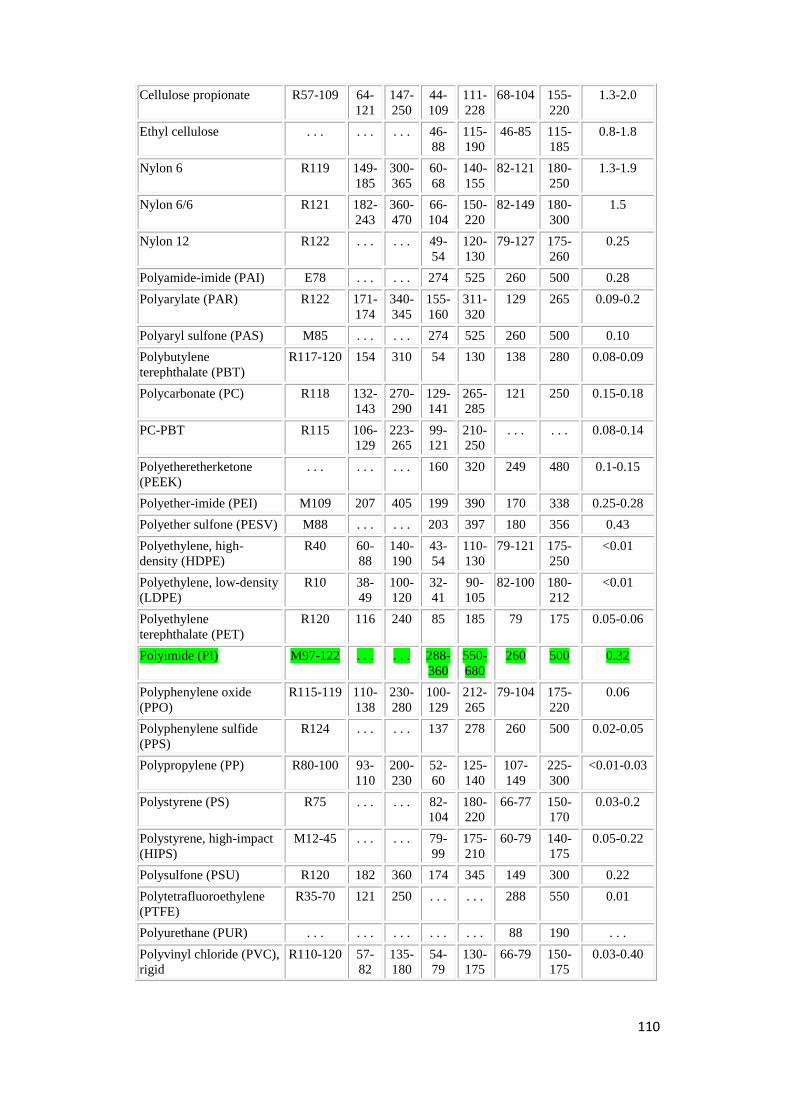
110
Cellulose propionate R57-109 64-
121
147-
250
44-
109
111-
228
68-104 155-
220
1.3-2.0
Ethyl cellulose . . . . . . . . . 46-
88
115-
190
46-85 115-
185
0.8-1.8
Nylon 6 R119 149-
185
300-
365
60-
68
140-
155
82-121 180-
250
1.3-1.9
Nylon 6/6 R121 182-
243
360-
470
66-
104
150-
220
82-149 180-
300
1.5
Nylon 12 R122 . . . . . . 49-
54
120-
130
79-127 175-
260
0.25
Polyamide-imide (PAI) E78 . . . . . . 274 525 260 500 0.28
Polyarylate (PAR) R122 171-
174
340-
345
155-
160
311-
320
129 265 0.09-0.2
Polyaryl sulfone (PAS) M85 . . . . . . 274 525 260 500 0.10
Polybutylene
terephthalate (PBT)
R117-120 154 310 54 130 138 280 0.08-0.09
Polycarbonate (PC) R118 132-
143
270-
290
129-
141
265-
285
121 250 0.15-0.18
PC-PBT R115 106-
129
223-
265
99-
121
210-
250
. . . . . . 0.08-0.14
Polyetheretherketone
(PEEK)
. . . . . . . . . 160 320 249 480 0.1-0.15
Polyether-imide (PEI) M109 207 405 199 390 170 338 0.25-0.28
Polyether sulfone (PESV) M88 . . . . . . 203 397 180 356 0.43
Polyethylene, high-
density (HDPE)
R40 60-
88
140-
190
43-
54
110-
130
79-121 175-
250
<0.01
Polyethylene, low-density
(LDPE)
R10 38-
49
100-
120
32-
41
90-
105
82-100 180-
212
<0.01
Polyethylene
terephthalate (PET)
R120 116 240 85 185 79 175 0.05-0.06
Polyimide (PI) M97-122 . . . . . . 288-
360
550-
680
260 500 0.32
Polyphenylene oxide
(PPO)
R115-119 110-
138
230-
280
100-
129
212-
265
79-104 175-
220
0.06
Polyphenylene sulfide
(PPS)
R124 . . . . . . 137 278 260 500 0.02-0.05
Polypropylene (PP) R80-100 93-
110
200-
230
52-
60
125-
140
107-
149
225-
300
<0.01-0.03
Polystyrene (PS) R75 . . . . . . 82-
104
180-
220
66-77 150-
170
0.03-0.2
Polystyrene, high-impact
(HIPS)
M12-45 . . . . . . 79-
99
175-
210
60-79 140-
175
0.05-0.22
Polysulfone (PSU) R120 182 360 174 345 149 300 0.22
Polytetrafluoroethylene
(PTFE)
R35-70 121 250 . . . . . . 288 550 0.01
Polyurethane (PUR) . . . . . . . . . . . . . . . 88 190 . . .
Polyvinyl chloride (PVC),
rigid
R110-120 57-
82
135-
180
54-
79
130-
175
66-79 150-
175
0.03-0.40

111
PVC, flexible . . . . . . . . . . . . . . . 60-79 140-
175
0.2-1.0
Styrene-acrylonitrile
(SAN)
M80 . . . . . . 88-
104
190-
220
60-93 140-
200
0.20-0.35
Styrene-maleic anhydride
(S/MA)
R95 . . . . . . 96-
127
205-
260
93 200 0.5

112
Appendix I – MATLAB dynamics code for actuator
% GABRIEL A MARTIN - SCRIPT FOR ITERATIVE PROCESS TO FIND PRESSURE
CHANGE
% WITH RESPECT TO ACTUATOR POSITION, VELOCITY AND ACCELERATION -
2/8/2016
% STAGE 1 - DEFINE KNOWN PARAMETERS
clear all
clc
P = 0; % ACTUATOR PRESSURE IN PA
Xp = 0; % ACTUATOR POSITION RELATIVE TO ORIGIN (m)
Xpdot = 0; % ACTUATOR VELOCITY (m/s)
k = 1.4; % CONSTANT
Po = 1e+6; % SUPPLY PRESSURE IN PA
R = 287; % GAS CONSTANT
To = 300; % AMBIENT/SUPPLY TEMPERATURE IN KELVIN
Av = 1.9635e-5; % EFFECTIVE CROSS-SECTIONAL AREA OF VALVE INLET
(m^2) -
% at the moment this area will be assumed to be
fixed
% i.e. either fully open or closed (5mm
diameter)
Ap = 0.00503; % AREA OF PRESSURE-SIDE OF ACTUATOR (m^2)
DT = 0.0001; % Time step (seconds)
t1=0; % Initial iteration
M=11; % mass of actuator in kg
a=1.2; % Both a and ain are constants describing heat
transfer
ain=1.39; % characteristics
Vd = 1.32409e-6 + 0.0025*Ap; % dead chamber volume in m^3
F=14; % Dynamic Friction force from O-rings (N)
Mg=9.81*M; % actuator weight
% STAGE 2 - DEFINE FORMULAE FOR ACCELERATING FROM STAND-STILL.
This starts
% the iterative loop:
while Xp<=0.040 % condition restricting actuator to travel
stroke length
if Xpdot<0.5
% NEWTON'S LAW:
Xpdotdot = ((Ap.*P)-F-Mg)./M; % ACCELERATION OF ACTUATOR FOR A
SPECIFIC TIME-STEP (m/s^2)
if Xpdotdot<=0
Xpdotdot=0;
elseif Xpdotdot>0
Xpdotdot = ((Ap.*P)-F-Mg)./M;
end
Xpdot = Xpdot + Xpdotdot.*DT;
Xp = Xp +((Xpdot.*DT)./2);
% Changing volume with respect to displacement:
V = Ap.*Xp;
% Stage 3 - define formulae for pressure derivative (depends on
mfr).
% Includes conditional loop which changes lambda value if pressure
ratio
% exceeds 0.53.

113
if P<=0.53*Po; % choked flow
lambda=0.58; % Lambda value for critical flow limit
elseif P>0.53*Po; % under-choked
lambda=sqrt(2./(k-
1)).*(P./Po).^((k+1)./(2*k)).*sqrt(((P./Po).^...
((1-k)./k))-1);
end
mfr=lambda.*sqrt(k./(R.*To)).*Po.*Av; % mass flow rate of air
(kg/s)
% Pressure derivative (pressure change with respect to time -
% Pascals/second).
Pdot = (ain.*mfr.*((R.*To)./(Vd+V)))-
(a.*Xpdot.*((Ap.*P)./(Vd+V)));
% Define new pressure in chamber based on pressure rate:
P = Pdot.*DT+P;
% This nested loop calculates the variables with time when
velocity is
% constant at 0.5 m/s.
elseif Xpdot>=0.5
Xpdotdot = ((Ap.*P)-F-Mg)./M;
Xpdot = Xpdot + Xpdotdot.*DT;
Xp = Xp +((Xpdot.*DT)./2);
V = Ap.*Xp;
if P<=0.53*Po; % choked flow
lambda=0.58; % Lambda value for critical flow limit
elseif P>0.53*Po; % under-choked
lambda=sqrt(2./(k-
1)).*(P./Po).^((k+1)./(2*k)).*sqrt(((P./Po).^...
((1-k)./k))-1);
end
Av=6.8027e-8;
mfr=lambda.*sqrt(k./(R.*To)).*Po.*Av; % mass flow rate of air
(kg/s)
Pdot = (ain.*mfr.*((R.*To)./(Vd+V)))-
(a.*Xpdot.*((Ap.*P)./(Vd+V)));
P = Pdot.*DT+P;
end
% total time taken:
t1=t1+1;
T1=t1.*DT;
% stage 4 - plot graphs
subplot(2,3,1)
plot(t1,P,'b+')
hold on
title('Pressure vs time')
xlabel('x10^-4 sec')
ylabel('Pa')
subplot(2,3,2)
plot(t1,mfr,'g+')
hold on
title('Flow rate vs time')
xlabel('x10^-4 sec')
ylabel('kg/s')
subplot(2,3,3)

114
plot(t1,Xp,'ro')
hold on
title('Position vs time')
xlabel('x10^-4 sec')
ylabel('m')
subplot(2,3,4)
plot(t1,Xpdot,'go')
hold on
title('Velocity vs time')
xlabel('x10^-4 sec')
ylabel('m/s')
subplot(2,3,5)
plot(t1,Xpdotdot,'yo')
hold on
title('Acceleration vs time')
xlabel('x10^-4 sec')
ylabel('m/s^2')
subplot(2,3,6)
plot(t1,lambda,'ko')
hold on
title('lambda vs time')
xlabel('x10^-4 sec')
ylabel('lambda')
end
% Display overall time for actuation in seconds in command window:
disp('total time taken (seconds):');
disp(T1);

115
Appendix J – Parker ECI Metal C-ring Internal Pressure Face Seal
data

116

117

118
Appendix K – MATLAB code for bearing deflection in edge-loaded
case
% GABRIEL A MARTIN - SCRIPT FOR ITERATIVE CALULATION OF
BEARING DEFLECTION
% AND BEARING CONSTANT 'MU' - 16/8/2016
clc
clear all
% The first stage is to guess a deflection value dm (mm) for
the edge of
% the bearing. Next the guessed value is substituted into
the equation
% for 'eta'. When eta is calculated, it is substituted into
constant Keta.
% Keta is put into equation for dm. dm is recalculated. If
dm turns out
% to be different to the initial guess for dm by a certain
tolerance, the
% above steps are reiterated. Reiteration occurs until both
values for dm
% diverge to be within the set tolerance.
% PARAMETERS:
dm=0.1; % initial guess for bearing deflection at
edge in mm
D=142.063; % bore diameter in mm
psi=2.58055e-3; % ratio of bearing running clearance mm to
shaft diameter
% (mm)
Ec=992.844; % compressive modulus of bearing material
in MPa
W=2.2606; % bearing wall thickness mm
S=tand(1.692); % slope of shaft relative to bearing
Fc=16.368; % Applied side load on bearing (N)
mu=0.46; % Poisson Ratio
Kmu=(1-mu)/((1+mu)*(1-2*mu)); % constant based on Poisson's
ratio
% Tolerance:
Delta=1e-10;
% Definition of equation for 'eta':
numerator=((1+psi)^2)+(((2*dm)/(D+psi))^2)-1;
denominator=2*(1+psi)*(((2*dm)/D)+psi);
eta=sqrt(1-(numerator/denominator)^2);
% Define constant into which eta will be substituted:
Keta=0.0959*(eta^3)-0.086*(eta^2)+(0.327*eta)-0.0017;
% Recalculate dm. If different to initial guess, reiterate.
dmnew=sqrt((W*S*Fc)/(Ec*D*Kmu*Keta));
i=1; % iteration number

119
% Below is the reiterative loop. Loop repeats until
difference between dm
% and dmnew becomes less than the tolerance.
while abs(dmnew-dm)>Delta
i=i+1;
dm=dmnew;
numerator=((1+psi)^2)+(((2*dm)/(D+psi))^2)-1;
denominator=2*(1+psi)*(((2*dm)/D)+psi);
eta=sqrt(1-(numerator/denominator)^2);
Keta=0.0959*(eta^3)-0.086*(eta^2)+(0.327*eta)-0.0017;
dmnew = sqrt((W*S*Fc)/(Ec*D*Kmu*Keta));
end
disp('Number of iterations performed were:')
disp(i)
disp('Final deflection at edge in mm is:')
disp(dmnew)
% Now that the solution to dm after several iterations has
been given, the
% solution to peak pressure acting on the bearing can now be
calculated.
pm=Kmu*(Ec/W)*dmnew;
disp('peak pressure (MPa) due to maximum deflection:')
disp(pm)

120
Appendix L – MATLAB code for seal compression
% Gabriel A Martin - Final Year project scriptcode2 - 9/9/2016 % This code simulates the compression of the C-ring gasket after
the % actuator has risen to position. clear all clc
% Define parameters. k = 1.4; % CONSTANT Po = 1e+6; % SUPPLY PRESSURE IN PA R = 287; % GAS CONSTANT To = 300; % AMBIENT/SUPPLY TEMPERATURE IN KELVIN Ap = 0.00503; % AREA OF PRESSURE-SIDE OF ACTUATOR (m^2) DT = 0.0001; % Time step (seconds) t1=0; % Initial iteration M=11; % mass of actuator in kg a=1.2; % Both a and ain are constants describing heat
transfer ain=1.39; % characteristics Vd = 1.32409e-6 + 0.0025*Ap; % dead chamber volume in m^3 F=40; % Dynamic Friction force from O-rings - static
(N) Mg=9.81*M; % actuator weight P=3488.8; % Initial chamber pressure (Pa) Xptotal=0.000254; % Total displacement for actuator to travel (m) Xpold=0.041; % Initial displacement (m) Xpdot=0; Xp=Xpold;
% A while loop is constructed for pressurisation of chamber. The
resultant % pressure must provide the necessary stress on C-ring gasket for
proper % sealing. Final pressure is estimated to be 0.72 MPa (from 3488.8
Pa). while 0.041<=Xp && Xp<0.041254
% This section calculates variables with flow rate held constant. V = Ap.*Xp; if P<=0.53*Po; % choked flow lambda=0.58; % Lambda value for critical flow limit elseif P>0.53*Po; % under-choked lambda=sqrt(2./(k-
1)).*(P./Po).^((k+1)./(2*k)).*sqrt(((P./Po).^... ((1-k)./k))-1); end
Av=1e-5; mfr=lambda.*sqrt(k./(R.*To)).*Po.*Av; % mass flow rate of air
(kg/s) Pdot = (ain.*mfr.*((R.*To)./(Vd+V)))-
(a.*Xpdot.*((Ap.*P)./(Vd+V))); P = Pdot.*DT+P;
Xpstrain=(Xp-Xpold)./Xptotal; % strain/percentage of total
displacement FR=3622*Xpstrain; % Resistive force from C-ring based on
strain (N)

121
Xpdotdot = ((Ap.*P)-F-Mg-FR)./M; if Xpdotdot<0 Xpdotdot=0; elseif Xpdotdot>=0 Xpdotdot = ((Ap.*P)-F-Mg-FR)./M; end Xpdot = Xpdot + Xpdotdot.*DT; Xp = Xp +((Xpdot.*DT)./2);
% total time taken: t1=t1+1; T1=t1.*DT;
% stage 4 - plot graphs subplot(2,2,1) plot(t1,P,'b+') hold on title('Pressure vs time') xlabel('x10^-4 sec') ylabel('Pa')
subplot(2,2,2) plot(t1,mfr,'g+') hold on title('Flow rate vs time') xlabel('x10^-4 sec') ylabel('kg/s')
subplot(2,2,3) plot(t1,Xp,'ro') hold on title('Position vs time') xlabel('x10^-4 sec') ylabel('m')
subplot(2,2,4) plot(t1,Xpdot,'go') hold on title('Velocity vs time') xlabel('x10^-4 sec') ylabel('m/s')
end
% Display overall time for actuation in seconds in command window: disp('total time taken (seconds):'); disp(T1);

122
Appendix M – MATLAB code for discharge
% Gabriel A Martin - Final Year project scriptcode3 - 18/9/2016 % Code for chamber pressure discharge. Actuator descends due to
gravity. clear all clc
% Define parameters. k = 1.4; % CONSTANT R = 287; % GAS CONSTANT T = 300; % CHAMBER TEMPERATURE IN KELVIN Ap = 0.00503; % AREA OF PRESSURE-SIDE OF ACTUATOR (m^2) DT = 0.0001; % Time step (seconds) t1=0; % Initial iteration M=11; % mass of actuator in kg a=1.2; % Both a and ain are constants describing heat
transfer aout=1.01; % characteristics Vd = 1.32409e-6 + 0.0025*Ap; % dead chamber volume in m^3 F=40; % Dynamic Friction force from O-rings - static
(N) Mg=9.81*M; % actuator weight P=7.2e+5; % Initial chamber pressure (Pa) - GAUGE Patm=0; % ATMOSPHERIC PRESSURE (Pa) - GAUGE Xp=0.041254; % Initial displacement (m) Xpdot=0; % Initial velocity m/s
% While loop iteratively calculates dynamics of actuator during % depressurisation. while Xp<=0.041254 && Xp>0
% This section calculates variables with flow rate held constant. Xpdotdot = ((Ap.*P)+F-Mg)./M; if Xpdotdot>=0 Xpdotdot=0; elseif Xpdotdot<0 Xpdotdot = ((Ap.*P)+F-Mg)./M; % NOTE that F term is positive instead of negative, as
friction % force is always opposite to direction of travel end Xpdot = Xpdot + Xpdotdot.*DT; Xp = Xp +((Xpdot.*DT)./2);
V = Ap.*Xp; if Patm<=0.53*P; % choked flow lambda=0.58; % Lambda value for critical flow limit elseif Patm>0.53*P; % under-choked lambda=sqrt(2./(k-1)).*(Patm./P).^((k+1)./(2*k)).*sqrt... (((Patm./P).^((1-k)./k))-1); end
Av=5e-5; % This valve area is for the exhaust path mfr=lambda.*sqrt(k./(R.*T)).*P.*Av; % mass flow rate of air
exiting % chamber (kg/s)
Pdot = (a.*Xpdot.*((Ap.*P)./(Vd+V)))-
(aout.*mfr.*((R.*T)./(Vd+V)));

123
% Pdot terms above have their senses reversed due to discharge
scenario P = Pdot.*DT+P;
% total time taken: t1=t1+1; T1=t1.*DT;
% stage 4 - plot graph for velocity over time plot(t1,Xpdot,'g+') hold on title('Velocity vs time') xlabel('x10^-4 sec') ylabel('m/s')
end
% Display overall time for actuation in seconds in command window: disp('total time taken (seconds):'); disp(T1);
NOTE: The above code only plots velocity vs time graph. ‘Stage 4’ of this code was
modified to plot each variable individually.

124
Appendix N – Engineering Drawings
The following drawings have been produced for the purpose of illustrating the
modifications to the original components drawn by Kevin Dray (2014) as well as additional
components necessary for the assembly of the pneumatic clamp. Therefore, any other parts
for the engine which have not been modified, have not been included here.


Related Documents