ELEKTRONIKA IR ELEKTROTECHNIKA, ISSN 1392-1215, VOL. 19, NO. 8, 2013 Abstract—The simple GPS methods are unable to retrieve the real-time information of vehicle location and vehicle running state in some special circumstances such as tunnels and built-ups. Hence, the vehicle monitoring system to acquire real- time vehicle information is required. In this paper, by integrating technologies of RFID, GPS, GPRS and using LANDMARC method, an accurate vehicle location system in a variety of complex environments is proposed. The proposal is able to improve the precise vehicle location and get the mechanical information of vehicle status by the technology of wireless data communication. Index Terms—RFID, GPS, GPRS, accurate vehicle location, LANDMARC. I. INTRODUCTION The modernization of transport, currently, is an important criterion to take the measure of urban modernization level. Developments in communication and network technology have been improved highly. Besides, the vehicle location, widely used in the road transport of dangerous goods (RTDG), logistics, armored car and other particular fields, becomes a core position in the modernization of transport. Thus, it is a hot research point. Triangulation, scene analysis, and proximity are the three principal techniques for automatic location-sensing [1]. One of the most important technologies of location systems is Global Positioning System (GPS), a satellite-based navigation system made up of a network of 24 satellites placed into orbit [2]. Vehicle location devices with a single GPS technology- based have played an important role on the market [3]. Manuscript received January 1, 2013; accepted May 8, 2013. The research is support by National Natural Science Foundation of P. R. China (Grant No. 61170065 and 61003039), Peak of Six Major Talent in Jiangsu Province (Grant No.2010DZXX026). The authors are grateful to the anonymous referee for a careful checking of the details and for helpful comments that improved this paper. Reliable in-car navigation only becomes possible with high position accuracy and up-to-date map database [4]. However, there are obvious shortcomings by using a simple GPS method in the aspect of positioning accuracy and coverage. Therefore, many researchers pay attention to the combination of GPS and other relevant technology for facilitating accuracy of vehicle location. Many approaches have been proposed as follows. Based on GPS and GSM, Farooq U. [5] proposed and implemented a solution for enhancing public transportation management services in Punjab province of Pakistan. And Thong S.T.S. [6] proposed an intelligent fleet management system. Congshan Qu [7] introduced a GPS and CDMA application system based on embedded Linux operating system. Based on GPS and GPRS, Tao Ning [8] designed the new vehicular monitor system. Yougui Liu [9] achieved vehicle location tracking on Internet by using GPRS vehicle location terminal and combining with Internet technology and GIS technology. Al-Taee M.A. [10] presented a distributed system for remote monitoring of vehicle diagnostics and geographical position. Although above-mentioned researches improved extensions of accuracy on vehicle location system, it is unable to acquire the real-time information of vehicle location and vehicle running state in some areas such as tunnels [11] and built-ups. For example, narrow streets among high-rise buildings blocking GPS signal paths provide limited visibility to satellites and cause multi-path effects. The accuracy of GPS location is not precise and the position drift for vehicle location is large. As a result, the management of vehicle is inconvenient and cannot meet the requirement of a high standard for managers. With respect to developments of RFID technology, it has been widely used in many fields. Several key technologies of RFID, GPS and GPRS are independent and lack of relational connection, so their advantages could not be mingled with Design of Accurate Vehicle Location System Using RFID Y. Ning 1,2 , W. Zhong-qin 1 , R. Malekian 3 , W. Ru-chuan 1 , A. H. Abdullah 4 1 Institute of Computer Science, Nanjing University of Post and Telecommunications, Nanjing, China 2 Department of Information Science, Nanjing College for Population Programme Management, Nanjing, China 3 Advanced Sensor Networks Research Group, Department of Electrical, Electronic and Computer Engineering, University of Pretoria, Pretoria, 0002, South Africa 4 Faculty of Computing, Universiti Teknologi Malaysia, Johor, Malaysia [email protected] http://dx.doi.org/10.5755/j01.eee.19.8.5405 105

Welcome message from author
This document is posted to help you gain knowledge. Please leave a comment to let me know what you think about it! Share it to your friends and learn new things together.
Transcript
ELEKTRONIKA IR ELEKTROTECHNIKA, ISSN 1392-1215, VOL. 19, NO. 8, 2013
Abstract—The simple GPS methods are unable to retrieve
the real-time information of vehicle location and vehicle
running state in some special circumstances such as tunnels and
built-ups. Hence, the vehicle monitoring system to acquire real-
time vehicle information is required. In this paper, by
integrating technologies of RFID, GPS, GPRS and using
LANDMARC method, an accurate vehicle location system in a
variety of complex environments is proposed. The proposal is
able to improve the precise vehicle location and get the
mechanical information of vehicle status by the technology of
wireless data communication.
Index Terms—RFID, GPS, GPRS, accurate vehicle location,
LANDMARC.
I. INTRODUCTION
The modernization of transport, currently, is an important
criterion to take the measure of urban modernization level.
Developments in communication and network technology
have been improved highly. Besides, the vehicle location,
widely used in the road transport of dangerous goods
(RTDG), logistics, armored car and other particular fields,
becomes a core position in the modernization of transport.
Thus, it is a hot research point.
Triangulation, scene analysis, and proximity are the three
principal techniques for automatic location-sensing [1]. One
of the most important technologies of location systems is
Global Positioning System (GPS), a satellite-based
navigation system made up of a network of 24 satellites
placed into orbit [2].
Vehicle location devices with a single GPS technology-
based have played an important role on the market [3].
Manuscript received January 1, 2013; accepted May 8, 2013.
The research is support by National Natural Science Foundation of P.
R. China (Grant No. 61170065 and 61003039), Peak of Six Major Talent
in Jiangsu Province (Grant No.2010DZXX026). The authors are grateful to
the anonymous referee for a careful checking of the details and for helpful
comments that improved this paper.
Reliable in-car navigation only becomes possible with high
position accuracy and up-to-date map database [4].
However, there are obvious shortcomings by using a simple
GPS method in the aspect of positioning accuracy and
coverage.
Therefore, many researchers pay attention to the
combination of GPS and other relevant technology for
facilitating accuracy of vehicle location. Many approaches
have been proposed as follows.
Based on GPS and GSM, Farooq U. [5] proposed and
implemented a solution for enhancing public transportation
management services in Punjab province of Pakistan. And
Thong S.T.S. [6] proposed an intelligent fleet management
system. Congshan Qu [7] introduced a GPS and CDMA
application system based on embedded Linux operating
system.
Based on GPS and GPRS, Tao Ning [8] designed the new
vehicular monitor system. Yougui Liu [9] achieved vehicle
location tracking on Internet by using GPRS vehicle location
terminal and combining with Internet technology and GIS
technology. Al-Taee M.A. [10] presented a distributed
system for remote monitoring of vehicle diagnostics and
geographical position.
Although above-mentioned researches improved
extensions of accuracy on vehicle location system, it is
unable to acquire the real-time information of vehicle
location and vehicle running state in some areas such as
tunnels [11] and built-ups. For example, narrow streets
among high-rise buildings blocking GPS signal paths
provide limited visibility to satellites and cause multi-path
effects. The accuracy of GPS location is not precise and the
position drift for vehicle location is large. As a result, the
management of vehicle is inconvenient and cannot meet the
requirement of a high standard for managers.
With respect to developments of RFID technology, it has
been widely used in many fields. Several key technologies of
RFID, GPS and GPRS are independent and lack of relational
connection, so their advantages could not be mingled with
Design of Accurate Vehicle Location System
Using RFID
Y. Ning1,2
, W. Zhong-qin1, R. Malekian
3, W. Ru-chuan
1, A. H. Abdullah
4
1Institute of Computer Science, Nanjing University of Post and Telecommunications,
Nanjing, China 2Department of Information Science, Nanjing College for Population Programme Management,
Nanjing, China 3Advanced Sensor Networks Research Group, Department of Electrical, Electronic and Computer
Engineering, University of Pretoria,
Pretoria, 0002, South Africa 4Faculty of Computing, Universiti Teknologi Malaysia,
Johor, Malaysia
http://dx.doi.org/10.5755/j01.eee.19.8.5405
105
ELEKTRONIKA IR ELEKTROTECHNIKA, ISSN 1392-1215, VOL. 19, NO. 8, 2013
each other.
In response to such problems, by integrating with the
technology of RFID, GPS, GPRS, an accurate vehicle
location system in a variety of complex environments is
proposed in this paper, which is able to improve the precise
vehicle location and get the mechanical information of
vehicle status by the technology of wireless data
communication.
The rest of this paper is organized as follows. In Section
II, a brief overview of RFID technology is given as
background information. The LANDMARC approach shows
in Section III. In Section IV, the scheme of accurate vehicle
location system is given. Section V and VI, introduces the
designation of accurate vehicle location system, including
hardware and software. The experimental result is analyzed
in Section VII. Finally, conclusions and future works are
described in Section VIII.
II. RFID BACKGROUND
RFID is not a new technology. RFID technology is one of
the pivotal enablers of the “Internet of Things” [12]. Today
RFID is a generic term for technologies that use radio waves
to automatically identify people or objects [13] and have
revolutionized automatic identification and data capture
technologies [14]. The system comprises two separate
components, namely a transponder or tag usually located on
the item to be identified or tracked and an interrogator or
reader [15].
A tag (or a transponder) can include other information
which opens up opportunities to other new application areas
except the ID. RFID tags fall into two main categories:
Active and Passive. Passive tags do not contain a battery or
power source. Active tags have internal batteries and thus
can work for longer distances as they do not depend on near
field or the interrogator to transmit or receive [16].
An RFID reader together with an antenna can read (or
interrogates) and write tags. A reader detects the tags that is
attached to or embedded in the selected items. It varies in
location, size and other information. The reader
communicates with the tag through the reader antenna,
which broadcasts radio waves and receives the tags response
signals within its reading area. After the signals from tags
are detected, the reader decodes them and passes the
information to middleware [17]. In the process of making the
tag identification, a reader first sends a request signal to tags
in its field, and then the tags, which received the request
signal, respond by sending their ID to the reader
immediately [18].
RFID systems mostly utilize Low Frequency (LF) at 125-
134 kHz, High Frequency (HF) at 13.56 MHz, and Ultra
High Frequency at 433 MHz and 860 MHz to 930 MHz and
more recently Microwave Frequencies at 2.45 GHz [19].
The communication range with the tags in an RFID system is
mainly determined by the output power of the reader.
The field from an antenna extends into the space and its
strength diminishes with respect to the distance to tags. The
antenna design determines the shape of the field so that the
range is also influenced by the beam pattern between the tag
and antenna.
III. LANDMARC APPROACH
The LANDMARC algorithm comes from an active RFID
indoor positioning System. Due to some special
circumstances such as tunnels and built-ups, the region can
be seen as indoor situation by us. So the LANDMARC
should be adapted into our vehicle position system.
The method of LANDMARC uses additional fixing the
position of the reference tag to help position calibration and
the reference tag are regarded as a reference point in the
system (such as landmark in our lives). The main advantage
of this approach is that it does not require a lot of expensive
RFID reader, instead of using the extra cheap RFID tags.
The algorithm of using the nearest neighbor data to improve
the positioning accuracy of the system is essential for
LANDMARC algorithm which is based on indoor
positioning system introduced reference tags. The reader and
method of placing reference tags, obviously, influence the
overall system accuracy.
In the LANDMARC algorithm [20], suppose that there
are n RFID readers along with m tags as reference tags and u
tracking tags as objects being tracked and defined the Signal
Strength Vector of a tracking/moving tag as S= (S1, S2, …,
Sn) where Si denotes the signal strength of the tracking tag
perceived on reader I where i∈( 1, n). We regard tracking
tag u as tag of the road where vehicle will pass by and regard
reference tag m as the tag of road closed to tracking tag u.
We also consider the Signal Strength Vector S of a
tracking/moving tag as frequency of reading tracking tags u.
For the reference tags, the author denotes the
corresponding Signal Strength vector as θ= (θ1, θ2, …, θn)
where θi denotes the signal strength. We also consider θ as
frequency of reading reference tags m. For each individual
tracking tag p they define
2
1
( ) (1, ).n
j i ii
E S j mθ=
= − ∈∑ (1)
Based on Euclidean distance between two points P and Q
is the length of the line segment connecting them i.e., PQ .
If we assume P= (p1, p2,…, pn) and Q= (q1, q2,…, qn) are
two points in Euclidean metrics, then distance between P and
Q is given by
2 2 21 1 2 2( , ) ( ) ( ) ... ( ) ,n nd P Q q p q p q p= − + − + + − (2)
results in
2
1
( , ) ( ) .n
i ii
d P Q q p=
= −∑ (3)
The position of a point in Euclidean n-space is a
Euclidean vector. Therefore, P and Q are Euclidean vectors.
Euclidean length of a vector can be measured as following
2 2 21 2|| || ... . .nP p p p p p= + + + = (4)
Similarly
106
ELEKTRONIKA IR ELEKTROTECHNIKA, ISSN 1392-1215, VOL. 19, NO. 8, 2013
2 2 21 2|| || ... . .nQ q q q q q= + + + = (5)
A vector can be described as a directed line segment from
the origin of the Euclidean space to another point in that
space. Thus, the distance between points P and Q may have
a direction which can be shown by a vector given by
|| || ( ).( ),Q P Q P Q P− = − − (6)
which results in
2 2|| || || || || || 2 . ,q p P Q P Q− = + − (7)
as the Euclidean distance in signal strength between a
tracking tag and a reference tag rj. Let E denote the location
relationship between the reference tags and the tracking tag,
i.e., the nearer reference tag to the tracking tag is supposed
to have a smaller E value. When there are m reference tags, a
tracking tag has its E vector as E= (E1, E2,…, En).
The simplest way to find the nearest reference tag to the
tracking tag is to use the coordinate of the reference tag with
the smallest E value as the unknown tag’s coordinate, called
this as1-nearest neighbor algorithm.
The unknown tracking tag’s coordinate (x, y) is obtained
by
1
( , ) ( ),k
i i ii
x y w x y=
= −∑ (8)
where wi and (xi, yi) is the weighting factor to the ith
neighboring reference tag and coordinate position.
Empirically, in LANDMARC, weight is given by
2
2
1
1/(1, ).i
j k
ii
Ew j m
E=
= ∈
∑
(9)
It may be explained by the fact that the signal strength is
inverse proportional to the square of the distance.
Consequently, the LANDMARC algorithm can be used
into our project rationally and effectively by the appropriate
conversion of scene.
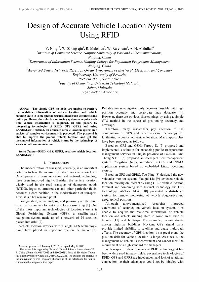
IV. FRAMEWORK OF ACCURATE VEHICLE LOCATION
SYSTEM
The system architecture consists of four layers to regulate
the vehicle location system, which are a physical layer, a
device layer, a data transmission layer and an application
layer. The framework is shown in Fig. 1.
A. Physical layer
The physical layer mainly consists of passive tags. The
vehicle equipped with a controller sends electromagnetic
waves to tags and retrieves the position information from
tags. RFID tags are installed along lanes on a road in a
manner which could maximize the coverage and the
accuracy of position.
B. Device layer
The device is a vehicle controller, mainly composed by a
RFID module, a GPRS module, a GPS module and a sensing
module. It is the core of entire vehicle location system,
which is used to collect and transfers information. The
functions of device are the collection of ID information,
GPS position and vehicle status, storage and transmission of
that information to the management center and cloud by
GPRS network.
Fig. 1. Architecture of vehicle location system.
C. Data transmission layer
The main function of this layer can be used to transmit the
data collected from the device layer by GPRS network.
RFID tag’s transmission rate is 256 kbps.
D. Application layer
Based on above layers’ data and knowledge, the
application layer, included the management center and
cloud, can fulfill the mission to monitor and manage remote
vehicles.
The cloud has a powerful function of processing,
analyzing and storing the information, which involve
position, vehicle status and real-time circumstance.
Furthermore, the results of computing information from
cloud terminal could give the administrator many effective
suggestions. We will investigate and pay attention to this
part in the future.
V. DESIGN OF ACCURATE VEHICLE LOCATION SYSTEM-
HARDWARE DESIGN
A. RFID Tag
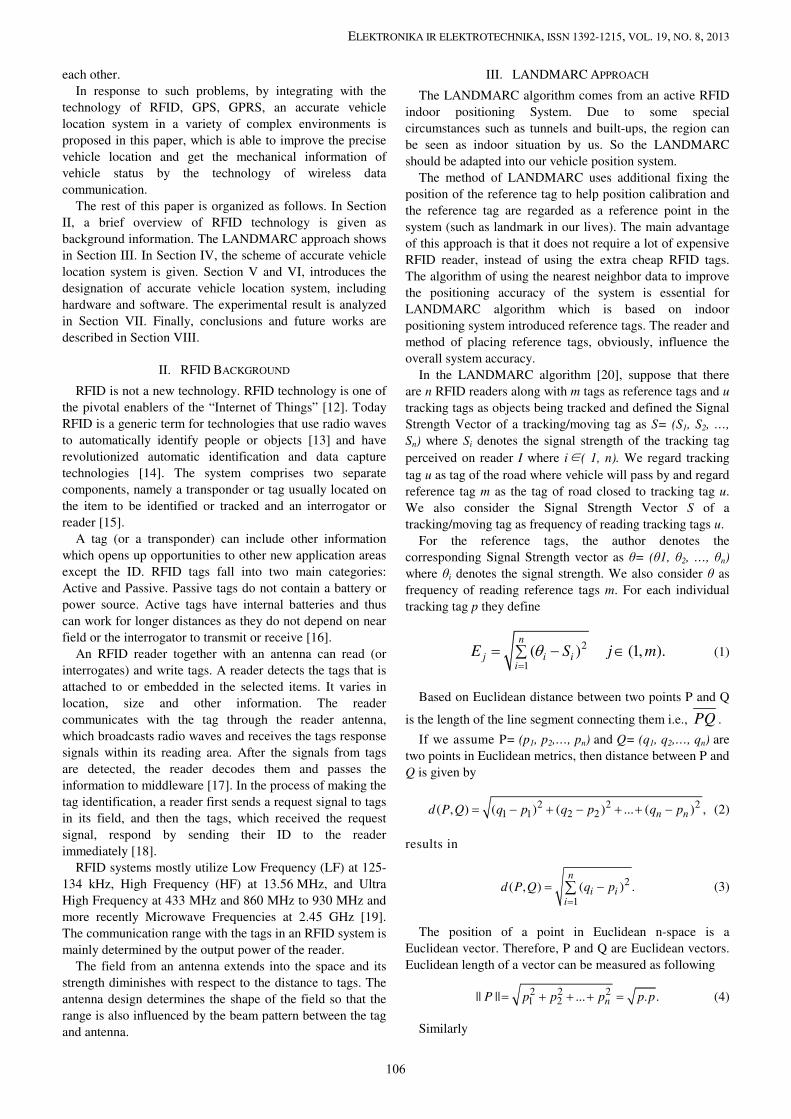
1) Data storage in tag memory
A RFID tag memory is logically separated into four
distinct banks, each of which comprises zero or more
memory words. A logical memory map contains reserved
memory, EPC memory, TID memory and user memory. And
user memory allows user-specific data storage, thus, the
107

ELEKTRONIKA IR ELEKTROTECHNIKA, ISSN 1392-1215, VOL. 19, NO. 8, 2013
location information mainly store in that memory map. A tag
with Higgs-3 core has 512-bits of user memory for
distributed data applications. Figure 2 shows a waterproof
tag we have applied in the project. The format of location
information in user memory is shown in Fig. 3.
Fig. 2. Tag agreement.
Fig. 3. Format of location information.
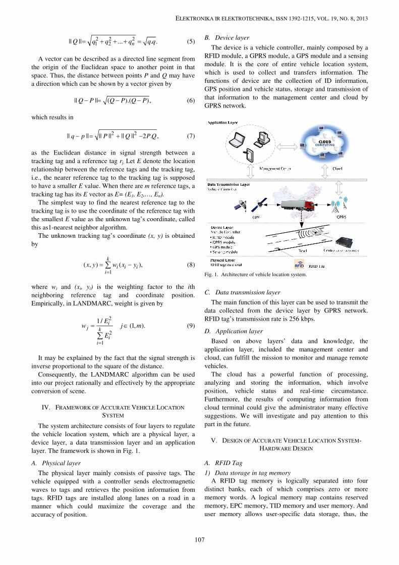
2) Tag Arrangement
We force on the tag arrangement on the road. According
to different practical requirements, there are many methods
of tag arrangement. Enzhan Zhang [21] presented the
scheme called Active RFID Positioning (ARP). The
proposal focused on tag and reader installation, positioning
precision, and evaluated the relationship among reading
range, vehicle speed, tag installation and inter-tag distance.
Due to proposed theory, we arrange RFID tags along the
road in Fig. 4 and match with the contacting time and
vehicle speed, and balance the per cost and precision.
Finally, we set the distance D of approximately six meters.
Fig. 4. Tag arrangement.
B. Vehicle Controller Components
The hardware of Vehicle Location is composed by power
module, clock module, LED module, RFID module, GPS
module, GSM module, sensing module and core controlling
module. The structure of vehicle controller is shown in
Fig. 5 and the vehicle controller is shown in Fig. 6. The
fundamental function of above components is as follows:
1) A power module is used to mange, afford the power.
2) A clock module provides the basic clock signal for core
controlling module.
3) A LED indicator displays the system state through
different flicker.
4) A RFID module reads the information of RFID tags.
5) A sensing module is used to sense the state of
environment and vehicle equipment. When vehicles
encounter the severe turbulence, strong electromagnetic
interference and sudden power-down, the controller will
automatically save the current information and shut down for
protection. If the environment status resume normally, the
controller will continue to work.
Core controlling module
Clock module LED module
GPS module GPRS module
Power
module
RFID module
Sensing
module
Fig. 5. Structure of vehicle controller.
Fig. 6. Vehicle controller.
Fig. 7. Work flowchart of vehicle controller.
108
ELEKTRONIKA IR ELEKTROTECHNIKA, ISSN 1392-1215, VOL. 19, NO. 8, 2013
A GPRS module is the core module of real-time
monitoring vehicle system for automatically connecting the
GPRS network after booting, automatically reconnecting to
the network and uploading data. As a result, it can achieve
the function of connecting the network and sending
information.
(1) A GPS module is used to locate the vehicle through
the GPS global positioning system. It can acquire the
information of vehicle location, current time and vehicle
movement speed, etc.
(2) A core controlling module is used to achieve
functions of tag data proofreading, reader coordination, data
transmission, data storage and task management.
Figure 7 shows the work flowchart of vehicle controller.
When the vehicle is traveling in tunnels, underground
parking and other circumstance that traditional GPS cannot
be accurately positioned, the controller mounting on the
vehicle starts the RFID module to read RFID tags on the
road. And the information of tags and vehicle status store in
the controller memory cell. After reconnecting to the
network, the controller will continue to transmit data and
upload it to the cloud terminal and management center.
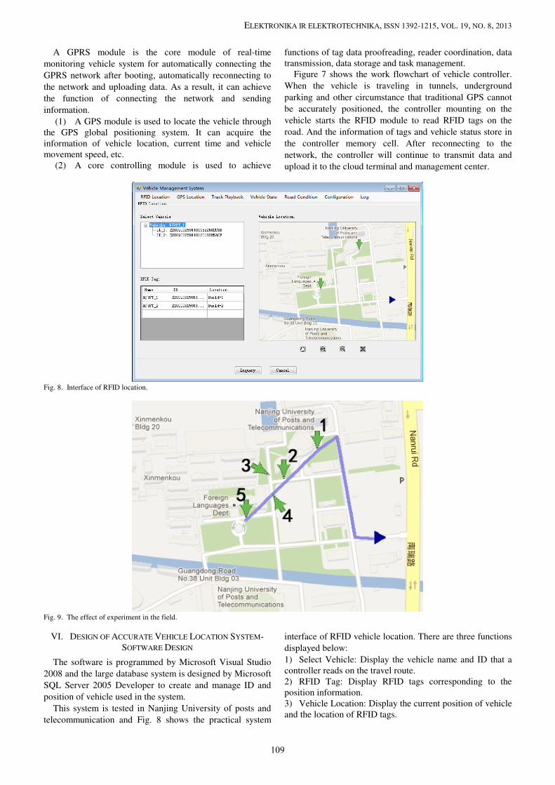
Fig. 8. Interface of RFID location.
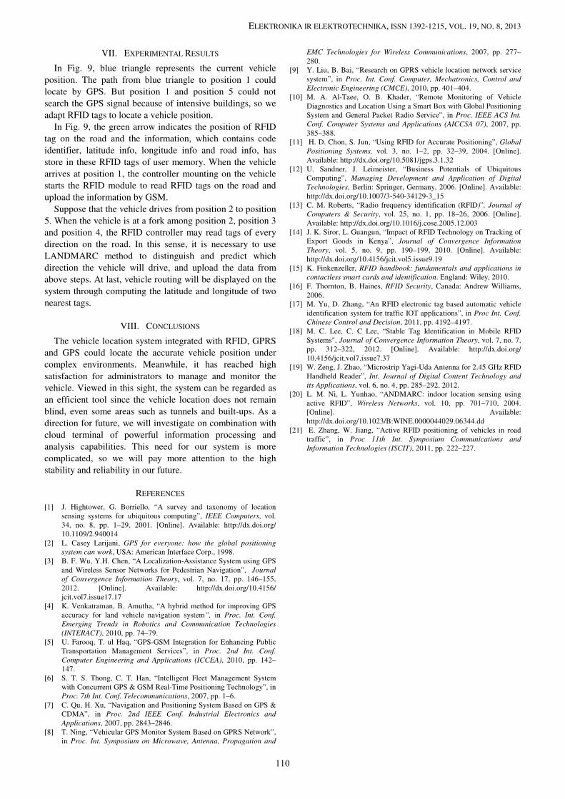
Fig. 9. The effect of experiment in the field.
VI. DESIGN OF ACCURATE VEHICLE LOCATION SYSTEM-
SOFTWARE DESIGN
The software is programmed by Microsoft Visual Studio
2008 and the large database system is designed by Microsoft
SQL Server 2005 Developer to create and manage ID and
position of vehicle used in the system.
This system is tested in Nanjing University of posts and
telecommunication and Fig. 8 shows the practical system
interface of RFID vehicle location. There are three functions
displayed below:
1) Select Vehicle: Display the vehicle name and ID that a
controller reads on the travel route.
2) RFID Tag: Display RFID tags corresponding to the
position information.
3) Vehicle Location: Display the current position of vehicle
and the location of RFID tags.
109
ELEKTRONIKA IR ELEKTROTECHNIKA, ISSN 1392-1215, VOL. 19, NO. 8, 2013
VII. EXPERIMENTAL RESULTS
In Fig. 9, blue triangle represents the current vehicle
position. The path from blue triangle to position 1 could
locate by GPS. But position 1 and position 5 could not
search the GPS signal because of intensive buildings, so we
adapt RFID tags to locate a vehicle position.
In Fig. 9, the green arrow indicates the position of RFID
tag on the road and the information, which contains code
identifier, latitude info, longitude info and road info, has
store in these RFID tags of user memory. When the vehicle
arrives at position 1, the controller mounting on the vehicle
starts the RFID module to read RFID tags on the road and
upload the information by GSM.
Suppose that the vehicle drives from position 2 to position
5. When the vehicle is at a fork among position 2, position 3
and position 4, the RFID controller may read tags of every
direction on the road. In this sense, it is necessary to use
LANDMARC method to distinguish and predict which
direction the vehicle will drive, and upload the data from
above steps. At last, vehicle routing will be displayed on the
system through computing the latitude and longitude of two
nearest tags.
VIII. CONCLUSIONS
The vehicle location system integrated with RFID, GPRS
and GPS could locate the accurate vehicle position under
complex environments. Meanwhile, it has reached high
satisfaction for administrators to manage and monitor the
vehicle. Viewed in this sight, the system can be regarded as
an efficient tool since the vehicle location does not remain
blind, even some areas such as tunnels and built-ups. As a
direction for future, we will investigate on combination with
cloud terminal of powerful information processing and
analysis capabilities. This need for our system is more
complicated, so we will pay more attention to the high
stability and reliability in our future.
REFERENCES
[1] J. Hightower, G. Borriello, “A survey and taxonomy of location
sensing systems for ubiquitous computing”, IEEE Computers, vol.
34, no. 8, pp. 1–29, 2001. [Online]. Available: http://dx.doi.org/
10.1109/2.940014
[2] L. Casey Larijani, GPS for everyone: how the global positioning
system can work, USA: American Interface Corp., 1998.
[3] B. F. Wu, Y.H. Chen, “A Localization-Assistance System using GPS
and Wireless Sensor Networks for Pedestrian Navigation”, Journal
of Convergence Information Theory, vol. 7, no. 17, pp. 146–155,
2012. [Online]. Available: http://dx.doi.org/10.4156/
jcit.vol7.issue17.17
[4] K. Venkatraman, B. Amutha, “A hybrid method for improving GPS
accuracy for land vehicle navigation system”, in Proc. Int. Conf.
Emerging Trends in Robotics and Communication Technologies
(INTERACT), 2010, pp. 74–79.
[5] U. Farooq, T. ul Haq, “GPS-GSM Integration for Enhancing Public
Transportation Management Services”, in Proc. 2nd Int. Conf.
Computer Engineering and Applications (ICCEA), 2010, pp. 142–
147.
[6] S. T. S. Thong, C. T. Han, “Intelligent Fleet Management System
with Concurrent GPS & GSM Real-Time Positioning Technology”, in
Proc. 7th Int. Conf. Telecommunications, 2007, pp. 1–6.
[7] C. Qu, H. Xu, “Navigation and Positioning System Based on GPS &
CDMA”, in Proc. 2nd IEEE Conf. Industrial Electronics and
Applications, 2007, pp. 2843–2846.
[8] T. Ning, “Vehicular GPS Monitor System Based on GPRS Network”,
in Proc. Int. Symposium on Microwave, Antenna, Propagation and
EMC Technologies for Wireless Communications, 2007, pp. 277–
280.
[9] Y. Liu, B. Bai, “Research on GPRS vehicle location network service
system”, in Proc. Int. Conf. Computer, Mechatronics, Control and
Electronic Engineering (CMCE), 2010, pp. 401–404.
[10] M. A. Al-Taee, O. B. Khader, “Remote Monitoring of Vehicle
Diagnostics and Location Using a Smart Box with Global Positioning
System and General Packet Radio Service”, in Proc. IEEE ACS Int.
Conf. Computer Systems and Applications (AICCSA 07), 2007, pp.
385–388.
[11] H. D. Chon, S. Jun, “Using RFID for Accurate Positioning”, Global
Positioning Systems, vol. 3, no. 1–2, pp. 32–39, 2004. [Online].
Available: http://dx.doi.org/10.5081/jgps.3.1.32
[12] U. Sandner, J. Leimeister, “Business Potentials of Ubiquitous
Computing”, Managing Development and Application of Digital
Technologies, Berlin: Springer, Germany, 2006. [Online]. Available:
http://dx.doi.org/10.1007/3-540-34129-3_15
[13] C. M. Roberts, “Radio frequency identification (RFID)”, Journal of
Computers & Security, vol. 25, no. 1, pp. 18–26, 2006. [Online].
Available: http://dx.doi.org/10.1016/j.cose.2005.12.003
[14] J. K. Siror, L. Guangun, “Impact of RFID Technology on Tracking of
Export Goods in Kenya”, Journal of Convergence Information
Theory, vol. 5, no. 9, pp. 190–199, 2010. [Online]. Available:
http://dx.doi.org/10.4156/jcit.vol5.issue9.19
[15] K. Finkenzeller, RFID handbook: fundamentals and applications in
contactless smart cards and identification. England: Wiley, 2010.
[16] F. Thornton, B. Haines, RFID Security, Canada: Andrew Williams,
2006.
[17] M. Yu, D. Zhang, “An RFID electronic tag based automatic vehicle
identification system for traffic IOT applications”, in Proc Int. Conf.
Chinese Control and Decision, 2011, pp. 4192–4197.
[18] M. C. Lee, C. C Lee, “Stable Tag Identification in Mobile RFID
Systems", Journal of Convergence Information Theory, vol. 7, no. 7,
pp. 312–322, 2012. [Online]. Available: http://dx.doi.org/
10.4156/jcit.vol7.issue7.37
[19] W. Zeng, J. Zhao, “Microstrip Yagi-Uda Antenna for 2.45 GHz RFID
Handheld Reader”, Int. Journal of Digital Content Technology and
its Applications, vol. 6, no. 4, pp. 285–292, 2012.
[20] L. M. Ni, L. Yunhao, “ANDMARC: indoor location sensing using
active RFID”, Wireless Networks, vol. 10, pp. 701–710, 2004.
[Online]. Available:
http://dx.doi.org/10.1023/B:WINE.0000044029.06344.dd
[21] E. Zhang, W. Jiang, “Active RFID positioning of vehicles in road
traffic”, in Proc 11th Int. Symposium Communications and
Information Technologies (ISCIT), 2011, pp. 222–227.
110
Related Documents