DESIGN OF A NEW MODULAR SPACECRAFT PLASMA INTERACTION MODELING SOFTWARE (SPIS) J.-F. Roussel ONERA, 2Av E Belin 31055 Toulouse cedex 4, France Phone: +33 5 62 25 27 35 Fax: +33 5 62 25 25 69 E-mail: [email protected] F. Rogier, M. Lemoine, D. Volpert ONERA G. Rousseau University Paris 7 G. Sookahet, P. Sèng Artenum A. Hilgers ESA Abstract The development of a new software for spacecraft plasma interactions modeling was started in Europe at the end of 2002. This Spacecraft Plasma Interaction Software (SPIS) is developed for and by SPINE community (Spacecraft Plasma Interaction Network in Europe) on an open source basis. The ESA contractors, ONERA, Artenum, and University Paris 7 are in charge of the development of SPIS framework and main numerical modules. SPINE community will be able to add extra modules and apply the code to its needs. The software framework is based on the integration or interfacing with available open source tools for CAD, 2D meshing, 3D meshing, GUI, post-processing and graphical display. The numerical routines will allow the modeling of plasma dynamics (kinetic or fluid, electrostatic with possible extension to electromagnetic) and its coupling with the spacecraft (equivalent circuit approach). The modeling of all types of environments and devices will be allowed (LEO/GEO/PEO…, EP/solar arrays…). The emphasis has been put on the code modularity to allow the interoperability of modules, through an object-oriented approach throughout the code. User requirements were defined in February 2003 (4 th SPINE meeting), major technological choices and top level design were performed in June 2003 (unstructured mesh is the basics, Java language was selected for coding, pre-post/processing tools were chosen). The first release of the framework was in October 2003. The major features of the software framework and of the physical numerical routines are presented in this paper.

Welcome message from author
This document is posted to help you gain knowledge. Please leave a comment to let me know what you think about it! Share it to your friends and learn new things together.
Transcript

DESIGN OF A NEW MODULAR SPACECRAFT PLASMA INTERACTION MODELING SOFTWARE (SPIS)
J.-F. Roussel
ONERA, 2Av E Belin 31055 Toulouse cedex 4, France
Phone: +33 5 62 25 27 35 Fax: +33 5 62 25 25 69
E-mail: [email protected]
F. Rogier, M. Lemoine, D. Volpert ONERA
G. Rousseau
University Paris 7
G. Sookahet, P. Sèng Artenum
A. Hilgers
ESA
Abstract
The development of a new software for spacecraft plasma interactions modeling was started in Europe at the end of 2002. This Spacecraft Plasma Interaction Software (SPIS) is developed for and by SPINE community (Spacecraft Plasma Interaction Network in Europe) on an open source basis. The ESA contractors, ONERA, Artenum, and University Paris 7 are in charge of the development of SPIS framework and main numerical modules. SPINE community will be able to add extra modules and apply the code to its needs. The software framework is based on the integration or interfacing with available open source tools for CAD, 2D meshing, 3D meshing, GUI, post-processing and graphical display. The numerical routines will allow the modeling of plasma dynamics (kinetic or fluid, electrostatic with possible extension to electromagnetic) and its coupling with the spacecraft (equivalent circuit approach). The modeling of all types of environments and devices will be allowed (LEO/GEO/PEO…, EP/solar arrays…). The emphasis has been put on the code modularity to allow the interoperability of modules, through an object-oriented approach throughout the code. User requirements were defined in February 2003 (4th SPINE meeting), major technological choices and top level design were performed in June 2003 (unstructured mesh is the basics, Java language was selected for coding, pre-post/processing tools were chosen). The first release of the framework was in October 2003. The major features of the software framework and of the physical numerical routines are presented in this paper.

Introduction - SPIS Project Background
The interest in spacecraft plasma interaction modeling is almost as old as the discovery of the possibly detrimental effects of high energy plasma on satellites. The first concerns had to do with the integrity of the spacecraft platform, i.e. with its capability to operate normally. They are usually called “technological” (as in the name of this conference). The early issues were due to high level charging in Geostationary Earth Orbit (GEO), then in Polar low Earth Orbit (PEO), and the subsequent ElectroStatic Discharge risk (ESD). More recently extra concerns about plasma interactions with active devices, such as Photo Voltaic Arrays (PVA) and Electric Propulsion (EP), also became of prime importance. A second category of concerns are considered as pertaining to “science” rather than technology. Scientists study earth, planetary, interplanetary and solar environments, and their measurements can be spoiled by plasma effects. The most typical situation is the partial or total alteration of the low energy plasma measurements by even a small charging potential, at the Volt scale (to be compared to the hundreds or thousands of Volts scale of technological issues). Modeling the spacecraft and its local plasma environment may allow to predict and/or avoid detrimental charging as in the technological issues, but may also is some cases help the interpretation of the data by “subtracting” the charging effects from the data. Although the typical charging levels of “technological” and “scientific” issues are very different, many modeling techniques are common and a properly designed simulation code should be able to address both. The need to address both domains is also very clear in Europe where both commercial spacecraft and scientific missions are flown by prime companies and ESA.
Unfortunately there is no simulation code both able to answer these needs and available at Europe level or worldwide. Proprietary codes are by definition not available to any user and suffer from the high costs of development and maintenance by a single company (as e.g. ONERA SILECS code1). Commercial codes do exist, but they are either outdated (early NASCAP/GEO2) or not available in Europe due to US export control regulations (NASCAP-2K3).
These needs are at the origin of SPIS project (Spacecraft Plasma Interaction Software) presented here. Another element of great importance in SPIS project background is the existence of SPINE community. It stands for Spacecraft Plasma Interaction Network in Europe although it is not limited to Europe and involves a few Americans and Japanese. It has been set up in 2000 and has been meeting approximately twice a year since then (see http://www.spis.org). The origin of its members is quite diverse: spacecraft technology, space science, plasma science, computer science… First aiming at exchanging information about spacecraft-plasma interaction physics, flight observations, data, simulation methods and results, needs, etc. SPINE community now plays a central role in the development of SPIS software reported here. This development is both performed for the community and by the community on a collaborative basis.
Moreover, a prototype code, PicUp3D4,5 (J. Forest Ph.D.), was already developed in the context of SPINE community. It first tested some technical tools which were chosen for SPIS (Java, VTK). The activity around PicUp3D (users, extra developers) also demonstrated the interest for such an open collaborative approach.

The first section of this article presents SPIS project objectives. The second section describes the project organization for a collaborative development. The project schedule, including past achievements and future plans, are presented next. Entering a little more into the technical details the last two section respectively deal with the global framework of the code and the object oriented design of the numerical solvers.
SPIS Project Objectives
Since the need of a spacecraft plasma interaction simulation code was clear, that none was
available, and that a lively community existed, it appeared clear that a new code had to be developed in the framework of this SPINE community. SPINE members had the need for the code and could offer some development effort.
In that context, the first objective of the code was to answer the whole set of needs of the community. Beyond the large common basis, different needs were expressed in all domains, ranging from solvers to interactions, or plasma source libraries (environment, artificial sources such as EP…). So, the code had first to be versatile. If all the requirements could not be met in its first versions, its structure should allow the extension of the code to fulfill them later.
The versatility of the code, i.e. its offering different modeling capabilities, could only be
achieved through a good modularity. Beyond answering this first requirement of versatility, modularity also offered other advantages. It is of course known to be a condition for an efficient code maintenance and evolution. But in the framework of SPINE, the major interest of building a modular code was to permit a collaborative development, i.e. allow community members to develop their own modules, to be shared with the whole community through neat imbedding in the global code.
The direct consequence of the modularity requirement was the choice of an open source
policy. Although the interfacing of “black boxes” is possible when their inputs and outputs are well documented, module interfacing at source level is much more efficient and safe. Since no compatibility had to be insured with any inherited black box component, it was decided to enforce open source policy on all developed modules for this new code. It did not mean at all that it had to be developed from scratch since many modules are now available on an open source basis both for pre/post-processing and numerical libraries.
Organisation for a Collaborative Development
The organization of SPIS code development was thus optimized for a collaborative
development within SPINE community. As depicted in figure 1, three major entities were set up to collaborate in the code development.
A contract was first attributed to a contractor consortium after an open competition bidding
phase. The major roles of the contractor are to:
1- propose requirements in a first phase (Dec. 2002 through June 2003)

2-
3-
design a modular software architecture and develop its core modules (framework and basic solvers) in a second phase (June 2003 through June 2004)
support the community for an appropriation and testing of the code in a third phase (June 2004 through June 2005) including the use a of collaborative web platform LibreSource http://www.libresource.org.
The consortium is led by ONERA, the French aerospace research public company, in charge
of project management and coordination, numerical architecture design and core numerical solvers development. Subcontractors are Artenum company, specialized in consulting and development in numerical engineering, in charge of SPIS framework development (pre/post-processing, solvers embedding) and open source consulting, and University Paris 7 for community related consulting.
A board was then set up to supervise the software development, the SDAB (Software Development Advisory Board). It is composed of 1 contractor member, 1 ESA member and 3 community members. It supervises and orients the code development in particular in emitting recommendations when tradeoffs are needed between different possible choices or requirements.
The third entity is SPINE community. For SPIS development, three Working Groups (WGs)
have been set up. Each WG has been defined around a specific subject and a challenging test case related to that topic. In the first phase each WG emits requirements relevant to its domain, then requests specific developments and eventually participates in code validation and development in the third phase, where all resources will be devoted to running the test cases and check the capability of the code to model them, upgrading it if necessary. The three WGs were defined by the following topics and test cases:
- WG1: Sheaths, test case = Cluster spacecraft - WG2: Artificial plasma (mostly EP), test case = SMART 1 - WG3: Material interaction, test cases = high level charging SC (Freja in PEO, Scatha in
GEO) More can be found on SPIS web site http://www.spis.org/spis. about SPIS project
organization

now
Dec 2002 June 2003 June 2004 June 2005
requestsupe
rvi
se
proposition
develop
supportvalidation
development
request
DevelopmentPhase 2
Support Phase 3
RequirementsPhase 1
WGs
Contractor
SPINE community
SDAB
ESA Contractor
Figure 1. SPIS project organization
Schedule: First Achievements - Future
User requirements were first to be defined. A first version was written by the contractor. It was discussed within the community, in particular during 4th SPINE Meeting (Feb. 2003), and upgraded with community feed back (during and after the meeting). The User Requirement Document (URD) is accessible at http://www.spis.org/spis/docs/technical/SPIS_URD.pdf.
The major user requirements were the following:
• Solvers: Poisson, Vlasov (PIC), Poisson-Vlasov coupling, SC circuit, SC-Plasma coupling, possibility to include extra solvers (Maxwell, fluid models for matter…)
• Environment: LEO, GEO, flexible environment model... • Interactions: photo-emission, secondary emission, induced conductivity… basic models
provided, possibility to modify them and add extra models • Sources: Maxwell distributions, electric propulsion… highly customisable • Framework: GUI and command line / scripts, for pre/post-processing and computing • Specific need to handle thin surfaces and wires (solar array, wire-like boom…)
In all of these subject, emphasis was put on modularity. If a capability may be needed but will not be implemented initially, compatibility of the code architecture with its future implementation must be insured.
The next trimester (March – June 2003) was devoted to Software Requirements (SRD) and
top level design. They were finalized after the Preliminary Design Review (PDR) between the contractor and SDAB (June 2003). Major choices for languages and tool choices were performed:
• Java was chosen for numerical modules and part of the framework coding, because:
• An Object Oriented (OO) language was needed for a better modularity • Java is a pure OO-language contrarily to C++

• Benchmark on PicUp modules in Java (Julien Forest) showed that C++/Java speed ratio is only on the order of 1 to 2, and even around 1 for compiled Java
• Jython, a python script language interpreter written in Java (homogeneous with solvers), was
chosen for part of the framework • Pre- and post-processing open source tools to be integrated were chosen.
The major choices for numerical modeling were the following:
• Primary mesh will be unstructured (it does not exclude future usage of structured meshes) • Solvers: Poisson, Vlasov, (spacecraft circuit), etc. will be developed for unstructured mesh • The need of a specific handling of 2D and 1D physical elements was identified as deriving
from the thin surfaces and wires user requirements (not through 3D pizza-boxes or thin cylinders, but through actual 2D and 1D elements). The electric field singularity around a thin wire or a panel edge shall be extracted thanks to specific finite elements, allowing exact particle trajectory integration. This is the only way to properly model plasma dynamics around a singular geometry such as e.g. Cluster wire booms (40 m length versus diameter around 1 mm!)
With the third trimester (June-Sept 2003) started the development phase. A large part of SPIS
framework was implemented:
• pre-processing • some framework capabilities (group handling, scripting…) • solver encapsulation: interfacing with PicUp3D prototype code was performed as a
demonstration (interfacing with SPIS solvers cannot yet be demonstrated since most routines do not exist yet)
The full framework with post-processing capabilities will only be released in November
2003. Concerning the numerical routines, progress was:
• detail design of numerical routines architecture, emphasizing modularity and polymorphism • prototype routines development.
The first SPIS release was presented during 5th SPINE meeting, on September 16-17, 2003. It
is now available at http://www.spis.org/spis/download/software/software.html. It was released under the General Public License (GPL). It is a well known open source license (Linux license for instance) which essentially forces the users of the distributed source code to further distribute these source codes under the same GPL license.
The future milestones are the following:
• Release of full framework in November 2003 (post-processing added) • Release of full SPIS software (framework + solvers) in March 2004, with course on SPIS (6th
SPINE meeting)
• Release of extended SPIS in June 2004 (7th SPINE meeting): the major extension should be the specific handling of 2D and 1D elements (singularity extraction through specific finite elements close to edges or wires for Poisson, analytical particle trajectories close to singularities), although it still need to be confirmed at 6th SPINE meeting.
SPIS Framework
We just sketch here a few technical details of SPIS code framework. It has both a Graphical
User Interface (GUI) and a command line interface with the capability to run scripts (Python script language). Commands can either handle high level objects (example: object = plasma, action = integrate over time t), or address low level objects, achieving a much more detailed tuning of the computation thanks to the perfect encapsulation of Java objects in the Java-coded Python script interpreter called Jython (example: object = Poisson boundary conditions on computation box boundary, action = set it as homogeneous Fourier conditions with local parameter defined so as to mimic a 1/r2 potential decay mimicking potential in a pre-sheath around a sphere).
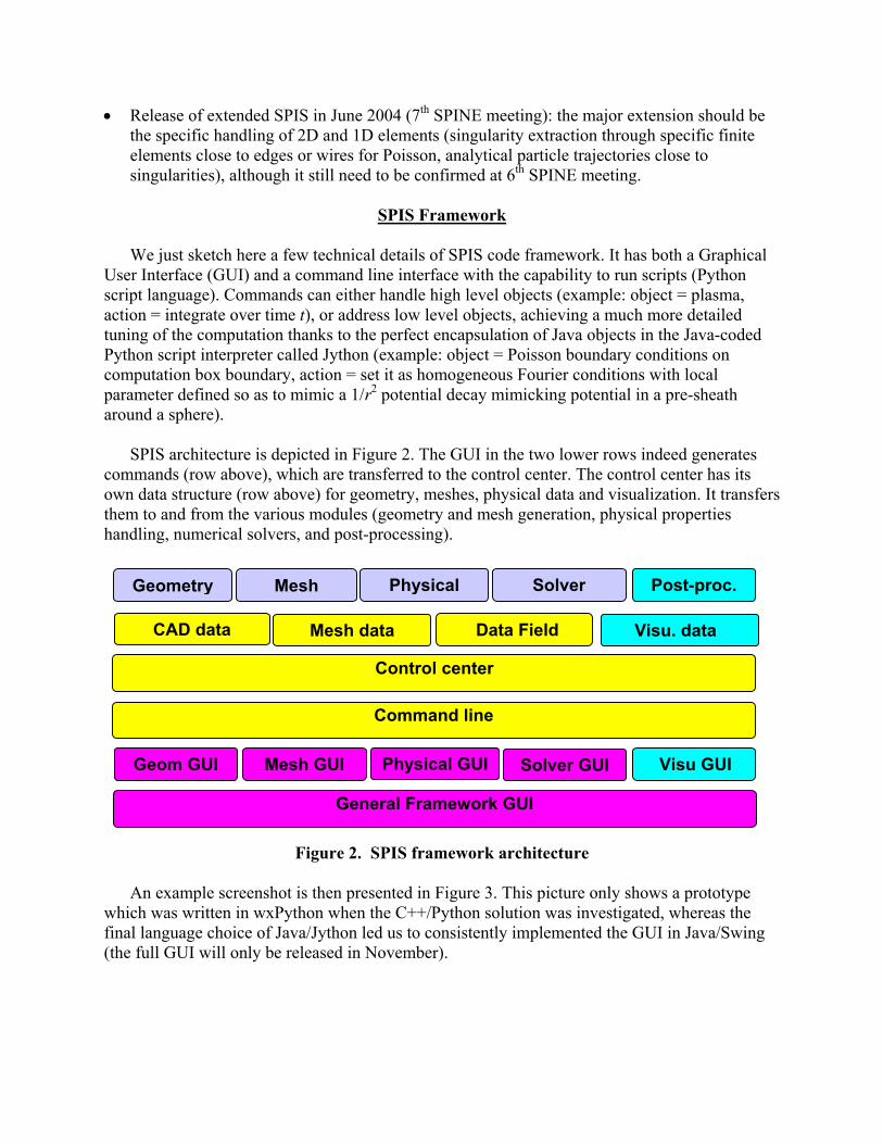
SPIS architecture is depicted in Figure 2. The GUI in the two lower rows indeed generates
commands (row above), which are transferred to the control center. The control center has its own data structure (row above) for geometry, meshes, physical data and visualization. It transfers them to and from the various modules (geometry and mesh generation, physical properties handling, numerical solvers, and post-processing).
Data Field
Command line
Visu. data Mesh data CAD data
General Framework GUI
Visu GUISolver GUIPhysical GUIMesh GUI Geom GUI
Mesh Geometry
Control center
SolverPhysical Post-proc.
Figure 2. SPIS framework architecture
An example screenshot is then presented in Figure 3. This picture only shows a prototype which was written in wxPython when the C++/Python solution was investigated, whereas the final language choice of Java/Jython led us to consistently implemented the GUI in Java/Swing (the full GUI will only be released in November).

and the VTK views The main window... Figure 3. Prototype screenshot in wxPython and VTK pop up windows (post-procressing)
An example of volume meshing with one of the two interfaced mesh generators (Tetgen) is
also reported in Figure 4. This second mesh generator offers volume meshing around 1D or 2D objects (infinitely thin arrays on the Fig. 4 plot) contrarily to the first interfaced mesh generator (GMSH). Figure 4. Example of volume meshing with Tetgen (supports thin objects, as the PVA here)
Modularity and Polymorphism of Numerical Routines
In their current development state, the main novelty in the numerical routines, as compared to existing codes, is their modularity. It can roughly be stated that we know how to do a software to

simulate plasma-spacecraft interactions. This statement is supported by the number of existing such codes, even though some solvers may of course be more or less efficient, accurate or stable. What we have to do here yet involves a significantly extra difficulty. We have to make it modular so as to incorporate very heterogeneous modules such as:
• Mesh: unstructured or structured • Dimension: 3D, 2D, 1D (+ axysymetric…) • Matter: kinetic (e.g. Particle-In-Cell, PIC), fluid, or global (Boltzman distribution) • (Electric) Field: stored as a field, or stored as a potential • Field or variable: centring (nodes/edges/surfaces/cells), scalar/vector… • Solvers: different versions • …
As briefly stated above, using OO languages greatly helps to reach that goal, hence the choice of Java. This is implemented through polymorphism, i.e. different versions of objects, which, although internally coded very differently, offer the same services to external requests. For example, a matter distribution object shall offer two basic services, “move” and “get moment,” whatever their internal representation, either kinetic (PIC), fluid or global. So, the basic tool to implement modularity is available in an OO code. This is yet far from doing the job. The real difficulty indeed lies in the number of different polymorphisms to be implemented (list above). Straightforwardly implementing the polymorphism recipe just described leads to an horrific implementation, such as the examples depicted in Figure 5. A new branching of the derivation tree is defined to implement each polymorphism. The number of derived classes is multiplied at each step. The resulting enormous amount of classes is very difficult to handle, support and modify. Development costs rise, while modularity is largely lost. So, the right way to ensure a good modularity is by uncoupling the polymorphisms, replacing class number multiplications by additions, as will be explained next.
Matter model
Global (Boltzman)Fluid (Euler…)Kinetic (PIC)
Field
Nodecentred
3D
On structured mesh On unstructured mesh
2D 1D 3D 2D 1D
Cellcentred …
Scalar Vector …
3D
On structured mesh On unstructured mesh
2D 1D 3D 2D 1D …
With electricfield
Withpotential …
Figure 5. Two examples of horrific implementation of multiple polymorphism (triangle
arrows represented different derived classes in these UML diagrams)
Before explaining this idea through a few examples, we present the overall SPIS conceptual class diagram in Figure 6. It will help understand the examples. In the UML graph of the figure

the arrows ended with a diamond represent the aggregation, or composition: the Simulation object on the right is composed of 1 Plasma object and 1 Spacecraft object, etc. The arrows ended with a triangle represent derivation or specialisation: a VolDistribution object can be either of a FluidDistribution version, a KineticPICDistribution or a GlobalDistribution. In the 1st case it will be composed of VolField objects (distribution moments), of 1 ParticleList object in the 2nd case, and simply a few global parameters in the 3rd case (not represented). The class names should be explicit enough for the reader to understand the chart.
Global Distribution
Global Flux
VolInteraction
PIC Flux
Particle ListPositionsVelocitiesWeightsTypeFlag, index
1 11 1
CircuitConnectivity
Integrate()GetPotential()
Fluid fluxSurfMesh
Geometry
Advance()CurrentDeposit()
0..n
1
0..n
1
Derives
Circuit FieldValues
Combine()1..n 11..n 1
VolDistributionDistribution functionPossibly moments
move()GetMoment()Combine()
VolFieldValuescentring
GetField()Combine()
VolMeshGeometry
PoissonSolve()Advance()ChargeDeposit()Gradient()Interpolate()
0..n
1
0..n
1
1..n
0..1
1..n
0..1
0..n
0..1
0..n
0..1
1
0..1
1
0..1
Plasma
Integrate()1
1..n0..n
Simulation
Integrate()
1
1
Spacecraft
DeriveCircuit()Integrate()MapSurfToCirc()MapCircToSurf()
11
11
1
0..1
1
0..1 1
SurfFieldValuesCentring
Combine()GetField()
0..n
1
0..n
1
Maps
SurfInteractionInteract()
Surface DistributionFlux distributionPossibly moments
GetMoment()Combine()
1..n
0..1
1..n
0..1
1
1
1
1
1
1..n0..n
Fluid Distribution
1..n1..n
KineticPIC Distribution
1 11 1
Figure 6. UML graph of SPIS conceptual class design. Each box is a class, the 2nd part of
the box contains attributes (i.e. data), the 3rd part operations (i.e. methods). Diamond arrows indicate composition, triangle arrows indicate specialization (i.e. derivation).
Figure 7 represents a top level design of the Volume Distribution class, and in particular how
its polymorphism can be uncoupled from others. As already written above, the three derived classes are PIC Volume Distribution, Fluid Volume Distribution, and Global Volume Distribution of Boltzmann type, one per column (class names are sometimes abbreviated but should remain explicit enough). The Move and Get Moment methods must be implemented for each of the classes derived from Volume Distribution. The coding of these methods is necessarily different for each derived type, kinetic, fluid, or global. The good design introduced above, i.e. the uncoupling of polymorphisms, consists in making the implementation of these methods independent of the other polymorphisms, e.g. the mesh type, space dimensionality, E field storage, etc. The arrows on the left hand side show how it works on some examples:
- The E.GetField(pl, E_Val) method of the E field object returns the electric field value at the
particle list positions whatever the specialization of E is, either stored as a potential (usual in electrostatics) or as an actual vector field (more common in electromagnetism). The

polymorphism of the vector field potential/vector is uncoupled from the volume distribution one, it is transparent when integrating particle trajectories. This was a very simple case.
- The pl.vm.Advance(pl,dx) method is basically a computation of particle trajectories
intersection with spacecraft and box boundaries. It is of course very dependant of the type of mesh (structured or unstructured…). But this is transparent for the particle method Move, which simply requires this computation from the generic Advance method of the volume mesh vm in which the particles are tracked, whatever the volume mesh type is.
There is indeed many more polymorphisms to uncouple in this routine than actually
emphasized by the arrows. Space dimension does not show in this routine whereas it might be omnipresent, if coded without care. This is true for the Advance method already discussed, since its actual implementation is dependant on the mesh type but of course also on space dimension. It is also the case for the trajectory integration, which is the core of that routine. It is crudely symbolized in this figure by ‘v = v + (E+vXB) dt; dx = v dt’, but the vectors (lists) x, v, etc. are dependant on space dimension. The relationship between x increment and v gets even more complex in case of non Cartesian geometry (e.g. axisymmetry). So, both the objects (x, v, etc.) and the operations between them must be invoked independently of their actual implementation (e.g. through a position_increment_from_velocity method here in Java (not represented in the figure), not by overloading the + operator as it could perhaps be done in C++ if sub-types are accurate enough).

Figure 7. Example of polymorphism: Volume Distribution
Thanks to this uncoupling the Move method can perform its main job, i.e. particle trajectory integration†, independently of the sub-types of the other objects. In the simple example of Figure 7, it is a basic first order scheme. If an improved scheme is to be implemented, as a leapfrog (magnetic force to be changed) or an higher order scheme, it can simply be done in the Move routine, independently of the mesh type, space dimension, E or B field storage, etc., which is very important to offer a good modularity.
As a final illustration of polymorphism uncoupling, let us list how different objects, which
might a priori depend on space dimension (and symmetries), were made as much as possible independent of space dimension (object in bold font could not escape an explicit dimension-dependant implementation):
† Things are not as simple as in the simplified illustration of Figure 7, since for example the integration time step can depend on the mesh (CFL-type conditions), which forces to transmit such information from the mesh to the integration routine (simply as a global maximum time step, or better a particle-dependent time step for sub-cycling)

• Volume or surface mesh:
• Data structure: explicit implementation • Solvers: partially dimension-specific: e.g. Poisson equation matrix writing is dimension-
specific, whereas its solving is not
• Vector table : explicit implementation, table of different dimension • Particle list: transparent, handled at vector table level • Volume or surface fields: transparent (a vector field in 3D is 3D table of 3 values):
• stored in 1D tables (may be recast in 3D/2D tables for structured solvers, but this is handled at mesh/solver level)
• Vector fields => handled at “vector table” level
• Volume or surface distributions: transparent:
• data: transparent, handled at particle list (PIC Distribution) or field level (Fluid Distribution)
• Solvers, main example of Move() (cf. Figure 7): • if PIC transparent • if fluid => transferred to mesh solver.
A last remark about object design has to do with efficiency. OO programming is very
interesting to design modular codes, but there is a cost associated with each object, a memory cost and certainly more important a computation time cost. In order to avoid these costs to impact significantly the overall performance, no “small objects” were defined, i.e. individual particles or mesh cells were not defined as objects. As visible on the examples above, only “large objects” were implemented, i.e. particle lists or cell lists. This allowed to maintain the extra computation load due to object handling to a very reasonable amount.
Conclusions
A new software dedicated to spacecraft plasma interaction modeling was presented. Its major originality is its openness. It is collaboratively developed within SPINE community, an open community of scientists and engineers studying spacecraft plasma interactions. In that purpose, the code is released under an open source form (sources distributed under GPL license). The code framework based on modern techniques (Java, Jython, Swing) and on open source pre-post/processing tools, and the object design of the solvers ensuring an efficient modularity were eventually presented.
The free access to this code should allow an important spreading in science and technology
teams, leading to an extensive testing and validation. The principle of open source collaborative development is to use the code, enhance it by adding extra modules, improving the existing ones,

or simply testing them, and then let the community profit by these improvements as a return. As shown by the interest for the code in Europe and worldwide, this positive dynamics is likely to be significantly enhanced after SPIS full release in spring 2004.

References
1. Roussel, J.-F, “Spacecraft Plasma Environment and Contamination Simulation Code:
Description and First Test,” Journal of Spacecraft and Rockets, Vol.35, No.2, p.205-211, 1998.
2. Neergaard, L. et al., ”Comparison of the NASCAP/GEO, SEE Interactive Charging
Handbook and NASCAP-2K Spacecraft Charging Codes,” 7th Spacecraft Charging Technology Conference,23-25 April 2001, ESTEC, The Netherlands, ESA SP-476, pp115-, 2001.
3. Mandell, M., “NASCAP-2K – An Overview,” this conference.
4. Forest, J., “Feedbacks On the PicUp3D Experience and the Open Source Strategy
Applied to a Spacecraft-Plasma Interaction Simulation Code,” this conference.
5. Thiebault, B., “Modeling Of The Photoelectron Sheath Around An Active Magnetospheric Spacecraft With Picup3d,” this conference.
Related Documents