DESIGN OF A BLOW OFF VALVE FOR TURBOCHARGED ENGINE APPLICATIONS MOHD FADHLI BIN MOHD NASIR A project report submitted in partial fulfillment of the requirements for the award of the Bachelor of Mechanical Engineering Faculty of Mechanical Engineering Universiti Malaysia Pahang NOVEMBER 2007

Welcome message from author
This document is posted to help you gain knowledge. Please leave a comment to let me know what you think about it! Share it to your friends and learn new things together.
Transcript

DESIGN OF A BLOW OFF VALVE FOR TURBOCHARGED
ENGINE APPLICATIONS
MOHD FADHLI BIN MOHD NASIR
A project report submitted in partial fulfillment of the
requirements for the award of the Bachelor of Mechanical Engineering
Faculty of Mechanical Engineering
Universiti Malaysia Pahang
NOVEMBER 2007

ABSTRACT
On a turbo engine, the Blow of Valve (BOV) is used to relieve the pressure
from the turbo output when the throttle is closed. Without the BO y, when the throttle
is closed the turbo is suddenly trying to pump air against a closed throttle plate. This
creates pressure spike in the turbo output hose and will send back the pressure to the
turbine and can damage the turbo engine. When the throttle is opened again, the
turbo has to spin up again, creating turbo lag. So, the present of the BOY will opened
when the throttle is closed and pressurized the pressure spike to the air to avoid those
phenomena. So, good flow of the air inside the BOV is important, the air will
smoothly pressurized to the atmosphere if there is no back pressure inside the
system. Computer aided design (CAD) and computational fluid dynamic (CFD)
software were used as a tool for the design. This design is the improvement of the
aftermarket design. The piston surface, size of vent, inlet ports, outlet ports, and also
spring plays the role in the BO y. The design analyzed using CFD so can see the flow
trajectories of the air inside the BOy.
V

ABSTRAK
Di dalain sistem turbo, Blow off Valve (BOV) digunakan untuk melepaskan
tekanan udara yang terkandung di dalam sistem apabila pendikit tertutup. Tanpa
BOy, tekanan udara tadi akan tetap memben tekanan untuk keluar dari sistem. mi
akan menyebabkan terjadinye tekanan didalam sistem bertambah dan tekanan udara
mi akan mengalir semula ke turbin dan akan menyebabkan kerosakan berlaku pada
enjm. Apabila pendikit terbuka semula, turbin akan berputar semula dan mi akan
menyebabkan phenomena "turbo lag". Dengan kehadiran BO y, tekanan udara
didalam sistem tadi boleh dilepaskan ke udara ketika pendikit tertutup. Jadi,
pengaliran udara adalah sangat penting untuk memastikan supaya tiada tekanan
udara yang mengalir semula ke dalam sistem. Computer aided design (CAD) dan
computational fluid dynamic (CFD) adalah perisian yang digunakan didalam
penyelidikan mi. Dengan penambahbaikan daripada model-model BOV yang telah
sedia ada di pasaran, maka terciptalah model mi. Bahagian seperti pennukaan piston,
saiz alur didalam BOy, tempat masuknya udara kedalam BOy, tempat keluarnya
udara dari dalam BOV dan juga spring masing-masing memainkan peranan didalam
sesuatu BOy. Untuk melihat pengaliran udara di dalam BOy, CFD digunakan.
vi
TABLE OF CONTENTS
CHAPTER TITLE PAGE
DECLARATION
DEDICATION
ACKNOWLEDGEMENTS iv
ABSTRACT v
TABLE OF CONTENTS vii
LIST OF TABLES xi
LIST OF FIGURES xii
LIST OF APENDICES xv
1 INTRODUCTION 1
1.1 Background 1
1.2 Problem Statement 2
1.3 Objective of the Project 3
1.4 Scope of Project 3
2 LITERATURE REVIEW 4
2.1 Turbochargers 4
2.2 Comparisons between Turbochargmg
and Supercharging 7
vii

viii
2.3 Turbochargerd Components 10
2.3.1 Pressure Release Valve 10
2.3.2 Intercooler 10
2.3.3 Wastegate 11
2.3.4 Turbocharger Unit 12
2.4 Pressure Release Valve 13
2.4.1 Compressor Bypass Valve (CBV) 13
2.4.2 Blow off Valve (BOV) 14
2.4.2.1 How Blow off Valve Works 16
2.4.2.2 APS High Volume Twin
Vent Blow of Valve 18
2.4.2.3 Universal HKS Super
Sequential BOV 21
2.4.2.4 Greddy Type "Rs"
Blow Off Valve 22
3 METHODOLOGY 24
3.1 Specification Definition 24
3.1.1 Collecting Data and Literature Review 24
3.1.2 Requirements 25
3.1.3 Engineering Specification 25
3.2 Reverse Engineering 26
3.2.1 APS Type 26
3.2.2 SSQV (Super Sequential Blow off
Valve) Type - Monza 28
3.2.3 SSQV(Super Sequential Blow off
Valve Type - Taiwan 29.
3.3 Hooke's Law Experiment 31
3.4 CFD Simulation of the Aftermarket
Blow off Valve 32
3.4.1 APS Type 34
3.4.2 SSQV (Super Sequential Blow off
Valve) Type - Monza 35

lx
4
3.4.3 SSQV (Super Sequential Blow off
Valve) Type - Taiwan 36
3.5 Conceptual Design 37
3.5.1 General Concept 37
3.5.2 Make Concept Decision 38
3.6 Product Development 38
3.6.1 Engineering Drawing 38
3.6.2 Own Design Blow off Valve 39
3.6.3 Operation of the Designed BOV 39
3.6.4 CID Simulation of the Designed BOV 42
RESULTS AND DISCUSSION 43
4.1 Introduction 43 4.2 Hooke's Law Experiment 43
4.2.1 APS Type Spring 44
4.2.2 Super Sequential Blow off
Valve Type's Spring (Monza) 45
4.2.3 Super Sequential Blow off
Valve Type's Spring (Taiwan) 46
4.2.4 Discussion of the Hooke's Law
Experiment 47
4.3 CFD CosmosFioworks Analysis Result 47
4.3.1 Variable Opening of the Valve 48
4.3.1.1 Moderate Opened Valve 48
4.3.1.2 Fully Opened Valve 50
4.3.2 Variable of Inlet Pressure 52
4.3.2.1 Inlet Pressure - lSOkPa 52
4.3.2.2 Inlet Pressure - 200kPa 54
4.3 The Own Design Analysis 56
CONCLUSIONS AND RECOMMENDATIONS 58
5.1 Conclusions 58

5.2 Recommendations 59
REFERENCES 60
APPENDICES A-B 61
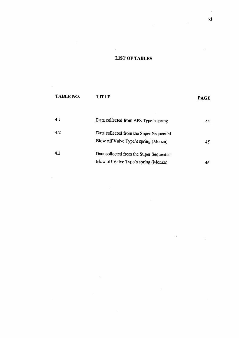
LIST OF TABLES
TABLE NO. TITLE PAGE
4.1 Data collected from APS Type's spring 44
4.2 Data collected from the Super Sequential
Blow off Valve Type's spring (Monza) 45
4.3 Data collected from the Super Sequential
Blow off Valve Type's spring (Monza) 46
xi

LIST OF FIGURES
FIGURES NO. TITLE
PAGE
2.1 Cut away view of turbocharger 5
2.2 Parts of the turbocharger 6
2.3 Turbocharger principle of operation 7
2.4 Supercharger 9
2.5 Turbocharger 9
2.6 Turbocharger and its component 11
2.7 Cut away view of a wastegate 12
2.8 Bosch Style CBV 14
2.9 Blow off valve in turbocharged system 16
2.10 BOV condition when the throttle is close 17
2.11 BOV condition when the throttle is open 18
2.12 Ports closed 19
2.13 Primary port open 20
2.14 Bothports open 20
2.15 APS high volume twin vent blow off valve 21
2.16 The HKS Super Sequential Blow off Valve (SSQV) 22
2.17 Greddy Type's "RS" Blow off Valve 23
xii

xli'
3.1 APS Type Blow off Valve 26
3.2 APS BOV condition when port closed 27
3.3 All APS BOV ports fully closed 27
3.4 Super Sequential Blow off Valve Type (Monza) 28
3.5 SSQV Monza first stage 28
3.6 SSQV Monza valve is fully opened (second stage) 29
3.7 Super Sequential Blow off Valve Type (Taiwan) 29
3.8 SSQV Taiwan's port closed 30
3.9 SSQV Taiwan's port fully opened 31
3.10 Simulation steps for the simulation 33
3.11 Example of analysis using CFD on APS Type BOV 34
3.12 Example of analysis using CFD on SSQV Monza 35
3.13 Example of analysis using CFD on SSQV Taiwan 36
3.14 Own design BOV 39
3.15 Own design BOV condition when both ports closed 40
3.16 Own design BOV condition when primary ports
partially opened 40
3.17 Own design BOV condition when both ports opened 41
3.18 Example of analysis using CFD on own design BOV 42
4.1 Graph force vs displacement for APS Type's spring 44
4.2 Graph force vs displacement for Super Sequential Blow
off Valve Type (Monza) 45
4.3 Graph force vs displacement for Super Sequential Blow
off Valve Type (Taiwan) 46
4.4 Simulation flow trajectories of APS Type -
Moderate Opened (250kPa) 48
xlv
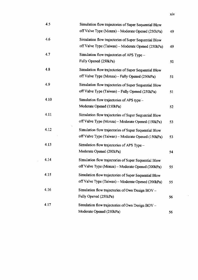
4.5 Simulation flow trajectories of Super Sequential Blow
off Valve Type (Monza) - Moderate Opened (250kPa) 49
4.6 Simulation flow trajectories of Super Sequential Blow
off Valve Type (Taiwan) - Moderate Opened (2500a) 49
4.7 Simulation flow trajectories of APS Type -
Fully Opened (2500a) 50
4.8 Simulation flow trajectories of Super Sequential Blow
off Valve Type (Monza) - Fully Opened (2500a) 51
4.9 Simulation flow trajectories of Super Sequential Blow
off Valve Type (Taiwan) - Fully Opened (2500a) 51
4.10 Simulation flow trajectories of APS type
Moderate Opened (150kPa) 52
4.11 Simulation flow trajectories of Super Sequential Blow
off Valve Type (Monza) - Moderate Opened (150kPa) 53
4.12 Simulation flow trajectories of Super Sequential Blow
off Valve Type (Taiwan) - Moderate Opened (150kPa) 53
4.13 Simulation flow trajectories of APS Type-
Moderate Opened (2000a) 54
4.14 Simulation flow trajectories of Super Sequential Blow
off Valve Type (Monza) - Moderate Opened (2000a) 55
4.15 Simulation flow trajectories of Super Sequential Blow
off Valve Type (Taiwan) - Moderate Opened (200kPa) 55
4.16 Simulation flow trajectories of Own Design BOV -
Fully Opened (250kPa) 56
4.17 Simulation flow trajectories of Own Design BOV -
Moderate Opened (2500a) 56

LIST OF APPENDICES
APPENDIX TITLE PAGE
A Thesis Gantt Cahart 61
B CFD Analysis 62
xv

CHAPTER 1
INTRODUCTION
1.1 Background
On a turbo engine, the Blow of Valve (BOV) is used to relieve the pressure
from the turbo output when the throttle is closed. These valves are only used on
engines with the blow-through turbo setup.
While in boost, the valve remains closed and the turbo pumps air into the
engine normally. Without the BOy, when the throttle is closed the turbo is suddenly
hying to pump air against a closed throttle plate. This creates a pressure spike in the
turbo output hose and sends a pressure "wave" crashing back and forth between the
throttle plate and the turbo compressor blades. The pressure spike quickly slows
down the turbo and the pressure wave can actually damage the turbo.
When the throttle is opened again, the turbo has to spin up again, creating
turbo lag. If a BOV is present, the BOV will open as soon as the throttle is closed,
releasing the pressure spike into the air box and avoiding the pressure wave phenomena.
2
This study was carried out to get the comparison between the numbers of
blow off valve type available in the market for the suitable performance for the
turbocharged engine. It will include project definition, the engineering development,
concept/idea generation and come out with own blow off valve design.
1.2 Problem Statement
When people talk about race cars or high-performance sports cars, the topic
of turbochargers usually comes up. A turbo can significantly boost an engine's
horsepower without significantly increasing its weight. But there is some problem
will occur.
When the throttle body closes - the stream of pressurized air created by the
turbocharger is now cut off from the inlet manifold. The only way it can escape is
back up the intake stream, surging into the turbo compressor. This reversal of intake
charge pulse can put additional strain on the turbo components, as well as reducing
the compressor wheel's rotational velocity. This means that the turbo will take longer
to spool up when the throttle is opened again.
So, there is a valve placed before the throttle body cures this problem by
allowing the pressurized charge to escape the intake system, keeping the compressor
spinning and reducing turbo lag. This creates a very distinctive sound desired by
many who own turbocharged sports cars. Some blow off valves is sold with trumpet
shaped exits that amplify the "Psshlihh" sound; these designs are normally marketed
towards the keen boy racer. So there are many types of blow off valve available in
the market.
Therefore the need to study the concept, designs and components of the
Pressurize release system present in the turbocharged engine is significant. Study
3
also will be done base on reverse engineering on a number of a different blow off
valve type available in the market. The CAD modeling and Flow Simulation also
will be done to complete this study.
1.3 Objective Of The Project
The objectives of the project are:
i. Study the existing blow off valve designs and components.
ii. Design a pressure relief valve for turbocharged engine applications.
1.4 Scope Of Project
The scopes of this project include three main parts:
i. Study the concepts, designs and component of the pressure release
system present in the turbocharged engines.
ii. Reverse engineering on the number of different blow off valve type
available in the market.
ill. CAD modeling and Flow simulation using SolidWorks 2005 and
COSMOS FloWorks 2005/PE
CHAPTER 2
LITERATURE REVIEW
2.1 Turbocharger
A turbocharger is a dynamic compressor, in which air or gas is compressed
by -the mechanical action of impellers, vane rotors which are spun using the kinetic
movement of air, imparting velocity and pressure to the flowing medium. A
turbocharger is basically a device that uses exhaust gasses produced by the engine to
blow air back into the engine as shown in Figure 2.1. The additional air is
supplemented with fuel by the ECU (engine control unit). This causes the engine to
produce much more power since it is being supplied with more air and fuel than it
possibly could without it. With this setup, the most air pressure that can enter the
combustion chamber of the engine is a bit less than the current atmospheric
pressure. With the turbo, air is being blown into the chamber with positive pressure
so that much more air and fuel can enter. A typical turbocharged engine will
generate 7 to 10 psi of maximum positive pressure, or "boost".
4
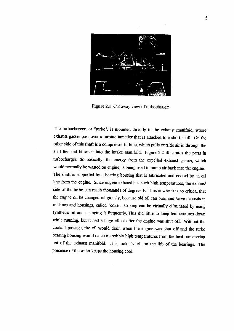
Figure 2.1: Cut away view of turbocharger
The turbocharger, or "turbo", is mounted directly to the exhaust manifold, where
exhaust gasses pass over a turbine impeller that is attached to a short shaft. On the
other side of this shaft is a compressor turbine, which pulls outside air in through the
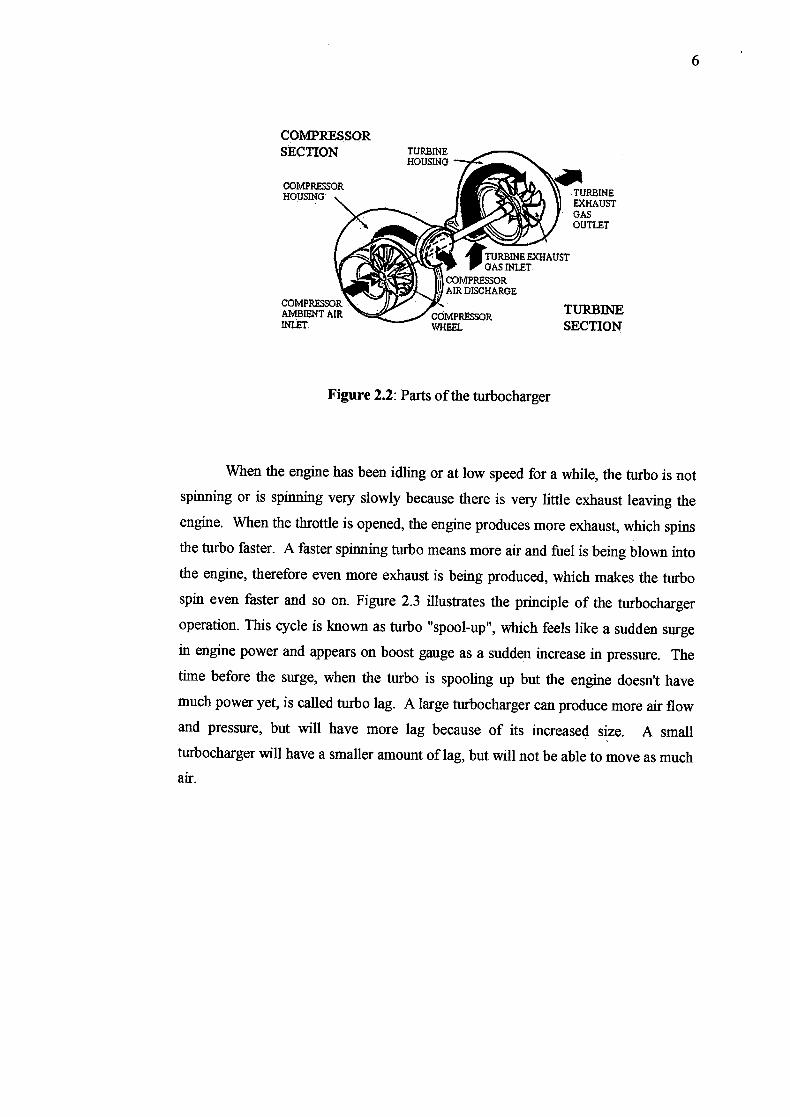
air filter and blows it into the intake manifold. Figure 2.2 illustrates the parts in
turbocharger. So basically, the energy from the expelled exhaust gasses, which
would normally be wasted on engine, is being used to pump air back into the engine.
The shaft is supported by a bearing housing that is lubricated and cooled by an oil
line from the engine. Since engine exhaust has such high temperatures, the exhaust
side of the turbo can reach thousands of degrees F. This is why it is so critical that
the engine oil be changed religiously, because old oil can bum and leave deposits in
oil lines and housings, called "coke". Coking can be virtually eliminated by using
synthetic oil and changing it frequently. This did little to keep temperatures down
while running, but it had a huge effect after the engine was shut off. Without the
coolant passage, the oil would drain when the engine was shut off and the turbo
bearing housing would reach incredibly high temperatures from the heat transferring
out of the exhaust manifold. This took its toll on the life of the bearings. The
presence of the water keeps the housing cool.
5
COMPRESSORTURBINE SECTION
COMPRESSORTURBINEHOUSING EXHAUST
GAS UTLET
- TURBINE EXHAUST GAS INLET
COMPRESSOR AIR DISCHARGE
AMBIENT MR COMPRESSOR
Figure 2.2: Parts of the turbocharger
When the engine has been idling or at low speed for a while, the turbo is not
spinning or is spinning very slowly because there is very little exhaust leaving the
engine. When the throttle is opened, the engine produces more exhaust, which spins
the turbo faster. A faster spinning turbo means more air and fuel is being blown into
the engine, therefore even more exhaust is being produced, which makes the turbo
spin even faster and so on. Figure 2.3 illustrates the principle of the turbocharger
operation. This cycle is known as turbo "spool-up", which feels like a sudden surge
in engine power and appears on boost gauge as a sudden increase in pressure. The
time before the surge, when the turbo is spooling up but the engine doesn't have
much power yet, is called turbo lag. A large turbocharger can produce more air flow
and pressure, but will have more lag because of its increased size. A small
turbocharger will have a smaller amount of lag, but will not be able to move as much
air.

CHARGE AIR COOLER
ENGINE COMPRES ,uziiôw CYLINDER TURBOCHARGER
OIL INLET
TURBINE WHEEL COMPRESSOR
EXHAUST AMBIENT GAS• AIR INLET DISCHARGE
COMPRESSOR WHEEL
Oil. OUTLET WASTEGATE
Figure 2.3: Turbocharger Principle of Operation
2.2 Comparisons between Turbocharging and Supercharging
The term supercharging technically refers to any pump that forces air into an
engine - but in common usage, it refers to pumps that are driven directly by the
engine as opposed to turbochargers that are driven by the pressure of the exhaust
gasses.
Positive displacement superchargers may absorb as much as a third of the
total crankshaft power of the engine, and in many applications are less efficient than
turbochargers. In applications where engine response and power is more important
than any other consideration, such as top-fuel dragsters and vehicles used in tractor
pulling competitions, positive displacement superchargers are extremely common.
Superchargers are generally the reason why tuned engines have a distinct high-
pitched whine upon acceleration.
There are three main styles of supercharger for automotive use:
• Centrifugal turbochargers (Figure 2.4) - driven from exhaust gasses.
• Centrifugal superchargers (Figure 2.5) - driven directly by the engine via a
belt-drive.
7
8
• Positive displacement pumps (such as the Roots and the Lyshoim (Whipple)
blowers).
The thermal efficiency, or fraction of the fuel/air energy that is converted to
output power, is less with a mechanically driven supercharger than with a
turbocharger, because turbochargers are using energy from the exhaust gases that
would normally be wasted. For this reason, both the economy and the power of a
turbocharged engine are usually better than with superchargers.
The main advantage of an engine with a mechanically driven supercharger is
better throttle response. With the latest Turbo Charging technology, throttle response
on turbocharged cars is nearly as good as with mechanical powered superchargers.
Especially considering that the vast majority of mechanically driven superchargers
are now driven off clutched pulleys, much like an air compressor.
Keeping the air that enters the engine cool is an important part of the design of
both superchargers and turbochargers. Compressing air makes it hotter so it is
common to use a small radiator called an intercooler between the pump and the
engine to reduce the temperature of the air.
Turbochargers also suffer from so-called turbo-lag in which initial acceleration
from low revolution per minute (RPM) is limited by the lack of sufficient exhaust
gas pressure. Once engine RPM is sufficient to start the turbo spinning, there is a
rapid increase in power as higher turbo boost causes more exhaust gas production -
which spins the turbo yet faster, leading to a belated "surge" of acceleration. This
makes the maintenance of smoothly increasing RPM far harder with turbochargers
than with belt-driven superchargers which apply boost in direct proportion to the
engine RPM.
Turbo-lag is often confused with the term Turbo-spool. Turbo Lag refers to how
long it takes to spool the turbo when there is sufficient engine speed to create boost.
This is greatly affected by the specifications of the turbocharger. If the turbocharger

is too large for the power band that is desired, needless time will be wasted trying to
spool the turbocharger.
Figure 2.4: Supercharger
Figure 2.5: Turbocharger

10
2.3 Turbocharger Components
Turbocharger system has many components such as pressure release valve,
intercooler, wastegate and a turbocharger unit itself. Each component has its own
function and specification.
2.3.1 Pressure Valve Release
There are two types of pressure release valve. Compressor bypass valve and
blow off valve. Commonly CBV is found on many original engine manufactured
turbo engine while BOV in advanced turbocharged engine. For the further
information please refer Section 2.4.
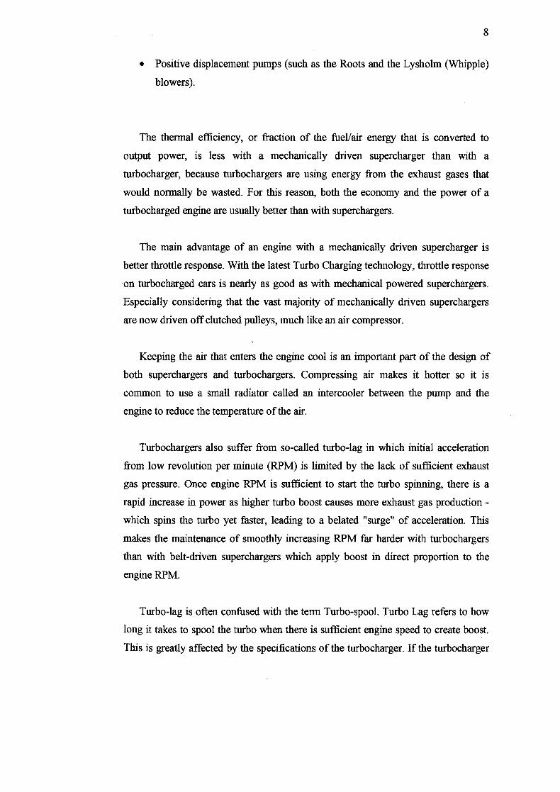
2.3.2 Intercooler
An intercooler is a heat exchanger as shown in Figure 2.6, positioned
between the turbocharger and the intake manifold. It is a device used on
turbocharged and supercharged internal combustion engines to improve the
volumetric efficiency, increase the amount of charge in the engine, and lower charge
air temperature thereby increasing power and reliability. The intake may cooled by
the ambient air, engine jacket water, iced water, low temperature liquid as cooling
medium.
Intercooler could reduce the intake charge temperature to the cooling medium
without any drop in pressure while reach 100% efficiency. But the perfect (100%
11
efficient) is not possible in this actual world because of there will be a pressure drop
through the intercooler and it is not possible to lower the charge temperature to that
cooling medium temperature. The cooling medium and intercooler design averagely
available at 70% to 75% efficiency in common.
Figure 2.6: Intercooler and its components
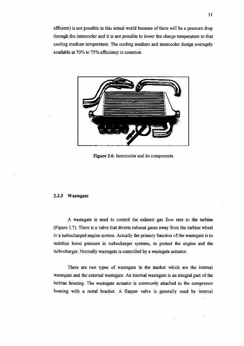
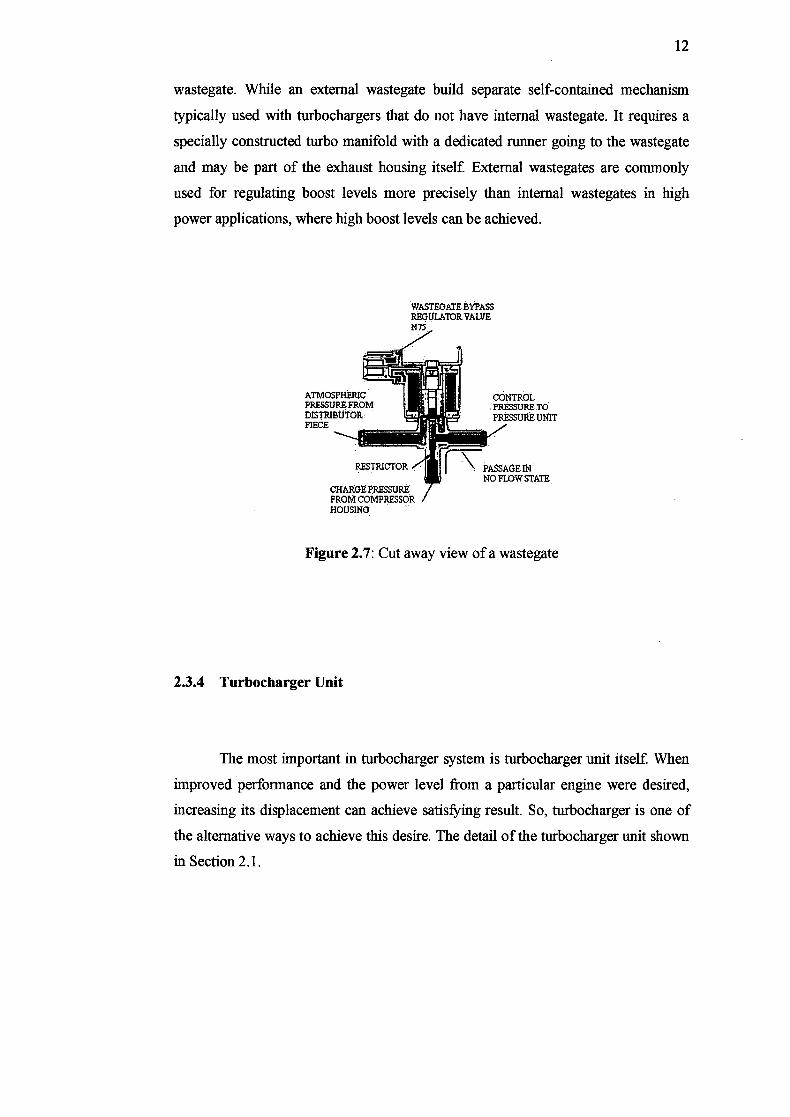
2.3.3 Wastegate
A wastegate is used to control the exhaust gas flow rate to the turbine
(Figure 2.7). There is a valve that diverts exhaust gases away from the turbine wheel
in a turbocharged engine system. Actually the primary function of the wastegate is to
stabilize boost pressure in turbocharger systems, to protect the engine and the
turbocharger. Normally wastegate is controlled by a wastegate actuator.
There are two types of wastegate in the market which are the internal
wastegate and the external wastegate. An internal wastegate is an integral part of the
turbine housing. The wastegate actuator is commonly attached to the compressor
housing with a metal bracket. A flapper valve is generally used by internal
12
wastegate. While an external wastegate build separate self-contained mechanism
typically used with turbochargers that do not have internal wastegate. It requires a
specially constructed turbo manifold with a dedicated runner going to the wastegate
and may be part of the exhaust housing itself. External wastegates are commonly
used for regulating boost levels more precisely than internal wastegates in high
power applications, where high boost levels can be achieved.
WASTEGATE BYPASS REGULATOR VALVE N75
ATMOSPHERIC coN ROL PRESSURE FROM PRESSURE TO DISTRIBUTOR. PRESSURE UNIT PIECE
RESTRICTOR PASSAGE IN NO FLOW STATE
CHARGE PRESSURE FROM COMPRESSOR HOUSING,
Figure 2.7: Cut away view of a wastegate
2.3.4 Turbocharger Unit
The most important in turbocharger system is turbocharger unit itself When
improved performance and the power level from a particular engine were desired,
increasing its displacement can achieve satisfying result. So, turbocharger is one of
the alternative ways to achieve this desire. The detail of the turbocharger unit shown
in Section 2.1.
Related Documents