POUR L'OBTENTION DU GRADE DE DOCTEUR ÈS SCIENCES acceptée sur proposition du jury: Prof. M.-O. Hongler, président du jury Prof. Y. Perriard, directeur de thèse Prof. R. Clavel, rapporteur Dr C. Peclat, rapporteur Prof. C. Stieger, rapporteur Design Methodology and Innovative Device Concept for Acoustic Hearing Implants THÈSE N O 4946 (2011) ÉCOLE POLYTECHNIQUE FÉDÉRALE DE LAUSANNE PRÉSENTÉE LE 18 FÉVRIER 2011 À LA FACULTÉ SCIENCES ET TECHNIQUES DE L'INGÉNIEUR LABORATOIRE D'ACTIONNEURS INTÉGRÉS PROGRAMME DOCTORAL EN SYSTÈMES DE PRODUCTION ET ROBOTIQUE Suisse 2011 PAR Hans BERNHARD

Welcome message from author
This document is posted to help you gain knowledge. Please leave a comment to let me know what you think about it! Share it to your friends and learn new things together.
Transcript

POUR L'OBTENTION DU GRADE DE DOCTEUR ÈS SCIENCES
acceptée sur proposition du jury:
Prof. M.-O. Hongler, président du juryProf. Y. Perriard, directeur de thèse
Prof. R. Clavel, rapporteur Dr C. Peclat, rapporteur
Prof. C. Stieger, rapporteur
Design Methodology and Innovative Device Concept for Acoustic Hearing Implants
THÈSE NO 4946 (2011)
ÉCOLE POLYTECHNIQUE FÉDÉRALE DE LAUSANNE
PRÉSENTÉE LE 18 FÉVRIER 2011
À LA FACULTÉ SCIENCES ET TECHNIQUES DE L'INGÉNIEUR
LABORATOIRE D'ACTIONNEURS INTÉGRÉS
PROGRAMME DOCTORAL EN SYSTÈMES DE PRODUCTION ET ROBOTIQUE
Suisse2011
PAR
Hans BERNHARD


Abstract
Nowadays, hearing impaired people can be treated with a multitude of different devices and surgical interventions that are selected in function of the type and degree of hearing loss of the patient. These known therapies cover the major part of possible hearing losses except severe to profound mixed hearing loss. The present thesis results from an industrial project that aims to develop a dedicated hearing therapy that treats this kind of hearing loss based on direct acoustic cochlear stimulation (DACS). A semi-implantable investigational hearing device is used in a clinical trial with four patients to validate this novel therapy approach. The development of this investigational hearing implant presents a considerable challenge due to the numerous medical and engineering aspects that have to be considered. The conceptual design process is therefore of central importance because it incorporates all the relevant aspects and defines the future device characteristics and performances. Fundamental design aspects that are not considered at this early design stage can only be implemented with difficulties and increased efforts later on. This is the motivation to develop within the scope of this thesis a conceptual design methodology that supports and facilitates this essential design phase. A conceptual design methodology for acoustic hearing implants is therefore presented at the example of the DACS investigational device. The methodology consists of a four-step-procedure and a system diagram tool. The four steps of the procedure are:
Step 1: determination and analysis of the human body functions that shall be emulated by the system
Step 2: determination of the preliminary system architecture Step 3: determination of the user and system requirements Step 4: conceptual design
The system diagram tool guides the engineer through all four steps and helps visualizing and structuring the system environments, functions, interfaces and, most important, all interactions between the system elements and environments. The diagram drawing rules ensure that all requirements coming from the environments are correctly linked with the concerned system functions and therefore ensure that the system meets all these requirements. Finally, the system diagram is a valuable tool for the conceptual design step. Because of the clearly represented system elements and interactions, it supports the development of integrated solutions. The output of the presented methodology is a design concept that cannot be directly quantified to assess the benefit of the methodology. Only once the resulting device is
successfully verified against the system requirements and validated against the user requirements, it can be concluded that the underlying concept is adequate. The outcome of the clinical study shows that the four implanted patients benefit all from the DACS device, which is therefore well suited to treat severe to profound mixed hearing loss. This confirms that device meets the user requirements and implies that conceptual design methodology is adequate. The realized investigational device consists of an externally worn audio processor, a percutaneous connector, and an implantable actuator. The hermetically sealed balanced armature actuator provides a maximal equivalent sound pressure level of 125 dB over the frequency range between 100 Hz and 10’000 Hz with a limited 1-mW power supply. A lumped parameter model of the actuator dynamics and a finite element model of the electro-mechanic actuator are used for the detailed actuator design.
Key Words Conceptual design methodology, system diagram, integrated solution, implantable hearing system, mixed hearing loss, balanced armature actuator, hermetically sealed transducer
Résumé
Aujourd’hui, des personnes malentendantes peuvent profiter de nombreux types d’appareils et d’interventions chirurgicales, qui sont choisis en fonction du type et du degré de la surdité du patient. Ces thérapies connues couvrent la majorité des surdités possibles à l’exception de la surdité mixte de sévère à grave. Cette thèse résulte d’un projet industriel, qui a comme but le développement d’une thérapie appropriée pour traiter ce type de surdité, basée sur la stimulation acoustique directe de la cochlée (DACS). Un appareil acoustique semi-implantable est utilisé pour valider cette nouvelle approche dans une étude clinique avec quatre patients. Le développement de l’appareil acoustique d’essai est un défi considérable parce que de nombreux aspects médicaux et techniques doivent être considérés. Voilà pourquoi le processus de design conceptuel est d’une importance centrale parce qu’il incorpore tous les aspects fondamentaux et définif les futures caractéristiques et performances de l’appareil. Des aspects de design fondamentaux, qui ne sont pas considérés dès le début de l’étude, ne peuvent qu’être difficilement implémentés et causent des efforts plus importants par la suite. C’est la motivation pour développer dans le cadre de cette thèse une méthode de design conceptuel qui assiste et facilite cette phase de design essentielle. Une méthode de design conceptuel pour des implants auditifs acoustiques est donc présentée avec l’exemple de l’appareil d’essai DACS. La méthode est constituée d’une procédure en quatre étapes et d’un outil pour la représentation graphique du système. Les quatre étapes de la procédure sont :
Pas 1 : détermination et analyse des fonctions corporelles humaines qui doivent être émulées par le système
Pas 2 : détermination de l’architecture préliminaire du système Pas 3 : détermination des exigences de l’utilisateur et du système Pas 4 : design conceptuel
L’outil pour la représentation graphique du système guide l’ingénieur à travers les quatre étapes et aide à visualiser et structurer les environnements du système, ses fonctions, ses interfaces et, le plus important, toutes les interactions entre les éléments du système et les environnements. Les règles de la représentation graphique assurent que toutes les exigences imposées par les environnements sont correctement attribuées aux éléments concernés du système. Cela assure que le système remplit toutes les exigences. Finalement, la représentation graphique du système est aussi un outil valable pour le design conceptuel. Grâce à la représentation explicite des éléments du système et les
interactions correspondantes, elle assiste et permet le développement de solutions intégrales. Le résultat de la méthode présentée est un concept de design qui ne peut pas être directement quantifié pour vérifier le bénéfice de la méthode. Ce n’est qu’après vérification par rapport aux exigences du système et après validation par rapport aux exigences de l’utilisateur de l’appareil résultant, qu’il est possible de conclure que le design conceptuel est adéquat. Les résultats de l’étude clinique montrent que les quatre patients profitent de l’appareil DACS, qui est bien adapté pour traiter la surdité mixte de sévère à grave. Cela confirme que l’appareil remplit les exigences de l’utilisateur et implique que la méthode de design conceptuel est adéquate. L’appareil d’essai réalisé est constitué d’un processeur audio externe, d’un connecteur percutané et d’un actionneur implantable. L’actionneur à armature balancée, qui est hermétiquement encapsulé, génère une pression sonore équivalente de 125 dB dans une gamme de fréquence de 100 Hz à 10'000 Hz avec une alimentation limitée à 1 mW. Un schéma équivalent mécanique-électrique est utilisé pour simuler les caractéristiques dynamiques de l’actionneur. La conversion électromagnétique est simulée avec un modèle à éléments finis.
Mots clés Méthode de design conceptuel, diagramme de système, solution intégrée, implant auditif, surdité mixte, actionneur à armature balancée, transducteur avec encapsulation hermétique

Acknowledgements
The DACS investigational device project counted numerous people and companies that were involved during the whole project duration of about four years. All of them have contributed to the successful outcome. Even if this thesis was more or less developed independently in parallel to the main project activities, it would not have been possible to complete it without the completion of the main project. Therefore I would like to express my gratitude to all people that have contributed to this project. Special thank goes to Prof. Dr. Y. Perriard and Dr. M. Markovic for facilitating this thesis and for helping me through difficult working phases. I would like to thank Dr. C. Péclat for supporting this work from the very beginning and for giving me the necessary freedom at my workplace. Thanks also to all my working colleagues for their outstanding contribution to the project. I would like to thank Dr. M. Haller for the very pleasant and fruitful collaboration during the whole project duration. I am deeply grateful for the very productive and pleasant collaboration with the project team from the Cochlear Technology Center. I would like to express my gratitude to P. Steffen for his contribution regarding the implementation of one of the key fabrication processes and being available even on Christmas Eve to complete the first batch of implantable grade actuators in due time. In the end I would like to thank Prof. Dr. R. Häusler and Prof. Dr. C. Stieger. Both played key roles in respect of the project success and allowed me very interesting insights into the clinical aspects of the project.


Table of Contents 1 Introduction .............................................................................................................. 1
1.1 Motivation ........................................................................................................... 1 1.2 Anatomy and Physiology of the Ear.................................................................... 1
1.2.1 Overview .................................................................................................. 2 1.2.2 Outer Ear.................................................................................................. 2 1.2.3 Middle Ear ................................................................................................ 3 1.2.4 Inner Ear................................................................................................... 5
1.3 Hearing Disorders ............................................................................................... 6 1.3.1 Types of Hearing Loss ............................................................................. 6 1.3.2 Assessment of Hearing Disorder – The Audiogram................................. 6
1.4 Hearing Therapies .............................................................................................. 8 1.4.1 Overview .................................................................................................. 8 1.4.2 Hearing Aids............................................................................................. 9 1.4.3 Middle Ear Surgery................................................................................... 9 1.4.4 Bone anchored hearing aids .................................................................. 10 1.4.5 Cochlear Implants .................................................................................. 11 1.4.6 Middle Ear Implants................................................................................ 11
1.5 DACS Therapy Concept ................................................................................... 12 1.5.1 State of the Art ....................................................................................... 12 1.5.2 The DACS Approach.............................................................................. 13
1.6 About this Work................................................................................................. 14 1.6.1 The Specific Challenges......................................................................... 14 1.6.2 Proposed Approach................................................................................ 15 1.6.3 Thesis Outline ........................................................................................ 16
2 Conceptual Design Methodology for Acoustic Hearing Implants ........................... 19 2.1 Introduction ....................................................................................................... 19 2.2 State of the Art .................................................................................................. 19
2.2.1 Design Methodology............................................................................... 19 2.2.2 Analysis of Existing Acoustic Hearing Implants...................................... 20 2.2.3 Summary of Extracted Design Methodology Requirements................... 28
2.3 Proposed Methodology..................................................................................... 28 2.3.1 Introduction............................................................................................. 28 2.3.2 Definition of Terms and Corresponding Diagram Symbols .................... 30 2.3.3 Definition of Diagram Drawing Rules ..................................................... 34 2.3.4 Step 1: Determination and Analysis of Human Body Functions that Shall Be Emulated by the System................................................................................... 37 2.3.5 Step 2: Determination of Preliminary System Architecture .................... 42 2.3.6 Step 3: Determination User and System Requirements......................... 43 2.3.7 Step 4: Conceptual Design..................................................................... 50
2.4 Summary and Discussion ................................................................................. 56
3 Investigational Device............................................................................................ 57 3.1 Introduction and Overview................................................................................ 57 3.2 Actuator ............................................................................................................ 57
3.2.1 Detailed Design...................................................................................... 57 3.2.2 Physical Implementation ........................................................................ 66
3.3 Percutaneous Connector and Lead.................................................................. 67 3.4 External Audio Processor ................................................................................. 68 3.5 Fixation System ................................................................................................ 69
4 Device Verification ................................................................................................. 71 4.1 Introduction....................................................................................................... 71 4.2 Actuator Performances..................................................................................... 71 4.3 Actuator Reliability............................................................................................ 73
4.3.1 Diaphragm Fatigue ................................................................................ 74 4.3.2 Life Cycle Test ....................................................................................... 75
4.4 Actuator Robustness ........................................................................................ 76 4.4.1 External Forces...................................................................................... 76 4.4.2 Environmental Influences....................................................................... 77
4.5 Conclusion........................................................................................................ 78 5 Therapy Validation................................................................................................. 79
5.1 Introduction....................................................................................................... 79 5.2 Summary of Clinical Study Protocol ................................................................. 79 5.3 Summary of Clinical Study Results .................................................................. 81 5.4 Surgical Procedure ........................................................................................... 84 5.5 Intra-operative Measurements.......................................................................... 87 5.6 Conclusion........................................................................................................ 89
6 Conclusions ........................................................................................................... 91 6.1 Overview........................................................................................................... 91
6.1.1 Design Methodology .............................................................................. 91 6.1.2 Therapy.................................................................................................. 91 6.1.3 Implantation ........................................................................................... 92 6.1.4 Device .................................................................................................... 92
6.2 Originality.......................................................................................................... 93 6.2.1 Conceptual Design Methodology ........................................................... 93 6.2.2 Resulting Innovative Actuator Design .................................................... 94
6.3 Outlook ............................................................................................................. 94 6.3.1 Methodology Refinements ..................................................................... 94 6.3.2 Implementation of Transcutaneous Link ................................................ 94 6.3.3 Expansion of Device Indication.............................................................. 95
Glossary of Symbols ........................................................................................................ 97 References ....................................................................................................................... 99

1
1 Introduction
1.1 Motivation Cochlear Acoustics Ltd., Lausanne, Switzerland – a joint venture of Cochlear Ltd., Sidney, Australia and Phonak AG, Stäfa, Switzerland – decided to develop and market a novel hearing implant for the treatment of severe to profound mixed hearing loss based on direct acoustical cochlear stimulation (DACS). In a first step, an investigational device should be designed, fabricated, homologated and validated in a clinical study. Cochlear Acoustics Ltd. mandated Helbling Technik Bern AG, Liebefeld, Switzerland for the development of this investigational DACS device. Thereupon the device development was tackled in close collaboration with the Inselspital, Bern, Switzerland and the Cochlear Technology Center, Mechelen, Belgium. Several implantable hearing devices were already commercially available at the beginning of the project, but no one seemed to have a broad market acceptance. Therefore it seemed reasonable to investigate the reasons for this low acceptance in order to prevent doing the same mistakes. One of the reasons seems to be the non-satisfactory therapeutic performance of the existing devices. All of them have disadvantages that are not accepted by the users; such as low output, deterioration of residual hearing or insufficient device reliability. These disadvantages are of conceptual nature in most of the cases and can not be eliminated by just a design refinement. This is the starting point for the present thesis. As part of the DACS investigational device project it should be investigated how to optimize the conceptual design process in order to provide more satisfying solutions. This theoretical work should include the analysis of the conceptual design process in this particular case of acoustic hearing implants, the development of a dedicated conceptual design methodology and its application in the case of the DACS investigational device. The methodology should support the engineer during the conceptual design process and minimize the risk of wrong conceptual design decisions.
1.2 Anatomy and Physiology of the Ear This is a brief introduction of the anatomy and the physiology of the ear given to provide sufficient basics to follow this work. For more detailed information the reader is referred to corresponding specialist literature.
2
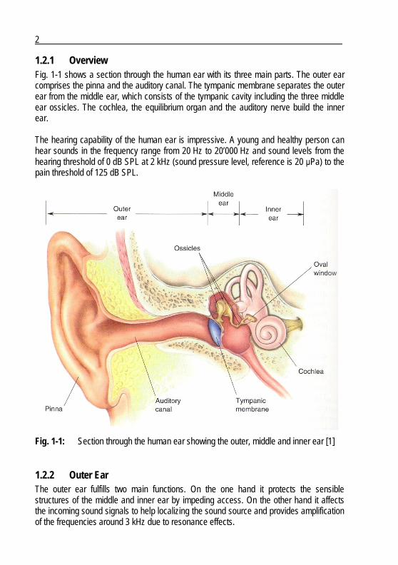
1.2.1 Overview Fig. 1-1 shows a section through the human ear with its three main parts. The outer ear comprises the pinna and the auditory canal. The tympanic membrane separates the outer ear from the middle ear, which consists of the tympanic cavity including the three middle ear ossicles. The cochlea, the equilibrium organ and the auditory nerve build the inner ear. The hearing capability of the human ear is impressive. A young and healthy person can hear sounds in the frequency range from 20 Hz to 20’000 Hz and sound levels from the hearing threshold of 0 dB SPL at 2 kHz (sound pressure level, reference is 20 μPa) to the pain threshold of 125 dB SPL.
Fig. 1-1: Section through the human ear showing the outer, middle and inner ear [1]
1.2.2 Outer Ear The outer ear fulfills two main functions. On the one hand it protects the sensible structures of the middle and inner ear by impeding access. On the other hand it affects the incoming sound signals to help localizing the sound source and provides amplification of the frequencies around 3 kHz due to resonance effects.
3
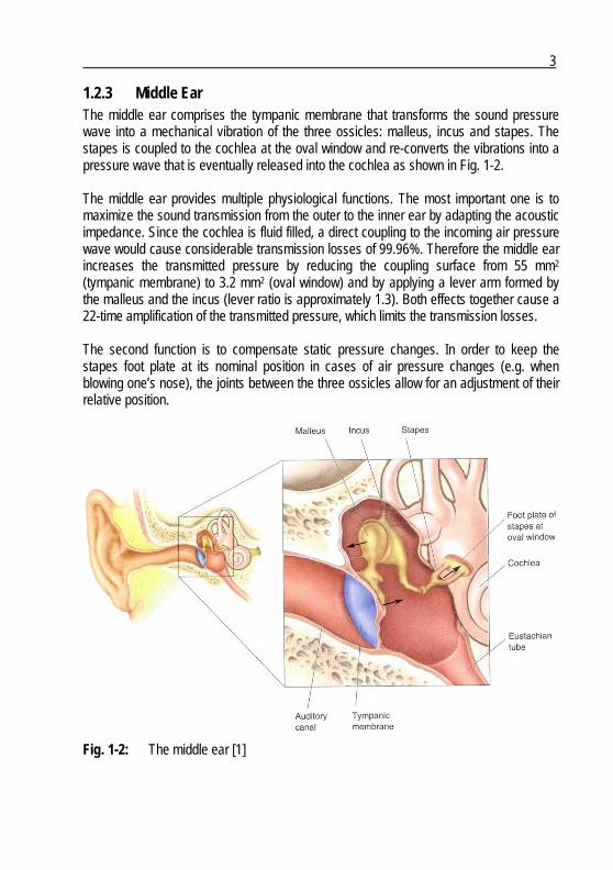
1.2.3 Middle Ear The middle ear comprises the tympanic membrane that transforms the sound pressure wave into a mechanical vibration of the three ossicles: malleus, incus and stapes. The stapes is coupled to the cochlea at the oval window and re-converts the vibrations into a pressure wave that is eventually released into the cochlea as shown in Fig. 1-2. The middle ear provides multiple physiological functions. The most important one is to maximize the sound transmission from the outer to the inner ear by adapting the acoustic impedance. Since the cochlea is fluid filled, a direct coupling to the incoming air pressure wave would cause considerable transmission losses of 99.96%. Therefore the middle ear increases the transmitted pressure by reducing the coupling surface from 55 mm2 (tympanic membrane) to 3.2 mm2 (oval window) and by applying a lever arm formed by the malleus and the incus (lever ratio is approximately 1.3). Both effects together cause a 22-time amplification of the transmitted pressure, which limits the transmission losses. The second function is to compensate static pressure changes. In order to keep the stapes foot plate at its nominal position in cases of air pressure changes (e.g. when blowing one’s nose), the joints between the three ossicles allow for an adjustment of their relative position.
Fig. 1-2: The middle ear [1]
4
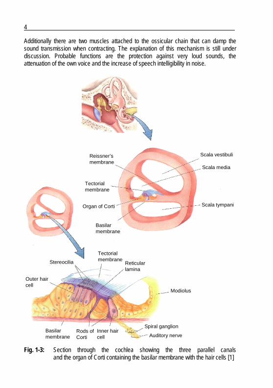
Additionally there are two muscles attached to the ossicular chain that can damp the sound transmission when contracting. The explanation of this mechanism is still under discussion. Probable functions are the protection against very loud sounds, the attenuation of the own voice and the increase of speech intelligibility in noise.
Reissner’smembrane
Scala vestibuli
Scala media
Scala tympani
Tectorialmembrane
Organ of Corti
Basilarmembrane
Basilarmembrane
Modiolus
Reticularlamina
TectorialmembraneStereocilia
Outer haircell
Rods ofCorti
Inner haircell Auditory nerve
Spiral ganglion
Reissner’smembrane
Scala vestibuli
Scala media
Scala tympani
Tectorialmembrane
Organ of Corti
Basilarmembrane
Basilarmembrane
Modiolus
Reticularlamina
TectorialmembraneStereocilia
Outer haircell
Rods ofCorti
Inner haircell Auditory nerve
Spiral ganglion
Fig. 1-3: Section through the cochlea showing the three parallel canals and the organ of Corti containing the basilar membrane with the hair cells [1]
5
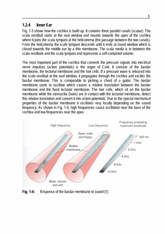
1.2.4 Inner Ear Fig. 1-3 shows how the cochlea is build up. It contains three parallel canals (scalae). The scala vestibuli starts at the oval window and mounts towards the apex of the cochlea where it joins the scala tympani at the helicotrema (the passage between the two canals). From the helicotrema the scale tympani descends until it ends at round window which is closed towards the middle ear by a thin membrane. The scala media is in between the scala vestibule and the scala tympani and represents a self-contained volume. The most important part of the cochlea that converts the pressure signals into electrical nerve impulses (action potentials) is the organ of Corti. It consists of the basilar membrane, the tectorial membrane and the hair cells. If a pressure wave is released into the scala vestibuli at the oval window, it propagates through the cochlea and excites the basilar membrane. This is comparable to picking a chord of a guitar. The basilar membrane starts to oscillate which causes a relative translation between the basilar membrane and the fixed tectorial membrane. The hair cells, which sit on the basilar membrane while the stereocilia (hairs) are in contact with the tectorial membrane, detect this relative translation and convert it into action potentials. Due to the special mechanical properties of the basilar membrane it oscillates very locally depending on the sound frequency. As shown in Fig. 1-4, high frequencies cause oscillation near the base of the cochlea and low frequencies near the apex.
Fig. 1-4: Response of the basilar membrane to sound [1]
6
1.3 Hearing Disorders
1.3.1 Types of Hearing Loss There are two main steps from a sound pressure signal to the corresponding perception in the auditory center of the brain. First, the sound pressure signal has to be “conducted” through the outer and the middle ear to the inner ear. If this sound transmission is impaired in some way, a conductive hearing loss is the consequence. In a second step, the hair cells transform the movements of the inner ear liquid into action potentials that are transmitted through the auditory nerve to the auditory center of the brain. An impairment of this part of the sound transmission and perception is called sensorineural hearing loss. Cases that combine conductive and sensorineural hearing losses are called combined or mixed hearing loss.
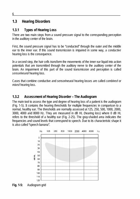
1.3.2 Assessment of Hearing Disorder – The Audiogram The main tool to assess the type and degree of hearing loss of a patient is the audiogram (Fig. 1-5). It contains the hearing thresholds for multiple frequencies in comparison to a normal, healthy ear. The thresholds are normally assessed at 125, 250, 500, 1000, 2000, 3000, 4000 and 8000 Hz. They are measured in dB HL (hearing loss) where 0 dB HL refers to the threshold of a healthy ear (Fig. 2-25). The gray-shaded area indicates the frequencies and sound levels that correspond to speech. Due to its characteristic shape it is also called “speech banana”.
Fig. 1-5: Audiogram grid

7
Two different hearing thresholds can be assessed: air conduction thresholds and bone conduction thresholds. To assess the air conduction thresholds, pure tones are provided to the patient by earphones. For each assessed frequency the sound level is continuously increased until the patient perceives the signal. The air conduction thresholds are indicated by circles in case of a right and crosses in case of a left ear. This measurement assesses the overall hearing loss, i.e. the sum of conductive and sensorineural hearing loss. The bone conduction thresholds are assessed in the same way as the air conduction thresholds but instead of providing a sound pressure signal, corresponding vibrations are applied on the patient’s temple. A special bone conduction headset containing a transducer that generates vibrations is used for this purpose. These vibrations bypass the outer and middle ear and are directly transmitted to the inner ear through the cranial bones. Therefore this measurement only assesses the sensorineural part of a hearing loss. The bone conduction thresholds are indicated by “>” in case of a right and “<” in case of a left ear. The difference between these two thresholds is called air-bone-gap and indicates the conductive loss. Fig. 1-6 shows an example of a patient that suffers from profound mixed hearing loss. Since air and bone conduction thresholds are not congruent, they form an air-bone-gap indicating the conductive loss of the patient. The sensorineural loss is indicated by the bone conduction thresholds. The overall loss is shown by the air conduction thresholds
Air-bone-gapAir-bone-gap
Fig. 1-6: Audiogram indicating air and bone conduction thresholds of a left ear

8
representing the actual impairment of the patient. One can see that the air conduction thresholds are far below the area where a normal conversation takes place (speech banana). Hence this patient would not hear a person talking to him at normal sound levels. The goal of every hearing therapy is therefore to lift the thresholds in aided condition close to the upper edge of the speech banana.
1.4 Hearing Therapies
1.4.1 Overview Fig. 1-7 maps the existing hearing therapies according to the degree and type of hearing loss [2] - [4]. It can be observed that pure sensorineural and pure conductive losses are well covered by known therapies. This is not the case with severe to profound mixed hearing loss. Only a combination of two therapies could partially restore the hearing of
0 dB
20 dB
40 dB
60dB
80 dB
100 dB
120 dB
Deg
ree
of
Hea
rin
g L
oss
Type of Hearing Loss
Sensori-neural
Mixed Conduc-tive
Mild
Moderate
Moderatelysevere
Severe
Profound
Deaf
MEIHA
CI
MES
DACS
BAHA
0 dB
20 dB
40 dB
60dB
80 dB
100 dB
120 dB
Deg
ree
of
Hea
rin
g L
oss
Type of Hearing Loss
Sensori-neural
Mixed Conduc-tive
Mild
Moderate
Moderatelysevere
Severe
Profound
Deaf
MEIHA
CI
MES
DACS
BAHA
Fig. 1-7: Overview of hearing therapies according to degree and type of hearing loss. HA: conventional hearing aids, MES: middle ear surgery, CI: cochlear implants, MEI: middle ear implants, BAHA: bone anchored hearing aids and, DACS: direct acoustic cochlear stimulation, modified after [2]

9
patients with such impairment. Therefore the goal of the present project was to develop a dedicated therapy for severe to profound mixed hearing loss based on an implantable hearing device (gray-shaded area). The corresponding direct acoustic cochlea stimulation (DACS) approach is described in sub-section 1.5.2.
1.4.2 Hearing Aids Hearing aids are the most widely-used hearing therapy. Approximately 6 - 7 million units are sold per year [5]. They are used to treat pure sensorineural and mild to moderate mixed hearing loss. By principle they are not adapted to treat conductive hearing loss since they rely on a functional middle ear for sound transmission. Any sound signal would therefore be damped by the conductive impairment. The operation principle of conventional hearing aids is as follows: They collect sound by one or more microphones, amplify it according to the hearing impairment of the patient and emit the amplified sound into the auditory canal. Fig. 1-8 shows different implementations of conventional hearing aids. Their size increases in general with the provided output power. A CIC is indicated for mild to moderate hearing loss, where a BTE is able to threat severe hearing loss.
Fig. 1-8: Conventional hearing aids, from left to the right: completely in the canal
device (CIC), in the canal device (ITC), micro behind the ear device (micro BTE), behind the ear device (BTE) [6]
1.4.3 Middle Ear Surgery Middle ear surgery is able to restore conductive hearing loss by the implantation of passive prostheses. Missing, injured or immobile structures can be replaced by corresponding artificial structures. Fig. 1-9 shows three examples. A stapes prosthesis is used in case of an immobile stapes (otosclerosis). After removing the stapes supra-structure and having drilled a hole into the immobile foot plate, the

10
stapes prosthesis is placed into the hole in the foot plate and attached to the incus. In this way the sound transmission is again unobstructed from the outer to the inner ear. This surgical technique is called stapedectomy [7], [8]. A total ossicular chain replacement prosthesis (TORP) is coupled to the inner ear like a stapes prosthesis, but replaces all the three ossicles. The wheel shaped part is therefore placed directly on the tympanic membrane. If the joint between the incus and the stapes (incudo-stapedial joint) is injured, it is possible to remove the tip of the long incus process and to reestablish the ossicular chain with help of the prosthesis shown on the right.
Fig. 1-9: Middle ear prostheses: stapes prosthesis on the left, total ossicular chain replacement prosthesis (TORP) in the middle and replacement of incudo-stapedial joint on the right [9]
1.4.4 Bone anchored hearing aids A bone anchored hearing aid (Fig. 1-10) is an alternative treatment for conductive hearing loss and can also be used in case of mild mixed hearing loss. It consists of a vibrating device that is coupled to the cranial bone by means of an implanted bone screw. The
Fig. 1-10: Bone anchored hearing aid: screw implant on the left, percutaneous abutment in the middle and external vibrator on the right [10]
11
vibrating device itself stays outside the head and is attached to the implanted screw via a percutaneous abutment. The vibrations are transmitted through the cranial bone directly to the inner ear while bypassing the outer and middle ear. For this reason it does not rely on a functional outer nor middle ear and is adapted to treat conductive hearing loss. The transmitted vibrations are on the other hand not strong enough to compensate for moderate to profound sensorineural hearing loss.
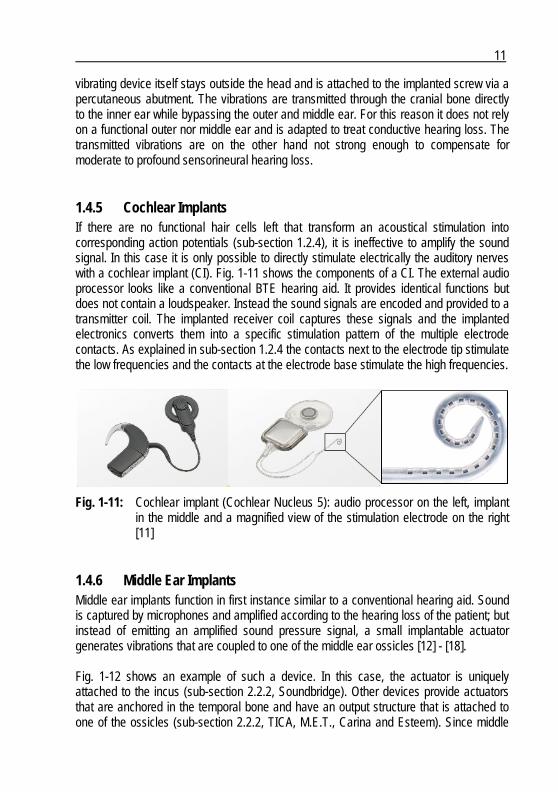
1.4.5 Cochlear Implants If there are no functional hair cells left that transform an acoustical stimulation into corresponding action potentials (sub-section 1.2.4), it is ineffective to amplify the sound signal. In this case it is only possible to directly stimulate electrically the auditory nerves with a cochlear implant (CI). Fig. 1-11 shows the components of a CI. The external audio processor looks like a conventional BTE hearing aid. It provides identical functions but does not contain a loudspeaker. Instead the sound signals are encoded and provided to a transmitter coil. The implanted receiver coil captures these signals and the implanted electronics converts them into a specific stimulation pattern of the multiple electrode contacts. As explained in sub-section 1.2.4 the contacts next to the electrode tip stimulate the low frequencies and the contacts at the electrode base stimulate the high frequencies.
Fig. 1-11: Cochlear implant (Cochlear Nucleus 5): audio processor on the left, implant in the middle and a magnified view of the stimulation electrode on the right [11]
1.4.6 Middle Ear Implants Middle ear implants function in first instance similar to a conventional hearing aid. Sound is captured by microphones and amplified according to the hearing loss of the patient; but instead of emitting an amplified sound pressure signal, a small implantable actuator generates vibrations that are coupled to one of the middle ear ossicles [12] - [18]. Fig. 1-12 shows an example of such a device. In this case, the actuator is uniquely attached to the incus (sub-section 2.2.2, Soundbridge). Other devices provide actuators that are anchored in the temporal bone and have an output structure that is attached to one of the ossicles (sub-section 2.2.2, TICA, M.E.T., Carina and Esteem). Since middle

12
ear implants use the ossicular chain as a coupling structure to transmit the vibrations to the inner ear, they are not indicated for conductive or mixed hearing loss.
Fig. 1-12: Middle ear implant (Vibrant Soundbridge): actuator on the left, external audio processor in the middle and implant electronics on the right [19]
1.5 DACS Therapy Concept
1.5.1 State of the Art As presented in sub-section 1.4.1, there is not yet a dedicated therapy for severe to profound mixed hearing loss. Patients are normally treated either with a conventional hearing aid or the combination of a conventional hearing aid and stapedectomy. This combined therapy, which is considered as reference for this project, provides better results than a hearing aid only but includes the drawbacks of both therapies. A direct comparison between this reference method and the DACS therapy will be the major outcome of the clinical study and will be presented in section 5.3. Recently there were a lot of efforts made to expand the indication of existing middle ear implants for mixed hearing loss. Since these devices originally relied on a functional middle ear, it was necessary to modify them and to develop new surgical techniques. The Vibrant Soundbridge was recently approved for the treatment of mixed hearing loss. In this case, the device is not attached to the ossicular chain but is rather placed on the round window membrane to bypass the middle ear [20]. A similar approach is under investigation for the Carina device. Here, the actuator is coupled to the round window membrane as well by means of specially shaped coupling elements [21].
13
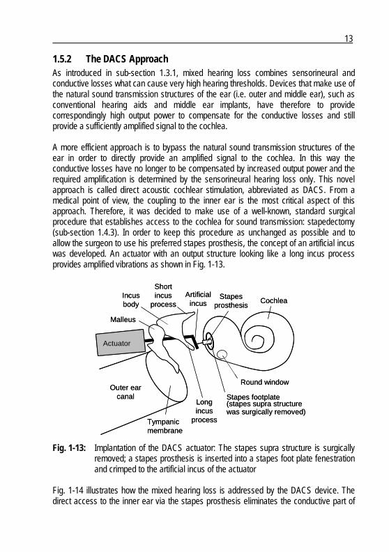
1.5.2 The DACS Approach As introduced in sub-section 1.3.1, mixed hearing loss combines sensorineural and conductive losses what can cause very high hearing thresholds. Devices that make use of the natural sound transmission structures of the ear (i.e. outer and middle ear), such as conventional hearing aids and middle ear implants, have therefore to provide correspondingly high output power to compensate for the conductive losses and still provide a sufficiently amplified signal to the cochlea. A more efficient approach is to bypass the natural sound transmission structures of the ear in order to directly provide an amplified signal to the cochlea. In this way the conductive losses have no longer to be compensated by increased output power and the required amplification is determined by the sensorineural hearing loss only. This novel approach is called direct acoustic cochlear stimulation, abbreviated as DACS. From a medical point of view, the coupling to the inner ear is the most critical aspect of this approach. Therefore, it was decided to make use of a well-known, standard surgical procedure that establishes access to the cochlea for sound transmission: stapedectomy (sub-section 1.4.3). In order to keep this procedure as unchanged as possible and to allow the surgeon to use his preferred stapes prosthesis, the concept of an artificial incus was developed. An actuator with an output structure looking like a long incus process provides amplified vibrations as shown in Fig. 1-13.
Stapes footplate(stapes supra structurewas surgically removed)
Cochlea
Actuator
Outer earcanal
Stapesprosthesis
Tympanicmembrane
Round window
Incusbody
Malleus
Longincus
process
Artificialincus
Shortincus
process
Stapes footplate(stapes supra structurewas surgically removed)
Cochlea
Actuator
Outer earcanal
Stapesprosthesis
Tympanicmembrane
Round window
Incusbody
Malleus
Longincus
process
Artificialincus
Shortincus
process
Fig. 1-13: Implantation of the DACS actuator: The stapes supra structure is surgically removed; a stapes prosthesis is inserted into a stapes foot plate fenestration and crimped to the artificial incus of the actuator
Fig. 1-14 illustrates how the mixed hearing loss is addressed by the DACS device. The direct access to the inner ear via the stapes prosthesis eliminates the conductive part of
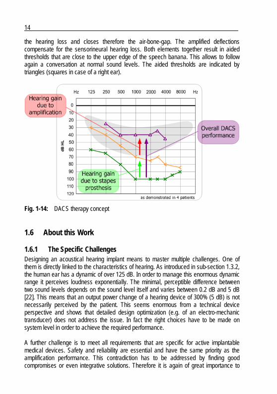
14
the hearing loss and closes therefore the air-bone-gap. The amplified deflections compensate for the sensorineural hearing loss. Both elements together result in aided thresholds that are close to the upper edge of the speech banana. This allows to follow again a conversation at normal sound levels. The aided thresholds are indicated by triangles (squares in case of a right ear).
Fig. 1-14: DACS therapy concept
1.6 About this Work
1.6.1 The Specific Challenges Designing an acoustical hearing implant means to master multiple challenges. One of them is directly linked to the characteristics of hearing. As introduced in sub-section 1.3.2, the human ear has a dynamic of over 125 dB. In order to manage this enormous dynamic range it perceives loudness exponentially. The minimal, perceptible difference between two sound levels depends on the sound level itself and varies between 0.2 dB and 5 dB [22]. This means that an output power change of a hearing device of 300% (5 dB) is not necessarily perceived by the patient. This seems enormous from a technical device perspective and shows that detailed design optimization (e.g. of an electro-mechanic transducer) does not address the issue. In fact the right choices have to be made on system level in order to achieve the required performance. A further challenge is to meet all requirements that are specific for active implantable medical devices. Safety and reliability are essential and have the same priority as the amplification performance. This contradiction has to be addressed by finding good compromises or even integrative solutions. Therefore it is again of great importance to
15
make the right conceptual choices on system level and to primarily consider all the specific requirements during the whole design process. The conceptual design phase of an acoustic hearing implant is essential because it provides the basis for the subsequent design steps and already defines its major device characteristics and performance. Specific implantable device requirements and other fundamental design aspects that are not considered at this stage can only be implemented with difficulties and increased efforts later on. In a worst case scenario, bad choices or neglected requirements during the conceptual design phase can cause fundamental device drawbacks that cannot be corrected anymore.
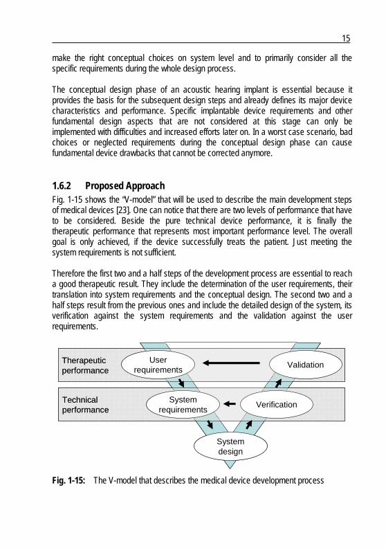
1.6.2 Proposed Approach Fig. 1-15 shows the “V-model” that will be used to describe the main development steps of medical devices [23]. One can notice that there are two levels of performance that have to be considered. Beside the pure technical device performance, it is finally the therapeutic performance that represents most important performance level. The overall goal is only achieved, if the device successfully treats the patient. Just meeting the system requirements is not sufficient. Therefore the first two and a half steps of the development process are essential to reach a good therapeutic result. They include the determination of the user requirements, their translation into system requirements and the conceptual design. The second two and a half steps result from the previous ones and include the detailed design of the system, its verification against the system requirements and the validation against the user requirements.
Therapeuticperformance
Userrequirements
Validation
Technicalperformance
Systemrequirements
Systemdesign
Verification
Therapeuticperformance
Userrequirements
Validation
Technicalperformance
Systemrequirements
Systemdesign
Verification
Fig. 1-15: The V-model that describes the medical device development process

16
In many cases the five design steps are executed in succession and by different people. For example, the user requirements are determined by doctors. The system requirements are written by a project leader and split into different system building blocks which are then designed by corresponding design teams. This approach entails the risks of losing the relation to the initial user requirements. This can result in a system that meets the system requirements but not necessarily the user requirements. In order to minimize this risk, it is proposed to merge the first two and a half steps into one conceptual design process as shown in Fig. 1-16. A system engineer that follows the whole design process has to be involved from the beginning in order to understand the impact of the design decisions on the therapeutic system performance. The challenge is now to keep the overview and to structure all the information of the parallelized steps. A corresponding methodology is the central part of this thesis and is presented in chapter 2.
Proposedconceptualdesignprocess
Userrequirements
Validation
Systemrequirements
Verification
Conceptualdesign
Detaileddesign
Proposedconceptualdesignprocess
Userrequirements
Validation
Systemrequirements
Verification
Conceptualdesign
Detaileddesign
Conceptualdesign
Detaileddesign
Fig. 1-16: Merging of the first two and half steps into one conceptual design process
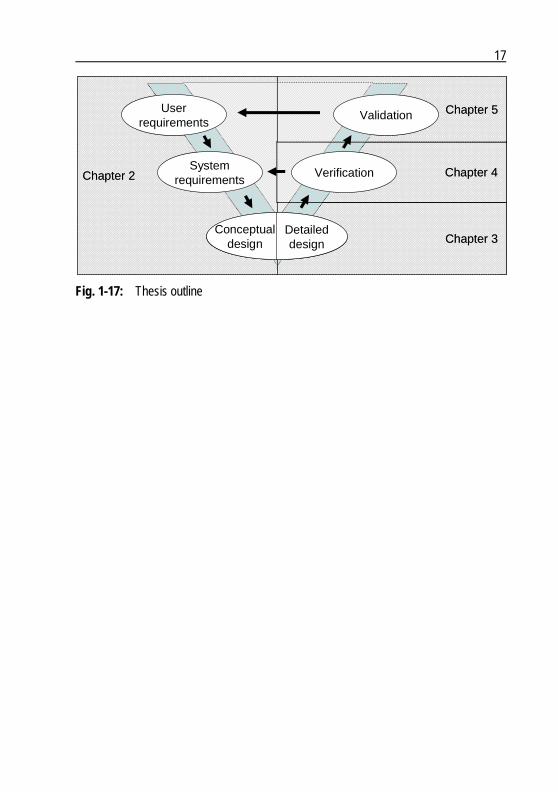
1.6.3 Thesis Outline Fig. 1-17 shows how this thesis is structured. The chapters follow the different steps of the V-model. The proposed conceptual design methodology is presented in chapter 2. Chapter 3 presents the investigational DACS device including a summary of the detailed actuator design process. The system verification tests and corresponding results are shown in chapter 4. The clinical study and its outcome, the validation of the system against the user requirements are summarized in chapter 5. Finally, chapter 6 contains the conclusions and an outlook on future projects.
17
Chapter 2
Userrequirements
Systemrequirements
Chapter 3
Chapter 4
Chapter 5 Validation
Verification
Conceptualdesign
Detaileddesign
Chapter 2
Userrequirements
Systemrequirements
Chapter 3
Chapter 4
Chapter 5 Validation
Verification
Conceptualdesign
Detaileddesign
Chapter 2
Userrequirements
Systemrequirements
Chapter 3
Chapter 4
Chapter 5 Validation
Verification
Conceptualdesign
Detaileddesign
Conceptualdesign
Detaileddesign
Fig. 1-17: Thesis outline

19
2 Conceptual Design Methodology for Acoustic Hearing Implants
2.1 Introduction The major challenges that have to be addressed by the proposed conceptual design methodology are presented in sub-sections 1.6.1 and 1.6.2. In short, they consist in:
Understanding exactly the hearing mechanisms and the corresponding user requirements
Understanding the specific requirements of active implantable medical devices Translating the user requirements correctly into system requirements Considering all relevant requirements at each design step Making the right choices on concept level in order to maximize the system and,
finally, the therapeutic performance A two-step investigation is done in order to complete the above list. First, references on how to design an acoustic hearing implant are presented (sub-section 2.2.1). Second, the already existing acoustic hearing implants are analyzed (sub-section 2.2.2). Finally, sub-section 2.2.3 summarizes the outcome of the investigation and completes the above list.
2.2 State of the Art
2.2.1 Design Methodology There are numerous conceptual design methodologies that can be used for a general device development. Shah [24] has listed and categorized the most widely used methodologies like the use of design catalogues, morphological analysis, brainstorming or 6-3-5, to just mention some examples. All these methodologies are valuable tools to find solutions for well defined and delimited problems. Therefore they serve to find solutions once the system is already well structured and all relevant requirements for all system functions are defined. This is the case only at the end of the whole conceptual design process as defined in sub-section 1.6.2 and corresponds to the step 4 of the proposed methodology (sub-section 2.3.7). They do not address the design challenges listed in section 2.1 which require an analysis-and-structuring-tool and not primarily a solution-finding-tool. A more comprehensive approach to the development and design of technical systems and products is given by the VDI standard 2221 [25]. It describes a methodology
20
that incorporates the whole design process from the definition of requirements to specification of the final product. It mentions the early design phases like the analysis of the underlying problem and the resulting definition of system requirements as well as the necessity to structure the primary interrelationships of the system. Nevertheless, there is only a rather superficial and no detailed description of these essential phases. A description of tools that would support these phases is missing. The aforementioned references provide methodologies that can be applied to design problems in general and do not take into account the specific aspects of an acoustic hearing implant. A literature study in the field of implantable hearing aids was conducted but did not provide a well developed conceptual design methodology. There are few articles that discuss basic requirements and design aspects of acoustic hearing implants, but they do not help the designer to specify requirements and to derive optimal solutions from them. Ko et al. [26] for example mention that medical and engineering aspects have to be considered. However the medical aspects are neglected and the article concentrates on transducer principles and their technical characteristics. Only the human ear transfer functions are investigated in more detail but without discussing the relation with the different transducer principles. Leysieffer et al. provide a detailed list of the user and system requirements of an actuator for acoustic hearing implants [27], [28]. This includes technical performance as well as medical characteristics. They further mention that the major challenge of the development of such an actuator is to manage partially contradictory requirements and to find the best compromise solutions. Even if their approach seems very complete and well investigated, the resulting TICA device showed an insufficient therapeutic performance. Possible reasons are discussed in sub-section 2.2.2.
2.2.2 Analysis of Existing Acoustic Hearing Implants
Overview The era of acoustic hearing implants started in the late 1970s with the use of BAHA devices, followed by the first implantation of the Rion E-type device in 1987. Since then, multiple devices were developed, manufactured and implanted. Table 2-1 gives an overview over the most relevant devices. Some of them are analyzed in more detail in the subsequent sub-sections.

21
Table 2-1: Overview of existing acoustic hearing implants
Device Name
Manufac-turer
Implant Type
Indicated Hearing Loss
Coupling Site
Avai-lable
Actuator Type
TICA Implex fully sensorineural Incus no Piezo disc
M.E.T. Otologics semi sensorineural Incus no Electro-mechanic
Carina Otologics fully sensorineural, mixed
Incus, round window
yes Electro-mechanic
Sound-bridge
MED-EL semi sensorineural, mixed
Incus, round window
yes Electro-magnetic
Esteem Envoy Medical
fully sensorineural Stapes yes Piezo strip
E-type Rion semi sensorineural Stapes no Piezo strip
Direct Drive Hearing System
Soundtec semi sensorineural Incudo-stapedial joint
no Electro-magnetic
BAHA Cochlear semi conductive, (mixed)
Cranial bone
yes Electro-mechanic
TICA – Totally Implantable Cochlear Amplifier from Implex The TICA was the first totally implantable middle ear implant [29], [30]. It consists of a microphone placed in the auditory canal wall, an actuator placed in the mastoid bone and an electronics unit implanted behind the ear, between skull and skin. The actuator is coupled to the incus body (Fig. 2-1). The device was CE marked in 1999 and implanted approximately 20 times [31]. There are two probable reasons for stopping the implantations. On the one hand, the device gain is very limited due to feedback between the actuator and the microphone [31]. The three feedback paths (acoustic, mechanic and electronic) were probably neglected or underestimated during the design and verification phases. Only when the device was implanted in its final configuration the feedback occurred. This indicates that system level verification was not sufficient and that the interactions between the different system

22
components as well as the interactions with the surrounding tissues were not sufficiently considered. On the other hand, the actuator itself (Fig. 2-2) provides a frequency response that is not well adjusted to the natural frequency response of the ear as shown in Fig. 2-3. The resonance frequency of the actuator is significantly higher than the natural resonance of the human ear. Therefore the actuator efficiency increases with frequency but is rather limited at frequencies below 1.5 kHz [31]. This unbalanced characteristic restricts the indication of the device to patients with high frequency hearing loss.
Fig. 2-1: Schematic representation of the implanted TICA system: the microphone is placed close to the actuator and both are anchored in the same bone [32]
Titanium diaphragm
Polymer sealHermetic feedthrough
Piezo disc
Coupling rod
Titanium diaphragm
Polymer sealHermetic feedthrough
Piezo disc
Coupling rod
Fig. 2-2: Longitudinal section through the TICA actuator, modified after [30]

23
The TICA actuator is a good example that shows how a conceptual choice limits the device performance without the possibility to improve it by optimization during the detailed design phase. As Fig. 2-3 shows, the actuator is too rigid, resulting in a too high resonance frequency. The selected actuation principle of a piezo-electric disc bender did not allow for sufficient adaptation of the design parameters. The diameter of the disc bender could not be further increased to decrease its rigidity because the available space in the mastoid bone is restricted. The thickness of the disc bender could not be decreased neither, due to actual limits of the piezo disc fabrication.
Fig. 2-3: Frequency response of the TICA actuator (continuous line) in comparison with the natural stapes deflection characteristic (dashed line) [30]
M.E.T. / Carina from Otologics To date, Otologics brought two products on the market. The initial M.E.T. was a semi-implantable device that is now replaced by the Carina, which is a fully implantable device [33] - [35]. Both implants are equipped with the same actuator shown in Fig. 2-4. It is based on a standard balanced armature actuator that is widely used for loudspeakers of conventional hearing aids. This balanced armature actuator is encapsulated in a hermetic titanium housing in order to meet the biocompatibility requirements. This conceptual approach causes a major challenge: the generated deflections have to be fed through the hermetic encapsulation without damping them too much. Since the frequency response is already given by the selected actuator, it is necessary to minimize the impact of the encapsulation. The technical solution consists of a sophisticated bellows

24
structure (Fig. 2-4) which is characterized by a high compliance. The fabrication of such a thin bellows structure is a technological challenge that is difficult to cope with. Consequently, the first generation of implanted actuators became leaky after a while because the bellows started to disintegrate.
Coil
Feedthrough
Couplingrod
Armature
Bellows
Lead
Magnets andsoft magneticstructure
Coil
Feedthrough
Couplingrod
Armature
Bellows
Lead
Magnets andsoft magneticstructure
Fig. 2-4: Longitudinal section through the Carina actuator, modified after [36] This is another example that shows the consequence of conceptual decisions. The decision to use an existing actuator technology that was initially designed for another application forced the engineers to find an almost impossible compromise between hermeticity, compliance and reliability for the encapsulation. Instead of looking for an integrated solution considering encapsulation and actuator, all the demanding requirements were put on the encapsulation side. The patient selection criteria shown in Fig. 2-5 indicate two more implications of the device concept on the device performance. One can observe that the semi-implantable device is indicated for patient with more severe hearing loss than the fully implantable device. One reason is probably a more limited gain of the fully implantable device due to feedback between the actuator and the implanted microphone (like TICA). Further, the device amplification seems to be lower at low frequencies than at higher ones. This indicates that the frequency response of the actuator is not well adapted to the natural frequency response of the human ear (cf. TICA). The probable reason is the same as for the hermeticity problem, namely the bellows encapsulation. The additional rigidity of the bellows (even if it was minimized) caused a frequency response with increased resonance frequency.
25
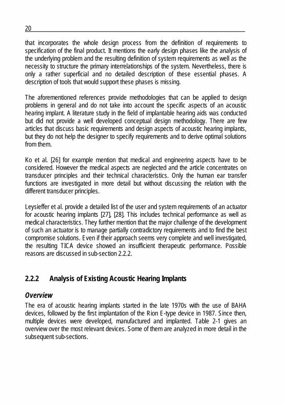
Fig. 2-5: Patient selection criteria for the semi and fully implantable Otologics device [37], [38]
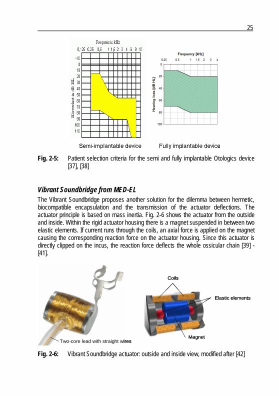
Vibrant Soundbridge from MED-EL The Vibrant Soundbridge proposes another solution for the dilemma between hermetic, biocompatible encapsulation and the transmission of the actuator deflections. The actuator principle is based on mass inertia. Fig. 2-6 shows the actuator from the outside and inside. Within the rigid actuator housing there is a magnet suspended in between two elastic elements. If current runs through the coils, an axial force is applied on the magnet causing the corresponding reaction force on the actuator housing. Since this actuator is directly clipped on the incus, the reaction force deflects the whole ossicular chain [39] - [41].
Two-core lead with straight wires
Elastic elements
Coils
MagnetTwo-core lead with straight wires
Elastic elements
Coils
Magnet
Fig. 2-6: Vibrant Soundbridge actuator: outside and inside view, modified after [42]
26
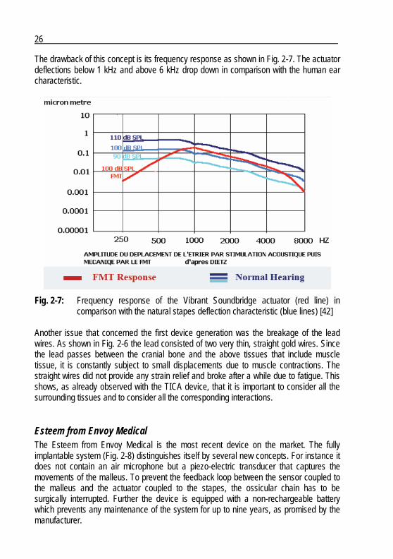
The drawback of this concept is its frequency response as shown in Fig. 2-7. The actuator deflections below 1 kHz and above 6 kHz drop down in comparison with the human ear characteristic.
Fig. 2-7: Frequency response of the Vibrant Soundbridge actuator (red line) in comparison with the natural stapes deflection characteristic (blue lines) [42]
Another issue that concerned the first device generation was the breakage of the lead wires. As shown in Fig. 2-6 the lead consisted of two very thin, straight gold wires. Since the lead passes between the cranial bone and the above tissues that include muscle tissue, it is constantly subject to small displacements due to muscle contractions. The straight wires did not provide any strain relief and broke after a while due to fatigue. This shows, as already observed with the TICA device, that it is important to consider all the surrounding tissues and to consider all the corresponding interactions.
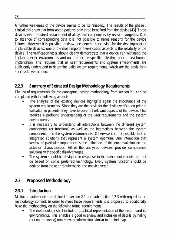
Esteem from Envoy Medical The Esteem from Envoy Medical is the most recent device on the market. The fully implantable system (Fig. 2-8) distinguishes itself by several new concepts. For instance it does not contain an air microphone but a piezo-electric transducer that captures the movements of the malleus. To prevent the feedback loop between the sensor coupled to the malleus and the actuator coupled to the stapes, the ossicular chain has to be surgically interrupted. Further the device is equipped with a non-rechargeable battery which prevents any maintenance of the system for up to nine years, as promised by the manufacturer.

27
Fig. 2-8: Esteem implant with magnified representation of the sensor and the actuator [32]
Unfortunately there is almost no technical data published so far, what makes it difficult to analyze the device. Nevertheless it is possible to draw some conclusions from the published clinical data. The patient selection criterion (Fig. 2-9), for example, shows that the device amplification is rather low below 1 kHz and increases at higher frequencies. This characteristic is very similar to the one of the TICA device and indicates as well that the actuator provides a frequency response that differs from the normal ear. Therefore the use of the device is restricted to patients with the corresponding hearing loss characteristic.
Fig. 2-9: Patient selection criterion for the Esteem device [32]
28
A further weakness of the device seems to be its reliability. The results of the phase I clinical trial show that from seven patients only three benefited from the device [43]. Three devices even required replacement of all system components by revision surgeries. Due to absence of corresponding data it is not possible to name reasons for the device failures. However it is possible to draw one general conclusion for the development of implantable devices: one of the most important verification aspects is the reliability of the device. The verification tests should clearly demonstrate that a device can withstand the implant specific environments and operate for the specified life time prior to first human implantation. This requires that all user requirements and system environments are sufficiently understood to determine valid system requirements, which are the basis for a successful verification.
2.2.3 Summary of Extracted Design Methodology Requirements The list of requirements for the conceptual design methodology from section 2.1 can be completed with the following aspects:
The analysis of the existing devices highlights again the importance of the system requirements. Since they are the basis for the device verification prior to validation in patients, they have to cover all relevant aspects of the device. This requires a profound understanding of the user requirements and the system environments.
It is necessary to understand all interactions between the different system components (or functions) as well as the interactions between the system components and the system environments. Otherwise it is not possible to find integrated solutions that represent a system optimum. One interaction that seems of particular importance is the influence of the encapsulation on the actuator characteristics. All of the analyzed devices provide compromise solutions with specific disadvantages.
The system should be designed in response to the user requirements and not be based on some preferred technology. Every system function should be derived from the user requirements and not vice versa.
2.3 Proposed Methodology
2.3.1 Introduction Multiple requirements are defined in section 2.1 and sub-section 2.2.3 with regard to the methodology content. In order to meet these requirements it is proposed to additionally base the methodology on the following formal requirements:
The methodology shall include a graphical representation of the system and its environments. This enables a good overview and inclusion of details by hiding (but not removing) non-relevant information, similar to a mind map.

29
The methodology shall follow of the V-model, by cumulating the information from the determination of the user requirements down to the conceptual design.
Fig. 2-10 shows an overview of the resulting conceptual design methodology. It consists of a step-by-step procedure and a diagram tool.
Conceptual Design Methodology
Inputs Outputs
Therapy goal
Given stakeholder requirements
User requirementsProcedure
Diagram tool
System requirements
Conceptual design
Conceptual Design Methodology
Inputs Outputs
Therapy goal
Given stakeholder requirements
User requirementsProcedure
Diagram tool
System requirements
Conceptual design
Fig. 2-10: Conceptual design methodology overview The diagram tool is presented in the following sub-sections:
Sub-section 2.3.2 introduces the symbols used for graphical representation of the system and defines the specific terms.
Sub-section 2.3.3 defines how the graphic representation of the system can be re-structured in order to approach an optimal system concept.
The procedure is described by applying the methodology to design the DACS system or parts of it. The necessary design inputs (therapy goal and stakeholder requirements) are very restricted, since the determination of most of the requirements is part of the methodology. In this case of the design of the DACS system the following design inputs are considered:
The system shall successfully treat patients with severe to profound mixed hearing loss.
The system shall consist of an external part based on a modified conventional hearing aid, a link through the skin and an implantable part that contains an actuator and a fixation system.
The coupling of the actuator to the cochlea shall be established with a stapes prosthesis that is placed like during a conventional stapedectomy.
The four procedure steps are presented in the following sub-sections:
Sub-section 2.3.4 presents the first of four steps of the actual methodology. It consists in analyzing the human ear and deriving the functions that shall be emulated by the system.

30
Sub-section 2.3.5 describes the second step that consists in transforming the previously defined functional diagram of the ear into a system diagram. This helps to get a first idea of the architecture and the main functions of the future system.
Sub-section 2.3.6 includes the third step. This central step describes how to determine the user requirements and how they are translated into system requirements.
Section 2.3.7 presents the fourth step that consists in working out the conceptual system design. This means that a solution for each function has to be found that responds to determined interfaces.
The final question will be how useful and efficient the proposed methodology is. The answer can only be given indirectly, based on resulting device characteristics. Only the validation of the therapeutic performance of the final device indicates if the concept is appropriate or not. The corresponding discussion is part of section 5.3.
2.3.2 Definition of Terms and Corresponding Diagram Symbols
Function / Sub-function A function or sub-function (Fig. 2-11) is the central element of the proposed methodology. The to-be-designed system is represented by a multitude of functions and sub-functions that are interlinked through interfaces. Initially the functions and sub-functions are considered as “black boxes” that are only characterized by their interfaces which specify their input and output quantities. The final goal will be to find a solution for each function and sub-function that provides the specified output quantity depending on the input quantity.
Function NameF1
Function Name F2
Sub-function NameF2.2
Function NameF1
Function Name F2
Sub-function NameF2.2
Fig. 2-11: Graphic symbols for functions and sub-functions
31
In general a function or sub-function has at least one interface that links it to a global environment or another function or sub-function. It is proposed to subdivide the identifier of the function in order to label the sub-function. A function or sub-function is represented as box with rounded corners and is labeled with function or sub-function name and identifier (Fx and Fx.x).
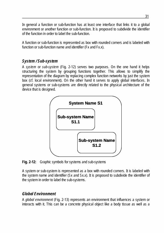
System / Sub-system A system or sub-system (Fig. 2-12) serves two purposes. On the one hand it helps structuring the system by grouping functions together. This allows to simplify the representation of the diagram by replacing complex function networks by just the system box (cf. local environment). On the other hand it serves to apply global interfaces. In general systems or sub-systems are directly related to the physical architecture of the device that is designed.
System Name S1
Sub-system NameS1.1
Sub-system NameS1.2
System Name S1
Sub-system NameS1.1
Sub-system NameS1.2
Fig. 2-12: Graphic symbols for systems and sub-systems A system or sub-system is represented as a box with rounded corners. It is labeled with the system name and identifier (Sx and Sx.x). It is proposed to subdivide the identifier of the system in order to label the sub-systems.
Global Environment A global environment (Fig. 2-13) represents an environment that influences a system or interacts with it. This can be a concrete physical object like a body tissue as well as a
32
project stakeholder or a regulatory authority. The global environments determine the system requirements. In contrast to a local environment, a global environment is not part of the to-be-designed system. A global environment is represented as an oval box placed around a system. The box is labeled with the name of the global environment and the corresponding identifier (Ex).
System NameS1
Environment NameE1
Environment NameE2
Environment NameE3
System NameS1
Environment NameE1
Environment NameE2
Environment NameE3
Fig. 2-13: Graphic symbols for global environments
Local Environment A local environment (Fig. 2-14) is a term introduced to designate a sub-system, function or sub-function seen from the perspective of a function or sub-function. This allows representing a specific function or sub-function with its whole context in a clearly arranged way (as it will be shown in sub-section 2.3.3).
Function NameF1
Environment NameE1
Function NameF2 Environment Name
E2
Sub-system NameS1.2
Function NameF1
Environment NameE1
Function NameF2 Environment Name
E2
Sub-system NameS1.2
Fig. 2-14: Function F2 and sub-system S1.2 are local environments of function F1
33
There is no dedicated symbol for a local environment, since it is represented by the corresponding sub-system, function or sub-function symbol.
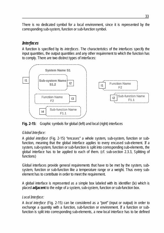
Interfaces A function is specified by its interfaces. The characteristics of the interfaces specify the input quantities, the output quantities and any other requirement to which the function has to comply. There are two distinct types of interfaces:
Sub-function NameF1.1
Function NameF2
I2
I1
Sub-function NameF1.1
Function NameF2
Sub-system NameS1.2
System Name S1
I3
I4
I2I1
Sub-function NameF1.1
Function NameF2
I2
I1
Sub-function NameF1.1
Function NameF2
I2
I1
Sub-function NameF1.1
Function NameF2
Sub-system NameS1.2
System Name S1
I3
I4
I2I1
Sub-function NameF1.1
Function NameF2
Sub-system NameS1.2
System Name S1
I3
I4
I2I1
Fig. 2-15: Graphic symbols for global (left) and local (right) interfaces Global Interface:
A global interface (Fig. 2-15) “encases” a whole system, sub-system, function or sub-function, meaning that the global interface applies to every encased sub-element. If a system, sub-system, function or sub-function is split into corresponding sub-elements, the global interface has to be applied to each of them. (cf. sub-section 2.3.3, Splitting of functions) Global interfaces provide general requirements that have to be met by the system, sub-system, function or sub-function like a temperature range or a weight. Thus every sub-element has to contribute in order to meet the requirement. A global interface is represented as a simple box labeled with its identifier (Ix) which is placed adjacent to the edge of a system, sub-system, function or sub-function box. Local Interface:
A local interface (Fig. 2-15) can be considered as a “port” (input or output) in order to exchange a quantity with a function, sub-function or environment. If a function or sub-function is split into corresponding sub-elements, a new local interface has to be defined
34
in between in order to link the original local interfaces. (cf. sub-section 2.3.3, Splitting of functions) Local interfaces specify input and output quantities like sound pressure or force. Thus, if the conversion from sound pressure to force is done in several steps, the intermediate quantities have to be attributed to intermediate local interfaces. A local interface is represented as a simple box labeled with its identifier (Ix) which is placed overlapping the edge of a function or sub-function box.
2.3.3 Definition of Diagram Drawing Rules
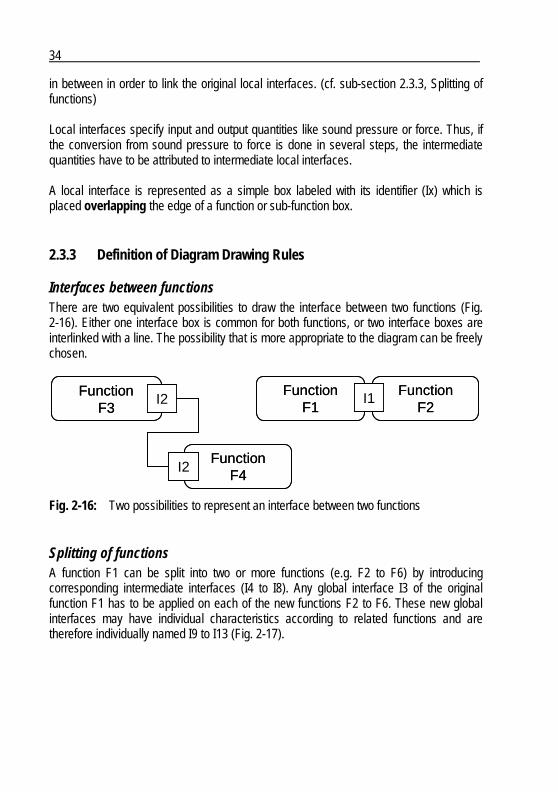
Interfaces between functions There are two equivalent possibilities to draw the interface between two functions (Fig. 2-16). Either one interface box is common for both functions, or two interface boxes are interlinked with a line. The possibility that is more appropriate to the diagram can be freely chosen.
FunctionF1
FunctionF3
FunctionF4
FunctionF2
I1
I2
I2Function
F1Function
F3
FunctionF4
FunctionF2
I1
I2
I2
Fig. 2-16: Two possibilities to represent an interface between two functions
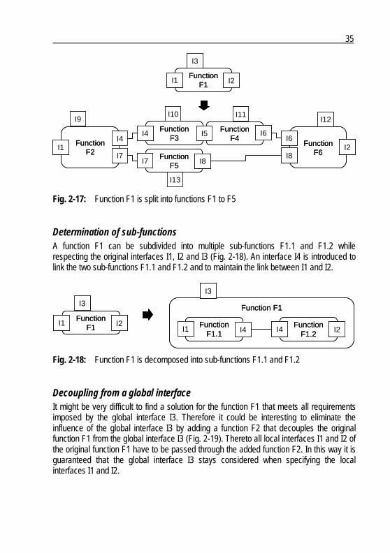
Splitting of functions A function F1 can be split into two or more functions (e.g. F2 to F6) by introducing corresponding intermediate interfaces (I4 to I8). Any global interface I3 of the original function F1 has to be applied on each of the new functions F2 to F6. These new global interfaces may have individual characteristics according to related functions and are therefore individually named I9 to I13 (Fig. 2-17).
35
FunctionF2
FunctionF3
I4I4
I10I9
FunctionF1
I1 I2
I3
I1Function
F5
FunctionF4
FunctionF6
I5
I7I7 I8
I8
I2I6
I6
I11I12
I13
FunctionF2
FunctionF3
I4I4
I10I9
FunctionF1
I1 I2
I3
I1Function
F5
FunctionF4
FunctionF6
I5
I7I7 I8
I8
I2I6
I6
I11I12
I13
Fig. 2-17: Function F1 is split into functions F1 to F5
Determination of sub-functions A function F1 can be subdivided into multiple sub-functions F1.1 and F1.2 while respecting the original interfaces I1, I2 and I3 (Fig. 2-18). An interface I4 is introduced to link the two sub-functions F1.1 and F1.2 and to maintain the link between I1 and I2.
FunctionF1
I1
Function F1
FunctionF1.2
FunctionF1.1
I2I1 I4I4 I2
I3
I3
FunctionF1
I1
Function F1
FunctionF1.2
FunctionF1.1
I2I1 I4I4 I2
I3
I3
Fig. 2-18: Function F1 is decomposed into sub-functions F1.1 and F1.2
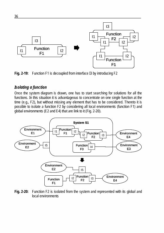
Decoupling from a global interface It might be very difficult to find a solution for the function F1 that meets all requirements imposed by the global interface I3. Therefore it could be interesting to eliminate the influence of the global interface I3 by adding a function F2 that decouples the original function F1 from the global interface I3 (Fig. 2-19). Thereto all local interfaces I1 and I2 of the original function F1 have to be passed through the added function F2. In this way it is guaranteed that the global interface I3 stays considered when specifying the local interfaces I1 and I2.
36
FunctionF2
FunctionF1
FunctionF1
I3
I1I1
I2
I3
I1 I2
I2
I1 I2
FunctionF2
FunctionF1
FunctionF1
I3
I1I1
I2
I3
I1 I2
I2
I1 I2
Fig. 2-19: Function F1 is decoupled from interface I3 by introducing F2
Isolating a function Once the system diagram is drawn, one has to start searching for solutions for all the functions. In this situation it is advantageous to concentrate on one single function at the time (e.g., F2), but without missing any element that has to be considered. Thereto it is possible to isolate a function F2 by considering all local environments (function F1) and global environments (E2 and E4) that are link to it (Fig. 2-20).
EnvironmentE1
System S1
FunctionF2
FunctionF1
FunctionF3
EnvironmentE3
EnvironmentE2
EnvironmentE4
I2I2
I5
I1I3
I4
FunctionF2
I2 I3
EnvironmentE2 I5
FunctionF1
EnvironmentE4
EnvironmentE1
System S1
FunctionF2
FunctionF1
FunctionF3
EnvironmentE3
EnvironmentE2
EnvironmentE4
I2I2
I5
I1I3
I4
FunctionF2
I2 I3
EnvironmentE2 I5
FunctionF1
EnvironmentE4
Fig. 2-20: Function F2 is isolated from the system and represented with its global and local environments
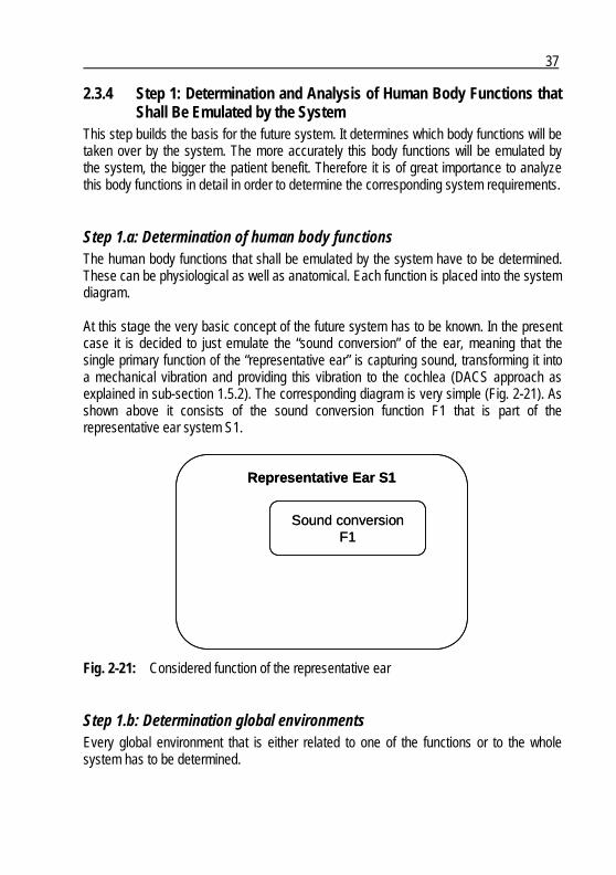
37
2.3.4 Step 1: Determination and Analysis of Human Body Functions that Shall Be Emulated by the System
This step builds the basis for the future system. It determines which body functions will be taken over by the system. The more accurately this body functions will be emulated by the system, the bigger the patient benefit. Therefore it is of great importance to analyze this body functions in detail in order to determine the corresponding system requirements.
Step 1.a: Determination of human body functions The human body functions that shall be emulated by the system have to be determined. These can be physiological as well as anatomical. Each function is placed into the system diagram. At this stage the very basic concept of the future system has to be known. In the present case it is decided to just emulate the “sound conversion” of the ear, meaning that the single primary function of the “representative ear” is capturing sound, transforming it into a mechanical vibration and providing this vibration to the cochlea (DACS approach as explained in sub-section 1.5.2). The corresponding diagram is very simple (Fig. 2-21). As shown above it consists of the sound conversion function F1 that is part of the representative ear system S1.
Representative Ear S1
Sound conversionF1
Representative Ear S1
Sound conversionF1
Fig. 2-21: Considered function of the representative ear
Step 1.b: Determination global environments Every global environment that is either related to one of the functions or to the whole system has to be determined.
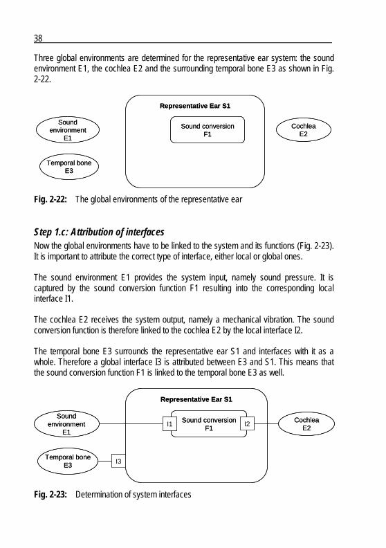
38
Three global environments are determined for the representative ear system: the sound environment E1, the cochlea E2 and the surrounding temporal bone E3 as shown in Fig. 2-22.
Soundenvironment
E1
Representative Ear S1
Sound conversionF1
Temporal boneE3
CochleaE2
Soundenvironment
E1
Representative Ear S1
Sound conversionF1
Temporal boneE3
CochleaE2
Fig. 2-22: The global environments of the representative ear
Step 1.c: Attribution of interfaces Now the global environments have to be linked to the system and its functions (Fig. 2-23). It is important to attribute the correct type of interface, either local or global ones. The sound environment E1 provides the system input, namely sound pressure. It is captured by the sound conversion function F1 resulting into the corresponding local interface I1. The cochlea E2 receives the system output, namely a mechanical vibration. The sound conversion function is therefore linked to the cochlea E2 by the local interface I2. The temporal bone E3 surrounds the representative ear S1 and interfaces with it as a whole. Therefore a global interface I3 is attributed between E3 and S1. This means that the sound conversion function F1 is linked to the temporal bone E3 as well.
Soundenvironment
E1
Representative Ear S1
Sound conversionF1
Temporal boneE3
CochleaE2
I2I1
I3
Soundenvironment
E1
Representative Ear S1
Sound conversionF1
Temporal boneE3
CochleaE2
I2I1
I3
Fig. 2-23: Determination of system interfaces
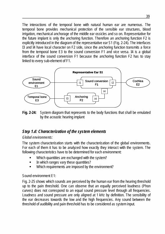
39
The interactions of the temporal bone with natural human ear are numerous. The temporal bone provides mechanical protection of the sensible ear structures, blood irrigation, mechanical anchorage of the middle ear ossicles and so on. Representative for the future implant is only the anchoring function. Therefore an anchoring function F2 is explicitly introduced in the diagram of the representative ear S1 (Fig. 2-24). The interfaces I3 and I4 have local character on F2 side, since the anchoring function transmits a force from the temporal bone E3 to the sound conversion F1 and vice versa. I4 is a global interface of the sound conversion F1 because the anchoring function F2 has to stay linked to every sub-element of F1.
Soundenvironment
E1
Representative Ear S1
Sound conversionF1
Temporal boneE3
CochleaE2
I2I1
AnchoringF2
I4
I3 I4
Soundenvironment
E1
Representative Ear S1
Sound conversionF1
Temporal boneE3
CochleaE2
I2I1
AnchoringF2
I4
I3 I4
Fig. 2-24: System diagram that represents to the body functions that shall be emulated by the acoustic hearing implant
Step 1.d: Characterization of the system elements Global environments:
The system characterization starts with the characterization of the global environments. For each of them it has to be analyzed how exactly they interact with the system. The following characteristics have to be determined for each environment:
Which quantities are exchanged with the system? In which ranges vary these quantities? Which requirements are imposed by the environment?
Sound environment E1:
Fig. 2-25 shows which sounds are perceived by the human ear from the hearing threshold up to the pain threshold. One can observe that an equally perceived loudness (Phon curves) does not correspond to an equal sound pressure level through all frequencies. Loudness and sound pressure are only aligned at 1 kHz by definition. The sensibility of the ear decreases towards the low and the high frequencies. Any sound between the threshold of audibility and pain threshold has to be considered as system input.

40
Fig. 2-25: Hearing (dashed curve) and pain thresholds (red curve) in the human, the “Phon curves” correspond to equally perceived loudness according to [44]
Cochlea E2:
The stapes generates a pressure wave that is propagated in the cochlea and causes deflection of the basilar membrane. The movements of the stapes have a specific frequency characteristic as shown in Fig. 2-26. If a constant sound pressure is applied in front of the tympanic membrane, the stapes velocity increases with approximately 20 dB per decade until 1 kHz, then it decreases with approximately 20 dB per decade. Temporal bone E3:
The temporal bone is a very hard bone that surrounds the whole hearing organ. Since it is only considered for anchoring, there are no other characteristics to consider than the mechanical properties of bones. Interfaces:
These interfaces are body tissues that have to be replaced later on by some technologies (see step 2). Therefore their characteristics are important to know:
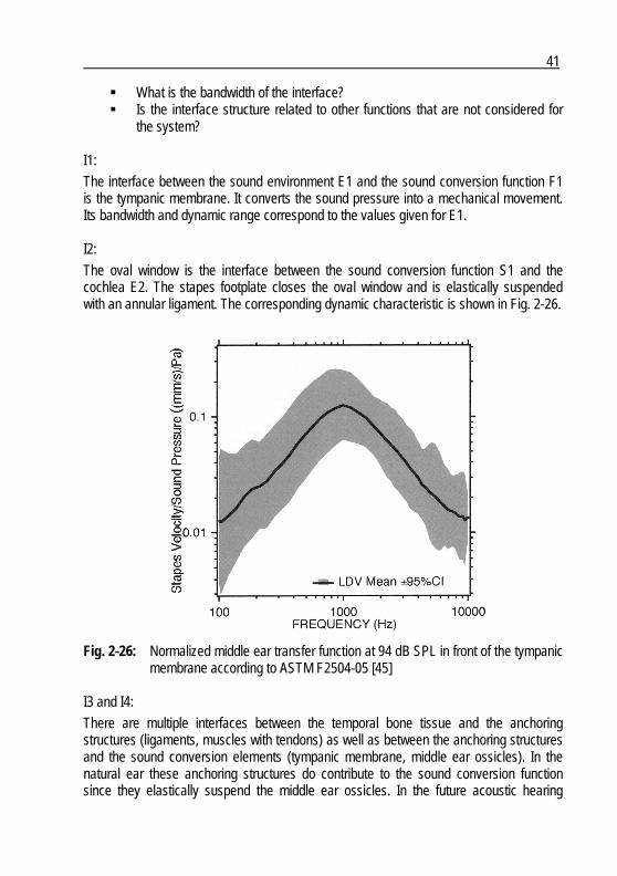
41
What is the bandwidth of the interface? Is the interface structure related to other functions that are not considered for
the system? I1:
The interface between the sound environment E1 and the sound conversion function F1 is the tympanic membrane. It converts the sound pressure into a mechanical movement. Its bandwidth and dynamic range correspond to the values given for E1. I2:
The oval window is the interface between the sound conversion function S1 and the cochlea E2. The stapes footplate closes the oval window and is elastically suspended with an annular ligament. The corresponding dynamic characteristic is shown in Fig. 2-26.
Fig. 2-26: Normalized middle ear transfer function at 94 dB SPL in front of the tympanic membrane according to ASTM F2504-05 [45]
I3 and I4:
There are multiple interfaces between the temporal bone tissue and the anchoring structures (ligaments, muscles with tendons) as well as between the anchoring structures and the sound conversion elements (tympanic membrane, middle ear ossicles). In the natural ear these anchoring structures do contribute to the sound conversion function since they elastically suspend the middle ear ossicles. In the future acoustic hearing
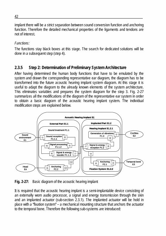
42
implant there will be a strict separation between sound conversion function and anchoring function. Therefore the detailed mechanical properties of the ligaments and tendons are not of interest. Functions:
The functions stay black boxes at this stage. The search for dedicated solutions will be done in a subsequent step (step 4).
2.3.5 Step 2: Determination of Preliminary System Architecture After having determined the human body functions that have to be emulated by the system and drawn the corresponding representative ear diagram, the diagram has to be transformed into the future acoustic hearing implant system diagram. At this stage it is useful to adapt the diagram to the already known elements of the system architecture. This eliminates variables and prepares the system diagram for the step 3. Fig. 2-27 summarizes all the modifications of the diagram of the representative ear system in order to obtain a basic diagram of the acoustic hearing implant system. The individual modification steps are explained below.
Acoustic Hearing Implant S1
External Part S1.1 Implanted Part S1.2
Soundenvironment
E1
Temporal boneE3
CochleaE2Sound reception
F1.1.1
Signal processingF1.1.2
Signal & energytransfer F1.1.3
Generation of vibrationsF1.3
Signal & energyreception F1.2
AnchoringF2.1
I1 I5
I5I6
I6 I7
I7
I8
I8
I2
AnchoringF2.2
HeadE4
I4
I4
I9
I3
Hearing Implant S1.2.1
Fixation System S1.2.2
I10
I10
Sound treatment F1.1
Fig. 2-27: Basic diagram of the acoustic hearing implant It is required that the acoustic hearing implant is a semi-implantable device consisting of an externally worn audio processor, a signal and energy transmission through the skin and an implanted actuator (sub-section 2.3.1). The implanted actuator will be hold in place with a “fixation system” – a mechanical mounting structure that anchors the actuator to the temporal bone. Therefore the following sub-systems are introduced:
43
External Part S1.1 Implanted Part S1.2
o Hearing Implant S1.2.1 o Fixation System S1.2.2
In a second step, the sound conversion function F1 has to be split in multiple serial functions in order to respect the above defined sub-systems:
Sound treatment F1.1 o Sound reception F1.1.1 o Signal processing F1.1.2 o Signal & energy transfer F1.1.3
Signal & energy reception F1.2 Generation of vibrations F1.3
The signal treatment function F1.1 is part of the external part S1.1 while F1.2 and F1.3 are parts of the implanted part S1.2. The anchoring function F2 has to be split as well. Since the temporal bone E3 is not an environment of the external part S1.1, a corresponding, new environment and anchoring function has to be introduced. The global environment head E4 takes over the role of the temporal bone E3 for the anchoring function F2.2 of the external part S1.1. It can be observed that the initial structure of the representative ear diagram is not changed. All the initial environments, interfaces and functions still exist. The global environments and their interfaces stayed unchanged beside the introduction of the new global environment E4. Things that do change are the characteristics of the interfaces towards the global environments. These interfaces are no longer body tissues but have to be transformed into technical equivalents. This will be part of the conceptual design step (step 4).
2.3.6 Step 3: Determination User and System Requirements This is a central step that determines the requirements of the acoustic hearing implant. These requirements are partially given by the already determined environments of the representative ear and are completed by introducing “artificial” environments. They cover everything that influences the system or interacts with it. They can have direct impact on the primary function of the system like the hearing loss of the patient or influence the system as a whole like the transport conditions. This design step is demonstrated by applying it only to the implantable part S1.2 of the acoustic hearing implant S1. This shows an important property of the diagram methodology, namely the possibility to isolate a sub-system or function from the complete

44
system without the risk of neglecting something important. The implanted part S1.2 and the exemplarily added artificial environments E5 to E10 are shown in Fig. 2-28. The external part S1.1 is represented as a local environment, so it is still considered.
External PartS1.1
SurgeonE6
Transportconditions
E8
PackagingE7
Storageconditions
E9
Implantconditions
E5
Implanted Part S1.2
Temporal boneE3
CochleaE2
Generation of vibrationsF1.3
Signal & energyreception F1.2
AnchoringF2.1
I7
I8
I8
I2
I4
I4 I3
Hearing Implant S1.2.1
Fixation System S1.2.2
I16
I14
I13
I12I11
Hearing lossE10
I15
Fig. 2-28: Implanted Part S1.2 with all environments
External part S1.1: It is assumed that the system electronics including the sound reception F1.1.1, the sound processing F1.1.2 and the signal & energy transfer F1.1.3 provide completely linear transfer functions as long as no individual hearing loss is programmed. This means that the output signal, which is provided by S1.1, is strictly proportional to the captured sound pressure. Therefore the provided signals correspond to Fig. 2-25 with one exception: the conventional hearing aid that serves as basis for the external part S1.1 limits the system bandwidth to 125 Hz – 8’000 Hz. The energy provided by the external part S1.1 is limited as well. The device has to operate at least one day without changing the battery. Based on the energy budget of the whole system, this entails that the output power of S1.1 is restricted to 1 mW. This results in the following requirements (user requirements are abbreviated by UR and the derived system requirements by SR):
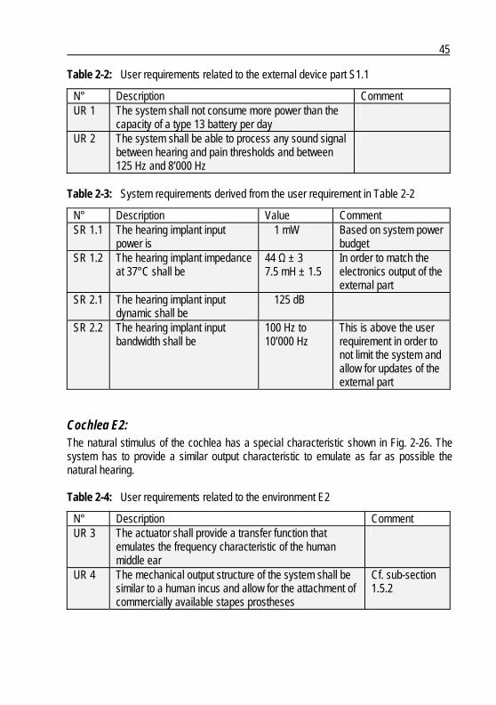
45
Table 2-2: User requirements related to the external device part S1.1
N° Description Comment UR 1 The system shall not consume more power than the
capacity of a type 13 battery per day
UR 2 The system shall be able to process any sound signal between hearing and pain thresholds and between 125 Hz and 8’000 Hz
Table 2-3: System requirements derived from the user requirement in Table 2-2
N° Description Value Comment SR 1.1 The hearing implant input
power is 1 mW Based on system power
budget SR 1.2 The hearing implant impedance
at 37°C shall be 44 Ω ± 3 7.5 mH ± 1.5
In order to match the electronics output of the external part
SR 2.1 The hearing implant input dynamic shall be
125 dB
SR 2.2 The hearing implant input bandwidth shall be
100 Hz to 10’000 Hz
This is above the user requirement in order to not limit the system and allow for updates of the external part
Cochlea E2: The natural stimulus of the cochlea has a special characteristic shown in Fig. 2-26. The system has to provide a similar output characteristic to emulate as far as possible the natural hearing. Table 2-4: User requirements related to the environment E2
N° Description Comment UR 3 The actuator shall provide a transfer function that
emulates the frequency characteristic of the human middle ear
UR 4 The mechanical output structure of the system shall be similar to a human incus and allow for the attachment of commercially available stapes prostheses
Cf. sub-section 1.5.2
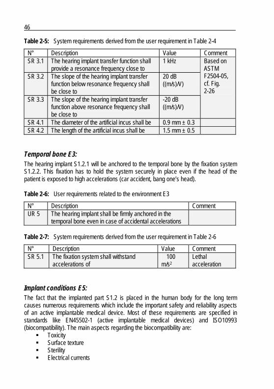
46
Table 2-5: System requirements derived from the user requirement in Table 2-4
N° Description Value Comment SR 3.1 The hearing implant transfer function shall
provide a resonance frequency close to 1 kHz
SR 3.2 The slope of the hearing implant transfer function below resonance frequency shall be close to
20 dB ((m/s)/V)
SR 3.3 The slope of the hearing implant transfer function above resonance frequency shall be close to
-20 dB ((m/s)/V)
Based on ASTM F2504-05, cf. Fig. 2-26
SR 4.1 The diameter of the artificial incus shall be 0.9 mm ± 0.3 SR 4.2 The length of the artificial incus shall be 1.5 mm ± 0.5
Temporal bone E3: The hearing implant S1.2.1 will be anchored to the temporal bone by the fixation system S1.2.2. This fixation has to hold the system securely in place even if the head of the patient is exposed to high accelerations (car accident, bang one’s head). Table 2-6: User requirements related to the environment E3
N° Description Comment UR 5 The hearing implant shall be firmly anchored in the
temporal bone even in case of accidental accelerations
Table 2-7: System requirements derived from the user requirement in Table 2-6
N° Description Value Comment SR 5.1 The fixation system shall withstand
accelerations of 100
m/s2 Lethal acceleration
Implant conditions E5: The fact that the implanted part S1.2 is placed in the human body for the long term causes numerous requirements which include the important safety and reliability aspects of an active implantable medical device. Most of these requirements are specified in standards like EN45502-1 (active implantable medical devices) and ISO10993 (biocompatibility). The main aspects regarding the biocompatibility are:
Toxicity Surface texture Sterility Electrical currents
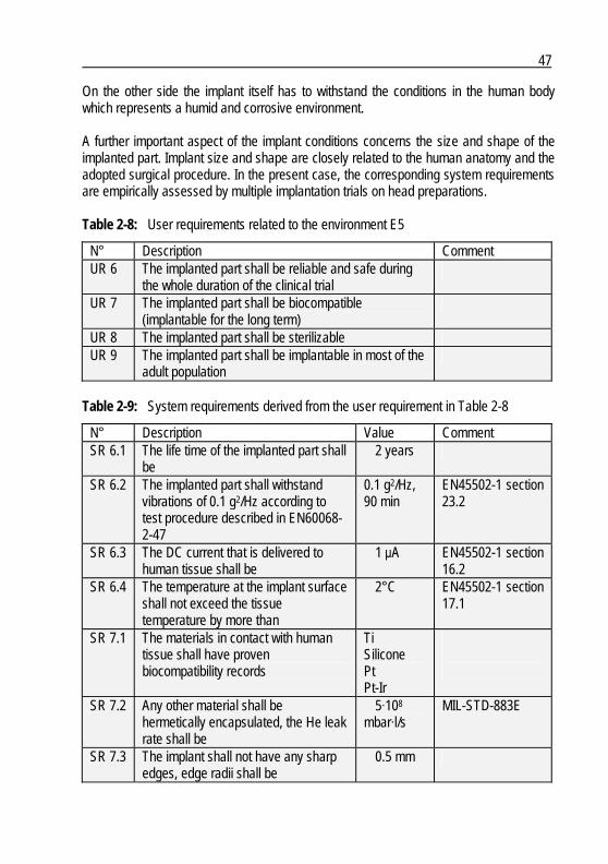
47
On the other side the implant itself has to withstand the conditions in the human body which represents a humid and corrosive environment. A further important aspect of the implant conditions concerns the size and shape of the implanted part. Implant size and shape are closely related to the human anatomy and the adopted surgical procedure. In the present case, the corresponding system requirements are empirically assessed by multiple implantation trials on head preparations. Table 2-8: User requirements related to the environment E5
N° Description Comment UR 6 The implanted part shall be reliable and safe during
the whole duration of the clinical trial
UR 7 The implanted part shall be biocompatible (implantable for the long term)
UR 8 The implanted part shall be sterilizable UR 9 The implanted part shall be implantable in most of the
adult population
Table 2-9: System requirements derived from the user requirement in Table 2-8
N° Description Value Comment SR 6.1 The life time of the implanted part shall
be 2 years
SR 6.2 The implanted part shall withstand vibrations of 0.1 g2/Hz according to test procedure described in EN60068-2-47
0.1 g2/Hz, 90 min
EN45502-1 section 23.2
SR 6.3 The DC current that is delivered to human tissue shall be
1 μA EN45502-1 section 16.2
SR 6.4 The temperature at the implant surface shall not exceed the tissue temperature by more than
2°C EN45502-1 section 17.1
SR 7.1 The materials in contact with human tissue shall have proven biocompatibility records
Ti Silicone Pt Pt-Ir
SR 7.2 Any other material shall be hermetically encapsulated, the He leak rate shall be
5·108 mbar·l/s
MIL-STD-883E
SR 7.3 The implant shall not have any sharp edges, edge radii shall be
0.5 mm
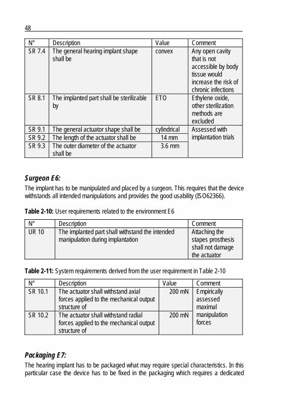
48
N° Description Value Comment SR 7.4 The general hearing implant shape
shall be convex Any open cavity
that is not accessible by body tissue would increase the risk of chronic infections
SR 8.1 The implanted part shall be sterilizable by
ETO Ethylene oxide, other sterilization methods are excluded
SR 9.1 The general actuator shape shall be cylindrical SR 9.2 The length of the actuator shall be 14 mm SR 9.3 The outer diameter of the actuator
shall be 3.6 mm
Assessed with implantation trials
Surgeon E6: The implant has to be manipulated and placed by a surgeon. This requires that the device withstands all intended manipulations and provides the good usability (ISO62366). Table 2-10: User requirements related to the environment E6
N° Description Comment UR 10 The implanted part shall withstand the intended
manipulation during implantation Attaching the stapes prosthesis shall not damage the actuator
Table 2-11: System requirements derived from the user requirement in Table 2-10
N° Description Value Comment SR 10.1 The actuator shall withstand axial
forces applied to the mechanical output structure of
200 mN
SR 10.2 The actuator shall withstand radial forces applied to the mechanical output structure of
200 mN
Empirically assessed maximal manipulation forces
Packaging E7: The hearing implant has to be packaged what may require special characteristics. In this particular case the device has to be fixed in the packaging which requires a dedicated
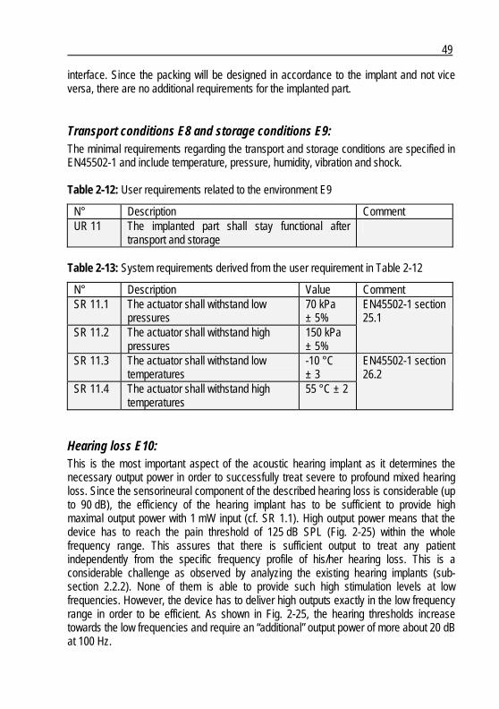
49
interface. Since the packing will be designed in accordance to the implant and not vice versa, there are no additional requirements for the implanted part.
Transport conditions E8 and storage conditions E9: The minimal requirements regarding the transport and storage conditions are specified in EN45502-1 and include temperature, pressure, humidity, vibration and shock. Table 2-12: User requirements related to the environment E9
N° Description Comment UR 11 The implanted part shall stay functional after
transport and storage
Table 2-13: System requirements derived from the user requirement in Table 2-12
N° Description Value Comment SR 11.1 The actuator shall withstand low
pressures 70 kPa ± 5%
SR 11.2 The actuator shall withstand high pressures
150 kPa ± 5%
EN45502-1 section 25.1
SR 11.3 The actuator shall withstand low temperatures
-10 °C ± 3
SR 11.4 The actuator shall withstand high temperatures
55 °C ± 2
EN45502-1 section 26.2
Hearing loss E10: This is the most important aspect of the acoustic hearing implant as it determines the necessary output power in order to successfully treat severe to profound mixed hearing loss. Since the sensorineural component of the described hearing loss is considerable (up to 90 dB), the efficiency of the hearing implant has to be sufficient to provide high maximal output power with 1 mW input (cf. SR 1.1). High output power means that the device has to reach the pain threshold of 125 dB SPL (Fig. 2-25) within the whole frequency range. This assures that there is sufficient output to treat any patient independently from the specific frequency profile of his/her hearing loss. This is a considerable challenge as observed by analyzing the existing hearing implants (sub-section 2.2.2). None of them is able to provide such high stimulation levels at low frequencies. However, the device has to deliver high outputs exactly in the low frequency range in order to be efficient. As shown in Fig. 2-25, the hearing thresholds increase towards the low frequencies and require an “additional” output power of more about 20 dB at 100 Hz.

50
Table 2-14: User requirements related to the environment E10
N° Description Comment UR 12 The hearing implant shall provided sufficient output
power to successfully treat patients with severe to profound mixed hearing loss
Table 2-15: System requirements derived from the user requirement in Table 2-14
N° Description Value Comment SR 12.1 The hearing implant output bandwidth
shall be 100 Hz to 10’000 Hz
SR 12.2 The hearing implant output power shall be equivalent to
125 dB SPL
With 1 mW input power (SR )
2.3.7 Step 4: Conceptual Design In principle the system is fully determined in step 3, and one can start searching for solutions for the individual functions. However, it is possible to first modify the system diagram in order to simplify the search for solutions process. This is demonstrated using the generation of vibrations function F1.3. Since the actual search for solutions process is outside the scope of this work, it is only presented for exemplary purpose. Any other search for solutions method like brainstorming, literature search, design catalogues or Triz can be applied as well. Here, it shall be established how the system diagram can support and guide the search for process. The function F1.3 is isolated from the remaining system as shown in Fig. 2-29. A preliminary evaluation of the influence of the different environments is done to simplify the task. The goal is to temporarily neglect environments that do not influence significantly the solution of the function. Of course, the assumption that the influence is not significant has to be verified once a solution is found. In the concrete case, the global environments E6 to E9 and the local environment S1.2.2 are put aside. From the considered ones, the biocompatibility aspect of the implant condition environment causes difficulties to find a solution. Therefore it is proposed to first decouple the function F1.3 from the environment E5 by adding a hermetic housing function F1.4 as shown in Fig. 2-30. Further modifications of the system diagram are the introduction of the stapes prosthesis environment E11 and the artificial incus function F1.5. This last two modifications account for the fact that a stapes prosthesis is used to couple the vibrations to the cochlea (sub-section 1.5.2). As a general approach it is proposed to always proceed from the defined towards the undefined. This guaranties that already determined system elements are considered and prevents the development of incompatible solutions. Therefore following sequence is proposed:

51
SurgeonE6
Transportconditions
E8
PackagingE7
Storageconditions
E9
Implantconditions
E5
CochleaE2
Generation of vibrationsF1.3I8 I2
I4
Fixation SystemS1.2.2
I16
I14I13
I12I11
Signal & energyreception F1.4
Hearing lossE10
I15
SurgeonE6
Transportconditions
E8
PackagingE7
Storageconditions
E9
Implantconditions
E5
CochleaE2
Generation of vibrationsF1.3I8 I2
I4
Fixation SystemS1.2.2
I16
I14I13
I12I11
Signal & energyreception F1.4
Hearing lossE10
I15
Fig. 2-29: Isolated generation of vibrations function F1.3 with its local and global environments, the elements that have to be considered further on are gray shaded, the white ones can currently be neglected
Hermitic housingF1.4
Implantconditions
E5
CochleaE2
Generation of vibrationsF1.3
I8
I16
Signal & energyreception F1.4
Artificial incusF1.5
Stapesprosthesis
E11I18I17
I8 I17
Hearing lossE10
I15
I19
Hermitic housingF1.4
Implantconditions
E5
CochleaE2
Generation of vibrationsF1.3
I8
I16
Signal & energyreception F1.4
Artificial incusF1.5
Stapesprosthesis
E11I18I17
I8 I17
Hearing lossE10
I15
I19
Fig. 2-30: Generation of vibrations function F1.3 that is decoupled from the implant conditions environment E5 by the added hermetic housing function F1.4
Artificial incus function F1.5: The mechanical output structure of the actuator has to provide a geometry similar to the long process of incus (SR 4.1and SR 4.2) in order to allow the attachment of a stapes prosthesis (I18).
52
Hermetic housing function F1.4: In order to meet the requirements coming from the implant condition environment E5, the actuator has to be encapsulated in a hermetic housing with the following characteristics:
It has to consist of biocompatible materials (SR 7.1) It has to be of cylindrical shape (SR 9.1) Its maximal length is 14 mm (SR 9.2) Its maximal diameter is 3.6 mm (SR 9.3)
The electrical power (I8) and the generated vibration (I17) have to pass through the housing wall without causing leakage (SR 7.2). Thus one face side of the housing cylinder is closed with a hermetic feedthrough in order to pass the electrical connection. The other face side has to be closed with a compliant element that allows moving the artificial incus.
Generation of vibrations function F1.3: Now everything is prepared to search for the key function F1.3 of the acoustic hearing implant system S1. Before starting the search it is useful to summarize the determined interface characteristics: I8 A maximal power of 1 mW will be provided to the actuator (SR 1.1).
I15 The actuator has to provide a maximal equivalent sound pressure of 125 dB (SR 2.1).
I17 The output spectrum of the actuator has to be similar to the normalized transfer function of the middle ear (SR 3.1, SR 3.2 and SR 3.3, Fig. 2-32a). Therefore the spring constant of the compliant housing face side I17 and the mass of the artificial incus F1.5 as well as the mass of the stapes prosthesis E11 have to be taken into account for the calculations.
The normalized middle ear transfer function corresponds in first approximation to a second-order low-pass filter with a cutoff frequency of about 1 kHz (Fig. 2-26). From a mechanical perspective, this corresponds to the oscillation characteristic of a suspended mass (Fig. 2-32b), which defines the first three important parameters of the actuator:
the mobile mass m, the spring constant k, and the resonance frequency fres which is defined as follows:
mk
fres π21= (1)
Since the goal resonance frequency is 1 kHz (SR 3.1), there is one degree of freedom left for the mass and the spring constant. To have an idea of the order of magnitude of these two parameters, the human middle ear can give a first indication. The mass of the three
53
ossicles of about 65 mg [46] results in a spring constant of approximately 2.5 N/mm using (1). Considering the fact that the actuator deflection should be maximized while minimizing the energy consumption, the mobile mass has to be as low as possible. In first approximation, the mobile mass consists of the stapes prosthesis and the artificial incus (Fig. 2-32c). The mass of an ordinary stapes prosthesis is about 3 mg. The mass of the artificial incus can be preliminarily assessed by considering its dimensions (SR 4.1 and SR 4.2) and the specific mass of titanium (SR 7.1) of 4.5 g/cm3. This results in an artificial incus mass of 4.2 mg. The sum of 7.2 mg is far below the mass of the three ossicles what is promising in regard to the actuator efficiency. The potential of this low mobile mass can only be exploited if the spring constant is much lower than that of the middle ear. If not, the mass has to be artificially increased to keep the resonance frequency at 1 kHz. At this stage, the compliant face side of the actuator housing I17 has to be examined in more detail. The preferred and simplest solution would be a flat diaphragm. Such a diaphragm would act as a spring and, therefore, suit the basic concept of a suspended mass if the spring constant of the diaphragm is within an acceptable range. The spring constant of a circular diaphragm, kD, with a rigid center (Fig. 2-31) is given by the following formula [47]:
⎟⎟⎟⎟⎟
⎠
⎞
⎜⎜⎜⎜⎜
⎝
⎛
−⎟⎠⎞
⎜⎝⎛
⎟⎠⎞
⎜⎝⎛
−
⎟⎠⎞
⎜⎝⎛
−⎟⎠⎞
⎜⎝⎛
−
=
1
ln
4
1)1(3
2 2
2
2
2
3
idod
idod
idod
idod
od
thEk
Ti
TiD
πν
(2)
Where: od 3.6 mm (maximal actuator diameter)
id 1.0 mm (estimated diameter of the actuator shaft) th 25 μm (minimal thickness to allow reliable laser welding) ETi 116 GPa (Young’s modulus of titanium) νTi 0.34 (Poisson coefficient of titanium)
The spring constant calculated with the above parameters is 6.9 N/mm, which is higher than the 2.5 N/mm of the middle ear. This would lead to a shift of the frequency response if the small mobile mass of 7.2 mg is taken into account (Fig. 2-32d).
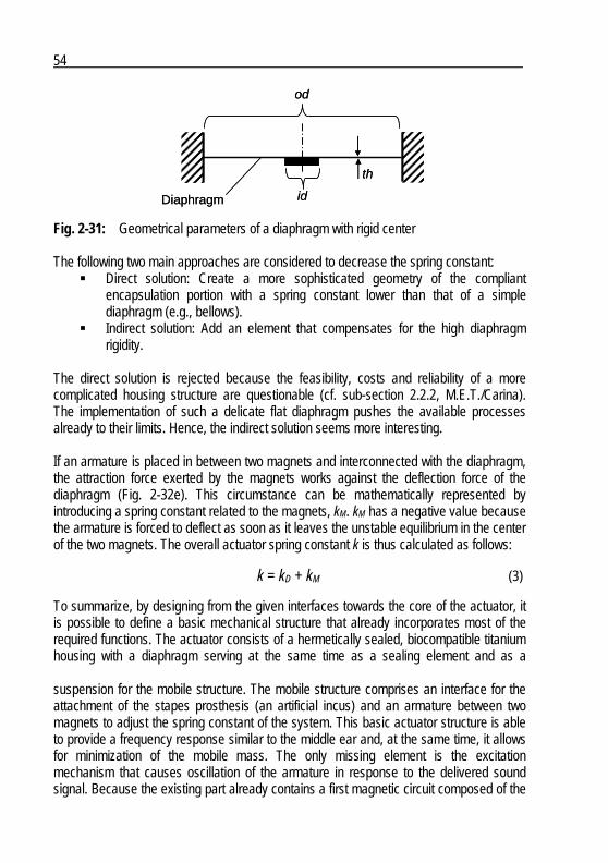
54
od
id
th
Diaphragm
od
id
th
Diaphragm
Fig. 2-31: Geometrical parameters of a diaphragm with rigid center The following two main approaches are considered to decrease the spring constant:
Direct solution: Create a more sophisticated geometry of the compliant encapsulation portion with a spring constant lower than that of a simple diaphragm (e.g., bellows).
Indirect solution: Add an element that compensates for the high diaphragm rigidity.
The direct solution is rejected because the feasibility, costs and reliability of a more complicated housing structure are questionable (cf. sub-section 2.2.2, M.E.T./Carina). The implementation of such a delicate flat diaphragm pushes the available processes already to their limits. Hence, the indirect solution seems more interesting. If an armature is placed in between two magnets and interconnected with the diaphragm, the attraction force exerted by the magnets works against the deflection force of the diaphragm (Fig. 2-32e). This circumstance can be mathematically represented by introducing a spring constant related to the magnets, kM. kM has a negative value because the armature is forced to deflect as soon as it leaves the unstable equilibrium in the center of the two magnets. The overall actuator spring constant k is thus calculated as follows:
k = kD + kM (3) To summarize, by designing from the given interfaces towards the core of the actuator, it is possible to define a basic mechanical structure that already incorporates most of the required functions. The actuator consists of a hermetically sealed, biocompatible titanium housing with a diaphragm serving at the same time as a sealing element and as a suspension for the mobile structure. The mobile structure comprises an interface for the attachment of the stapes prosthesis (an artificial incus) and an armature between two magnets to adjust the spring constant of the system. This basic actuator structure is able to provide a frequency response similar to the middle ear and, at the same time, it allows for minimization of the mobile mass. The only missing element is the excitation mechanism that causes oscillation of the armature in response to the delivered sound signal. Because the existing part already contains a first magnetic circuit composed of the

55
magnets and the armature, a coil was added to modulate the magnetic flux in order to vibrate the armature (Fig. 2-32f).
f1 kHz
v
f1 kHz
v
f1 kHz
v
f1 kHz
v
f1 kHz
v
f1 kHz
v
a) b) c) d) e) f)
mk
f1 kHz
v
f1 kHz
v
f1 kHz
v
f1 kHz
v
f1 kHz
v
f1 kHz
v
f1 kHz
v
f1 kHz
v
f1 kHz
v
f1 kHz
v
f1 kHz
v
f1 kHz
v
a) b) c) d) e) f)
mk
Fig. 2-32: Search for solution process for the generation of vibrations function F1.3: a) schematic middle ear with its frequency response, b) corresponding mechanical structure: suspended mass, c) the actuator coupling structure, artificial incus and stapes prosthesis represent the mass, d) the housing with a diaphragm playing the role of the spring is added; due to the high spring constant, the transfer function is shifted, e) the added magnets and armature compensate for the high diaphragm rigidity and correct the transfer function and f) a coil is added to excite the armature
The result is a dedicated implementation of the balanced armature actuator principle. The fact that balanced armature actuators are used for highly efficient, miniaturized hearing aid loudspeakers confirms that the proposed principle should be well suited for acoustic applications. Fig. 2-33 shows a schematic representation of all active actuator elements that represent the solution for function F1.3.
Coil
Magnets
Armature
Soft magnetic sleeve
Coil
Magnets
Armature
Soft magnetic sleeve
Fig. 2-33: Schematic representation of the solution for the generation of vibrations function F1.3 comprising two ring magnets (the arrows indicate their
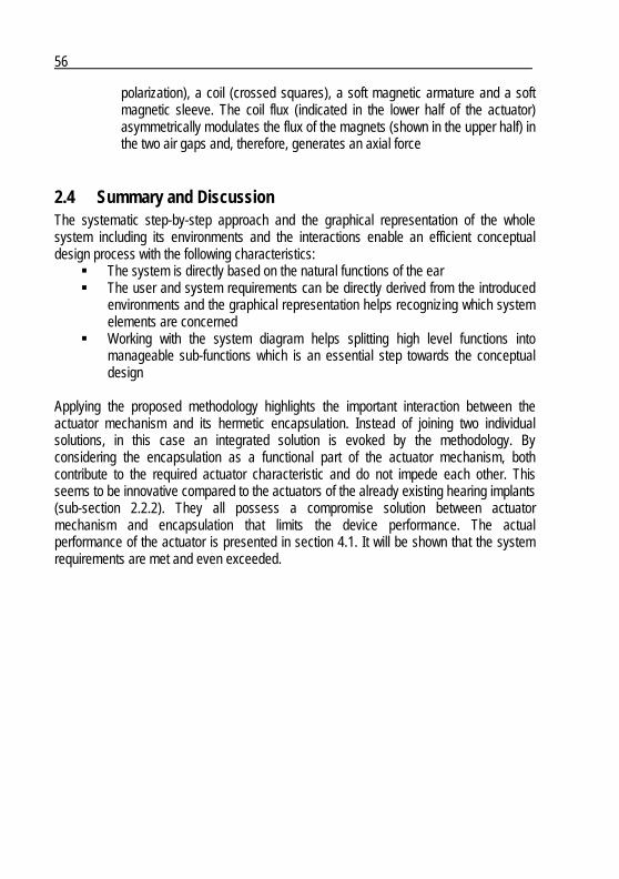
56
polarization), a coil (crossed squares), a soft magnetic armature and a soft magnetic sleeve. The coil flux (indicated in the lower half of the actuator) asymmetrically modulates the flux of the magnets (shown in the upper half) in the two air gaps and, therefore, generates an axial force
2.4 Summary and Discussion The systematic step-by-step approach and the graphical representation of the whole system including its environments and the interactions enable an efficient conceptual design process with the following characteristics:
The system is directly based on the natural functions of the ear The user and system requirements can be directly derived from the introduced
environments and the graphical representation helps recognizing which system elements are concerned
Working with the system diagram helps splitting high level functions into manageable sub-functions which is an essential step towards the conceptual design
Applying the proposed methodology highlights the important interaction between the actuator mechanism and its hermetic encapsulation. Instead of joining two individual solutions, in this case an integrated solution is evoked by the methodology. By considering the encapsulation as a functional part of the actuator mechanism, both contribute to the required actuator characteristic and do not impede each other. This seems to be innovative compared to the actuators of the already existing hearing implants (sub-section 2.2.2). They all possess a compromise solution between actuator mechanism and encapsulation that limits the device performance. The actual performance of the actuator is presented in section 4.1. It will be shown that the system requirements are met and even exceeded.
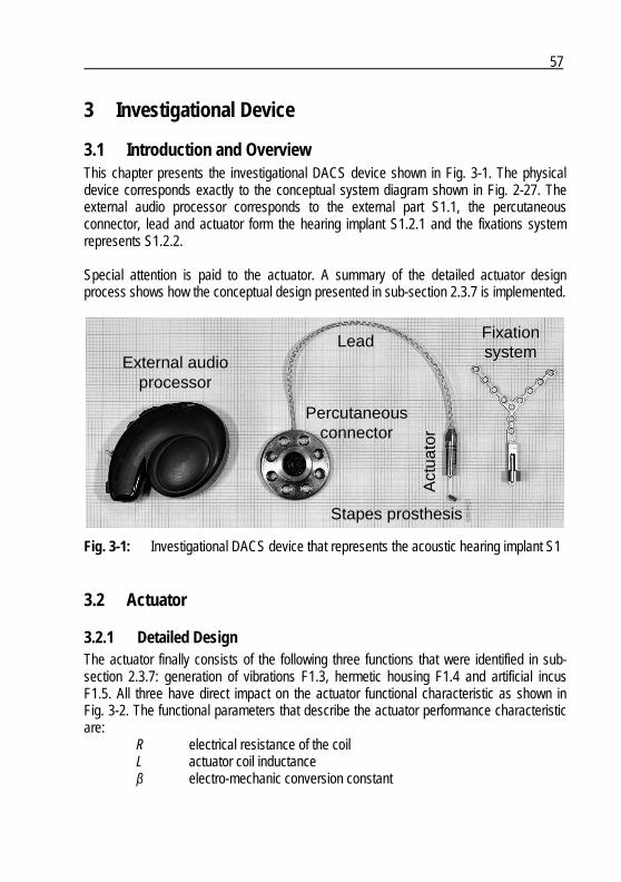
57
3 Investigational Device
3.1 Introduction and Overview This chapter presents the investigational DACS device shown in Fig. 3-1. The physical device corresponds exactly to the conceptual system diagram shown in Fig. 2-27. The external audio processor corresponds to the external part S1.1, the percutaneous connector, lead and actuator form the hearing implant S1.2.1 and the fixations system represents S1.2.2. Special attention is paid to the actuator. A summary of the detailed actuator design process shows how the conceptual design presented in sub-section 2.3.7 is implemented.
External audioprocessor
Percutaneousconnector
Fixationsystem
Act
uato
r
Lead
Stapes prosthesis
External audioprocessor
Percutaneousconnector
Fixationsystem
Act
uato
r
Lead
Stapes prosthesis
Fig. 3-1: Investigational DACS device that represents the acoustic hearing implant S1
3.2 Actuator
3.2.1 Detailed Design The actuator finally consists of the following three functions that were identified in sub-section 2.3.7: generation of vibrations F1.3, hermetic housing F1.4 and artificial incus F1.5. All three have direct impact on the actuator functional characteristic as shown in Fig. 3-2. The functional parameters that describe the actuator performance characteristic are:
R electrical resistance of the coil L actuator coil inductance β electro-mechanic conversion constant
58
m mobile actuator mass including the armature, the actuator shaft, the artificial incus and the stapes prosthesis (the mass of the diaphragm is sufficiently small to be neglected)
kD diaphragm spring constant kM negative spring constant representing the attraction force of the
magnets c actuator damping coefficient cL mechanical impedance of the cochlea (represents the actuator load)
Coil: R, L
Diaphragm: kD
Generation of vibrations F1.3 Diaphragm I17Artificial
incus F1.5
Mobile mass: m
Attraction force of magnets: kM
Electro-mechanicconversion constant: β
Dampingcoefficient: c
Stapesprosthesis E10 Cochlea E2
Mechanical impedanceof the cochlea: cL
Hermetic housing F1.4
Feed-through I8
Fig. 3-2: Actuator functions, corresponding concepts, relevant environments and resulting functional parameters
The diaphragm I17 plays a key role regarding the integration of the different actuator functions. It is at the same time part of the hermetic housing F1.4, defines the frequency response of the generation of vibration function F1.3 and provides radial guidance of the actuator shaft. The next step is to set up models that link the identified functional parameters to the performance characteristics of the actuator. These models have to be as simple as possible and as accurate as necessary in order to minimize development efforts. Therefore it is decided to work with the following two main models:
A lumped parameter model directly derived from the basic actuator structure in Fig. 3-2 which simulates the frequency response of the actuator
A static finite element model to simulate the magnetic circuits and to calculate the electro-mechanic conversion constant β as well as the attraction force of the magnets, represented by kM
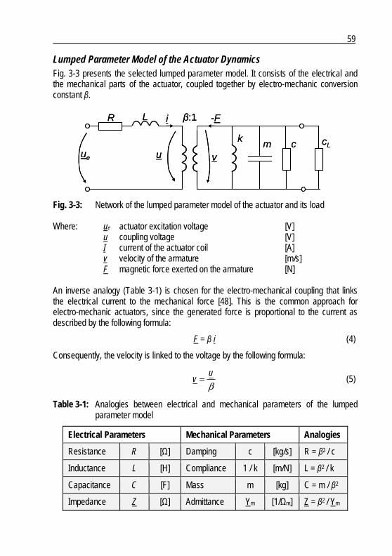
59
Lumped Parameter Model of the Actuator Dynamics Fig. 3-3 presents the selected lumped parameter model. It consists of the electrical and the mechanical parts of the actuator, coupled together by electro-mechanic conversion constant β.
ue
i -F
v
R L
cmk cL
β:1
uue
i -F
v
R L
cmk cL
β:1
u
Fig. 3-3: Network of the lumped parameter model of the actuator and its load Where: ue actuator excitation voltage [V]
u coupling voltage [V] I current of the actuator coil [A] v velocity of the armature [m/s] F magnetic force exerted on the armature [N]
An inverse analogy (Table 3-1) is chosen for the electro-mechanical coupling that links the electrical current to the mechanical force [48]. This is the common approach for electro-mechanic actuators, since the generated force is proportional to the current as described by the following formula:
F = β i (4)
Consequently, the velocity is linked to the voltage by the following formula:
βu
v = (5)
Table 3-1: Analogies between electrical and mechanical parameters of the lumped parameter model
Electrical Parameters Mechanical Parameters Analogies
Resistance R [Ω] Damping c [kg/s] R = β2 / c
Inductance L [H] Compliance 1 / k [m/N] L = β2 / k
Capacitance C [F] Mass m [kg] C = m / β2
Impedance Z [Ω] Admittance Ym [1/Ωm] Z = β2 / Ym
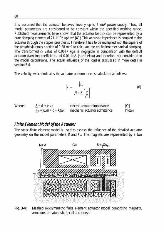
60
It is assumed that the actuator behaves linearly up to 1 mW power supply. Thus, all model parameters are considered to be constant within the specified working range. Published measurements have shown that the actuator load cL can be represented by a pure damping element of 21.1·109 kg/s·m4 [49]. This acoustic impedance is coupled to the actuator through the stapes prosthesis. Therefore it has to be multiplied with the square of the prosthesis cross section of 0.28 mm2 to calculate the equivalent mechanical damping. The transformed cL value of 0.0017 kg/s is negligible in comparison with the default actuator damping coefficient c of 0.01 kg/s (see below) and therefore not considered in the model calculations. The actual influence of the load is discussed in more detail in section 5.4. The velocity, which indicates the actuator performance, is calculated as follows:
ββ m
e
YZ
uv
+= (6)
Where: Z = R + jωL: electric actuator impedance [Ω]
Ym = jωm + c + k/jω: mechanic actuator admittance [1/Ωm]
Finite Element Model of the Actuator The static finite element model is used to assess the influence of the detailed actuator geometry on the model parameters β and kM. The magnets are represented by a two
Cu Sm2Co17NiFe Cu Sm2Co17NiFe
Fig. 3-4: Meshed axi-symmetric finite element actuator model comprising magnets, armature, armature shaft, coil and sleeve
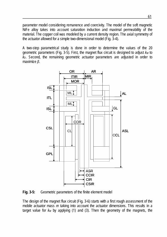
61
parameter model considering remanence and coercivity. The model of the soft magnetic NiFe alloy takes into account saturation induction and maximal permeability of the material. The copper coil was modeled by a current density region. The axial symmetry of the actuator allowed for a simple two-dimensional model (Fig. 3-4). A two-step parametrical study is done in order to determine the values of the 20 geometric parameters (Fig. 3-5). First, the magnet flux circuit is designed to adjust kM to kD. Second, the remaining geometric actuator parameters are adjusted in order to maximize β.
CL
ISL
ITL
ISL
CSL
GPL
ML
ML
AL
ASL
OR
ITIRMOR
ARMIR
ASRCCIRCIR
COR
CSIR
CCL
GL
CL
ISL
ITL
ISL
CSL
GPL
ML
ML
AL
ASL
OR
ITIRMOR
ARMIR
ASRCCIRCIR
COR
CSIR
CCL
GL
Fig. 3-5: Geometric parameters of the finite element model The design of the magnet flux circuit (Fig. 3-6) starts with a first rough assessment of the mobile actuator mass m taking into account the actuator dimensions. This results in a target value for kM by applying (1) and (3). Then the geometry of the magnets, the

62
surrounding nickel iron structure and the armature are manually adjusted in order to reach the target value of kM while respecting the following design rules:
The distance between armature and the magnets has to be at least 0.1 mm in order to respect part and assembly tolerances
The thickness of the magnets has to be at least 0.3 mm in order to respect fabrication limits
The flux density of the surrounding soft magnetic structure has to stay below the saturation value of the material (Fig. 3-7)
The value of kM has to stay constant within the deflection range of the actuator of +/- 0.015 mm (Fig. 3-8)
Fig. 3-6: Magnet flux lines (no coil current)
Fig. 3-7: Magnet flux density plot of the longitudinal actuator section (no coil current)

63
Force Exerted on the Armature
-500
-400
-300
-200
-100
0
100
200
300
400
500
-0.08 -0.06 -0.04 -0.02 0 0.02 0.04 0.06 0.08
Armature deflection [mm]
Fo
rce
[arb
itra
ry u
nit
s]
v
Force Exerted on the Armature
-500
-400
-300
-200
-100
0
100
200
300
400
500
-0.08 -0.06 -0.04 -0.02 0 0.02 0.04 0.06 0.08
Armature deflection [mm]
Fo
rce
[arb
itra
ry u
nit
s]
v
Fig. 3-8: The slope of the force curve that corresponds to kM is very constant within the intended actuator deflection range of ± 0.015 mm (shaded range)
kM is assessed by translating the armature and its shaft in the axial direction and calculating the force between the mobile and the static part of the actuator. Eventually the dynamic actuator characteristics are fine-tuned by adjusting the thickness of the armature (AL) in order to achieve a resonance frequency of about 1 kHz according to (1). The resulting lumped model parameters values are:
m = 35 mg kM = -5.9 N/mm
The determination of the remaining geometric parameters specifying the coil and the soft magnetic structure (Fig. 3-9) is done manually as well. The main goal is to maximize β and therefore the efficiency of the actuator. The additional design rules and guidelines, that have to be respected, are:
The reluctance of the radial air gap between armature shaft and the actuator sleeve has to be minimized while keeping a minimal distance of 0.1 mm in order to consider reasonable part and assembly tolerances
The flux density of all soft magnetic parts has to stay below saturation when a current equivalent to 1 mW input power is applied
The maximal length of the actuation mechanism has to stay below 8 mm. (The remaining 6 mm of the total actuator length of 14 mm were used for the feedthrough and the connection of the lead.)
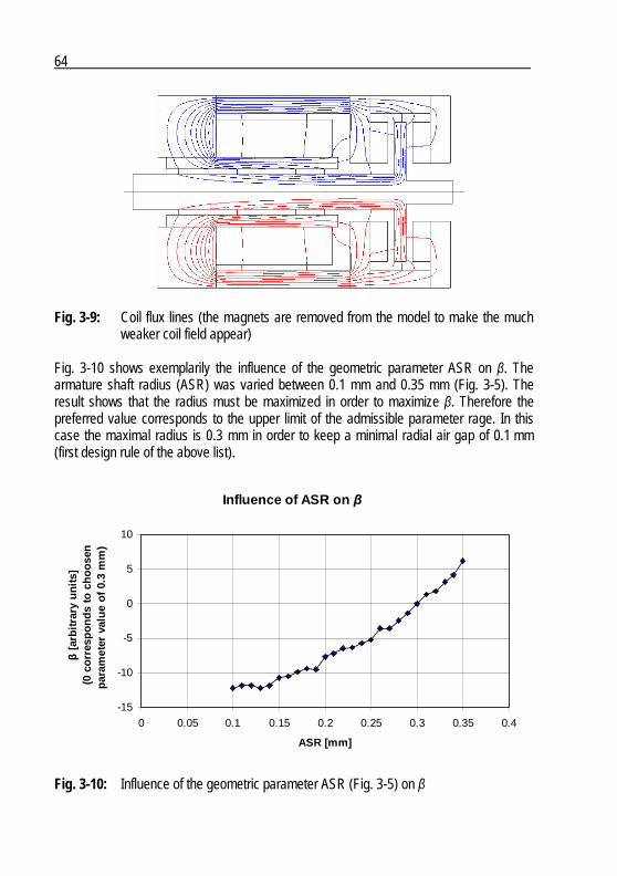
64
Fig. 3-9: Coil flux lines (the magnets are removed from the model to make the much weaker coil field appear)
Fig. 3-10 shows exemplarily the influence of the geometric parameter ASR on β. The armature shaft radius (ASR) was varied between 0.1 mm and 0.35 mm (Fig. 3-5). The result shows that the radius must be maximized in order to maximize β. Therefore the preferred value corresponds to the upper limit of the admissible parameter rage. In this case the maximal radius is 0.3 mm in order to keep a minimal radial air gap of 0.1 mm (first design rule of the above list).
Influence of ASR on β
-15
-10
-5
0
5
10
0 0.05 0.1 0.15 0.2 0.25 0.3 0.35 0.4
ASR [mm]
β [a
rbit
rary
un
its]
(0 c
orr
esp
on
ds
to c
ho
ose
n
par
amet
er v
alu
e o
f 0.
3 m
m)
Fig. 3-10: Influence of the geometric parameter ASR (Fig. 3-5) on β

65
β was assessed by calculating the force between the mobile and the static part of the actuator in function of the applied current. The resulting value of β is:
β = 2.25 N/A
Remaining Lumped Model Parameters and Simulated Actuator Performance An initial actuator-damping coefficient c is determined based on preliminary diaphragm characterization. The spring constant and the damping coefficient are assessed by measuring the frequency response when a known mass is attached in the center of the diaphragm. Thereto the diaphragm is clamped on its circumference and mounted on a shaker. The frequency response is measured using laser Doppler vibrometry (PSV 200, Polytec GmbH, Waldbronn, Germany). Then the damping coefficient is determined by fitting the height of the resonance peak with measurements of the frequency response and the final value is obtained:
c = 0.01 kg/s Resistance R and inductance L of the actuator are not limited by the actuator design itself. In fact, the electronic driver of the actuator imposes their values, which can be adjusted by varying the coil wire diameter (only for R) and the number of turns. In order to reach 1 mW of power consumption when the maximal driver voltage is applied, their values are set to:
R = 12 Ω (the difference to the specified value of 44 Ω (SR 1.2) is due to the resistance of the lead of 32 Ω that has to be subtracted from the required value in order to determine the coil resistance R)
L = 7.5 mH Having defined all parameters of the lumped parameter model, it is possible to verify if the actuator theoretically meets the main requirement, namely, if it achieves an equivalent of 125 dB SPL with 1 mW of input power. For that purpose it is necessary to convert sound pressure into velocity of a stapes prosthesis vibrating in the cochlea. The basis of this conversion is the normalized middle ear transfer function specified in ASTM-2504 (Fig. 2-26). It defines the stapes velocity corresponding to a sound pressure of 1 Pa (94 dB SPL) in front of the tympanic membrane at discrete frequencies from 125 Hz to 6’000 Hz. Because, in this case, the stapes is replaced by a prosthesis, it is important to take the reduced active section into account. Considering a midsized stapes prosthesis with a diameter of 0.6 mm and an average stapes footplate area of 3.2 mm2, the required velocity is eleven times higher than the velocity of the normal stapes. Fig. 3-11 shows the promising result. Based on these simulations, the actuator should be able to meet the required performance.
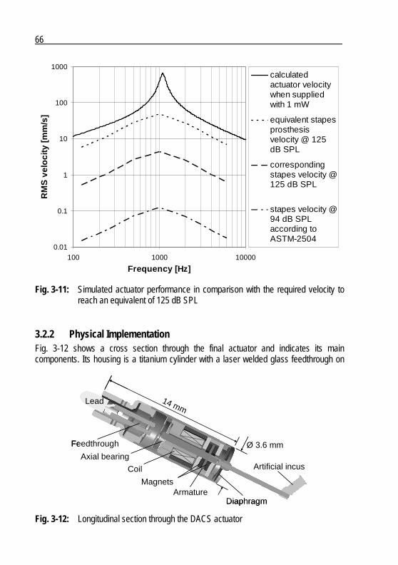
66
0.01
0.1
1
10
100
1000
100 1000 10000
Frequency [Hz]
RM
S v
elo
city
[mm
/s]
calculatedactuator velocitywhen suppliedwith 1 mW
equivalent stapesprosthesisvelocity @ 125dB SPL
correspondingstapes velocity @125 dB SPL
stapes velocity @94 dB SPLaccording toASTM-2504
Fig. 3-11: Simulated actuator performance in comparison with the required velocity to reach an equivalent of 125 dB SPL
3.2.2 Physical Implementation Fig. 3-12 shows a cross section through the final actuator and indicates its main components. Its housing is a titanium cylinder with a laser welded glass feedthrough on
Armature
Lead
Feedthrough
Magnets
Coil Artificial incus
Diaphragm
14 mm
Ø 3.6 mmAxial bearing
Armature
Lead
Feedthrough
Magnets
Coil Artificial incus
Diaphragm
14 mm
Ø 3.6 mmAxial bearing
Fig. 3-12: Longitudinal section through the DACS actuator
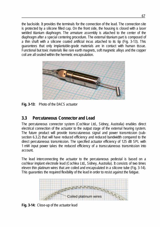
67
the backside. It provides the terminals for the connection of the lead. The connection site is protected by a silicone filled cap. On the front side, the housing is closed with a laser welded titanium diaphragm. The armature assembly is attached to the center of the diaphragm after a special centering procedure. The external titanium part is composed of a thin shaft with a silicone coated artificial incus attached to its tip (Fig. 3-13). This guarantees that only implantable-grade materials are in contact with human tissue. Functional but toxic materials like rare earth magnets, soft magnetic alloys and the copper coil are all sealed within the hermetic encapsulation.
Fig. 3-13: Photo of the DACS actuator
3.3 Percutaneous Connector and Lead The percutaneous connector system (Cochlear Ltd., Sidney, Australia) enables direct electrical connection of the actuator to the output stage of the external hearing system. The future product will provide transcutaneous signal and power transmission (sub-section 6.3.2) that will have reduced efficiency and reduced bandwidth compared to the direct percutaneous transmission. The specified actuator efficiency of 125 dB SPL with 1 mW input power takes the reduced efficiency of a transcutaneous transmission into account. The lead interconnecting the actuator to the percutaneous pedestal is based on a cochlear implant electrode lead (Cochlea Ltd., Sidney, Australia). It consists of two times eleven thin platinum wires that are coiled and encapsulated in a silicone tube (Fig. 3-14). This guaranties the required flexibility of the lead in order to resist against the fatigue.
Coiled platinum wiresCoiled platinum wires
Fig. 3-14: Close-up of the actuator lead
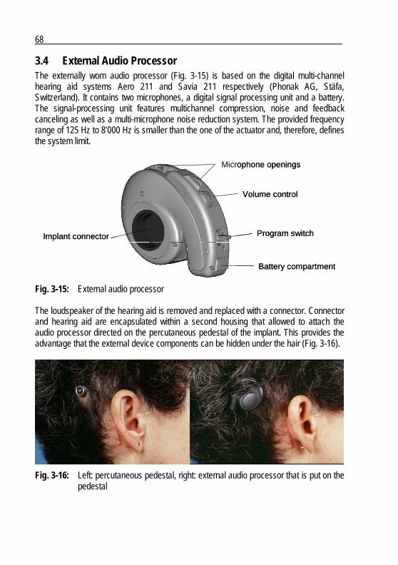
68
3.4 External Audio Processor The externally worn audio processor (Fig. 3-15) is based on the digital multi-channel hearing aid systems Aero 211 and Savia 211 respectively (Phonak AG, Stäfa, Switzerland). It contains two microphones, a digital signal processing unit and a battery. The signal-processing unit features multichannel compression, noise and feedback canceling as well as a multi-microphone noise reduction system. The provided frequency range of 125 Hz to 8’000 Hz is smaller than the one of the actuator and, therefore, defines the system limit.
Battery compartment
Implant connector
Microphone openings
Volume control
Program switch
Battery compartment
Implant connector
Microphone openings
Volume control
Program switch
Fig. 3-15: External audio processor The loudspeaker of the hearing aid is removed and replaced with a connector. Connector and hearing aid are encapsulated within a second housing that allowed to attach the audio processor directed on the percutaneous pedestal of the implant. This provides the advantage that the external device components can be hidden under the hair (Fig. 3-16).
Fig. 3-16: Left: percutaneous pedestal, right: external audio processor that is put on the pedestal
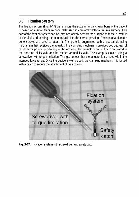
69
3.5 Fixation System The fixation system (Fig. 3-17) that anchors the actuator to the cranial bone of the patient is based on a small titanium bone plate used in craniomaxillofacial trauma surgery. This part of the fixation system can be intra-operatively bent by the surgeon to fit the curvature of the skull and to bring the actuator axis into the correct position. Conventional titanium bone screws are used to attach it. The plate is augmented with a special clamping mechanism that receives the actuator. The clamping mechanism provides two degrees of freedom for precise positioning of the actuator. The actuator can be freely translated in the direction of its axis and be rotated around its axis. The clamp is closed using a screwdriver with torque limitation. This guarantees that the actuator is clamped within the intended force range. Once the device is well placed, the clamping mechanism is locked with a catch to secure the attachment of the actuator.
Screwdriver withtorque limitation
Fixationsystem
Safetycatch
Screwdriver withtorque limitation
Fixationsystem
Safetycatch
Fig. 3-17: Fixation system with screwdriver and safety catch


71
4 Device Verification
4.1 Introduction As described in sub-section 1.6.2, the verification of the system characteristics consists in verifying all system requirements SR 1.1 to SR 12.2. This can be a simple measurement of a dimension such as the actuator diameter (SR 9.3), or a quite complex measurement of the actuator frequency response in order to verify SR 3.1, SR 3.2 and SR 3.3. This chapter will not cover all performed verification tests, but will concentrate on the functional tests that are directly related to the actuator performances, reliability and robustness. These are the key characteristics that will show if the actuator is qualified for implantation.
4.2 Actuator Performances The verification of the actuator performances includes several aspects that are all verified by assessing the actuator frequency response. The actuator frequency response shows if the frequency characteristic is similar to the one of the human middle ear (SR 3.1, SR 3.2 and SR 3.3), if the actuator efficiency is sufficient to reach an equivalent output of 125 dB SPL with 1 mW power input (SR 1.1 and SR 2.1) and if the frequency range is 100 Hz to 10’000 Hz (SR 2.2). Fig. 4-1 shows the measurement set-up that is used to assess the actuator transfer function. The measurement system is based on a Laser Doppler Vibrometer (PSV 200, Polytec GmbH, Waldbronn, Germany). With its internal signal generator it excites the actuator within the frequency range of 100 Hz to 10’000 Hz and measures in response the actuator driving voltage as well as the velocity of the artificial incus. The transfer function is finally calculated by dividing the velocity through the driving voltage.
Laserhead
Signalgenerator
Signalacquisition
Signalevaluation
Laserhead
Signalgenerator
Signalacquisition
Signalevaluation
Fig. 4-1: Actuator transfer function measurement set-up
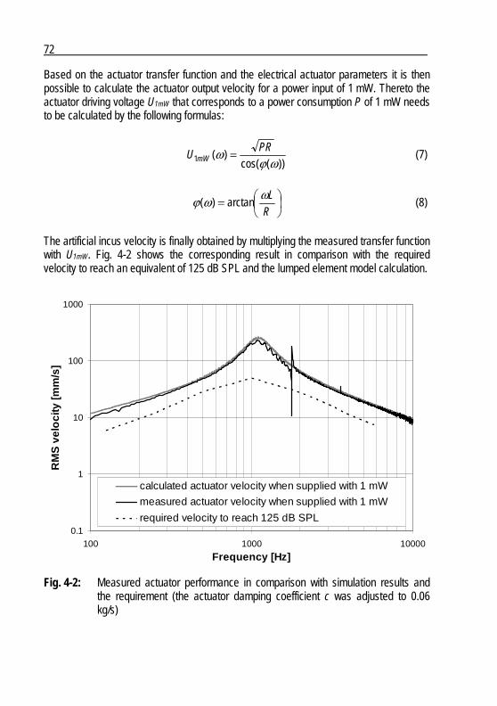
72
Based on the actuator transfer function and the electrical actuator parameters it is then possible to calculate the actuator output velocity for a power input of 1 mW. Thereto the actuator driving voltage U1mW that corresponds to a power consumption P of 1 mW needs to be calculated by the following formulas:
))(cos(
)(1 ωϕω PR
U mW = (7)
⎟⎠⎞
⎜⎝⎛=
RLωωϕ arctan)( (8)
The artificial incus velocity is finally obtained by multiplying the measured transfer function with U1mW. Fig. 4-2 shows the corresponding result in comparison with the required velocity to reach an equivalent of 125 dB SPL and the lumped element model calculation.
0.1
1
10
100
1000
100 1000 10000
Frequency [Hz]
RM
S v
elo
city
[mm
/s]
calculated actuator velocity when supplied with 1 mW
measured actuator velocity when supplied with 1 mW
required velocity to reach 125 dB SPL
Fig. 4-2: Measured actuator performance in comparison with simulation results and the requirement (the actuator damping coefficient c was adjusted to 0.06 kg/s)
73
Four conclusions are drawn from Fig. 4-2: First, the measurement shows a sharp parasitic resonance just below 2 kHz. This resonance is due to the fact that the mass of the artificial incus is not centered on the actuator shaft. This causes a lateral vibration mode of the coupling structure at the observed frequency. Once the actuator is implanted and coupled via a stapes prosthesis to the inner ear, this lateral mode is strongly attenuated (section 5.4). Second, after fitting of the actuator-damping coefficient, the measured and simulated curves are almost congruent. This proves that the lumped element model describes the actuator accurately and is, therefore, a suitable design tool. Third, because the provided velocity of the actuator driven with 1 mW input power exceeds the required 125 dB curve in the whole frequency range from 100 Hz to 10’000 Hz by an average of 5 dB, the actuator is even more efficient than required. This performance reserve allows for the acceptance of actuators with less ideal frequency responses and resonance frequencies of up to 2 kHz to increase the device-manufacturing yield. Fourth, the actuator characteristic follows the middle ear characteristic very precisely. This means that this major design goal is achieved. Only at the resonance is the actuator less damped than a normal human middle ear and shows a deviation of the curve progression. This under-damping is important in accounting for the additional damping due to the coupling and particularly tissue growth as shown in section 5.4. Finally it can be concluded, that the actuator meets all the specified performance requirements.
4.3 Actuator Reliability The verification of the reliability has to prove that the actuator will operate for the specified lifetime of two years (SR 6.1) without losing its hermeticity (SR 7.2). This is essential for the therapeutic performance of the device. If the actuator would become leaky, the patient would be at risk and the device would have to be explanted. The big challenge in this case is to accelerate the corresponding tests in order to verify the device lifetime within a reasonable period of time. In most of the cases the necessary acceleration is accomplished by increasing the temperature and by exceeding the specified power limit of the device. Unfortunately, this procedure requires that the impact of these factors is exactly known. Since the present device is the first of its kind, this required knowledge is not yet available. Therefore another approach has to be found.
74
The selected approach is based on two tests. First of all, the actuator is analyzed in order to identify its weakest element. Regarding the actuator design (Fig. 3-12) it is apparent that it is the diaphragm. This titanium foil with a thickness of 25 µ m is constantly under mechanical stress and has at the same time to maintain the hermeticity of the actuator. Therefore a diaphragm fatigue test is carried out in order to assess its fatigue limit (sub-section 4.3.1). The second test is a life cycle test of the complete actuator (sub-section 4.3.2). The reason for this test is to monitor the long term behavior of a complete actuator.
4.3.1 Diaphragm Fatigue Titanium shows a particular fatigue behavior that differs from other nonferrous metals. Instead of a stress vs. load cycles characteristic that slopes gradually downwards with increasing number of cycles, titanium shows a limit stress value (fatigue limit). If the stresses stay below this limit, the mechanical structure can endure an infinite number of cycles without failure (Fig. 4-3). Literature shows that this limit is reached between 105 and 107 cycles. To be on the save side, the tests described below will be carried out with 107 cycles.
Fig. 4-3: Typical stress vs. cycles characteristic of titanium [50] A strain-controlled fatigue test is carried out. The corresponding staircase test procedure is described in [51]. The test set-up is shown in Fig. 4-4. It is based on load generator developed for this specific purpose.
75
Clampeddiaphragm fatigue
test housing
Laserhead
Signalgenerator
Signalacquisition
Signalevaluation
Loadgenerator
Clampeddiaphragm fatigue
test housing
Laserhead
Signalgenerator
Signalacquisition
Signalevaluation
Loadgenerator
Fig. 4-4: Diaphragm fatigue test set-up: the load generator deflects the diaphragm of the clamped test housing; the deflection amplitude is monitored by the laser vibrometer
The assessed fatigue limit of the diaphragm is 2.5 times above the maximal specified actuator velocity considering a failure probability of 10-4, a confidence of the assessed mean value of 99% and a confidence of the assessed standard deviation of 90%. This shows that the maximal strain of the diaphragm that occurs during intended operation of the device stays below the fatigue limit. The diaphragm should therefore stay intact during the specified lifetime of two years with a probability of more than 99.99%.
4.3.2 Life Cycle Test As mentioned above, it does not make sense to accelerate the aging of the actuator. Therefore it is decided to run test actuators at worst but still representative conditions (Fig. 4-5):
Input power: 1 mW Temperature: 37°C Humidity: 100% Load: artificial cochlea Device activation: continuous
The test is started three months prior to first human implantation. In this way the aging of the test actuators is at least three months in advance compared to the implanted devices in order to provide enough reaction time in case of a test device failure. The test actuators are inspected in regular intervals. These inspections include the verification of the main actuator characteristics like frequency response and encapsulation integrity.

76
37°C100% humidity
Art
ifici
al c
ochl
ea
Signalgenerator 37°C
100% humidity
Art
ifici
al c
ochl
ea
Signalgenerator
Fig. 4-5: Life cycle test set-up: the actuators are placed in a climatic chamber that simulates implanted conditions (37°C and 100% humidity); the actuators are driven with the specified maximal power input of 1 mW and coupled to an artificial cochlea
Up to date the test is continuously running for six years without causing any actuator failure. This confirms the result of the diaphragm fatigue test and proves that the actuator lifetime exceeds the required two years.
4.4 Actuator Robustness Two main aspects regarding the device robustness are:
The device has to withstand all the necessary manipulations related to the implantation procedure
The device has to withstand environmental conditions during transportation, storage and intended use
4.4.1 External Forces The attachment of the stapes prosthesis to the artificial incus is the most critical implantation step from the actuator perspective. This manipulation exerts forces on the mobile part of the actuator and therefore deflects the diaphragm. This involves the risk of damaging the diaphragm and causing a leak or a change of the actuator frequency response. Therefore the actuator has to withstand forces that are exerted during this implantation step (SR 10.1 and SR 10.2).

77
The test procedure consists of the following main steps: Measurement of the actuator frequency response prior to application of the load
forces Application of multiple force cycles on the artificial incus in axial and radial
direction Measurement of the actuator frequency response after the application of the
load forces The comparison of the two assessed frequency responses does not show a significant change of the actuator characteristic. This proves that the actuator is not affected by the necessary manipulations during implantation.
4.4.2 Environmental Influences An active implantable medical device has to be 100% functional at the moment of implantation. Implanting a defective device would have fatal consequences and has to be prevented. Therefore all active implantable medical devices have to be sufficiently robust to withstand any environmental influence during transportation, storage and intended use. The corresponding requirements are specified in EN45502 and include pressure (SR 11.1 and SR 11.2), mechanical shock (SR 5.1) and temperature (SR 11.3 and SR 11.4) resistance. The actuator is very sensitive to pressure and temperature because of its hermetic housing design. The diaphragm becomes deflected in response to pressure and temperature changes and could therefore be damaged. Mechanical shocks are less critical because the mobile actuator mass of 35 mg is sufficiently small that shocks cannot cause significant forces. All three environmental influences are tested according to the same basic procedure, which is already described in the previous sub-section:
Measurement of the actuator frequency response prior exposure to the corresponding environmental influence
Exposure of the actuator to multiple environmental load cycles Measurement of the actuator frequency response after exposure
None of the three tested environmental influences caused a significant change of the actuator frequency response. This proves that the actuator does withstand the stresses that can occur during transportation, storage and intended use of the device.
78
4.5 Conclusion The verification of the actuator characteristics against the specified system requirements was successful. This means that the actuator meets all system requirements and is therefore qualified for implantation. It has to be kept in mind that this “only” signifies that the actuator is as good as its requirements. It does not automatically guarantee that the actuator provides a sufficient therapeutic performance. Nevertheless the design aimed to cover all important aspects with help of the presented conceptual design methodology. This should ensure that the technical performance is representative for the final therapeutic performance. The corresponding validation step is described in the next chapter.
79
5 Therapy Validation
5.1 Introduction Is the described and applied methodology able to provide a conceptual design that leads to a “useful” device? This question shall be answered in this chapter that summarizes the clinical study which started about twelve months after the project initiation. If its results confirm a satisfying therapeutic performance of the device, this will prove that conceptual design is well adapted to the present application and that all relevant environmental influences were properly considered.
5.2 Summary of Clinical Study Protocol A well specified clinical protocol is essential for the validation of a new therapy. The study goals, the corresponding test procedures and the included patient population have to be carefully chosen in order to get meaningful results. Ethical aspects have to be considered as well. The risk for the patient has to be minimized and has to be in a justifiable proportion to the possible benefit. The study goals were defined as follows: Primary objective: To demonstrate that the DACS system can efficiently manage
severe to profound mixed hearing loss Secondary objectives: 1) To demonstrate safety and feasibility of the surgical procedure
for the DACS actuator combined with a stapes prosthesis 2) To demonstrate safety of using the DACS actuator combined
with a stapes prosthesis The primary study objective is verified by assessing the post-operative aided free field hearing thresholds of the patients. The thresholds have to be better than 40 dB HL at 500, 1000, 2000 and 4000 Hz. The secondary study objectives were verified by reporting and analyzing
all surgical complication related to the implantation of the device the aided hearing performance during the length of the study including
improvement or degradation of the device performance all post-operative complications related to the device
The patients included in the study had to fulfil the following criteria:

80
Bilateral or unilateral mixed hearing loss with a conductive component due to otosclerosis and a sensorineural component (since a patient with otosclerosis would be indicated for stapedectomy in any case, the implantation of the DACS device did not much increase the patient risk)
Measurable bone conduction thresholds at 500, 1000, 2000, 3000 and 4000 Hz with standard clinical equipment (this ensured that the sensorineural loss was not to severe for post-operative DACS usage)
Sensorineural loss less than that indicated for a cochlear implant Bone conduction thresholds greater than 40 dB for at last three out of the five
frequencies mentioned above and bone conduction thresholds equal or greater than 30 dB on all frequencies (this ensured that even though normal stapedectomy will be successful, the patient still needed a hearing aid post surgery)
Air-bone-gap equal or greater than 20 dB for at least three out of the five frequencies mentioned above (this ensured that the patients were candidates for stapedectomy)
Audiometric follow-up data available from at least one year before enrolment (this was important to have a reliable assessment of the patient’s hearing loss)
Progression of the sensorineural component of the hearing loss less than 10 dB measured over the last year (this ensured that the DACS device was able to restore the hearing loss until the end of the clinical study after two years)
Experience with conventional high power hearing aids for a minimum of six weeks prior to enrolment (since the operation of the DACS device is identical to that of a conventional hearing aid, this ensured that the patients were able to correctly operate such a device)
Willingness to participate in the study and sign the informed consent (the patients had to be conscious of the risks of the clinical study in order to kept their expectations at a realistic level)
Excluded from the study were patients that fulfilled the following criteria:
Inability to comply with the study follow-up Failure to obtain written informed consent Medical contra-indication that would prevent surgery Unrealistic expectations regarding the outcome of the intervention Anyone under the age of 18 Inability to maintain personal hygiene in order to keep the percutaneous
pedestal clean An additional goal of this clinical study was to compare the therapeutic performance of the DACS device with the current reference treatment consisting of the combination of stapedectomy and a conventional hearing aid (sub-section 1.5.1). This was possible due to a special surgical technique described in detail in section 5.4. In order to minimize the consequences for the patient in case of a DACS device failure, a conventional
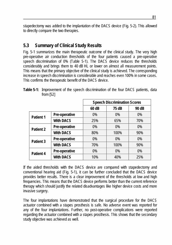
81
stapedectomy was added to the implantation of the DACS device (Fig. 5-2). This allowed to directly compare the two therapies.
5.3 Summary of Clinical Study Results Fig. 5-1 summarizes the main therapeutic outcome of the clinical study. The very high pre-operative air conduction thresholds of the four patients caused a pre-operative speech discrimination of 0% (Table 5-1). The DACS device reduces the thresholds considerably and brings them to 40 dB HL or lower on almost all measurement points. This means that the primary objective of the clinical study is achieved. The corresponding increase in speech discrimination is considerable and reaches even 100% in some cases. This confirms the therapeutic benefit of the DACS device. Table 5-1: Improvement of the speech discrimination of the four DACS patients, data
from [52]
Speech Discrimination Scores
60 dB 75 dB 90 dB
Pre-operative 0% 0% 0% Patient 1
With DACS 25% 65% 70%
Pre-operative 0% 0% 0% Patient 2
With DACS 80% 100% 90%
Pre-operative 0% 0% 0% Patient 3
With DACS 70% 100% 90%
Pre-operative 0% 0% 0% Patient 4
With DACS 10% 40% 25% If the aided thresholds with the DACS device are compared with stapedectomy and conventional hearing aid (Fig. 5-1), it can be further concluded that the DACS device provides better results. There is a clear improvement of the thresholds at low and high frequencies. This means that the DACS device performs better than the current reference therapy which should justify the related disadvantages like higher device costs and more invasive surgery. The four implantations have demonstrated that the surgical procedure for the DACS actuator combined with a stapes prosthesis is safe. No adverse event was reported for any of the four implantations. Further, no post-operative complications were reported regarding the actuator combined with a stapes prosthesis. This shows that the secondary study objective was achieved as well.
82
Since all study objectives were successfully achieved, it can be concluded that device concept is appropriate. This implies that the applied conceptual design methodology has provided useful output.
Patient 1Patient 1
Patient 2Patient 2

83
Patient 3Patient 3
Patient 4Patient 4
Fig. 5-1: Hearing thresholds of the four DACS patients indicating their pre-operative air conduction thresholds (circles and crosses) and the post-operative aided thresholds (squares and triangles); DACS: continuous lines, stapedectomy and conventional hearing aid: dashed lines, data from [52]
84
5.4 Surgical Procedure Fig. 5-2 shows the situation after implantation of the investigational DACS device. The actuator is placed in a temporal bone cavity that was drilled by surgeon (Fig. 5-3b). It is hold in place by the fixation system which is screwed to the cranial bone (Fig. 5-3c). The percutaneous pedestal is screwed a little bit more behind. As shown in the magnified view through the auditoy canal, two stapes prostheses were implanted. One is attached to the artificial incus of the actuator (Fig. 5-3f) and a second one is attached to the real incus like during a conventional stapedectomy (Fig. 5-3d).
Conventionalstapes
prosthesis
Percutaneous pedestal
Lead Fixationsystem
DACS stapesprosthesis
Actuator
Ovalwindow
Conventionalstapes
prosthesis
Percutaneous pedestal
Lead Fixationsystem
DACS stapesprosthesis
Actuator
Ovalwindow
Fig. 5-2: Schematic drawing of the implanted investigational DACS device, modified after [52]
In the case of the DACS device, the surgical procedure is more than manipulation of human tissue and the placement of device components. The procedure (Fig. 5-3) has direct impact on the performance of the device. On the one hand the actuator has to be carefully handled in order to prevent damage. On the other hand the attachment and placement of the stapes prosthesis directly influence the device performance. The design of the actuator has to account for these influences and to support the manipulation by the surgeon as much as possible. These aspects were covered by determining the corresponding system environments as prescribed by the conceptual design methodology. After placement of all system components, an intra-operative device test (section 5.5) was carried out to check the integrity of the system and to verify that the stapes prosthesis can freely move within the oval window.
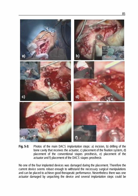
85
Fig. 5-3: Photos of the main DACS implantation steps: a) incision, b) drilling of the bone cavity that receives the actuator, c) placement of the fixation system, d) placement of the conventional stapes prosthesis, e) placement of the actuator and f) placement of the DACS stapes prosthesis
No one of the four implanted devices was damaged during the placement. Therefore the current device seems robust enough to withstand the necessary surgical manipulations and can be placed to achieve good therapeutic performance. Nevertheless there was one actuator damaged by unpacking the device and several implantation steps could be
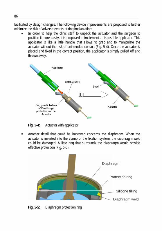
86
facilitated by design changes. The following device improvements are proposed to further minimize the risk of adverse events during implantation:
In order to help the clinic staff to unpack the actuator and the surgeon to position it more easily, it is proposed to implement a disposable applicator. This applicator is like a little handle that allows to grab and to manipulate the actuator without the risk of unintended contact (Fig. 5-4). Once the actuator is placed and fixed in the correct position, the applicator is simply pulled off and thrown away.
Fig. 5-4: Actuator with applicator
Another detail that could be improved concerns the diaphragm. When the actuator is inserted into the clamp of the fixation system, the diaphragm weld could be damaged. A little ring that surrounds the diaphragm would provide effective protection (Fig. 5-5).
Diaphragm
Protection ring
Silicone filling
Diaphragm weld
Diaphragm
Protection ring
Silicone filling
Diaphragm weld
Fig. 5-5: Diaphragm protection ring
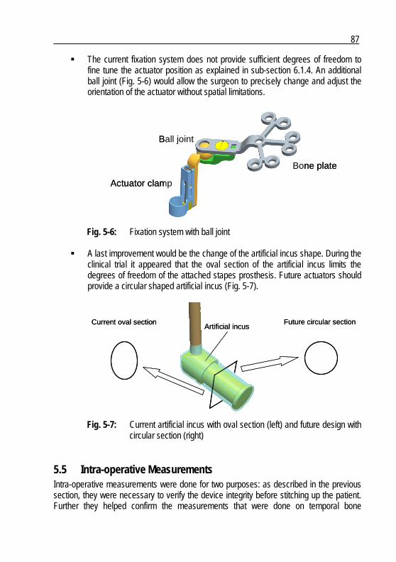
87
The current fixation system does not provide sufficient degrees of freedom to fine tune the actuator position as explained in sub-section 6.1.4. An additional ball joint (Fig. 5-6) would allow the surgeon to precisely change and adjust the orientation of the actuator without spatial limitations.
Bone plate
Ball joint
Actuator clamp
Bone plate
Ball joint
Actuator clamp
Fig. 5-6: Fixation system with ball joint
A last improvement would be the change of the artificial incus shape. During the clinical trial it appeared that the oval section of the artificial incus limits the degrees of freedom of the attached stapes prosthesis. Future actuators should provide a circular shaped artificial incus (Fig. 5-7).
Artificial incusCurrent oval section Future circular section
Artificial incusCurrent oval section Future circular section
Fig. 5-7: Current artificial incus with oval section (left) and future design with circular section (right)
5.5 Intra-operative Measurements Intra-operative measurements were done for two purposes: as described in the previous section, they were necessary to verify the device integrity before stitching up the patient. Further they helped confirm the measurements that were done on temporal bone
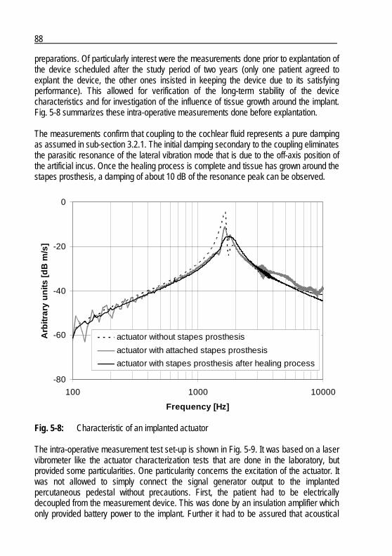
88
preparations. Of particularly interest were the measurements done prior to explantation of the device scheduled after the study period of two years (only one patient agreed to explant the device, the other ones insisted in keeping the device due to its satisfying performance). This allowed for verification of the long-term stability of the device characteristics and for investigation of the influence of tissue growth around the implant. Fig. 5-8 summarizes these intra-operative measurements done before explantation. The measurements confirm that coupling to the cochlear fluid represents a pure damping as assumed in sub-section 3.2.1. The initial damping secondary to the coupling eliminates the parasitic resonance of the lateral vibration mode that is due to the off-axis position of the artificial incus. Once the healing process is complete and tissue has grown around the stapes prosthesis, a damping of about 10 dB of the resonance peak can be observed.
-80
-60
-40
-20
0
100 1000 10000
Frequency [Hz]
Arb
itrar
y u
nits
[dB
m/s
]
actuator without stapes prosthesis
actuator with attached stapes prosthesis
actuator with stapes prosthesis after healing process
Fig. 5-8: Characteristic of an implanted actuator The intra-operative measurement test set-up is shown in Fig. 5-9. It was based on a laser vibrometer like the actuator characterization tests that are done in the laboratory, but provided some particularities. One particularity concerns the excitation of the actuator. It was not allowed to simply connect the signal generator output to the implanted percutaneous pedestal without precautions. First, the patient had to be electrically decoupled from the measurement device. This was done by an insulation amplifier which only provided battery power to the implant. Further it had to be assured that acoustical
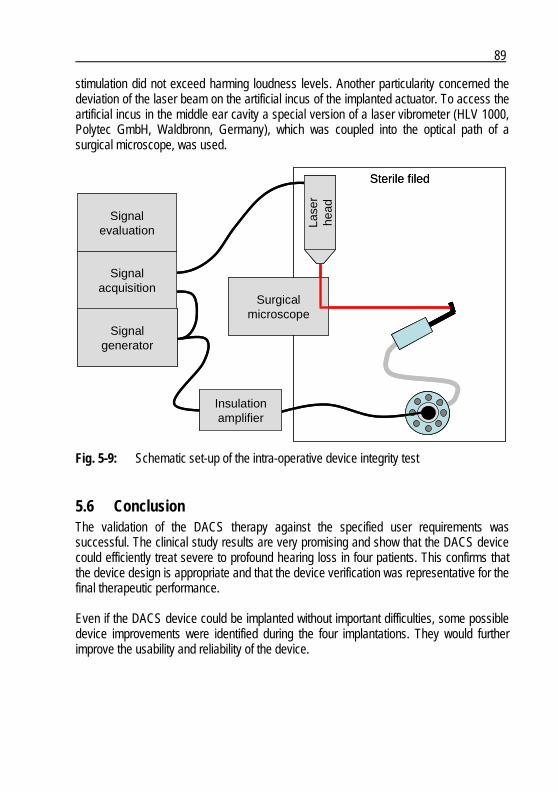
89
stimulation did not exceed harming loudness levels. Another particularity concerned the deviation of the laser beam on the artificial incus of the implanted actuator. To access the artificial incus in the middle ear cavity a special version of a laser vibrometer (HLV 1000, Polytec GmbH, Waldbronn, Germany), which was coupled into the optical path of a surgical microscope, was used.
Signalgenerator
Signalacquisition
Signalevaluation
Insulationamplifier
Lase
rhe
ad
Sterile filed
Surgicalmicroscope
Signalgenerator
Signalacquisition
Signalevaluation
Insulationamplifier
Lase
rhe
adLa
ser
head
Sterile filed
Surgicalmicroscope
Fig. 5-9: Schematic set-up of the intra-operative device integrity test
5.6 Conclusion The validation of the DACS therapy against the specified user requirements was successful. The clinical study results are very promising and show that the DACS device could efficiently treat severe to profound hearing loss in four patients. This confirms that the device design is appropriate and that the device verification was representative for the final therapeutic performance. Even if the DACS device could be implanted without important difficulties, some possible device improvements were identified during the four implantations. They would further improve the usability and reliability of the device.


91
6 Conclusions
6.1 Overview
6.1.1 Design Methodology This thesis proposes a conceptual design methodology for acoustic hearing implants. The methodology was applied to develop an investigational hearing implant that was successfully tested and implanted in four patients. Based on this project outcome and the experience gathered during the development, it is possible to draw the following conclusions regarding the entire design process and the conceptual design methodology:
The employed design processes allowed for a fast and efficient development of the investigational DACS device.
The good clinical study results show that the employed design processes were effective.
The conceptual design methodology allowed to well analyze the device application and to identify the interactions with the involved environments. This led to a comprehensive set of user and system requirements. The fact that no device failure occurred so far and that the therapeutic performance is satisfying indicates that all relevant aspects were considered.
The conceptual design methodology helped to well structure the complex design task and to break the system down into manageable portions without neglecting important design aspects.
The conceptual design methodology helped to find an integrated solution by considering the interactions between the “generation of vibrations” and the “hermetic housing” functions. This was probably the key element that allowed to develop a device that seems to outperform comparable devices.
The conceptual design methodology led to an innovative actuator concept that differs from all hearing implant actuator designs published so far.
Since the conceptual design methodology provided a solid system concept, the detailed design can be based on simple and efficient procedures.
The models used for the detailed design of the actuator represented a good compromise between accuracy and simplicity. This was confirmed by the simulations results that corresponded well to measured characteristics of the actuator.
6.1.2 Therapy The results of the clinical study have shown that the DACS device could effectively treat severe to profound mixed hearing loss in all four cases. When comparing the DACS
92
therapy with a combination of conventional hearing aid and stapedectomy, which serves as reference, it can be observed that
The DACS device provides better hearing thresholds at low and high frequencies
At middle frequencies the DACS device provides at least as good hearing thresholds
A direct comparison with other implantable hearing devices indicated for mixed hearing loss is impossible, since the published data for the Soundbridge (placed on the round window) and the Carina (coupled to the round window) are based on patient populations that have considerable lower hearing loss than the patients of the DACS clinical trial. Nevertheless the study results suggest that the DACS device provides higher gain in terms of speech understanding and improved hearing threshold than reported for the other systems.
6.1.3 Implantation The four implantations that were accomplished by experienced ear surgeons have shown that simple and safe handling procedures are very important to prevent damaging the fragile actuator. This concerns packaging design and handling tools. Concretely it was observed that critical forces could impact on the artificial incus when the implant is improperly taken out of its packaging. The manipulation of the actuator with standard surgical forceps caused difficulties as well. The grip between the instrument and the actuator was not always sufficient, and the limited number of gripping positions caused difficulties in some cases during the placement of the actuator. These are good examples that highlight again the importance of a holistic design approach. Good usability is of central interest for such a delicate device that requires high handlings skills. The success of the therapy depends as much on the work of the surgeon as on the device characteristics. Therefore the product design has to support the user as much as possible and to prevent unintended manipulation whenever possible – especially in the case of a medical device.
6.1.4 Device Technical verification and clinical validation have shown that the investigational DACS device meets the performance requirements and provides sufficiently high stimulation levels to treat severe to profound mixed hearing loss. Further, records of over five years
93
of operation in patients and over six years of continuous life cycle testing in the lab show that the device is reliable and operates permanently within its specifications. This proves that the device is sufficiently robust and reliable to serve as long term implantable device as required for a hearing implant. The major device drawback concerns the percutaneous connection between the external audio processor and the implanted actuator. On the one hand, it required some training of the patients until they were able to correctly connect the processor plug to the implanted pedestal. On the other hand, the percutaneous pedestal caused infections of the surrounding tissue. Another issue concerned the placement of the actuator. It was difficult to position the artificial incus sufficiently precisely over the oval window. The provided degrees of freedom for the fine tuning of the actuator position were not sufficient, because the actuator axis could not be changed anymore once the fixation system was screwed to the skull.
6.2 Originality
6.2.1 Conceptual Design Methodology The design of an acoustic hearing implant is a very challenging task. This is confirmed by the analysis of existing devices (sub-section 2.2.2) that all show one or another imperfection. The observed imperfections can be attributed to conceptual design decisions in most of the cases. Therefore it is essential to better structure and guide the conceptual design process by formalizing a dedicated methodology. Since no corresponding basis could be found in literature, the presented conceptual design methodology is elaborated from scratch. It consists of a step-by-step procedure and a diagram tool that visualizes the system, its environments and the corresponding interactions. The described methodology merges the three essential definition steps of a medical device development that are normally executed in sequence to one procedure. This approach minimizes the risk of isolating the technical development from the initial user requirements of an acoustic hearing implant. The presented approach focuses on the conceptual design phase in order to maximize the overall device performance. Especially in the field of active implantable medical devices, where technology has to be joined to living tissue, the global optimum has to be searched on concept level. Pure technical benchmarks that are maximized during the detailed design phase are less relevant in this case.

94
6.2.2 Resulting Innovative Actuator Design A side effect of the applied conceptual design methodology was that the solutions for the individual functions are “enforced” by their environments. The fact that the acoustical hearing implant was developed for severe to profound mixed hearing loss influenced considerably the actuator design. Further, the consideration of the interactions between the different actuator functions as well as between the actuator and its environments led to an integrated design solution instead of a compromise. The resulting actuator is the first one that was consequently designed for the treatment of mixed hearing loss and differs form other existing hearing implant actuators. Its most remarkable characteristic is that the encapsulation was considered as a functional part and included into the actuation concept. This allowed to minimize losses and to optimize the actuator frequency response.
6.3 Outlook
6.3.1 Methodology Refinements The proposed conceptual design methodology provided satisfying outputs in the present case. The procedure was easily applicable and has well supported the conceptual design process. Hence there is currently no concrete suggestion to refine the methodology. It would be interesting to apply the methodology for the development of other acoustic hearing implants to further verify its validity. Of particular interest would be to investigate how the actuator design changes in function of alternative requirements. The methodology might also be of interest for the development of artificial organs in general. Trials would have to show if the design principles that are adapted to the ear are also valid for the eye or the heart for example.
6.3.2 Implementation of Transcutaneous Link The central weakness of the DACS investigational device is the percutaneous signal transmission. Comparable semi-implantable hearing devices are equipped with a wire-less transcutaneous power and signal transmission which provides much higher patient comfort. Fig. 6-1 shows the second generation DACS device with implemented transcutaneous transmission.
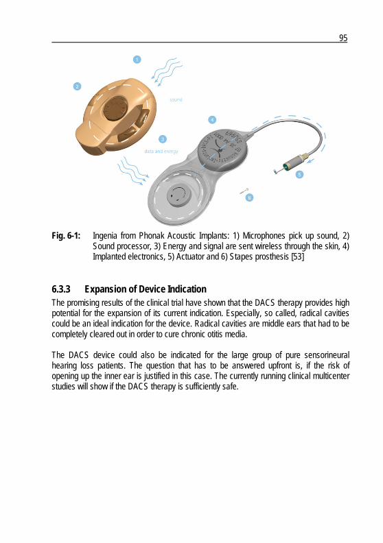
95
Fig. 6-1: Ingenia from Phonak Acoustic Implants: 1) Microphones pick up sound, 2)
Sound processor, 3) Energy and signal are sent wireless through the skin, 4) Implanted electronics, 5) Actuator and 6) Stapes prosthesis [53]
6.3.3 Expansion of Device Indication The promising results of the clinical trial have shown that the DACS therapy provides high potential for the expansion of its current indication. Especially, so called, radical cavities could be an ideal indication for the device. Radical cavities are middle ears that had to be completely cleared out in order to cure chronic otitis media. The DACS device could also be indicated for the large group of pure sensorineural hearing loss patients. The question that has to be answered upfront is, if the risk of opening up the inner ear is justified in this case. The currently running clinical multicenter studies will show if the DACS therapy is sufficiently safe.

97
Glossary of Symbols
AL armature length AR armature radius ASL armature shaft length ASR armature shaft radius ASTM American Society for Testing and Materials BAHA bone anchored hearing aid β electro-mechanic conversion constant BTE behind the ear (hearing aid) c actuator damping coefficient CCIR coil core inner radius CCL coil core length CI cochlear implant CIC completely in the canal (hearing aid) CIR coil inner radius cL mechanical impedance of the cochlea CL coil length COR coil outer radius CSIR coil shell inner radius CSL coil shell length DACS direct acoustic cochlear stimulation DC direct current EN European Norm ETi Young's modulus of titanium ETO ethylene oxide F complex magnetic force FMT floating mass transducer fres resonance frequency g gravitational acceleration GL gap length GPL gap part length HA hearing aid HL hearing loss i complex coil current id inner diameter ISL iron shim length ISO International Organization for Standardization ITC in the canal (hearing aid) ITIR iron tube inner radius ITL iron tube length
98
j imaginary unit k actuator spring constant kD spring constant attributed to the magnets kM spring constant attributed to the diaphragm L actuator inductance LDV Laser Doppler Vibrometer m mass M.E.T. middle ear transducer MEI middle ear implant MES middle ear surgery MIL-STD Military Standard MIR magnet inner radius ML magnet length MOR magnet outer radius νTi Poisson coefficient of titanium od outer diameter ω circular frequency OR outer radius P real power φ phase angle R electrical resistance SPL sound pressure level SR system requirement th thickness TICA totally implantable cochlear amplifier TORP total ossicular chain replacement prosthesis u complex coupling voltage U1mW voltage corresponding to 1 mW power consumption ue complex actuator excitation voltage UR user requirement v complex armature velocity Ym complex mechanical actuator admittance Z complex electrical actuator impedance
99
References
[1] M. Bear, B. Connors, M. Paradiso, Neuroscience – Exploring the Brain, Williams & Wilkins, 1996
[2] C. Stieger, Implantable Hearing Systems: Development and Evaluation of Two Concepts, Dissertation, University of Neuhâtel, Switzerland, 2006
[3] M. Chasin, Current Trends in Implantable Hearing Aids, Trends in Amplification, vol. 2, no. 3, pp. 84-107, 1997
[4] D. Haynes, J. Young, G. Wanna, M. Glasscock, Middle Ear Implantable Hearing Devices: An Overview, Trends in Amplification, vol. 13, no. 3, pp. 206-214, 2009
[5] https://mentor.ieee.org/802.15/dcn/08/15-08-0365-01-0006-hearing-aids-cutting-edge-technology-in-an-ultra-constrained-environment.ppt#450,6,Hearing Aid Market at a Glance, 2008
[6] www.phonak.ch, 2010 [7] R. Häusler, Fortschritte in der Stapeschirurgie, Laryngo-Rhino-Otol vol. 79, no. 2, pp
95-139, 2000 [8] J. Shea, Forty Years of Stapes Surgery, Am J Otol., vol. 19, pp. 52-55, 1998 [9] www.kurzmed.de, 2010 [10] www.swissear.ch, 2010 [11] http://nucleus5.cochlear.com/de, 2010 [12] K.-B. Hüttenbrink, Middle Ear Mechanics and their Interface with Respect to
Implantable Electronic Otologic Devices, Otol. Clinics of North America, vol. 34, no. 2, pp. 315-335, 2001
[13] M. Chasin, J. Spindel, Middle Ear Implants: A New technology, The Hearing Journal, vol. 54, no. 8, pp. 33-48, 2001
[14] R, Goode, Current Status and Future of Implantable Electromagnetic Hearing Aids, Otol. Clinics of North America, vol. 28, no. 1, pp. 141146, 1995
[15] J. Fredrickson, J. Coticchia, S. Khosla, Current Status in the Development of Implantable Middle Ear Hearing Aids, Advances in Otolaryngology, vol. 10, pp. 189-204, 1996
[16] H. Zenner, H. Leysieffer, Aktive elektronische Hörimplantate für Mittel- und Innenohrschwerhörige – eine neue Ära der Ohrchirurgie, Teil I: Grundprinzipien und Nomenklaturvorschlag, HNO, vol. 45, pp. 749-757, 1997
[17] H. Zenner, H. Leysieffer, Aktive elektronische Hörimplantate für Mittel- und Innenohrschwerhörige – eine neue Ära der Ohrchirurgie, Teil II: Gegenwärtiger Entwicklungsstand, HNO, vol. 45, pp. 758-768, 1997
[18] H. Zenner, H. Leysieffer, Aktive elektronische Hörimplantate für Mittel- und Innenohrschwerhörige – eine neue Ära der Ohrchirurgie, Teil III: Perspektiven für Innenohrschwerhörige, HNO, vol. 45, pp. 769-774, 1997
[19] www.medel.com, 2010
100
[20] V. Colleti, S. Soli, M. Carner, L. Colleti, Treatment of Mixed Hearing Losses Via Implantation of a Vibratory Transducer on the Round Window, int. J. Audiol., vol. 45, pp. 904-916, 2006
[21] S. Tringali, N. Pergola, P. Berger, C. Debreuil, Fully Implantable Hearing Device with Transducer on the Round Window as a Treatment of Mixed Hearing Loss, Auris Nasus Larynx, vol. 36, pp. 353-358, 2009
[22] E. Lehnhardt, R. Laszig, Praxis der Audiometrie, Thieme, 2001 [23] G. Bergmann, J. Daub, Systemisches Innovations- und Kompetenzmanagement,
Gabler, pp. 202-204, 2006 [24] J. Shah, Experimental Investigation of Collaborative Techniques for Progressive
Idea Generation, proceedings of the Design Engineering Technical Conference (ASME DETC98), Atlanta, GA, Sep. 13-16, 1998
[25] VDI 2221, Methodik zum Entwickeln und Konstruieren technischer System und Produkte
[26] W. Ko, W. Zhu, A. Maniglia, Engineering Principles of Mechanical Stimulation of the Middle Ear, Otolaryngologic Clinics of North America, vol. 28, pp. 29-41, 1995
[27] H. Leysieffer, Prinzipielle Anforderungen an einen elektromechanischen Wandler für implantierbare Hörgeräte bei Innenohrschwerhörigkeit, Teil I: Technische und audiologische Aspekte, HNO, vol. 45, pp. 775-786, 1997
[28] H. Leysieffer, Prinzipielle Anforderungen an einen elektromechanischen Wandler für implantierbare Hörgeräte bei Innenohrschwerhörigkeit, Teil II: Klinische Aspekte, HNO, vol. 45, pp. 787-791, 1997
[29] H. Leysieffer, J. Baumann, G. Müller, H. Zenner, Ein implantierbarer piezoelektrischer Hörgerätewandler für Innenohrschwerhörige, Teil I: Entwicklung eines Prototypen, HNO, vol. 45, pp. 792-800, 1997
[30] H. Leysieffer, J. Baumann, G. Müller, H. Zenner, Ein implantierbarer piezoelektrischer Hörgerätewandler für Innenohrschwerhörige, Teil II: Klinisches Implantat, HNO, vol. 45, pp. 801-815, 1997
[31] P. Counter, Implantable Hearing Aids, Proc. IMechE Part H: J. Engineering in Medicine, vol. 222, no. 6, 2008
[32] J. Spindel, Middle Ear Implants: An Overview, 2007 [33] J. Fredrickson, Middle Ear Implants: The Otologics MET Ossicular Stimulator, The
Hearing Journal, vol. 54, no. 8, pp. 46-47, 2001 [34] J. Kasic, J. Fredrickson, The Otologics MET Ossicular Stimulator, Otolaryngol Clin
North Am, vol. 34, no. 2, pp. 501-514, 2001 [35] H. Jenkins, J. Atkins, D. Horlbeck, M. Hofferr, B. Balough, J. Arigo, U.S. Phase I
Preliminary Results of Use of the Otologics MET Fully-implantable Ossicular Stimulator, Otolaryngology – Head and Neck Surgery, vol. 137, pp. 206-212, 2007
[36] J. Bedoya, J. Easter, J. Kasic, D. Miller, Implantable Hearing Aid with Improved Sealing, Patent WO 03/030584 A2, 2003
[37] www.hno.uniklinik-bonn.de, 2010 [38] www.middleearimplants.com, 2010 [39] T. Lenarz, B. Weber, P. Issing, D. Gnadeberg, K. Ambjornsen, K. Mack, M. Winter,
Vibrant Sound Bridge System. A new kind hearing prosthesis for patients with
101
sensorineural hearing loss. 2. Audiological results, Laryngorhinootologie, vol. 80, no. 7, pp. 370-380, 2001
[40] A. Uziel, M. Mondain, P. Hagen, F. Dejean, G. Doucet, Rehabilitation for high-frequency sensorineural hearing impairment in adults with the symphonix vibrant soundbridge: a comparative study, Otol Neurotol., vol. 24, no. 5, pp. 775-783, 2003
[41] I. Mosnier et al., Benefit of the Vibrant Soundbridge device in patients implanted for 5 to 8 years, Ear Hear, vol. 29, no. 2, pp. 281-284, 2008
[42] Hearing Technology, Vibrant MED-EL, General Presentation, 2004 [43] D. Chen, D. Backous, M. Arriaga, R. Garvin, D. Kobylek, T. Littman, S. Walgren, D.
Lura, Phase 1 clinical trial results of the envoy system: A totally implantable middle ear device for sensorineural hearing loss, Otolaryngology – Head and Neck Surgery, vol. 131, no. 6, pp. 904-916, 2004
[44] ISO 226:2033, Acoustics - Normal equal-loudness-level contours [45] ASTM F2504-05, Standard Practice for Describing System Output of Implantable
Middle Ear Hearing Devices [46] M. Ferrazzini, Virtual Middle Ear: a Dynamic Mathematical Model Based on the
Finite Element Method, Dissertation, Swiss Federal Institute of Technology, 2003 [47] M. di Giovanni, flat and Corrugated Diaphragm Design Handbook, New York: Marcel
Dekker, Inc., 1982, ch. 13, pp. 157-160 [48] M. Rossi, Traité d’Electricité: Volume XXI Electroacoustique, Presses
Polytechniques, 1986 [49] R. Aibara, Human Middle-Ear Sound Transfer Function and Cochlear Input
Impedance, Hearing Research, vol. 152, pp. 100-109, 2001 [50] G. Lütjering, J. Williams, Engineering Materials and Processes: Titanium, Springer,
2003 [51] B. Rabb, Fatigue Testing and Its Statistical Evaluation into Design Rules, Tampere,
1999 [52] R. Häusler, C. Stieger, H. Bernhard, M. Kompis, A Novel Implantable Hearing
System with Direct Acoustic Cochlear Stimulation, Audiol Neurol, vol. 13, pp. 247-256, 2008
[53] www.acousticimplants.com, 2010


Curriculum Vitae
Hans Bernhard Citizen of Seeberg BE, Switzerland Born on June 19th, 1974
Education 1994 – 1999 M.Sc. in Micro-Engineering, Swiss Federal Institute of Technology of
Lausanne, Switzerland 1999 M.Sc. in Biomedical Engineering, Swiss Federal Institute of Technology
of Lausanne, University of Lausanne, and University of Geneva, Switzerland
2005 – 2010 Ph.D. studies, Integrated Actuators Laboratory, Swiss Federal Institute of Technology of Lausanne, Integrated Actuators Laboratory, Neuchâtel, Switzerland
Professional Experience 1999 – 2000 Scientific assistant, Microsystems Laboratory, Swiss Federal Institute of
Technology of Lausanne, Lausanne, Switzerland
2000 – today Project manager, Medical Device Department, Helbling Technik Bern AG, Liebefeld, Switzerland
Scientific Publications H. Bernhard, C. Stieger, Y. Perriard, Design of a Semi-Implantable Device for Direct Acoustic Cochlear Stimulation, IEEE Transactions on Biomedical Engineering, vol. PP, issue 99, pp. 1, 2010 R. Häusler, C. Stieger, H. Bernhard, M. Kompis, A Novel Implantable Hearing System with Direct Acoustic Cochlear Stimulation, Audiol Neurol, vol. 13, pp. 247-256, 2008 C. Stieger, H. Bernhard, D. Wäckerlin, M. Kompis, J. Burger, R. Häusler, Human Temporal Bones versus Mechanical Model to Evaluate three Middle Ear Transducers, Journal of Rehabilitation Research and Development, vol. 44, no. 3, pp. 407-416, 2007 H. Bernhard, C. Stieger, Y. Perriard, Micro-Actuator for New Implantable Hearing Device, 41st Annual Meeting of the Industry Applications Society (IAS), Tampa, Florida, USA, Oct. 8 – 12, 2006

H. Bernhard, C. Stieger, Y. Perriard, New Implantable Hearing Device Based on a Micro-Actuator that is Directly Coupled to the Inner Ear Fluid, 28th Annual International Conference of the Engineering in Medicine and Biology Society (EMBS), New York City, USA, Aug. 30 – Sep. 3, 2006 C. Stieger, H. Bernhard, M. Haller, M. Kompis, R. Häusler, A Novel Implantable Hearing Aid System with Direct Acoustical Cochlear Stimulation , 3rd European Medical and Biological Engineering Conference (EMBEC), Prague, Czech Republic, Nov. 20 – 25, 2005 C. Stieger, D. Wäckerlin, H. Bernhard, A. Stahel, M. Kompis, R. Häusler, J. Burger, Computer Assisted Optimization of an Electromagnetic Transducer Design for Implantable Hearing Aids, Computers in Biology and Medicine, vol. 34, no. 4, pp. 141-152, 2004 C. Stieger, D. Wäckerlin, H. Bernhard, M. Kompis, J. Burger, R. Häusler, Evaluation of a Mechanical Middle Ear Model for the Assessment of Transducers for Implantable Hearing Aids, 2nd European Medical and Biological Engineering Conference (EMBEC), Vienna, Austria, Dec. 4 – 8, 2002
Patents H. Bernhard et al., Implantable Fixation Assembly for Removable Securing a Medical Device, US patent US2008/0300596 A1, Dec. 4, 2008 H. Bernhard et al., Implantable Actuator for Hearing Aid Applications, US patent US2008/188707 A1, Aug. 7, 2008 C. Schmid, H. Bernhard et al., Implantable Transducer for Hearing Aids and Process for Tuning the Frequency Response of such Transducer, US patent US6855104, Feb. 15, 2005
Related Documents
![AN INNOVATIVE METHODOLOGY FOR ERROR ANALYSIS … · AN INNOVATIVE METHODOLOGY FOR ERROR ANALYSIS OF ... creation of Computational Fluid Dynamics ... Hoffmann Nozzle [4]](https://static.cupdf.com/doc/110x72/5b1bf7847f8b9a2d258f1cc1/an-innovative-methodology-for-error-analysis-an-innovative-methodology-for-error.jpg)