` Design Intent Memorandum of KAWATHA BARRAGE (STORAGE) PROJECT TAL. Balapur DISTT Akola MAHARASHTRA for Government of Maharashtra Water Resources Department CONSULTANTS WAPCOS LIMITED. (A Govt. of India Undertaking) 76- C, Sector -18, Gurgaon – 122015 September 2012

Design Memorandum Final Sep 2012
Oct 30, 2014
Welcome message from author
This document is posted to help you gain knowledge. Please leave a comment to let me know what you think about it! Share it to your friends and learn new things together.
Transcript

`
Design Intent Memorandum of
KAWATHA BARRAGE (STORAGE) PROJECT
TAL. Balapur DISTT Akola MAHARASHTRA
for Government of Maharashtra Water Resources Department
CONSULTANTS WAPCOS LIMITED.
(A Govt. of India Undertaking) 76- C, Sector -18, Gurgaon – 122015
September 2012
`
Design Intent Memorandum Kawatha Barrage (Storage) Project
1.0 Introduction
Kawatha Barrage (storage) Project is a proposed Minor Irrigation Project envisaging construction of R.C.C. Barrage across Mun River and earthen embankments on left and right flanks to irrigate 1722 ha of land. Mun River is a tributary of Purna River which is the main tributary of Tapi River. The Barrage site is located upstream of Village Kawatha in Balapur Taluka of Akola District. The location of the Barrage site at Latitude: 20' 50' 24 " and Longitude: 76' 46' 23" has been decided by the Project authorities. The catchment area up to Kawatha Barrage site is 2314.31 km2. 2.0 Hydrology
Hydrology of the project has been submitted by Project Authorities’ letter No.
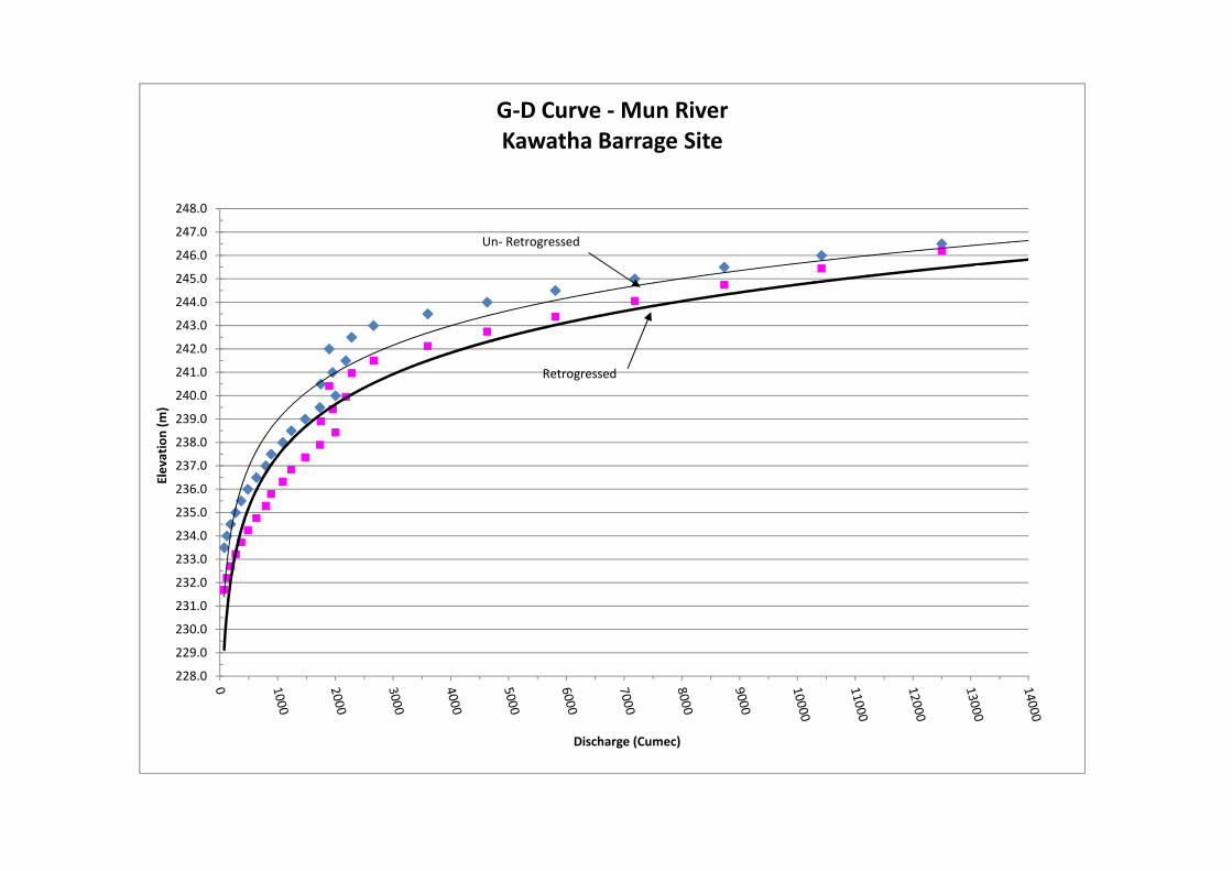
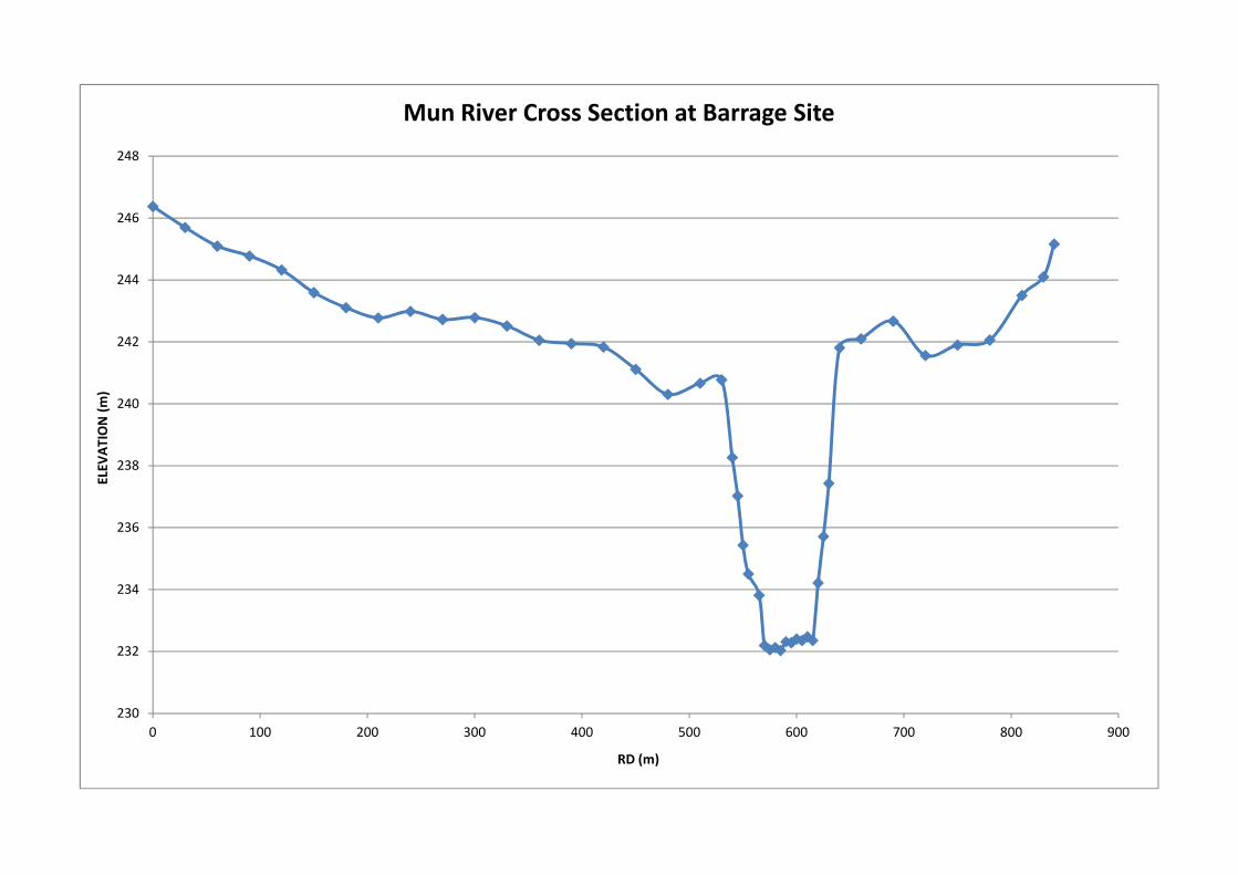
WAP/Kawatha Barrage/Akola/2011 dated 7-02-2011 in the form of report titled: Volume – II Hydrology. The inputs provided in the report were further modified vide Executive Engineer, Akola Irrigation Division, Akola letter No 3550/TS-2/Kawatha Barrage/12 dated 15-05-2012 and No. 4317/TS-2/Kawatha Barrage/ 12 dated 8-06-2012 . The main design inputs for barrage on the above basis are as follows: i. 1 in 100 yr Flood = 9149.12 say 9150 cumecs ii. F. R. L. (Pond Level) = 242.5 m iii. 1 in 500 yr Flood / SPF = 12607 cumec iv. Observed HFL corresponding to 1 in 500 yr Flood / SPF = 246.63 m v. River Bed Slope = 0.0011 vi. Average River Bed Level = 232.5 m At Pond Level, the water shall spread inside the reservoir created by the embankment Dam. Before monsoon, the gates shall be opened fully so that the design discharge may pass safely through the barrage. It is intimated by Project authorities that the farmers shall lift water from the reservoir created through lift by themselves and as such no Outlet or Head Regulator is proposed. The design of embankment dam and hydro-mechanical works is not in the scope of work of WAPCOS. In the absence of G-D curve at the barrage site, cross sectional data provided in the drawing L – Section of Barrage Line has been used for the computation of G-D Curve. Manning's coeff has been assumed as 0.03 which is given in the Hydrology report. The un-retrogressed curve has been derived as per provisions of IS 2912. The River bed slope has been taken as 0.0011 which is provided in the report titled Volume – II Hydrology mentioned above. Vide letter No. 3329/TS-6/Kawatha Barrage/ 12 dated 6-07-2012 some observed water level values along with corresponding discharges were provided by Project Authorities. However these values were dependent on the passage of discharge through a saddle portion at 0.00 RD which shall not be there after construction of
`
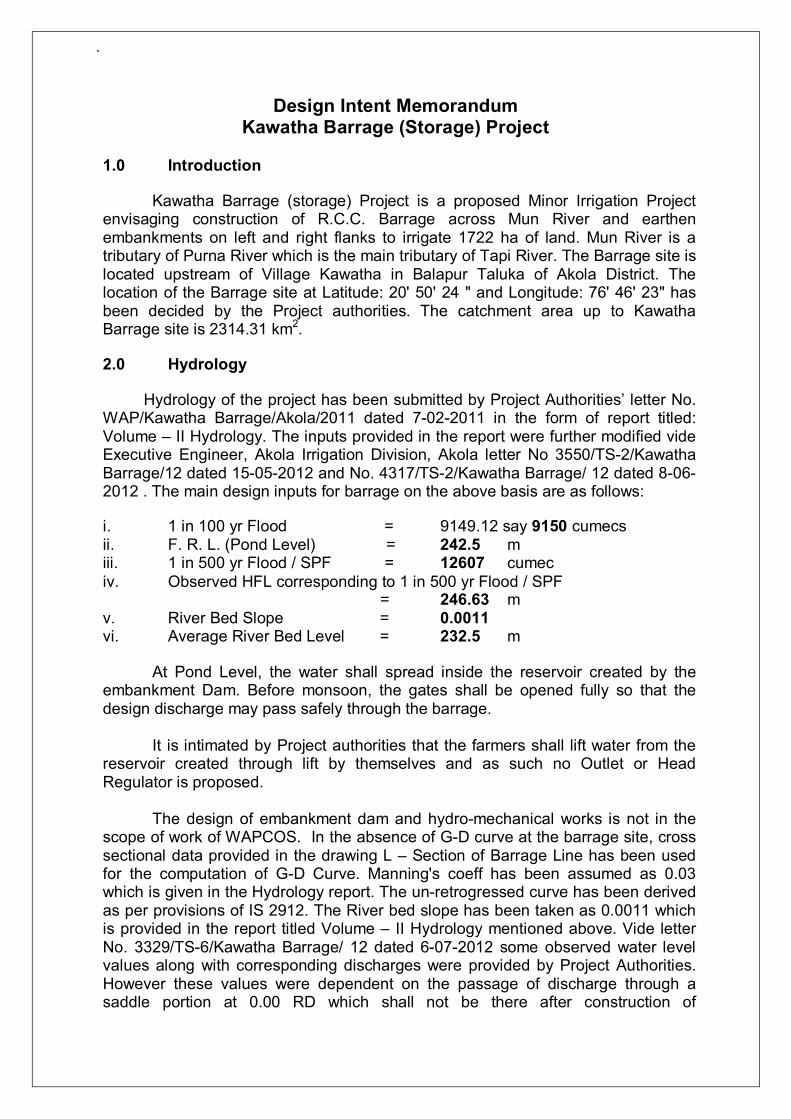
embankment dam, therefore, the G - D curve values computed as per above para were adopted for design of various components of barrage. Retrogression values of 0.3 m at high flood and 1.8 m for low discharges are adopted as per provisions of IS 6966. Following salient Water Levels (retrogressed as well as un-retrogressed) were computed on the basis of G-D curve : S. No.
Discharge (cumec)
Water Level (m) Retro Levels (m)
1 100Yr.R.F. 9150 245.63 244.93 2 500 yr R.F. 12607 246.53 246.24 3 75% 100Yr.R.F. 6862.5 244.89 243.91 4 50% 100Yr.R.F. 4575 243.98 242.72 5 25% 100Yr.R.F. 2287.5 242.52 240.98
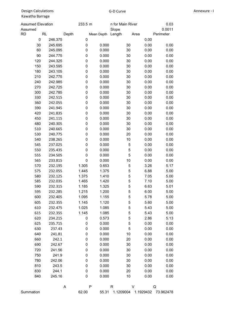
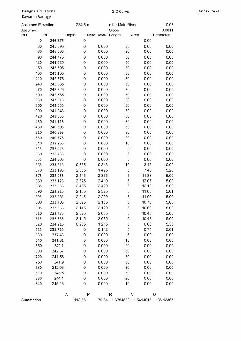
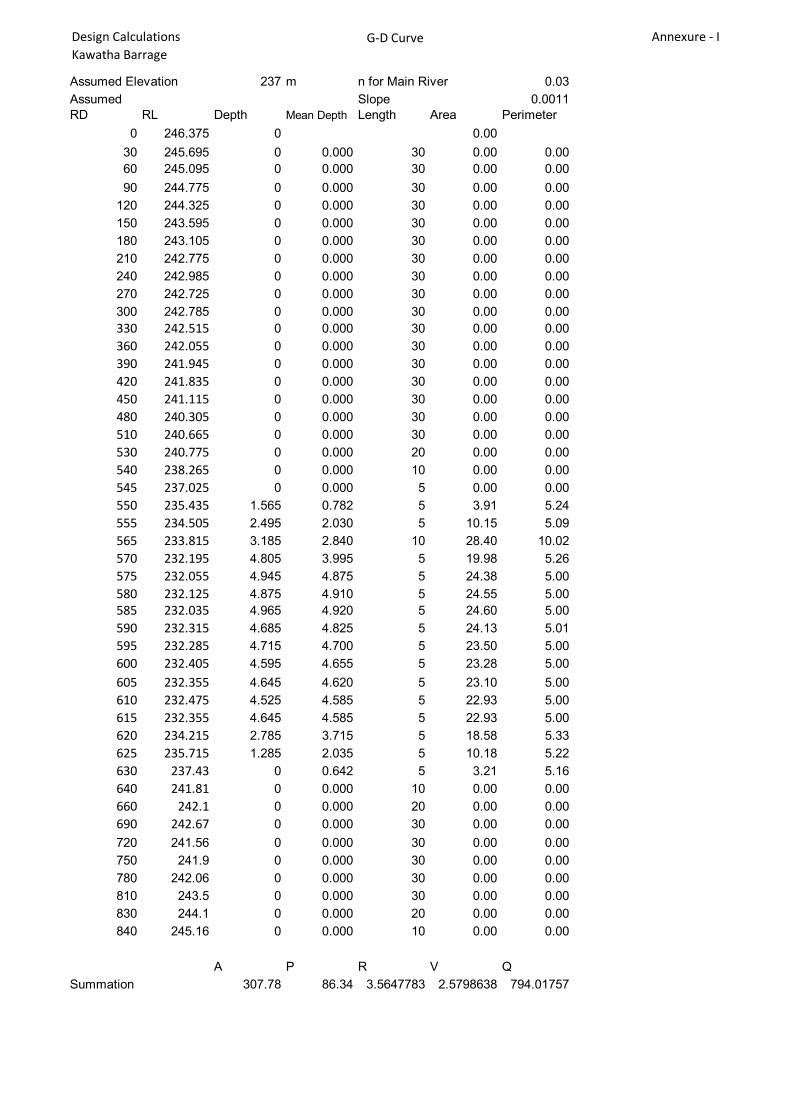
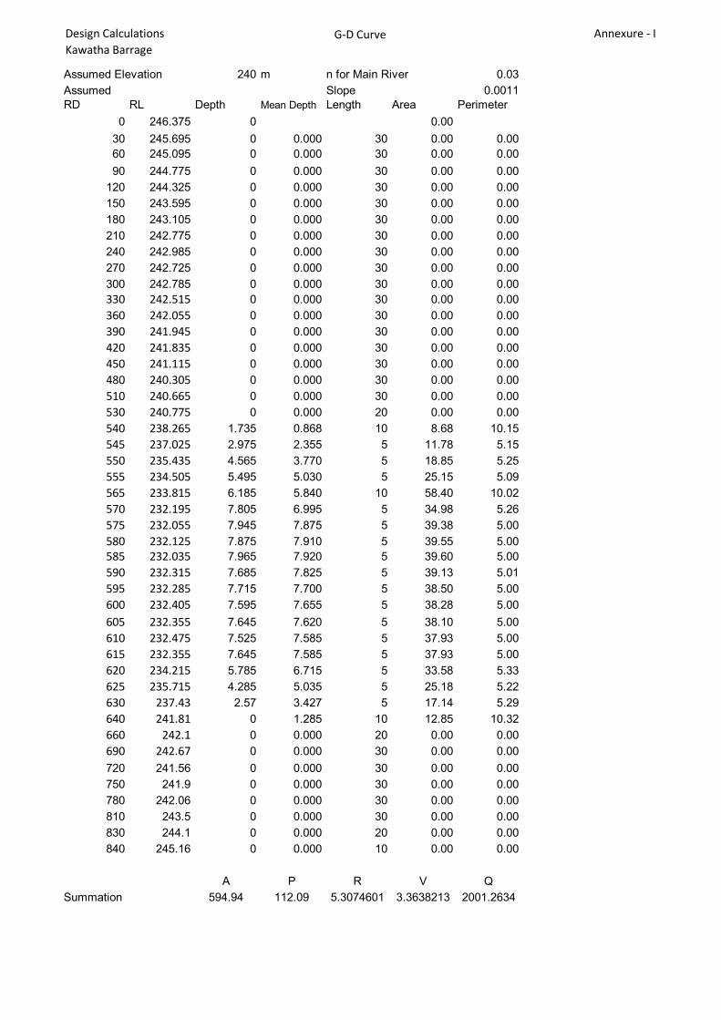
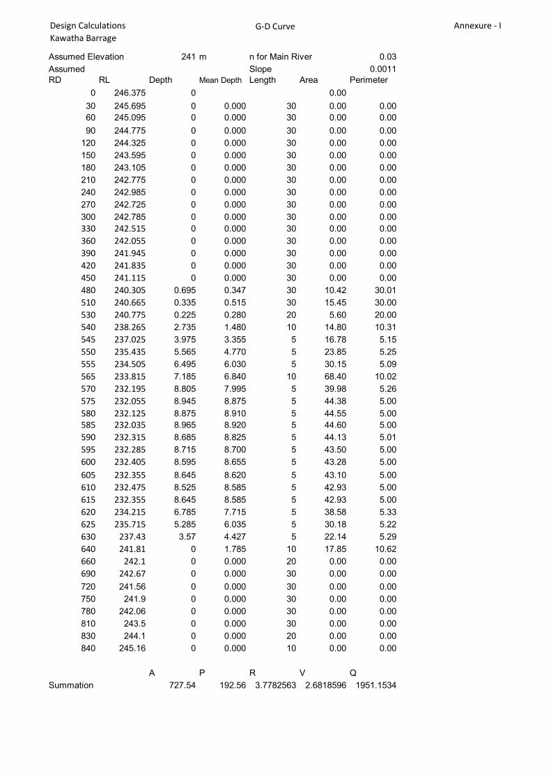
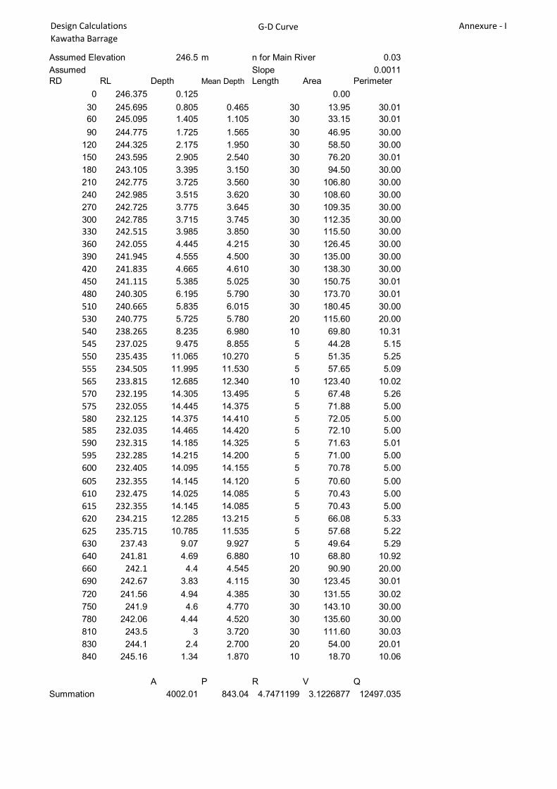
See annexure - I for the detailed calculations
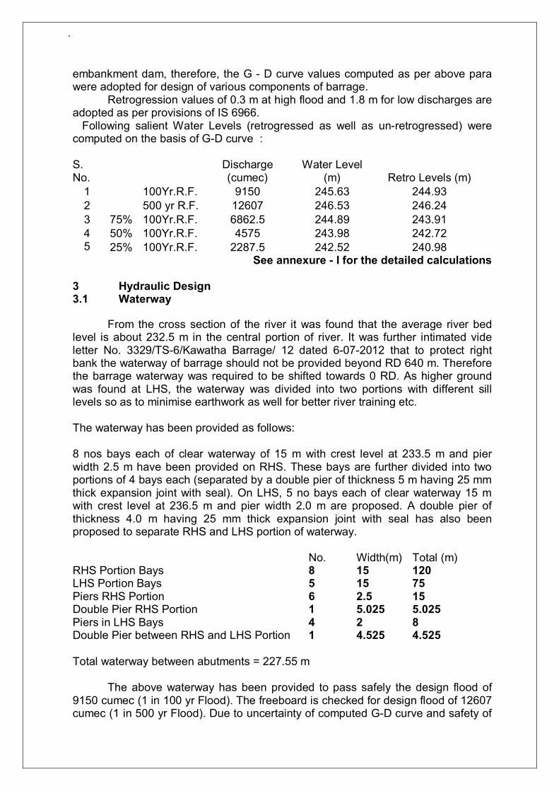
3 Hydraulic Design 3.1 Waterway From the cross section of the river it was found that the average river bed level is about 232.5 m in the central portion of river. It was further intimated vide letter No. 3329/TS-6/Kawatha Barrage/ 12 dated 6-07-2012 that to protect right bank the waterway of barrage should not be provided beyond RD 640 m. Therefore the barrage waterway was required to be shifted towards 0 RD. As higher ground was found at LHS, the waterway was divided into two portions with different sill levels so as to minimise earthwork as well for better river training etc. The waterway has been provided as follows: 8 nos bays each of clear waterway of 15 m with crest level at 233.5 m and pier width 2.5 m have been provided on RHS. These bays are further divided into two portions of 4 bays each (separated by a double pier of thickness 5 m having 25 mm thick expansion joint with seal). On LHS, 5 no bays each of clear waterway 15 m with crest level at 236.5 m and pier width 2.0 m are proposed. A double pier of thickness 4.0 m having 25 mm thick expansion joint with seal has also been proposed to separate RHS and LHS portion of waterway. No. Width(m) Total (m) RHS Portion Bays 8 15 120 LHS Portion Bays 5 15 75 Piers RHS Portion 6 2.5 15 Double Pier RHS Portion 1 5.025 5.025 Piers in LHS Bays 4 2 8 Double Pier between RHS and LHS Portion 1 4.525 4.525 Total waterway between abutments = 227.55 m The above waterway has been provided to pass safely the design flood of 9150 cumec (1 in 100 yr Flood). The freeboard is checked for design flood of 12607 cumec (1 in 500 yr Flood). Due to uncertainty of computed G-D curve and safety of

`
embankment dam provided on both sides of Barrage, the observed high flood level of 246.63 is considered for freeboard computation in place of computed value by G-D curve (which is lower than observed value at EL 246.53 m). Afflux for 1 in 100 year flood is about 0.27 m and for 1 in 500 year is about 0.75 m therefore affluxed HFL for 1 in 500 year flood is 247.38 m. It is seen from the calculations that the afflux is well within limits. Top of piers are provided with 1.52 m freeboard above this level at EL 248.9 m. The top deck level of bridge provided is further 2 m above at EL 250.9 m
See Annexure - II for detailed hydraulic calculations
3.2 Energy Dissipation Arrangement
Since rock level is very deep and barrage is founded on soil, a stilling basin has been provided to take care of excessive scouring and undermining of foundation.
The stilling basin requirement have been based on different conditions viz design discharge passing with 20% concentration and flood passing with various gate openings 1 m, 2m, 3m etc at pond level.
A condition has also been tested when 25% of design discharge (i.e. 2287.5 cum) is released from barrage through equal partial release from all gates of RHS portion and pond level is maintained on upstream.
Based on all such considerations and as per provisions of IS4997, stilling basin with cistern level at 230 m and length 30 m has been provided for RHS bays & stilling basin with cistern level at 232 m with 25 m length has been provided for LHS bays. Basin Blocks have also been provided in the basin.
See Annexure - II for detailed hydraulic calculations
3.3 Silt Factor
Silt factor has been taken as 1.09 as per value provided by Executive Engineer, Akola Irrigation Division, Akola vide letter No 3550/TS-2/Kawatha Barrage/12 dated 15/05/2012. 3.4 R.C.C. Cutoff Walls
Cut offs are barriers provided below the floor of the structure both at the upstream and downstream ends. They extend from bank to bank and also in the longitudinal direction along the flow. The main purpose of cut offs is to lengthen the seepage path below the structure and also to prevent piping action below the floor. RCC cutoffs are chosen due to relatively hard foundation strata where driving of sheet piles is difficult and sheet piles may get damaged leading to unsafe seepage flow beneath barrage.
Upstream cut off is required for safety against scour and also to reduce the seepage pressures beneath the floor. Downstream cut off is required for safety against scour and also safety against piping action. The cut offs in the longitudinal direction also known as cross cut offs provide boxing effect adding to the stability of the blocks / units of the structure. They should be continuous and leak proof. The depth to which these are taken below the floor levels depends on the safety factor adopted in the designs. As a general practice in the design of barrages and weirs on

`
permeable foundation, seepage below barrage is natural but the magnitude of seepage will depend upon the permeability of foundation strata. However the scouring, exit gradient and piping are taken care.
For safety against scour the required depth for upstream / downstream cut-
offs are EL 226.93 m (u/s) / 221.56 m (d/s) for RHS bays and 232.28 m (u/s) / 228.24 m (d/s) for LHS bays respectively. However upstream / downstream cut-offs have been provided upto the level of EL 225 m (u/s) / 221.5 m (d/s) for RHS bays and 229.0 m (u/s) / 226.2 m (d/s) for LHS bays respectively for consideration like soil strata, uplift force distribution etc. Since relatively impermeable strata may be encountered at the downstream cutoff location above EL 221.5 m and this may cause the uplift pressure to build up below the raft floor, it is proposed to provide 1200 mm thick layer of pervious material (sand) overlain by 600 thick inverted filter. Pressure release pipes shall be provided with outlet in basin blocks and end sill to safely release the water pressure. Non-return valves shall also be provided to avoid ingress of water below the raft. Cross cutoffs shall also be provided below double piers and abutments. The grade of concrete proposed for RCC cut off is M20 MSA 20.
3.5 Flexible protection works
Flexible protection works in the form of CC blocks and loose stone launching apron have been designed as per provisions of IS: 6966 on the upstream and downstream of the Barrage. The C.C. blocks of 1.5X1.5X0.9m size over 0.6m thick spawls on the upstream end of barrage floor and over 0.60m thick inverted filter and partly over 0.60m spawls have been provided on the downstream side of RCC floor.. The C.C. blocks on upstream and downstream end are provided to cater scour 1.5R and 2.0R for a length of 1D and 1.5D, where ‘D’ is the depth of scour below apron level and ‘R’ is the normal Lacey’s scour depth. Beyond C.C. blocks protection with loose stone apron both on the upstream and downstream ends have been provided. While computing the requirements of this loose stone apron, launching slope of 2:1 has been considered. The protections works are designed for a design flood corresponding to 9150 cumecs. This protection works form first line of defence for the barrage against scouring and shall need monitoring, maintenance and renewal as per requirement after every flood season. 3.6 Looseness Factor:
The looseness factor has been worked out to be 0.5. 3.7 Exit Gradient:
The foundation strata consists mainly of alluvial deposits and conglomerates. The fresh (hard) rock is encountered at considerable depth. The cut-offs have been taken up to El 225.00 m (u/s) / EL 221.5 m (d/s) for RHS bays and 229.0 m (u/s) / 226.2 m (d/s) against scour, seepage and exit gradient condition. With this arrangements, the exit gradient worked out as per Khosla’s formula is more than 1 in 6 against the safe exit gradient of 1 in 6 to 7 as per IS:6966.
For Hydraulic Design refer Annexure-II.

`
4.0 Raft Floor
R.C.C raft foundation has been provided due to following considerations. i. The soil below foundation is having low safe bearing capacity. By combining
the footings of piers with raft, the unit pressure on the soil below piers get redistributed due to redistribution of pressure over raft.
ii. If random distribution of compressive zones exists in the soil foundation, raft structure acts as a bridge over the compressible zones and the differential settlements are minimized.
iii. A raft floor takes advantage of the weight of piers to resist the uplift pressure. iv. In seismic areas as in the present case raft foundation is structurally superior
in comparison of gravity floor with large thickness which is more vulnerable to cracking. The piers and abutments/ end piers are constructed monolithically in RCC M20 MSA40. For the purpose of structural design of raft: it would be divided into various zones depending on the intensity of loading transferred to the raft from external loading through piers. The raft would be designed as beam on elastic foundation.
Earthquake Forces:
According to IS:1893-2002 classifications, the location of the barrage falls under Earth Quake Zone-III. The design horizontal acceleration coefficient according to the above codes is 0.12 and vertical acceleration is 0.08. The earthquake forces are analyzed with the seismic coefficient method.
The following forces have been considered for the analysis and design of raft. (i) Dead Loads of Gantry cum Road bridge, piers and raft. (ii) Live Load due to Gantry cum Road Bridge IRC class A (iii) Impact and breaking effects of live loads (iv) Temperature forces transmitted through bridge bearings (v) Dead and live load of gates, stoplogs counter weights and hoist bridge (vi) Braking effect of gantry crane (vii) Buoyancy (viii) Differential hydrostatic pressure with one gate open and other adjacent gate
closed (ix) Seismic forces and moments and (x) Hydrodynamic forces due to earthquake. To resist the worst combination of the above forces and moments raft
thickness of 2.5m for RHS and 2.0 m for LHS portion is proposed. 5.0 Stability Analysis 5.1 Piers & Abutments
The top of the piers has been kept at EL248.9 to hold the gates clear off the maximum flood while making ample allowance for passing the floating debris under the gate. The height of the piers in the zone away from Gate Bridge and Gantry cum road bridge zones have been reduced as per dispersion requirement of loads. On downstream side the pier height is reduced from 248.9 to 238.5 m in incremental way allowing partial submergence of the piers on d/s and no submergence on u/s under pond level condition. The height of the piers away from gate bridge and gantry bridge is kept as minimum as possible and extended upto the ends of raft for
`
countering the uplift, to avoid excessive cantilever action of raft and dead weight requirement while computing the overall stability of the structure. The barrage is divided into three units with 4+4+5 bays. Each unit is separated from other with a double pier. The units localize the settlements if any and allow expansion and make easy of construction. 5.2 Stability
The stability of gated barrage is checked against sliding, floating during flood condition and overturning for both non earth quake and earth quake conditions as per IS:6512. The factor of safety against sliding are more than the desired safe values of 1.5 and 1.2 respectively. For all possible combination of forces the resultant falls within the middle third and it is safe against overturning and tension. The maximum base pressures worked out for NEQ and EQ conditions are below the safe bearing pressure. The factor of safety against floating under flood condition is adequate.
6.0 Flared out Walls/ Flank Walls/ Guide Bunds
In continuation of the abutments, flank walls are provided on the upstream and downstream side. The flank walls ensure smooth entry and exit of water from diversion structure. Guide bunds are provided beyond flank walls to further train the inflow and outflow of discharge through barrage. These details are being worked out and are tentatively shown in the drawings. 7.0 Geotechnical Investigation:
The Geotechnical investigation were carried out by Project authorities. The
following reports prepared by Project Authorities were forwarded to WAPCOS: 1. Geotechnical Report, Geological Division, CDO, Nasik 2. Revised Geotechnical Report prepared by M/S Shreya Services, Nagpur
8.0 Bridge:
A single Lane Gantry cum Road Bridge for class 'A' loading without foot-path is provided on the barrage portion. The width of bridge is taken as 6.5 m to accommodate the gantry. The bridge deck top level is provided at 250.9 m whereas the embankment top may be kept at EL 248.9 m Therefore, in continuation of this bridge, approaches for app. Length of 40 m on embankments dam top with 1 in 20 slope may be provided to connect the bridge deck level with embankment top level as per actual site conditions. The embankment Dam top width may also be reduced from 6.5 m to required top width in this transition zone as per actual site conditions.

`
References 1. IS: 2912:1999 Liquid Flow Measurements in Open Channels - Slope-Area
Method. 2. IS:4997:1968 Criteria for design of hydraulic jump type stilling basins with horizontal and sloping apron 3. IS: 6512: 1984 Criteria for design of solid gravity dams. 4. IS: 6966-Part 1: 1989 Guidelines for hydraulic design of barrages and weirs:
Part 1 Alluvial Reaches. 5. IS:14344-Design and construction of Diaphragm for under seepage Control-
Code of Practice. 6. CBIP Publication No.179_Manual on Barrages and Weirs on Permeable
Foundation Vol-I&II. 7. M. Hetenyi-Beams on Elastic Foundation. 8. IRC-5-Standard Specifications and code of practice for Road Bridges-
Section I-General Features. 9. IRC-6- Standard Specifications and code of practice for Road Bridges-
Section II-Loads and Stresses.
Un- Retrogressed
Retrogressed
228.0
229.0
230.0
231.0
232.0
233.0
234.0
235.0
236.0
237.0
238.0
239.0
240.0
241.0
242.0
243.0
244.0
245.0
246.0
247.0
248.0
Elev
atio
n (m
)
Discharge (Cumec)
G-D Curve - Mun River Kawatha Barrage Site
230
232
234
236
238
240
242
244
246
248
0 100 200 300 400 500 600 700 800 900
ELEV
ATIO
N (m
)
RD (m)
Mun River Cross Section at Barrage Site

Design CalculationsKawatha Barrage
G-D Curve Annexure - I
G-D Curve Mun River at Proposed Barrage site
Area P R Avg. Vel. Q233.5 62.00 55.31 1.12 1.19 73.96 1.8 231.70234.0 88.39 65.54 1.35 1.35 119.28 1.79 232.21234.5 118.56 70.64 1.68 1.56 185.12 1.79 232.71235.0 153.53 75.72 2.03 1.77 271.90 1.78 233.22235.5 188.85 80.88 2.33 1.95 367.46 1.76 233.74236.0 227.78 85.98 2.65 2.12 482.13 1.75 234.25236.5 267.78 86.11 3.11 2.36 630.70 1.73 234.77237.0 307.78 86.34 3.56 2.58 794.02 1.71 235.29237.5 350.68 101.49 3.46 2.53 886.06 1.70 235.80238.0 396.93 101.58 3.91 2.74 1088.64 1.68 236.32238.5 444.94 111.68 3.98 2.78 1236.20 1.66 236.84239.0 494.94 111.77 4.43 2.98 1475.51 1.63 237.37239.5 544.94 111.91 4.87 3.18 1730.79 1.60 237.90240.0 594.94 112.09 5.31 3.36 2001.26 1.57 238.43240.5 650.79 172.33 3.78 2.68 1744.76 1.60 238.90241.0 727.54 192.56 3.78 2.68 1951.15 1.57 239.43241.5 824.09 222.74 3.70 2.64 2179.36 1.55 239.95242.0 949.74 392.88 2.42 1.99 1891.23 1.58 240.42242.5 1153.79 482.90 2.39 1.98 2279.72 1.53 240.97243.0 1410.14 632.92 2.23 1.89 2659.36 1.49 241.51243.5 1721.99 662.95 2.60 2.09 3597.27 1.37 242.13244.0 2061.64 712.96 2.89 2.24 4626.16 1.25 242.75244.5 2415.39 752.97 3.21 2.40 5808.09 1.11 243.39245.0 2787.14 783.01 3.56 2.58 7183.36 0.94 244.06245.5 3180.99 813.03 3.91 2.75 8731.88 0.75 244.75246.0 3587.64 843.03 4.26 2.90 10415.80 0.55 245.45246.5 4002.01 843.04 4.75 3.12 12497.04 0.30 246.20247.0 4422.01 843.04 5.25 3.34 14758.52 0.2 246.80
Assuming N = 0.03 Slope = 0.0011Computed Water Levels are: W.L.
Q (cumec) Un-Retro. W. L. (m) Retro. W. L. (m) Observed 100Yr.R.F. 9150 245.63 244.93 (m)500 Yr R.F. 12607.09 246.53 246.24 246.63
75% of 100Yr.R.F. 6862.5 244.89 243.9150% of 100Yr.R.F. 4575 243.98 242.72
25% of 100Yr.R.F. 2287.5 242.52 240.98
Discharge at FRL* 2606.22 242.94Discharge at HFL* 5445.1 244.35
* Communicated vide Exective engineer, akola Irrigation Division vide letter No 4317/TS-2/Kawatha Barrage/12 Dated 8/6/2012
Water Level
Mun River Retro- gression Retro levels
Design CalculationsKawatha Barrage
G-D Curve Annexure - I
Assumed Elevation 233.5 m n for Main River 0.03Assumed Slope 0.0011RD RL Depth Mean Depth Length Area Perimeter
0 246.375 0 0.0030 245.695 0 0.000 30 0.00 0.0060 245.095 0 0.000 30 0.00 0.0090 244.775 0 0.000 30 0.00 0.00
120 244.325 0 0.000 30 0.00 0.00150 243.595 0 0.000 30 0.00 0.00180 243.105 0 0.000 30 0.00 0.00210 242.775 0 0.000 30 0.00 0.00240 242.985 0 0.000 30 0.00 0.00270 242.725 0 0.000 30 0.00 0.00300 242.785 0 0.000 30 0.00 0.00330 242.515 0 0.000 30 0.00 0.00360 242.055 0 0.000 30 0.00 0.00390 241.945 0 0.000 30 0.00 0.00420 241.835 0 0.000 30 0.00 0.00450 241.115 0 0.000 30 0.00 0.00480 240.305 0 0.000 30 0.00 0.00510 240.665 0 0.000 30 0.00 0.00530 240.775 0 0.000 20 0.00 0.00540 238.265 0 0.000 10 0.00 0.00545 237.025 0 0.000 5 0.00 0.00550 235.435 0 0.000 5 0.00 0.00555 234.505 0 0.000 5 0.00 0.00565 233.815 0 0.000 10 0.00 0.00570 232.195 1.305 0.653 5 3.26 5.17575 232.055 1.445 1.375 5 6.88 5.00580 232.125 1.375 1.410 5 7.05 5.00585 232.035 1.465 1.420 5 7.10 5.00590 232.315 1.185 1.325 5 6.63 5.01595 232.285 1.215 1.200 5 6.00 5.00600 232.405 1.095 1.155 5 5.78 5.00605 232.355 1.145 1.120 5 5.60 5.00610 232.475 1.025 1.085 5 5.43 5.00615 232.355 1.145 1.085 5 5.43 5.00620 234.215 0 0.573 5 2.86 5.13625 235.715 0 0.000 5 0.00 0.00630 237.43 0 0.000 5 0.00 0.00640 241.81 0 0.000 10 0.00 0.00660 242.1 0 0.000 20 0.00 0.00690 242.67 0 0.000 30 0.00 0.00720 241.56 0 0.000 30 0.00 0.00750 241.9 0 0.000 30 0.00 0.00780 242.06 0 0.000 30 0.00 0.00810 243.5 0 0.000 30 0.00 0.00830 244.1 0 0.000 20 0.00 0.00840 245.16 0 0.000 10 0.00 0.00
A P R V QSummation 62.00 55.31 1.1209004 1.1929432 73.962478

Design CalculationsKawatha Barrage
G-D Curve Annexure - I
Assumed Elevation 234 m n for Main River 0.03Assumed Slope 0.0011RD RL Depth Mean Depth Length Area Perimeter
0 246.375 0 0.0030 245.695 0 0.000 30 0.00 0.0060 245.095 0 0.000 30 0.00 0.0090 244.775 0 0.000 30 0.00 0.00
120 244.325 0 0.000 30 0.00 0.00150 243.595 0 0.000 30 0.00 0.00180 243.105 0 0.000 30 0.00 0.00210 242.775 0 0.000 30 0.00 0.00240 242.985 0 0.000 30 0.00 0.00270 242.725 0 0.000 30 0.00 0.00300 242.785 0 0.000 30 0.00 0.00330 242.515 0 0.000 30 0.00 0.00360 242.055 0 0.000 30 0.00 0.00390 241.945 0 0.000 30 0.00 0.00420 241.835 0 0.000 30 0.00 0.00450 241.115 0 0.000 30 0.00 0.00480 240.305 0 0.000 30 0.00 0.00510 240.665 0 0.000 30 0.00 0.00530 240.775 0 0.000 20 0.00 0.00540 238.265 0 0.000 10 0.00 0.00545 237.025 0 0.000 5 0.00 0.00550 235.435 0 0.000 5 0.00 0.00555 234.505 0 0.000 5 0.00 0.00565 233.815 0.185 0.093 10 0.93 10.00570 232.195 1.805 0.995 5 4.98 5.26575 232.055 1.945 1.875 5 9.38 5.00580 232.125 1.875 1.910 5 9.55 5.00585 232.035 1.965 1.920 5 9.60 5.00590 232.315 1.685 1.825 5 9.13 5.01595 232.285 1.715 1.700 5 8.50 5.00600 232.405 1.595 1.655 5 8.28 5.00605 232.355 1.645 1.620 5 8.10 5.00610 232.475 1.525 1.585 5 7.93 5.00615 232.355 1.645 1.585 5 7.93 5.00620 234.215 0 0.823 5 4.11 5.26625 235.715 0 0.000 5 0.00 0.00630 237.43 0 0.000 5 0.00 0.00640 241.81 0 0.000 10 0.00 0.00660 242.1 0 0.000 20 0.00 0.00690 242.67 0 0.000 30 0.00 0.00720 241.56 0 0.000 30 0.00 0.00750 241.9 0 0.000 30 0.00 0.00780 242.06 0 0.000 30 0.00 0.00810 243.5 0 0.000 30 0.00 0.00830 244.1 0 0.000 20 0.00 0.00840 245.16 0 0.000 10 0.00 0.00
A P R V QSummation 88.39 65.54 1.3486655 1.3495156 119.28031
Design CalculationsKawatha Barrage
G-D Curve Annexure - I
Assumed Elevation 234.5 m n for Main River 0.03Assumed Slope 0.0011RD RL Depth Mean Depth Length Area Perimeter
0 246.375 0 0.0030 245.695 0 0.000 30 0.00 0.0060 245.095 0 0.000 30 0.00 0.0090 244.775 0 0.000 30 0.00 0.00
120 244.325 0 0.000 30 0.00 0.00150 243.595 0 0.000 30 0.00 0.00180 243.105 0 0.000 30 0.00 0.00210 242.775 0 0.000 30 0.00 0.00240 242.985 0 0.000 30 0.00 0.00270 242.725 0 0.000 30 0.00 0.00300 242.785 0 0.000 30 0.00 0.00330 242.515 0 0.000 30 0.00 0.00360 242.055 0 0.000 30 0.00 0.00390 241.945 0 0.000 30 0.00 0.00420 241.835 0 0.000 30 0.00 0.00450 241.115 0 0.000 30 0.00 0.00480 240.305 0 0.000 30 0.00 0.00510 240.665 0 0.000 30 0.00 0.00530 240.775 0 0.000 20 0.00 0.00540 238.265 0 0.000 10 0.00 0.00545 237.025 0 0.000 5 0.00 0.00550 235.435 0 0.000 5 0.00 0.00555 234.505 0 0.000 5 0.00 0.00565 233.815 0.685 0.343 10 3.43 10.02570 232.195 2.305 1.495 5 7.48 5.26575 232.055 2.445 2.375 5 11.88 5.00580 232.125 2.375 2.410 5 12.05 5.00585 232.035 2.465 2.420 5 12.10 5.00590 232.315 2.185 2.325 5 11.63 5.01595 232.285 2.215 2.200 5 11.00 5.00600 232.405 2.095 2.155 5 10.78 5.00605 232.355 2.145 2.120 5 10.60 5.00610 232.475 2.025 2.085 5 10.43 5.00615 232.355 2.145 2.085 5 10.43 5.00620 234.215 0.285 1.215 5 6.08 5.33625 235.715 0 0.142 5 0.71 5.01630 237.43 0 0.000 5 0.00 0.00640 241.81 0 0.000 10 0.00 0.00660 242.1 0 0.000 20 0.00 0.00690 242.67 0 0.000 30 0.00 0.00720 241.56 0 0.000 30 0.00 0.00750 241.9 0 0.000 30 0.00 0.00780 242.06 0 0.000 30 0.00 0.00810 243.5 0 0.000 30 0.00 0.00830 244.1 0 0.000 20 0.00 0.00840 245.16 0 0.000 10 0.00 0.00
A P R V QSummation 118.56 70.64 1.6784533 1.5614015 185.12367

Design CalculationsKawatha Barrage
G-D Curve Annexure - I
Assumed Elevation 235 m n for Main River 0.03Assumed Slope 0.0011RD RL Depth Mean Depth Length Area Perimeter
0 246.375 0 0.0030 245.695 0 0.000 30 0.00 0.0060 245.095 0 0.000 30 0.00 0.0090 244.775 0 0.000 30 0.00 0.00
120 244.325 0 0.000 30 0.00 0.00150 243.595 0 0.000 30 0.00 0.00180 243.105 0 0.000 30 0.00 0.00210 242.775 0 0.000 30 0.00 0.00240 242.985 0 0.000 30 0.00 0.00270 242.725 0 0.000 30 0.00 0.00300 242.785 0 0.000 30 0.00 0.00330 242.515 0 0.000 30 0.00 0.00360 242.055 0 0.000 30 0.00 0.00390 241.945 0 0.000 30 0.00 0.00420 241.835 0 0.000 30 0.00 0.00450 241.115 0 0.000 30 0.00 0.00480 240.305 0 0.000 30 0.00 0.00510 240.665 0 0.000 30 0.00 0.00530 240.775 0 0.000 20 0.00 0.00540 238.265 0 0.000 10 0.00 0.00545 237.025 0 0.000 5 0.00 0.00550 235.435 0 0.000 5 0.00 0.00555 234.505 0.495 0.248 5 1.24 5.02565 233.815 1.185 0.840 10 8.40 10.02570 232.195 2.805 1.995 5 9.98 5.26575 232.055 2.945 2.875 5 14.38 5.00580 232.125 2.875 2.910 5 14.55 5.00585 232.035 2.965 2.920 5 14.60 5.00590 232.315 2.685 2.825 5 14.13 5.01595 232.285 2.715 2.700 5 13.50 5.00600 232.405 2.595 2.655 5 13.28 5.00605 232.355 2.645 2.620 5 13.10 5.00610 232.475 2.525 2.585 5 12.93 5.00615 232.355 2.645 2.585 5 12.93 5.00620 234.215 0.785 1.715 5 8.58 5.33625 235.715 0 0.392 5 1.96 5.06630 237.43 0 0.000 5 0.00 0.00640 241.81 0 0.000 10 0.00 0.00660 242.1 0 0.000 20 0.00 0.00690 242.67 0 0.000 30 0.00 0.00720 241.56 0 0.000 30 0.00 0.00750 241.9 0 0.000 30 0.00 0.00780 242.06 0 0.000 30 0.00 0.00810 243.5 0 0.000 30 0.00 0.00830 244.1 0 0.000 20 0.00 0.00840 245.16 0 0.000 10 0.00 0.00
A P R V QSummation 153.53 75.72 2.0276464 1.7710734 271.90405

Design CalculationsKawatha Barrage
G-D Curve Annexure - I
Assumed Elevation 235.5 m n for Main River 0.03Assumed Slope 0.0011RD RL Depth Mean Depth Length Area Perimeter
0 246.375 0 0.0030 245.695 0 0.000 30 0.00 0.0060 245.095 0 0.000 30 0.00 0.0090 244.775 0 0.000 30 0.00 0.00
120 244.325 0 0.000 30 0.00 0.00150 243.595 0 0.000 30 0.00 0.00180 243.105 0 0.000 30 0.00 0.00210 242.775 0 0.000 30 0.00 0.00240 242.985 0 0.000 30 0.00 0.00270 242.725 0 0.000 30 0.00 0.00300 242.785 0 0.000 30 0.00 0.00330 242.515 0 0.000 30 0.00 0.00360 242.055 0 0.000 30 0.00 0.00390 241.945 0 0.000 30 0.00 0.00420 241.835 0 0.000 30 0.00 0.00450 241.115 0 0.000 30 0.00 0.00480 240.305 0 0.000 30 0.00 0.00510 240.665 0 0.000 30 0.00 0.00530 240.775 0 0.000 20 0.00 0.00540 238.265 0 0.000 10 0.00 0.00545 237.025 0 0.000 5 0.00 0.00550 235.435 0.065 0.032 5 0.16 5.00555 234.505 0.995 0.530 5 2.65 5.09565 233.815 1.685 1.340 10 13.40 10.02570 232.195 3.305 2.495 5 12.48 5.26575 232.055 3.445 3.375 5 16.88 5.00580 232.125 3.375 3.410 5 17.05 5.00585 232.035 3.465 3.420 5 17.10 5.00590 232.315 3.185 3.325 5 16.63 5.01595 232.285 3.215 3.200 5 16.00 5.00600 232.405 3.095 3.155 5 15.78 5.00605 232.355 3.145 3.120 5 15.60 5.00610 232.475 3.025 3.085 5 15.43 5.00615 232.355 3.145 3.085 5 15.43 5.00620 234.215 1.285 2.215 5 11.08 5.33625 235.715 0 0.642 5 3.21 5.16630 237.43 0 0.000 5 0.00 0.00640 241.81 0 0.000 10 0.00 0.00660 242.1 0 0.000 20 0.00 0.00690 242.67 0 0.000 30 0.00 0.00720 241.56 0 0.000 30 0.00 0.00750 241.9 0 0.000 30 0.00 0.00780 242.06 0 0.000 30 0.00 0.00810 243.5 0 0.000 30 0.00 0.00830 244.1 0 0.000 20 0.00 0.00840 245.16 0 0.000 10 0.00 0.00
A P R V QSummation 188.85 80.88 2.3349743 1.9457923 367.46288

Design CalculationsKawatha Barrage
G-D Curve Annexure - I
Assumed Elevation 236 m n for Main River 0.03Assumed Slope 0.0011RD RL Depth Mean Depth Length Area Perimeter
0 246.375 0 0.0030 245.695 0 0.000 30 0.00 0.0060 245.095 0 0.000 30 0.00 0.0090 244.775 0 0.000 30 0.00 0.00
120 244.325 0 0.000 30 0.00 0.00150 243.595 0 0.000 30 0.00 0.00180 243.105 0 0.000 30 0.00 0.00210 242.775 0 0.000 30 0.00 0.00240 242.985 0 0.000 30 0.00 0.00270 242.725 0 0.000 30 0.00 0.00300 242.785 0 0.000 30 0.00 0.00330 242.515 0 0.000 30 0.00 0.00360 242.055 0 0.000 30 0.00 0.00390 241.945 0 0.000 30 0.00 0.00420 241.835 0 0.000 30 0.00 0.00450 241.115 0 0.000 30 0.00 0.00480 240.305 0 0.000 30 0.00 0.00510 240.665 0 0.000 30 0.00 0.00530 240.775 0 0.000 20 0.00 0.00540 238.265 0 0.000 10 0.00 0.00545 237.025 0 0.000 5 0.00 0.00550 235.435 0.565 0.282 5 1.41 5.03555 234.505 1.495 1.030 5 5.15 5.09565 233.815 2.185 1.840 10 18.40 10.02570 232.195 3.805 2.995 5 14.98 5.26575 232.055 3.945 3.875 5 19.38 5.00580 232.125 3.875 3.910 5 19.55 5.00585 232.035 3.965 3.920 5 19.60 5.00590 232.315 3.685 3.825 5 19.13 5.01595 232.285 3.715 3.700 5 18.50 5.00600 232.405 3.595 3.655 5 18.28 5.00605 232.355 3.645 3.620 5 18.10 5.00610 232.475 3.525 3.585 5 17.93 5.00615 232.355 3.645 3.585 5 17.93 5.00620 234.215 1.785 2.715 5 13.58 5.33625 235.715 0.285 1.035 5 5.17 5.22630 237.43 0 0.142 5 0.71 5.01640 241.81 0 0.000 10 0.00 0.00660 242.1 0 0.000 20 0.00 0.00690 242.67 0 0.000 30 0.00 0.00720 241.56 0 0.000 30 0.00 0.00750 241.9 0 0.000 30 0.00 0.00780 242.06 0 0.000 30 0.00 0.00810 243.5 0 0.000 30 0.00 0.00830 244.1 0 0.000 20 0.00 0.00840 245.16 0 0.000 10 0.00 0.00
A P R V QSummation 227.78 85.98 2.6492852 2.1167077 482.13311

Design CalculationsKawatha Barrage
G-D Curve Annexure - I
Assumed Elevation 236.5 m n for Main River 0.03Assumed Slope 0.0011RD RL Depth Mean Depth Length Area Perimeter
0 246.375 0 0.0030 245.695 0 0.000 30 0.00 0.0060 245.095 0 0.000 30 0.00 0.0090 244.775 0 0.000 30 0.00 0.00
120 244.325 0 0.000 30 0.00 0.00150 243.595 0 0.000 30 0.00 0.00180 243.105 0 0.000 30 0.00 0.00210 242.775 0 0.000 30 0.00 0.00240 242.985 0 0.000 30 0.00 0.00270 242.725 0 0.000 30 0.00 0.00300 242.785 0 0.000 30 0.00 0.00330 242.515 0 0.000 30 0.00 0.00360 242.055 0 0.000 30 0.00 0.00390 241.945 0 0.000 30 0.00 0.00420 241.835 0 0.000 30 0.00 0.00450 241.115 0 0.000 30 0.00 0.00480 240.305 0 0.000 30 0.00 0.00510 240.665 0 0.000 30 0.00 0.00530 240.775 0 0.000 20 0.00 0.00540 238.265 0 0.000 10 0.00 0.00545 237.025 0 0.000 5 0.00 0.00550 235.435 1.065 0.532 5 2.66 5.11555 234.505 1.995 1.530 5 7.65 5.09565 233.815 2.685 2.340 10 23.40 10.02570 232.195 4.305 3.495 5 17.48 5.26575 232.055 4.445 4.375 5 21.88 5.00580 232.125 4.375 4.410 5 22.05 5.00585 232.035 4.465 4.420 5 22.10 5.00590 232.315 4.185 4.325 5 21.63 5.01595 232.285 4.215 4.200 5 21.00 5.00600 232.405 4.095 4.155 5 20.78 5.00605 232.355 4.145 4.120 5 20.60 5.00610 232.475 4.025 4.085 5 20.43 5.00615 232.355 4.145 4.085 5 20.43 5.00620 234.215 2.285 3.215 5 16.08 5.33625 235.715 0.785 1.535 5 7.67 5.22630 237.43 0 0.392 5 1.96 5.06640 241.81 0 0.000 10 0.00 0.00660 242.1 0 0.000 20 0.00 0.00690 242.67 0 0.000 30 0.00 0.00720 241.56 0 0.000 30 0.00 0.00750 241.9 0 0.000 30 0.00 0.00780 242.06 0 0.000 30 0.00 0.00810 243.5 0 0.000 30 0.00 0.00830 244.1 0 0.000 20 0.00 0.00840 245.16 0 0.000 10 0.00 0.00
A P R V QSummation 267.78 86.11 3.1097035 2.3553444 630.70234
Design CalculationsKawatha Barrage
G-D Curve Annexure - I
Assumed Elevation 237 m n for Main River 0.03Assumed Slope 0.0011RD RL Depth Mean Depth Length Area Perimeter
0 246.375 0 0.0030 245.695 0 0.000 30 0.00 0.0060 245.095 0 0.000 30 0.00 0.0090 244.775 0 0.000 30 0.00 0.00
120 244.325 0 0.000 30 0.00 0.00150 243.595 0 0.000 30 0.00 0.00180 243.105 0 0.000 30 0.00 0.00210 242.775 0 0.000 30 0.00 0.00240 242.985 0 0.000 30 0.00 0.00270 242.725 0 0.000 30 0.00 0.00300 242.785 0 0.000 30 0.00 0.00330 242.515 0 0.000 30 0.00 0.00360 242.055 0 0.000 30 0.00 0.00390 241.945 0 0.000 30 0.00 0.00420 241.835 0 0.000 30 0.00 0.00450 241.115 0 0.000 30 0.00 0.00480 240.305 0 0.000 30 0.00 0.00510 240.665 0 0.000 30 0.00 0.00530 240.775 0 0.000 20 0.00 0.00540 238.265 0 0.000 10 0.00 0.00545 237.025 0 0.000 5 0.00 0.00550 235.435 1.565 0.782 5 3.91 5.24555 234.505 2.495 2.030 5 10.15 5.09565 233.815 3.185 2.840 10 28.40 10.02570 232.195 4.805 3.995 5 19.98 5.26575 232.055 4.945 4.875 5 24.38 5.00580 232.125 4.875 4.910 5 24.55 5.00585 232.035 4.965 4.920 5 24.60 5.00590 232.315 4.685 4.825 5 24.13 5.01595 232.285 4.715 4.700 5 23.50 5.00600 232.405 4.595 4.655 5 23.28 5.00605 232.355 4.645 4.620 5 23.10 5.00610 232.475 4.525 4.585 5 22.93 5.00615 232.355 4.645 4.585 5 22.93 5.00620 234.215 2.785 3.715 5 18.58 5.33625 235.715 1.285 2.035 5 10.18 5.22630 237.43 0 0.642 5 3.21 5.16640 241.81 0 0.000 10 0.00 0.00660 242.1 0 0.000 20 0.00 0.00690 242.67 0 0.000 30 0.00 0.00720 241.56 0 0.000 30 0.00 0.00750 241.9 0 0.000 30 0.00 0.00780 242.06 0 0.000 30 0.00 0.00810 243.5 0 0.000 30 0.00 0.00830 244.1 0 0.000 20 0.00 0.00840 245.16 0 0.000 10 0.00 0.00
A P R V QSummation 307.78 86.34 3.5647783 2.5798638 794.01757

Design CalculationsKawatha Barrage
G-D Curve Annexure - I
Assumed Elevation 237.5 m n for Main River 0.03Assumed Slope 0.0011RD RL Depth Mean Depth Length Area Perimeter
0 246.375 0 0.0030 245.695 0 0.000 30 0.00 0.0060 245.095 0 0.000 30 0.00 0.0090 244.775 0 0.000 30 0.00 0.00
120 244.325 0 0.000 30 0.00 0.00150 243.595 0 0.000 30 0.00 0.00180 243.105 0 0.000 30 0.00 0.00210 242.775 0 0.000 30 0.00 0.00240 242.985 0 0.000 30 0.00 0.00270 242.725 0 0.000 30 0.00 0.00300 242.785 0 0.000 30 0.00 0.00330 242.515 0 0.000 30 0.00 0.00360 242.055 0 0.000 30 0.00 0.00390 241.945 0 0.000 30 0.00 0.00420 241.835 0 0.000 30 0.00 0.00450 241.115 0 0.000 30 0.00 0.00480 240.305 0 0.000 30 0.00 0.00510 240.665 0 0.000 30 0.00 0.00530 240.775 0 0.000 20 0.00 0.00540 238.265 0 0.000 10 0.00 0.00545 237.025 0.475 0.237 5 1.19 5.02550 235.435 2.065 1.270 5 6.35 5.25555 234.505 2.995 2.530 5 12.65 5.09565 233.815 3.685 3.340 10 33.40 10.02570 232.195 5.305 4.495 5 22.48 5.26575 232.055 5.445 5.375 5 26.88 5.00580 232.125 5.375 5.410 5 27.05 5.00585 232.035 5.465 5.420 5 27.10 5.00590 232.315 5.185 5.325 5 26.63 5.01595 232.285 5.215 5.200 5 26.00 5.00600 232.405 5.095 5.155 5 25.78 5.00605 232.355 5.145 5.120 5 25.60 5.00610 232.475 5.025 5.085 5 25.43 5.00615 232.355 5.145 5.085 5 25.43 5.00620 234.215 3.285 4.215 5 21.08 5.33625 235.715 1.785 2.535 5 12.68 5.22630 237.43 0.07 0.927 5 4.64 5.29640 241.81 0 0.035 10 0.35 10.00660 242.1 0 0.000 20 0.00 0.00690 242.67 0 0.000 30 0.00 0.00720 241.56 0 0.000 30 0.00 0.00750 241.9 0 0.000 30 0.00 0.00780 242.06 0 0.000 30 0.00 0.00810 243.5 0 0.000 30 0.00 0.00830 244.1 0 0.000 20 0.00 0.00840 245.16 0 0.000 10 0.00 0.00
A P R V QSummation 350.68 101.49 3.4552152 2.526728 886.06033

Design CalculationsKawatha Barrage
G-D Curve Annexure - I
Assumed Elevation 238 m n for Main River 0.03Assumed Slope 0.0011RD RL Depth Mean Depth Length Area Perimeter
0 246.375 0 0.0030 245.695 0 0.000 30 0.00 0.0060 245.095 0 0.000 30 0.00 0.0090 244.775 0 0.000 30 0.00 0.00
120 244.325 0 0.000 30 0.00 0.00150 243.595 0 0.000 30 0.00 0.00180 243.105 0 0.000 30 0.00 0.00210 242.775 0 0.000 30 0.00 0.00240 242.985 0 0.000 30 0.00 0.00270 242.725 0 0.000 30 0.00 0.00300 242.785 0 0.000 30 0.00 0.00330 242.515 0 0.000 30 0.00 0.00360 242.055 0 0.000 30 0.00 0.00390 241.945 0 0.000 30 0.00 0.00420 241.835 0 0.000 30 0.00 0.00450 241.115 0 0.000 30 0.00 0.00480 240.305 0 0.000 30 0.00 0.00510 240.665 0 0.000 30 0.00 0.00530 240.775 0 0.000 20 0.00 0.00540 238.265 0 0.000 10 0.00 0.00545 237.025 0.975 0.487 5 2.44 5.09550 235.435 2.565 1.770 5 8.85 5.25555 234.505 3.495 3.030 5 15.15 5.09565 233.815 4.185 3.840 10 38.40 10.02570 232.195 5.805 4.995 5 24.98 5.26575 232.055 5.945 5.875 5 29.38 5.00580 232.125 5.875 5.910 5 29.55 5.00585 232.035 5.965 5.920 5 29.60 5.00590 232.315 5.685 5.825 5 29.13 5.01595 232.285 5.715 5.700 5 28.50 5.00600 232.405 5.595 5.655 5 28.28 5.00605 232.355 5.645 5.620 5 28.10 5.00610 232.475 5.525 5.585 5 27.93 5.00615 232.355 5.645 5.585 5 27.93 5.00620 234.215 3.785 4.715 5 23.58 5.33625 235.715 2.285 3.035 5 15.18 5.22630 237.43 0.57 1.427 5 7.14 5.29640 241.81 0 0.285 10 2.85 10.02660 242.1 0 0.000 20 0.00 0.00690 242.67 0 0.000 30 0.00 0.00720 241.56 0 0.000 30 0.00 0.00750 241.9 0 0.000 30 0.00 0.00780 242.06 0 0.000 30 0.00 0.00810 243.5 0 0.000 30 0.00 0.00830 244.1 0 0.000 20 0.00 0.00840 245.16 0 0.000 10 0.00 0.00
A P R V QSummation 396.93 101.58 3.9075437 2.7426958 1088.6445

Design CalculationsKawatha Barrage
G-D Curve Annexure - I
Assumed Elevation 238.5 m n for Main River 0.03Assumed Slope 0.0011RD RL Depth Mean Depth Length Area Perimeter
0 246.375 0 0.0030 245.695 0 0.000 30 0.00 0.0060 245.095 0 0.000 30 0.00 0.0090 244.775 0 0.000 30 0.00 0.00
120 244.325 0 0.000 30 0.00 0.00150 243.595 0 0.000 30 0.00 0.00180 243.105 0 0.000 30 0.00 0.00210 242.775 0 0.000 30 0.00 0.00240 242.985 0 0.000 30 0.00 0.00270 242.725 0 0.000 30 0.00 0.00300 242.785 0 0.000 30 0.00 0.00330 242.515 0 0.000 30 0.00 0.00360 242.055 0 0.000 30 0.00 0.00390 241.945 0 0.000 30 0.00 0.00420 241.835 0 0.000 30 0.00 0.00450 241.115 0 0.000 30 0.00 0.00480 240.305 0 0.000 30 0.00 0.00510 240.665 0 0.000 30 0.00 0.00530 240.775 0 0.000 20 0.00 0.00540 238.265 0.235 0.118 10 1.18 10.00545 237.025 1.475 0.855 5 4.28 5.15550 235.435 3.065 2.270 5 11.35 5.25555 234.505 3.995 3.530 5 17.65 5.09565 233.815 4.685 4.340 10 43.40 10.02570 232.195 6.305 5.495 5 27.48 5.26575 232.055 6.445 6.375 5 31.88 5.00580 232.125 6.375 6.410 5 32.05 5.00585 232.035 6.465 6.420 5 32.10 5.00590 232.315 6.185 6.325 5 31.63 5.01595 232.285 6.215 6.200 5 31.00 5.00600 232.405 6.095 6.155 5 30.78 5.00605 232.355 6.145 6.120 5 30.60 5.00610 232.475 6.025 6.085 5 30.43 5.00615 232.355 6.145 6.085 5 30.43 5.00620 234.215 4.285 5.215 5 26.08 5.33625 235.715 2.785 3.535 5 17.68 5.22630 237.43 1.07 1.927 5 9.64 5.29640 241.81 0 0.535 10 5.35 10.06660 242.1 0 0.000 20 0.00 0.00690 242.67 0 0.000 30 0.00 0.00720 241.56 0 0.000 30 0.00 0.00750 241.9 0 0.000 30 0.00 0.00780 242.06 0 0.000 30 0.00 0.00810 243.5 0 0.000 30 0.00 0.00830 244.1 0 0.000 20 0.00 0.00840 245.16 0 0.000 10 0.00 0.00
A P R V QSummation 444.94 111.68 3.984037 2.7783737 1236.2027

Design CalculationsKawatha Barrage
G-D Curve Annexure - I
Assumed Elevation 239 m n for Main River 0.03Assumed Slope 0.0011RD RL Depth Mean Depth Length Area Perimeter
0 246.375 0 0.0030 245.695 0 0.000 30 0.00 0.0060 245.095 0 0.000 30 0.00 0.0090 244.775 0 0.000 30 0.00 0.00
120 244.325 0 0.000 30 0.00 0.00150 243.595 0 0.000 30 0.00 0.00180 243.105 0 0.000 30 0.00 0.00210 242.775 0 0.000 30 0.00 0.00240 242.985 0 0.000 30 0.00 0.00270 242.725 0 0.000 30 0.00 0.00300 242.785 0 0.000 30 0.00 0.00330 242.515 0 0.000 30 0.00 0.00360 242.055 0 0.000 30 0.00 0.00390 241.945 0 0.000 30 0.00 0.00420 241.835 0 0.000 30 0.00 0.00450 241.115 0 0.000 30 0.00 0.00480 240.305 0 0.000 30 0.00 0.00510 240.665 0 0.000 30 0.00 0.00530 240.775 0 0.000 20 0.00 0.00540 238.265 0.735 0.368 10 3.68 10.03545 237.025 1.975 1.355 5 6.78 5.15550 235.435 3.565 2.770 5 13.85 5.25555 234.505 4.495 4.030 5 20.15 5.09565 233.815 5.185 4.840 10 48.40 10.02570 232.195 6.805 5.995 5 29.98 5.26575 232.055 6.945 6.875 5 34.38 5.00580 232.125 6.875 6.910 5 34.55 5.00585 232.035 6.965 6.920 5 34.60 5.00590 232.315 6.685 6.825 5 34.13 5.01595 232.285 6.715 6.700 5 33.50 5.00600 232.405 6.595 6.655 5 33.28 5.00605 232.355 6.645 6.620 5 33.10 5.00610 232.475 6.525 6.585 5 32.93 5.00615 232.355 6.645 6.585 5 32.93 5.00620 234.215 4.785 5.715 5 28.58 5.33625 235.715 3.285 4.035 5 20.18 5.22630 237.43 1.57 2.427 5 12.14 5.29640 241.81 0 0.785 10 7.85 10.12660 242.1 0 0.000 20 0.00 0.00690 242.67 0 0.000 30 0.00 0.00720 241.56 0 0.000 30 0.00 0.00750 241.9 0 0.000 30 0.00 0.00780 242.06 0 0.000 30 0.00 0.00810 243.5 0 0.000 30 0.00 0.00830 244.1 0 0.000 20 0.00 0.00840 245.16 0 0.000 10 0.00 0.00
A P R V QSummation 494.94 111.77 4.4281908 2.9812105 1475.5129

Design CalculationsKawatha Barrage
G-D Curve Annexure - I
Assumed Elevation 239.5 m n for Main River 0.03Assumed Slope 0.0011RD RL Depth Mean Depth Length Area Perimeter
0 246.375 0 0.0030 245.695 0 0.000 30 0.00 0.0060 245.095 0 0.000 30 0.00 0.0090 244.775 0 0.000 30 0.00 0.00
120 244.325 0 0.000 30 0.00 0.00150 243.595 0 0.000 30 0.00 0.00180 243.105 0 0.000 30 0.00 0.00210 242.775 0 0.000 30 0.00 0.00240 242.985 0 0.000 30 0.00 0.00270 242.725 0 0.000 30 0.00 0.00300 242.785 0 0.000 30 0.00 0.00330 242.515 0 0.000 30 0.00 0.00360 242.055 0 0.000 30 0.00 0.00390 241.945 0 0.000 30 0.00 0.00420 241.835 0 0.000 30 0.00 0.00450 241.115 0 0.000 30 0.00 0.00480 240.305 0 0.000 30 0.00 0.00510 240.665 0 0.000 30 0.00 0.00530 240.775 0 0.000 20 0.00 0.00540 238.265 1.235 0.618 10 6.18 10.08545 237.025 2.475 1.855 5 9.28 5.15550 235.435 4.065 3.270 5 16.35 5.25555 234.505 4.995 4.530 5 22.65 5.09565 233.815 5.685 5.340 10 53.40 10.02570 232.195 7.305 6.495 5 32.48 5.26575 232.055 7.445 7.375 5 36.88 5.00580 232.125 7.375 7.410 5 37.05 5.00585 232.035 7.465 7.420 5 37.10 5.00590 232.315 7.185 7.325 5 36.63 5.01595 232.285 7.215 7.200 5 36.00 5.00600 232.405 7.095 7.155 5 35.78 5.00605 232.355 7.145 7.120 5 35.60 5.00610 232.475 7.025 7.085 5 35.43 5.00615 232.355 7.145 7.085 5 35.43 5.00620 234.215 5.285 6.215 5 31.08 5.33625 235.715 3.785 4.535 5 22.68 5.22630 237.43 2.07 2.927 5 14.64 5.29640 241.81 0 1.035 10 10.35 10.21660 242.1 0 0.000 20 0.00 0.00690 242.67 0 0.000 30 0.00 0.00720 241.56 0 0.000 30 0.00 0.00750 241.9 0 0.000 30 0.00 0.00780 242.06 0 0.000 30 0.00 0.00810 243.5 0 0.000 30 0.00 0.00830 244.1 0 0.000 20 0.00 0.00840 245.16 0 0.000 10 0.00 0.00
A P R V QSummation 544.94 111.91 4.8695052 3.1761303 1730.7925
Design CalculationsKawatha Barrage
G-D Curve Annexure - I
Assumed Elevation 240 m n for Main River 0.03Assumed Slope 0.0011RD RL Depth Mean Depth Length Area Perimeter
0 246.375 0 0.0030 245.695 0 0.000 30 0.00 0.0060 245.095 0 0.000 30 0.00 0.0090 244.775 0 0.000 30 0.00 0.00
120 244.325 0 0.000 30 0.00 0.00150 243.595 0 0.000 30 0.00 0.00180 243.105 0 0.000 30 0.00 0.00210 242.775 0 0.000 30 0.00 0.00240 242.985 0 0.000 30 0.00 0.00270 242.725 0 0.000 30 0.00 0.00300 242.785 0 0.000 30 0.00 0.00330 242.515 0 0.000 30 0.00 0.00360 242.055 0 0.000 30 0.00 0.00390 241.945 0 0.000 30 0.00 0.00420 241.835 0 0.000 30 0.00 0.00450 241.115 0 0.000 30 0.00 0.00480 240.305 0 0.000 30 0.00 0.00510 240.665 0 0.000 30 0.00 0.00530 240.775 0 0.000 20 0.00 0.00540 238.265 1.735 0.868 10 8.68 10.15545 237.025 2.975 2.355 5 11.78 5.15550 235.435 4.565 3.770 5 18.85 5.25555 234.505 5.495 5.030 5 25.15 5.09565 233.815 6.185 5.840 10 58.40 10.02570 232.195 7.805 6.995 5 34.98 5.26575 232.055 7.945 7.875 5 39.38 5.00580 232.125 7.875 7.910 5 39.55 5.00585 232.035 7.965 7.920 5 39.60 5.00590 232.315 7.685 7.825 5 39.13 5.01595 232.285 7.715 7.700 5 38.50 5.00600 232.405 7.595 7.655 5 38.28 5.00605 232.355 7.645 7.620 5 38.10 5.00610 232.475 7.525 7.585 5 37.93 5.00615 232.355 7.645 7.585 5 37.93 5.00620 234.215 5.785 6.715 5 33.58 5.33625 235.715 4.285 5.035 5 25.18 5.22630 237.43 2.57 3.427 5 17.14 5.29640 241.81 0 1.285 10 12.85 10.32660 242.1 0 0.000 20 0.00 0.00690 242.67 0 0.000 30 0.00 0.00720 241.56 0 0.000 30 0.00 0.00750 241.9 0 0.000 30 0.00 0.00780 242.06 0 0.000 30 0.00 0.00810 243.5 0 0.000 30 0.00 0.00830 244.1 0 0.000 20 0.00 0.00840 245.16 0 0.000 10 0.00 0.00
A P R V QSummation 594.94 112.09 5.3074601 3.3638213 2001.2634

Design CalculationsKawatha Barrage
G-D Curve Annexure - I
Assumed Elevation 240.5 m n for Main River 0.03Assumed Slope 0.0011RD RL Depth Mean Depth Length Area Perimeter
0 246.375 0 0.0030 245.695 0 0.000 30 0.00 0.0060 245.095 0 0.000 30 0.00 0.0090 244.775 0 0.000 30 0.00 0.00
120 244.325 0 0.000 30 0.00 0.00150 243.595 0 0.000 30 0.00 0.00180 243.105 0 0.000 30 0.00 0.00210 242.775 0 0.000 30 0.00 0.00240 242.985 0 0.000 30 0.00 0.00270 242.725 0 0.000 30 0.00 0.00300 242.785 0 0.000 30 0.00 0.00330 242.515 0 0.000 30 0.00 0.00360 242.055 0 0.000 30 0.00 0.00390 241.945 0 0.000 30 0.00 0.00420 241.835 0 0.000 30 0.00 0.00450 241.115 0 0.000 30 0.00 0.00480 240.305 0.195 0.097 30 2.92 30.00510 240.665 0 0.097 30 2.92 30.00530 240.775 0 0.000 20 0.00 0.00540 238.265 2.235 1.118 10 11.18 10.25545 237.025 3.475 2.855 5 14.28 5.15550 235.435 5.065 4.270 5 21.35 5.25555 234.505 5.995 5.530 5 27.65 5.09565 233.815 6.685 6.340 10 63.40 10.02570 232.195 8.305 7.495 5 37.48 5.26575 232.055 8.445 8.375 5 41.88 5.00580 232.125 8.375 8.410 5 42.05 5.00585 232.035 8.465 8.420 5 42.10 5.00590 232.315 8.185 8.325 5 41.63 5.01595 232.285 8.215 8.200 5 41.00 5.00600 232.405 8.095 8.155 5 40.78 5.00605 232.355 8.145 8.120 5 40.60 5.00610 232.475 8.025 8.085 5 40.43 5.00615 232.355 8.145 8.085 5 40.43 5.00620 234.215 6.285 7.215 5 36.08 5.33625 235.715 4.785 5.535 5 27.68 5.22630 237.43 3.07 3.927 5 19.64 5.29640 241.81 0 1.535 10 15.35 10.46660 242.1 0 0.000 20 0.00 0.00690 242.67 0 0.000 30 0.00 0.00720 241.56 0 0.000 30 0.00 0.00750 241.9 0 0.000 30 0.00 0.00780 242.06 0 0.000 30 0.00 0.00810 243.5 0 0.000 30 0.00 0.00830 244.1 0 0.000 20 0.00 0.00840 245.16 0 0.000 10 0.00 0.00
A P R V QSummation 650.79 172.33 3.7764283 2.6809945 1744.7577
Design CalculationsKawatha Barrage
G-D Curve Annexure - I
Assumed Elevation 241 m n for Main River 0.03Assumed Slope 0.0011RD RL Depth Mean Depth Length Area Perimeter
0 246.375 0 0.0030 245.695 0 0.000 30 0.00 0.0060 245.095 0 0.000 30 0.00 0.0090 244.775 0 0.000 30 0.00 0.00
120 244.325 0 0.000 30 0.00 0.00150 243.595 0 0.000 30 0.00 0.00180 243.105 0 0.000 30 0.00 0.00210 242.775 0 0.000 30 0.00 0.00240 242.985 0 0.000 30 0.00 0.00270 242.725 0 0.000 30 0.00 0.00300 242.785 0 0.000 30 0.00 0.00330 242.515 0 0.000 30 0.00 0.00360 242.055 0 0.000 30 0.00 0.00390 241.945 0 0.000 30 0.00 0.00420 241.835 0 0.000 30 0.00 0.00450 241.115 0 0.000 30 0.00 0.00480 240.305 0.695 0.347 30 10.42 30.01510 240.665 0.335 0.515 30 15.45 30.00530 240.775 0.225 0.280 20 5.60 20.00540 238.265 2.735 1.480 10 14.80 10.31545 237.025 3.975 3.355 5 16.78 5.15550 235.435 5.565 4.770 5 23.85 5.25555 234.505 6.495 6.030 5 30.15 5.09565 233.815 7.185 6.840 10 68.40 10.02570 232.195 8.805 7.995 5 39.98 5.26575 232.055 8.945 8.875 5 44.38 5.00580 232.125 8.875 8.910 5 44.55 5.00585 232.035 8.965 8.920 5 44.60 5.00590 232.315 8.685 8.825 5 44.13 5.01595 232.285 8.715 8.700 5 43.50 5.00600 232.405 8.595 8.655 5 43.28 5.00605 232.355 8.645 8.620 5 43.10 5.00610 232.475 8.525 8.585 5 42.93 5.00615 232.355 8.645 8.585 5 42.93 5.00620 234.215 6.785 7.715 5 38.58 5.33625 235.715 5.285 6.035 5 30.18 5.22630 237.43 3.57 4.427 5 22.14 5.29640 241.81 0 1.785 10 17.85 10.62660 242.1 0 0.000 20 0.00 0.00690 242.67 0 0.000 30 0.00 0.00720 241.56 0 0.000 30 0.00 0.00750 241.9 0 0.000 30 0.00 0.00780 242.06 0 0.000 30 0.00 0.00810 243.5 0 0.000 30 0.00 0.00830 244.1 0 0.000 20 0.00 0.00840 245.16 0 0.000 10 0.00 0.00
A P R V QSummation 727.54 192.56 3.7782563 2.6818596 1951.1534

Design CalculationsKawatha Barrage
G-D Curve Annexure - I
Assumed Elevation 241.5 m n for Main River 0.03Assumed Slope 0.0011RD RL Depth Mean Depth Length Area Perimeter
0 246.375 0 0.0030 245.695 0 0.000 30 0.00 0.0060 245.095 0 0.000 30 0.00 0.0090 244.775 0 0.000 30 0.00 0.00
120 244.325 0 0.000 30 0.00 0.00150 243.595 0 0.000 30 0.00 0.00180 243.105 0 0.000 30 0.00 0.00210 242.775 0 0.000 30 0.00 0.00240 242.985 0 0.000 30 0.00 0.00270 242.725 0 0.000 30 0.00 0.00300 242.785 0 0.000 30 0.00 0.00330 242.515 0 0.000 30 0.00 0.00360 242.055 0 0.000 30 0.00 0.00390 241.945 0 0.000 30 0.00 0.00420 241.835 0 0.000 30 0.00 0.00450 241.115 0.385 0.192 30 5.77 30.00480 240.305 1.195 0.790 30 23.70 30.01510 240.665 0.835 1.015 30 30.45 30.00530 240.775 0.725 0.780 20 15.60 20.00540 238.265 3.235 1.980 10 19.80 10.31545 237.025 4.475 3.855 5 19.28 5.15550 235.435 6.065 5.270 5 26.35 5.25555 234.505 6.995 6.530 5 32.65 5.09565 233.815 7.685 7.340 10 73.40 10.02570 232.195 9.305 8.495 5 42.48 5.26575 232.055 9.445 9.375 5 46.88 5.00580 232.125 9.375 9.410 5 47.05 5.00585 232.035 9.465 9.420 5 47.10 5.00590 232.315 9.185 9.325 5 46.63 5.01595 232.285 9.215 9.200 5 46.00 5.00600 232.405 9.095 9.155 5 45.78 5.00605 232.355 9.145 9.120 5 45.60 5.00610 232.475 9.025 9.085 5 45.43 5.00615 232.355 9.145 9.085 5 45.43 5.00620 234.215 7.285 8.215 5 41.08 5.33625 235.715 5.785 6.535 5 32.68 5.22630 237.43 4.07 4.927 5 24.64 5.29640 241.81 0 2.035 10 20.35 10.80660 242.1 0 0.000 20 0.00 0.00690 242.67 0 0.000 30 0.00 0.00720 241.56 0 0.000 30 0.00 0.00750 241.9 0 0.000 30 0.00 0.00780 242.06 0 0.000 30 0.00 0.00810 243.5 0 0.000 30 0.00 0.00830 244.1 0 0.000 20 0.00 0.00840 245.16 0 0.000 10 0.00 0.00
A P R V QSummation 824.09 222.74 3.6997268 2.6445687 2179.356

Design CalculationsKawatha Barrage
G-D Curve Annexure - I
Assumed Elevation 242 m n for Main River 0.03Assumed Slope 0.0011RD RL Depth Mean Depth Length Area Perimeter
0 246.375 0 0.0030 245.695 0 0.000 30 0.00 0.0060 245.095 0 0.000 30 0.00 0.0090 244.775 0 0.000 30 0.00 0.00
120 244.325 0 0.000 30 0.00 0.00150 243.595 0 0.000 30 0.00 0.00180 243.105 0 0.000 30 0.00 0.00210 242.775 0 0.000 30 0.00 0.00240 242.985 0 0.000 30 0.00 0.00270 242.725 0 0.000 30 0.00 0.00300 242.785 0 0.000 30 0.00 0.00330 242.515 0 0.000 30 0.00 0.00360 242.055 0 0.000 30 0.00 0.00390 241.945 0.055 0.028 30 0.83 30.00420 241.835 0.165 0.110 30 3.30 30.00450 241.115 0.885 0.525 30 15.75 30.01480 240.305 1.695 1.290 30 38.70 30.01510 240.665 1.335 1.515 30 45.45 30.00530 240.775 1.225 1.280 20 25.60 20.00540 238.265 3.735 2.480 10 24.80 10.31545 237.025 4.975 4.355 5 21.78 5.15550 235.435 6.565 5.770 5 28.85 5.25555 234.505 7.495 7.030 5 35.15 5.09565 233.815 8.185 7.840 10 78.40 10.02570 232.195 9.805 8.995 5 44.98 5.26575 232.055 9.945 9.875 5 49.38 5.00580 232.125 9.875 9.910 5 49.55 5.00585 232.035 9.965 9.920 5 49.60 5.00590 232.315 9.685 9.825 5 49.13 5.01595 232.285 9.715 9.700 5 48.50 5.00600 232.405 9.595 9.655 5 48.28 5.00605 232.355 9.645 9.620 5 48.10 5.00610 232.475 9.525 9.585 5 47.93 5.00615 232.355 9.645 9.585 5 47.93 5.00620 234.215 7.785 8.715 5 43.58 5.33625 235.715 6.285 7.035 5 35.18 5.22630 237.43 4.57 5.427 5 27.14 5.29640 241.81 0.19 2.380 10 23.80 10.92660 242.1 0 0.095 20 1.90 20.00690 242.67 0 0.000 30 0.00 0.00720 241.56 0.44 0.220 30 6.60 30.00750 241.9 0.1 0.270 30 8.10 30.00780 242.06 0 0.050 30 1.50 30.00810 243.5 0 0.000 30 0.00 0.00830 244.1 0 0.000 20 0.00 0.00840 245.16 0 0.000 10 0.00 0.00
A P R V QSummation 949.74 392.88 2.4173971 1.9913171 1891.2285

Design CalculationsKawatha Barrage
G-D Curve Annexure - I
Assumed Elevation 242.5 m n for Main River 0.03Assumed Slope 0.0011RD RL Depth Mean Depth Length Area Perimeter
0 246.375 0 0.0030 245.695 0 0.000 30 0.00 0.0060 245.095 0 0.000 30 0.00 0.0090 244.775 0 0.000 30 0.00 0.00
120 244.325 0 0.000 30 0.00 0.00150 243.595 0 0.000 30 0.00 0.00180 243.105 0 0.000 30 0.00 0.00210 242.775 0 0.000 30 0.00 0.00240 242.985 0 0.000 30 0.00 0.00270 242.725 0 0.000 30 0.00 0.00300 242.785 0 0.000 30 0.00 0.00330 242.515 0 0.000 30 0.00 0.00360 242.055 0.445 0.222 30 6.67 30.00390 241.945 0.555 0.500 30 15.00 30.00420 241.835 0.665 0.610 30 18.30 30.00450 241.115 1.385 1.025 30 30.75 30.01480 240.305 2.195 1.790 30 53.70 30.01510 240.665 1.835 2.015 30 60.45 30.00530 240.775 1.725 1.780 20 35.60 20.00540 238.265 4.235 2.980 10 29.80 10.31545 237.025 5.475 4.855 5 24.28 5.15550 235.435 7.065 6.270 5 31.35 5.25555 234.505 7.995 7.530 5 37.65 5.09565 233.815 8.685 8.340 10 83.40 10.02570 232.195 10.305 9.495 5 47.48 5.26575 232.055 10.445 10.375 5 51.88 5.00580 232.125 10.375 10.410 5 52.05 5.00585 232.035 10.465 10.420 5 52.10 5.00590 232.315 10.185 10.325 5 51.63 5.01595 232.285 10.215 10.200 5 51.00 5.00600 232.405 10.095 10.155 5 50.78 5.00605 232.355 10.145 10.120 5 50.60 5.00610 232.475 10.025 10.085 5 50.43 5.00615 232.355 10.145 10.085 5 50.43 5.00620 234.215 8.285 9.215 5 46.08 5.33625 235.715 6.785 7.535 5 37.68 5.22630 237.43 5.07 5.927 5 29.64 5.29640 241.81 0.69 2.880 10 28.80 10.92660 242.1 0.4 0.545 20 10.90 20.00690 242.67 0 0.200 30 6.00 30.00720 241.56 0.94 0.470 30 14.10 30.01750 241.9 0.6 0.770 30 23.10 30.00780 242.06 0.44 0.520 30 15.60 30.00810 243.5 0 0.220 30 6.60 30.00830 244.1 0 0.000 20 0.00 0.00840 245.16 0 0.000 10 0.00 0.00
A P R V QSummation 1153.79 482.90 2.3892967 1.9758553 2279.7172

Design CalculationsKawatha Barrage
G-D Curve Annexure - I
Assumed Elevation 243 m n for Main River 0.03Assumed Slope 0.0011RD RL Depth Mean Depth Length Area Perimeter
0 246.375 0 0.0030 245.695 0 0.000 30 0.00 0.0060 245.095 0 0.000 30 0.00 0.0090 244.775 0 0.000 30 0.00 0.00
120 244.325 0 0.000 30 0.00 0.00150 243.595 0 0.000 30 0.00 0.00180 243.105 0 0.000 30 0.00 0.00210 242.775 0.225 0.112 30 3.37 30.00240 242.985 0.015 0.120 30 3.60 30.00270 242.725 0.275 0.145 30 4.35 30.00300 242.785 0.215 0.245 30 7.35 30.00330 242.515 0.485 0.350 30 10.50 30.00360 242.055 0.945 0.715 30 21.45 30.00390 241.945 1.055 1.000 30 30.00 30.00420 241.835 1.165 1.110 30 33.30 30.00450 241.115 1.885 1.525 30 45.75 30.01480 240.305 2.695 2.290 30 68.70 30.01510 240.665 2.335 2.515 30 75.45 30.00530 240.775 2.225 2.280 20 45.60 20.00540 238.265 4.735 3.480 10 34.80 10.31545 237.025 5.975 5.355 5 26.78 5.15550 235.435 7.565 6.770 5 33.85 5.25555 234.505 8.495 8.030 5 40.15 5.09565 233.815 9.185 8.840 10 88.40 10.02570 232.195 10.805 9.995 5 49.98 5.26575 232.055 10.945 10.875 5 54.38 5.00580 232.125 10.875 10.910 5 54.55 5.00585 232.035 10.965 10.920 5 54.60 5.00590 232.315 10.685 10.825 5 54.13 5.01595 232.285 10.715 10.700 5 53.50 5.00600 232.405 10.595 10.655 5 53.28 5.00605 232.355 10.645 10.620 5 53.10 5.00610 232.475 10.525 10.585 5 52.93 5.00615 232.355 10.645 10.585 5 52.93 5.00620 234.215 8.785 9.715 5 48.58 5.33625 235.715 7.285 8.035 5 40.18 5.22630 237.43 5.57 6.427 5 32.14 5.29640 241.81 1.19 3.380 10 33.80 10.92660 242.1 0.9 1.045 20 20.90 20.00690 242.67 0.33 0.615 30 18.45 30.01720 241.56 1.44 0.885 30 26.55 30.02750 241.9 1.1 1.270 30 38.10 30.00780 242.06 0.94 1.020 30 30.60 30.00810 243.5 0 0.470 30 14.10 30.01830 244.1 0 0.000 20 0.00 0.00840 245.16 0 0.000 10 0.00 0.00
A P R V QSummation 1410.14 632.92 2.2279777 1.8858869 2659.3598

Design CalculationsKawatha Barrage
G-D Curve Annexure - I
Assumed Elevation 243.5 m n for Main River 0.03Assumed Slope 0.0011RD RL Depth Mean Depth Length Area Perimeter
0 246.375 0 0.0030 245.695 0 0.000 30 0.00 0.0060 245.095 0 0.000 30 0.00 0.0090 244.775 0 0.000 30 0.00 0.00
120 244.325 0 0.000 30 0.00 0.00150 243.595 0 0.000 30 0.00 0.00180 243.105 0.395 0.198 30 5.93 30.00210 242.775 0.725 0.560 30 16.80 30.00240 242.985 0.515 0.620 30 18.60 30.00270 242.725 0.775 0.645 30 19.35 30.00300 242.785 0.715 0.745 30 22.35 30.00330 242.515 0.985 0.850 30 25.50 30.00360 242.055 1.445 1.215 30 36.45 30.00390 241.945 1.555 1.500 30 45.00 30.00420 241.835 1.665 1.610 30 48.30 30.00450 241.115 2.385 2.025 30 60.75 30.01480 240.305 3.195 2.790 30 83.70 30.01510 240.665 2.835 3.015 30 90.45 30.00530 240.775 2.725 2.780 20 55.60 20.00540 238.265 5.235 3.980 10 39.80 10.31545 237.025 6.475 5.855 5 29.28 5.15550 235.435 8.065 7.270 5 36.35 5.25555 234.505 8.995 8.530 5 42.65 5.09565 233.815 9.685 9.340 10 93.40 10.02570 232.195 11.305 10.495 5 52.48 5.26575 232.055 11.445 11.375 5 56.88 5.00580 232.125 11.375 11.410 5 57.05 5.00585 232.035 11.465 11.420 5 57.10 5.00590 232.315 11.185 11.325 5 56.63 5.01595 232.285 11.215 11.200 5 56.00 5.00600 232.405 11.095 11.155 5 55.78 5.00605 232.355 11.145 11.120 5 55.60 5.00610 232.475 11.025 11.085 5 55.43 5.00615 232.355 11.145 11.085 5 55.43 5.00620 234.215 9.285 10.215 5 51.08 5.33625 235.715 7.785 8.535 5 42.68 5.22630 237.43 6.07 6.927 5 34.64 5.29640 241.81 1.69 3.880 10 38.80 10.92660 242.1 1.4 1.545 20 30.90 20.00690 242.67 0.83 1.115 30 33.45 30.01720 241.56 1.94 1.385 30 41.55 30.02750 241.9 1.6 1.770 30 53.10 30.00780 242.06 1.44 1.520 30 45.60 30.00810 243.5 0 0.720 30 21.60 30.03830 244.1 0 0.000 20 0.00 0.00840 245.16 0 0.000 10 0.00 0.00
A P R V QSummation 1721.99 662.95 2.5974777 2.0890218 3597.2694

Design CalculationsKawatha Barrage
G-D Curve Annexure - I
Assumed Elevation 244 m n for Main River 0.03Assumed Slope 0.0011RD RL Depth Mean Depth Length Area Perimeter
0 246.375 0 0.0030 245.695 0 0.000 30 0.00 0.0060 245.095 0 0.000 30 0.00 0.0090 244.775 0 0.000 30 0.00 0.00
120 244.325 0 0.000 30 0.00 0.00150 243.595 0.405 0.203 30 6.08 30.00180 243.105 0.895 0.650 30 19.50 30.00210 242.775 1.225 1.060 30 31.80 30.00240 242.985 1.015 1.120 30 33.60 30.00270 242.725 1.275 1.145 30 34.35 30.00300 242.785 1.215 1.245 30 37.35 30.00330 242.515 1.485 1.350 30 40.50 30.00360 242.055 1.945 1.715 30 51.45 30.00390 241.945 2.055 2.000 30 60.00 30.00420 241.835 2.165 2.110 30 63.30 30.00450 241.115 2.885 2.525 30 75.75 30.01480 240.305 3.695 3.290 30 98.70 30.01510 240.665 3.335 3.515 30 105.45 30.00530 240.775 3.225 3.280 20 65.60 20.00540 238.265 5.735 4.480 10 44.80 10.31545 237.025 6.975 6.355 5 31.78 5.15550 235.435 8.565 7.770 5 38.85 5.25555 234.505 9.495 9.030 5 45.15 5.09565 233.815 10.185 9.840 10 98.40 10.02570 232.195 11.805 10.995 5 54.98 5.26575 232.055 11.945 11.875 5 59.38 5.00580 232.125 11.875 11.910 5 59.55 5.00585 232.035 11.965 11.920 5 59.60 5.00590 232.315 11.685 11.825 5 59.13 5.01595 232.285 11.715 11.700 5 58.50 5.00600 232.405 11.595 11.655 5 58.28 5.00605 232.355 11.645 11.620 5 58.10 5.00610 232.475 11.525 11.585 5 57.93 5.00615 232.355 11.645 11.585 5 57.93 5.00620 234.215 9.785 10.715 5 53.58 5.33625 235.715 8.285 9.035 5 45.18 5.22630 237.43 6.57 7.427 5 37.14 5.29640 241.81 2.19 4.380 10 43.80 10.92660 242.1 1.9 2.045 20 40.90 20.00690 242.67 1.33 1.615 30 48.45 30.01720 241.56 2.44 1.885 30 56.55 30.02750 241.9 2.1 2.270 30 68.10 30.00780 242.06 1.94 2.020 30 60.60 30.00810 243.5 0.5 1.220 30 36.60 30.03830 244.1 0 0.250 20 5.00 20.01840 245.16 0 0.000 10 0.00 0.00
A P R V QSummation 2061.64 712.96 2.891674 2.2439231 4626.156

Design CalculationsKawatha Barrage
G-D Curve Annexure - I
Assumed Elevation 244.5 m n for Main River 0.03Assumed Slope 0.0011RD RL Depth Mean Depth Length Area Perimeter
0 246.375 0 0.0030 245.695 0 0.000 30 0.00 0.0060 245.095 0 0.000 30 0.00 0.0090 244.775 0 0.000 30 0.00 0.00
120 244.325 0.175 0.088 30 2.63 30.00150 243.595 0.905 0.540 30 16.20 30.01180 243.105 1.395 1.150 30 34.50 30.00210 242.775 1.725 1.560 30 46.80 30.00240 242.985 1.515 1.620 30 48.60 30.00270 242.725 1.775 1.645 30 49.35 30.00300 242.785 1.715 1.745 30 52.35 30.00330 242.515 1.985 1.850 30 55.50 30.00360 242.055 2.445 2.215 30 66.45 30.00390 241.945 2.555 2.500 30 75.00 30.00420 241.835 2.665 2.610 30 78.30 30.00450 241.115 3.385 3.025 30 90.75 30.01480 240.305 4.195 3.790 30 113.70 30.01510 240.665 3.835 4.015 30 120.45 30.00530 240.775 3.725 3.780 20 75.60 20.00540 238.265 6.235 4.980 10 49.80 10.31545 237.025 7.475 6.855 5 34.28 5.15550 235.435 9.065 8.270 5 41.35 5.25555 234.505 9.995 9.530 5 47.65 5.09565 233.815 10.685 10.340 10 103.40 10.02570 232.195 12.305 11.495 5 57.48 5.26575 232.055 12.445 12.375 5 61.88 5.00580 232.125 12.375 12.410 5 62.05 5.00585 232.035 12.465 12.420 5 62.10 5.00590 232.315 12.185 12.325 5 61.63 5.01595 232.285 12.215 12.200 5 61.00 5.00600 232.405 12.095 12.155 5 60.78 5.00605 232.355 12.145 12.120 5 60.60 5.00610 232.475 12.025 12.085 5 60.43 5.00615 232.355 12.145 12.085 5 60.43 5.00620 234.215 10.285 11.215 5 56.08 5.33625 235.715 8.785 9.535 5 47.68 5.22630 237.43 7.07 7.927 5 39.64 5.29640 241.81 2.69 4.880 10 48.80 10.92660 242.1 2.4 2.545 20 50.90 20.00690 242.67 1.83 2.115 30 63.45 30.01720 241.56 2.94 2.385 30 71.55 30.02750 241.9 2.6 2.770 30 83.10 30.00780 242.06 2.44 2.520 30 75.60 30.00810 243.5 1 1.720 30 51.60 30.03830 244.1 0.4 0.700 20 14.00 20.01840 245.16 0 0.200 10 2.00 10.01
A P R V QSummation 2415.39 752.97 3.2077975 2.4046196 5808.0881

Design CalculationsKawatha Barrage
G-D Curve Annexure - I
Assumed Elevation 245 m n for Main River 0.03Assumed Slope 0.0011RD RL Depth Mean Depth Length Area Perimeter
0 246.375 0 0.0030 245.695 0 0.000 30 0.00 0.0060 245.095 0 0.000 30 0.00 0.0090 244.775 0.225 0.112 30 3.37 30.00
120 244.325 0.675 0.450 30 13.50 30.00150 243.595 1.405 1.040 30 31.20 30.01180 243.105 1.895 1.650 30 49.50 30.00210 242.775 2.225 2.060 30 61.80 30.00240 242.985 2.015 2.120 30 63.60 30.00270 242.725 2.275 2.145 30 64.35 30.00300 242.785 2.215 2.245 30 67.35 30.00330 242.515 2.485 2.350 30 70.50 30.00360 242.055 2.945 2.715 30 81.45 30.00390 241.945 3.055 3.000 30 90.00 30.00420 241.835 3.165 3.110 30 93.30 30.00450 241.115 3.885 3.525 30 105.75 30.01480 240.305 4.695 4.290 30 128.70 30.01510 240.665 4.335 4.515 30 135.45 30.00530 240.775 4.225 4.280 20 85.60 20.00540 238.265 6.735 5.480 10 54.80 10.31545 237.025 7.975 7.355 5 36.78 5.15550 235.435 9.565 8.770 5 43.85 5.25555 234.505 10.495 10.030 5 50.15 5.09565 233.815 11.185 10.840 10 108.40 10.02570 232.195 12.805 11.995 5 59.98 5.26575 232.055 12.945 12.875 5 64.38 5.00580 232.125 12.875 12.910 5 64.55 5.00585 232.035 12.965 12.920 5 64.60 5.00590 232.315 12.685 12.825 5 64.13 5.01595 232.285 12.715 12.700 5 63.50 5.00600 232.405 12.595 12.655 5 63.28 5.00605 232.355 12.645 12.620 5 63.10 5.00610 232.475 12.525 12.585 5 62.93 5.00615 232.355 12.645 12.585 5 62.93 5.00620 234.215 10.785 11.715 5 58.58 5.33625 235.715 9.285 10.035 5 50.18 5.22630 237.43 7.57 8.427 5 42.14 5.29640 241.81 3.19 5.380 10 53.80 10.92660 242.1 2.9 3.045 20 60.90 20.00690 242.67 2.33 2.615 30 78.45 30.01720 241.56 3.44 2.885 30 86.55 30.02750 241.9 3.1 3.270 30 98.10 30.00780 242.06 2.94 3.020 30 90.60 30.00810 243.5 1.5 2.220 30 66.60 30.03830 244.1 0.9 1.200 20 24.00 20.01840 245.16 0 0.450 10 4.50 10.04
A P R V QSummation 2787.14 783.01 3.5595174 2.5773249 7183.3588

Design CalculationsKawatha Barrage
G-D Curve Annexure - I
Assumed Elevation 245.5 m n for Main River 0.03Assumed Slope 0.0011RD RL Depth Mean Depth Length Area Perimeter
0 246.375 0 0.0030 245.695 0 0.000 30 0.00 0.0060 245.095 0.405 0.203 30 6.08 30.0090 244.775 0.725 0.565 30 16.95 30.00
120 244.325 1.175 0.950 30 28.50 30.00150 243.595 1.905 1.540 30 46.20 30.01180 243.105 2.395 2.150 30 64.50 30.00210 242.775 2.725 2.560 30 76.80 30.00240 242.985 2.515 2.620 30 78.60 30.00270 242.725 2.775 2.645 30 79.35 30.00300 242.785 2.715 2.745 30 82.35 30.00330 242.515 2.985 2.850 30 85.50 30.00360 242.055 3.445 3.215 30 96.45 30.00390 241.945 3.555 3.500 30 105.00 30.00420 241.835 3.665 3.610 30 108.30 30.00450 241.115 4.385 4.025 30 120.75 30.01480 240.305 5.195 4.790 30 143.70 30.01510 240.665 4.835 5.015 30 150.45 30.00530 240.775 4.725 4.780 20 95.60 20.00540 238.265 7.235 5.980 10 59.80 10.31545 237.025 8.475 7.855 5 39.28 5.15550 235.435 10.065 9.270 5 46.35 5.25555 234.505 10.995 10.530 5 52.65 5.09565 233.815 11.685 11.340 10 113.40 10.02570 232.195 13.305 12.495 5 62.48 5.26575 232.055 13.445 13.375 5 66.88 5.00580 232.125 13.375 13.410 5 67.05 5.00585 232.035 13.465 13.420 5 67.10 5.00590 232.315 13.185 13.325 5 66.63 5.01595 232.285 13.215 13.200 5 66.00 5.00600 232.405 13.095 13.155 5 65.78 5.00605 232.355 13.145 13.120 5 65.60 5.00610 232.475 13.025 13.085 5 65.43 5.00615 232.355 13.145 13.085 5 65.43 5.00620 234.215 11.285 12.215 5 61.08 5.33625 235.715 9.785 10.535 5 52.68 5.22630 237.43 8.07 8.927 5 44.64 5.29640 241.81 3.69 5.880 10 58.80 10.92660 242.1 3.4 3.545 20 70.90 20.00690 242.67 2.83 3.115 30 93.45 30.01720 241.56 3.94 3.385 30 101.55 30.02750 241.9 3.6 3.770 30 113.10 30.00780 242.06 3.44 3.520 30 105.60 30.00810 243.5 2 2.720 30 81.60 30.03830 244.1 1.4 1.700 20 34.00 20.01840 245.16 0.34 0.870 10 8.70 10.06
A P R V QSummation 3180.99 813.03 3.9125135 2.7450209 8731.8771

Design CalculationsKawatha Barrage
G-D Curve Annexure - I
Assumed Elevation 246 m n for Main River 0.03Assumed Slope 0.0011RD RL Depth Mean Depth Length Area Perimeter
0 246.375 0 0.0030 245.695 0.305 0.153 30 4.58 30.0060 245.095 0.905 0.605 30 18.15 30.0190 244.775 1.225 1.065 30 31.95 30.00
120 244.325 1.675 1.450 30 43.50 30.00150 243.595 2.405 2.040 30 61.20 30.01180 243.105 2.895 2.650 30 79.50 30.00210 242.775 3.225 3.060 30 91.80 30.00240 242.985 3.015 3.120 30 93.60 30.00270 242.725 3.275 3.145 30 94.35 30.00300 242.785 3.215 3.245 30 97.35 30.00330 242.515 3.485 3.350 30 100.50 30.00360 242.055 3.945 3.715 30 111.45 30.00390 241.945 4.055 4.000 30 120.00 30.00420 241.835 4.165 4.110 30 123.30 30.00450 241.115 4.885 4.525 30 135.75 30.01480 240.305 5.695 5.290 30 158.70 30.01510 240.665 5.335 5.515 30 165.45 30.00530 240.775 5.225 5.280 20 105.60 20.00540 238.265 7.735 6.480 10 64.80 10.31545 237.025 8.975 8.355 5 41.78 5.15550 235.435 10.565 9.770 5 48.85 5.25555 234.505 11.495 11.030 5 55.15 5.09565 233.815 12.185 11.840 10 118.40 10.02570 232.195 13.805 12.995 5 64.98 5.26575 232.055 13.945 13.875 5 69.38 5.00580 232.125 13.875 13.910 5 69.55 5.00585 232.035 13.965 13.920 5 69.60 5.00590 232.315 13.685 13.825 5 69.13 5.01595 232.285 13.715 13.700 5 68.50 5.00600 232.405 13.595 13.655 5 68.28 5.00605 232.355 13.645 13.620 5 68.10 5.00610 232.475 13.525 13.585 5 67.93 5.00615 232.355 13.645 13.585 5 67.93 5.00620 234.215 11.785 12.715 5 63.58 5.33625 235.715 10.285 11.035 5 55.18 5.22630 237.43 8.57 9.427 5 47.14 5.29640 241.81 4.19 6.380 10 63.80 10.92660 242.1 3.9 4.045 20 80.90 20.00690 242.67 3.33 3.615 30 108.45 30.01720 241.56 4.44 3.885 30 116.55 30.02750 241.9 4.1 4.270 30 128.10 30.00780 242.06 3.94 4.020 30 120.60 30.00810 243.5 2.5 3.220 30 96.60 30.03830 244.1 1.9 2.200 20 44.00 20.01840 245.16 0.84 1.370 10 13.70 10.06
A P R V QSummation 3587.64 843.03 4.2556263 2.9032476 10415.8
Design CalculationsKawatha Barrage
G-D Curve Annexure - I
Assumed Elevation 246.5 m n for Main River 0.03Assumed Slope 0.0011RD RL Depth Mean Depth Length Area Perimeter
0 246.375 0.125 0.0030 245.695 0.805 0.465 30 13.95 30.0160 245.095 1.405 1.105 30 33.15 30.0190 244.775 1.725 1.565 30 46.95 30.00
120 244.325 2.175 1.950 30 58.50 30.00150 243.595 2.905 2.540 30 76.20 30.01180 243.105 3.395 3.150 30 94.50 30.00210 242.775 3.725 3.560 30 106.80 30.00240 242.985 3.515 3.620 30 108.60 30.00270 242.725 3.775 3.645 30 109.35 30.00300 242.785 3.715 3.745 30 112.35 30.00330 242.515 3.985 3.850 30 115.50 30.00360 242.055 4.445 4.215 30 126.45 30.00390 241.945 4.555 4.500 30 135.00 30.00420 241.835 4.665 4.610 30 138.30 30.00450 241.115 5.385 5.025 30 150.75 30.01480 240.305 6.195 5.790 30 173.70 30.01510 240.665 5.835 6.015 30 180.45 30.00530 240.775 5.725 5.780 20 115.60 20.00540 238.265 8.235 6.980 10 69.80 10.31545 237.025 9.475 8.855 5 44.28 5.15550 235.435 11.065 10.270 5 51.35 5.25555 234.505 11.995 11.530 5 57.65 5.09565 233.815 12.685 12.340 10 123.40 10.02570 232.195 14.305 13.495 5 67.48 5.26575 232.055 14.445 14.375 5 71.88 5.00580 232.125 14.375 14.410 5 72.05 5.00585 232.035 14.465 14.420 5 72.10 5.00590 232.315 14.185 14.325 5 71.63 5.01595 232.285 14.215 14.200 5 71.00 5.00600 232.405 14.095 14.155 5 70.78 5.00605 232.355 14.145 14.120 5 70.60 5.00610 232.475 14.025 14.085 5 70.43 5.00615 232.355 14.145 14.085 5 70.43 5.00620 234.215 12.285 13.215 5 66.08 5.33625 235.715 10.785 11.535 5 57.68 5.22630 237.43 9.07 9.927 5 49.64 5.29640 241.81 4.69 6.880 10 68.80 10.92660 242.1 4.4 4.545 20 90.90 20.00690 242.67 3.83 4.115 30 123.45 30.01720 241.56 4.94 4.385 30 131.55 30.02750 241.9 4.6 4.770 30 143.10 30.00780 242.06 4.44 4.520 30 135.60 30.00810 243.5 3 3.720 30 111.60 30.03830 244.1 2.4 2.700 20 54.00 20.01840 245.16 1.34 1.870 10 18.70 10.06
A P R V QSummation 4002.01 843.04 4.7471199 3.1226877 12497.035

Design CalculationsKawatha Barrage
G-D Curve Annexure - I
Assumed Elevation 247 m n for Main River 0.03Assumed Slope 0.0011RD RL Depth Mean Depth Length Area Perimeter
0 246.375 0.625 0.0030 245.695 1.305 0.965 30 28.95 30.0160 245.095 1.905 1.605 30 48.15 30.0190 244.775 2.225 2.065 30 61.95 30.00
120 244.325 2.675 2.450 30 73.50 30.00150 243.595 3.405 3.040 30 91.20 30.01180 243.105 3.895 3.650 30 109.50 30.00210 242.775 4.225 4.060 30 121.80 30.00240 242.985 4.015 4.120 30 123.60 30.00270 242.725 4.275 4.145 30 124.35 30.00300 242.785 4.215 4.245 30 127.35 30.00330 242.515 4.485 4.350 30 130.50 30.00360 242.055 4.945 4.715 30 141.45 30.00390 241.945 5.055 5.000 30 150.00 30.00420 241.835 5.165 5.110 30 153.30 30.00450 241.115 5.885 5.525 30 165.75 30.01480 240.305 6.695 6.290 30 188.70 30.01510 240.665 6.335 6.515 30 195.45 30.00530 240.775 6.225 6.280 20 125.60 20.00540 238.265 8.735 7.480 10 74.80 10.31545 237.025 9.975 9.355 5 46.78 5.15550 235.435 11.565 10.770 5 53.85 5.25555 234.505 12.495 12.030 5 60.15 5.09565 233.815 13.185 12.840 10 128.40 10.02570 232.195 14.805 13.995 5 69.98 5.26575 232.055 14.945 14.875 5 74.38 5.00580 232.125 14.875 14.910 5 74.55 5.00585 232.035 14.965 14.920 5 74.60 5.00590 232.315 14.685 14.825 5 74.13 5.01595 232.285 14.715 14.700 5 73.50 5.00600 232.405 14.595 14.655 5 73.28 5.00605 232.355 14.645 14.620 5 73.10 5.00610 232.475 14.525 14.585 5 72.93 5.00615 232.355 14.645 14.585 5 72.93 5.00620 234.215 12.785 13.715 5 68.58 5.33625 235.715 11.285 12.035 5 60.18 5.22630 237.43 9.57 10.428 5 52.14 5.29640 241.81 5.19 7.380 10 73.80 10.92660 242.1 4.9 5.045 20 100.90 20.00690 242.67 4.33 4.615 30 138.45 30.01720 241.56 5.44 4.885 30 146.55 30.02750 241.9 5.1 5.270 30 158.10 30.00780 242.06 4.94 5.020 30 150.60 30.00810 243.5 3.5 4.220 30 126.60 30.03830 244.1 2.9 3.200 20 64.00 20.01840 245.16 1.84 2.370 10 23.70 10.06
A P R V QSummation 4422.01 843.04 5.2453168 3.3375125 14758.522
Kawatha Barrage Project
Hydraulic Calculations Annexure- II
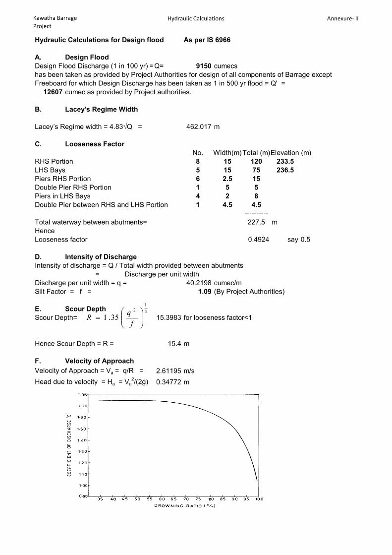
Hydraulic Calculations for Design flood As per IS 6966
A. Design FloodDesign Flood Discharge (1 in 100 yr) =Q= 9150 cumecshas been taken as provided by Project Authorities for design of all components of Barrage except Freeboard for which Design Discharge has been taken as 1 in 500 yr flood = Q' =
12607 cumec as provided by Project authorities.
B. Lacey's Regime Width
Lacey’s Regime width = 4.83√Q = 462.017 m
C. Looseness FactorNo. Width(m)Total (m)Sill Elevation (m)
RHS Portion 8 15 120 233.5LHS Bays 5 15 75 236.5Piers RHS Portion 6 2.5 15Double Pier RHS Portion 1 5 5Piers in LHS Bays 4 2 8Double Pier between RHS and LHS Portion 1 4.5 4.5
----------Total waterway between abutments= 227.5 mHenceLooseness factor 0.4924 say 0.5
D. Intensity of DischargeIntensity of discharge = Q / Total width provided between abutments
= Discharge per unit widthDischarge per unit width = q = 40.2198 cumec/mSilt Factor = f = 1.09 (By Project Authorities)
E. Scour DepthScour Depth= 15.3983 for looseness factor<1
Hence Scour Depth = R = 15.4 m
F. Velocity of ApproachVelocity of Approach = Va = q/R = 2.61195 m/sHead due to velocity = Ha = Va
2/(2g) = 0.34772 m
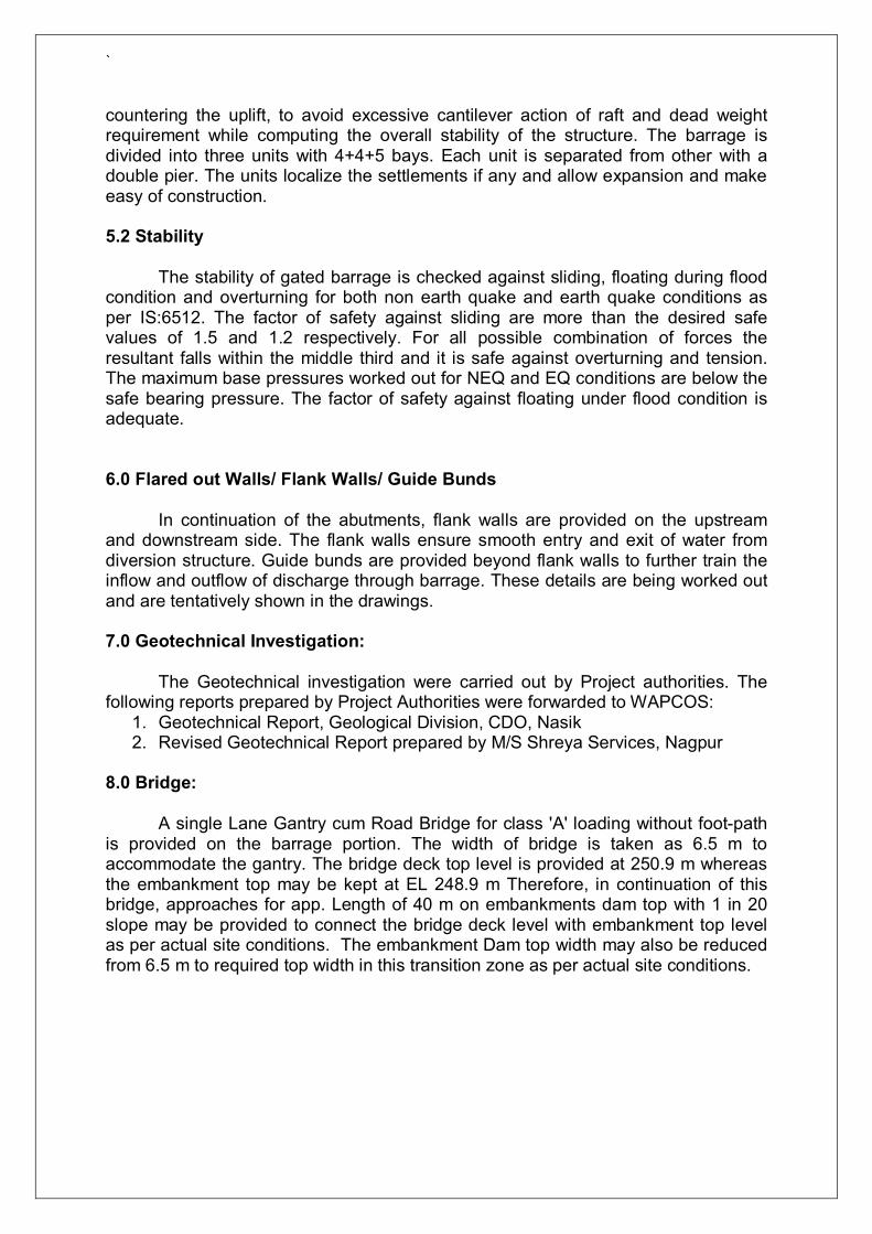
Mallikpur Curve
31
2
35.1
fqR

Kawatha Barrage Project
Hydraulic Calculations Annexure- II
G. Water way calculation with 8 bays at EL 233.5 (RHS portion) and 5 bays at 236.5 (LHS portion)for Design Discharge(1 in 100 yr flood) 9150 cumecsWith all gates fully opened
Water Level corresponding to design flood(Un-Retro.) = 245.63 mAfflux assumed = = 0.2691 mAffluxed Water Level = 245.90 mSill Level of the RHS Portion = = 233.5 m
Dischage Q1 from RHS PortionDrownded Weir Formula = C L ( (H +Ha)
3/2 - Ha3/2)
Drowning ratio = d/s HFL - crest level of spillwayu/s HFL - crest level of spillway
ThereforeDrowning Ratio = 0.9783 i.e. 0.9783Cd = 1.17373 (from Mallikpur Curves)L = 120H = 12.40
Discharge Q1 = = 6381.02 cumecs
Discaharge Q2 from LHS BaysSill Level of the LHS Bays = = 236.5 m
Drownded Weir Formula = C L ( (H +Ha)3/2 - Ha
3/2)Drowning ratio = d/s HFL - crest level of spillway
u/s HFL - crest level of spillway
ThereforeDrowning Ratio = 0.97137 i.e. 0.9714Cd = 1.22152 (from Mallikpur Curves)L = 75H = 9.40
Discharge=Q2 = 2768.98 cumecs
Hence Total Discharge = =Q1+Q2= 9150 cumecs
Hence Affluxed HFL for 1 in 100 yr discharge is calculated as 245.9 m

Kawatha Barrage Project
Hydraulic Calculations Annexure- II
H. Afflux Calculation for Discharge(1 in 500 yr flood) 12607 cumecsWith all gates fully opened
Water Level corresponding to design flood(Un-Retro.) = 246.63 mAfflux assumed = = 0.7472 mAffluxed Water Level = 247.38 mSill Level of the RHS Portion = = 233.5 m
Dischage Q1 from RHS PortionDrownded Weir Formula = C L ( (H +Ha)
3/2 - Ha3/2)
Drowning ratio = d/s HFL - crest level of spillwayu/s HFL - crest level of spillway
ThereforeDrowning Ratio = 0.94616 i.e. 0.9462Cd = 1.34737 (from Mallikpur Curves)L = 120H = 13.8772
Discharge=Q1 = 8641.27 cumecsDiscaharge Q2 from LHS BaysSill Level of the LHS Bays = = 236.5 m
Drownded Weir Formula = C L ( (H +Ha)3/2 - Ha
3/2)Drowning ratio = d/s HFL - crest level of spillway
u/s HFL - crest level of spillway
ThereforeDrowning Ratio = 0.93131 i.e. 0.9313Cd = 1.41372 (from Mallikpur Curves)L = 75H = 10.88
Discharge=Q2 = 3965.73 cumecs
Hence Total Discharge = =Q1+Q2= 12607 cumecs
Hence Affluxed HFL for 1 in 500 yr discharge is calculated as 247.38 m
J. Conclusions
Computed affluxed waterlevel for design discharge of 1 in 500 yr flood is 247.38 m.
Piers shall be taken 1.52 m above this affluxed water levelHence Pier Top = 247.38 + 1.52 = 248.90 m Bridge Top = 248.9 + 2 = 250.9 m
A slope of 1 in 20 shall be provided at the embankment top for length= 40 m on either side
Kawatha Barrage Project
Hydraulic Calculations Annexure- II
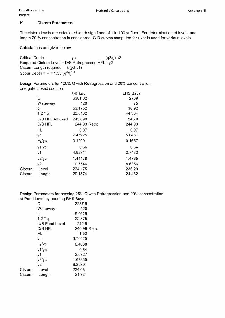
K. Cistern Parameters
The cistern levels are calculated for design flood of 1 in 100 yr flood. For determination of levels and length 20 % concentration is considered. G-D curves computed for river is used for various levels
Calculations are given below:
Critical Depth= yc = (q2/g)1/3Required Cistern Level = D/S Retrogressed HFL - y2Cistern Length required = 5(y2-y1)Scour Depth = R = 1.35 (q2/f)1/3
Design Parameters for 100% Q with Retrogression and 20% concentrationone gate closed codition
RHS Bays LHS BaysQ 6381.02 2769Waterway 120 75q 53.1752 36.921.2 * q 63.8102 44.304U/S HFL Affluxed 245.899 245.9D/S HFL 244.93 Retro 244.93HL 0.97 0.97yc 7.45925 5.8487HL/yc 0.12991 0.1657y1/yc 0.66 0.64y1 4.92311 3.7432y2/yc 1.44178 1.4765y2 10.7546 8.6356
Cistern Level 234.175 236.29Cistern Length 29.1574 24.462
Design Parameters for passing 25% Q with Retrogression and 20% concentrationat Pond Level by opening RHS Bays
Q 2287.5Waterway 120q 19.06251.2 * q 22.875U/S Pond Level 242.5D/S HFL 240.98 RetroHL 1.52yc 3.76425HL/yc 0.4038y1/yc 0.54y1 2.0327y2/yc 1.67335y2 6.29891
Cistern Level 234.681Cistern Length 21.331

Kawatha Barrage Project
Hydraulic Calculations Annexure- II
cistern Level shall also be checked for condition when all gates are opened by 1; 2; 3 m etc.at pond Level conditionAs per cl 4.3.1.1 of IS 6531 "Canal Head Regulator - Criteria and Design"Discharge through partly open gates = 2/3 C√(2g) (H1
3/2-H23/2)
g= Acc due to gravity = 9.81 m/s2
H1 = Head upto bottom level of gate openingH2 = Head upto top level of gate opening C = Constant whose value varies from 0.85 to 1.2 depending upon many factorTaking C = 1Pond Level = 242.5 mSill level of Centrl Bays = 233.5For opening = 1 mH1 = 9 mH2 = 8 mDischarge for one gate opening =12.9121 cumecsTotal Discharge = 103.297 cumecs all 8 RHS bays openD/s HFL for such case = 232 m top level of End Sill
Q 12.9121Waterway 15q 0.860811.2 * q 1.03297U/S Pond Level 242.5D/S HFL 232.00HL 10.50yc 0.47735Hl/yc 21.9964y1/yc 0.14y1 0.06683y2/yc 3.71029y2 1.77111
Cistern Level 230.229Cistern Length 8.52141For opening = 2 mH1 = 9 mH2 = 7 mDischarge for one gate opening =25.0404 cumecsTotal Discharge = 200.323 cumecs all 8 RHS bays openD/s HFL for such case = 233 m RetrogressedCistern parameter for such case
Q 25.0404Waterway 15q 1.669361.2 * q 2.00323U/S Pond Level 242.5D/S HFL 233.00HL 9.50yc 0.74233Hl/yc 12.7975y1/yc 0.18y1 0.13362y2/yc 3.24455y2 2.40854
Cistern Level 230.591Cistern Length 11.3746

Kawatha Barrage Project
Hydraulic Calculations Annexure- II
For opening = 3 mH1 = 9 mH2 = 6 mDischarge for one gate opening =36.3305 cumecsTotal Discharge = 290.644 cumecs all 8 RHS bays openD/s HFL for such case = 233.5 m Retrogressed
Cistern parameter for such caseQ 36.3305Waterway 15q 2.422031.2 * q 2.90644U/S Pond Level 242.5D/S HFL 233.50HL 9.00yc 0.95137Hl/yc 9.46y1/yc 0.21y1 0.19979y2/yc 2.98285y2 2.83781
Cistern Level 230.662Cistern Length 13.1901
For opening = 4 mH1 = 9 mH2 = 5 mDischarge for one gate opening =46.7149 cumecsTotal Discharge = 373.719 cumecs all 8 RHS bays openD/s HFL for such case = 234 m Retrogressed
Cistern parameter for such caseQ 46.7149Waterway 15q 3.114331.2 * q 3.73719U/S Pond Level 242.5D/S HFL 234.00HL 8.50yc 1.12497Hl/yc 7.55577y1/yc 0.23y1 0.25874y2/yc 2.83608y2 3.1905
Cistern Level 230.81Cistern Length 14.6588Hence Provide Centrl Bays Stilling basin at cistern top elevation 230 m and length
30 m along with Basin blocks

Kawatha Barrage Project
Hydraulic Calculations Annexure- II
Similarily for LHS BaysDischarge through partly open gates = 2/3 C√(2g) (H1
3/2-H23/2)
g= Acc due to gravity = 9.81 m/s2
H1 = Head upto bottom level of gate openingH2 = Head upto top level of gate opening C = Constant whose value varies from 0.85 to 1.2 depending upon many factorTaking C = 1Pond Level = 242.5 mSill level of LHS Bays = 236.5For opening = 1 mH1 = 6 mH2 = 5 mDischarge for one gate opening =10.3844 cumecsTotal Discharge = 51.922 cumecs all 5 LHS bays openD/s HFL for such case = 234.5 m top level of End SillCistern parameter for such case
Q 10.3844Waterway 15q 0.692291.2 * q 0.83075U/S Pond Level 242.5D/S HFL 234.50HL 8.00yc 0.41282Hl/yc 19.3789y1/yc 0.15y1 0.06192y2/yc 3.57725y2 1.47676
Cistern Level 233.023Cistern Length 7.07421
For opening = 2 mH1 = 6 mH2 = 4 mDischarge for one gate opening =19.7758 cumecsTotal Discharge = 98.8791 cumecs all 5 LHS bays openD/s HFL for such case = 234.5 m top level of End SillCistern parameter for such case
Q 19.7758Waterway 15q 1.318391.2 * q 1.58207U/S Pond Level 242.5D/S HFL 234.50HL 8.00yc 0.63425Hl/yc 12.6133y1/yc 0.18y1 0.11417y2/yc 3.24455y2 2.05786
Cistern Level 232.442Cistern Length 9.71848

Kawatha Barrage Project
Hydraulic Calculations Annexure- II
For opening = 3 mH1 = 6 mH2 = 3 mDischarge for one gate opening =28.0555 cumecsTotal Discharge = 140.277 cumecs all 5 LHS bays openD/s HFL for such case = 234.5 m top level of End Sill
Cistern parameter for such caseQ 28.0555Waterway 15q 1.870371.2 * q 2.24444U/S Pond Level 242.5D/S HFL 234.50HL 8.00yc 0.80079Hl/yc 9.99018y1/yc 0.2y1 0.16016y2/yc 3.06386y2 2.45349
Cistern Level 232.047Cistern Length 11.4667
Hence Provide LHS Bays Stilling basin at cistern top elevation 232 m and length25 m along with Basin blocks
L. Scour Depth for Various Condition
Silt Factor = f = 1.09Scour Depth = R = 1.35 (q2/f)1/3U/S scour level is at Scour depth R whereas D/S scour Level is at 1.25 R
Q Q1Waterw
ay 1.2 x q R 1.25 R U/S WL D/S WL
U/S Scour Level
D/S Scour Level
6382.00 142.25 53.84 18.70 23.37 245.63 244.93 226.93 221.562769.00 85.25 32.48 13.35 16.69 245.63 244.93 232.28 228.24
These levels shall be further checked for safe exit gradients
9150
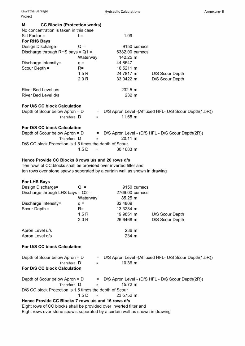
Kawatha Barrage Project
Hydraulic Calculations Annexure- II
M. CC Blocks (Protection works)No concentration is taken in this caseSilt Factor = f = 1.09For RHS BaysDesign Discharge= Q = 9150 cumecsDischarge through RHS bays = Q1 = 6382.00 cumecs
Waterway 142.25 mDischarge Intensity= q = 44.8647Scour Depth = R= 16.5211 m
1.5 R 24.7817 m U/S Scour Depth 2.0 R 33.0422 m D/S Scour Depth
River Bed Level u/s 232.5 mRiver Bed Level d/s 232 m
For U/S CC block CalculationDepth of Scour below Apron = D = U/S Apron Level -(Affluxed HFL- U/S Scour Depth(1.5R))
Therefore D = 11.65 m
For D/S CC block CalculationDepth of Scour below Apron = D = D/S Apron Level - (D/S HFL - D/S Scour Depth(2R))
Therefore D = 20.11 mD/S CC block Protection is 1.5 times the depth of Scour
1.5 D = 30.1683 m
Hence Provide CC Blocks 8 rows u/s and 20 rows d/s Ten rows of CC blocks shall be provided over inverted filter and ten rows over stone spawls seperated by a curtain wall as shown in drawing
For LHS BaysDesign Discharge= Q = 9150 cumecsDischarge through LHS bays = Q2 = 2769.00 cumecs
Waterway 85.25 mDischarge Intensity= q = 32.4809Scour Depth = R= 13.3234 m
1.5 R 19.9851 m U/S Scour Depth2.0 R 26.6468 m D/S Scour Depth
Apron Level u/s 236 mApron Level d/s 234 m
For U/S CC block Calculation
Depth of Scour below Apron = D = U/S Apron Level -(Affluxed HFL- U/S Scour Depth(1.5R))Therefore D = 10.36 m
For D/S CC block Calculation
Depth of Scour below Apron = D = D/S Apron Level - (D/S HFL - D/S Scour Depth(2R))Therefore D = 15.72 m
D/S CC block Protection is 1.5 times the depth of Scour 1.5 D = 23.5752 m
Hence Provide CC Blocks 7 rows u/s and 16 rows d/s Eight rows of CC blocks shall be provided over inverted filter and Eight rows over stone spawls seperated by a curtain wall as shown in drawing

Kawatha Barrage Project
Hydraulic Calculations Annexure- II
N. Launching apron
RHS Bays Upstream -
Depth of scour below the floor level on U/S side = L = 11.65 M (1.5R with u/s WL)Consider slope to be 2H : 1V Then launched length = √(5)* L = 26.054 MIf 1 m thickness of launching apron is adoped Qty of stones=26.054 M3For 1.5 m thick Launching apron, length of unlaunched apron=17.369 m
RHS Bays Downstream -
Depth of scour below the floor level on D/S side = L = 20.112 M (2R with d/s WL)Consider slope to be 2H : 1V Then launched length = √(5)* L = 44.972 MIf 1 m thickness of launching apron is adoped Qty of stones=44.972 M3For 1.5 m thick Launching apron, length of unlaunched apron=29.982 m
Hence Provide 1500 thick launching apron for length 18 m u/s and 30 m d/s
LHS Bays Upstream -
Depth of scour below the floor level on U/S side = L = 10.36 M (1.5R with u/s WL)Consider slope to be 2H : 1V Then launched length = √(5)* L = 23.155 MIf 1 m thickness of launching apron is adoped Qty of stones=23.155 M3For 1.5 m thick Launching apron, length of unlaunched apron=15.436 m say 16 m
LHS Bays Downstream -
Depth of scour below the floor level on D/S side = L = 15.72 M (2R with d/s WL)Consider slope to be 2H : 1V Then launched length = √(5)* L = 35.144 MIf 1 m thickness of launching apron is adoped Qty of stones=35.144 M3For 1.5 m thick Launching apron, length of unlaunched apron=23.429 m say 24 m
Hence Provide 1500 thick launching apron for length 16 m u/s and 24 m d/s

Kawatha Barrage Project
Hydraulic Calculations Annexure- II
O. Flared Out Walls
Flared out walls are to be provided on upstream and downstream of Barrage between LHSbays and RHS bays and also between embankment and adjoining LHS / RHS Abutment
Flared out Walls between RHS bays and LHS bays
Design DataU/S D/S
1 Apron Level LHS bay = 232.5 m 232 m2 Apron Level RHS bay = 236 m 234 m3 Level Difference = 3.5 m 2 m4 Silt factor = 1.09 (See Hydraulic Design memo)
Design Parameters1 Top thickness of Flareed out wall
Minimum Top thickness of flared out /flank wall is 600 mm C. 5.7.1.1 of IS 11130 "Criteria for Structural design of Barrages and weirs"However 1500 mm is adopted as top thickness.
2 Length of Flank WallThe length of the flankwall as per cl 5.7 of IS 11130 UpstreamAt guide bund (upstream end of upstream flaredout wall) slope provided to the sides:
2 H : 1 VFor 3.5 m level difference Horizonal Length= 7 m
Vertical Length = 3.5 mSloping length L1= 7.82624 m
Length of upstream wall 2 to 2.5 times L1Length of upstream wall 15.6525 to 19.5656 m
However Provide 16 m length of flared out wall as shown in drawing
DownstreamAt guide bund (downstream end of downstream flank wall) slope provided to the sides:
2 H : 1 VFor 2 m level difference Horizonal Length= 4 m
Vertical Length = 2 mSloping length L2= 4.47214 m
Length of upstream wall 2.5 to 3 times L2Length of upstream wall 11.1803 to 13.42 m
However Provide 12 m length of flared out wall as shown in drawing
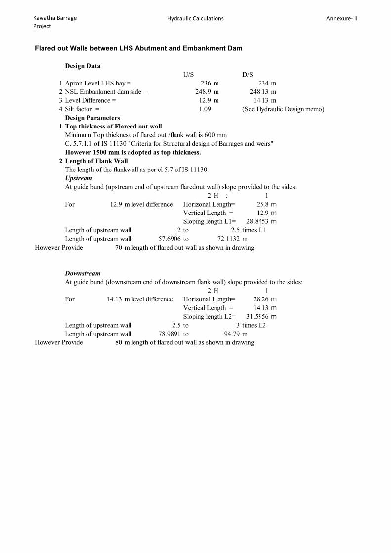
Kawatha Barrage Project
Hydraulic Calculations Annexure- II
Flared out Walls between LHS Abutment and Embankment Dam
Design DataU/S D/S
1 Apron Level LHS bay = 236 m 234 m2 NSL Embankment dam side = 248.9 m 248.13 m3 Level Difference = 12.9 m 14.13 m4 Silt factor = 1.09 (See Hydraulic Design memo)
Design Parameters1 Top thickness of Flareed out wall
Minimum Top thickness of flared out /flank wall is 600 mm C. 5.7.1.1 of IS 11130 "Criteria for Structural design of Barrages and weirs"However 1500 mm is adopted as top thickness.
2 Length of Flank WallThe length of the flankwall as per cl 5.7 of IS 11130 UpstreamAt guide bund (upstream end of upstream flaredout wall) slope provided to the sides:
2 H : 1For 12.9 m level difference Horizonal Length= 25.8 m
Vertical Length = 12.9 mSloping length L1= 28.8453 m
Length of upstream wall 2 to 2.5 times L1Length of upstream wall 57.6906 to 72.1132 m
However Provide 70 m length of flared out wall as shown in drawing
DownstreamAt guide bund (downstream end of downstream flank wall) slope provided to the sides:
2 H 1For 14.13 m level difference Horizonal Length= 28.26 m
Vertical Length = 14.13 mSloping length L2= 31.5956 m
Length of upstream wall 2.5 to 3 times L2Length of upstream wall 78.9891 to 94.79 m
However Provide 80 m length of flared out wall as shown in drawing
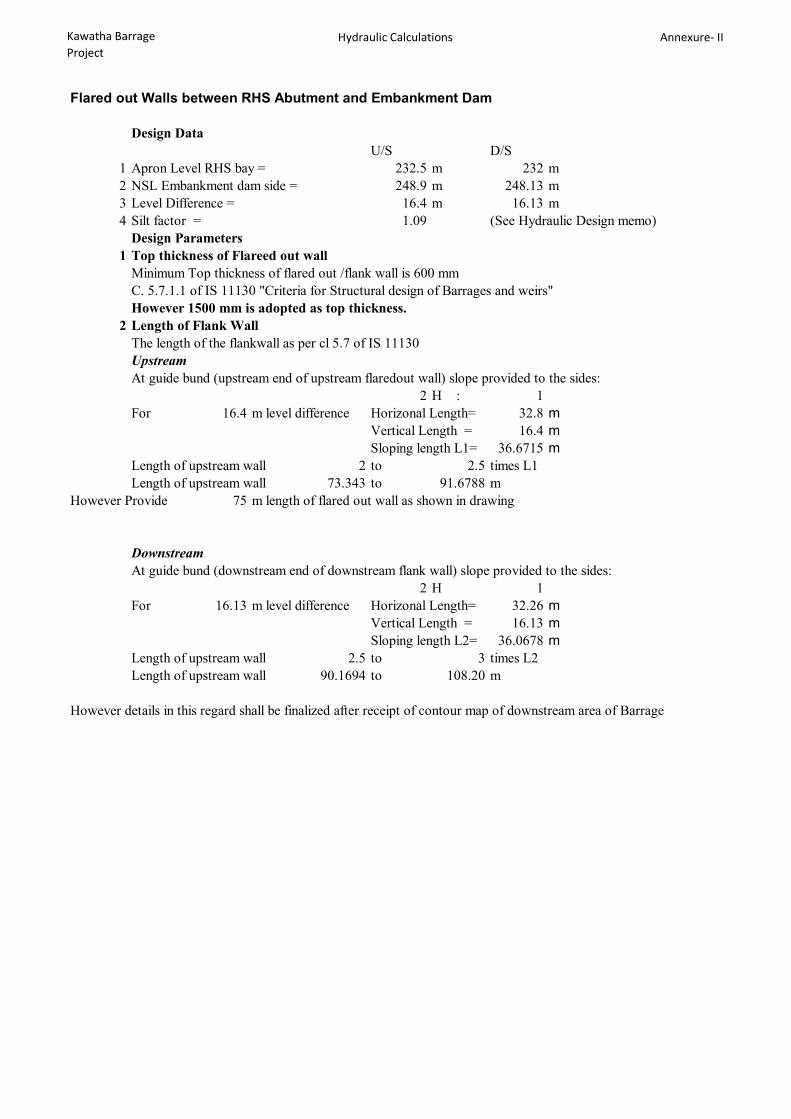
Kawatha Barrage Project
Hydraulic Calculations Annexure- II
Flared out Walls between RHS Abutment and Embankment Dam
Design DataU/S D/S
1 Apron Level RHS bay = 232.5 m 232 m2 NSL Embankment dam side = 248.9 m 248.13 m3 Level Difference = 16.4 m 16.13 m4 Silt factor = 1.09 (See Hydraulic Design memo)
Design Parameters1 Top thickness of Flareed out wall
Minimum Top thickness of flared out /flank wall is 600 mm C. 5.7.1.1 of IS 11130 "Criteria for Structural design of Barrages and weirs"However 1500 mm is adopted as top thickness.
2 Length of Flank WallThe length of the flankwall as per cl 5.7 of IS 11130 UpstreamAt guide bund (upstream end of upstream flaredout wall) slope provided to the sides:
2 H : 1For 16.4 m level difference Horizonal Length= 32.8 m
Vertical Length = 16.4 mSloping length L1= 36.6715 m
Length of upstream wall 2 to 2.5 times L1Length of upstream wall 73.343 to 91.6788 m
However Provide 75 m length of flared out wall as shown in drawing
DownstreamAt guide bund (downstream end of downstream flank wall) slope provided to the sides:
2 H 1For 16.13 m level difference Horizonal Length= 32.26 m
Vertical Length = 16.13 mSloping length L2= 36.0678 m
Length of upstream wall 2.5 to 3 times L2Length of upstream wall 90.1694 to 108.20 m
However details in this regard shall be finalized after receipt of contour map of downstream area of Barrage

Kawatha Barrage Project
Exit gradient Calculation Annexure-II
Pond Level 242.5
CrestH = 10.5
U/S RiverBed 232.5
232 D/S River Bed
Stilling Basin 230.0
U/S CutOff
d = 10.5225 RHS Bay
D/S Cutoff
221.5
b= 64
Exit Gradient Calculations
Maximum water head acting for exit gradient = H = 10.5Depth of downstream cutoff = d = = 10.5Total Floor Length = b = 64
α = b/d = 6.095238
λ = 3.588362 Where
Exit Gradient = GE = 0.168036 Where GE =
or I in 6.0 Hence Safe
1dH
211 2

Kawatha Barrage Project
Exit gradient Calculation Annexure-II
Pond Level 242.5
CrestH = 8.5
U/S RiverBed 236
234 D/S River Bed
Stilling Basin 232.0
U/S CutOff
d = 7.8229 LHS Bay
D/S Cutoff
226.2
b= 62
Exit Gradient Calculations
Maximum water head acting for exit gradient = H = 8.5Depth of downstream cutoff = d = = 7.8Total Floor Length = b = 62
α = b/d = 7.948718
λ = 4.505687 Where
Exit Gradient = GE = 0.163416 Where GE =
or I in 6.1 Hence Safe
1dH
211 2
Related Documents