The European Union’s Food Security Programme for Yemen Technical Assistance to the Tihama Development Authority DESIGN MANUAL VOLUME 1 TECHNICAL DESIGN CRITERIA December 2008

Welcome message from author
This document is posted to help you gain knowledge. Please leave a comment to let me know what you think about it! Share it to your friends and learn new things together.
Transcript
The European Union’s Food Security Programme for Yemen
Technical Assistance to the Tihama Development Authority
DESIGN MANUAL
VOLUME 1
TECHNICAL DESIGN CRITERIA
December 2008

The European Union’s Food Security Programme for Yemen Technical Assistance to the Tihama Development Authority
DESIGN MANUAL
VOLUME 1: TECHNICAL DESIGN CRITERIA
December 2008
TABLE OF CONTENTS Page
List of Abbreviations Introduction 1. Design Considerations 1 1.1 Optimizing Costs & Benefits 1
1.2 Freeboard 1 1.3 Scour 1 1.4 Wall Stability 2 1.5 Uplift 2
1.6 Seepage & Piping 2 1.7 Energy Dissipation 3 1.8 Bed Bar Design 3 1.9 Material Preferences – Structures 3 1.10 Material Preferences – Erosion Protection 4 2. Hydraulic Design 5 2.1 Weirs 5
2.2 Scour Sluices 6 2.3 Head Regulators 6 2.4 Free Wadi Intakes 7 2.5 Channel Flow 7
2.6 Pipe Flow 8 3. Design for Seepage, Uplift, & Scour 9 3.1 Design for Seepage 9 3.2 Thickness of Concrete to Resist Uplift 10 3.3 Scour Protection 10 4. Structural Design 12 4.1 Reinforced Concrete Design 12 4.2 Reinforcement Standards 12 4.3 Joints in Concrete 12 4.4 Bridge Loading Standards 13 4.5 Masonry Walls 14 5. Geotechnical Design 15 5.1 Retaining Wall Design 15 5.2 Bearing Capacity 17

FIGURES
Figure 1: Flow over Weirs 6
TABLES
Table 1: Pipe Roughness Coefficients 8 Table 2: K Factor for Pipe Fittings 8 Table 3: Coefficients for Weighted Creep & Exit Gradient 10 Table 4: Silt Factor Coefficients 11 Table 5: Severity Factor Coefficients 11 Table 6: Concrete Classes 12 Table 7: Partial safety Factors for Bridge Loading 13 Table 8: Types of Masonry 14
ANNEXES
Annex 1: Drafting Standards Annex 2: Contents of Design CD-ROM

List of Abbreviations “The Project” Technical Assistance to the Tihama Development Authority at Yemen
EuropeAid/122248/C/SV/YE GOY Government of (the Arab Republic of) Yemen TA Technical Assistance (currently contracted to Euroconsult Mott MacDonald) TDA Tihama Development Authority YR Yemeni Rial (currently approx. 1 Euro = 200 YR)

Introduction This Manual has been prepared by the Project TA team, and covers the essential technical procedures required for the development of spate irrigation civil works infrastructure. The Manual has three Volumes: Volume 1: Technical Design Criteria (this Volume) The contents of Volume 1 are based on the design criteria developed and used on the World Bank-funded IIP Wadi Tuban and Wadi Zabid Project, 2001 – 2005. Volume 2: Guidelines for Wadi Diversion and Protection Works Volume 2 is the report of the River Training Specialist. Volume 3: Design Presentations Volume 3 contains copies of design presentations given separately by the River Training Specialist and the Irrigation Engineer. In addition to this Manual, the TA team has also provided TDA with a CD-ROM containing many additional technical references, which are listed in Annex 2 to this Volume.

1
1. DESIGN CONSIDERATIONS In order to create cost-effective designs it is necessary to carefully scrutinise conventional design procedures and assumptions. The main points to consider are described in the following paragraphs. 1.1 OPTIMIZING COSTS & BENEFITS Spate irrigation is inherently risky and it is appropriate that engineering design accepts a higher level of risk in order to reduce costs to a level more appropriate to the poor economic returns. The challenge for the designer is to avoid catastrophic damage. The larger the investment, then the greater the need to ensure its security against failure. The greatest threat to the structures is a massive flood. There is a possibility of a massive flood arriving at any time, but the probability increases with the time elapsed. The peak flood flow is likely to be of short duration and, where the mode of failure is progressive, this reduces the risk of major damage. The risk of flood damage is greatest for structures within or adjacent to the wadis. Canal structures are subject to a much lower level of risk. Overtopping and submergence of structures is unlikely to cause serious damage, particularly if only for a short period of time. Abrasion damage is a further potential cause of damage. Apart from damage to the wires of gabions in the wadi bed, abrasion damage is unlikely to be very fast and cause sudden failure. Gabion materials have a life expectancy of 20 to 30 years, depending on exposure conditions, before major repair or replacement is needed. It is therefore inappropriate to design gabion works for flood events rarer than about 1 in 20 years. Where widescale failure of gabions could result in catastrophic damage, they should not be used. Structures in masonry or concrete may have a nominal design life of 30 years, but can be expected to last longer if timely repairs and maintenance are carried out. Overall, normal design processes include several factors of safety which, when combined, result in conservative designs. Costs and benefits need to be considered in the context of the risk of adverse circumstances occurring at the same time and resulting in a failure. In general, this means that wadi structures may be designed to be less conservative than designs for perennial irrigation schemes. 1.2 FREEBOARD Normal irrigation design includes allowance for freeboard above the design water level. For spate irrigation there is much less certainty about the magnitude of flows. Large flows will also tend to scour and increase channel capacity. In the extreme condition, canals will overtop their banks, which may cause breaching. However, these can be repaired. Therefore no additional freeboard allowance is necessary for spate irrigation systems. 1.3 SCOUR Potential scour usually calculated using the Lacey formula, which is simple but based on conditions in the Indian subcontinent. Its applicability to rivers with gravel beds and very high sediment loads is less certain but is believed to be conservative. Sediment transport regime studies have indicated high sediment loads increase the threshold at which scour occurs and it is logical that the same principle applies to scour. For example, if a scour hole develops in the bed of a wadi transporting material of different sizes, the larger material will tend to fall into the hole and protect against further scour. In some locations the scour protection tends to be provided to maintain appearance by preventing erosion of a channel bed or banks. To reduce costs, such protection can be reduced or eliminated provided that any scour will not endanger the integrity of structures or embankments. In other locations it is more cost-effective to deepen structure foundations or cut-offs instead of providing scour protection. Scour holes tend to be infilled when the floods recede. Overall, design for scour protection falls into three groups:
2
1. Full protection is provided where there is risk of loss of life, ie at village protection works. 2. Reduced (compared with theoretical requirements) protection is provided at structures within
wadis. 3. Nominal protection is provided at canal and in-field structures.
1.4 WALL STABILITY In general, designs make extensive use of mass masonry walls. In general, the walls are mounted on base slabs for the whole structure, which eliminates the risk of wall foundation failure. Over-turning of the wall about the toe through compressive failure of the wall material, is a potential mode of failure but would only occur if the resultant load is very high and passes through or close to the toe. Usually, the main destabilising force on a wall is water behind the wall. In most design situations for the project, this loading is unlikely to become a threat. Where groundwater levels are low then the tendency will be for any water moving behind walls to percolate downwards and only exert limited lateral force. An exception to this condition may be the drop wall of a drop structure where the source of water is above the wall. Wall stability will also be improved by the 3-dimensional nature of many structures where walls join to other walls, thereby improving overall stability. The drop wall of a drop structure is effectively a beam spanning between two side walls and failure is unlikely to be from overturning. For structures in the main wadis a further issue is the time required to develop a destabilising water pressure during a flood event. The time required for sufficient water to percolate behind a wall to create a hydrostatic load is likely to be longer than the duration of high water levels. Various calculations have demonstrated that a mass wall with a 3V : 1H back slope on an overall base slab wider than the wall itself is stable for conditions not including a substantial hydrostatic loading. 1.5 UPLIFT Actual groundwater level is at wadi bed level for works in the upstream parts of the project areas and well below ground level elsewhere. Therefore seepage water below structures will tend to percolate downwards and is considered unlikely to cause flotation of structures through uplift pressures. In addition, the nature of the floods is such that exposure to severe conditions is only likely to be for a short period of time, which is insufficient for destabilising conditions to develop. Where uplift pressures may occur, drainage is the preferred solution. For many structures, uplift can usually be resisted by the dead weight of the side walls, but where structures are wide then upward bending of the base slab needs to be checked. 1.6 SEEPAGE & PIPING Seepage beneath or around structures may occur where there is a difference in water levels between upstream and downstream. Seepage may occur irrespective of groundwater conditions if an easy seepage path exists. Cutoffs installed to reduce seepage increase the potential uplift pressures. However, as noted above, the ground is rarely fully saturated and water will move downwards instead of exerting a large uplift force on the structure. The main reason for cutoffs is to ensure that scour does not expose the underside of the structure base. Seepage represents a loss of water but is only damaging if it causes piping. Piping is caused when seepage washes out soil from beneath or around the structure. Traditionally, prevention of piping was caused by carefully designed and constructed graded filters which enabled water to be drained without washing out the soil. However, the availability of geotextiles substantially reduces the design and construction effort and facilitates the emergence of any seepage without threat of damage. Piping failures may occur at the structure - wall interface. Wing walls may be provided to lengthen any seepage paths behind structure side walls. Care must be taken during construction to ensure that
3
walls are solid and do not contain voids, that backfill does not contain very permeable material, and that there is no gap between the structure and adjacent filters. A specific problem for spate irrigation design is where it is proposed to use an earth bund within a structure. If an earth bund is placed between two walls there is a real risk of a seepage and piping failure occurring between the earth and the wall. The solution to this is to place the earth bund upstream of the structure so that there is a soil-to-soil contact. 1.7 ENERGY DISSIPATION Conventional design of hydraulic structures gives considerable emphasis to achieving full energy dissipation within the confines of the structure. This can add substantially to the cost of the structures. In order to achieve cost-effective structures for spate irrigation, it is often appropriate to compromise on the extent of energy dissipation provided by one or more of the following:
1. Examination of overall heads and velocities to ensure that there is energy to be dissipated. In many situations there is a need to keep velocities relatively high in order to transport sediment.
2. Use of a dominant (50% to 80% of maximum) flow for the sizing of stilling basins. 3. Provision of channel protection downstream of a structure to prevent damage from turbulent
flows emerging from structures. 4. Acceptance of scour downstream of structures in the knowledge that the high sediment loads
tend to infill scour holes as the flow recedes. 5. Provide cutoffs or build foundations below the expected scour depths.
1.8 BED BAR DESIGN A bed bar is effectively a buried wall with its top at, or slightly above, wadi bed level and is intended to prevent the lowering of the wadi channel adjacent to the canal the intake. The likely mechanisms of failure of bed bars would include abrasion, impact and the development of a scour hole on the downstream side, resulting in overturning. Retrogression of the downstream bed would turn the bed bar into a drop structure which would eventually cause failure. However, this is unlikely to occur unless there is substantial material extraction downstream of the structure. The high sediment loads during floods are more likely to cause bed aggradation. The design of bed bars is best based on traditional practice. Studies of such works in the Tihama indicate that gabion works inside the main wadi channel are vulnerable to severe damage during large floods. Therefore the preferred material for bed bars is mass concrete, which can be cast into excavated trenches. 1.9 MATERIAL PREFERENCES - STRUCTURES There are four main alternatives for construction materials for structures.
1. Masonry 2. Mass concrete 3. Reinforced concrete 4. Gabions
Reinforced concrete requires close attention to construction quality to create a durable product. It is therefore not preferred except for members such a breast walls and bridge slabs. Gabions are suitable in some locations. They are most suitable for remote sites where stone is available, because only the empty baskets have to be transported. They can be cost effective at other locations if stone plus gabion baskets of suitable quality are available and are not subjected to abrasive conditions. There is uncertainty about the quality of gabion materials available in Yemen and the overall design strategy should be not to use gabions unless the farmers indicate a strong preference.
4
Mass concrete and masonry are both assumed to have the same basic structural properties, so the choice between them depends on materials availability and ease of construction. Concrete in walls requires formwork which, if poorly constructed, will result in a poor quality finish. In general, the preferred form of construction for structures is a mass concrete base slab with mass masonry walls. Cutoffs are normally mass concrete cast into excavated trenches in order to form a good seal between the concrete and the ground. Blinding concrete is not normally required under mass concrete foundations unless there is a need to form a firm working base. The cost of thick mass concrete slabs can be reduced by using “plum” concrete, where up to 30% of the concrete is replaced by rocks typically 300mm diameter and embedded in the pour. Where technically feasible, designs that are easy to construct are preferred. This will make it easier for WUAs to replicate the designs in the future, should they wish to build additional similar structures. Such structures also tend to be easy to repair. 1.10 MATERIAL PREFERENCES – EROSION PROTECTION A range of materials can be used for erosion protection:
1. Gabion mattresses 2. Tipped rock 3. Uncemented stone pitching 4. Cemented stone pitching 5. Pitching with other materials
Gabion mattresses are a preferred material for major structures. Stone pitching is preferred for minor structures, which may be built by WUAs, to reduce potential procurement problems. Whether the pitching is cemented is usually determined by the farmers. Uncemented pitching over a geotextile is usually technically acceptable but farmers tend to prefer cemented pitching to reduce the possibility of the stones being removed. This risk also applies to tipped rock, unless the rock is large and therefore unsuitable for manual placing. Bank protection using unconventional materials such as old tyres, bricks or concrete blocks may also be considered. However, in most situations these materials are unlikely to be acceptable due to concerns about durability or the unproven approach.
5
3. HYDRAULIC DESIGN 3.1 WEIRS The standard weir equation is used to determine the head over the weir crest: for broad crested weir: Q = C (B – 0.1nh) H
3/2
and for oblique weir: Q=KCB H
3/2
Where Q is the discharge in m
3/s,
C is the discharge coefficient, taken as: C = 0.054 (L/h)² - 0.38 (L/h) + 2.05 L is the length of the crest, taken at about 1m B is the breadth of the weir across the wadi in m H is the total head over the weir, where H = h + (v
2/2g) in m
h is the head over the weir in m n is the number of side constrictions K is oblique factor depending on the angle α of the weir to the direction of flow:
Α 15 30 45 60 90
K 0.86 0.91 0.94 0.96 1
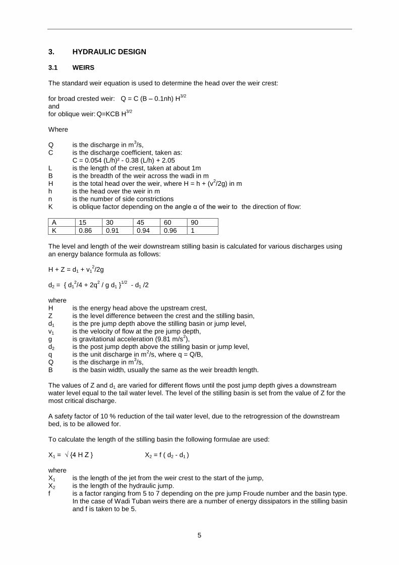
The level and length of the weir downstream stilling basin is calculated for various discharges using an energy balance formula as follows: H + Z = d1 + v1
2/2g
d2 = { d1
2/4 + 2q
2 / g d1 }
1/2 - d1 /2
where H is the energy head above the upstream crest, Z is the level difference between the crest and the stilling basin, d1 is the pre jump depth above the stilling basin or jump level, v1 is the velocity of flow at the pre jump depth, g is gravitational acceleration (9.81 m/s
2),
d2 is the post jump depth above the stilling basin or jump level, q is the unit discharge in m
2/s, where q = Q/B,
Q is the discharge in m3/s,
B is the basin width, usually the same as the weir breadth length. The values of Z and d1 are varied for different flows until the post jump depth gives a downstream water level equal to the tail water level. The level of the stilling basin is set from the value of Z for the most critical discharge. A safety factor of 10 % reduction of the tail water level, due to the retrogression of the downstream bed, is to be allowed for. To calculate the length of the stilling basin the following formulae are used: X1 = √ {4 H Z } X2 = f ( d2 - d1 ) where X1 is the length of the jet from the weir crest to the start of the jump, X2 is the length of the hydraulic jump. f is a factor ranging from 5 to 7 depending on the pre jump Froude number and the basin type.
In the case of Wadi Tuban weirs there are a number of energy dissipators in the stilling basin and f is taken to be 5.
6
Figure 1: FLOW OVER WEIRS
Tail Water Level
H
Crest Level
d2
Z Bed Level
d1 Jump Level Basin Level
X1 X2
3.2 SCOUR SLUICES Flow through the scour sluice is calculated using the following equations: 1) the weir equation, when the gates are open and the flow depth is below gate: Q = 95% x C1 bH
3/2
2) the orifice equation when the gate is partially closed: Q = C2 b w (2gH)
1/2
Where: C1 is the weir coefficient taken as 1.5, with a 95% reduction due to side constrictions. b is the width of the sluice opening H is the energy head upstream of the sluice
C2 is the coefficient of discharge for a radial gate, which approximates to 0.55. b is the width of the opening w is the height of the opening H is (y1 – y2) y1 is the upstream head, where y1 >(1.5 x w) y2 is the downstream head for drowned flow or δw for free flow δ is a factor between 0.62 to 0.64 3.3 HEAD REGULATORS For determining the discharge through the head regulator the same formulae as for the scour sluice are used. Allowances are made for the loss in crest width due to the effect of the piers, using: Be = B - 0.1 n H Where Be is the effective width of the weir L is the sum of the actual bay widths n is the number of piers H is the head over the weir

7
3.4 FREE WADI INTAKES The flow equation used for the bed bar is the adapted weir equation allowing for high approach velocity and downstream drowning: Q = FC (B – 0.1n h) {h + (v² /2g)}
3/2
Where: C = 0.054 (L/h)² - 0.38 (L/h) +2.05 B is the width of the bed bar across the channel L is the crest length of the bed bar n is the number of constrictions h is the upstream head over the weir crest v is the velocity of flow upstream F is a drowning reduction factor where: for C < 1.7 and M< 0.8, F = 1 for C < 1.7 and M> 0.8, F = 3.8 – 3.34M for C > 1.7 , F = -0.82M² + 0.11M +0.96 M is the modular ratio = hd/ h hd is the downstream head over the weir crest The flow equation for the spill weir is the same as for the bed bar but an oblique factor K may be applied depending on the geometry, see Section A1. The level of the spill weir is set at the level necessary to provide d0 the upstream depth to give the design discharge into the intake under flume flow. The flow equation used for the free wadi intake is: Q = C (b d3) √(2gH) where C = 0.82 for square edged intake = 0.90 for rounded edge intake b is the bay width d3 is the tail water depth H = d0 - d3 + (v0² /2g) d0 is the upstream water depth v0² is the upstream velocity To limit the flow entering the free intake under high flood a breast wall is set at a height d0 above the intake invert. When the upstream depth exceeds d0 the orifice equation is applied: Q = C2 b w (2gH)
1/2
3.5 CHANNEL FLOW The velocity and depth of flow for a particular discharge is most simply established through Manning’s equation: Q = (1/n) A R
2/3 s
1/2
where: Q is the discharge (m
3/s)
n is the roughness of the wadi bed A is the cross-sectional area of flow R is the hydraulic radius A/P P is the wetted perimeter s is the slope of the energy line, which approximates to the slope of the wadi bed.
8
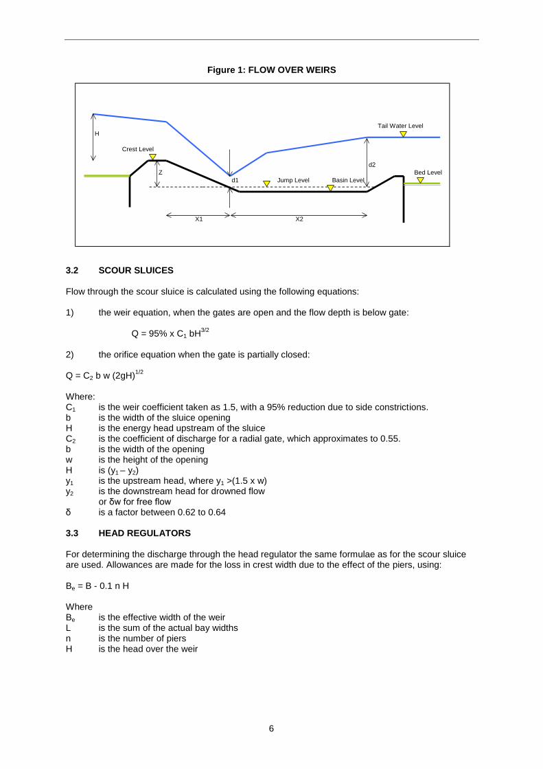
For high flood discharges the roughness of the wadi is taken as n = 0.035. This gives a realistic estimate of the observed flow depths and velocities. Due to the steepness of the wadi, a value of n less than 0.035 would give a Froude number greater than unity. This would result in an oscillating water surface making it difficult to predict the depth of flow. 3.6 PIPE FLOW The Hazen Williams equation is used to estimate pipe flow: V = (4.57 x 10
-3) C d
0.83 i
0.54
where: V is the velocity of flow in the pipe (m/s) C is the roughness for the pipe material, given in Table 1 d is the diameter of the pipe (mm) i is the hydraulic gradient = Δh / L Δh is the head difference across the pipe (m) L is the length of the pipe (m) The discharge through the pipe can then be calculated by: Q = V A where: Q is the discharge (m
3/s)
A is the cross-sectional area of the pipe (m2).
Entrance and exit losses are calculated from: H = k (V
2 / 2g), where the values of k are given in Table 2
Table 1: PIPE ROUGHNESS COEFFICIENTS
Pipe material Roughness C
Welded steel < 300mm dia Welded steel > 300mm dia Concrete PVC
120 130 140 to 150 150
Table 2: K FACTOR FOR PIPE FITTINGS
Fitting k
Sharp entrance Rounded entrance 45° bend 90° bend Sharp exit
0.50 0.25 0.40 1.00 1.00

9
4. DESIGN FOR SEEPAGE, UPLIFT, & SCOUR 4.1 DESIGN FOR SEEPAGE Lane’s weighted creep theory is used to determine the length of the structure and the depth of cut offs. The creep length should be greater than the maximum head difference x the creep coefficient: L c > C H where L c = L v + (1/3) x L h C is Lane’s creep coefficient (see Table A1), here taken as 4 for fine gravel H is the maximum head difference across the structure in metres L v is the sum of the vertical lengths in metres L h is the sum of the horizontal lengths in metres. Exit gradient is determined by the proportion of head remaining at the toe of the downstream cut off. G e = H e / D c where G e is the exit gradient, which must be less than 1/5 for fine gravel H e = (1- ( L p / L c ) ) H L p is the partial creep length to the toe of the downstream cut off in metres L c is the total creep length in metres D c is the downstream cut off depth from the underside of the scour protection layer in metres. Uplift pressures at various points under the structure are calculated from the residual head remaining to be dissipated at that point. This is checked for two cases: (a) under a no flow condition where the head difference is the difference between the weir crest
level and the downstream bed level (less the thickness of the scour protection). (b) under a full discharge condition with a hydraulic jump in the stilling basin. For case (a): H r = (1 - ( L r / L c ) ) H 0 where H r is the residual head remaining at a point L r is the creep length to that point H 0 is the head difference across the structure under the no flow condition For case (b): H b = H max + (TWL - SBL) - d 1 where H b is the uplift head at the point of the hydraulic jump on the stilling basin H max = HWL - TWL TWL is the tail water level metres SBL is the stilling basin level metres HWL is the head water level metres d 1 is the pre jump depth metres
10
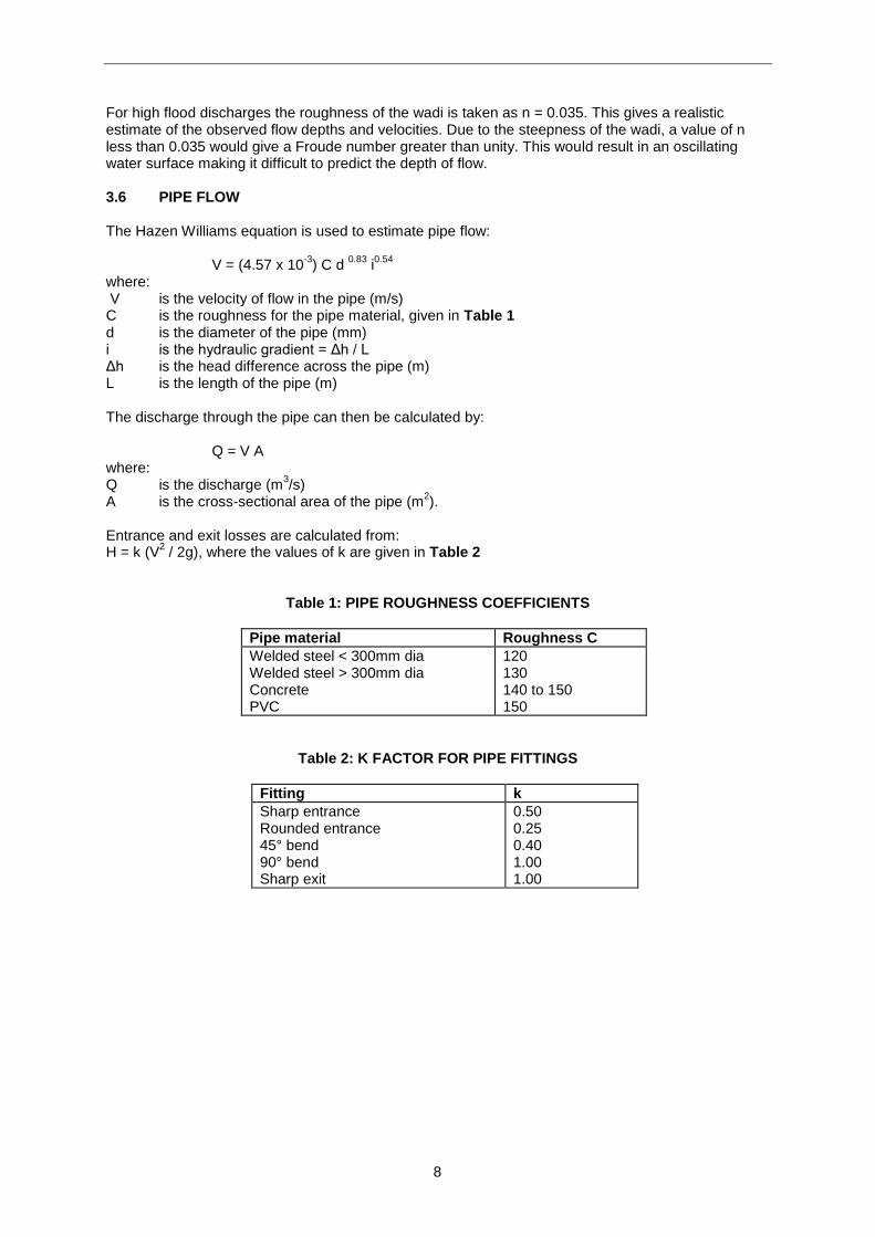
Table 3: COEFFICIENTS FOR WEIGHTED CREEP & EXIT GRADIENT
Material Lane’s C Exit Gradient
SILT Fine SAND Medium SAND Coarse SAND Fine GRAVEL Medium GRAVEL Coarse GRAVEL BOULDERS and gravel Soft CLAY Medium CLAY Hard CLAY
8.5 7.0 6.0 5.0 4.0 3.5 3.0 2.5 3.0 2.0 1.8
1/6 1/5 1/5 1/5 1/5 1/4.5 1/4.5 1/4.5 1/3 1/2.5 ½
4.2 THICKNESS OF CONCRETE TO RESIST UPLIFT The thickness of concrete at the particular point under consideration resisting the uplift pressure under the no flow condition (case(a)) is determined from: T a = F x H r / ( d c - d w ) Where Ta is the thickness of concrete at that point in metres F is the factor of safety, taken as 1.2 under normal design and reduced to 1.0 under the
condition of a joint failure Hr is the residual uplift head at that point in metres dc is the specific gravity of concrete = 2.4 dw is the specific gravity of water = 1.0. When a hydraulic jump forms in the basin under the maximum flow condition (case (b)) the thickness of concrete is determined from: Tb = F x H b / ( d c - d w ) where Tb is the thickness of concrete at the point of the hydraulic jump The other parameters are as defined above. The concrete thickness to be adopted for the structure is the greater of Ta or Tb.
4.3 SCOUR PROTECTION The depth of scour is calculated using Lacey’s formula: Ds = XR -Y Where Ds = the scour depth below bed level in m X = the severity factor depends on the type of reach (see Table D2) Y = the depth of flow in the channel in m R = 1.35 (q
2 /f )
1/3
q = the unit discharge m3/s/m
f = Lacey’s silt factor (see Table D1), where f = 1.76 d501/2
The appropriate silt factor to applied in the downstream reaches of the wadi is between f = 3 to 5.

11
The types of scour protection used are gabion mattresses and tied concrete blocks. For designing the extents of the scour protection works launching aprons are used as follows: The minimum length of the launching aprons are 2Ds downstream of the weir and 1.5Ds upstream of the weir, where Ds is the scour depth in metres. The depth of the structure cut offs is to be greater than the calculated scour depth.
Table 4: SILT FACTOR COEFFICIENTS
Material Average d50 size (mm)
Silt factor f
Very fine SILT Fine SILT Medium SILT Standard SILT Medium SAND Coarse SAND Fine GRAVEL Medium GRAVEL Heavy GRAVEL Small BOULDERS Medium BOULDERS Large BOULDERS
0.05 0.12 0.15 0.32 0.50 0.72 1.30 7.30 26 50 72 185
0.4 0.5 0.7 1.0 1.2 1.5 2.0 4.7 9.0 12.0 15.0 24.0
Table 5: SEVERITY FACTOR COEFFICIENTS
Location Severity factor X
Upstream of structure Downstream of structure Nose of spur Transition from nose to straight Straight reach of guide bank
1.5 2.0 2.25 1.5 1.25
12
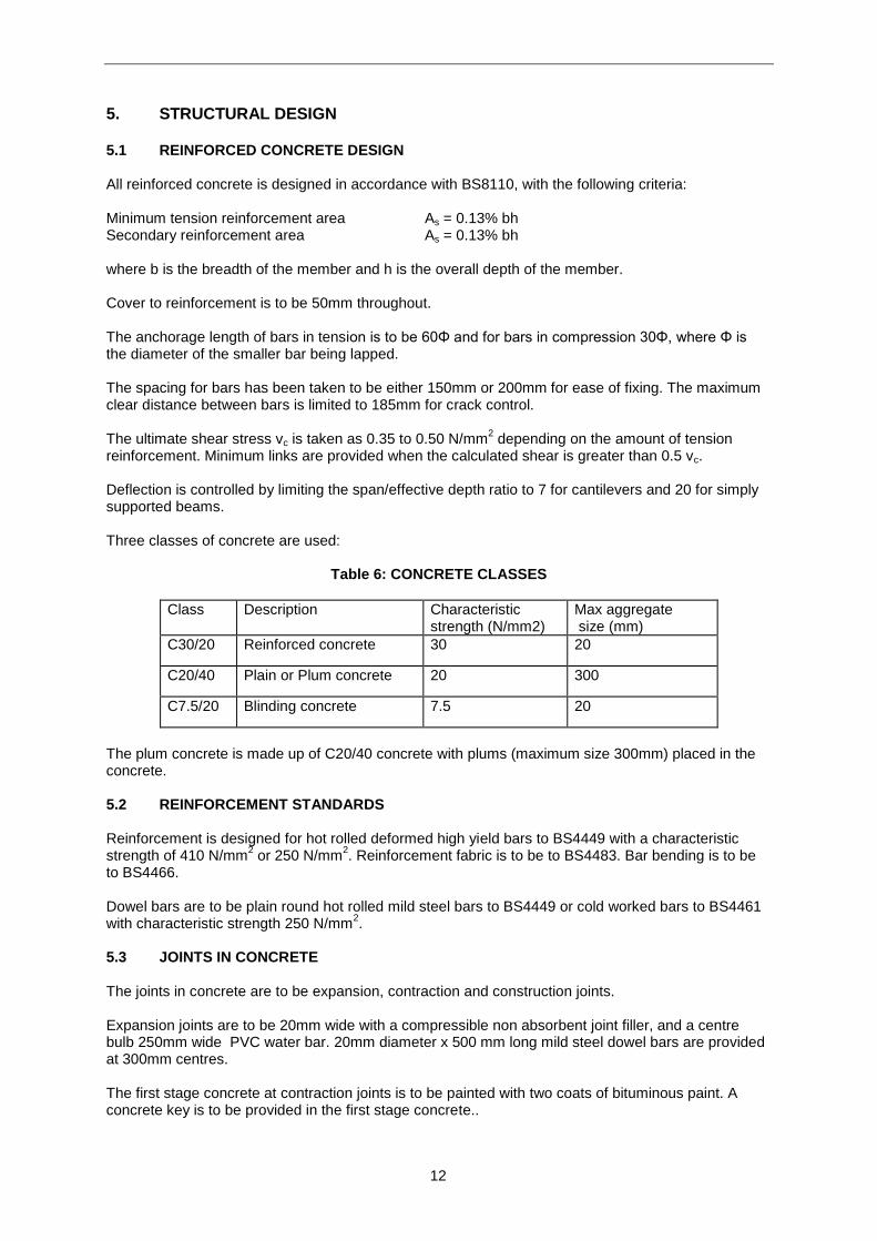
5. STRUCTURAL DESIGN 5.1 REINFORCED CONCRETE DESIGN All reinforced concrete is designed in accordance with BS8110, with the following criteria: Minimum tension reinforcement area As = 0.13% bh Secondary reinforcement area As = 0.13% bh where b is the breadth of the member and h is the overall depth of the member. Cover to reinforcement is to be 50mm throughout. The anchorage length of bars in tension is to be 60Φ and for bars in compression 30Φ, where Φ is the diameter of the smaller bar being lapped. The spacing for bars has been taken to be either 150mm or 200mm for ease of fixing. The maximum clear distance between bars is limited to 185mm for crack control. The ultimate shear stress vc is taken as 0.35 to 0.50 N/mm
2 depending on the amount of tension
reinforcement. Minimum links are provided when the calculated shear is greater than 0.5 vc. Deflection is controlled by limiting the span/effective depth ratio to 7 for cantilevers and 20 for simply supported beams. Three classes of concrete are used:
Table 6: CONCRETE CLASSES
Class Description Characteristic strength (N/mm2)
Max aggregate size (mm)
C30/20 Reinforced concrete 30 20
C20/40 Plain or Plum concrete 20 300
C7.5/20 Blinding concrete 7.5 20
The plum concrete is made up of C20/40 concrete with plums (maximum size 300mm) placed in the concrete. 5.2 REINFORCEMENT STANDARDS Reinforcement is designed for hot rolled deformed high yield bars to BS4449 with a characteristic strength of 410 N/mm
2 or 250 N/mm
2. Reinforcement fabric is to be to BS4483. Bar bending is to be
to BS4466. Dowel bars are to be plain round hot rolled mild steel bars to BS4449 or cold worked bars to BS4461 with characteristic strength 250 N/mm
2.
5.3 JOINTS IN CONCRETE The joints in concrete are to be expansion, contraction and construction joints. Expansion joints are to be 20mm wide with a compressible non absorbent joint filler, and a centre bulb 250mm wide PVC water bar. 20mm diameter x 500 mm long mild steel dowel bars are provided at 300mm centres. The first stage concrete at contraction joints is to be painted with two coats of bituminous paint. A concrete key is to be provided in the first stage concrete..

13
At contraction joints in plum concrete, plums are to extend only up to 300mm from the centre line of the joint. Expansion and contraction joints are to be sealed with a 20 x 20mm polysulphide sealant at the exposed faces of the joints. Expansion and contraction joints are to be continued through any masonry cladding with a gap of 20mm. Horizontal and vertical construction joints in the body of the plum concrete weir will depend on the size of the concrete pour. These joints are to be scabbled and loose concrete removed before the next pour. At joints between plum concrete or masonry and reinforced concrete 20mm diameter x 750mm long mild steel dowels are to be cast into the reinforced concrete at 500mm centres to facilitate a key. The coefficient of expansion of concrete is taken as 10 x 10
-6 per degree C. Assuming a temperature
change of 50 degrees gives a 20mm expansion over a 40m length of concrete. As a factor of safety an expansion joint is to be provided every 20m. The coefficient of expansion of masonry cladding can vary between 2 to 12 x 10
-6 per degree C. The differential movement between the concrete and
masonry cladding is to be taken up in the masonry joints. In the case of small canal structures expansion joints are deemed not to be required and any differential movement will be absorbed by the contraction joints. 5.4 BRIDGE LOADING STANDARDS Loading for bridges has been taken as follows: 1) for bridge loading a HA loading is applied. This consists of a 10 kN/m uniformly distributed
load per metre width of bridge and a 40 kN/m width of bridge point load at mid span. 2) for the footbridge a 5kN/m
2 imposed load is applied.
In accordance with BS5400, the partial factors of safety for ultimate limit state are taken as 1.5 for the imposed load and 1.15 for the dead load. For loading on breast walls hydrostatic, hydrodynamic and impact loads are considered. The impact load is taken as 50 kN. For loading of reinforced concrete retaining walls earth pressure, hydrostatic, surcharge. The surcharge load is taken as 10kN/m
2 .
The following partial safety factors for loads are applied:
Table 7: PARTIAL SAFETY FACTORS FOR BRIDGE LOADING
Loading Type Ultimate Limit State Serviceability Limit State Dead load 1.4 1.0 Earth pressure load 1.4 1.0 Fluid pressure 1.4 1.0 Imposed load 1.6 1.0 Seismic load 1.0 1.0 Dead load for bridge 1.15 1.0 Imposed load for bridge 1.50 1.2

14
5.5 MASONRY WALLS Two types of masonry are to be used:
Table 8: TYPES OF MASONRY
Type Description Location
SRCM Square Rubble Coursed Masonry, dressed stone with pointed joints and 25mm thick mortar.
As cladding to masonry walls in places not exposed to aggressive flow.
RRUM Random Rubble Uncoursed Masonry, bedded in mortar with a bond stone every square metre.
Where masonry walls are to be backfilled or as core infill to walls.
Parameters used for the design of masonry walls are as follows: density of masonry 25kN/m
3
maximum allowable compressive strength in masonry 1 N/mm2
maximum allowable tensile strength in masonry 0.1 N/mm2
frictional angle at masonry/concrete interface 33°
15
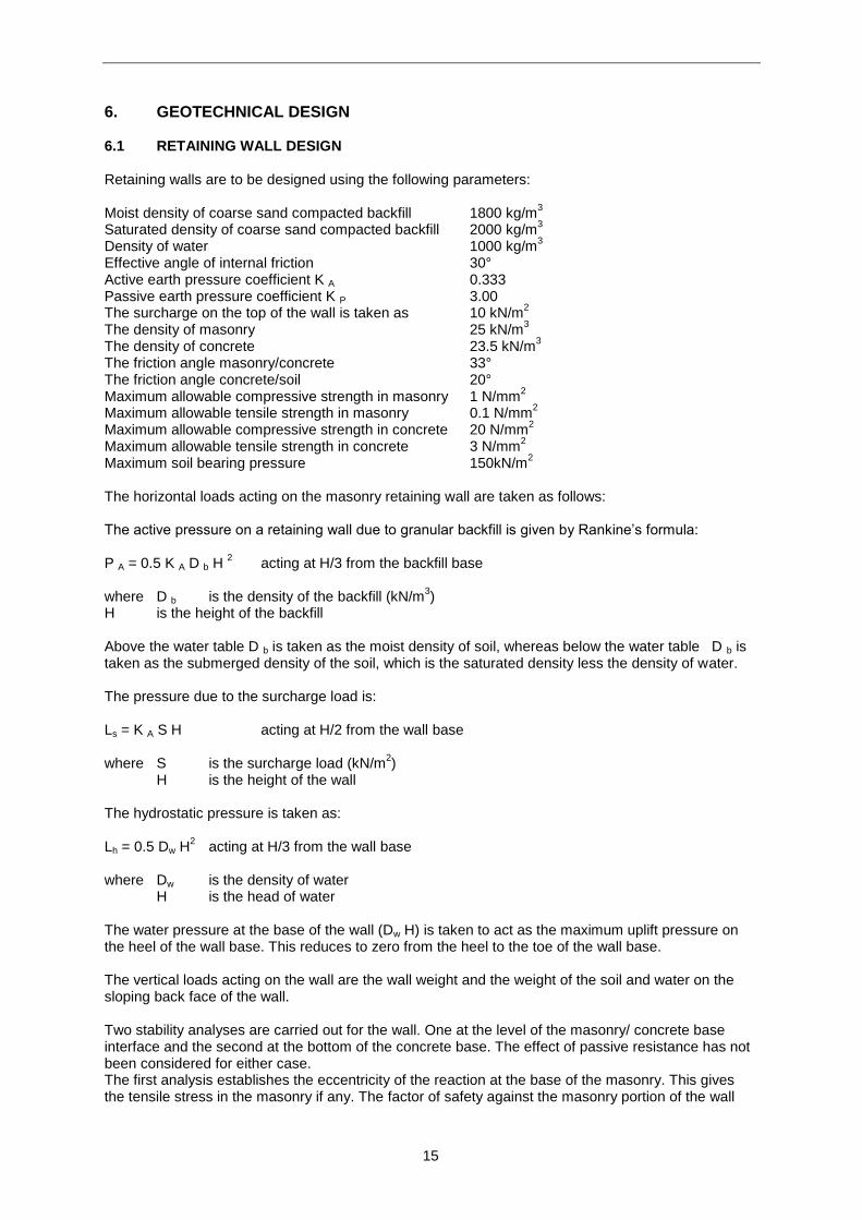
6. GEOTECHNICAL DESIGN 6.1 RETAINING WALL DESIGN Retaining walls are to be designed using the following parameters: Moist density of coarse sand compacted backfill 1800 kg/m
3
Saturated density of coarse sand compacted backfill 2000 kg/m3
Density of water 1000 kg/m3
Effective angle of internal friction 30° Active earth pressure coefficient K A 0.333 Passive earth pressure coefficient K P 3.00 The surcharge on the top of the wall is taken as 10 kN/m
2
The density of masonry 25 kN/m3
The density of concrete 23.5 kN/m3
The friction angle masonry/concrete 33° The friction angle concrete/soil 20° Maximum allowable compressive strength in masonry 1 N/mm
2
Maximum allowable tensile strength in masonry 0.1 N/mm2
Maximum allowable compressive strength in concrete 20 N/mm2
Maximum allowable tensile strength in concrete 3 N/mm2
Maximum soil bearing pressure 150kN/m2
The horizontal loads acting on the masonry retaining wall are taken as follows: The active pressure on a retaining wall due to granular backfill is given by Rankine’s formula: P A = 0.5 K A D b H
2 acting at H/3 from the backfill base
where D b is the density of the backfill (kN/m
3)
H is the height of the backfill Above the water table D b is taken as the moist density of soil, whereas below the water table D b is taken as the submerged density of the soil, which is the saturated density less the density of water. The pressure due to the surcharge load is: Ls = K A S H acting at H/2 from the wall base where S is the surcharge load (kN/m
2)
H is the height of the wall The hydrostatic pressure is taken as: Lh = 0.5 Dw H
2 acting at H/3 from the wall base
where Dw is the density of water
H is the head of water The water pressure at the base of the wall (Dw H) is taken to act as the maximum uplift pressure on the heel of the wall base. This reduces to zero from the heel to the toe of the wall base. The vertical loads acting on the wall are the wall weight and the weight of the soil and water on the sloping back face of the wall. Two stability analyses are carried out for the wall. One at the level of the masonry/ concrete base interface and the second at the bottom of the concrete base. The effect of passive resistance has not been considered for either case. The first analysis establishes the eccentricity of the reaction at the base of the masonry. This gives the tensile stress in the masonry if any. The factor of safety against the masonry portion of the wall

16
sliding on the concrete base is also checked. The second analysis establishes the eccentricity of the soil reaction, the tension within the concrete, the maximum bearing pressure and the stability against sliding. The following formulae are used: the position of the resultant from the heel of the base x = M/Rv where M = Mh + Mv Mh is the sum of the horizontal moments about the heel of the base Mv is the sum of the vertical moments about the heel of the base Rv is the sum of the vertical loads. If x is within the middle third of the base there is no negative pressure on the base, hence no tension in the masonry or concrete. The pressure at the base is calculated from: P = Rv { 1 ± ( 6 e / B) } B where P is the maximum and minimum pressure on the base, which is used to calculate the vertical stress. B is the base width e is the absolute difference ( x - B/2) The FOS against sliding = Rv Tanø Rh where Rh is the sum of the horizontal loads ø is the friction angle To calculate the bending stress in the concrete base the following equation is applied: σ = M/Z where σ is the bending stress M is the moment in the base at the junction where the masonry meets the base calculated from
the pressure distribution under the base Z is the section modulus = I/y y is the distance from the neutral axis to the outer edge of the base = d/2 I is the moment of inertia = bd
3/12
b is the width of the base d is the depth of the base The factors of safety (FOS) applied to the retaining wall analysis are as follows: FOS against overturning: The wall is considered to be safe provided that the soil reaction is within the middle third of the base and that the soil bearing pressure does not exceed the allowable 150 kN/m
2.
FOS against stress failure: The tension and bending stress within the mass concrete base does not exceed 2N/mm
2 (for concrete
with a characteristic strength of 20 N/mm2). This is a FOS of 1.5 on the allowable tensile stress from
literature, which is quoted as 3 N/mm2. The compressive strength within the concrete is limited to the
characteristic strength. Tension within the masonry portion is limited to 0.1 N/mm
2 which represents a FOS of 1.5 over other
quoted tensile stress limits. Compressive stress within the masonry is limited to 1 N/mm2, with is a
FOS of 2.5 over other quoted sources.

17
FOS against sliding: This is taken as 1.2. Since passive resistance of the cut- offs is ignored this is deemed to be an adequate FOS. 6.2 BEARING CAPACITY The bearing capacity has been calculated from the Terzaghi equation for a shallow strip footing modified with shape factors for a square foundation as follows: qf = 0.4γ B N + 1.2 c Nc + D Nq where qf is the ultimate bearing capacity γ is the submerged density of the soil, taken as 10 kN/m
2
B is the minimum footing width, taken as 3m N is a bearing capacity factor = 19, (for ø +30°) c is the cohesive strength = 0 for granular soil Nc is a bearing capacity factor = 30, (for ø = 30°) D is the depth of the foundation, taken as 1.5 m Nq is a bearing capacity factor =19, for (ø = 30°) The value of qf is calculated to be about 250kN/m
2, and a FOS = 1.5 is applied to obtain the allowable
bearing capacity qa = 170 kN/m2. Note that 150 kN/m
2 is used in the stability calculations.

Annex 1
DRAFTING STANDARDS

Annex 1: DRAFTING STANDARDS Overall Layout and Size OF Drawings Drawings are nominally A1 size, but will normally be printed at A3 for ease of copying and distribution. The drawing should be sized to print at half-scale on an A3 laser printer, after allowing for non-printable margins. At A1 size, the drawing scales, details, line thicknesses and lettering will be similar to what would be drawn manually using pen and ink. Lettering will typically be 2.5mm to 8mm high at A1 size (ie 1.25 to 4mm high at A3). Printing at A3 size gives drawings which are easier to copy, distribute and file. However, some care is needed to ensure that the A3 drawings can be read easily. Drawing Scales The following table details the preferred drawing scales derived from BS EN ISO 5455:1994. If further scales are required, the preferred range may be extended, provided that the required scale is derived from a preferred scale by multiplying by whole number powers of 10. These are the scales appropriate to the nominal (A1) size drawing. Scales at A3 size will be double, ie 1:10 at A1 becomes 1:20 at A3. Table 1 – Preferred Drawing Scales 1:1 1:10 1:100 1:1000 1:10000 etc 1:2 1:20 1:200 1:2000 1:20000 etc 1:5 1:50 1:500 1:5000 1:50000 etc To supplement the ‘preferred’ drawing scales the following scales shown in Table 2 may be use for cartographic based plans and details when necessary. Table 2 – Cartographic Drawing Scales 1:1250 1:2500 1:12500 1:25000 1:12500 The following drawing scales, show in Table 3, are non-preferred. These scales should only be used in exceptional cases. Table 3 – Non-preferred Drawing Scales 1:12.5 1:25 1:125 1:250 Scale Bars Scale bars shall be provided on all drawings. They shall be located above the title box. One scale bar shall be provided for each scale used on the drawing. Each scale bar will be labelled with both the A1 and A3 scales. Unless a drawing uses only one scale, each component of a drawing shall show its scale underneath its heading. This scale shall be the scale at A1. When the drawing has only one scale, the value shall be stated in the scale box underneath the drawing title. If a drawing uses more than one scale then “As shown” shall be written in the scale box.
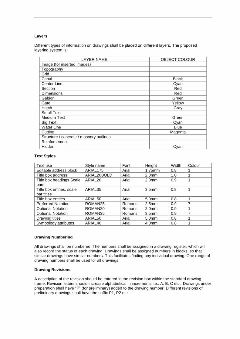
Layers Different types of information on drawings shall be placed on different layers. The proposed layering system is:
LAYER NAME OBJECT COLOUR
Image (for inserted images)
Topography
Grid
Canal Black
Center Line Cyan
Section Red
Dimensions Red
Gabion Green
Gate Yellow
Hatch Gray
Small Text
Medium Text Green
Big Text Cyan
Water Line Blue
Cutting Magenta
Structure / concrete / masonry outlines
Reinforcement
Hidden Cyan
Text Styles
Text use Style name Font Height Width Colour
Editable address block ARIAL175 Arial 1.75mm 0.8 1
Title box address ARIAL20BOLD Arial 2.0mm 1.0 1
Title box headings Scale bars
ARIAL20 Arial 2.0mm 0.9 1
Title box entries, scale bar titles
ARIAL35
Arial 3.5mm 0.8 1
Title box entries ARIAL50 Arial 5.0mm 0.8 1
Preferred Notation ROMAN25 Romans 2.5mm 0.9 7
Optional Notation ROMAN20 Romans 2.0mm 0.9 1
Optional Notation ROMAN35 Romans 3.5mm 0.9 7
Drawing titles ARIAL50 Arial 5.0mm 0.8 1
Symbology attributes ARIAL40 Arial 4.0mm 0.8 1
Drawing Numbering All drawings shall be numbered. The numbers shall be assigned in a drawing register, which will also record the status of each drawing. Drawings shall be assigned numbers in blocks, so that similar drawings have similar numbers. This facilitates finding any individual drawing. One range of drawing numbers shall be used for all drawings. Drawing Revisions A description of the revision should be entered in the revision box within the standard drawing frame. Revision letters should increase alphabetical in increments i.e.. A, B, C etc. Drawings under preparation shall have “P” (for preliminary) added to the drawing number. Different revisions of preliminary drawings shall have the suffix P1, P2 etc.
Cross References Cross references between drawings shall be clearly shown by:
(a) Relevant drawings shall be listed in the notes (b) Sections shown on other drawings shall be shown using both the section letter and
drawing number. If the section is on the current drawing, then put a dash ( – ) instead of drawing number.
(c) Details shall be labelled with a detail number and drawing number in a circle. If the detail is on the current drawing, then put – instead of drawing number.
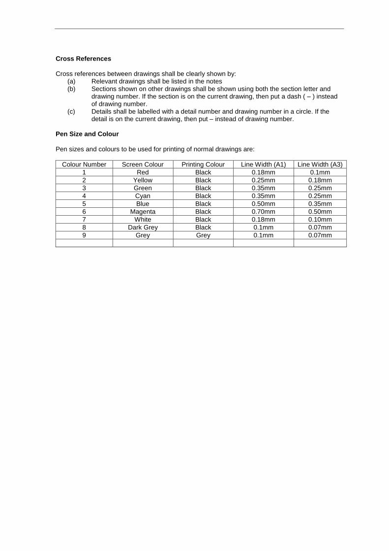
Pen Size and Colour Pen sizes and colours to be used for printing of normal drawings are:
Colour Number Screen Colour Printing Colour Line Width (A1) Line Width (A3)
1 Red Black 0.18mm 0.1mm
2 Yellow Black 0.25mm 0.18mm
3 Green Black 0.35mm 0.25mm
4 Cyan Black 0.35mm 0.25mm
5 Blue Black 0.50mm 0.35mm
6 Magenta Black 0.70mm 0.50mm
7 White Black 0.18mm 0.10mm
8 Dark Grey Black 0.1mm 0.07mm
9 Grey Grey 0.1mm 0.07mm

Annex 2
Contents of Design CD-ROM

Annex 2: CONTENTS OF DESIGN CD-ROM During his input in July/August 2008, the Consultant’s River Training Engineer provided TDA with a CD-ROM containing the following technical references and publications.
Title
Guidelines for Wadi Diversion and Protection Works
Workshop Presentations
Session 1 : Understanding the Wadis
Session 2 : Improving Diversion Works
Session 3 : Channel Stability and Bank Protection
Selected Drawings from Irrigation Improvement Project
USBR Design of Small Dams
USBR Design of Small Canal Structures
USBR Earth Manual
USBR Hydraulic Design of Stilling Basins and Energy Dissipators
USACE Hydraulic Design of Flood Control Channels
FAO Small Dams and Weirs in Earth and Gabion Materials
FAO Small Hydraulic Structures
Maccaferri Brochure on Gabions and Reno Mattresses
Maccaferri Flexible Gabion Structures in River and Stream Training Works
IIP Working Paper26 - Options for Zabid Main Canals
Proceedings of the 1987 Spate Irrigation Conference in Aden
HR Wallingford Report OD 154 : Improving Community Spate Irrigation
HR Wallingford Report OD 73 : Wadi Zabid Diversion Structures - Field Performance Measurements
IIP Working Paper 25 – Hydrology
Related Documents