Minimax GmbH 99-0500-03/30.10.03 Page1 ARGOTEC ® EXTINGUISHING SYSTEM DESIGN MANUAL 99-0500-03 Minimax GmbH Copy Number: Holder: UL File EX5248

Welcome message from author
This document is posted to help you gain knowledge. Please leave a comment to let me know what you think about it! Share it to your friends and learn new things together.
Transcript

Minimax GmbH 99-0500-03/30.10.03 Page1
ARGOTEC® EXTINGUISHING SYSTEM
DESIGN MANUAL
99-0500-03
Minimax GmbH
Copy Number: Holder:
UL File EX5248

Minimax GmbH 99-0500-03/30.10.03 Page2
CONTENTS1. INTRODUCTION 8
1.1. Foreword 81.2. Applicable Standards 9
2. DEFINITIONS 10-113. ARGON TECHNICAL DATA 12
3.1. Introduction 123.2. Argon Data 123.3. Argon IG-01 Specification 123.4. Availability of Argon 13
4. PERSONNEL SAFETY 144.1. General 144.2. Hazard Due to Reduced Oxygen 144.3. Exposure to Fire 154.4. Hazards During Discharge 154.5. NOEL and LOEL 15
Graph 1. Argon/Oxygen Comparison concentration Levels 165. SAFETY PRECAUTIONS 17
5.1. Safety Warning Signs, Alarms and Controls 175.2. Audible and Visual Alarms 175.3. Warning Sign - Manual Release 185.4. Warning Sign - Entrances 185.5. System Isolation for Maintenance 185.6. Discharge Prevention Device and Isolation 18
Fig. 1 Safety Sign - less than 60 seconds evacuation 19Fig. 2 Safety Sign - over 60 seconds evacuation 20Fig. 3 Safety Sign - isolate valve closed 21
5.7. Change in Protected Area Volume 225.8. Leakage of Argon into Adjacent Areas 225.9. Other Safety Considerations 225.10. Ventilation After Discharge 235.11. Electrostatic Discharge. 23
6. SYSTEM DESIGN PHILOSOPHY 246.1. General 246.2. Fire Extinguishing with Argon 246.3. Limitations of Use 246.4. Minimum Design Concentration 256.5. Unusual Risks 256.6. System Discharges into Non Fire Areas 256.7. Information Relating to the Protected Area 266.8. Minimum Data Required 266.9. System Design Considerations 276.10. Detection and Control Systems 28
Minimax GmbH 99-0500-03/30.10.03 Page3
CONTENTS7. SYSTEM CONFIGURATION 29
7.1. General 297.2. Cylinder Bank 297.3. Cylinder Racking 297.4. Manifolds 297.5. Pressure Reducer 297.6. Pilot Cylinder Actuator 297.7. Cascade Delay Unit 307.8. Pressure Operated Devices 307.9. Nozzles 30
7.10. Data Sheet for System Components 30-31 Data sheets8. DESIGN CALCULATIONS 32
8.1. Argon Quantity Calculation 32 8.2. Argon Concentration Check 32
8.3. Alternative Quick Calculation 338.4. Example Calculation 348.5. Interconnected Volumes 358.6. Uncloseable Openings 358.7. Forced Ventilation 368.8. Altitude Adjustment 368.9. Requirements for Deep Seated Fires 378.10. Selection of Cylinders 378.11. Discharge Times 388.12. Computer Calculation 39
9. NOZZLE SELECTION 409.1. Area of Coverage 409.2. Floor and Ceiling Voids 409.3. Quantity of Nozzles 40
Graph 2 Nozzle Determination 42 9.4. Pressure Relief Calculation 43-45
Graph 3 Pressure Relief Calculation to Determine Flow Factor 46Graph 4 Argon Pressure / Temperature Graph 4710. PIPEWORK AND FITTINGS 48
10.1. General 4810.2. Flanges 4810.3. Fittings 4810.4. Pipe Layout within Protected Area 52
Drawing 1 Pipe Isometric Diagram 5310.5. Pipe Size Calculation 54
Graph 5-12 Pipe Sizing Graphs 55-62 10.6 Equivalent Length of Pipe Fittings 64

Minimax GmbH 99-0500-03/30.10.03 Page4
CONTENTS11. REFERENCE DOCUMENTATION 65 VdS Certificates Institute of Hygiene12. INSTALLATION OF PIPEWORK 6613. SAMPLE PROBLEM 67-76

Minimax GmbH 99-0500-03/30.10.03 Page5
TABLE INDEX
TABLE 1 Relative Hazards to People from Reduced Levels of Oxygen 14
TABLE 2 NOEL and LOEL Values 15
TABLE 3 Minimum Requirements for Occupied Spaces 22
TABLE 4 Flooding Factors 33
TABLE 5 Argotec® Design Concentrations 34
TABLE 6 Argon Design Concentrations for Gases and Liquids 35
TABLE 7 Altitude Correction Factors 37
TABLE 8 Selection of Cylinders 37
TABLE 9 Minimum Pipe Wall Thickness/ScheduleUpstream of Pressure Reducer/Isolation Valve Screwed Fittings 160 bar 49
TABLE 10 Minimum Pipe Wall Thickness/ScheduleUpstream of Pressure Reducer/Isolation Valve Screwed Fittings 200 bar 50
TABLE 11 Minimum Pipe Wall Thickness/ScheduleDownstream of Pressure Reducer/Isolation Valve Screwed Fittings 51
TABLE 12 Electrical Safety Clearances 63
TABLE 13 Selector Valve Equivalent Lengths 63
TABLE 14 Equivalent Length of Pipe Fittings 64

Minimax GmbH 99-0500-03/30.10.03 Page6
FIGURE INDEX
FIGURE 1 Safety Sign - less than 60 seconds evacuation 19
FIGURE 2 Safety Sign - over 60 seconds evacuation 20
FIGURE 3 Safety Sign - isolate valve closed 21
FIGURE 4 Nozzle location limitation 43

Minimax GmbH 99-0500-03/30.10.03 Page7
GRAPH INDEX
GRAPH 1 Argon/Oxygen Comparison Concentration Levels 16
GRAPH 2 Nozzle Determination 42
GRAPH 3 Pressure Relief Calculation to Determine Flow Factor 46
GRAPH 4 Argon Cylinder Pressure / Temperature 47
GRAPH 5-12 Pipe Sizing Graphs 55-62

Minimax GmbH 99-0500-03/30.10.03 Page8
1. INTRODUCTION
1.1 Foreword
Argotec® Extinguishing Systems using Argon gas, internationally known as extinguishant IG-01, are manufactured by Minimax GmbH.
The manual is to be used by qualified and trained personnel who design, install and maintainthe company's Argotec® systems and as a guide in the effective application of such systems.
The importance of proper design cannot be over stressed, as design concentrations, applicationrates, pressure venting and agent retention must be addressed correctly to ensure successful fireextinguishing and personnel safety.
The information contained in this manual is based on known technical data. While the aim hasbeen to anticipate most applications the recommendations should be applied in practicalsituations with discretion and due regard to actual local circumstances.
For installation and maintenance see installation and maintenance manual 99-0600-03.
IMPORTANT
Minimax GmbH assumes no responsibility for application of any system other than thoseaddressed in this manual. The technical data contained herein is limited strictly forinformation purposes only. Minimax GmbH believes this data to be accurate, but it ispublished and presented without any guarantee or warranty whatsoever. MinimaxGmbH disclaims any liability for any use that may be made of the data and informationcontained herein by any and all other parties.
Any questions concerning the information presented in this manual should be addressed to:
Minimax GmbH Industriestr. 10-12
23840 Bad Oldesloe Germany
Tel: +49 (0) 4531 - 803 0
Fax +49 (0) 4531 - 803 248

Minimax GmbH 99-0500-03/30.10.03 Page9
1.2 Applicable Standards
Argotec®, IG-01, extinguishing systems are to be designed, installed, inspected, maintained,tested and recharged by qualified and trained personnel in accordance with the following:
a) NFPA 2001 latest edition : Clean Agent Fire Extinguishing Systems
and additional if required
ISO Standard/DIS 14520 : Gaseous Fire Extinguishing systems
and additional if required
Other recognised National or International code or standard specified by the end user.
b) All instructions and limitations contained in this manual.
c) All information contained on the Argotec® cylinder nameplate(s).
d) NFPA 70, National Electrical Code, and NFPA 72, National Fire Alarm Code.
e) The US EPA SNAP program.
f) Regulations imposed by the Authority having jurisdiction for the hazard to be protected.

Minimax GmbH 99-0500-03/30.10.03 Page10
2. DEFINITIONSFor purpose of clarification, the following general terms used have special technical meaningsin this Manual.
Automatic/Manual Changeover Device
An electrical switch which can change the electrical firing signal for the Argotec® cylinderbank, to either automatic and manual mode or manual only mode of operation. The switchwould normally be key operated.AuthorityThe organisation, office or individual responsible for approving equipment, installations orprocedures.In determining the acceptability of installations or procedures, equipment or materials, theauthority may base acceptance on compliance with the appropriate design standards.ClientThe person or organisation purchasing the system who will take over initial responsibility forthe equipment and to whom the manuals will be provided. The client may not be the ultimatesystem user.Design ConcentrationConcentration of extinguishant necessary to extinguish a fire of a particular fuel, including a20% safety factor for Class A and 30% for Class B fuels expressed as a percentage by volumeof the protected area.ExtinguishantArgon gas, internationally identified as Extinguishant IG-01.Extinguishing ConcentrationMinimum concentration of extinguishant required to extinguish the flame of a particular fuelexcluding any safety factor, expressed as a percentage by volume of the protected area.Gross VolumeVolume enclosed by the building elements around the protected area, less the volume of anypermanent impermeable building elements within the area.Hold TimePeriod of time during which a fire extinguishing concentration must be maintained within theprotected area.Discharge Prevention DeviceA facility which, when in operation, will mechanically either prevent the release of argon fromthe Argotec® cylinders or prevent argon from entering the protected area.

Minimax GmbH 99-0500-03/30.10.03 Page11
Minimum Achievable ConcentrationThe concentration of Argon achieved by the actual quantity released, at the minimumanticipated temperature of the protected area.Maximum Achievable ConcentrationThe concentration of Argon achieved by the actual quantity released, at the maximumanticipated temperature of the protected area.The lowest concentration of extinguishant at which an effect has been observed.LOEL (Low Effect Level)The lowest concentration of extinguishant at which an effect has been observed. Based onphysiologicaleffects in humans in hypoxic atmospheres. The value is the functional equivalentof LOAEL values and correspondent to 10% minimum oxygen.NOEL (No Effect Level)The highest concentration of extinguishant at which no effect has been observed. Based onphysiologicaleffects in humans in hypoxic atmospheres. The value is the functional equivalentof NOAEL values and correspondent to 12% minimum oxygen.
Normally Unoccupied AreaArea not occupied by people , that may be entered occasionally for brief periods, such astransformer bays, switch-houses,.pump rooms, vaults, engine test stands, cable trays, tunnels,microwave relay stations, flammable liquid storage areas and enclosed energy systems.ShallIndicates a mandatory requirement.ShouldIndicates a recommendation or that which is advised but not required.Engineered SystemA system in which the supply of extinguishant is stored in cylinders and is discharged through anetwork of pipe and nozzles in which the size of each section of pipe and nozzle orifice hasbeen calculated. The design flow rates from nozzles may vary according to the designrequirements of the hazard.Total Flooding SystemA fire fighting system arranged to discharge extinguishant into an enclosed space to achieve theappropriate design concentration throughout the protected area.

Minimax GmbH 99-0500-03/30.10.03 Page12
3. ARGON TECHNICAL DATA3.1 Introduction
'Argon' is a naturally occurring inert noble gas which is 1.38 times heavier than air. It ischemically neutral, electrically non-conductive, colourless, odourless and tasteless. It is anormal part of the earth's atmosphere and has no detrimental effect on the environment.Argon has zero ozone depletion potential (ODP) and zero global warming potential (GWP).
ODP GWP
Argon 0 0
It is also considered as a non toxic gas.Argon is internationally identified as "Extinguishant IG-01" and is listed as such inNFPA 2001, ISO/DIS 14520 and the US EPA SNAP program as suitable for use in normallyoccupied spaces.Dry clean air is composed as follows:Nitrogen (N2) = 78.10 Vol.%Oxygen (O2) = 20.90 Vol.%Argon (Ar) = 0.93 Vol.%Carbon Dioxide (CO2) = 0.03 Vol.%Other gases (-) = 0.04 Vol.%
3.2 Argon Data Molecular Weight 39.9 g/mol Density at 1 bar, 15oC 1.669 kg/m3
Specific gas constant (as an ideal gas) 208.13 J/kgK Density ratio Argon/Air at 1 bar, 15oC 1.38 Density ratio Argon/CO2 at 1 bar, 15oC 0.903 Triple point: Temperature -189.2 oC Pressure 0.669 bar Critical point: Temperature -122.43 oC Pressure 48.65 bar Boiling point at 1013 mbar -185.87 oC
3.3 Argon IG-01 Specification Purity 99.9% m/m minimum Acidity 0 Water Content 0.005% by weight maximum Non-volatile residue None
Minimax GmbH 99-0500-03/30.10.03 Page13
Suspended matter (sediment) Non-visible Note - m/m = molecule per molecule
3.4 Availability of Argon Argon is readily available as it is used in several industrial and medical applications. It isproduced by air separation and available from most gas suppliers in various grades i.e. levels ofpurity. The fundamental principle of air separation has three basic stages; pre-purification,refrigeration and separation. Following extraction from the atmosphere the air is purified and compressed with removal ofunwanted components by absorption, freezing out or chemical scrubbing. The air is then pre-cooled in heat exchangers prior to expansion to produce a partial liquefaction of the mixture. The separation of the air components is achieved by use of the different boiling points(liquefaction points) of the gases in the rectification columns where the already liquefiedproduct mixture trickles down to meet the rising gas mixture. Oxygen, having the higher boiling point of -185o C, is condensed out of the gas stream andnitrogen, having the lower boiling point of -196o C vaporises out of the liquid stream. Thus,gaseous nitrogen collects at the top of the column and liquid oxygen at the bottom. The crude argon is drawn from the separation process and undergoes further purity stages untilthe desired quality is attained. After processing, the separated liquid gases are stored in vacuum insulated storage tanks beforebeing loaded into road tankers for distribution.

Minimax GmbH 99-0500-03/30.10.03 Page14
4. PERSONNEL SAFETY4.1 General
Argon gas, by itself, it is not dangerous to animal or human life. It is non toxic and is withoutsecondary reactions in the metabolic processes of animal or human organisms.Physiological data available in scientific and medical literature supports the view that a briefexposure to a mixture of Argon and air resulting in an oxygen concentration in excess of 10%v/v would be tolerated by healthy humans. There is no reason to expect any effect of a briefexposure to such a mixture in terms of cardiac or respiratory sensitisation.Having applied Argon to a fire the toxic risk to personnel safety arises exclusively from thepossibility of inhalation of toxic fumes particles from the combustion processes of the fire.Any hazard to personnel created by the discharge of gaseous extinguishants shall be consideredin the design of the system. Guidance is given in the US EPA SNAP program.Due reference must be made to statutory responsibility to comply with the Health and Safety atWork Act, Control of Substances Hazardous to Health (COSHH) and Pressure SystemsRegulations or any applicable National/European Standards.
4.2 Hazard Due to Reduced Oxygen LevelIt should be recognised that as exposure time increases a temporary impairment of cognitivefunction and the ability to perform skilled or manual tasks is to be expected as the inspiredoxygen level falls below 15%. See Table 1.Table 1 - Relative Hazards to People from Reduced Levels of Oxygen (hypoxia)Source - Paper by A.D. Dayan, Professor of Toxicology - St. Bartholomew Hospital MedicalCollege
OxygenLevel
(% / vol )
Effects and symptoms Rough classificationof the potential ofhazards to people
20,9 Normal inhaled air 19 - 20 None (badly ventilated surroundings)17 - 19 Hardly noticeable, reduced physical and
mental performance capabilityHarmless
15 - 17 Noticeable reduced physical and mentalperformance
Harmless, yawning
12 - 15 Declining performance capability Minor impairment10 - 12 Declining performance capability, shortage
of breath, dizziness, tirednessMarked impairment
8 - 10 Declining performance capability, dangerof collapse and unconsciousness
Hazardous
> 6 Immediate unconsciousness, death within6-8 minutes (fast treatment can save life)
Critical immediateEffects
This table shows the normal effects of short-term exposure without taking into account differences in effects dueto individual personal constitution and other circumstances (health, fitness, hemoglobin levels, stress, physical andmental strains, additional dangerous substances, exposure times etc.)

Minimax GmbH 99-0500-03/30.10.03 Page15
Argon maximum concentrations typically range from 34% to 52% by volume whichcorrespond to oxygen levels of 13.8% to 10% respectfully. The design concentration for atypical class A surface fire is 36,2% of Argon which corresponds to an oxygen level of 13.3%.Unnecessary exposure of personnel to any extinguishant should be avoided by evacuation fromthe protected area prior to discharge.
4.3 Exposure to FireIt must be remembered that exposure to the products of combustion of a fire may have a moreserious health implication and therefore any person subjected to this type of exposure shouldseek medical advice.
4.4 Hazards During Discharge
Users of Argotec® extinguishing systems should be advised of the following potential hazardsdue to discharging Argon gas through the distribution pipe and nozzle network. a) Noise - Discharge of the system causes a loud noise which can be
startling, but not be sufficient to cause traumatic injury. b) Turbulence - Discharge from nozzles could cause some objects within the
protected area to be dislodged, especially if the objects are in direct line of the discharge. Such objects should be properly secured.
c) Temperature - Direct contact with an Argon gas discharge can have a slight cooling effect but is not sufficient to cause frost bite or thermal shock.
4.5 NOEL and LOELThe NOEL, (no effect level) and the LOEL, (lowest effect level) are used in severalinternational standards to establish minimum exposure levels to extinguishant / air mixtures.NOAEL and LOAEL values are normally applied to chemicals with known toxic effects,however, in order that Inert Gas extinguishants can be cross referenced to these standards,functional equivalents have been agreed based upon the physiological effects in humans inhypoxic atmospheresFor Inert Gas extinguishants the NOEL corresponds to an oxygen level of 12% by vol and theLOEL to an oxygen level of 10% by vol.
Table 2 - NOEL and LOEL Values
Level Minimum Level ofOxygen
Equivalent MaximumConcentration of Argon IG-01
NOEL 12% by vol 43% by volLOEL 10% by vol 52% by vol

Minimax GmbH 99-0500-03/30.10.03 Page16
GRAPH 1
Oxy
gen
conc
entr
atio
n by
vol
umen
0
10
20
30
40
50
60
70
80
0,0 0,2 0,4 0,6 0,8 1,0 1,2
Argon volumen per room volumen [m³/m³]
Arg
on c
once
ntra
tion
by v
olum
en
Argon / Oxygen Comparsion Concentration Levels
20
18
16
14
12
10
8
6
20,9
LOEL
NOEL

Minimax GmbH 99-0500-03/30.10.03 Page17
5. SAFETY PRECAUTIONS
5.1 Safety Warning Signs, Alarms and Controls
The Argotec® extinguishing system should be designed in conjunction with the fire detectionand alarm system to ensure that time delays, audible/visual warning alarms, manual releasepoints, safety signs and other associated system requirements will be fully addressed within theoverall system design philosophy.
When the extinguishing system is designed and supplied as a separate package the Argotec®design engineer may not be in possession of specifications relating to the fire detection system,similarly, the audible/visual alarms, time delay arrangements and electric controls required bythe system may be subject to a scope of supply by others. The Argotec® design engineer muststill take responsible steps to ensure that the client is fully aware of the safety aspects requiredfor personnel protection. The following information should therefore be included within thesystem design.
a) The provision of warning notices and appropriate instruction signs at entrances to and inside protected areas that a gaseous system is installed.
b) Pre-discharge alarms and time delay to enable evacuation of personnel before the commencement of discharge.
c) Continuous alarms within entrances to protected areas until the system has been reset by a responsible person.
d) Controls which are used to discharge the system shall be clearly identified with both function and area of risk they effect.
e) Facility to isolate the system during system maintenance. Ideally 'system isolate' should be monitored.
f) When the maximum concentration can be above the LOEL, discharge prevention devices with visual indication must be provided.
5.2 Audible and Visual AlarmsAlarms shall be provided within the protected area to indicate, where applicable:
a) Operation of the fire detection system indicated by audible and visual alarm, distinguishable from the building fire alarm.
b) Commencement of time delay period indicated by an audible alarm different from that in (a) above.
c) Additional visual alarms and signs may be appropriate where there is a high level of background noise.
d) Visual indication of system operation shall be provided outside the protected area at all entrances, and the indicator should be identified with the wording 'ARGON DISCHARGED'.
e) Consideration shall be given to providing alarms and or indication in adjacent areas where hazardous atmospheres may result from the discharge of the extinguishant.

Minimax GmbH 99-0500-03/30.10.03 Page18
5.3 Warning Sign - Manual Control PointA sign shall be prominently displayed at each manual control point.
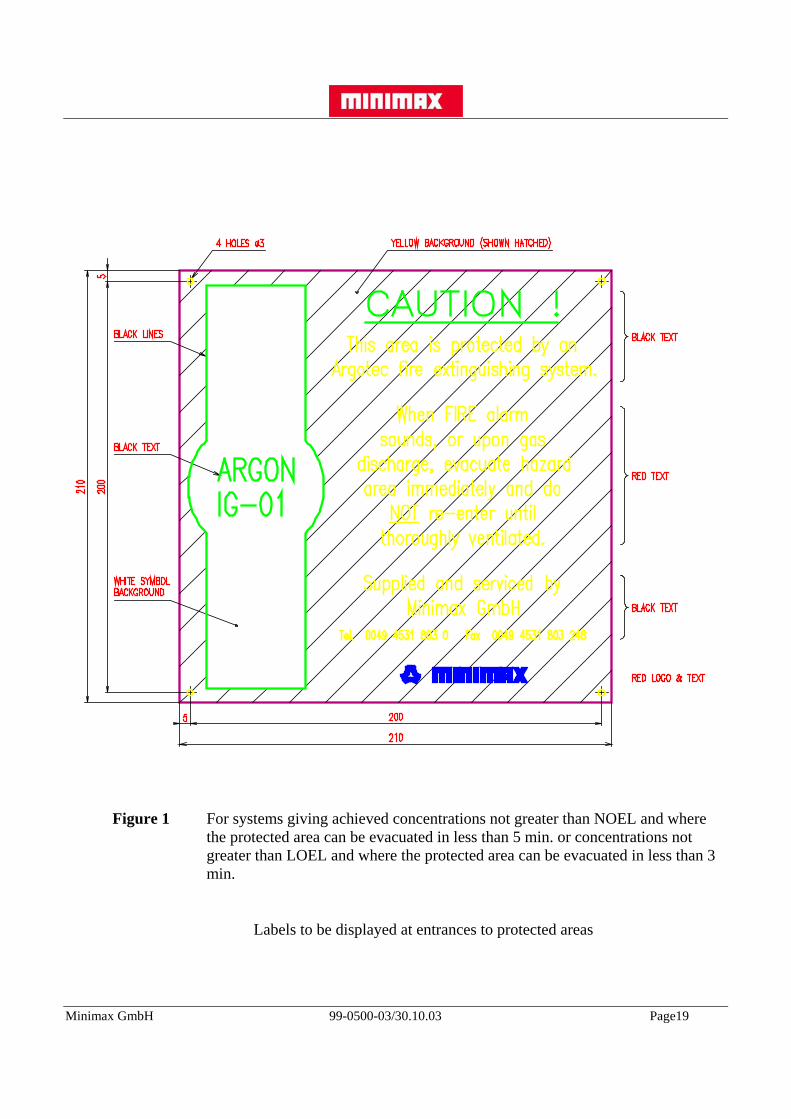
5.4 Warning Sign - EntrancesA sign as shown in Fig. 1 shall be prominently displayed at each entrance to an area protectedby a gaseous system.
A sign as shown in Fig. 2 shall be prominently displayed at each entrance to an area protectedby a gaseous system which develops an achieved concentration not greater than the LOEL, butwhere the protected area evacuation time is 60 seconds or greater.
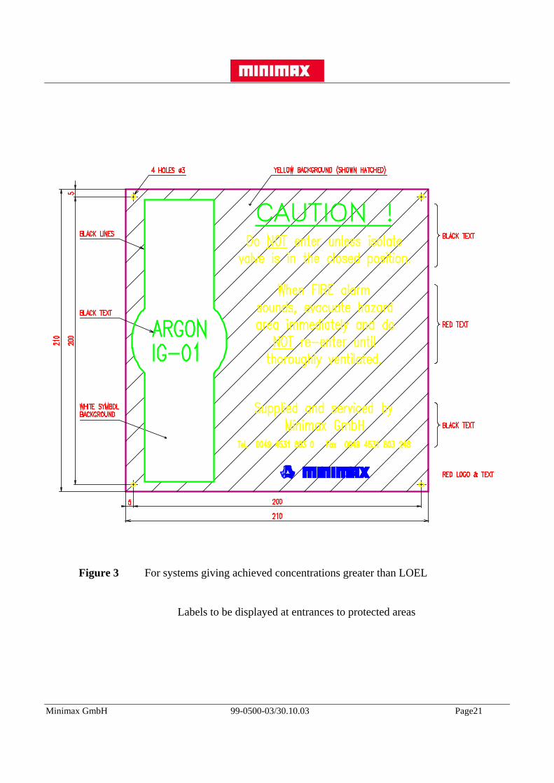
A sign as shown in Fig. 3 shall be prominently displayed at each entrance to an area protectedby a gaseous system which develops an achieved concentration greater than LOEL.
5.5 System Isolation for MaintenanceTo enable system inspection and maintenance to be carried out in safety, means shall beprovided to prevent the discharge from the storage container(s). This ideally should be bymechanical means, such that cylinder valve operation cannot be achieved.
For systems using electrical actuation the normal means to prevent discharge would be toisolate the electrical actuation signal from the extinguishant release control panel. This wouldbe acceptable provided that each cylinder valve actuator is also made mechanically inoperative.
5.6 Discharge Prevention Device and IsolationSystems where the maximum concentration will be below the NOEL (<43%) may remain onautomatic mode at all times. Automatic/manual changeover device should be provided at theextinguishing control panel.
Systems where the maximum concentration will be between the NOEL and LOEL(43 to 52%) can remain on automatic provided the protected area can be evacuated in less than60 seconds. If evacuation time is in excess of 60 seconds the system should be on manual onlymode while the area is occupied. For these systems it is recommended that automatic/manualchangeover devices be provided at all main entrances to the protected area.
Systems where the maximum concentration can be above the LOEL (>52%) a dischargeprevention device must be employed while the protected area is occupied.
This device must mechanically prevent Argon from being discharged into the protected areaand the device status position must be locally indicated.
The discharge of an Argotec® system may be prevented in several ways.
The design engineer must choose the method most suitable for the specific application.
a) Manual shut-off valve with micro-switch, installed into discharge pipework.
b) Key operated pilot line isolation valve with micro-switch, installed between the pilot cylinder and the Argon containers.
Minimax GmbH 99-0500-03/30.10.03 Page19
Figure 1 For systems giving achieved concentrations not greater than NOEL and wherethe protected area can be evacuated in less than 5 min. or concentrations notgreater than LOEL and where the protected area can be evacuated in less than 3min.
Labels to be displayed at entrances to protected areas

Minimax GmbH 99-0500-03/30.10.03 Page20
Figure 2 For systems giving achieved concentrations not greater than LOEL and where the protected area evacuation time is 3 min. or greater.
Labels to be displayed at entrances to protected areas
Minimax GmbH 99-0500-03/30.10.03 Page21
Figure 3 For systems giving achieved concentrations greater than LOEL
Labels to be displayed at entrances to protected areas
Minimax GmbH 99-0500-03/30.10.03 Page22
Caution Notes
It must be observed that if b) method is used the cylinder valve could be manually operated,thus discharging agent into a possible occupied area.
If valves are used in discharge pipework then a safety relief valve must be employed to relieveoverpressure. A pressure gauge should also be introduced to this section of pipe or manifold togive visual indication that the pipe section is pressurized.
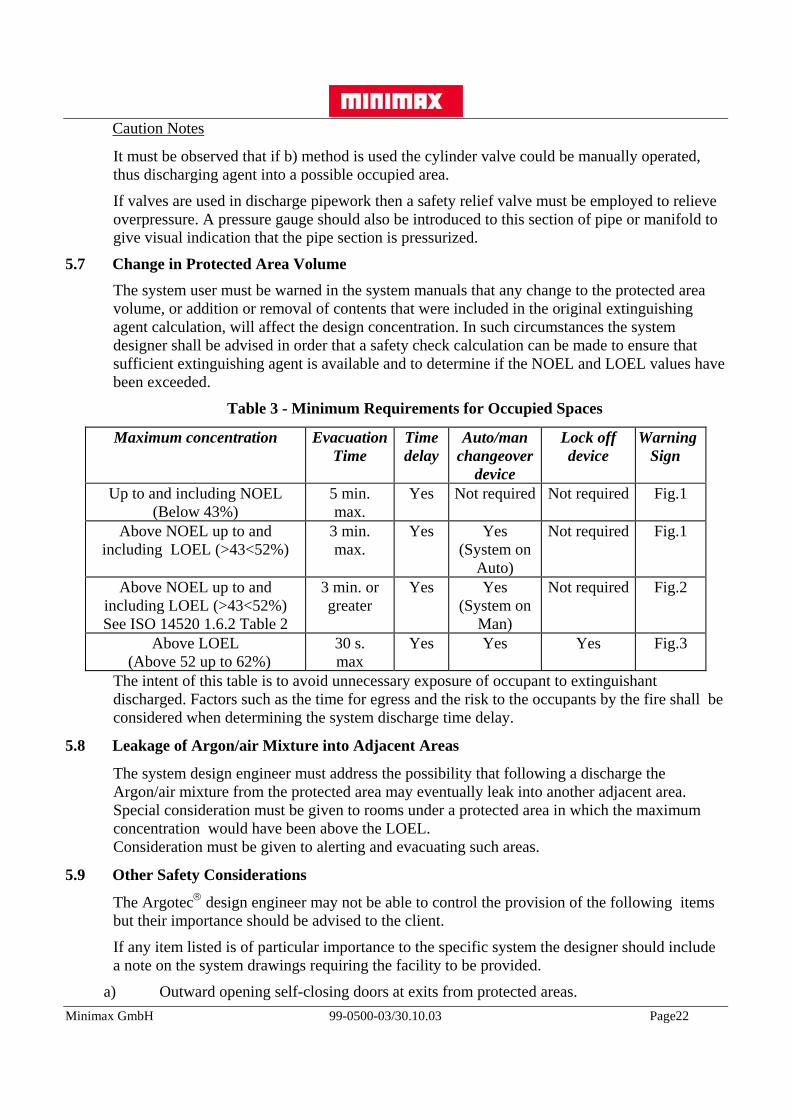
5.7 Change in Protected Area VolumeThe system user must be warned in the system manuals that any change to the protected areavolume, or addition or removal of contents that were included in the original extinguishingagent calculation, will affect the design concentration. In such circumstances the systemdesigner shall be advised in order that a safety check calculation can be made to ensure thatsufficient extinguishing agent is available and to determine if the NOEL and LOEL values havebeen exceeded.
Table 3 - Minimum Requirements for Occupied Spaces
Maximum concentration EvacuationTime
Timedelay
Auto/manchangeover
device
Lock offdevice
Warning Sign
Up to and including NOEL(Below 43%)
5 min.max.
Yes Not required Not required Fig.1
Above NOEL up to andincluding LOEL (>43<52%)
3 min.max.
Yes Yes(System on
Auto)
Not required Fig.1
Above NOEL up to andincluding LOEL (>43<52%)See ISO 14520 1.6.2 Table 2
3 min. orgreater
Yes Yes(System on
Man)
Not required Fig.2
Above LOEL (Above 52 up to 62%)
30 s.max
Yes Yes Yes Fig.3
The intent of this table is to avoid unnecessary exposure of occupant to extinguishantdischarged. Factors such as the time for egress and the risk to the occupants by the fire shall beconsidered when determining the system discharge time delay.
5.8 Leakage of Argon/air Mixture into Adjacent Areas
The system design engineer must address the possibility that following a discharge theArgon/air mixture from the protected area may eventually leak into another adjacent area.Special consideration must be given to rooms under a protected area in which the maximumconcentration would have been above the LOEL.Consideration must be given to alerting and evacuating such areas.
5.9 Other Safety Considerations
The Argotec® design engineer may not be able to control the provision of the following itemsbut their importance should be advised to the client.
If any item listed is of particular importance to the specific system the designer should includea note on the system drawings requiring the facility to be provided.
a) Outward opening self-closing doors at exits from protected areas.

Minimax GmbH 99-0500-03/30.10.03 Page23
b) Adequate aisles and routes of exit which should be clear at all times.
c) Emergency lighting and directional signs as necessary to ensure quick, safe evacuation.
d) Securing of loose objects and ceiling tiles in close proximity to the discharge nozzles.
e) Instruction and training of all personnel within or near protected areas, including maintenance or construction personnel who may be brought into the area, in the correct
action to be taken when gaseous extinguishant equipment operates.
f) Means for post discharge ventilation of protected areas. Forced ventilation may be necessary.
g) Earth bonding of discharge pipework and, in potentially explosive atmospheres, the earthing of conductive materials that may become electrically charged during a system discharge.
h) Provision for prompt discovery and rescue of persons incapacitated in protected areas. Self-contained breathing equipment and personnel trained in its use and in rescue practices, including artificial respiration, should be considered, particularly where the protected area is difficult to egress or where the maximum concentration may exceed the LOEL.
5.10 Ventilation After DischargeThe client must be advised that following the discharge of any gaseous extinguishing systemthe protected area shall be ventilated directly to the open air.
Ventilation may be provided by doors or windows.
Any mechanical ventilation provided should be for extraction only to prevent smoke andextinguishant from being re-circulated to other areas.
With Argon systems consideration must be given to providing the ventilation at low level.
Controls for the ventilation system should be outside the protected area, preferably at thesystem central control panel and should be provided with a notice bearing the wording 'FireBrigade Extinguishant Extraction Switch'. Preference should be given to key operated systems.
5.11 Electrostatic Discharge
Pure, clean and dry Argon gas will not cause "electrostatics" during the discharge. However, itis recognised practice to assume that any gaseous extinguishant could produce static electricityin a given set of circumstances. Refer to 6.6 for further information.

Minimax GmbH 99-0500-03/30.10.03 Page24
6. SYSTEM DESIGN PHILOSOPHY
6.1 General
System designs for Argotec® extinguishing systems should be prepared by a trained engineer.
The system designer must ensure that the extinguishant selected is fit for the proposedapplication and will meet the authority approval.
The system should include all items necessary for its proper function and address clientspecification, relevant national/international codes and standards and the requirements of theauthority.
6.2 Fire Extinguishing with ArgonArgon extinguishes fires mainly by displacing oxygen. The effect, a purely physical one, isremoving the amount of oxygen necessary for combustion of the material in question.
The physical properties of Argon with regard to fire extinguishing are similar to those of CO2.The difference in density between Argon and air give it penetration characteristics whichensure that a fire is efficiently extinguished and that the whole volume of space is protected.
As a rule, an effective concentration for extinguishing purposes is achieved when the normaloxygen concentration in the air of 20.9 % by volume is reduced to less than or equal to 15% byvolume. This level is reached when approximately 1/3 of the volume of air in the room isdisplaced by the inert gas which then accounts for more than or equal to 34% by volume of theambient air. If the room contains materials with a higher than average oxygen affinity thisconcentration will have to be increased.
After the flame has been extinguished it may be necessary to maintain the concentration for awhile until hot surfaces and embers have cooled down, in order to avoid re-ignition.
6.3 Limitations of Use
Argotec® extinguishing systems are suitable for "total flooding" applications including cabinetprotection but are not suitable for "local application" purposes.
Total flooding systems are used to protect fully enclosed hazards that will retain theextinguishant/air mixture for a specified period (Hold Time).
Argon can be used on the following types of fires:
a) Class A- For fires involving solid materials, the minimum design concentration will be the extinguishing concentration established by tests plus a 20% safety factor. Electronic data processing installations are usually regarded as Class A fire risk.
b) Class B - For fires involving flammable liquids and liquifiable solids, the minimum design concentration will be the extinguishing concentration established by tests, or in the absence of tests then by cup burner apparatus with adjustment as specified inTable 6, plus a 30% safety factor. For combinations of fuels the minimum designconcentration will be the highest extinguishing concentration for the individual fuelsconcerned plus a 30% safety factor, unless tests have been made on the actual fuelmixture.
c) Electrical fires involving energised electrical equipment.
Minimax GmbH 99-0500-03/30.10.03 Page25
d) Deep seated fires - Most class A fires burn initially at the surface and at this stage they can be rapidly and efficiently extinguished by Argotec® extinguishing systems, however many class A materials in later stages of combustion produce significant amounts of glowing embers and may not be totally extinguished at the concentrations normally employed. These fires are "deep seated" and whilst an Argotec® system will extinguish the flames, smouldering may continue with the ongoing production of products of combustion and possible re-ignition after the extinguishant has dissipated. Argotec® systems can be used to tackle "deep seated" fires but this can require substantial higher design concentrations and extended holding times than the design concentrations and holding times requiredfor surface-type fires involving Class A fuels.
e) Low temperature risks down to minus 18o C and maximum 50o C (See 6.9(j)).
Argotec® systems must not be used for explosion suppression risks.
If there is any doubt concerning the suitability of an Argotec® system for a particular riskconsult the Minimax Engineering office.
6.4 Minimum Design ConcentrationAs most areas to be protected with a total flood extinguishing system will contain some Class Amaterials, the minimum design concentration used shall not be less than 35.9%.
6.5 Unusual Risks
Argotec® systems should not be used on the following fires unless they have been tested andapproved to the satisfaction of the certifying authority having jurisdiction.
a) Chemicals containing their own supply of oxygen i.e. cellulose nitrate.
b) Chemical compounds containing oxidising agents i.e. sodium chlorate, sodium nitrate.
c) Chemicals capable of autothermal decomposition i.e. organic peroxides.
d) Reactive metals in general.
6.6 System Discharges into non fire areas
Under certain conditions it may be dangerous to discharge a gaseous extinguishing system intoa protected area which is not on fire. Static electricity could be generated by the discharge, andif the protected area contains a gas/air mixture or dust, then an explosion could occur.
It is therefore advised that extinguishing systems are designed to operate upon confirmation ofa fire condition.
Similarly it is often unwise to extinguish gas flames that are being fed by a bulk supply of gasi.e. a fractured supply line, as the resulting build up of gas can result in an explosion.
For these risks advice should be sought.

Minimax GmbH 99-0500-03/30.10.03 Page26
6.7 Information Relating to the Protected AreaBefore the extinguishing system can be designed certain information must be available whichrelates to the area being protected. This information should ideally be obtained by site survey,however for new build projects the information can only be obtained from the Client or hisengineering consultant. All information gathered on the protected area and surrounding locationshould be properly recorded and kept as part of the project documentation, as it may berequired by the authority for system approval.
6.8 Minimum Data Requireda) Name of owner or occupant.
b) Location of building or building in which protected area is located and determine whether or not the area is normally occupied.
c) Architectural drawings of the area would be advantageous, but a good sketch drawing of the area is acceptable. Dimension the protected area such that the gross volume can be calculated. Ceiling and floor void dimensions must be taken into consideration. Show doors and windows.
d) Indicate and dimension non-flammable, immovable, impermeable objects within the protected area. From this information the gross volume can be reduced.
e) Indicate and dimension location of major equipment or machinery within the protected area. A brief description of this equipment should be recorded as it assists the system designer to fully review the potential fire risk. Storage racks should also be included.
f) The type, quantity and method of storage of any chemicals, solvents or other such materials that will be stored in the area. Care must be exercised when reviewing the storage or use of chemicals and volatile fuels as these substances will establish the fire risk. In some cases explosion suppression systems may be necessary, or systems where an inert concentration of extinguishant will be required. If such risks are encountered consult Minimax Engineering office.
g) Show any beams or other obstructions on the ceiling. These obstructions may effect the fire detection system but might also effect the location and fixing of the pipework and nozzles.
h) Locate and size all uncloseable openings, including the height from the floor to the bottom of the opening.
i) Locate and size air conditionings or forced ventilation equipment. It is important to know the shut-down run time and vent rate of the equipment as this could have a significant influence on the time delay and quantity of extinguishant required.
j) Determine the maximum and minimum air temperatures within the protected area. Also determine height of risk above or below sea level.
k) Investigate if any pressurised air tanks are within the protected area. Determine their capacity and pressure as this additional volume must be taken into consideration when calculating the quantity of extinguishant required.

Minimax GmbH 99-0500-03/30.10.03 Page27
l) Determine the closing time of louvers and run down time of turbines or any other rotating machinery that is externally ventilated.
m) Establish the possible location for the Argotec® cylinder bank. Determine the area available, the load bearing capability of the floor upon which the cylinder bank will stand and the maximum and minimum temperature of this location.
n) Argotec® extinguishing systems require pressure to be vented from the protected area during the discharge. During the survey it would be prudent to record where venting areas already exist and where additional self - closing vents could be installed. In rooms with closeable or self - closing louvers, the louvers themselves could be used. High level roof vents could be used or maybe smoke vents are already installed.When the initial calculations are available and the area to be protected is structurally complete a room integrity test will be carried out using door fan equipment. Further sealing of the protected area and or the fitting of self-closing vents will be agreed with the client.
o) An integrity test should be carried out in accordance with requirements in NFPA 2001, Appendix B as a minimum to establish protected area leak rate and predicted hold time of exinguishant. A hold time of at least 10 minutes should be achieved or as agreed with client or Authority having jurisdiction.
The above information is the absolute minimum needed to design an efficient as well as aneffective fire extinguishing system. If this information is not available then the best engineeringassumptions can only be made and must be mentioned in written form. As and when the correctinformation becomes available the data must be amended and if necessary the extinguishingsystem design duly modified.
p) All project drawings and documentation must be prepared in accordance with client specifications and any appropriate requirements as requested by the authority having jurisdiction.
Before installation and system acceptance test all design information should have beenestablished, the design finalised and approved by all interested parties, e.g. client, Authority etc.
6.9 System Design Considerations
During the Argotec® system design procedure the following considerations must be taken intoaccount:
a) The system shall be designed in accordance with NFPA 2001 and additionalISO/DIS 14520 or another code or standard as instructed by the client orcertifying authority. The contents of this manual should always be applied.
b) That the system will be of "total flood" application and that Argon IG-01 fire extinguishing agent is suitable for the expected risk.
c) That the integrity of the building, room or enclosed area will maintain the Argon gas concentration for the required hold time.

Minimax GmbH 99-0500-03/30.10.03 Page28
d) That the strength of the protected area walls, ceilings, floors, doors, windows, etc. will withstand the increase of pressure during the extinguishing discharge time. The room pressure relief vent will be fitted unless it can be shown that venting devices are unnecessary due to sufficient vent area being naturally available.The hydraulic computer calculation programme gives a range of pressures. In the absence of any building strength pressures then the lowest value should be used in the calculation.
e) That all uncloseable openings, not required for pressure venting, will be closed prior to the release of extinguishant.
f) That no other extinguishing agent will be used during the Argotec® system discharge and up to the end of the hold time.
g) That the physical boundaries of the protected area, including ceilings, offer a minimum of 30 minutes fire separation. If the ceiling void is not to be protected, this should be clearly documented as being the clients choice.
h) Is the protected area occupied or unoccupied during normal use. This will determine whether system lock-offs will be employed together with other personnel safety devices.
i) That the Argotec® cylinder bank should be located, where possible, outside the protected area, where it will not be exposed to the fire risk. The cylinder bank should be as close as possible to the protected area. The cylinder bank storage area should ideally be:
i) Always easily accessible.
ii) Protected against unauthorised access.
iii) Used only for the purpose of fire protection.
iv) Arranged for easy inspection and maintenance.
v) Able to be illuminated, even during a fire condition (emergency light).
vi) Equipped with permanently located operational instructions notices.
vii) Adequately ventilated and kept at temperatures between minus 18 oC to plus 50oC.
NOTE: Although the cylinder bank should ideally be located as close as possible to theprotected area an Argotec® cylinder bank can be located at considerabledistances from the protected area if necessary.
j) Argotec® system cylinders should only be used between the temperature limitations of minus 18 oC to plus 50 oC
6.10 Detection and Control Systems
The actuation of the Argotec® system would normally be controlled and monitored from a firecontrol panel. Detectors installed for use in conjunction with Minimax Argotec systems shall beUL Listed for the intended application. The control panel used shall be UL Listed for releasingdevice service and compatible with Minimax Argotec equipment.

Minimax GmbH 99-0500-03/30.10.03 Page29
7. SYSTEM CONFIGURATION
7.1 GeneralAs Argon is stored and discharged as a simple compressed gas with ample storage pressure,pipe runs are not as limited as with other extinguishants, therefore Argotec® systems can beconfigured in a variety of ways.
a) Stand alone, single zone systems.
b) Split discharge into interconnected volumes i.e. floor voids and ceiling voids.
c) Multi-zone systems using direction valves from a single cylinder bank.
d) 100% connected reserve.
e) Staged discharge into common manifold.
7.2 Cylinder BankThe cylinder bank will consist of a number of cylinders filled with Argon IG-01 gaspressurised at 160 bar or 200 bar at 15o C. Each cylinder is equipped with a cylinder valve andmanual lever. A flexible loop and manifold check valve are used to connect each cylinder to acommon manifold pipe.
7.3 Cylinder RackingCylinders are mounted in a free standing frame which accommodates the cylinder weighingcounter balance mechanism.
7.4 Manifolds2, 3 and 4 way manifolds are available with a nominal bore of 50 mm.
For systems with more than 4 cylinders manifolds are connected together, up to 16 No. in onerow.
Systems that require more than 16 No. cylinders must be interconnected as centre feed or Hfeed configurations into a common feed pipe. Alternatively, multiple manifolds may be fedseparately into the protected area.
The system design engineer would need to determine the best technical and commercialsolution to satisfy the client and his specification.
7.5 Pressure Reducer
When Argon is discharged from the cylinder the manifold is pressurised.
The system pressure is reduced down to 60 bar by introducing a pressure reducer after themanifold.
The minimum pressure reducer orifice is 3 mm, the maximum connection thread is inlet 2 ½”and outlet 3”.
The computer hydraulic flow calculation will size the pressure reducer.
7.6 Cylinder ActuationAll system configurations can be pilot operated or electrically by solenoid operated actuators.

Minimax GmbH 99-0500-03/30.10.03 Page30
The maximum pilotline length is 100 m. 2 pneumatic horns and maximum 10 pneumaticactuators can be connected to one pilot cylinder. The maximum distance between the pilotcylinder and the last pneumatic actuator is 40 m.
7.7 Cascade Delay UnitFor systems requiring more than one 16 cylinder bank it is recommended that the cylinderbanks are operated in stages. That is, the total quantity of stored Argon is divided into partialquantities and each partial quantity is released into the manifold a few seconds after the other.
This cascade effect reduces the peak system pressure and allows an even pressure increase inthe protected area.
The following rules must be applied:
a) Where possible use the same number of cylinders for each partial quantity.
b) Interval between the first and the last released cylinder should be no more than 2 - 3seconds.
c) For 8 or less cylinders no interval is allowed.
The calculation method has been investigated according to the limitation specified. If thespecified limitations are not maintained, there is the risk that the system will not supply thedesigned pressure at the nozzles.
To effect a cascade release the cylinder bank timer mechanism must be suitably adjusted. Seeinstallation manual, Sec. 5.5 for specific directions on setting the timing mechanism.
7.8 Pressure Operated DevicesPressure operated switches and door release units are available for installation in the dischargepipework to provide discharge warning, shut down equipment and to close uncloseableopenings.
7.9 NozzlesThe types of nozzles to be used are shown in Section 9.
7.10 Data Sheet for System Components
Data sheet Werknorm M3-32-03 Part 2, summary tableData sheet Werknorm M3-32-03 Part 1, 200 bar Argon cylinder, page 1
Data sheet Werknorm M3-32-03 Part 1, 200 bar Argon cylinder, page 2Data sheet Werknorm M3-32-03 Part 3, Argon cylinder valveData sheet Werknorm M3-02-01 Part 5, Argon hoseData sheet Werknorm M3-32-01 Part 4, 200 bar Argon manifold & check valveData sheet Werknorm M2-1-15 Part 1, Nozzles RDData sheet Werknorm M3-01-06 B1.1 Discharge nozzleData sheet A4.3.2E, Pressure reducerData sheet Werknorm M3-32-02 Part 1, Cylinder racks Ar-main-M300Data sheet Werknorm M3-32-01 Part 1, 200 bar Argon cylinder banksData sheet Werknorm M3-02-03 Part 1, CO2 /Ar - single cylinder systemData sheet Werknorm M3-04-08 Part 1, Solenoid release boxData sheet Werknorm M3-8-1 Cylinder ∅ 25 x H30Data sheet Werknorm M3-02-07 Part 1, Release box VZ2

Minimax GmbH 99-0500-03/30.10.03 Page31
Data sheet Werknorm M3-32-14, Safety valve G 1/2Data sheet Werknomr M3-09-00 Part 1, Control device pneum. SEP-2Data sheet Werknorm M3-09-00 Part 2, Control device pneum. blocking SEP-2-BData sheet Werknorm M3-09-00 Part 4, blocking device MXData sheet Werknorm M3-02-07, Disable device mech.Data sheet Werknorm M3-04-00 Part 1. Manifold setData sheet Werknorm M3-04-00 Part 2. Selector valveData sheet Werknorm M3-04-00 Part 3. ManifoldData sheet Werknorm M3-04-01 Part 6, Pilot control valve CO2 - DN 15Data sheet Werknorm M3-06-03 Part 1. Shuttle valvesData sheet Werknorm M3-09-10 Part 2. PAE electrical, page 1Data sheet Werknorm M3-09-10 Part 2. PAE electrical, page 2Data sheet Werknorm M3-10-04 Part 1, Makrofon MX1Data sheet A3.2.1E, System structure, page 1Data sheet A3.2.1E, System structure, page 2Data sheet A3.2.1E, System structure, page 3Data sheet A3.2.1E, System structure, page 4Data sheet A3.2.1E, System structure, page 5Data sheet A3.2.1E, System structure, page 6Data sheet A3.2.1E, System structure, page 9Data sheet A3.2.1E, System structure, page 10Data sheet A3.2.1E, System structure, page 11Data sheet A3.2.1E, System structure, page 12

Minimax GmbH 99-0500-03/30.10.03 Page32
8. DESIGN CALCULATIONS
All calculations in this manual are for fire extinguishing systems. Should an inerting system berequired consult Minimax Engineering Office.
8.1 Argon Quantity Calculation
The amount of Argon gas required to achieve the design concentration, assuming normal effluxduring discharge, shall be calculated from the following formula:
⎥⎦⎤
⎢⎣⎡
−=
CSVQ
100100ln (1)
S = K1 + (K2 x T) (2)
Where:
log e = hyperbolic or naperian logarithm (natural log ln)
T = minimum anticipated temperature of the protected area, oC
K1 = 0.56119 at 1013 m bar (0.5685 at 1000 m bar)
K2 = 0.00205 at 1013 m bar (0.00208 at 1000 m bar)
C = extinguishant concentration, % by volume
V = net volume of hazard, m3 (enclosed volume minus fixed structures)
Q = design quantity, kg
The resulting relationship between the mass of Argon supplied and the achieved Argonconcentration and hence the residual oxygen level is shown in Graph 1.
8.2 Argon Concentration Check
To check Argon percentage concentration values the following formula can be used:
⎥⎦⎤
⎢⎣⎡ −=
neC 11100
WhereV
SQn f=
718.2=eS = K1 + (K2 x T)
NOTE: maximum anticipated temperature of the protected area must be used in thiscalculation.
NOTE: The value for Qf in the Argon concentration calculation above should reflectthe possible overfill of the Argon cylinder. Qf should then be calculated asnominal cylinder fill plus a 5% tolerance multiplied by the number of cylinders.
Qf = (nominal cylinder fill + 5%) x number of cylinders.

Minimax GmbH 99-0500-03/30.10.03 Page33
8.3 Alternative Quick Calculation
As an alternative a quick quantity calculation can be made by using the flooding factors asshown in Table 4.
Select the row corresponding to the lowest anticipated temperature of the protected area. Readoff the flooding factor from the column for the required design concentration.
i.e. At 20o C and design concentration of 40% the flooding factor is 0.8482 kg/m3.
Only set design concentrations are given. If the design concentration required is between thosegiven in the table then interpolation will provide an acceptable flooding factor. If the designconcentration required is outside the range given in the table then the formula shown in section8.1 has to be used.
Table 4 - Flooding Factors
Temp°C
SpecificVolume
Argon IG-01 Flooding Factor ( kg/m3 )Design Concentration ( % vol.)
ProtectedArea
m³/kg34 36 37 40 42 47 49 58 62
-40 0,479 0,8674 0,9317 0,9646 1,0664 1,1372 1,3254 1,4057 1,811 2,2-35 0,4893 0,8492 0,9121 0,9443 1,044 1,1133 1,2976 1,3762 1,773 1,9776-30 0,4996 0,8318 0,8934 0,9249 1,0226 1,0904 1,2709 1,3479 1,7365 1,9369-25 0,5098 0,815 0,8754 0,9063 1,002 1,0685 1,2453 1,3207 1,7016 1,8979-20 0,5201 0,7989 0,8581 0,8884 0,9822 1,0474 1,2207 1,2946 1,6679 1,8604-15 0,5304 0,7834 0,8415 0,8712 0,9631 1,0271 1,197 1,2696 1,6358 1,8243-10 0,5406 0,7686 0,8255 0,8546 0,9448 0,0076 1,1743 1,2454 1,6048 1,7897-5 0,5509 0,7542 0,8101 0,8387 0,9272 0,9888 1,1524 1,2222 1,5746 1,75630 0,5612 0,7404 0,7953 0,8233 0,9103 0,9707 1,1313 1,1999 1,5458 1,72425 0,5715 0,7271 0,781 0,8085 0,8939 0,9532 1,111 1,1783 1,518 1,6932
10 0,5817 0,7143 0,7672 0,7942 0,8781 0,9364 1,0914 1,1576 1,4912 1,663315 0,592 0,7019 0,7539 0,7805 0,8629 0,9201 1,0724 1,1374 1,4654 1,634420 0,6023 0,6899 0,741 0,7671 0,8482 0,9044 1,0541 1,118 1,4404 1,606525 0,6126 0,6783 0,7286 0,7543 0,8339 0,8893 1,0364 1,0992 1,4162 1,579630 0,6228 0,6671 0,7166 0,7418 0,8202 0,8746 1,0194 1,0811 1,3928 1,553535 0,6331 0,6563 0,7049 0,7298 0,8069 0,8604 0,0028 1,0636 1,3702 1,528340 0,6434 0,6458 0,6937 0,7181 0,794 0,8467 0,9868 1,0466 1,3484 1,503945 0,6536 0,6357 0,6828 0,7069 0,7815 0,8334 0,9713 10301 1,3272 1,480350 0,6639 0,6259 0,6722 0,6959 0,7694 0,8205 0,9563 1,0142 1,3066 1,457455 0,6742 0,6163 0,662 0,6853 0,7577 0,808 0,9417 0,9987 1,2867 1,435260 0,6845 0,6071 0,652 0,675 0,7463 0,7958 0,9276 0,9838 1,2674 1,413665 0,6947 0,5981 0,6424 0,6651 0,7353 0,7841 0,9138 0,9692 1,2487 1,392770 0,705 0,5894 0,633 0,6554 0,7246 0,7727 0,9005 0,9551 1,2305 1,372475 0,7153 0,5809 0,6239 0,646 0,7142 0,7616 0,8876 0,9414 1,2128 1,352780 0,7256 0,5727 0,6151 0,6368 0,7041 0,7508 0,875 0,928 1,1956 1,3336

Minimax GmbH 99-0500-03/30.10.03 Page34
Table 5 - Argotec® Design Concentrations
Room Equipment ConcentrationElectrical Switchgear Room 40%Electrical Equipment Room 36.2%Electrical Distribution Room 40%Electronic Data Processing 36.2%Computer Room 36.2%* Consult with head office for detailed requirements.
8.4 Example Calculation
Consider an Electrical Equipment Room 8m × 5m × 3m with a lowest anticipated temperatureof 10o C. Assume that this is a reasonably gas tight enclosure.
Argotec® system will be total flood application with a design concentration for a class A fire.
Design concentration = 36.2% by vol from table 5.
Argon Quantity by Formulae:
⎥⎦⎤
⎢⎣⎡
−=
CSVQ
100100ln
now V= 8m × 5m × 3m
S = K1 + (K2 × T) = 0.56119 + (0.00205 × 10) = 0.58169
⎥⎦⎤
⎢⎣⎡
−=
2.36100100ln
58169.0120 xQ
Q = 92.71 kg Argon
Hydraulic flow calculations are based on 95% of minimum design concentration discharged in60 sec. therefore Q60 = Q × 95% = 88.08 kg
By alternative calculation:-
Q = V × flooding factor in table 4
Design concentration of 36,2% (say 36%)
Q = 120 × 0.7577
Q = 90.92 kg Argon

Minimax GmbH 99-0500-03/30.10.03 Page35
8.5 Interconnected Volumes
In two or more interconnected volumes where free flow of Argon can occur, the quantity shallbe the sum of the quantities calculated for each volume.
If volumes require different concentrations the higher concentration shall be used for allinterconnected volumes.
Table 6 - Argon Design Concentrations for Gases and Liquids
Hazard Extinguishment 0/0 Minimum Design 0/0 O2 %Acetone 35,3 45,8 11,3Acetonitrile 35,3 45,8 11,3Aviation gas 34,2 44,5 11,6n-Butanol 38,5 50,0 10,5Cyclohexane 39,0 50,7 10,3Diesel no.2 29,1 37,8 13,0Ethanol 43,4 56,4 9,1Ethyl acetate 37,8 49,2 10,6Ethylene glycol 33,2 43,2 11,9Gasoline unleaded 39,6 51,4 10,2Heptan 40,2 52,3 10,0Hexane 39,6 51,4 10,2Hydraulic oil no.1 30,2 39,3 12,7Isopropanol (100%) 37,6 48,9 10,7JP - 4 34,3 44,6 11,6JP - 5 33,8 43,9 11,7Methane 37,3 48,5 10,8Methanol 47,2 61,3 8,1Morpholine 41,0 53,2 9,8Nitromethane 37,1 48,2 10,8Propane 43,0 55,9 9,2Toluene 30,3 39,4 12,7Xylene 27,4 35,7* 13,4NOTE: Values derived using NMERI standard cup burner method
If there is any doubt concerning the suitability of an Argotec® system for a particular fuel gasor liquid fire or if a material is not listed in the above table consult the Minimax EngineeringOffice.
∗ When calculating Argon quantities for gas or liquid fires the minimum concentration shouldnot be less than that for a Class A fire i.e. 36,2% by volume.
8.6 Uncloseable Openings
To prevent loss of agent through openings to adjacent hazards or work areas, openings shall bearranged to close automatically before or simultaneously with the start of the Argon discharge.This can be done by self-closing door devices, fire curtains or steel shutters. Where reasonableconfinement of agent is not practicable, protection shall be expanded to include the adjacentconnected hazards or work areas.

Minimax GmbH 99-0500-03/30.10.03 Page36
Special considerations should be taken into account when designing a fire suppresion systemfor an enclosure that can not be sealed or closed before the fire suppresion system isdischarged. The loss of agent through the opening needs to be compensated for by somemethod.
Compensating for uncloseable openings can be handled through extending the discharge time,which in turn extends the period of agent application. A method of determining the additionalagent required / rate of application can be accomplished by conducting an enclosure integritytest.
8.7 Forced VentilationForced-air ventilating systems shall be shut down or closed automatically where their continuedoperation would adversly affect the performance of the fire extinguishing system or result inpropagation of the fire. Completely self-contained recirculating ventilation systems shall not berequired to be shut down. The volumen of the ventilation system and the associated ductworkshall be considered as part of the total hazard volumen when determining the quantity of agent.
If there is a short run down time but the quantity of air removed is significant, additional Argonmust be applied. The additional Argon must be discharged within the discharge time laid downfor the system.
This additional gas must be added to the basic Argon quantity as calculated in Section 8.1.
All such cases must be referred to the Minimax Engineering Department.
8.8 Altitude Adjustment
The design quantity of Argon shall be adjusted to compensate for ambient pressures that varyby more than 11% (equivalent to approximately 1000m of elevation change) from standard sealevel pressures 760 mm Hg at 20o C). The ambient pressure is affected by changes in altitude,pressurisation or de-pressurisation of the protected enclosure, and weather related barometricpressure changes. The adjusted Argon quantity is determined by multiplying the quantitydetermined in section 8.1 by the ratio of average ambient enclosure pressure to standard sealevel pressure.
The ratio's relating to variations in altitude are given as correction factors in table 7.
This additional gas must be added to the basic Argon quantity as calculated in Section 8.1.

Minimax GmbH 99-0500-03/30.10.03 Page37
Table 7 - Altitude Correction Factors
Equivalent Altitudmeters
Correction Factor Equivalent Altitudft
Correction Factor
-3000 1,11-2000 1,07
-1000 1,13 -1000 1,040 1 0 1
1000 0,885 1000 0,961500 0,83 2000 0,932000 0,785 3000 0,892500 0,735 4000 0,863000 0,69 5000 0,823500 0,65 6000 0,784000 0,61 7000 0,754500 0,565 8000 0,72
9000 0,6910000 0,66
8.9 Requirements for Deep Seated FiresRisks involving deep seated fires should be referred to the Minimax Engineering Department.
8.10 Selection of cylinders
The preferred Argon cylinder is the 200 bar 80 litres capacity. The following range of cylindersis also available:
Table 8
Cylinder capacity, litresFill, Argon@ 160 bar
kg
Fill, Argon@ 200 bar
kg80 22,1 28,379 21,8 27,967 18,6 -
Argon cylinders are not partially filled, therefore to determine the number of cylinders requireddivide the quantity of Argon (Q) by the selected cylinder size fill quantity.
Example: Number of cylinders = (Q + 10 %) /80 litre fill cylinder
NOTE: Up to 10 % may be added to the calculated quantity of Argon (Q) to ensure thatsufficient pressure is available towards the end of the cylinder(s) discharge.
= (92.71 + 10 %) /22.1
= 4.61 No. cylinders (rounded up 5 no.)

Minimax GmbH 99-0500-03/30.10.03 Page38
Therefore 5 No. 80 litre cylinders filled 22.1 kg.
Therefore Qg = 110.5 kg (total nominal fill of Argon in all cylinders).
Caution It is possible that the actual quantity of Argon (Qg) in the cylinders could exceed the NOEL or LOEL values, therefore a check calculation must be
made using the formula shown in 8.2.
Argon Concentration check using an assumed max. temperature of 15o C.
C = 100 (1 - 1/en) (see 8.2)
Where:- Qf = (22.1 + 5%) x 5
= 116.025
S = 0.58169 (from 8.4)
V = 120 (from 8.4)
N = 56242.0120
58164.0025.116==
xV
SQ f
C = 100 ⎟⎠⎞
⎜⎝⎛ − 56242.0
11e
C = 43.02%
Therefore: The Argon concentration has increased from 36.2% to 43.02%. In this case the NOEL value has been reached.
See table 3 for possible system implications with respect to Auto/manual and system isolatefeatures if the concentration vales exceed either the NOEL or LOEL values.
8.11 Discharge Times
Argotec® extinguishing systems should be designed to discharge 95% of the design quantitywithin 1 minute, i.e. 95% of Q (see 8.4).
This quantity of Argon is known as the Q60 value. Using the computer program the nozzle,pipework and pressure restrictor will be sized in order to discharge a percentage of the totalquantity of stored Argon in 60 seconds i.e. Q60/Qg..
The balance of the stored Argon will continue to discharge at an exponentially decreasing ratefor approximately a further 3 minutes.
Discharge time for local injection (cabinet protection) of electronic equipment like computerswith the ARGE nozzle is 20 seconds.
In this case the Argotec® extinguishing systems should be designed to discharge 95% of thedesign quantity within 20 seconds, i.e. 95% of Q (see 8.4).
This quantity of Argon is known as the Q20 value. Using the computer program the nozzle,pipework and pressure restrictor will be sized in order to discharge a percentage of the totalquantity of stored Argon in 20 seconds i.e. Q20/Qg..
The balance of the stored Argon will continue to discharge at an exponentially decreasing ratefor approximately a further 1 minutes.

Minimax GmbH 99-0500-03/30.10.03 Page39
8.12 Computer CalculationMinimax design systems in accordance with NFPA 2001 and have produced a computercalculation programme evaluated by UL.
Part 1 of the computer programme can be used to determine the quantity of Argon according tothe NFPA formula. This section will also calculate the vent area required to safeguard againstprotected area over-pressurisation.
Part 2 of the programme is used to determine the pipework, nozzle and restrictor sizes for achosen set of system parameters. Argon quantities that have been manually calculated can beinput.
The maximum range of flow splits is 90% to 10% for bullhead or side outlet.
If the ambient temperature of the location for the cylinders varies more than ± 5 °C then thedetermination of the pipework, nozzle and restirctor size has to be run at maximum andminimum temperature. The system must be calculated with exactly the same pipe networkincluding lengths, nozzle orifices, pressure reducers, etc.
The first calculation to determine the pressure reducer and the nozzles has to be run atmaximum temperature to ensure that the pressure behind the pressure reducer is not more than60 bars and to calculate the necessary pressure relief aperture.
The second calculation has to be run at minimum temperature to ensure that the Q60 quantity isdischarged in 1 minute and the nozzle pressure is above the minimum nozzle pressure. If thequantity discharged in one minute is less then Q60 increase the input for Q60 and repeat the firstcalculation at maximum temperature to determine the pressure reducer and the nozzles again.
Reset the Q60 quantity to the original value and repeat the second calculation at minimumtemperature without a new determination of the reducer and the nozzles. Check if bothcalculations are inside all limitation.
In case of “dead-end” pipe with no nozzle like a selector valve pipe these section must beincluded in the calculation so that the volume of the whole pipe system is taken intoconsideration.
For pipe network that include multiple separate hazards and selector valves, the piping for eachhazard shall be calculated separately, and must include the “dead-end” piping noted above.
The maximum pipe volume is reached if the pressure in the Argon cylinder drops to 2/3 of the“original” pressure to fill the pipe system with the start pressure.
For further information consult the "Minimax Argon Design Program" manual chapter A 3.4Eissue 09/00.
The calculation method has been investigated for specific types of fittings, types of pipe, andpipe inside diameter. When the specified limitations are not maintained there is the risk that thesystem will not supply the designed quantity of extinguishing agent.
For more detailed information consult Sec. 5.16 of the Installation and Maintenance Manual.

Minimax GmbH 99-0500-03/30.10.03 Page40
9. NOZZLE SELECTION
The Argotec® system utilises three nozzle types:
a) For orifice diameters of 3.0 to 12.7 mm diameter, the half-inch RD nozzle is used.
b) For nozzle diameters below 3.0 mm in diameter, usually used in void protection, the MX nozzle is used.
c) For cabinet protection, the ARGE nozzle is used.
The actual drilling sizes to be used will be selected by the Minimax Argon Design Programme.
The minimum nozzle pressure is 35 bar.
9.1 Area of Coverage
For total flood of rooms 0,3 m up to 5 m high, RD ½ nozzles shall be evenly arranged with anarea coverage of each nozzle of maximum 30 m².
Spacing from any wall to the nearest nozzle shall not exceed 3 m.
Distance from each nozzle to the further point of the coverage area shall not exceed 3,9 m
For enclosures over 5 m in height additional nozzles may be required at intermediate heights.Such designs should be agreed with the Minimax engineering department.
For total flood of rooms 0,2 m up to 0,4 m high, MX ¼ -H nozzles shall be evenly arrangedwith an area coverage of each nozzle of maximum 12 m².
Spacing from any wall to the nearesr nozzle shall not exceed 2 m
Distance from each nozzle to the further point of the coverage area shall not exceed 2,5 m
For total flood of rooms 0,1 m up to 2 m high, ARGE nozzles shall be evenly arranged with anarea coverage of each nozzle of maximum 4 m².
Spacing from any wall to the nearesr nozzle shall not exceed 1 m
Distance from each nozzle to the further point of the coverage area shall not exceed 1,4 m
9.2 Floor and Ceiling Voids
In floor voids of less than 1.5 m in height, the area coverage of each nozzle should be reducedto 12 m2.
Spacing between nozzles should not exceed 4 m.
Spacing from any wall to the nearest nozzle should not exceed 2 m.
Special consideration should be given to physical obstructions and additional nozzles added asdeemed necessary.
9.3 Quantity of Nozzles Using Graph 2 - Nozzle Orifice Diameter selection, select curve 1 to 4 dependent on thedischarge ratio Q60/Qg factor.
For the maximum nozzle drilling diameter of 12.7 mm the maximum quantity of Argondischarged per nozzle in 60 seconds can be obtained (i.e. Curve 1 = 23 kg/min/nozzle).

Minimax GmbH 99-0500-03/30.10.03 Page41
To determine the minimum number of nozzles required, divide the quantity of Argon to bedischarged in 60 seconds (Q60) by the maximum quantity per nozzle.
Using a plan of the area to be protected the nozzles should be arranged evenly throughout thearea with due regard for the limitations imposed by :
a) Height of enclosures
b) Area coverage per nozzle (avoid siting nozzles that could cause splashing of flammable liquids)
c) Spacing between nozzles and walls
d) Physical obstructions to be overcome
Nozzles should be added to the layout until all of the design criteria is met.
Figure 4 Nozzle location limitations

Minimax GmbH 99-0500-03/30.10.03 Page42
GRAPH 2
Minimax GmbH 99-0500-03/30.10.03 Page43
Example Discharge ratio Q60 / Qg = 5.110%9574.91 x = 0.79
Using Graph 2 - Nozzle Orifice Diameter Selection select curve 2.
For 12.7 mm nozzle dia the specific quantity Q60 per nozzle is approx. 32 kg/min
Q60 / 32 =32
15.87 = 2.72 round up to 4 nozzles for balanced system.
Enclosure dimensions = 8m x 5m x 3m High
Less than 30m2 per nozzle - yes
Less than 5m between nozzles - yes
Less than 3m from walls - yes
Any physical obstructions - no
Therefore 4 nozzles are adequate for this system.
9.4 Pressure Relief Calculation - Direct to atmosphere The protected area must be safeguarded against over-pressurisation when it is flooded with theextinguishing agent.
This is achieved by introducing pressure relief apertures which must be capable of venting thevolumetric flow of the released Argon.
The following formula can be used to calculate the pressure relief aperture size.
X =P
Mx53.83
Where X = aperture area (cm2)
M = mass flow for pressure relief (kg/min)
P = building strength (Pa or N/m2)
The value P should be obtained from the building owner or architect, however if thisinformation cannot be obtained then the following figures can be used:
light building construction = 300 Pa
normal building construction = 600 Pa
heavy building construction = 1200 Pa
M = FF × Q60
Where FF = flow factor determined from Graph 3
Q60 = min quantity discharged in 60 sec. (Q x 95%)
(See 8.4)
Qg = gross quantity of Argon (kg) supplied (see 8.10)

Minimax GmbH 99-0500-03/30.10.03 Page44
Example calculation
design quantity of Argon Q = 91.74kg
supplied quantity of Argon Qg = 110.5 kg
Q60/Qg = 5.110
%9574.91 x = 0.79
from Graph 3 read Q60/Qg scale 0.79 against FF scale. FF = 2.62
M = FF × Q60
= 2.62 × 87.15 = 228.33 kg/min
Substitute for M X =P
Mx53.83
use normal building construction P = 600 Pa
X =600
33.22853.83 x = 49.24
40.19072 = 778.78 cm²
NOTE: The above pressure relief calculation will give a higher aperture area than the computer hydraulic flow calculation. This is because the computer calculation works on the actual mass flow of Argon as opposed to an estimated mass flow, which allows for a factor of safety for estimating purposes.
The Minimax Argon Hydraulic Flow Calculation Programme can also be used to determinepressure relief aperture size.
If a ventilation duct is connected to the aperture then pressure drop calculations must beprovided to show that the correct level of venting is maintained.
9.4.1 Volumetric Flow Rate (V; m3/hour)
This is the volumetric flow rate of Argon/air mixture being vented through the ducting.
This variable can be determined by any of the following methods:
a) The Hydraulic Flow Calculation Program (see pressure relief section of printout).
orb) From the Formula
ρ60xMV =
Where V = Volumetric Flow Rate (m3/h)
M = Mass Flow for Pressure Relief (kg/min)
ρ = Density of Argon = 1.613 kg/m3
9.4.2 Gas Velocity (W;m/s)This is the velocity of Argon/Air mixture being vented through the ducting.

Minimax GmbH 99-0500-03/30.10.03 Page45
This variable is determined by the following formula:
XxMxW
ρ167
=
Where W = Gas Velocity (m/s)
M = Mass Flow Rate of Vent Gas (kg/min)
ρ = Density of Argon = 1.613 kg/m3
X = Vent Area (cm2)

Minimax GmbH 99-0500-03/30.10.03 Page46
GRAPH 3
Pressure Relief Calculationto determine flow factor
1,6
1,8
2,0
2,2
2,4
2,6
2,8
3,0
3,2
3,4
3,6
3,8
4,0
0,40
0
0,45
0
0,50
0
0,55
0
0,60
0
0,65
0
0,70
0
0,75
0
0,80
0
0,85
0
0,90
0
0,95
0
1,00
0
Flooding proportion Q(60)/Qg
Flow
fact
or F
F

Minimax GmbH 99-0500-03/30.10.03 Page47
GRAPH 4
Argon Cylinder Pressure / Temperature
125
150
175
200
225
250
275
-40 -20 0 20 40 60 80 100
Temperature (°C)
Pres
sure
(bar
g)
160 Bar at 15°C
200 Bar at 15°C

Minimax GmbH 99-0500-03/30.10.03 Page48
10. PIPEWORK AND FITTINGS
10.1 General
Pipework shall be noncombustible and able to withstand the maximum expected pressures andtemperatures without damage. Pipework except for flexible connectors shall be of metal. Steelpipework should be as in Tables 9, 9a, 10, 11, 11a and 12, which specify the minimumschedule or wall thickness to be used for steel pipe in the listed material specification.If tubingis used.only tees, elbows, etc. shall be used for changes in flow direction, the tubing may not bebent.
Pipe and fittings shall be free of burrs, spelter and rust.
Argotec® systems are of either 160 bar or 200 bar cylinder pressures (see 7.2).
Argotec® system distribution pipework will consist of high and low pressure sections dividedby a pressure reducer (see 7.5)
160 bar systems - the high pressure section will be at 160 bar and the low pressure section will be at 60 bar max.
200 bar systems - the high pressure section will be at 200 bar and the low pressure section will be at 60 bar max.
If the system requires an isolation valve (see 5.6) or direction valve (see7.1(c)), then it must beinstalled upstream of the pressure reducer in the high pressure section of the distributionpipework. The valve(s) must therefore be of suitable pressure rating - i.e. 160 bar or 200 bar.
The introduction of isolation/direction valve(s) defines that the distribution pipework upstreamof the valve is of closed section. Closed section pipework will be subjected to the full cylinderpressure - i.e. 160 bar or 200 bar.
10.2 Flangesa) For open sections of pipe, flanges shall be of forged carbon steel, raised face,
complying with: class 600
10.3 Fittings
For high pressure and closed sections of pipe, fittings shall be as follows:
a) 3000-lb forged steel
For open-ended pipe downstream of the pressure restrictor, fittings shall be as follows:
a) class 300 malleable iron or ductile iron
b) 1000-lb rated ductile iron or forged steel
c) class 600 flanged joints
Copper, copper alloy or stainless steel tube may be used without additional protection againstcorrosion.
The grade of stainless steel, copper and copper alloy should be chosen in consultation with themanufacturer with regard to the duty to be performed.
For these systems, container and valve manifolds are hydraulically tested at the manufacturer'sworks to a minimum pressure of 1.5 times the design pressure and a test certificate issued.

Minimax GmbH 99-0500-03/30.10.03 Page49
Table 9
MINIMUM PIPE WALL THICKNESS / SCHEDULEUPSTREAM OF PRESSURE REDUCER / ISOLATION VALVE
SCREWED FITTINGS 160 bar SYSTEMS
PIPE SIZE DIN 2448/2458 ASTM (seamless)A106B
ASTM A 53 GRADE BS
15 - SCH80
SCH80
20 - SCH80
SCH80
25 4,0 SCH160
SCH160
32 4,5 SCH160
SCH160
40 5,0 SCH160
SCH160
50 5,6 SCH160
SCH160
65 7,1 SCH160
SCH160
NOTES:1. WALL THICKNESS IN mm OR SCHEDULE2. WALL THICKNESS ARE DERIVED FROM THE MAXIMUM ALLOWABLE
WORKING PRESSURE FORMULA PUBLISHED IN NFPA 2001
PIPE SIZE DIN 2391/2394 ASTM (seamless)A106B
ASTM A 53 GRADE BS
8 1 - -
12 1,5 - -
Minimax GmbH 99-0500-03/30.10.03 Page50
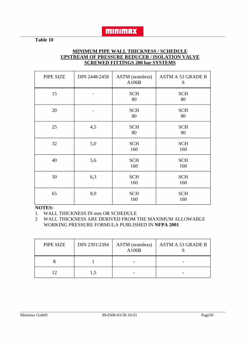
Table 10
MINIMUM PIPE WALL THICKNESS / SCHEDULEUPSTREAM OF PRESSURE REDUCER / ISOLATION VALVE
SCREWED FITTINGS 200 bar SYSTEMS
PIPE SIZE DIN 2448/2458 ASTM (seamless)A106B
ASTM A 53 GRADE BS
15 - SCH80
SCH80
20 - SCH80
SCH80
25 4,5 SCH80
SCH80
32 5,0 SCH160
SCH160
40 5,6 SCH160
SCH160
50 6,3 SCH160
SCH160
65 8,0 SCH160
SCH160
NOTES:1. WALL THICKNESS IN mm OR SCHEDULE2 WALL THICKNESS ARE DERIVED FROM THE MAXIMUM ALLOWABLE
WORKING PRESSURE FORMULA PUBLISHED IN NFPA 2001
PIPE SIZE DIN 2391/2394 ASTM (seamless)A106B
ASTM A 53 GRADE BS
8 1 - -
12 1,5 - -

Minimax GmbH 99-0500-03/30.10.03 Page51
Table 11
MINIMUM PIPE WALL THICKNESS / SCHEDULEDOWNSTREAM OF PRESSURE REDUCER / ISOLATION VALVE
SCREWED FITTINGS
Pipe Size DIN 2448/2458 ASTM (seamless)A106B
ASTM A 53 GRADE BS
15 2,6 SCH40
SCH40
20 2,6 SCH40
SCH40
25 3,2 SCH40
SCH40
32 3,2 SCH40
SCH40
40 3,6 SCH40
SCH40
50 4,0 SCH40
SCH40
65 4,5 SCH40
SCH40
80 4,5 SCH40
SCH40
NOTES:1. WALL THICKNESS IN mm OR SCHEDULE2 WALL THICKNESS ARE DERIVED FROM THE MAXIMUM ALLOWABLE
WORKING PRESSURE FORMULA PUBLISHED IN NFPA 2001
PIPE SIZE DIN 2391/2394 ASTM (seamless)A106B
ASTM A 53 GRADE BS
8 1 - -
12 1,5 - -

Minimax GmbH 99-0500-03/30.10.03 Page52
10.4 Pipe Layout within Protected Area
Argon extinguishing agent is delivered to the protected area through a distribution pipe networkand liberated into the area through discharge nozzles.
When establishing a route for the pipe the system designer should take into consideration thefollowing:
a) It should not, if possible, pass through any other high risk area.
b) It should be direct as possible from cylinder bank to protected area.
c) It should, if possible, be run at one elevation, however even high changes in elevation are possible, but must be checked by hydraulic flow calculation.
d) It should be endeavored to achieve a balanced pipe configuration as this makes the hydraulic flow calculations easier, however unbalanced systems can be accommodated.
e) Ideally it should not pass through an occupied area.
f) Downstream pipework should not exceed a 80 mm nominal bore. If, due to the mass flow of Argon, a larger pipe is needed then two distribution pipe runs are preferred.
g) Where exposed electrical conductors are present and, where practicable, clearances no smaller than those given in Table 12 shall be provided, between the electrical conductors and all parts of the system that may be approached during maintenance. Where these clearance distances cannot be achieved, warning notices shall be provided and a safe system of maintenance work shall be adopted.See also NFPA 2001, Sec. 1-6.2.
h) It should be provided with a dirt trap at the end of each line, after the last nozzle.
The system should be so arranged that all normal operations can be carried out with safety tothe operator.

Minimax GmbH 99-0500-03/30.10.03 Page53
Pipe Isometric Diagram
DRAWING 1

Minimax GmbH 99-0500-03/30.10.03 Page54
10.5 Pipe Size Calculation
The size of pipes shall be determined by the Minimax Argon Flow Calculation Programme,however, pipe sizes can be estimated for quotation purposes by using the following procedure.
From the example Electrical Equipment Room, (see page 33)
discharge ratio Q60/Qg = 0.79
Using the discharge ratio figure (0.79) select the correct graph (graph 5, 6, 7 or 8).
(In this example use graph 7).
This provisional pipe sizing is downstream from the pressure restrictor, therefore the startpressure is approx. 60 bar with the minimum pressure at the nozzle around 45 bar, howeverlower pressures can be tolerated provided the discharge time is maintained.
The Minimax hydraulic computer pipe flow calculations should always be used for final systemdesign.
Determine the equivalent length of pipe run from the furthest nozzle to the restrictor.
From the respective graph read of equivalent length against Q60 flow rate. Curve intersectionwill give pipe diameter. The larger pipe size should be used.
From Drawing 1:
Pipe 1 to 2 = ND 50
Pipe 2 to 3 = ND 25
Pipe 4 to 5 = ND 32
Pipe 5 to 6 = ND 25
Pipe 5 to 8 = ND 25
Pipe 6 to 7 = ND 20
Pipe 8 to 9 = ND 20
Manifold pipe = ND 50
When estimating the equivalent length take the actual pipe run length and add 20% to take intoconsideration elbows and tees. Special attention must be taken when there are valves in thepipework, the following equivalent lengths can be used for estimating purposes.
See Tables 13 and 14.
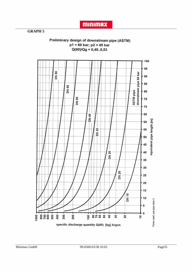
Minimax GmbH 99-0500-03/30.10.03 Page55
GRAPH 5

Minimax GmbH 99-0500-03/30.10.03 Page56
GRAPH 6
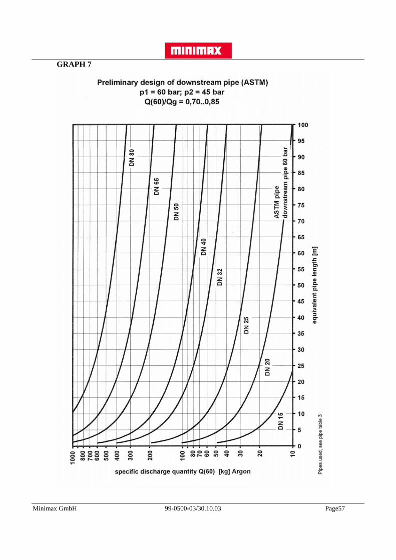
Minimax GmbH 99-0500-03/30.10.03 Page57
GRAPH 7

Minimax GmbH 99-0500-03/30.10.03 Page58
GRAPH 8

Minimax GmbH 99-0500-03/30.10.03 Page59
GRAPH 9

Minimax GmbH 99-0500-03/30.10.03 Page60
GRAPH 10

Minimax GmbH 99-0500-03/30.10.03 Page61
GRAPH 11

Minimax GmbH 99-0500-03/30.10.03 Page62
GRAPH 12
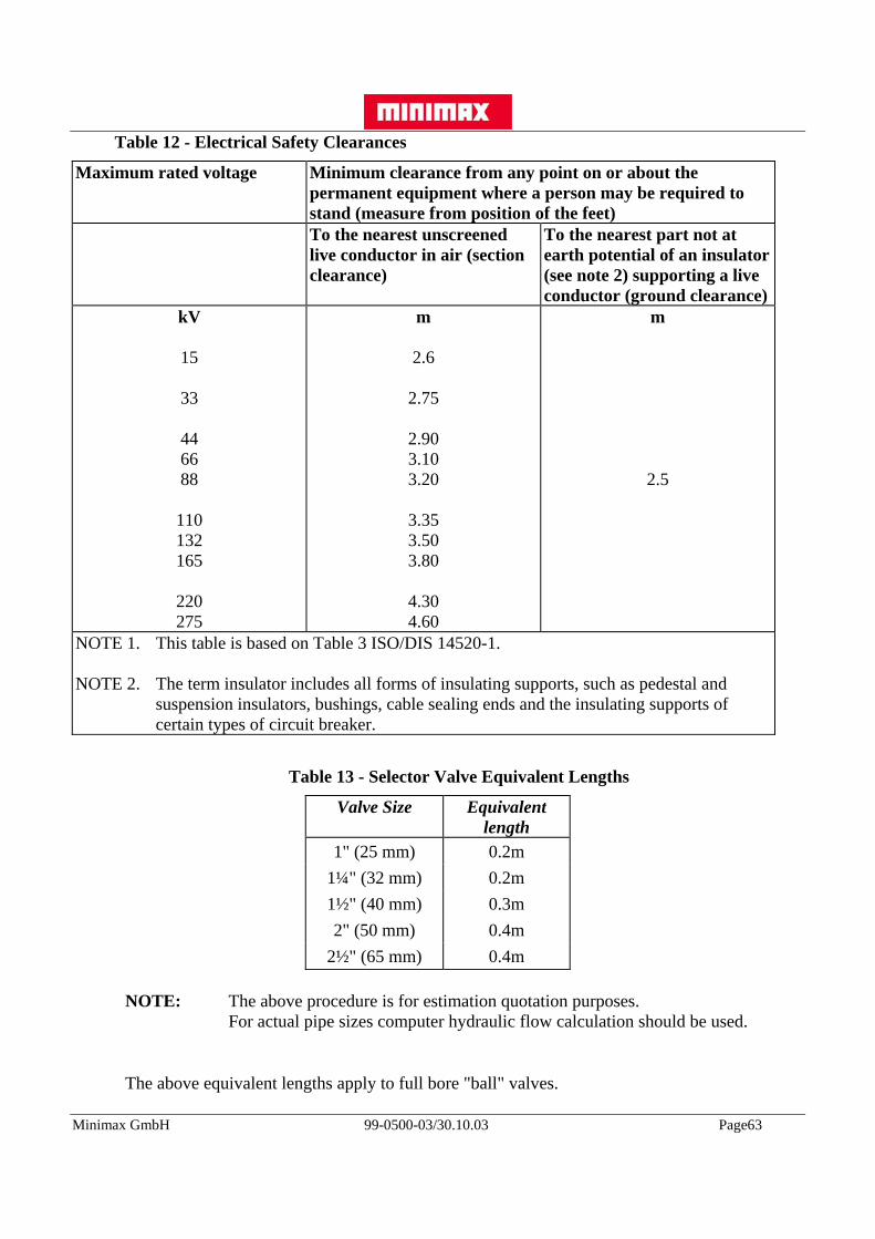
Minimax GmbH 99-0500-03/30.10.03 Page63
Table 12 - Electrical Safety Clearances
Maximum rated voltage Minimum clearance from any point on or about thepermanent equipment where a person may be required tostand (measure from position of the feet)To the nearest unscreenedlive conductor in air (sectionclearance)
To the nearest part not atearth potential of an insulator(see note 2) supporting a liveconductor (ground clearance)
kV
15
33
446688
110132165
220275
m
2.6
2.75
2.903.103.20
3.353.503.80
4.304.60
m
2.5
NOTE 1. This table is based on Table 3 ISO/DIS 14520-1.
NOTE 2. The term insulator includes all forms of insulating supports, such as pedestal and suspension insulators, bushings, cable sealing ends and the insulating supports of certain types of circuit breaker.
Table 13 - Selector Valve Equivalent Lengths
Valve Size Equivalentlength
1" (25 mm) 0.2m1¼" (32 mm) 0.2m1½" (40 mm) 0.3m2" (50 mm) 0.4m
2½" (65 mm) 0.4m
NOTE: The above procedure is for estimation quotation purposes. For actual pipe sizes computer hydraulic flow calculation should be used.
The above equivalent lengths apply to full bore "ball" valves.

Minimax GmbH 99-0500-03/30.10.03 Page64
10.6 Table 14 - Equivalent length of pipe fittings
SCREWED
Diameter 45o 90o T-through T-sideNom mm Elbow Elbow
m m m m3/8 10 0,18 0,40 0,24 0,321/2 15 0,24 0,51 0,30 1,043/4 20 0,30 0,67 0,43 1,371 25 0,40 0,85 0,55 1,74
1.1/4 32 0,52 1,10 0,70 2,291.1/2 40 0,61 1,30 0,32 2,65
2 50 0,79 1,70 1,06 3,412.1/2 65 0,94 2,00 1,25 4,08
3 80 1,20 2,50 1,55 5,06
WELDED
Diameter 45o 90o T-through T-sideNom mm Elbow Elbow
m m m m
3/8 10 0,06 0,15 0,15 0,491/2 15 0,09 0,21 0,21 1,043/4 20 0,12 0,27 0,27 0,851 25 0,15 0,33 0,33 1,10
1.1/4 32 0,21 0,46 0,46 1,401.1/2 40 0,24 0,52 0,52 1,60
2 50 0,30 0,67 0,67 2,102.1/2 65 0,37 0,82 0,82 2,50
3 80 0,46 1,00 1,00 3,11

Minimax GmbH 99-0500-03/30.10.03 Page65
11. REFERENCE DOCUMENTATION
Included in NFPA 2001
Accepted by US EPA
Accepted in UK through HAG
Approved by German Health Authorities
Approved by German VdS
BSI Draft Code of Practice
Included in LPC Report on alternatives to Halon1301
Included in DTI Halon phase out guide

Minimax GmbH 99-0500-03/30.10.03 Page66
12. INSTALLATION OF PIPEWORK
Refer to Installation Manual for the installation and erection of distribution pipework.

Minimax GmbH 99-0500-03/30.10.03 Page67
13. SAMPLE PROBLEM
This section shows the actual printouts of the input and output for the computer program basedon the sample already used in section 8 and 9.
Input project data
Input quantity calculation formula

Minimax GmbH 99-0500-03/30.10.03 Page68
Input room temperature and concentration
Input room geometry

Minimax GmbH 99-0500-03/30.10.03 Page69
Input additional room data
Output quantity calculation
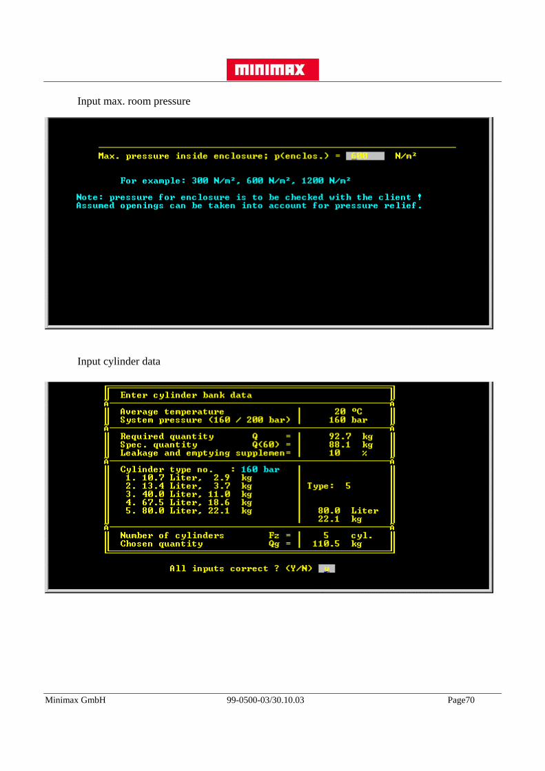
Minimax GmbH 99-0500-03/30.10.03 Page70
Input max. room pressure
Input cylinder data

Minimax GmbH 99-0500-03/30.10.03 Page71
Input pipe work

Minimax GmbH 99-0500-03/30.10.03 Page72
Input nozzle
Output calculated nozzles

Minimax GmbH 99-0500-03/30.10.03 Page73
Output pressure calculation
Output pipe pressure

Minimax GmbH 99-0500-03/30.10.03 Page74
Output pipe pressure
To demonstrate the situation of other design temperatures then 20°C the calculation is extendedto 30°C storage temperature.
Input cylinder bank data at 30°C

Minimax GmbH 99-0500-03/30.10.03 Page75
Output pressure calculation at 30°C
Output pipe pressure at 30°C

Minimax GmbH 99-0500-03/30.10.03 Page76
Output pipe pressure at 30°C
Related Documents