DuPont ™ Minlon ® and Zytel ® nylon resins Design Information – Module II ® DuPont registered trademark The miracles of science ™ is a DuPont trademark 1 3 4 2

Welcome message from author
This document is posted to help you gain knowledge. Please leave a comment to let me know what you think about it! Share it to your friends and learn new things together.
Transcript

DuPont™ Minlon® and Zytel®
nylon resins
Design Information – Module II
® DuPont registered trademarkThe miracles of science™ is a DuPont trademark
1
3
4
2


Table of contents1 General1.1 Introduction1.1 Product overview1.2 Fabrication1.2 Designing with DuPont nylon resins1.3 Compositions1.4 Standards
2 Value engineering2.1 Introduction2.1 Economic incentives for using nylon resins2.1 Cost of producing assemblies by injection moulding2.3 Cost of other processing methods
3 Properties of DuPont nylons3.1 Material properties3.1 Strength and stiffness3.6 Creep, long-term loads and recovery3.12 Impact3.16 Hardness, abrasion resistance, friction and wear
4 Other properties of ZYTEL® and MINLON® resins4.1 Electrical properties4.2 Flammability4.4 Light transmission4.5 Thermal properties
5 Effects of environment on ZYTEL®
5.1 Resistance of ZYTEL® nylon resins to high temperatures
5.3 Resistance of ZYTEL® to hot water and steam5.4 Weathering5.7 Permeability and resistance to chemicals and reagents5.12 Bacteria and fungi: Soil and underground
conditions5.12 Irradiation
6 Dimensional stability6.1 Introduction6.1 Absorption of moisture6.3 Shrinkage and dimensional stability of unreinforced
ZYTEL® resins6.4 Shrinkage and dimensional stability of reinforced
ZYTEL® and MINLON® resins6.4 Combined dimensional effect of mould shrinkage,
stress-relief and moisture absorption6.5 Moisture conditioning6.6 Annealing
7 Quality of fabricated parts – writing of specifications7.1 Introduction7.1 Identification of plastic7.1 Establishment of part quality
8 Regulatory Status8.1 Regulatory compliance
Design information on MINLON® and ZYTEL®


1 – GeneralIntroductionThe invention of nylon by DuPont in the early 30’s, and itsintroduction in 1938, was a major breakthrough in polymerchemistry. No resin has yet been introduced that can begin tomatch the unique combination of properties which has madenylon the most versatile and broadly applied plastic material.Its use as an injection moulding resin to produce a wide vari-ety of engineering plastic parts used in every industry hasgrown, by some estimates, to the existence of more than a half million different parts, and the diversity and growthcontinues as the DuPont nylon resin product line expandsthrough the results of ongoing extensive research and marketdevelopment. Nylon has also found wide and varied uses asan extrusion resin for film, filament and proprietary orientedproducts. Finally, nylon is widely known for its multitude of uses in the textile fibre industry.
The information that follows is intended to help designersand engineers become familiar with the unique character-istics of the DuPont nylon family of ZYTEL® and MINLON®
engineering thermoplastic resins, and how these characteris-tics are affected by environment and stress. With this knowl-edge, the information provided by the Design Handbook –Module I, it is hoped that correct resin selection coupledwith good design practice will result in the development of a successful part in the shortest possible time.
The data contained in this module falls outside the scope ofCAMPUS and should not be used to establish specificationlimits or used alone as the basis for design. Since DuPontcan make no guarantee of results and therefore assumes no liability in connection with the use of this information,confirmation of its validity and suitability should beobtained independently.
Do not use DuPont plastics in medical applications involv-ing permanent implantation in the human body. For othermedical applications, see “DuPont Medical Caution State-ment”, H-50102.
Product overviewBasic DuPont nylon resinsThe “basic” nylon resins include the unmodified nylonhomopolymers and modifications produced by the additionof heat stabilizers, lubricants, ultraviolet screens, nucleatingagents, etc. The majority of resins have molecular weightssuited for injection moulding and some are used for filaments,wire jacketing, film, and extruded shapes including rod, slaband sheet stock.
Many grades of DuPont nylon resin meet European and/ornon-European requirements for food contact applicationsand for potable water uses. Many are rated by Underwriters’Laboratories, Inc. for use in electrical and electronic equip-ment. Many are certifiable to a long list of customer, ISOand ASTM specifications.
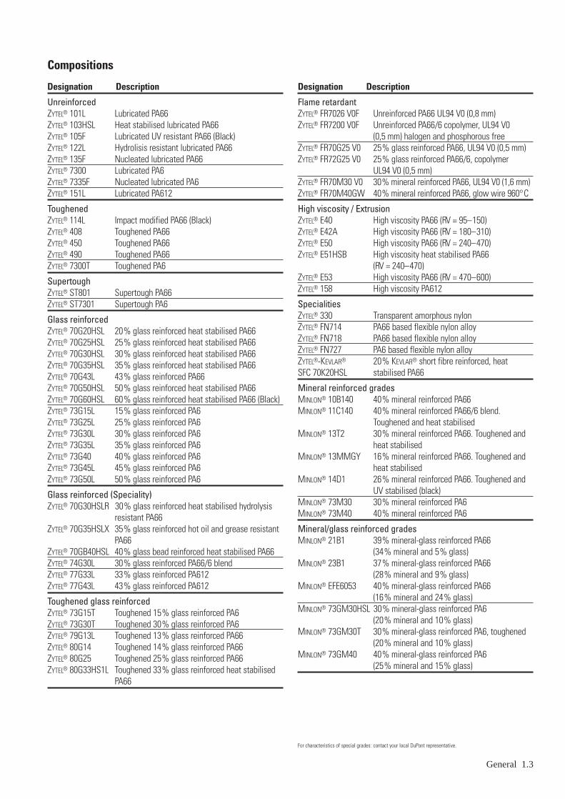
Compositions of DuPont nylon resins and their descriptionare shown in the Table on page 1.3.
66 NylonsThe most important of the nylon resins are ZYTEL® lubricatedversions 101L and 101F. These are 66 nylons made by thepolymerization of hexamethylenediamine and adipic acid,each of which contain six carbon atoms. They possess anoutstanding balance of properties – combining strength,moderate stiffness, high service temperature and a high levelof toughness. They are particularly resistant to repeatedimpact, have low coefficients of friction and excellent resis-tance to abrasion. They resist fuels, lubricants and mostchemicals, but are attacked by phenols, strong acids and oxidizing agents.
The 66 nylons are easily injection moulded. The general pur-pose moulding resins readily fill thin section moulds due tolow melt viscosity. These crystalline polymers set up rapidly,especially the nucleated and lubricated ZYTEL® 135F.
The combination of easy fill and fast set up allows very fastmoulding cycles.
Nylons absorb moisture from the air and 66 nylon equilibratesat about 2,8% water at 50% RH and at about 8,5% at 100%RH. This plasticizes the nylon, lowering its strength andstiffness but increasing its toughness and elongation.Moisture absorption increases dimensions of 66 nylons by0,6% at 50% RH and about 2,6% at 100% RH. The processis reversible, that is, the strength and stiffness increase anddimensions decrease as moisture content decreases. Absorp-tion and desorption are slow processes. For example, it takesabout 125 days for a 1,5 mm thick dry specimen to reachequilibrium moisture content when exposed to 50% relativehumidity.
Nylon resins are not considered primary electrical insulatorsbut their high temperature properties, their toughness andabrasion resistance, and their chemical resistance, combinedwith electrical properties adequate for most power frequen-cies and voltages, have made them the choice for a widevariety of electrical applications.
Toughened DuPont nylon resinsDuPont has developed a series of toughened nylon resinsthat further extends the usefulness of nylon into areas wherevery high toughness is desired. They may be divided intotwo groups, both involving the uniform dispersion of modi-fiers which interfere with the initiation and propagation ofcracks. The effect is seen most dramatically in the Charpyimpact strength, which is raised from about 5 kJ/m2 forZYTEL® 101L (dry-as-moulded, 23°C) to over 20 kJ/m2
for ZYTEL® Toughened nylons.
The first of the series to be introduced was ZYTEL® 408 andrelated resins. These are modified 66 nylons with the Charpyraised to about 25 kJ/m2 and the strength and stiffness low-ered about 25%. They mould very well.
Supertough DuPont nylon resinsThe second series, the “Supertough” nylons resulted from a significant breakthrough in nylon polymer chemistry. The“Supertough” technology has been applied to the 66 nylonmoulding resins, increasing notched Charpy impact values to over 100 kJ/m2, with ductile rather than brittle breaks.
General 1.1

In addition to extremely low notch sensitivity, the super-tough nylons exhibit exceptionally high energy absorptioncharacteristics even in special high speed impact tests. Whilestrength and stiffness are reduced, the outstanding toughnessof these resins commends their consideration whenever theultimate in toughness is needed.
612 nylonsThe 612 nylons, such as ZYTEL® 151L, have lower meltingpoints, strength, and stiffness than 66 nylons. They absorbless water, only about 1,3% at 50% RH and 3,0% at 100%RH, and therefore have better dimensional stability and elec-trical properties. 612 nylons have better chemical resistancethan 66 nylons. As in the case of 66 nylons, heat and weath-er stabilized grades are available.
Glass reinforced DuPont nylon resinsThe glass reinforced DuPont nylon resin families extend the usefulness of nylon to applications requiring an elasticmodulus of up to 11000 MPa and a tensile strength of up to200 MPa. By using various nylon matrices, essential charac-teristics such as dimensional stability, toughness, chemicalresistance, etc., can be maximized to meet the requirementsof a wide range of applications.
Property enhancement is maximized by the uniform disper-sion of specially treated glass fibres into the nylon. Treat-ment of the glass fibres produces a tightly adhering chemicalbond between the nylon and the glass that enhances bothtensile strength and stiffness over a wide range of environ-mental conditions. Glass levels of up to 60% (weight) areavailable in the different matrices. The highest loadings, of course, provide the highest strength and stiffness.
• Nylon 66 matrix based resinsZYTEL® 70G, in different glass loadings has a lubricantadded for improved machine feed and mould release prop-erties. These have the highest strength, stiffness, creepresistance and melting point. They may be pigmented andstabilized against the effects of long term high temperatureexposure (HSL) and hot glycol/water mixtures (HSLR).ZYTEL® 79G is an impact modified resin, which combineshigh stiffness with higher toughness.ZYTEL® 80G is based on a supertough resin for gettinghighest toughness with relatively minor sacrifices instrength and stiffness.
• Nylon 66/6 matrix based resinsZYTEL® 74G30 is a PA66/6 blend, with improved proper-ties related to impact resistance and surface appearancecompared to 70G types
• Nylon 6 matrix based resinsZYTEL® 73G grades are available in glass loadings varyingfrom 15% to 50%. These materials are more sensitive tomoisture than PA66; they therefore generally have a high-er toughness combined with a lower stiffness and strength.The surface appearance of PA6 is excellent. Instead ofglass fibres, several grades are also available with mineralfillers, or mixtures of both.
• Nylon 612 matrix based resinsZYTEL® 77G grades are available with 33 or 43% glass
1.2 General
loadings, giving excellent dimensional stability, also athigher temperatures because of their low moisture absorp-tion.In addition the 77G grades have a better chemical resistance.
MINLON®
MINLON® engineering thermoplastic resins are mineral andmineral/glass reinforced 66 nylons with stiffness and heatdeflecton temperatures approaching those of glass reinforcednylons – but which are lower in cost and exhibit substan-tially less warpage.
The reinforcing materials – either mineral alone or mineral/glass combinations – are chemically bonded to the nylon.Strength and stiffness are increased with some loss of tough-ness and elongation.
MINLON® resins also exhibit greater dimensional stability andcreep resistance than unreinforced nylon.
Various grades of MINLON® have been formulated to meetspecific end use requirements.
Speciality ZYTEL® resins• ZYTEL® FN
ZYTEL® FN flexible nylon alloys are a new family of plas-ticizer-free thermoplastics which offer a unique combina-tion of properties. These flexible resins exhibit high end-use properties, good low temperature toughness and goodchemical resistance. ZYTEL® FN nylon alloys can be pro-cessed on typical thermoplastic equipment. Service tem-peratures range from –40 to 150°C.
• Flame retardent ZYTEL® grades
• Transparent ZYTEL® 330
• ZYTEL®-KEVLAR® SFC
FabricationInjection moulding is the most common method for produc-ing parts of DuPont nylon resins. For specific processingconditions and safe handling, separate literature is available.
ZYTEL® nylons can also be extruded into tubing, rods, slabs,sheeting and film.
Blow moulding can be used for making bottles, reservoirs,and similar parts.
Rods, tubes and other semi-finished extruded shapes ofZYTEL® can be fabricated into small parts by automatic screwmachining. Prototypes and small-run items can be machinedfrom rod or slab stock.
Designing with DuPont nylon resinsMany of the same design considerations apply to ZYTEL® andMINLON® as to metals and other engineering materials. It iscommon practice to use standard engineering equations fordesigning. However, since all engineering materials areaffected to some extent by temperature, moisture and otherenvironmental service conditions, it is necessary to deter-mine the extreme operating conditions and to design a part sothat it will perform satisfactorily under all these conditions.
Designation Description
UnreinforcedZYTEL® 101L Lubricated PA66ZYTEL® 103HSL Heat stabilised lubricated PA66ZYTEL® 105F Lubricated UV resistant PA66 (Black)ZYTEL® 122L Hydrolisis resistant lubricated PA66ZYTEL® 135F Nucleated lubricated PA66ZYTEL® 7300 Lubricated PA6ZYTEL® 7335F Nucleated lubricated PA6ZYTEL® 151L Lubricated PA612
ToughenedZYTEL® 114L Impact modified PA66 (Black)ZYTEL® 408 Toughened PA66ZYTEL® 450 Toughened PA66ZYTEL® 490 Toughened PA66ZYTEL® 7300T Toughened PA6
SupertoughZYTEL® ST801 Supertough PA66ZYTEL® ST7301 Supertough PA6
Glass reinforcedZYTEL® 70G20HSL 20% glass reinforced heat stabilised PA66ZYTEL® 70G25HSL 25% glass reinforced heat stabilised PA66ZYTEL® 70G30HSL 30% glass reinforced heat stabilised PA66ZYTEL® 70G35HSL 35% glass reinforced heat stabilised PA66ZYTEL® 70G43L 43% glass reinforced PA66ZYTEL® 70G50HSL 50% glass reinforced heat stabilised PA66ZYTEL® 70G60HSL 60% glass reinforced heat stabilised PA66 (Black)ZYTEL® 73G15L 15% glass reinforced PA6ZYTEL® 73G25L 25% glass reinforced PA6ZYTEL® 73G30L 30% glass reinforced PA6ZYTEL® 73G35L 35% glass reinforced PA6ZYTEL® 73G40 40% glass reinforced PA6ZYTEL® 73G45L 45% glass reinforced PA6ZYTEL® 73G50L 50% glass reinforced PA6
Glass reinforced (Speciality)ZYTEL® 70G30HSLR 30% glass reinforced heat stabilised hydrolysis
resistant PA66ZYTEL® 70G35HSLX 35% glass reinforced hot oil and grease resistant
PA66ZYTEL® 70GB40HSL 40% glass bead reinforced heat stabilised PA66ZYTEL® 74G30L 30% glass reinforced PA66/6 blendZYTEL® 77G33L 33% glass reinforced PA612ZYTEL® 77G43L 43% glass reinforced PA612
Toughened glass reinforcedZYTEL® 73G15T Toughened 15% glass reinforced PA6ZYTEL® 73G30T Toughened 30% glass reinforced PA6ZYTEL® 79G13L Toughened 13% glass reinforced PA66ZYTEL® 80G14 Toughened 14% glass reinforced PA66ZYTEL® 80G25 Toughened 25% glass reinforced PA66ZYTEL® 80G33HS1L Toughened 33% glass reinforced heat stabilised
PA66
Compositions
Designation Description
Flame retardantZYTEL® FR7026 V0F Unreinforced PA66 UL94 V0 (0,8 mm)ZYTEL® FR7200 V0F Unreinforced PA66/6 copolymer, UL94 V0
(0,5 mm) halogen and phosphorous freeZYTEL® FR70G25 V0 25% glass reinforced PA66, UL94 V0 (0,5 mm)ZYTEL® FR72G25 V0 25% glass reinforced PA66/6, copolymer
UL94 V0 (0,5 mm)ZYTEL® FR70M30 V0 30% mineral reinforced PA66, UL94 V0 (1,6 mm)ZYTEL® FR70M40GW 40% mineral reinforced PA66, glow wire 960°C
High viscosity / ExtrusionZYTEL® E40 High viscosity PA66 (RV = 95–150)ZYTEL® E42A High viscosity PA66 (RV = 180–310)ZYTEL® E50 High viscosity PA66 (RV = 240–470)ZYTEL® E51HSB High viscosity heat stabilised PA66
(RV = 240–470)ZYTEL® E53 High viscosity PA66 (RV = 470–600)ZYTEL® 158 High viscosity PA612
SpecialitiesZYTEL® 330 Transparent amorphous nylonZYTEL® FN714 PA66 based flexible nylon alloyZYTEL® FN718 PA66 based flexible nylon alloyZYTEL® FN727 PA6 based flexible nylon alloyZYTEL®-KEVLAR® 20% KEVLAR® short fibre reinforced, heatSFC 70K20HSL stabilised PA66
Mineral reinforced gradesMINLON® 10B140 40% mineral reinforced PA66MINLON® 11C140 40% mineral reinforced PA66/6 blend.
Toughened and heat stabilisedMINLON® 13T2 30% mineral reinforced PA66. Toughened and
heat stabilisedMINLON® 13MMGY 16% mineral reinforced PA66. Toughened and
heat stabilisedMINLON® 14D1 26% mineral reinforced PA66. Toughened and
UV stabilised (black)MINLON® 73M30 30% mineral reinforced PA6MINLON® 73M40 40% mineral reinforced PA6
Mineral/glass reinforced gradesMINLON® 21B1 39% mineral-glass reinforced PA66
(34% mineral and 5% glass)MINLON® 23B1 37% mineral-glass reinforced PA66
(28% mineral and 9% glass)MINLON® EFE6053 40% mineral-glass reinforced PA66
(16% mineral and 24% glass)MINLON® 73GM30HSL 30% mineral-glass reinforced PA6
(20% mineral and 10% glass)MINLON® 73GM30T 30% mineral-glass reinforced PA6, toughened
(20% mineral and 10% glass)MINLON® 73GM40 40% mineral-glass reinforced PA6
(25% mineral and 15% glass)
General 1.3
For characteristics of special grades: contact your local DuPont representative.

The selection of the best material for any application requiresa knowledge of the properties of all candidate materials andhow they satisfy the requirements of the application.
Much of the engineering data needed in designing withDuPont nylons are given in the following pages and shouldbe helpful to the designer. However, it is always good prac-tice to test prototypes of a proposed design and materialunder realistic conditions before making production commit-ments.
Another responsibility for designers is to keep the impact onthe environment as low as possible. This can be done byoptimal designs, using the right materials, including the pos-sibilites to design for disassembly. By selecting the bestcolourants and other additives, given the knowledge of theimpact on the environment of these additives today, DuPonttries to minimise or avoid any effect on the environment.
For designs, including disassembly possibilities, see DuPont“Design Handbook”, module I: General Design Principles.
1.4 General
StandardsIn principle all new material information, obtained in Europe,is measured according ISO standards. The data in the“Product and properties guide (H-53823 for ZYTEL® and H-53824 for MINLON®)” and CAMPUS are examples.
Because of the long usage of nylons, there is much historicalinformation available, measured according to other stan-dards. Where such information is considered to be useful fordesigners, it is included in this manual; data obtained accord-ing to old or former standards is still considered to be betterthan no data at all.
Users of any of the data in this handbook are, however,strongly recommended to check the validity of the given values for end-use applications.
The technical information in TRG 14 compares ASTM,DIN, BS and ISO standards and test methods.
All ZYTEL® and MINLON® grades are subject to possiblechanges and DuPont can not accept any liability for anydamage caused by the wrong use of properties in designs of plastic parts.

2 – Value engineering
IntroductionZYTEL® and MINLON® nylon resins are converted into usefulparts by a number of processing techniques, with injectionmoulding being the most prevalent. Other methods includeextrusion, machining, nonmelt forming processes and blowmoulding.
There are two important but quite different aspects of the costestimated in considering nylons for a new component, orreplacement of a metal or other material of construction. Thefirst portion of the estimate includes the aggregate of costsfor the tool, material, moulding and postmoulding operations.This is a cost that can be reliably estimated, using standardand accepted procedures.
Less easy to determine, although frequently more important,are the cost savings that may be effected through lower wear,superior performance, or the possibility of combining severalcomponent parts into one structural piece. The wide range of properties available in the DuPont nylon range frequentlypermit novel and imaginative design approaches with savingsin performance and assembly that may even exceed produc-tion costs. These cost savings represent the economic incen-tives for using ZYTEL® or MINLON® and should be consideredseparately from the cost of manufacture or purchase price of the item.
Economic incentives for using DuPont nylonsA few potential savings – or economic incentives – that arefrequently important in cost considerations are given below.
• Elimination or reduction of parts associated with assemb-lies of traditional design. One moulded part may serve thefunction of an assembly of individual parts, as for example,a single moulded part performing the functions of both a gear and a cam.
• Elimination of mechanical finishing operations. In mostcases, plastic parts can be produced fully finished andready for use as ejected from the mould.
• Rapid assembly of parts. The resilience and strength of plastics permit the use of assembly techniques such as snap fitting, press fitting, cold heading, spin welding, sonic welding, angular and linear welding.
• Lower maintenance and service costs. Unreinforced ZYTEL®
has exceptionally good frictional properties and is frequent-ly used in combination with metal and other plastic partswithout additional lubrication.
• Excellent stress crack resistance. ZYTEL® is resistant tostress cracking during cleaning in solvents and detergents.Accordingly, it in TV tuners, switches and power tools.ZYTEL® will remain unharmed by many solvents and chemicals that plasticize or stress crack other plastic materials.
• Longer service life. DuPont nylons have been selected formany demanding applications because of superior repeatedimpact strength and high fatigue endurance level undersevere environmental conditions.
• Lower decorative finishing costs. Most colour effects canbe obtained by using coloured moulding resins. This avoidsthe need for painting.
• Production of colour-coded parts. Colours can be addedduring moulding in order to produce easily identifiablecomponents. Parts can also be readily dyed.
• Avoidance of corrosion. Several problems with metals,including rusting and de-zincification, can be avoided by designing parts in DuPont nylon resins.
• Weight savings where substituted for metal construction.Strong, lightweight parts are used to reduce the weight of the overall assembly. Easier handling and reduced ship-ping costs can be obtained.
Cost of producing assemblies by injection mouldingAs already indicated, the cost of moulded parts (in contrastto potential in-use savings) can be accurately estimated.These costs are broken down into five elements:
Material
For a general guide, the material cost is usually between 30and 50% of the moulded part cost, although this may increaseto 80% for large parts. The cost is partly dependent upon theamount of material purchased, the specific composition usedand colour.
To minimize rework, the size of runners and sprues shouldbe kept to a practical minimum by proper mould design. The reduction of rework material can sometimes be affectedthrough the use of runnerless moulds. In this case, spruesand runners are not removed from the mould with the partsduring the cycle. The runnerless moulding technique, how-ever, is not suitable for all moulds, especially when tempera-ture control within the mould is difficult.
Runners and sprues can be ground up and reused withoutsignificant loss in physical properties, providing care is takento avoid contamination of, or moisture pick up by, the regrind.
Adequate quality control should be applied to parts as theyare produced to improve the overall efficiency of mouldingand to reduce the generation of rework to a minimum
Contribution of tool cost to part cost
Tool costs are largely dependent on the size and complexityof the mould, which in turn is determined by part design andproduction requirements.
Because mould costs can contribute significantly to overallcost, the design of injection moulds for production should beleft to an experienced mould designer. It is advisable to con-sult the mould designer before part design is finalized, sinceeven seemingly insignificant changes in part geometry maygreatly influence the cost of producing the tool and the part.Figure 2.01 illustrates the factors which should be consideredin designing economical injection moulds. Part shape, toler-ances and wall dimensions are all-important factors.
Value engineering 2.1

Cost of the moulding operationThe moulding operation usually constitutes 40–60% of themoulded part cost. Variations in this range depend on thesize of machine employed, cavities in a mould, the extent towhich the machine is utilized in production and part geome-try. Factors associated with the size of the moulding machineare usually in the hands of the moulder. However, the designercan contribute towards reducing the cost of moulding bydesigning components that can be moulded with short cycles.The productivity and, hence, the cost of moulding, dependson four factors: moulding cycle, parts per cycle, productquality and run length.
The moulding cycle depends on many factors. Most impor-tant is the maximum section thickness. Moulding is essen-tially a heat transfer process. Once the mould has been filledwith resin, it is necessary to reduce the temperature of thepiece to a level where it may be removed and yield a part ofthe desired quality. Thicker sections usually require longermoulding cycles. The composition chosen for the part mayalso affect the cycle. Most DuPont nylon resins are semi-crystalline with high transition temperatures, allowing fastmoulding cycles.
The cycle is also dependent on the part specifications. For example, where stringent dimensional tolerances mustbe held, moulding conditions may be needed which wouldlengthen the cycle.
The number of parts per cycle or the number of cavities in a mould determines output, the size of moulding machinerequired and the type of operation used. Usually the number
2.2 Value engineering
Figure 2.01 Guide to factors important in mould design
No. of parts required– annually– over projected tool life
Theoretical optimum numberof cavities
Material flow considerations– max. runner length– cavity to cavity pressure
variations
Moulding machine– clamp force per cavity– platen area– plastifying capacity– injection capacity– max. shot weigth
Part shape
Tolerances
of cavities increases as the required annual volume of partsincreases. There are limitations on this number of cavitiesdepending on part size and complexity, type of mould, runnerlength, dimensional tolerances and machine design. Auto-mated operation, as compared to manual or semi-automatic,will usually result in the design of a tool with fewer cavities.
The number of cavities in a mould may be influenced by theanticipated size of a production order or the annual produc-tion volume. Thus, an economic balance should be reachedbetween the tool cost and the cost of setting up and runningan order.
Cost of post-moulding operationsMost parts made of DuPont nylon resins are moulded as fullyfinished parts. However, sometimes it may be necessary to carry out operations such as conditioning, annealing,machining and decorating. Annealing costs will depend onthe cost of labour and on the annealing medium employed.Costs for machining will depend on the precision and extentof the machining operations involved.
When requirements for moulded parts go beyond the usualdimensional tolerances, and include specifications for suchproperties as relative viscosity or a specified degree of tough-ness, laboratory testing must be done. Costs will vary accord-ing to the tests and sampling required.
Other charges and part costSpecial operating, handling or packaging of moulded partsor short moulding runs may cause supplementary charges.
Type of mould 2 or 3 plate?Cam actions, core pullers,inserts
Design and cost of production mould

Cost of other processing methods
The injection moulding process has been discussed in somedetail. However, ZYTEL® non reinforced nylons also may beconverted into useful objects by extrusion, by thermoform-ing of extruded and cast sheet, blow moulding, powder sinter-ing and various nonmelt techniques.
• Extrusion. Extrusion is a continuous process used in theproduction of sheet, rods, tubes or shapes from resin. Withextrusion, it is possible to produce these items economical-ly in large volume with a low tooling cost.
• Thermoforming. Thermoforming is a process for the manu-facture of shapes from sheet. Material costs for makingparts from sheet will normally be higher than those forinjection moulding. However, considerably lower toolingcosts can give this process an economic advantage overmoulding where production volume is low.
• Blow moulding. In the blow moulding process a “parison”is produced, by extrusion or injection moulding, from whichthe finished article is blown. Blow moulding allows theproduction items such as bottles and tanks economically in large volumes with low tooling cost.
Value engineering 2.3


Properties of DuPont nylons 3.1
Material properties
IntroductionIt is important for the designer to realize, that DuPont nylonresins have strength and stiffness properties considerablydifferent from some of the older engineering materials, par-ticularly most metals. In general the strength and stiffnessproperties of nylon resins are more sensitive to environmentalchanges of moisture and temperature.
However with adequate knowledge of the effects of the envi-ronment the designer is better able to get the best out of thepotentials of DuPont nylon resins.
This handbook contains properties of DuPont nylon resinsshown in tables and graphs. Standard graphical informationabout general grades, like stress-strain curves, viscosity ver-sus shear rate, are included in CAMPUS (version 2.4 andsubsequent issues) and not repeated in this handbook; seealso Table 3.01.
For a copy of the DuPont materials in the CAMPUS data-base, contact your DuPont representative.
Later on in this handbook several references are made to“ZYTEL® 101”. This implies the generic name for the grades:ZYTEL® 101L, ZYTEL® 101F and ZYTEL® 103HSL all of whichhave similar values for the applicable properties.
In those cases where graphs do not include a reference to thesource of the data, they are copied from the original versionof this handbook: “The DuPont ZYTEL® Nylon Resin DesignHandbook”.
Strength and stiffnessWhen pulling a moulded test bar in a tensile test machine,one registres the pulling force versus the elongation. Divid-ing the force by the original cross sectional area of the testbar and the elongation by the original length, one obtains thestress-strain curve.
From the stress strain curve, several interesting materialparameters can be derived:
• (tensile) strength, the stress at which the test bar breaks
• yield strength, the first maximum in the stress-strain curve(only applicable to high toughness materials)
• modulus of elasticity, slope of curve at 0% strain, (E = 100 σ/ε; ε in%).The tensile modulus is obtained with tensile test bars, a flexural modulus is derived using bending tests.
• elongation-at-break, the strain at which the test bar breaks.
Stress-strain behaviour of ZYTEL® and MINLON® resinsHumidity and temperature are two environmental factorsimportant for nylon resins. The effects of moisture onZYTEL® 101 are shown in Figure 3.01, in which completestress-strain curves are shown for dry as moulded and alsofor 50 and 100% relative humidities. Increasing humidityresults in greater flexibility (lower modulus of elasticity) andtoughness but also in lower yield and tensile strengths.
3 – Properties of DuPont nylons
Higher temperatures result in lower tensile and yield values.For stress-strain curves of ZYTEL® 77G43L, see Figure 3.02.More stress-strain curves of ZYTEL® and MINLON® resins(details) are included in CAMPUS, as indicated in Table 3.01.
Tension and compressionIn some calculations, it is important for the designer to knowthe stress-strain curves in both tension and compression.Figure 3.03 shows these data for ZYTEL® 101 nylon resin at 23°C.
Figure 3.01 Tensile stress-strain data for ZYTEL® 101 (PA66) at 23°C at various moisture contents
Figure 3.02 Stress vs. strain at two temperatures and humidities, ZYTEL® 77G43L (PA612, 43% GR)
60
Tens
ile s
tres
s (M
Pa)
20
100Strain (%)
0 50 150 200 250 300
40
80Dry as moulded0,2% moisture content
50% RH(2,8% moisture content)
100% RH(8,5% moisture content)
23°C, dry as moulded
Strain (%)
Stre
ss (M
Pa)
20
100
220
0 4 12 168
40
60
80
120
140
160
180
200
240
23°C, 50% RH
150°C, dry as moulded
0
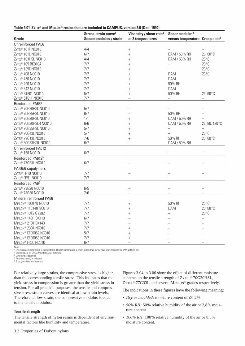
Table 3.01 ZYTEL® and MINLON® resins that are included in CAMPUS, version 3.0 (Dec. 1994)Stress-strain curve1 Viscosity / shear rate2 Shear modulus3
Grade Secant modulus / strain at 3 temperatures versus temperature Creep data4
Unreinforced PA66ZYTEL® 101F NC010 4/4 + – –ZYTEL® 101L NC010 6/7 + DAM / 50% RH 23, 60°CZYTEL® 103HSL NC010 4/4 + DAM / 50% RH 23°CZYTEL® 105 BK010A 7/7 + – 23°CZYTEL® 135F NC010 7/7 + – 23°CZYTEL® 408 NC010 7/7 + DAM 23°CZYTEL® 450 NC010 7/7 + DAM –ZYTEL® 490 NC010 7/7 + 50% RH –ZYTEL® E42 NC010 7/7 + DAM –ZYTEL® ST801 NC010 5/7 + 50% RH 23, 60°CZYTEL® ST811 NC010 7/7 – – –Reinforced PA665
ZYTEL® 70G20HSL NC010 5/7 – – –ZYTEL® 70G25HSL NC010 6/7 – 50% RH –ZYTEL® 70G30HSL NC010 1/1 + DAM / 50% RH –ZYTEL® 70G30HSLR NC010 6/6 + DAM / 50% RH 23, 80, 120°CZYTEL® 70G35HSL NC010 5/7 + – –ZYTEL® 70G43L NC010 5/7 + – 23°CZYTEL® 79G13L NC010 7/6 + 50% RH 23, 80°CZYTEL® 80G33HSIL NC010 6/7 – DAM / 50% RH –Unreinforced PA612ZYTEL® 158 NC010 6/7 – – –Reinforced PA6125
ZYTEL® 77G33L NC010 6/7 – – –PA 66/6 copolymersZYTEL® FR10 NC010 7/7 – – –ZYTEL® FR51 NC010 7/7 – – –Reinforced PA65
ZYTEL® 73G20 NC010 6/5 – – –ZYTEL® 73G30 NC010 7/6 – – –Mineral reinforced PA66MINLON® 10B140 NC010 7/7 + 50% RH 23°CMINLON® 11C140 NC010 7/7 + DAM 23, 80°CMINLON® 13T2 GY282 7/7 + – 23°CMINLON® 14D1 BK113 6/7 – – –MINLON® 21B1 BK143 7/7 – – –MINLON® 23B1 NC010 7/7 + – –MINLON® EFE6052 NC010 5/7 + – –MINLON® EFE6053 NC010 7/7 + – –MINLON® FR60 NC010 6/7 – – –Notes:1 The indicated number refers to the number of different temperatures at which stress-strain curves have been measured for DAM and 50% RH.2 Viscosities are for Dry-As-Moulded (DAM) materials.3 Conditions as specified.4 At temperature(s) as indicated.5 Short glass-fibre reinforcement.
3.2 Properties of DuPont nylons
For relatively large strains, the compressive stress is higherthan the corresponding tensile stress. This indicates that theyield stress in compression is greater than the yield stress intension. For all practical purposes, the tensile and compres-sive stress-strain curves are identical at low strain levels.Therefore, at low strain, the compressive modulus is equal to the tensile modulus.
Tensile strengthThe tensile strength of nylon resins is dependent of environ-mental factors like humidity and temperature.
Figures 3.04 to 3.06 show the effect of different moisturecontents on the tensile strength of ZYTEL® 70G30HSL,ZYTEL® 77G33L and several MINLON® grades respectively.
The indications in these figures have the following meaning:
• Dry as moulded: moisture content of ≤0,2%.
• 50% RH: 50% relative humidity of the air or 2,8% mois-ture content.
• 100% RH: 100% relative humidity of the air or 8,5%moisture content.

The effect of the temperature on the tensile strength is shownfor ZYTEL® 70G30HSL, ZYTEL® 73G30 and ZYTEL® 77G33Lin Figures 3.07–3.08.
Figure 3.09 shows this for several MINLON® grades.
For glass-fibre reinforced nylon, the fibre content also has abig influence on the tensile strength, which is demonstratedin Figure 3.10.
100
75
50
25
0
–25
–50
–75
–100
Tension
Strain (%)
Stre
ss (M
Pa)
12
A
840–4–8–12
B
Compression
B
A
A: Dry as mouldedB: 50% RH
Relative humidity (%)
Tens
ile s
tren
gth
(MPa
)
20
100
220
0 20 10060
40
60
80
120
140
160
180
200
240
ZYTEL® 70G30HSL
040 80
ZYTEL® 77G33L
ZYTEL® 77G33L
ZYTEL® 70G30HSL
23°C
80°C
Figure 3.03 Stress-strain curves in tension and compression of ZYTEL® 101(PA66), 23°C
Figure 3.04 Tensile strength vs. humidity. ZYTEL® 70G30HSL (PA66), ZYTEL® 77G33L (PA612)
Properties of DuPont nylons 3.3
Relative humidity (%)
Tens
ile s
tren
gth
(MPa
)
50
0 40 10020
MINLON® 10B140MINLON® 11C140
60 80
100 MINLON® 23B1
Relative humidity (%)
Tens
ile s
tren
gth
(MPa
)
25
0 40 10020 60 80
50
MINLON® 11C140
MINLON® 23B1
MINLON® 10B140
Temperature (°C)
Tens
ile s
tren
gth
(MPa
)
20
120
– 50 0 100
180
220
015050
100% RH40
60
80
100
140
160
200
50% RH
Dry as moulded
Figure 3.05 Tensile strength of MINLON® vs. humidity at 23°C
Figure 3.06 Tensile strength of MINLON® vs. humidity at 90°C
Figure 3.07 Tensile strength vs. temperature and moisture content of ZYTEL® 70G30HSL, cross-head speed 5 mm/min

ZYTEL® 70G30HSL
Temperature (°C)
Tens
ile s
tren
gth
(MPa
)
50
150
– 40 0 80
100
200
300
0
250
16012040
ZYTEL® 73G30
ZYTEL® 77G33L
Temperature (°C)
Tens
ile s
tren
gth
(MPa
)
25
–40 –20 0
100
50
75
125
MINLON® 10B140MINLON® 11C140
MINLON® 23B1
20 40 60 80 100 120 140 160
Dry as moulded
Glass content (%)
Tens
ile s
tren
gth
(MPa
)
0 10 500
6020 30 40
50% RH
100% HR
40
80
120
160
200
240
Figure 3.08 Tensile strength vs. temperature of ZYTEL® 70G30HSL, 73G30, 77G33L (dry-as-moulded)
Figure 3.09 Tensile strength of MINLON® vs. temperature, dry-as-moulded
Figure 3.10 Tensile strength vs. glass content, 23°C. ZYTEL® 70G(XX)HSL (in flow direction)
3.4 Properties of DuPont nylons
Shear strengthWhen a plastic part is subjected mainly to shear forces, it is not the tensile strength which is decisive for the allowableload, but the shear strength.
According the Von Mises equivalent stress theory the follow-ing statement can be used:Allowable shear stress = allowable tensile stress / √3.
Yield strengthFor tough materials yield stress is of greater importance indesign than is tensile strength… once a part undergoes per-manent deformation, failure is usually implied. The effectsof temperature and humidity on the yield point of ZYTEL® 101are shown in Figure 3.11 and of ZYTEL® 158 in Figure 3.12.
The rate at which a plastic is stressed may have a significanteffect upon its strength.
60
Yiel
d po
int (
MPa
)
100
80
40
20100 12060 8040200–20– 40
Temperature (°C)
Dry as moulded
50% RH
100% RH
60
Yiel
d st
ress
(MPa
)
100
80
40
200– 40
Temperature (°C)
Dry as moulded50% RH
40 80
Figure 3.11 Yield point of ZYTEL® 101 (PA66) vs. temperature and moisturecontent
Figure 3.12 Yield point of ZYTEL® 158 (PA612) vs. temperature and moisturecontent

Properties of DuPont nylons 3.5
Figure 3.13 shows that the yield strength of ZYTEL® 101increases with the rate of loading.
Modulus of elasticity / flexural modulusThe value of the modulus of elasticity under specificenvironmental conditions such as moisture and temperatureare shown in Figure 3.14 for ZYTEL® 101, in Figure 3.15 forZYTEL® 158 and in Figure 3.16 for ZYTEL® 408. This infor-mation may be used to calculate initial deflection under load.For deformation with time under load, reference should bemade to Creep and Stress Relaxation.
For the flexural modulus of ZYTEL® ST801 as function oftemperature, see Figure 3.17. For several MINLON® grades,this property is shown in Figure 3.18.
Picture 3.19 shows the flexural modulus at 1% strain (= apparent modulus) as function of temperature for ZYTEL®
70G30 and ZYTEL® 70G43.
60
Yiel
d st
ress
(MPa
) 80
40
20
0Strain rate (cm/min.)
102 103 104 105
100
120
A 130°C
B 130°C
A 200°C
B 200°C
A 23°C
B 23°C
A: Dry as moulded B: 50% RH
2000
Flex
ural
mod
ulus
(MPa
)
1000
40Temperature (°C)
Dry as moulded
50% RH
– 40 0 80 120 160 200 240
3000
100% RH
Figure 3.13 Yield stress data for ZYTEL® 101, dry as moulded and 50% RH vs. strain rate and temperature
Figure 3.14 Flexural modulus of ZYTEL® 101 (PA66) vs. temperature at variousmoisture contents
2000
Flex
ural
mod
ulus
(MPa
)
1000
40Temperature (°C)
– 40 0 80 120 160 200
3000
50% RH
Dry as moulded (0,2%
)
2000
Flex
ural
mod
ulus
(MPa
)
1000
40Temperature (°C)
– 40 0 80 120 160 200
3000
Dry as moulded (0,2%
)50% RH
2000
Flex
ural
mod
ulus
(MPa
)
1000
500
Temperature (°C)– 60 – 40
1500
2500
3000
– 20 0 20 40 60 80 100 120
3500
4000
0
Dry as moulded(0,2% moisture content)
50% RH(2,6% moisture content)
Figure 3.17 Flexural modulus of ZYTEL® ST801 (PA66, supertough) vs. temperature at two moisture contents
Figure 3.15 Flexural modulus of ZYTEL® 158 (PA612) vs. temperature at two moisture contents
Figure 3.16 Flexural modulus of ZYTEL® 408 (PA66, toughened) vs. temperatureat two moisture contents

3.6 Properties of DuPont nylons
Flex
ural
mod
ulus
(MPa
)
1000
700080009000
1000011000
20003000400050006000
25 50 75 100 125Temperature (°C)
MINLON® 23B1MINLON® 10B140
MINLON® EFE6053 BK319MINLON® 73GM30
MINLON® 11C140
10040200
Flex
ural
mod
ulus
(MPa
)
Relative humidity (%)
2000
4000
6000
8000ZYTEL® 70G30HSL
10000
060 80
ZYTEL® 77G33L
Figure 3.18 Flexural modulus of MINLON® vs. temperature, dry-as-moulded
Figure 3.20 Flexural modulus vs. humidity at 23°CZYTEL® 70G30HSL (PA66, 30% GR)ZYTEL® 77G33L (PA612, 33% GR)
Temperature (°C)
Flex
ural
mod
ulus
(MPa
) at 1
% s
trai
n
0
2500
5000
7500
10000
12500
15000
17500
0–25 5025 10075 150125
ZYTEL® 70G43, 50%RH
ZYTEL® 70G30, 50%RH
ZYTEL® 70G43, DAM
ZYTEL® 70G30, DAM
Figure 3.19 Flexural modulus at 1% strain (= apparent modulus) vs. temperaturefor ZYTEL® 70G30 and ZYTEL® 70G43
The effect of humidity on the flexural modulus of ZYTEL®
70G30HSL, 77G33L and several MINLON® grades is shown in Figures 3.20 and 3.21.
Likewise for the tensile strength, the amount of glass in aglass fibre reinforced nylon is very important for the flexuralmodulus, as demonstrated by Figure 3.22.
Poisson ratioThough the Poisson ratio is not very important in the design ofplastic parts, it is a required input for finite element analyses.
The following values can be used for ZYTEL® and MINLON®
resins:
500 <E <1500; υ = 0,401500 <E <10000; υ = 0,35E = modulus of elasticity in MPa
Creep, long-term loads and recoveryLong-term loads in airAs with all plastics, the long-term behaviour of ZYTEL® underload is characterized by the phenomenon usually called creep.Upon loading, a plastic part shows an initial deformation or strain roughly predicted by its modulus of elasticity. Thisis followed by a slow but steady increase in strain with timeuntil eventual rupture. This increase in strain with time isreferred to as creep.
The creep rate of ZYTEL® will vary markedly with composi-tion, ambient temperature, stress level and moisture content.Consequently, design must be based on a consideration of estimated creep behaviour of the particular resin under the environmental conditions expected.
Creep data are presented as the sum of the initial strain plusthe incremental strain with time. In the past, this has beentermed the sum of elastic deformation and plastic flow. No effort is made to separate the effects of initial strain and creep strain.
Creep data may be graphed in a variety of ways. A usefulform is isochronous (equal time) stress vs. strain, for a select-ed number of time periods. The apparent (creep) moduluscan be derived from these curves from the strain data at anypoint in time.
1000
Flex
ural
mod
ulus
(MPa
)
Relative humidity (%)
1000
7000
50
2000
3000
4000
5000
6000
10 20 30 40 60 70 80 90
MINLON® 11C140
MINLON® 23B1MINLON® 10B140
Figure 3.21 Flexural modulus of MINLON® vs. humidity at 23°C

60100
Flex
ural
mod
ulus
(MPa
)
Glass content (%)
2000
4000
6000
8000
10000
020 30 40 50
12000
14000
50 % RH
Dry
100 % RH
Figure 3.22 Flexural modulus vs. glass content, 23°C. ZYTEL® 70G % HSL (in flow direction)
Table 3.02 Materials for which creep information is given in this Figure Material Temperature °C Relativ3.24 ZYTEL® 101F NC010 125 Dry3.25 ZYTEL® 103HSL 125 Dry3.26 ZYTEL® 151L 23 503.27 ZYTEL® 158 23 503.28 ZYTEL® 158 60 503.29 ZYTEL® 153HSL 125 Dry3.30 ZYTEL® 408HSL 23 503.31 ZYTEL® 408HSL 125 Dry3.32 ZYTEL® 70G43L 60 503.33 ZYTEL® 70G43L 125 Dry3.34 ZYTEL® 70G60HSL 23 503.35 ZYTEL® 70G60HSL 80 Dry3.36 ZYTEL® 70G60HSL 120 Dry3.37 ZYTEL® 79G13L 125 Dry3.38 ZYTEL® 80G14 23 503.39 ZYTEL® 80G14 125 Dry3.40 ZYTEL® 77G43 23 503.41 ZYTEL® 77G43 125 Dry3.42 MINLON® 11C140 125 Dry3.43 MINLON® 23B1 23 503.44 MINLON® 23B1 125 Dry
8,0
Stra
in (%
) 6,0
2,0
Time (h)
010510410310210110010–2 10–1
4,0
10,0
20 MPa
10 MPa
8,0
Stra
in (%
) 6,0
2,0
Time (h)
010510410310210110010–2 10–1
4,0
10,0
20 MPa
10 MPa
Figure 3.24 Creep in flexure for ZYTEL® 101F, at different stress levels,60°C and 50% RH
Figure 3.23 Creep in flexure for ZYTEL® 101F, at different stress levels,23°C and 50% RH
Properties of DuPont nylons 3.7
handbook (for other creep data, see Table 3.01/CAMPUSe humidity % Creep presentations Reference
Creep in flexure EMPA testsIsochronous stress vs. strainIsochronous stress vs. strainIsochronous stress vs. strainIsochronous stress vs. strainIsochronous stress vs. strainIsochronous stress vs. strainIsochronous stress vs. strainIsochronous stress vs. strainIsochronous stress vs. strainCreep in flexureCreep in flexureCreep in flexureCreep in flexure EMPA testsCreep in flexure EMPA testsCreep in flexure EMPA testsIsochronous stress vs. strainIsochronous stress vs. strainCreep in flexure EMPA testsCreep in flexureCreep in flexure

3.8 Properties of DuPont nylons
8,0
Stra
in (%
) 6,0
2,0
Time (h)
010510410310210110010–2 10–1
4,0
10,0
5 MPa
10 MPa
15 MPa
20 MPa
7,5
Stre
ss (M
Pa)
5
2,5
1Strain (%)
2 43
0,1 h 1 h 100 h 2000 h
0
0
Stre
ss (M
Pa)
1,0Strain (%)
2
4
6
8
10
12
14
16
18
0,50 2,52,01,5 4,03,53,0
0,1 h
1 h5000 h
100 h
Figure 3.25 Creep in flexure for ZYTEL® 101F, at different stress levels, 125°C,dry as moulded
Figure 3.26 Isochronous stress vs. strain in flexure of ZYTEL® 103HSL at 125°C,and dry as moulded
Figure 3.27 Isochronous stress vs. strain in flexure of ZYTEL® 151L, 23°C, 50% RH
15
Stre
ss (M
Pa)
10
5
1Strain (%)
2 43
0,1 h 1 h
100 h 5000 h
0
15
Stre
ss (M
Pa)
10
5
1Strain (%)
2 43
0,1 h 1 h
100 h
0
7,5
Stre
ss (M
Pa)
5
2,5
1Strain (%)
2 43
0,1 h 1 h 10 h
0
Figure 3.28 Isochronous stress vs. strain in flexure of ZYTEL® 158 at 23°C and 50% RH
Figure 3.29 Isochronous stress vs. strain in flexure of ZYTEL® 158 at 60°C and 50% RH
Figure 3.30 Isochronous stress vs. strain in flexure of ZYTEL® 153HSL at 125°C,and dry as moulded

Properties of DuPont nylons 3.9
4
Stre
ss (M
Pa)
0Strain (%)
1,00,5 1,5 2,0 4,02,5 4,53,0 3,50
2
10
6
8
16
12
14
18
0,1 h 1 h 5000 h100 h
0
Stre
ss (M
Pa)
Strain (%)
2
6
4
8
10
12
14
1,00,5 1,5 2,0 2,5 3,0 3,5 4,0
0,1 h 1 h 100 h
0
25
Stre
ss (M
Pa)
10
5
Strain (%)
00,80,60,50,40,30,20 0,1
20
15
30
35
0,1 h 1 h
5000 h100 h
0,7
Figure 3.31 Isochronous stress vs. strain in flexure of ZYTEL® 408HSL, 23°C,50% RH
Figure 3.32 Isochronous stress vs. strain in flexure of ZYTEL® 408HSL, 125°C, dry
Figure 3.33 Isochronous stress vs. strain ZYTEL® 70G43L at 60°C, 50% RH
20
Stre
ss (M
Pa)
10
5
Strain (%)
00,80,60,50,40,30,20 0,1
15
25
30
0,7
0,1 h 1 h
5000 h
100 h
Stra
in (%
)
0,5
0,4
0,3
0,2
0,1
Time (h)
00,1
30 MPa
1 10 100 1000 10000
25 MPa
Stra
in (%
)
Time (h)0,1 100 1000
25 MPa
1 10
0,5
0,4
0,3
0,2
0,1
0
30 MPa
Figure 3.35 Creep in flexure of ZYTEL® 70G60HSL (PA66, 60% GR) at 25 and 30 MPa, 23°C, 50% RH
Figure 3.36 Creep in flexure of ZYTEL® 70G60HSL (PA66, 60% GR) at 25 and 30 MPa, 80°C, dry as moulded
Figure 3.34 Isochronous stress vs. strain ZYTEL® 70G43L at 125°C, dry

Stra
in (%
)
Time (h)0,01 0,1 1 10 100 100
25 MPa
30 MPa
0,5
0,4
0,3
0,2
0,1
0
4,0
Stra
in (%
) 3,0
1,0
Time (h)
010510410310210110010–2 10–1
2,0
5,0
5 MPa
10 MPa
15 MPa
20 MPa
4,0
Stra
in (%
) 3,0
1,0
Time (h)
010510410310210110010–2 10–1
2,0
5,0
5 MPa
10 MPa
15 MPa
20 MPa
Figure 3.39 Creep in flexure of ZYTEL® 80G14 (PA66 toughened, 14% GR) at different stress levels, 23°C, 50% RH
Figure 3.37 Creep in flexure of ZYTEL® 70G60HSL (PA66, 60% GR) at 25 and 30 MPa, 120°C, dry as moulded
Figure 3.38 Creep in flexure of ZYTEL® 79G13L at different stress levels,125°C, dry as moulded
3.10 Properties of DuPont nylons
4,0
Stra
in (%
) 3,0
1,0
Time (h)
010510410310210110010–2 10–1
2,0
5,0
5 MPa
10 MPa
15 MPa
20 MPa
30
Stre
ss (M
Pa)
10
Strain (%)
00,60,50,40,30,20 0,1
20
40
0,1 h 1 h 100 h
1000 h
Figure 3.40 Creep in flexure of ZYTEL® 80G14 (PA66, toughened, 14% GR) at different stress levels, 125°C, dry as moulded
Figure 3.41 Isochronous stress vs. strain in flexure of ZYTEL® 77G43 (PA612),125°C, dry
4,0
Stra
in (%
) 3,0
1,0
Time (h)
010510410310210110010–2 10–1
2,0
5,0
5 MPa
10 MPa
15 MPa
20 MPa
Figure 3.42 Creep in flexure of MINLON® 11C140 at different stress levels,125°C, dry as moulded

Another form is shown in graphs presenting the amount oftotal strain vs. time for a selected number of stresses. This is a clearer representation of experiments and fits better withthe needs of computer aided analyses.
From the Isochronous stress vs. strain curves, the “Creep in flexure” for a given stress level (see Figures 3.23–3.25),can be constructed vice versa, if desired.
All creep data presented in this Section were determined ontest specimens 12,7 mm wide by 3,2 mm thick, freely sup-ported at the ends on a 100 mm span and loaded in flexure at the centre of the span.
Creep data at selected conditions of temperature and relativehumidity equilibrium for a number of ZYTEL® compositionsare shown in the Figures 3.23–3.44
For glass-fibre reinforced nylon 66 grades, ZYTEL® 70Gxx, it has shown to be possible to express the total strain as:
εtotal = εelastic + εcreep = σ + 0,1 σ t0,2 = σ (1 + 0,1 t0,2)E E E
with: σ = stress (MPa); E = modulus of elasticity at given temperature (MPa);t = time (h).
For other nylon family grades similar formulae can be derived.
Stra
in (%
)
0,25
Time (h)
0,05100001000100101
0,100,100,150,20
0,300,350,400,450,50
Stra
in (%
)
Time (h)
0,2
100001000100101
0,3
0,4
0,5
0,6
Figure 3.43 Creep in flexure of MINLON® 23B1 at 6,9 MPa, 23°C, 50% RH
Figure 3.44 Creep in flexure of MINLON® 23B1 at 6,9 MPa, 125°C, dry as moulded
Creep (Apparent) ModulusIn parts with a uniform stress distribution, the deformationscan be computed using the creep modulus. This property canbe obtained from the isochronous creep curves, using theright time / stress / temperature, with:
Ecreep = 100 σ/εtotal, (εtotal in%)
Long-term loads in waterData for hoop stress vs. time to failure for pipes of ZYTEL® 42and 101 nylon resin exposed to internal water pressure inwater baths at indicated temperatures are shown in Figures3.45 and 3.46. It is suggested these data be used in conjunc-tion with the creep curves to formulate designs for itemssubject to internal pressure. The design should be thoroughlyevaluated by realistic testing.
Recovery from cyclic loading in airFigures 3.47–3.48 show the behaviour of ZYTEL® 101 undercyclic loads at room temperature. Upon removal of stress,there is an immediate elastic recovery followed by a timedependent recovery. Time under load is an important factorinfluencing extent of recovery when stresses are well belowthe yield stress. In general, the amount of recovery afterremoval of static loads will depend on the duration of stress,the stress level, temperature, nature of the environment, thetime allowed for recovery and most important, the shape ofthe tested sample.
Properties of DuPont nylons 3.11
Hoo
p st
ress
(MPa
)
Time to failure (h)10 102 103 104 105
20
30
10
23°C
45°C
60°C
1
Hoo
p st
ress
(MPa
)
Time to failure (h)10 102 103 104 105
20
30
10
1
At 50% RH
At saturation
1 year
Figure 3.45 Hoop stress vs. time to failure for ZYTEL® 42 at differenttemperatures. Pipe saturated with 8,5% moisture (100% RH)
Figure 3.46 Hoop stress vs. time to failure, ZYTEL® 101 at 50% RH and saturated, 66°C

3.12 Properties of DuPont nylons
Stress relaxation in airFigure 3.49 shows the long-term decay of stress due to creepin a beam subjected to a fixed deflection. This behaviourmust be considered in applications such as preloaded springs,self-tapping screws and press fits.
Time (h)150
2
3
1
0
Def
lect
ion
(mm
)
Average of 8 specimens tested
50 100
Time (h)150
2
3
1
Def
lect
ion
(mm
)
50 100
Average of 8 specimens tested
4
5
% o
f ini
tial s
tres
s re
tain
ed
Time (h)101
20
40
60
100
10210–1
80
103 105 106
Figure 3.49 Stress relaxation in deflected cantilever beams of ZYTEL® 101 nylonresins. Outer fibre strain 2%; initial stress (0,1 hour after loading),13,8 MPa
Figure 3.47 Cyclic loading and recovery of ZYTEL® 101, short term, 6,9 MPa,23°C. Test bar 95 × 12,7 × 3,2 mm; loaded at one end
Figure 3.48 Cyclic loading and recovery of ZYTEL® 101, short term, 13,8 MPa,23°C. Test bar 89 × 12,7 × 3,2 mm; loaded at one end
ImpactImpact resistance – single blowImpact resistance, or the ability of a part to absorb a blow, isdifficult to predict in a moulded part because shape has amajor effect on performance. Consequently, good design isimportant in helping parts resist impact, especially in termsof applying generous radii for all sharp corners. The energyof an impact must be absorbed within the part. Hence,designing flexibility into the part greatly improves resistanceto impact. Thin-walled flexible pieces like round coil formsare difficult to break on impact. On the other hand, rigid corners are less tough because they absorb less impact energy.
A variety of test procedures is used to measure the impactresistance of plastic materials. This is necessary because factors such as rate of loading, design (notch effect) andother factors have important effects on impact resistance. No single test procedure can be used to predict how a partwill perform under diverse service conditions.
The Tensile Impact Energy-to-Break Test is described inASTM D1822. This determines the energy to break a flattest specimen using a calibrated pendulum and subjectingthe test specimen to a tensile stress at a high strain rate.Either a short specimen (for greater reproducibility), or along specimen (for better material differentiation) can beused. A possible problem with the procedure is that resultsfrom differently built test machines may provide differentanswers.
Temperature and moisture can affect the impact resistance ofZYTEL® nylons, as measured by service tests, lzod and tensileimpact. Moisture makes the nylon part more flexible; conse-quently, the conditioned part will absorb more energy beforebreaking. Heat, like moisture, will increase the impact resis-tance of ZYTEL®. This effect is most noticeable in the thermalrange from room temperature to 66°C.
Tensile impact values of both long and short specimens areshown in Table 3.03 for a number of ZYTEL® compositions.
The Brittleness Temperature, ASTM D746, establishes thetemperature at which 50% of test specimens fail when sub-jected to a specified type of impact. The procedure pointsout that the brittleness temperature of this test does not nec-essarily measure the lowest temperature at which the materialmay be used. The test has been used extensively for elasto-mers, polyethylenes and other flexible materials.
The brittleness temperatures of representative ZYTEL® com-positions are shown in both the dry-as-moulded state and inmoisture-conditioned specimens in Table 3.04. The IzodImpact, ISO 180, measures the energy to break a specimenin which a notch with a 0,25 mm radius has been machined.During impacting, the notched side is under tension. TheIzod impact value is indicative of the reduction in toughnessthat can result from part design as, for example, failure toprovide a generous fillet for a corner. Although this test hasbeen one of the common physical tests used in the plasticsindustry, its value for actually measuring impact toughnesshas frequently been questioned. Because notched specimensare used, the test mainly measures notch sensitivity ratherthan ability to withstand impact.

Properties of DuPont nylons 3.13
Izod impact values of representative ZYTEL® compositionsfor both dry-as-moulded and for conditioned bars are shownin Table 3.05.
The effect of the notch radius on the Izod impact value ofsome unreinforced ZYTEL® grades is given in Figure 3.50.This figure illustrates the importance of avoiding sharpnotches in end-use parts. Generally the impact resistanceincreases with relative humidity and temperature.
Impact resistance – repeated blowsResistance to repeated impacts is more meaningful than sin-gle impact strength in selecting materials for many end-uses.Striker plates in automobiles and appliances, ladies’ shoe
Table 3.03 Tensile impact of ZYTEL® nylon resins, ASTM D1822at 23°C in kJ/m2
Specimen DAM 50% RHZYTEL® 42 (long) 535 no breakZYTEL® 101 (long) 504 1470ZYTEL® 101 (short) 158 23ZYTEL® 103 (long) 462 1180ZYTEL® 158 (long) 611 945ZYTEL® 158 (short) 153 218ZYTEL® 408 (long) 550 1680ZYTEL® 408 (short) 189 265
Table 3.04 Brittleness temperature of ZYTEL®, ASTM D746Low temperature brittleness
Material Dry as moulded 50% RHZYTEL® 101 –80°C –65°CZYTEL® 105 –52°C –52°CZYTEL® 42 –100°C –85°CZYTEL® 91HS –72°C –40°CZYTEL® 151L –120°C –118°CZYTEL® 158L –126°C –110°C
Table 3.05 Izod impact of ZYTEL® 23°C, ASTM D256 J/m
Material DAM 50% RHZYTEL® 101 53 112ZYTEL® 42 69 134ZYTEL® 105 43 107ZYTEL® 408 166 240ZYTEL® 91HS No break 800ZYTEL® 151 43 69ZYTEL® 158 53 75ZYTEL® ST801 910 910–1330
Table 3.06 Repeated impact test on ZYTEL® 101 and celluloseacetate butyrate
Distance of fall in mmMaterial One blow Repeated Izod impact
mm mm J/mZYTEL® 101 900 760 112Cellulose acetate butyrate 1000 180 32CRoller 17,8 mm O.D. × 8,9 mm I.D. hit on outer surface by free falling 1,2 kg weight.Height of fall required to cause a visible crack in one blow or ten blows for repeated test.Run in room at 50% RH but actual moisture content of nylon 0,35%.
heels, cams, gear teeth in gear reduction units are a few ofthe many applications where resistance to a number of lightimpacts is more important than resistance to a single heavyimpact.
Repeated impact data are frequently more useful for predict-ing how well a part will stand up under actual service condi-tions than are data from the single impact type of test, suchas the Izod. In Table 3.06, cellulose acetate butyrate is shownto have a high Izod value and good toughness in the singleimpact roller test and, thus, compares favourably withZYTEL® 101 nylon resin. Under repeated impact, however,ZYTEL® 101 is markedly superior to cellulose acetate butyrate.
Repeated impact with a pendulum has also been used forcomparing the repeated impact resistance of ZYTEL® 101 withother materials as shown in Table 3.07. ZYTEL® 101 hasunusually high resistance to repeated blows.
Table 3.07 Repeated impact resistance on a cylindricalspecimen 2,16 m/s*
Material Impacts to failure**ZYTEL® 101 nylon 250DELRIN® 500*** acetal 185Polycarbonate 37Die-cast zinc 7Die-cast aluminium 5* Modern Plastics, May, 1964.** Failure defined as fracture on a maximum of 20% decrease in cross-sectional area due to creep.*** DuPont registered trademark for its acetal resin.
Fatigue resistanceWhen materials are stressed cyclically, they frequently fail at stress levels below their tensile strengths. The phenomenonis termed ‘‘fatigue failure’’. In metals, fatigue failures havebeen known and studied for many years. With plastics,examples of this type of failure are seen in gears or in partssubjected to vibration, repeated loading or flexure whileunder stress.
Not
ched
Izod
impa
ct (J
/m)
Noch radius (mm)0,025
50
0,0025 0,25
500
5000
(Dry as moulded)
ZYTEL® ST801
ZYTEL® 408 ZYTEL® 101L
Figure 3.50 Effect of notch radius on Izod impact strength
Notch radius (mm)

3.14 Properties of DuPont nylons
Fatigue data obtained from standard specimens are helpful to the designers as a guide. Fatigue data are dependent uponenvironmental conditions. Thus, in design calculations,proper consideration must be given to these conditions andalso to the effect of stress concentrations. Realistic actual or simulated end-use testing of a part in service is the bestmethod of evaluating material performance for a specificapplication.
Fatigue data for plastics can be obtained by using a Sonntag-Universal machine at constant stress levels. In these tests, a stress is applied repeatedly at 1800 cycles per minute to a test specimen until failure occurs. Specimens may bestressed in tension only, compression only or in both tensionand compression, which is generally considered the mostsevere situation. In addition, fixtures can be used with thismachine for producing flexure stresses. The picture in Figure 3.51 illustrates how the test specimen is placed in the apparatus for fatigue stressing.
Fatigue endurance relates to the useful life expected for amaterial subjected to repeated loading. It is generally
Figure 3.51 Close-up of sample in testing apparatus
Stre
ss (M
Pa)
Cycles to failure
10
103 104 105 106 107
20
30
40
Dry as moulded
50% RH
Test specimen7,8 mm thick
Figure 3.52 Flexural fatigue data for ZYTEL® 101 using Sonntag machine.Constant maximum stress and 1800 cycles per minute at 23°C
Stre
ss (M
Pa)
Cycles to failure
10
103 104 105 106 107
20
30
40Dry as moulded
50% RH
Dire
ctio
n of
orie
ntat
ion
50
Stre
ss (M
Pa)
Cycles to failure
10
103 104 105 106 107
20
30
ZYTEL® 158ZYTEL® 101
ZYTEL® 408
23°C
100°C
Stre
ss (M
Pa)
Cycles to failure
10
103 104 105 106 107
20
30
Figure 3.53 Sonntag axial fatigue for ZYTEL® 101 with alternate tension andcompression. 1800 cycles per minute. Tests at 23°C (longitudinalorientation of the test bars)
Figure 3.54 Sonntag axial fatigue for ZYTEL® 101, ZYTEL® 408 and ZYTEL® 158.With alternate tension and compression at 1800 cycles per minute.Equilibrated to and run in 50% RH condition at 23°C
Figure 3.55 Effect of temperature on Sonntag axial fatigue of ZYTEL® 101 withalternate tension and compression, 1800 cycles per minute. Tests at 23°C and 100°C

105104
Stre
ss (M
Pa)
Cycles to failure
10
20
30
40
50
60
ZYTEL® 101 Dry as moulded
ZYTEL® 70G30HSL 50% RH
ZYTEL® 70G30HSL Dry as moulded
70
106 107
ZYTEL® 101 50% RH
ced ZYTEL® 70G30HSL vs. ZYTEL® 101
expressed for plastics as the stress level at which test partswill undergo one million cycles without breaking. By extrap-olating the curves obtained, corollary information may bedetermined on the number of cycles that can be withstood atany given stress level.
The response of ZYTEL® 101 to repeated flexural type stressis shown in Figure 3.52. The fatigue endurance limit for dryZYTEL® 101 is higher than for specimens equilibrated to a50% relative humidity. Figure 3.53 provides information
Figure 3.56 Fatigue resistance, tension-compression 1800 cycles/min, glass reinfor
106
MINLON® 23B1
105104103102
Stre
ss le
vel (
MPa
)
Cycles to failure
10
20
30
40
50
60
MINLON® 10B140
106105104103102
Stre
ss le
vel (
MPa
)
Cycles to failure
10
20
30
40
50
60
MINLON® 11C140
Figure 3.57 Flex fatigue stress vs. cycles to failure for MINLON® 23B1 and 10B140, dry-as-moulded
Figure 3.58 Flex fatigue stress vs. cycles to failure for MINLON® 11C140, dry-as-moulded, 23°C
Properties of DuPont nylons 3.15
on ZYTEL® 101 nylon resin with axial stress with alternatetension and compression.
Figure 3.54 provides comparative Sonntag fatigue data onZYTEL® 101, 158 and 408.
Many automotive, appliance and machinery service condi-tions require good fatigue endurance behaviour both at ele-vated temperatures and in the presence of such materials asoils, greases, gasolines and detergents.
It has been found, that gasoline vapours have no influenceon the fatigue resistance of ZYTEL® 101.
Temperatures ranging from 23–100°C have only slighteffects on the fatigue endurance limits of ZYTEL® 101, asshown in Figure 3.55.
Tests on samples of ZYTEL® 101 conditioned in a variety ofdetergents showed that no loss in fatigue endurance resultedfrom these exposures.
Fatigue curves, obtained with testbars in the Sonntag-Universal machine, for ZYTEL® 70G30HSL and someMINLON® grades are given in Figures 3.56–3.58.
Experimental work has revealed that below 1800 cycles perminute, the rate of stress application has little effect on thefatigue properties of ZYTEL®. At higher rates or at higherstress levels than those indicated in the previously referredFigures, heat generated from the energy loss in the materialmight raise the temperature sufficiently to cause a change in properties.
The fatigue properties of ZYTEL® are most advantageouswhere vibrations are involved. Metals can withstand higherrepeated stresses. However, because metals are stiffer, andlack a degree of yielding, failure can occur at very smallrepeated strains. Under the same conditions, ZYTEL®, at a much lower stress level, will perform satisfactorily. The fatigue resistance of ZYTEL® therefore, is particularlyvaluable in gears, tubing, and in parts on vibrating machinery.

Hardness, abrasion resistance, friction and wearHardnessThe Rockwell hardness is the measure of surface penetrationwith a 12,5 mm diameter ball under a specified load. Thismeasurement is closely related to tensile modulus and is thehardness value most frequently used to describe nylonresins. Another measure of hardness, sometimes reported, isDurometer, which is a measure of the indention with a hard-ened steel indenter. Both types of hardness for nylons areshown in Table 3.08.
Table 3.08 Hardness values for ZYTEL® nylon resin at 23°C(Rockwell hardness, ASTM D785-51; Durometerhardness D676-49T)
Rockwell hardness Durometer hardnessMaterial Dry 50% RH Dry 50% RHZYTEL® 101 R121 R108 89 82ZYTEL® 105 R121 R109 91 85ZYTEL® 151 R114 R103 – –ZYTEL® 42 R121 R108 90 82ZYTEL® 91HS R70 R65 – –ZYTEL® 408 R115 R102 83 76
Values are given for samples, dry-as-moulded and for sam-ples conditioned to equilibrium at 50% RH. The moisture-containing specimens possess the lower hardness values.
All of the nylon hardness values were made on samples thathad come to thermal equilibrium in a room at 23°C. Hardnessof nylon decreases with increased temperature.
Abrasion resistanceExperience in a variety of applications proves that ZYTEL®
has outstanding abrasion resistance. A resilient material like
3.16 Properties of DuPont nylons
Table 3.09 Comparing the weight loss of various materials relativ
Material TabZYTEL® 101 1DELRIN® 500 NC010 acetal resin 2–5Polystyrene (several types) 9–2Terpolymer of styrene, butadiene & acrylonitrile 9Copolymer of styrene & acrylonitrile –Cellulose acetate 9–1Cellulose acetate butyrate 9–1Methyl methacrylate 2–5Melamine formaldehyde (moulded) –Phenol formaldehyde (mouldings) 4–1Hard rubber –Die cast aluminium –Mild steel –
Test descriptionsA. Taber abrasion tests were made with a CS-17 wheel and a 10N load at 23°C. Except where otherwise noted, the piecB. Ball-mill abrasion tests were made by rolling 50 × 38 × 3 mm bars in a 125 mm ball mill with 25 “Carborundum” balls
replaced by steel balls, and the water was omitted without substantial changing the relative results.C. Wire-drag abrasion tests were conducted by pulling a continuous loop of fine resistance wire (spirally wrapped on a c
The depth of the groove was measured after 30 minutes.D. Caster wheels 38 mm in diameter with an 8,7 mm tread were moulded and mounted in pairs in standard chair caster
were mounted were used on cement floors and tests carried out over a period of months.E. Street marker disks 50 mm in diameter by 3,2 mm thick were secured by a center bolt in a traffic lane. Much of the ab
ZYTEL® can deform under load and return to its originaldimensions without wear. For example, worm gears used onpaint mixers have operated for more than 18 months with little or no wear; whereas, metal gears in the same equipmenthad the teeth worn to knife edges in three to six months.
A wide variety of physical tests has been used for measuringthe resistance to abrasion of plastic materials. In all of thesetests, ZYTEL® shows superior resistance to wear.
Taber abrasion tests showed that ZYTEL® does not lose asmuch material as do a number of other commercial plasticsunder comparable test conditions (see Table 3.09). The mate-rial loss is only one-half to one-tenth as great. Ballmill tumb-ling tests resulted in a weight loss of less than one-tenth thatof hard rubber, cast aluminium or mild steel.
In wire drag tests, ZYTEL® showed a resistance to wear that is superior to that of polyethylene by a factor of 35. In casterwheel tests, ZYTEL® exhibited its ability to outperform a thermoset material, phenol formaldehyde.
In the street marker tests, disks of ZYTEL® subjected to streettraffic performed up to 25–60 times better than similar disksmade from either the styrene butadiene and acrylonitrile ter-polymer or from cellulose acetate butyrate.
Frictional propertiesZYTEL® nylon resins find many applications in bearings,gears, and sliding parts because of their excellent frictionaland wear characteristics. ZYTEL® resins can be used in dry,frictional applications where many other materials would notwork. Initial lubrication of the bearing surface extends theopportunities for dry, frictional applications for ZYTEL®.
The measured coefficient of friction depends upon manyvariables, including equipment used, the test temperatureand the cleanliness and surface finish of the material beingtested. The values are also dependent on the load and speed.
e to ZYTEL® in different abrasion testsBall Wire Caster Street
er mill drag wheel marker1 1 1 14–6 5–6 3–4 2–3
6 15–20 35 – –10–20 – – –– – – 25
0 – – – –5 10–20 15 – 60
10–20 20 – –15–20 – – –
2 – – 16–50 –10 – – –11 – – –15–20 – – –
es were conditioned at 23°C and 50% RH. and 500 cm3 of water. In various instances, moulded objects were substituted for test bars, the ‘‘Carborundum’’ balls were
ord) over a cylindrical test piece. The cord was held at a constant tension and pulled over the test piece at about 0,3 m/s.
frames. The phenolic wheels were the wheels normally supplied with the casters. The chairs in which the test wheels
rasion was between the street and the disk.
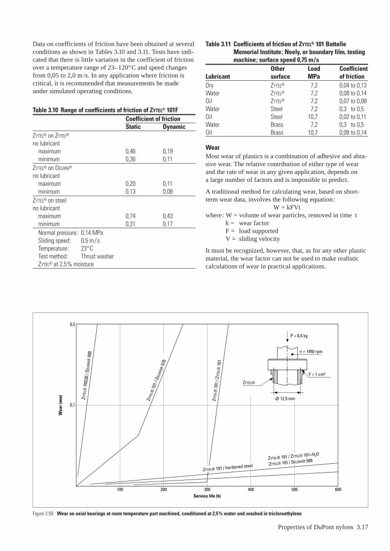
Data on coefficients of friction have been obtained at severalconditions as shown in Tables 3.10 and 3.11. Tests have indi-cated that there is little variation in the coefficient of frictionover a temperature range of 23–120°C and speed changesfrom 0,05 to 2,0 m /s. In any application where friction iscritical, it is recommended that measurements be madeunder simulated operating conditions.
Table 3.10 Range of coefficients of friction of ZYTEL® 101FCoefficient of frictionStatic Dynamic
ZYTEL® on ZYTEL®
no lubricantmaximum 0,46 0,19minimum 0,36 0,11
ZYTEL® on DELRIN®
no lubricantmaximum 0,20 0,11minimum 0,13 0,08
ZYTEL® on steelno lubricant
maximum 0,74 0,43minimum 0,31 0,17Normal pressure: 0,14 MPa Sliding speed: 0,5 m/s Temperature: 23°CTest method: Thrust washerZYTEL® at 2,5% moisture
Figure 3.59 Wear on axial bearings at room temperature part machined, conditio
Wea
r (m
m)
0,1
100Se
200
0,2
ZYTE
L® 10
1 / D
ELRI
N® 57
0
ZYTE
L® 7
0G30
/ DE
LRIN
® 5
00
Table 3.11 Coefficients of friction of ZYTEL® 101 BattelleMemorial Institute; Neely, or boundary film, testingmachine; surface speed 0,75 m/s
Other Load CoefficientLubricant surface MPa of frictionDry ZYTEL® 7,2 0,04 to 0,13Water ZYTEL® 7,2 0,08 to 0,14Oil ZYTEL® 7,2 0,07 to 0,08Water Steel 7,2 0,3 to 0,5Oil Steel 10,7 0,02 to 0,11Water Brass 7,2 0,3 to 0,5Oil Brass 10,7 0,08 to 0,14
WearMost wear of plastics is a combination of adhesive and abra-sive wear. The relative contribution of either type of wearand the rate of wear in any given application, depends on a large number of factors and is impossible to predict.
A traditional method for calculating wear, based on short-term wear data, involves the following equation:
W = kFVtwhere: W = volume of wear particles, removed in time t
k = wear factorF = load supportedV = sliding velocity
It must be recognized, however, that, as for any other plasticmaterial, the wear factor can not be used to make realisticcalculations of wear in practical applications.
Properties of DuPont nylons 3.17
ned at 2,5% water and washed in tricloroethylene
rvice life (h)300 400 500 600
F = 1 cm2
n = 1450 rpm
P = 0,4 kg
ZYTEL®
Ø 12,5 mmZYTE
L® 1
01 /
ZYTE
L® 1
01
ZYTEL® 101 / DELRIN® 500
ZYTEL® 101 / hardened steel
ZYTEL® 101 / ZYTEL® 101+H2O

More reliable tests have been carried out on axial bearings of ZYTEL® against various materials. The results of some ofthese tests are shown in Figure 3.59. Again these data shouldbe used mainly for comparative purposes.
As for any plastic material, the geometric shape of the wearsurface is of the utmost importance as far as wear is con-cerned. Particular care must thus be taken in obtaining goodmoulded parts; in this respect it must be noted that an incor-rectly designed part will be impossible to mould correctlyeven by the best of processors. Also dimensional variationsmust be taken into account.
3.18 Properties of DuPont nylons
The maximum PV limit value for ZYTEL® 101 on a hardenedsteel shaft is 0,1 MPa × m/s. This value should be taken onlyas a rough estimate of the behaviour of a ZYTEL® bearing. An accurate and complete testing on moulded parts in theactual service conditions should always be done and anyextrapolation or accelerated test should be avoided.
The excellent abrasion and wear characteristics of ZYTEL®
is further enhanced by the addition of KEVLAR® para-aramidfibres. ZYTEL®-KEVLAR® SFC70K20 is a short fibre compositecontaining 20% KEVLAR® fibre which is at least five timesmore wear resistant than unreinforced nylon and virtuallyeliminates abrasion of the counter surface.

Electrical propertiesZYTEL® nylon resins are widely used in electromechanicalparts because of their excellent mechanical properties, chem-ical resistance, heat resistance and self-extinguishing charac-teristics. This combination of properties permits ZYTEL® tobe used in coil forms, connectors, strain relief grommets, terminal blocks and tough overcoatings on wire insulation.
Parts made of ZYTEL® are generally used in electrical applica-tions requiring 600 volts or less and frequencies of 400 cyclesper second or lower. Power losses increase with increasingtemperature, frequency and moisture.
Some electronic applications, such as large microwave trans-mitters, experience high electrical losses because of the highfrequencies and the high heat sometimes encountered.
Moisture and temperature affect the volume resistivity,dielectric strength and dissipation factor for ZYTEL®. Theeffect of moisture can be minimized by using ZYTEL® 151 or 158 which are 612 nylons with lower moisture absorptionthan 66 nylons.
The short-time dielectric strength, as measured by ASTMD149, changes with thickness, moisture content and tempe-rature. As the thickness and moisture content increase, thedielectric strength decreases (Figure 4.01). As the temperatureincreases, the dielectric strength decreases (Figure 4.02a), andthe volume resistivity decreases (Figure 4.02b). Increasingmoisture content causes decreased volume resistivity (Figure4.03). Note that ZYTEL® 151 a 612 nylon, reaches moisturesaturation at a lower level than ZYTEL® 101, a 66 nylon, and retains higher volume resistivity. Volume resistivitymeasurements were made according to ASTM D257.
The dielectric constant increases rapidly with increasing tem-perature or moisture content as shown in Figures 4.04–4.05.Dielectric constant measurements were made in accordancewith ASTM D150. Since maintaining constant moisture and temperature conditions over the test period is difficult,the curves represent only general values for these conditions.
4 – Other properties of polyamide resD
iele
ctri
c st
reng
th (V
/mm
)
Thickness (mm)
80000
60 000
40 000
20 000
4321ZYTEL® 151 saturated 8,5% water
ZYTEL® 151 dry as moulded to saturated(moisture caused no measured change during test)
ZYTEL® 101 50% RH equilibrium
Figure 4.01 Short time dielectric strength of ZYTEL® vs. thickness measured at 23°C
Other properties of polyamide resins 4.1
The dissipation factor increases with increasing temperatureand moisture. Measurements of change were made usingASTM D150 and are shown in Figures 4.06–4.07.
Many compositions of ZYTEL® nylon have been rated by Underwriters’ Laboratories (UL) in its ComponentRecognition Program for polymeric materials. The UL ratings of ZYTEL® nylons are discussed in Section 8.
ins
Die
lect
ric
stre
ngth
(V/m
m)
Temperature (°C)
20000
15000
10000
5000
125
ZYTEL® 151
ZYTEL® 101
Measurements made using 3,2 mm thick discs
100755025Vo
lum
e re
sist
ivity
(ohm
. cm
)
Temperature (°C)
1016
1014
1012
1010
108
40 80 120 160 200
ZYTEL® 101
ZYTEL® 151
Volu
me
resi
stiv
ity (o
hm .
cm)
Moisture content (%)8642
1016
1014
1012
1010
108
106
ZYTEL® 101ZYTEL® 151
Saturation
Saturation
Figure 4.03 Effect on moisture content on volume resistivity at 23°C
Figure 4.02a Effect of temperature on dielectric strength of ZYTEL®
Figure 4.02b Volume resistivity vs. temperature, dry as moulded

Die
lect
ric
cons
tant
Temperature (°C)
1016
1014
1012
1010
108
200
ZYTEL® 15150% RH
15010050
ZYTEL® 10350% RH
ZYTEL® 10150% RH
ZYTEL® 151dry as moulded
Die
lect
ric
cons
tant
Moisture content (%)8642
50% RH equilibrium
ZYTEL® 151
ZYTEL® 101
50
40
30
20
10
30
Tang
ent (
�)
Temperature (°C)50 100 150
20
10
5
32
1
0,5
0,30,2
0,1
0,05
0,030,02
0,01
ZYTEL® 151
ZYTEL® 101
Figure 4.04 Dielectric constant vs. temperature measured at 100 Hz. Samplesconditioned as indicated. Typical values based on laboratorymeasurements
Figure 4.05 Effect of moisture on dielectric constant measured at 100 Hz, using 3,3 mm thick plaques at 23°C.Typical values based on laboratory measurements
Figure 4.06 Dissipation factor vs. temperature (100 Hz). Samples conditioned to 50% RH at 23°C.Typical values based on laboratory measurements
4.2 Other properties of polyamide resins
FlammabilityGeneralFlammability and smoke-generating characteristics of plas-tics have come under scrutiny in recent years and a varietyof laboratory-type tests have been developed to define theseproperties. Agencies within the Federal Government, as wellas outside organizations such as the American Society forTesting Materials, the Underwriters’ Laboratories, Inc. andmany industrial corporations have contributed to new testdevelopment. Currently, a large number of procedures fordefining many aspects of flammability are available for setting up safety and acceptability standards.
The individual tests are generally intended to predict thebehaviour of the material during burning or during exposureto intense heat, as in a burning building or aircraft. Here,conditions are legion. Hence, a reason for many individualprocedures is evident. There have been many attempts by thePlastics Industry to duplicate catastrophic fire in laboratorytests; however, the correlation of laboratory test data withactual conflagration remains controversial. The major contri-bution of the tests is to rank the various materials relative to each other and to the particular specifications.
The behaviour of ZYTEL® nylon resins when tested by theseprocedures is of importance to the designer, since it is neces-sary to know whether the material and proposed design willpass certain governmental or industrial codes. The followingtests are among those referred to in many government andindustrial specifications. Test data on some ZYTEL® nylonresins are shown in Tables 4.01 and 4.02. Table 4.02 showsalso how ZYTEL® compares with other types of plastic mate-rials in flammability and smoke generation.
Flame retardant compositionsThe ZYTEL® product line includes a range of materials whichhave been modified to inhibit burning and thus give superiorperformance in many of the tests listed below. These flameretardant grades are designated ZYTEL® FR. Please consultyour DuPont representative for full description of thesemodified materials.
0,4
0,3
0,2
0,1
Tang
ent (
�)
Moisture content (%)
ZYTEL® 151
2
ZYTEL® 101
4 6 8
Figure 4.07 Effect of moisture on dissipation factor measured at 100 Hz,samples at 23°C
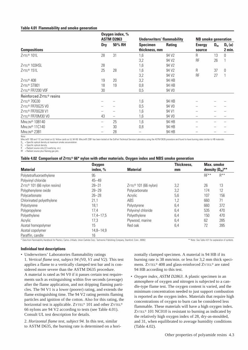
Table 4.01 Flammability and smoke generationOxygen index, %ASTM D2863 Underwriters’ flammability NB smoke generationDry 50% RH Specimen Rating Energy Dm Ds (a)
Compositions thickness, mm source 2 min.ZYTEL® 101L 28 31 1,6 94 V2 R 13 0
3,2 94 V2 RF 26 1ZYTEL® 103HSL 28 1,6 94 V2ZYTEL® 151L 25 28 1,6 94 V2 R 37 0
3,2 94 V2 RF 27 1ZYTEL® 408 19 20 3,2 94 HBZYTEL® ST801 18 19 0,8 94 HBZYTEL® FR7200 V0F 30 0,5 94 V0Reinforced ZYTEL® resinsZYTEL® 70G30 – – 1,6 94 HB – – –ZYTEL® FR70G25 V0 – – 0,5 94 V0 – – –ZYTEL® FR70G28 V1 – – 1,6 94 V1 – – –ZYTEL® FR70M30 V0 43 – 1,6 94 V0 – – –MINLON® 10B140 – 25 1,6 94 HB – – –MINLON® 11C140 – 30 0,8 94 HB – – –MINLON® 23B1 – 28 – 94 HB – – –Note:MINLON® 10B and 11C are listed on UL Yellow cards as UL 94 HB. MINLON® 23B1 has been tested at the DuPont Technical Services Laboratory using the ASTM D635 procedure and found to have burning rates similar to HB materials.Dm = Specific optical density at maximum smoke accumulation.Ds = Specific optical density.R = Radiant source only (2,5 watts/sq. cm.)RF = Radiant source plus flaming gas jets.
Table 4.02 Comparison of ZYTEL® 66* nylon with other materials. Oxygen index and NBS smoke generationOxygen Thickness, Max. smoke
Material index, % Material mm density (Dm)**Polytetrafluoroethylene 95 RF** R**Polyvinyl chloride 45–49ZYTEL® 101 (66 nylon resins) 28–31 ZYTEL® 101 (66 nylon) 3,2 26 13Polyphenylene oxide 28–29 Polycarbonate 3,2 174 12Polycarbonate 26–28 Acrylic 5,6 107 156Chlorinated polyethylene 21,1 ABS 1,2 660 71Polystyrene 18,1 Polystyrene 6,4 660 372Polypropylene 17,4 Polyvinyl chloride 6,4 535 470Polyethylene 17,4–17,5 Polyethylene 6,4 150 470Acrylic 17,3 Plywood, marine 6,4 62 285Acetal homopolymer 15 Red oak 6,4 72 395Acetal copolymer 14,8–14,9Paraffin, candle 16* Data from Flammability Handbook for Plastics, Carlos J.Hilado, Union Carbide Corp.; Technomic Publishing Company, Stamford, Conn., 06902. ** Note: See Table 4.01 for explanation of symbols.
Individual test descriptions• Underwriters’ Laboratories flammability ratings
1. Vertical flame test, subject 94 (V0, V1 and V2). This testapplies a flame to a vertically clamped test bar and is con-sidered more severe than the ASTM D635 procedure. A material is rated as 94 V0 if it passes certain test require-ments such as extinguishing within five seconds (average)after the flame application, and not dripping flaming parti-cles. The 94 V1 is a lower (poorer) rating, and extends theflame extinguishing time. The 94 V2 rating permits flamingparticles and ignition of the cotton. Also for this rating, thehorizontal test is applicable. ZYTEL® 101 and other ZYTEL®
66 nylons are 94 V2 according to tests (see Table 4.01).Consult UL test description for details.
2. Horizontal flame test, subject 94. In this test, similar to ASTM D635, the burning rate is determined on a hori-
Other properties of polyamide resins 4.3
zontally clamped specimen. A material is 94 HB if itsburning rate is 38 mm/min. or less for 3,2 mm thick speci-mens. ZYTEL® 408 and glass-reinforced ZYTEL® are rated94 HB according to this test.
• Oxygen index, ASTM D2863. A plastic specimen in anatmosphere of oxygen and nitrogen is subjected to a can-dle-type flame test. The oxygen content is varied, and theminimum concentration needed to just support combustionis reported as the oxygen index. Materials that require highconcentrations of oxygen to burn can be considered lessflammable. These materials will have a high oxygen index.ZYTEL® 101 NC010 is resistant to burning as indicated bythe relatively high oxygen index of 28, dry-as-moulded,and 31, when equilibrated to average humidity conditions(Table 4.02).

• Smoke density, ASTM D2843. A specimen is burned in aspecial chamber (XP-2) under continuous ignition. Thegeneration of smoke causes a reduction in the intensity ofa light beam. This is measured through the duration of thetest and results are expressed in terms of maximum percentlight absorption and a smoke density rating. The procedureis intended to provide a relative ranking of the smoke-producing characteristics of plastics under controlled stan-dardized conditions. Under the conditions of this laboratorytest, ZYTEL® 101 shows little smoke development (Table 4.01).
• NBS smoke generation. A procedure for measuring changesin optical density due to smoke generated by plasticsexposed to a radiant and radiant plus flaming energy sourceshas been developed by the National Bureau of Standards.The equipment is currently commercially available, andthe ASTM is reviewing the procedure. ZYTEL® nylonsshow up particularly well when compared with such mate-rials as polyvinyl chloride or ABS polymers. Data for non-reinforced materials are shown in Table 4.01 and 4.02.Smoke generation of glass-reinforced ZYTEL® is slightlyhigher than for nonreinforced.
• Flammability behaviour of ZYTEL® nylon resins. ZYTEL®
nylons readily pass the Federal Highway AdministrationNotice of Proposed Motor Vehicle Safety Standard No. 302,‘‘Flammability of Interior Materials, Passenger Cars,Multipurpose Passenger Vehicles, Trucks and Buses’’.They also easily pass the horizontal flame test section of the FAA Notice of Proposed Rule Making, ‘‘TransportCategory Airplanes, Crashworthiness and PassengerEvacuation’’, Federal Air Regulation 25-15. Most ZYTEL®
compositions pass the severe 60-second ignition verticaltest section of the FAA tests.
Light transmissionUnpigmented and unreinforced ZYTEL® nylon is relativelytranslucent in thin sections <3,2 mm. Because of this, ZYTEL®
has been used extensively in the automotive and aircraftindustries for dome and courtesy lights.
4.4 Other properties of polyamide resins
Waven0,4 0,3 0,2
Wave2,5 3 4 65
1,51
0,50,4
0,2
0
Abs
orba
nce
Figure 4.10 Infrared absorbance curve of ZYTEL® 101 nylon resin. Film 13 µm thick
100
80
60
40
20
Perc
ent t
rans
mitt
ance
Wavelength (µm)0,60,50,40,3
Violet Blue Green Yellow Red
0,1 mm
1,55 mm
100
80
60
40
20
Perc
ent t
rans
mitt
ance
Wavelength (µm)
0,1 mm
0-100% full scale
0-10% full scale
2,521,51
1,55 mm
Figure 4.08 Spectral transmittance curve of ZYTEL® 101 nylon resin. Ultraviolet and visible region 0,275–0,65 µm Cary Model 14 withintegrating sphere. Sample thickness 0,1 and 1,55 mm. Transmittance vs. wavelength
Figure 4.09 Spectral transmittance curve of ZYTEL® 101 nylon resin. Near infrared region 0,6–2,6 µm Cary Model 14 without integratingsphere. Sample thickness 0,1 and 1,55 mm. Transmittance vs. wavelength
umber (µm–1)0,15 0,1 0,05
length (µm)7 8 9 10 12 15 20 30 40 50
with Perkin-Elmer model 621 spectrophotometer. Absorbance vs. wavelength
ZYTEL® 151 is even more translucent than ZYTEL® 101. Forsustained exposure to heat, ZYTEL® 103 is sometimes pre-ferred although its colour is darker.
Spherulites are normally present in ZYTEL® and scatter light,thereby making the section translucent but not transparent.In fabricating thin sections by extrusion or moulding, how-ever, sudden cooling may be utilized to form essentiallyamorphous sections of about 0,025 mm thickness. These areessentially transparent. Transmission characteristics in theultraviolet and visible ranges and absorbance in the infraredranges are given in Figures 4.08 to 4.10.
ZYTEL® 330 is a completely amorphous polyamide and istransparent to visible light. The property balance of this resindiffers in some way, from semi-crystalline polyamides, anddetails of this material should be requested from your DuPontrepresentative.
Thermal propertiesCoefficients of thermal expansion for some unreinforcedZYTEL® grades, measured at different temperatures, are givenin Table 4.03. Thermal expansion is an important factor inplastic design.
For reinforced nylons the expansion coefficient in flow direc-tion generally is different from the one in transverse direction,resulting in different shrinkages in both directions, whichcan lead to warped parts after cooling down after moulding.Changed gate positions (flow directions) and optimal mouldcooling can help to reduce the unwanted warpage to a mini-mum.
Values for specific heat and thermal conductivity are givenin Tables 4.05 and 4.07. For viscosity values as a function ofshear rate at different temperatures around the melt tempera-ture of the materials listed in Table 4.07, see CAMPUS 2.4.
The heat deflection temperature, ISO 75-I-2, is the tempera-ture at which a standard test bar deflects 0,25 mm under astated stress level of either 0,45 or 1,82 N/mm2. Heat deflec-tion temperatures reported in the literature may sometimesfail to agree because internal stress and absorbed moistureaffect the experimentally obtained values. In Table 4.06, dataare shown for dry-as-moulded specimens in which internalstress was relieved by annealing.
The heat deflection temperatures of ZYTEL® nylon resins donot relate to melting or upper-use-temperature.
Consider the case of a ZYTEL® nylon test bar under a givenload at a variable temperature. Thermal plasticizing of thenylon as the temperature increases results in a modulusreduction and an increased deflection. Most of this deflec-tion is accordingly recoverable when the load is removed.Amorphous plastics, on the contrary, do not show this recov-ery when the load is removed from the test bar.
Table 4.03 Coefficient of linear thermal expansion, mm /mm/°CTemperature, °C ZYTEL® 101 ZYTEL® 151 ZYTEL® 408–40 63 × 10–6 72 × 10–6 61 × 10–6
–0 72 × 10–6 81 × 10–6 65 × 10–6
–23 81 × 10–6 90 × 10–6 72 × 10–6
–77 90 × 10–6 108 × 10–6 90 × 10–6
Note: The values shown are based upon dry as moulded specimens. The coefficient of expansion is somewhatdependent on both temperature and moisture content. For example at 23°C dry, ZYTEL® 101 has a coefficient of 81 × 10–6/°C–1 but at saturation it has a coefficient of 117 × 10–6/°C–1.
Table 4.04 Coefficient of linear thermal expansion, mm /mm/°CMaterial C.L.T.E RemarksMINLON® 10B, MINLON® 11C,
MINLON® 22C 36 × 10–6 DryZYTEL® 7OG30HSL,
ZYTEL® 77G33HSL 23 × 10–6 In flow directionZYTEL® 70G43HSL,
ZYTEL® 77G43HSL 23 × 10–6 In flow direction–
Table 4.05 Specific heatZYTEL® 1011 ZYTEL® 151
Specific heat kJ/kg · °C kJ/kg · °Cbelow 0°C 1,3 1,3
0–50°C 1,5 1,750–100°C 1,9 2,1
100–200°C 2,3 2,5–
Table 4.06 Heat deflection temperature*0,43 MPa 1,8 MPa
Material Temperature, °C Temperature, °CZYTEL® 101 235 80ZYTEL® E42 235 80ZYTEL® 408 230 69ZYTEL® 151 180 90ZYTEL® 158 180 90*All materials annealed in oil at 50°C below melting point.
Other properties of polyamide resins 4.5

4.6 Other properties of polyamide resins
Table 4.07 Thermal properties of ZYTEL® and MINLON® resins, rheology data
Solid/liquid density Melt specific heat Latent heat ConductivityGrade kg/m3 J/kg · °C J/kg J/m · s · °CZYTEL® 101F 1140/950 2604 54012 0,127ZYTEL® 101L NC010 1140/950 2897 53594 0,135ZYTEL® 103HSLC 1140/950 2897 53594 0,135ZYTEL® 135F NC010 1140/1020 2504 43419 0,115ZYTEL® 408 NC010 1090/950 2776 55185 0,140ZYTEL® 450 NC010 1090/920 2734 47732 0,135ZYTEL® 490 NC010 1090/920 2843 43964 0,120ZYTEL® 42 NC010 1140/950 2705 52338 0,120ZYTEL® ST801 1080/920 2835 37683 0,136ZYTEL® 70G20HSL 1290/1120 2094 45220 0,160ZYTEL® 70G30HSL 1350/1200 2290 32240 0,180ZYTEL® 70G35HSL 1410/1270 2290 32659 0,186ZYTEL® 70G43L 1510/1280 2290 33077 0,176ZYTEL® 72G30HSL 1370/1210 2261 22819 0,186ZYTEL® 73G30 NC010 1360/1200 2357 50000 0,203ZYTEL® 73G45 NC010 1510/1345 2357 50245 0,205ZYTEL® 73G50 BK264 1560/1360 2357 50245 0,205ZYTEL® 79G13HSL 1210/1030 2186 33915 0,160ZYTEL® 80G33 HSIL 1340/1140 2537 26378 0,189MINLON® 10B140 NC010 1510/1280 2274 35171 0,201MINLON® 11C140 NC010 1480/1270 2144 28053 0,241MINLON® 13MM GY282 1240/1085 2600 41033 0,183MINLON® 13T2 1370/1170 2345 30816 0,208MINLON® 23B1 1460/1240 2236 33329 0,193MINLON® EFE6052 NC010 1620/1440 2300 23029 0,201MINLON® EFE6053 BK165 1470/1250 2554 23073 0,271

Resistance of ZYTEL® nylon resins to high temperaturesIntroductionDue to oxidation, plastic materials normally undergo proper-ty loss during exposure to high temperatures. The maximumtemperature for successful service depends upon the materialused as well as the environmental conditions. Because ZYTEL®
nylon resins resist high temperatures and withstand oils,greases and gasolines, they have been used for years in auto-motive, electrical and appliance applications.
Heat-resistant ZYTEL® nylonsZYTEL® 101, an unmodified moulding grade 66 nylon, hasbeen used widely in applications requiring exposure to heat.However, compositions with increased heat resistance havebeen developed for more severe conditions, e.g. ZYTEL®
103HSL and ZYTEL® 70G30HSLR. Ask your DuPont repre-sentative for a description of these special grades.
Engineering data on the behaviour of ZYTEL® nylons exposed to high temperaturesEngineering data on the behaviour of ZYTEL® at elevatedtemperatures have been obtained by exposing test specimensto oven-aging conditions for various time periods and thenmeasuring changes in key properties as a function of time.Information on property decay can be useful in comparingmaterials and estimating service life. However, service test-ing of parts under expected temperature conditions is recom-mended when feasible. This provides a more reliable basisfor defining their suitability for an intended application.
Tensile strength and impact strength are primary criteria formost design considerations and are used to express load-bearing strength and ability to withstand sudden shock orimpact. The ability of plastics to retain these properties with-out serious loss during prolonged exposure to service tem-peratures is important to many mechanical and electricalapplications.
The decay of properties for ZYTEL® nylons has been plottedin Figures 5.01–5.07. Data show the effects of oven exposureat different temperatures on the decay of tensile strength as a function of time.
5 – Effects of environment on ZYTEL®
100
75
50
25
1000 2000 3000
157°C
Exposure (h)4000
132°C 120°C
Tens
ile s
tren
gth
(MPa
)
Figure 5.01 Effect of air oven ageing of ZYTEL® 101 NC010 on tensile strength
Effects of environment on ZYTEL® 5.1
Figure 5.04 Effect of air oven ageing on tensile strength of ZYTEL® 408HSL BK009
125
100
75
50
25
4000300020001000Exposure (h)
Tens
ile s
tren
gth
(MPa
)
132°C
160°C
180°C
80
60
40
20
50004000300020001000Exposure (h)
85°C105°C
120°C
132°C
Tens
ile s
tren
gth
(MPa
)
0
Tens
ile s
tren
gth
(MPa
)
2000Exposure (h)
10000 3000
20
40
80
60
157°C
Figure 5.02 Effect of air oven ageing of ZYTEL® 103HSL on tensile strength
Figure 5.03 Effect of air oven ageing of ZYTEL® 151 NC010 on tensile strength
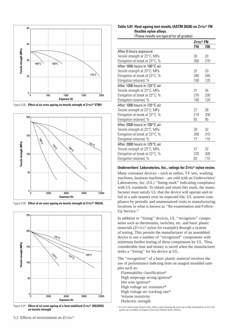
5.2 Effects of environment on ZYTEL®
0
Tens
ile s
tren
gth
(MPa
)
Exposure (h)
20
40
60
80
2000150010000 500
190°C 180°C
170°C
0
50
100
150
120006000 90000 3000
200
Tens
ile s
tren
gth
(MPa
)
Exposure (h)
150°C
132°C170°C
190°C
120006000 90000 3000Exposure (h)
0
50
100
150
200
Tens
ile s
tren
gth
(MPa
)
250
132°C
150°C157°C
170°C
Figure 5.07 Effect of air oven ageing of a heat stabilized ZYTEL® 70G33HSL on tensile strength
Figure 5.06 Effect of air oven ageing on tensile strength of ZYTEL® 70G33L
Figure 5.05 Effect of air oven ageing on tensile strength of ZYTEL® ST801
Table 5.01 Heat ageing test results (ASTM D638) on ZYTEL® FNflexible nylon alloys. (These results are typical for all grades)
ZYTEL® FN716 726
After 0 hours exposureTensile strength at 23°C, MPa 30 33Elongation at break at 23°C, % 260 270After 1000 hours in 100°C airTensile strength at 23°C, MPa 32 33Elongation at break at 23°C, % 260 340Elongation retained, % 100 120After 1000 hours in 125°C airTensile strength at 23°C, MPa 31 34Elongation at break at 23°C, % 270 330Elongation retained, % 100 120After 1000 hours in 135°C airTensile strength at 23°C, MPa 27 28Elongation at break at 23°C, % 218 258Elongation retained, % 83 95After 2000 hours in 100°C airTensile strength at 23°C, MPa 28 32Elongation at break at 23°C, % 200 310Elongation retained, % 77 110After 2000 hours in 125°C airTensile strength at 23°C, MPa 27 32Elongation at break at 23°C, % 220 300Elongation retained, % 83 110
Underwriters’ Laboratories, Inc., ratings for ZYTEL® nylon resinsMany consumer devices – such as radios, TV sets, washingmachines, business machines – are sold with an Underwriters’Laboratories, Inc. (UL) ‘‘listing mark’’ indicating compliancewith UL standards. To obtain and retain this mark, the manu-facturer must satisfy UL that the device will operate and /orfail in a safe manner over its expected life. UL assures com-pliance by periodic and unannounced visits to manufacturinglocations in what is known as ‘‘Re-examination and Follow-Up Service.’’
In addition to ‘‘listing’’ devices, UL ‘‘recognizes’’ compo-nents such as thermostats, switches, etc. and basic plasticmaterials (ZYTEL® nylon for example) through a system of testing. This permits the manufacturer of an assembleddevice to use a number of ‘‘recognized’’ components withminimum further testing of these components by UL. Thus,considerable time and money is saved when the manufacturerseeks a ‘‘listing’’ for his device at UL.
The ‘‘recognition’’ of a basic plastic material involves theuse of performance indexing tests on unaged moulded sam-ples such as:
Flammability classification*High amperage arcing ignition*Hot wire ignition*High voltage arc resistance*High voltage arc tracking rate*Volume resistivityDielectric strength
* ZYTEL® nylon resins listed in the yellow cards showing the most up-to-date information on ZYTEL®nylons are available on request from local DuPont Sales Offices.
Heat deflectionDimensional stabilityTensile strengthImpact strength
In addition, UL is interested in the long term behaviour ofthe following properties at temperatures above 50°C:
Electrical (dielectric strength)Mechanical – without impact (tensile strength)Mechanical – with impact (Izod or tensile impact)
This is done by a thermal aging procedure (UL Subject 746)utilizing moulded test bars and /or discs of specified thick-nesses with results plotted on an Arrhenius plot. This predictsthe temperature at which the specific property will decreaseto one half of its original, unaged value at 60 000 hours of use.
Most of these tests have been completed on the many com-positions of ZYTEL® nylon and are one file at UL under FileNo. E-41938.
Electrical propertiesDecay rates for electrical properties also are important designinformation. Our general experience has been that electricalproperties such as dielectric strength hold up usually betterthan mechanical properties. Spot checks on other electricalproperties have confirmed field experience which has dem-onstrated satisfactory electrical property retention even aftera considerable loss in mechanical properties has occurred.
Table 5.02 Examples of UL-rates ZYTEL® nylonsUL rating on
Nylon composition electrical properties,°CZYTEL® 101 and 101L (NC, WT, BK) 125ZYTEL® 103HSL (NC, BK) 130ZYTEL® 105 BK010A 125ZYTEL® 42 125ZYTEL® 151 and 158L 105
Resistance of ZYTEL® to hot water and steamIntroductionZYTEL® nylon resins are resistant to hot water and steam.Thus, ZYTEL® has found wide uses in such applications ashot water mixing valves, gears and baskets, equipment usedfor conveying in hot water and parts which must be subjectedto steam, as in a sterilization cycle. This section discusses theresistance of ZYTEL® to numerous hydrolytic environments.
Factors important to performance in hot water and steam• Temperature. Oxidative attack and embrittlement occur
more severely at higher temperatures. A 15°C increase intemperature may reduce life by 40–50%. However, theeffect of oxygen concentration in the water is sometimesmore important than temperature.
• Stagnant vs. fresh water. ZYTEL® is less affected by stag-nant boiling water than by boiling water aerated with air.As water is heated, the air flashes off to the atmosphereand at the boiling point, little oxygen remains. Water froma hot water heater is usually rich with air.
• Chlorine. The effect of municipal chlorinated water on the service life of parts of ZYTEL® is small and not easilydefined quantitatively. Laboratory prepared chlorine con-tents of up to 8 ppm do have a small effect on ZYTEL® andmay reduce service life 20–30%. Microcracking may occur.
• Internal stress. Moulded-in stress can be an importantfacet of expected life, particularly when potential stresscracking materials may be involved in service. Mouldedparts should be nearly stress free.
• Impact and fatigue. In water-mixing valves and similarparts, impact and fatigue conditions (from water hammer)are elements of service. Experience has demonstrated theability of ZYTEL® to withstand these conditions. However,for new applications involving impacts, service testingshould be used.
Specific composition for maximum hydrolytic resistanceFor severe conditions in steam or hot water, ZYTEL® 122 or70G30HSLR should be used. Both are hydrolysis resistant66 nylons.
Resistance of ZYTEL® to different types of water environmentThe interplay of factors in a contemplated water or steamenvironment can make the prediction of service life difficult.Although nothing is as definitive as end-use testing, dataobtained under several controlled conditions are useful indesign considerations and in new applications. Accordingly,data on property retention were studied under the followingenvironments: (1) stagnant water (without air), (2) freshwater (containing air) and (3) steam (containing air).
• Resistance of ZYTEL® to stagnant boiling water. In serviceconditions involving exposure to steam or hot water, oxy-gen is always present in some concentration. In this sec-tion, situations in which the oxygen concentration is loware considered and the hydrolytic environment is termed‘‘stagnant’’.
In these ‘‘stagnant’’ tests, test bars were placed in a vesselcontaining boiling water and the effect of exposure on ten-sile properties and impact strength were measured as afunction of time. Every three days, the water from the con-tainer was replaced with fresh water which was heatedimmediately to boiling. The effect of temperature on esti-mated service life of ZYTEL® nylon in stagnant water isshown in Table 5.03. The life estimations for various tem-peratures are based on the assumption of low concentra-tions of oxygen.
• Resistance of ZYTEL® to fresh water containing oxygen.Water heated to 80°C in a home appliance and dischargeddirectly into a water-mixing valve of a washing machine is supersaturated with respect to air (and oxygen). Thiswater, rich in air, is more severe than stagnant water.Service life of ZYTEL® is shorter in oxygen-rich water.Tests on air-rich water were run at 80°C, a temperaturecommon in home appliances. In the testing, 80°C waterwas continuously fed into a pressure cannister in whichtest bars were exposed to the combined effects of air andwater. The test was designed to simulate a washing machinewith fresh hot water filling the cannister every 30 seconds.
Effects of environment on ZYTEL® 5.3

5.4 Effects of environment on ZYTEL®
Test bars were removed periodically and tested for tensileproperties in order to measure decay. As shown in Figure 5.08, ZYTEL® 122 stands up significantly better thanZYTEL® 101. It is also apparent that water at 80°C contain-ing considerable air is more severe on ZYTEL® than is stag-nant water.
• Resistance of ZYTEL® to steam. ZYTEL® 122 is used for prolonged exposure to steam; ZYTEL® 101 for less severeexposure. The behaviour of ZYTEL® 122 in a steam auto-clave is shown in Table 5.04.
WeatheringGeneralMost plastic materials undergo some decay in properties andchanges in appearance during prolonged exposure to outdoorweathering. Natural and pigmented ZYTEL® nylon resinshave only moderate resistance to the effects of sunlight butspecial weather-resistant compositions retain their propertiesand appearance for years.
60
40
20
Rési
stan
ce à
la tr
actio
n, M
Pa
Durée, heures6000
ZYTEL® 122
40002000
ZYTEL® 101
ZYTEL® 70G30 HSL(100% HR)
Figure 5.08 Resistance of ZYTEL® 101, 122 and 70G30HSL to hot fresh water at 80°C
Table 5.03 Estimated service life of ZYTEL® 101 and 122 in stagnant hot water
Water Exposure hours based on point where elongationtemperature and impact resistance decrease 25–50%
Exposure hours Exposure hours°C ZYTEL® 101* ZYTEL® 122100 1500 500090 2000 650080 3000 1000070 8000 25000
* These data can be used also for estimating the useful life of ZYTEL® 103HS and 105. For hot water rich in air, reduce exposure hours by 30–50%.
Table 5.04 Effect of 120°C steam on ZYTEL® 122Property Units Control 200 hours 400 hoursTernsile strength MPa 73 74 70Elongation % 300 110 88
Time (h)
ZYTEL® 70G30HSL(100% RH)
Tens
ile s
treng
th (M
Pa)
ZYTEL® 101 in natural and colours has been used success-fully in outdoor applications. However, when exposure toultraviolet light is severe and sustained and when maximumtoughness must be retained over a period of years, weather-resistant compositions should be used.
Weather-resistant compositionsWeather-resistant compositions of ZYTEL® have been in ser-vice for more than 20 years. These materials contain a gradeof carbon that has been uniformly dispersed to screen outattack by ultraviolet light.
Compositions used for maximum retention of physical prop-erties are:
• ZYTEL® 105 BK010A. This is the preferred 66 nylon foroutdoor use.
• ZYTEL® 101 WT007. White compositions are sometimesused for aesthetic reasons although weathering resistanceis inferior to carbon-filled nylons. This 66 nylon maintainsits appearance and properties in humid climates but is poorin arid areas.
• Reinforced composites have performed well in weatheringtests. Ask your DuPont representative for a description ofthese special grades.
Properties observed in weathering studiesMoulded test parts exposed outdoors to ultraviolet radiationmay ultimately fail for one of the following reasons: (1) lossof strength, (2) loss of toughness or (3) change in appearance.
Changes in tensile and yield strength over the time periodstudied were determined using ASTM D638. Toughness wasmeasured using a mandrel bend test, in which test bars arebent rapidly 180° around a 3,2 mm diameter steel mandrel. A tough bar has the capability of being deformed in thismanner without breaking.
The relative viscosity of nylon is related to its molecularweight. Exposure of nylon that is inadequately stabilizedagainst ultraviolet light results in surface degradation with acorresponding drop in relative viscosity or molecular weight.The interest in relative viscosity accrues from the fact thatserious loss in this property is related to a comparable loss in toughness.
Change in appearance has been measured by colour differenceusing Adams units which are similar to National Bureau ofStandards (NBS) units.
Testing methodsThe effects of weathering on the properties of ZYTEL® havebeen determined by exposing test specimens outdoors in var-ious sections of the country and measuring property decayvs. time. Florida was selected as one location because of thehigh level of ultraviolet light radiation existing throughoutthe year. Arizona was also selected because of its uniquecombination of high ultraviolet radiation and arid conditions.
The exposure tests described in these localities representmore severe irradiation than would normally be expected inactual outdoor service. This is because all test samples are
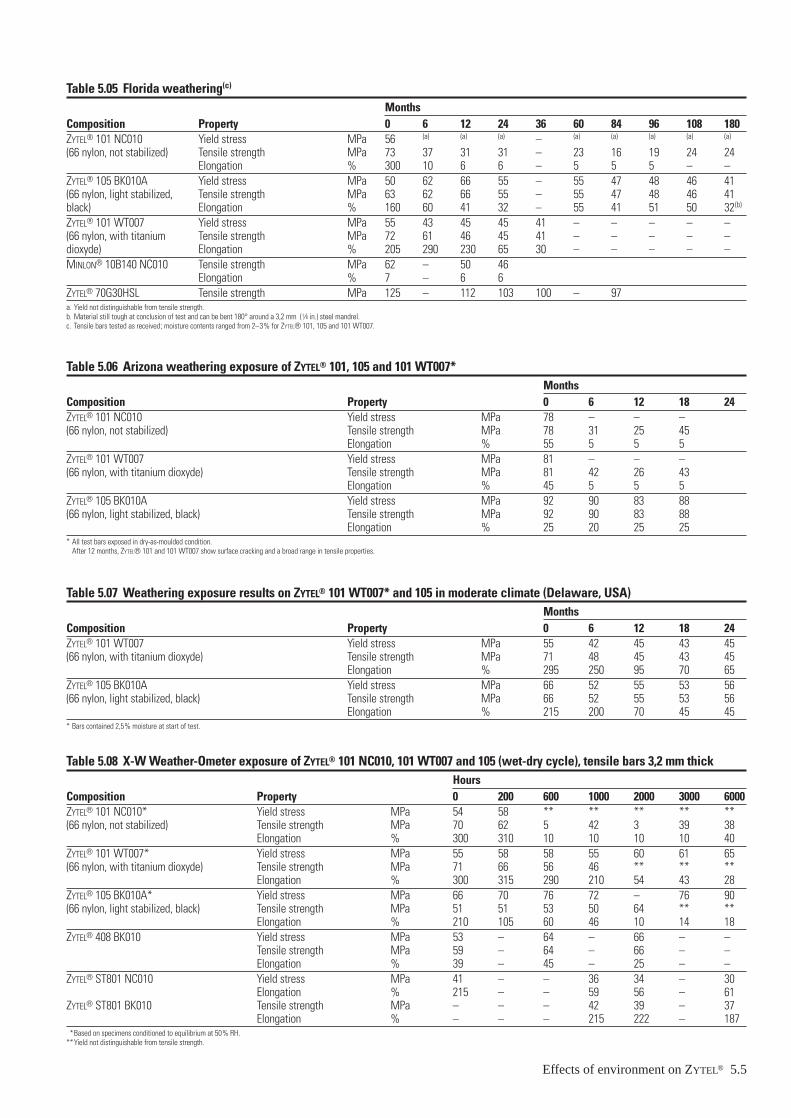
Effects of environment on ZYTEL® 5.5
Table 5.05 Florida weathering(c)
MonthsComposition Property 0 6 12 24 36 60 84 96 108 180ZYTEL® 101 NC010 Yield stress MPa 56 (a) (a) (a) – (a) (a) (a) (a) (a)
(66 nylon, not stabilized) Tensile strength MPa 73 37 31 31 – 23 16 19 24 24Elongation % 300 10 6 6 – 5 5 5 – –
ZYTEL® 105 BK010A Yield stress MPa 50 62 66 55 – 55 47 48 46 41(66 nylon, light stabilized, Tensile strength MPa 63 62 66 55 – 55 47 48 46 41black) Elongation % 160 60 41 32 – 55 41 51 50 32(b)
ZYTEL® 101 WT007 Yield stress MPa 55 43 45 45 41 – – – – –(66 nylon, with titanium Tensile strength MPa 72 61 46 45 41 – – – – –dioxyde) Elongation % 205 290 230 65 30 – – – – –MINLON® 10B140 NC010 Tensile strength MPa 62 – 50 46
Elongation % 7 – 6 6ZYTEL® 70G30HSL Tensile strength MPa 125 – 112 103 100 – 97a. Yield not distinguishable from tensile strength.b. Material still tough at conclusion of test and can be bent 180° around a 3,2 mm (1⁄8 in.) steel mandrel.c. Tensile bars tested as received; moisture contents ranged from 2–3% for ZYTEL® 101, 105 and 101 WT007.
Table 5.06 Arizona weathering exposure of ZYTEL® 101, 105 and 101 WT007*Months
Composition Property 0 6 12 18 24ZYTEL® 101 NC010 Yield stress MPa 78 – – –(66 nylon, not stabilized) Tensile strength MPa 78 31 25 45
Elongation % 55 5 5 5ZYTEL® 101 WT007 Yield stress MPa 81 – – –(66 nylon, with titanium dioxyde) Tensile strength MPa 81 42 26 43
Elongation % 45 5 5 5ZYTEL® 105 BK010A Yield stress MPa 92 90 83 88(66 nylon, light stabilized, black) Tensile strength MPa 92 90 83 88
Elongation % 25 20 25 25* All test bars exposed in dry-as-moulded condition.
After 12 months, ZYTEL® 101 and 101 WT007 show surface cracking and a broad range in tensile properties.
Table 5.07 Weathering exposure results on ZYTEL® 101 WT007* and 105 in moderate climate (Delaware, USA)Months
Composition Property 0 6 12 18 24ZYTEL® 101 WT007 Yield stress MPa 55 42 45 43 45(66 nylon, with titanium dioxyde) Tensile strength MPa 71 48 45 43 45
Elongation % 295 250 95 70 65ZYTEL® 105 BK010A Yield stress MPa 66 52 55 53 56(66 nylon, light stabilized, black) Tensile strength MPa 66 52 55 53 56
Elongation % 215 200 70 45 45* Bars contained 2,5% moisture at start of test.
Table 5.08 X-W Weather-Ometer exposure of ZYTEL® 101 NC010, 101 WT007 and 105 (wet-dry cycle), tensile bars 3,2 mm thickHours
Composition Property 0 200 600 1000 2000 3000 6000ZYTEL® 101 NC010* Yield stress MPa 54 58 ** ** ** ** **(66 nylon, not stabilized) Tensile strength MPa 70 62 5 42 3 39 38
Elongation % 300 310 10 10 10 10 40ZYTEL® 101 WT007* Yield stress MPa 55 58 58 55 60 61 65(66 nylon, with titanium dioxyde) Tensile strength MPa 71 66 56 46 ** ** **
Elongation % 300 315 290 210 54 43 28ZYTEL® 105 BK010A* Yield stress MPa 66 70 76 72 – 76 90(66 nylon, light stabilized, black) Tensile strength MPa 51 51 53 50 64 ** **
Elongation % 210 105 60 46 10 14 18ZYTEL® 408 BK010 Yield stress MPa 53 – 64 – 66 – –
Tensile strength MPa 59 – 64 – 66 – –Elongation % 39 – 45 – 25 – –
ZYTEL® ST801 NC010 Yield stress MPa 41 – – 36 34 – 30Elongation % 215 – – 59 56 – 61
ZYTEL® ST801 BK010 Tensile strength MPa – – – 42 39 – 37Elongation % – – – 215 222 – 187
**Based on specimens conditioned to equilibrium at 50% RH.**Yield not distinguishable from tensile strength.

on racks at an angle of 45° to the horizontal and facing theequator. (See ASTM D1435-65, Recommended Practice forOutdoor Weathering of Plastics).
Specialized equipment has been designed to produce ultra-violet radiation in higher concentrations than is found out-doors. The X-W Weather-Ometer, made by Atlas ElectricDevices of Chicago, is an example of this type of equipmentand has been used in DuPont accelerated weathering studies.
Weathering in various locations• Florida. Florida weathering data are shown in Table 5.05
and may be summarized as follows:
1. ZYTEL® 101 NC010 shows substantial loss of toughnessat six months. The tensile strength, however, remains at 24 MPa after 180 months exposure.
2. ZYTEL® 105 is still tough and strong at 180 months.
3. ZYTEL® 101 WT007 is tough and strong at 36 months.
• Arizona. Experience with Arizona exposure tests has shownthis climate to be more severe on ZYTEL® 101 WT007 andZYTEL® 101 NC010 than on ZYTEL® 105 BK010A. For Arizona or similar climates, black stabilized composi-tions such as ZYTEL® 105 should be used. Arizona expo-sure data for ZYTEL® 101, 105 and 101 WT007 are shownin Table 5.06.
5.6 Effects of environment on ZYTEL®
• Delaware. Wilmington ultraviolet light radiation is gener-ally less severe than in Florida and exposed parts havegenerally been found to withstand Delaware better thanFlorida. Some data on weathering exposure results inDelaware on ZYTEL® 101, WT007, and ZYTEL® 105 areshown in Table 5.07.
X-W Weather-OmeterAn artificial weathering apparatus is sometimes used insteadof direct exposure. In such an exposure, with a carbon arc asthe source of radiation and periodic water spray to simulaterain, the test bars are subjected to accelerated weatheringconditions. Although there is no precise relationship betweenoutdoor weathering and the accelerated X-W Weather-Ometertests, it is believed that 400–1000 hours produces a similareffect to a year in Florida. The effect of exposure in an X-WWeather-Ometer on the properties of ZYTEL® 101 NC010,101 WT007, 105, 408 and ST801 are shown in Table 5.08.Weather-Ometer information about MINLON® 10B140 isshown in Tables 5.09
Table 5.09 Exposure of MINLON® 10B140 to Weather-Ometer(Xenon lamp)
Wet-dry cycles, hoursProperties 0 1000 3000 5000Tensile strength MPa 98 80 77 60Elongation % 3 3 3 4

Permeability and resistance to chemicals and reagentPermeabilityPermeability refers to the passage of a gas or liquid througha solid barrier. ZYTEL® nylon is an excellent barrier materialbut like all thermoplastics, some chemicals will diffusethrough it at a measurable rate.
Tables 5.10 and 5.11 list permeation rates for common gasesand liquids. This data can be used to compare the barriercharacteristics of ZYTEL® as well as to calculate losses thatcan be expected through containers, film packages, conduitsor other barrier parts.
Permeability is a property which is most difficult to measureaccurately. It is dependent upon environmental pressure andtemperature, test apparatus, as well as upon the materials in-volved. Consequently, although the data in Tables 5.10 and5.11 are precise within the limits of the test procedure, theyshould be considered order-of-magnitude values. While mostof the permeation rates have been measured on ZYTEL® 42they can be used as good approximations for the permeabili-ty of other compositions of ZYTEL® nylon in the 66 family.
Table 5.10-A Permeation rates of various liquids from 2,5 mmthick bottles made from ZYTEL® 42
Permeation rate atLiquid 0,1 MPa in g/24 h/m2/mmKerosene 0,08Methyl salicylate 0,08Motor oil (SAE 10) 0,08Toluene 0,08Fuel oil B (isooctane-toluene blend) 0,02Water 1,2–2,4Carbon tetrachloride 2,0VMP naphtha 2,4
Table 5.10-B Permeation rates of various gases and liquids from film made from ZYTEL® 42Liquid Units RH % Temperature °C Permeation factorWater vapour transmission g · mm / m2 · d 50 23 0,39
100 32 7,9Oxygene cm3 · mm / m2 · d · N · mm–2 50 23 7–15,6Carbon dioxyne cm3 · mm / m2 · d · N · mm–2 50 23 35,0Nitrogen cm3 · mm / m2 · d · N · mm–2 50 23 2,7Helium cm3 · mm / m2 · d · N · mm–2 50 23 584Motor oil g · mm / m2 · d 50 23 0,006Petrol g · mm / m2 · d 50 23 0,04
Table 5.11 Air conditioning refrigerant permeation lossLoss*
DuPontMaterial CFC-12 HCF-134a ternary blend**Nitrile rubber 0,662 0,560 0,9386/66 nylon copolymer 0,067 0,077 0,178ZYTEL® FN 726 0,012 0,015 0,086** Lb/ft × yr at 93°C for a 5/8” ID × 12” × 1 mm thick hose with refrigerant at saturated vapour pressure.** HCFC-22 / HCFC-124 / HFC-152a.
Chemical resistance – GeneralZYTEL® nylon resins are outstanding in their resistance to a wide range of organic and inorganic substances. They arenot affected by, nor do they affect, lubricating oils and greases, and aliphatic and aromatic hydrocarbons (includingconventional fuels). Accordingly, they have found consider-able use in automotive and aircraft applications. In manyinstances, the combined resistance of ZYTEL® to both heatand oils has permitted the use of high service temperatures,although tests on individual oils or greases are essential toensure success.
ZYTEL® nylons are also resistant to a wide variety of propri-etary items such as paints and lacquers, cosmetic prepara-tions, detergents, aerosol preparations and food productsincluding animal and vegetable fats. As a result, they areused for the packaging of many of these products.
ZYTEL® nylon resins are resistant to a wide variety of organiccompounds, such as aldehydes, ketones, monohydroxyl alcohols, most esters, and most chlorinated aliphatic and aro-matic materials. Some of these compounds will be absorbedby nylons in limited quantities with resultant dimensionalchanges. Physical properties in general are not impaired,although some materials, such as alcohols, will somewhatplasticize the nylon with a reduction in tensile strength, yieldand modulus, and an increase in elongation and impactstrength. Higher carbon-containing members of a homologousseries are absorbed less. Partially halogenated hydrocarbons,such as methylene chloride, chloroform and ethylene dichlo-ride, are absorbed in limited amounts and result in someplasticizing action resembling that of water.
Organic materials which do affect ZYTEL® generally do sothrough some degree of solvent action. Phenols and formicacid are powerful solvents and are used in certain bondingtechniques. Trichloroacetic acid and some fluoroalcoholshave similar action. Use in organic acids should be approachedwith caution. Acetic acid slowly attacks ZYTEL®; stronger
Effects of environment on ZYTEL® 5.7
acids have a more rapid effect. The higher fatty acids, suchas stearic acid, present no problem.
ZYTEL® resists many inorganic reagents. Unlike most metals,it is not affected by electrolytic corrosion as found in andaround salt water and in many industrial atmospheres.ZYTEL® resists even high concentrations of alkalies and isused in alkaline batteries. Some salts – either through acidreaction or by a specific solvent effect – will attack ZYTEL®.

Such salts as calcium thiocyanate, calcium bromide, calciumchloride, potassium thiocyanate and zinc chloride are knownto have solvent action – particularly in high (50–80%) con-centrations and at elevated temperatures.
Factors important to service life of a nylon in a chemical environmentThe designer must define the specific conditions of thechemical environment before he can determine whether theprobability for a successful application is good. Some ofthese conditions are:
• Temperature. Depending on the specific reagent, servicelife can be significantly reduced by an increase in tempera-ture. Acids and oxidizing agents are particularly harmfulto nylons at higher temperatures. It is difficult to general-ize on the quantitative aspects of increased temperaturesalthough a 15°C rise in temperature will frequently reduceservice life by 25–50%.
• Chemical concentration. Chemical concentration has abearing on service life of nylons. This is true for acids andwill depend greatly upon the pH. The effect of concentra-tion will vary from one material to another and generaliza-tions are impossible to make.
• Time. This is important in defining the suitability of anapplication in a particular reagent. Does the applicationinvolve 60 days of intermittent exposure or two years ofcontinuous exposure?
• Part surface to weight ratio. Here the ratio of surface areato weight is important. The greater this ratio, the morerapid the attack.
• Stress level. Although nylons are very resistant to attackfrom a wide variety of chemical agents, a few inorganicsalts can cause severe breakdown of nylons under stress.Zinc chloride, for example, is especially harmful to 66 nylons such as ZYTEL® 101, but has a lesser effect on 612 nylons such as ZYTEL® 151. End-use tests shouldalways be employed to determine the suitability of a nylonfor a particular application.
Effect of specific types of chemicals• Solvent and reagents. The data presented in Table 5.12
covers the effect of specific solvents and reagents onZYTEL® nylon resins. ZYTEL® is resistant to a wide varietyof chemical compounds and although some materials suchas water, alcohols and partially chlorinated hydrocarbonsare absorbed in limited quantities, physical properties aregenerally not impaired. Some plasticizing action oftenaccompanies the absorption of solvents and the dimensionsnormally increase slightly. In Table 5.12, changes in weightand dimensions after exposure are expressed as a percentageof the initial weight and length measurements.
• Automotive oils, greases, lubricants, hydraulic and trans-mission fluids ordinarily used at high temperature. Testshave been run on a variety of brake fluids, chassis lubri-cants, power steering fluids and motor oils. These materi-als are complex formulations consisting of a hydrocarbon-oil base or other compound plus chemical additives such
®
5.8 Effects of environment on ZYTELas antioxidants, thermal stabilizers, detergents, viscosityextenders or other agents. ZYTEL® nylons have generallygood resistance to these proprietary automotive and air-craft materials and are widely used in unter-the-hoodapplications. At temperatures in excess of 65°C, however,certain specific lubricant additives may effect performance.
Test data on the behaviour of ZYTEL® exposed to theseautomotive fluids at elevated temperatures is essential tothe success of the intended use. This matter is discussed indetail in an SAE paper*.
Another approach designed to measure the suitability ofZYTEL® in various environments involving exposure toautomotive materials is discussed in a second portion ofthat same paper**. This describes how automotive partswere obtained and evaluated after extended in-use service.
• Petrols. ZYTEL® nylons are outstanding in their resistanceto conventional automotive fuels. ZYTEL® shows an aver-age weight increase of 0,6% and an average dimensionalchange of +0,01% after 270 days exposure at 23°C to avariety of petrols representing high and low test materialfrom major suppliers.
• Acids, bases and oxidizing agents. ZYTEL® nylons are veryresistant to alkalies even at high concentrations up to 40%.They are, however, rapidly attacked by strong mineralacids and / or oxidizing agents especially at high operatingtemperatures. Use in dilute solutions of acids or oxidizingagents under ambient conditions is often possible, butactual or simulated service tests should be conducted toascertain the suitability of ZYTEL® for a particular applica-tion.
• Soaps and detergents. Tests conducted at 80°C shows thatZYTEL® nylons have excellent resistance to standard deter-gent formations such as ‘‘Tide’’, ‘‘Dreft’’, ‘‘Dash’’, ‘‘Oxy-dol’’, ‘‘Oakite’’, Calgon and Fels Naphtha soap.
Table of chemical resistanceInformation on the resistance of unreinforced ZYTEL® to spe-cific reagents is shown in Table 5.12. Ratings of excellent,satisfactory or unsatisfactory are based upon property reten-tion for test bars exposed to the specified concentrations ofthe materials for the indicated time periods and temperature.Chemical resistance information in Table 5.12 is based onappearance and on retention of physical properties normallyafter drying to remove residual moisture and reagents.
Table 5.13 shows absorption data and axial transversedimension changes for glass reinforced ZYTEL® nylon resinafter immersion in chemicals.
The resistance of glass-fibre reinforced ZYTEL® to stresscracking when test bars are exposed to chemicals is illustratedin Table 5.14. None of a spectrum of chemical types causedstress cracking.
** ‘‘The Suitability of 66 Nylon Resins for Moulded Parts Insolving Long-Term Resistance to Heat,Gasoline and Salt’’, Society of Automotive Engineers, Mid-Year Meeting, Detroit, Michigan, May 18–22, 1970, Paper No. 700485.
** ‘‘Evaluating the Effect of Extended Service in Automobiles on Parts Made of 66 Nylon and AcetalHompolymer’’, Society of Automotive Engineers, Mid-Year Meeting, Detroit, Michigan, May 18–22, 1970, Paper No. 700485.

MINLON® engineering thermoplastics exhibit low absorptionof many chemicals as shown in Table 5.15. However, a num-ber of compounds such as glycols, glycerin and polyhydricalcohols are absorbed by MINLON® engineering thermoplas-tics and have a plasticizing effect similar to that of water.
Certain organic liquids dissolve MINLON®. These includephenols, formic acid, trichloroacetic acid, and some fluoro-alcohols.
Table 5.12 Chemical resistance of unreinforced ZYTEL® nylon 66 reExposureconditio
Type nylonChemical resin** °CAcetaldehyde 90 52Acetic acid 5 23 3
5 23 75 ZYTEL® 158 23 9
Acetone 100 23 36100 50 36100 ZYTEL® 158 23 9
Alum. ammonium 10 24Aluminium salts of mineral acids 10 23
10 52Ammonia, liquid 100 –33
100 –33 1100 24 20
Ammonium carbonate 10 23Ammonium chloride 10 52Ammonium hydro¥ide 10 23 36
10 70 36n-Amyl acetate 100 ZYTEL® 151 98 4Antimony trichloride 10 24AROCLOR 1242 100 23 3Barium chloride 10 24Barium sulfate 10 24Barium sulfide 10 24Benzene 100 23
100 ZYTEL® 151 23 9Benzoic acid 10 24Boric acid 7 35 31Bromine 100 24Bromine water 25 23 3Buffer solution pH 7 100 70 9
100 70 36100 70 36
Buffer solution ph 10 100 70 9100 70 36
n-Butanol 100 ZYTEL® 151 50 4100 ZYTEL® 158 23 9
Butyric acid 10 24Calcium chloride 5 60Calcium hypochlorite Satur. 35 7Calcium thiocynate 50Carbon tetrachloride 100 50 36
100 ZYTEL® 158 23 36Carbonic acid 10 24Cetane 100 23 36
Conc
entra
tion,
%
Table 5.16 indicates the resistance of MINLON® engineeringthermoplastics to blends of alcohol and petrol typically inuse.
DuPont has also accumulated a large bank of information onchemical resistance of ZYTEL® to materials not shown inTables 5.12–5.14 and for many conditions not listed. Consultyour local DuPont Sales Offices if additional chemical resis-tance information is needed.
Effects of environment on ZYTEL® 5.9
sinsChemical
ns resistance****
Comments on test results×
0 H +1,4 ×0 H +1,7 ×0 M +0,5 ×5 L +0,0 ×5 M +0,3 ×0 M +0,2 ×
××
×7 ×4 ×0 ×
××
5 H +1,7 ×5 H +1,3 ×5 ×
×0 L ×
××
××
0 ××
6 ××
0 H +1,6 ×0 H +1,5 ×5 H +1,4 ×5 H +1,3 ×0 H +1,6 ×5 H +1,5 ×5 ×0 M +0,3 ×
×× Stress cracks at high temperature
7 ×× Swells nylon
5 L +0,1 ×5 L 0,0 ×
×5 H +1,7 ×
Wei
ght c
hang
e***
Exce
llent
(E)
Satis
fact
ory
(S)
Unsa
tisfa
ctor
y (N
S)
Tim
e (d
ays)
% le
nght
cha
nge

5.10 Effects of environment on ZYTEL®
Table 5.12 Chemical resistance of unreinforced ZYTEL® nylon 66 resins (continued)Exposure Chemicalconditions resistance****
Type nylonChemical resin** °C Comments on test resultsChlorine water Dilute 23 ×
conc. 23 ×Chloroacetic acid 10 24 ×Chloroform 100 23 56 H +0,3 ×
100 ZYTEL® 158 23 90 VH +4,1 ×Chlorosulfonic acid 10 24 ×Chlorox 100 23 10 ×Chromic acid 10 24 ×Citric acid 10 35 77 ×Copper chloride 10 24 ×Copper sulfide 10 24 ×m-Cresol 100 Any 24 × Solvent for nylonDiethylene glycol 90 24 ×Ethanol 95 23 365 H +2,4 ×
95 50 365 H +2,8 ×95 ZYTEL® 158 23 90 VH +3,2 ×
Ethyl acetate 95 50 365 L 0,0 ×Ethylene dibromide 100 ZYTEL® 151 50 45 ×Ethylene dichloride 100 66 7 M +0,3 ×Ethylene glycol 100 23 56 M 0,0 ×Formalin 38 23 14 ×Formic acid 90 23 × Solvent for many nylons including
type 66Glycolic acid 70 200 × Stress cracking agentHexafluoroisopropanol 100 23 × Solvent ZYTEL® 101Hydrochloric acid 2,5 23 10 ×
5 77 5 ×10 25 60 ×
Hydrogen peroxide 5 43 30 ×Hydrogen sulfide (aq.) Conc. 23 ×HYLENE T 100 23 10 ×Lactic acid 10 35 316 ×Lanolin suspension 10 35 77 ×Linseed oil (raw) 100 ZYTEL® 105 82 30 ×Methanol 100 23 56 VH +4,1 ×Methyl chloroform 100 72 4 ×Methyl isobutyl ketone 100 ZYTEL® 151 23 14 ×Methylene chloride 100 23 28 VH +4,1 ×Naphtha (VMP) 100 ZYTEL® 151 98 45 ×Nitric acid 10 23 60 ×Nitromethane 100 23 30 ×2-Nitropropane 100 72 30 ×NUJOL 100 70 365 L ×Perchloric acid 10 24 ×Phenol 90 23 × Solvent for nylonPhosphoric acid 5 ZYTEL® 151 98 ×Potassium biearbonate 60 23 ×Potassium carbonate 20 ZYTEL® 151 98 45 ×Potassium chloride 90 23 ×Potassium hydroxide 30 98 8 ×Potassium permanganate 5 23 10 ×Potassium thiocynate Conc. × Solvent for nylonSodium acetate 60 38 ×Sodium bicarbonate 50 24 ×
Conc
entra
tion,
%
Tim
es (d
ays)
Wei
ght c
hang
e***
Exce
llent
(E)
Satis
fact
ory
(S)
Unsa
tisfa
ctor
y (N
S)
% le
nght

Effects of environment on ZYTEL® 5.11
Table 5.12 Chemical resistance of unreinforced ZYTEL® nylon 66 resins (continued)Exposure ChemicalConditions resistance****
Type nylonChemical resin** °C Comments on test resultsSodium carbonate 2 35 77 ×Sodium chloride 10 23 365 H +1,0 ×Sodium hydroxide 10 70 30 H +1,2 ×
10 70 365 ×Sodium hypochlorite 5 23 10 ×Sodium nitrate 5 24 10 ×Sodium sulphate 90 24 ×Sodium sulphide 90 24 ×Stannic chloride 10 24 ×Stannic sulfate 10 24 ×Sulfur dioxide gas 38 100 × Limited service satisfactorySulphuric acid 30 23 30 ×Sulphurous acid 10 23 ×2,2,3,3 Tetrafluoropropane 100 × Solvent for nylonToluene 100 50 365 L 0,0 ×Tricresyl phosphate 100 66 7 L +0,2 ×Xylene 100 ×ZEREX antifreeze 40 104 92 × Small cracks develop**** DuPont registered trademark for fluorocarbons.**** ZYTEL® 101 unless otherwise specified.**** Low = <1%, moderate = 1–4%, high = 4–9%, very high = >9%.**** Based on physical property measurements.
Conc
entra
tion,
%
Tim
e (d
ays)
Wei
ght c
hang
e***
Exce
llent
(E)
Satis
fact
ory
(S)
Unsa
tisfa
ctor
y (N
S)
% le
nght
cha
nge
Table 5.13 ZYTEL® 70G30HSL NC010 – Effect of chemical immersion on glass reinforced ZYTEL® nylon resin% change from the dry conditionafter 1500 h immersion at 23°C
DimensionChemical Concentration Weight Axial TransverseAcetone 100% +0,7 +0,1 +0,1Ammonium Acetate 3M +4,4 +0,2 +1,4Ammonium Hydroxide 5M +4,9 +0,3 +1,3Benzene 100% +1,0 +0,1 +0,2Buffer Solution pH7 +5,2 +0,3 +1,9Butyraldehyde 100% +2,2 +0,2 +0,3Cyclohexane 100% +0,8 +0,3 0Ethyl Acetate 100% +2,3 +0,4 0Heptane 100% +0,7 0 0Lubricating Oil 100% +0,5 +0,2 0Methanol 100% +6,8 +0,5 +3,0Methyl Chloride 100% +3,7 +0,4 +0,6Petrol 100% +0,8 +0,4 +0,6Phenol saturated sample underwent
acqueous solution serious attackPotassium Chloride 2M +4,5 +0,1 +0,6Pyridine 100% +1,1 +0,1 +0,2Sodium Hydroxide 5M +4,7 +0,4 +1,5Sulfuric Acid concentrated sample underwent
serious attackNote: 1. Measurements made on the length and width of a 127 × 12,7 × 3,2 mm bar. The axial measurement given represents change in length.
The transverse measurement given represents change in width.2. Thickness changes were generally greater than those observed for width.3. No measurement of physical properties has been made on immersed bars. Prototype testing is suggested.
Table 5.14 Stress-crack resistance of glass reinforced ZYTEL® nylon resins
Material: ZYTEL® 70G30HSL, Specimen 127 × 12,7 × 3,2 mm barExposure stress 93 MPa. Exposure time 5 minutes. Exposure temperature 23°C
No stress cracking observed with 100% concentration of:
Acetone Cyclohexane Hexane Methylene ChlorideBenzene Ethyl Acetate Lubricating Oil PetrolButyraldehyde Ethylene Glycol Methanol Pyridine
Table 5.15 Resistance of MINLON® to chemical
Composition: MINLON® 10B140Weight Change
Chemical gain, % in length, %Acétate d’éthyle 0,2 0,0Acetone 0,2 0,0Ammonium hydroxide (10% by wt.) 1,5 0,2Automatic Transmission Fluid 0,1 0,0Brake Fluid 0,0 0,0Ethanol 0,4 0,0Ethyl acetate 0,2 0,0Ethylene Glycol (50/50 solution) 0,1 0,1Petrol – Unleaded 0,3 0,0Motor Oil 10W40 0,1 0,0Methanol 2,3 0,2Sodium chloride aq. (10% by wt.) 1,4 0,1Toluene 0,1 0,0Note: Above data based on 21days immersion at 23°C.
Table 5.16 Resistance of MINLON® to alcohol mixtures
LengthMixture MINLON® change, %15% methanol 11C140 0,985% unleaded petrol 10B140 0,315% ethanol 11C140 0,0385% unleaded petrol 10B140 0,03
5.12 Effects of environment on ZYTEL®
Bacteria and fungi: Soil and underground conditionsZYTEL® nylons have been found remarkably resistant to attackfrom bacteria, fungi and termites both in laboratory-typecontrolled tests and in burial tests.
Test specimens of ZYTEL® 42 were buried at Landenberg,Pennsylvania for 3 1⁄2 years in termite-infested soil.Examination after burial showed no attack by termites norany apparent deterioration from fungi, insects or other bio-logical agencies. It was concluded that ZYTEL® was neitherattractive to termites nor readily utilized by fungi. Controlspecimens of pine wood showed heavy infestation with termites.
ZYTEL® (ZYTEL® 101 NC010) has been tested microbiologi-cally for its ability to support Salmonella typhosa growth,(food poisoning). The test proved that test samples wouldnot support the growth of this bacteria. Moulded specimensof ZYTEL® 101 and 103HSL were tested for resistance tofungi representatives of the following groups: (1) chaetomiumglobosum, (2) rhizopus nigricans, (3) aspergilis flavus, (4) penicillium luteum, and (5) momononiells echinata.
The bars exposed for 28 days to active environments, withrespect to fungi showed no visual evidence of attack aftercleaning and no loss in physical properties. Also, no changesoccurred in molecular weight.
IrradiationAmong plastic materials, ZYTEL® 101 is intermediate in itsresistance to the heterogeneous radiation flux of an atomicpile*. Thus, ZYTEL® 101 is more resistant than such materialsas cellulose acetate and methyl methacrylate polymer, butless resistant that polyvinyl chloride / acetate. During radia-tion, test bars of ZYTEL® 101 initially show increased tensilestrength with some loss in toughness. With progressive radi-ation, brittleness develops.
Furthermore, ZYTEL® 101 is relatively resistant to the effectsof gamma radiation**. Tests on nylon film (66 nylon) madeafter exposure to 6 megarads of gamma radiation indicateessentially no harm to the material. On the basis of the study,it was concluded that 66 nylon could be considered as pack-aging for food subject to preservation by high energy radia-tion.
** The United States Atomic Energy Commission ORNL-928, Sisman, O. and Bopp, C.D., June 29,1951.
** Krasnansky, V.J., Ashhammer, B.G., and Parker, M.S., SPE Transactions, July 1961 – Effect ofGamma Radiation on Chemical Structure of Plastics.

Effects of environment on ZYTEL® 5.13
Table 5.17 Chemical resistance of ZYTEL® FN flexible nylon alloys (measured on 3,2 mm thick plaques)
Per cent swell
Fluid FN 714 FN 716 FN 718 FN 726
ASTM #1 (3 days/100°C) 5 3 0 1ASTM #3 (3 days/100°C) 23 15 4 18Brake fluid (3 days/100°C) 8 7 4 8DEXRON ATF (3 days/100°C) 15 10 1 6Mineral oil (3 days/100°C) 8 6 1 3
10W-30 oil (7 days/100°C) 19 14 2 7Fuel C (7 days/100°C) – 12 2 –50% ethylene glycol / 50% water (7 days/100°C) 3 4 5 5
10% ivory soap in water (3 days/70°C) 2 2 3 3PRESTONE antifreeze (7 days/121°C) 8 10 12 12
Acetone (7 days/23°C) 2 2 1 1Benzene (7 days/23°C) 37 13 4 –Butanol (7 days/23°C) –7 –8 –9 –3Ethanol (7 days/23°C) 5 3 3 –Ethyl acetate (7 days/23°C) 5 1 1 –
Deionized water (7 days/23°C) 1 1 2 –85% fuel C / 15% methanol (7 days/23°C) 58 49 27 58Hexane (7 days/23°C) 7 2 1 –Methylene chloride (7 days/23°C) 53 43 34 –50% methanol / 50% water (7 days/23°C) 2 2 3 3
Methyl ethyl ketone (7 days/23°C) 5 1 1 –SKYDROL hydraulic oil (7 days/23°C) 1 1 1 020% sulfuric acid / 80% water (7 days/23°C) 21 18 6 FailToluene (7 days/23°C) 33 12 4 –Xylene (7 days/23°C) 29 20 4 15


6 – Dimensional stabilityIntroductionZYTEL® nylon resins find extensive use in industry for thefabrication of precision gears, bearings, housings and othermechanical devices where dimensional stability is critical.ZYTEL® retains its shape at high temperatures, has excellentfatigue resistance and is highly resistant to the effects ofmost chemicals. Although newly moulded parts of ZYTEL®
pick up moisture from the moment they are removed fromthe mould, dimensional changes due to moisture absorptionare generally quite small under service conditions.
Absorption of moistureFreshly moulded objects normally contain less than 0,3% ofwater, since only dry moulding powder can be successfullymoulded. Mouldings will then absorb moisture until an equi-librium condition based on relative humidity (RH) is reachedand will vary according to the particular resin involved.Equilibrium moisture content as a function of RH for severalZYTEL® nylons in Figure 6.01. The lower moisture absorptionof ZYTEL® 151 is a factor in its selection for use in humidenvironments.
The time required to reach equilibrium is dependent on thetemperature, the thickness of the specimen, and the amountof moisture present in the surroundings. ZYTEL® 101F andother 66 nylons exposed in boiling water will reach the equi-librium level, 8,5%, much sooner than ZYTEL® in cold water.The relationship between water absorption and time in vari-ous environments for ZYTEL® 101 and 151 is given in Figures 6.02–6.05.
These figures also show the effect of thickness on rate. Theequilibrium moisture contents are not affected significantlyby temperature. Thus, final water content at equilibrium willbe almost the same whether objects of ZYTEL® are exposed towater at room temperature or boiling temperature.
10
Moi
stur
e co
nten
t (%
)
% relative humidity100
ZYTEL® 77G33L
86
4
2
10,80,6
0,4
0,2
0,1755025
ZYTEL® 151
ZYTEL® 408ZYTEL® ST801
ZYTEL® 101
ZYTEL® 70G30HSL
Figure 6.01 Moisture content as a function of relative humidity
Dimensional stability 6.1
Desorption of water from ZYTEL® 101 and other 66 nylons isslower than absorption. As shown in Figure 6.04, approxi-mately 50 days are required for 1,5 mm thick samplesimmersed in water to reach the 8,5% moisture level. Uponexposing these saturated samples to a dry atmosphere, morethan double this amount of time is required to reach a dry-as-moulded condition (see Figure 6.06).
In an environment of constantly varying humidity, the mostcommon exposure, no true equilibrium moisture content canbe established. However, mouldings of ZYTEL® will gradu-ally gain in moisture content until a balance is obtained with the mid-range humidities. A slow cycling of moisturecontent near this value will then occur.
In all but very thin moulding (1mm or less), the day-to-dayor week-to-week variations in relative humidity will have little effect on total moisture content. The longer seasonalchanges, such as between summer and winter, will havesome effect depending on thickness and the relative humid-ity range. The highest average humidity for a month gener-ally will not exceed 70%. In cold weather, heated air mayaverage as low as 20% RH. Even at these extremes, thechange in moisture content of ZYTEL® is small in most cases,because ZYTEL® has a very low rate of both absorption anddesorption. Figure 6.07 shows the dimensional changeswhich can be expected due to cyclic variations in environ-mental humidity.
In contrast to most other polymer systems, ZYTEL® nylonsundergo spontaneous relief of moulded-in stresses as theparts become equilibrated to ‘‘normal’’ atmospheric mois-ture conditions 23°C, 50% RH). During stress-relief, partstend to shrink in the flow direction by an amount which is proportional to the stress level in the original moulding.Although it will vary depending on moulding conditions and part geometry, stress-relief shrinkage will often be about0,5%.
3
2
1Moi
stur
e co
nten
t (%
)
Time (days)300200100
1,5 mm thick
3,2 mm thick
6,3 mm thick
Figure 6.02 Moisture content vs. time for ZYTEL® 101F exposed to 50% RH air at 23°C
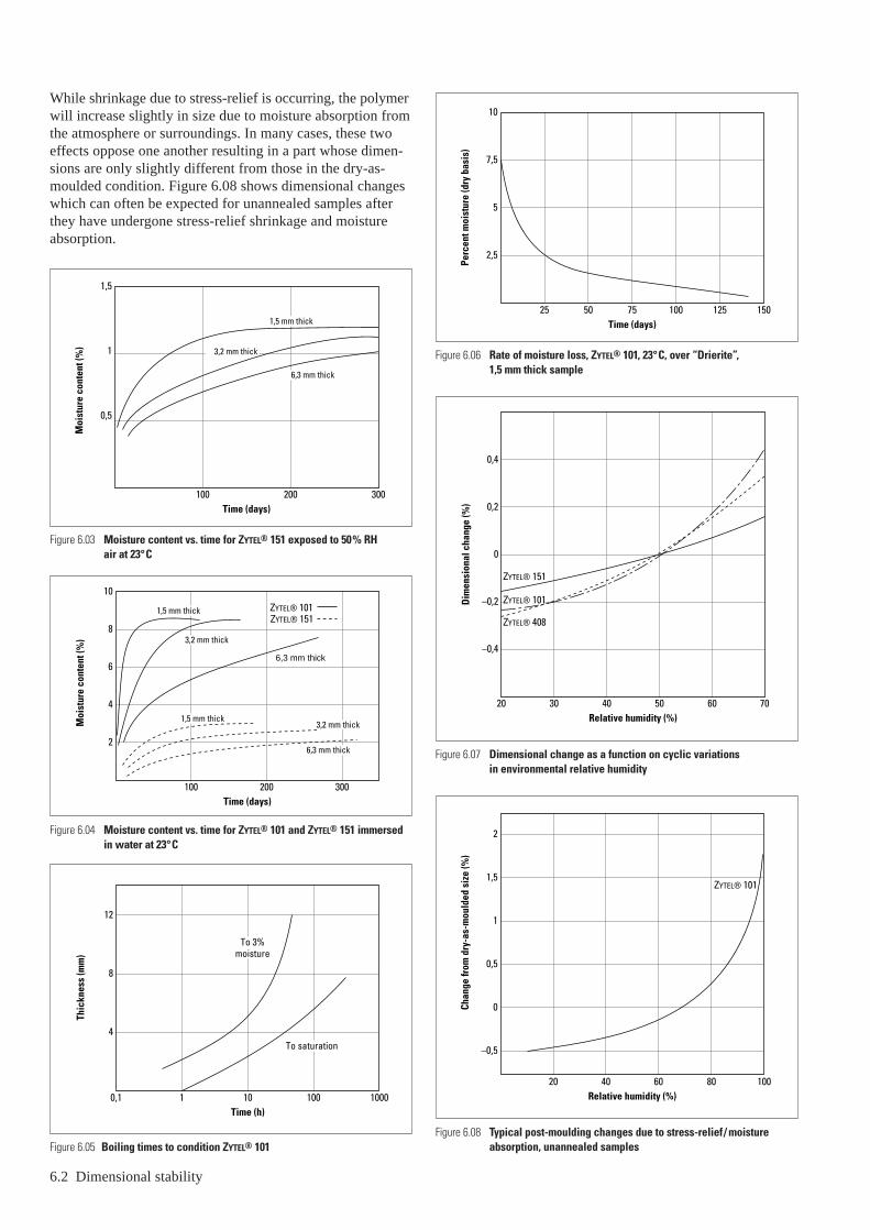
6.2 Dimensional stability
While shrinkage due to stress-relief is occurring, the polymerwill increase slightly in size due to moisture absorption fromthe atmosphere or surroundings. In many cases, these twoeffects oppose one another resulting in a part whose dimen-sions are only slightly different from those in the dry-as-moulded condition. Figure 6.08 shows dimensional changeswhich can often be expected for unannealed samples afterthey have undergone stress-relief shrinkage and moistureabsorption.
Figure 6.05 Boiling times to condition ZYTEL® 101
1,5
1
0,5
Moi
stur
e co
nten
t (%
)
Time (days)300200100
1,5 mm thick
6,3 mm thick
3,2 mm thick
10
8
6
4
2
Moi
stur
e co
nten
t (%
)
Time (days)300200100
ZYTEL® 101ZYTEL® 151
1,5 mm thick
6,3 mm thick
3,2 mm thick
1,5 mm thick
6,3 mm thick
3,2 mm thick
12
8
4
Thic
knes
s (m
m)
Time (h)10001001010,1
To 3%moisture
To saturation
Figure 6.04 Moisture content vs. time for ZYTEL® 101 and ZYTEL® 151 immersedin water at 23°C
Figure 6.03 Moisture content vs. time for ZYTEL® 151 exposed to 50% RH air at 23°C
10
7,5
5
2,5
Perc
ent m
oist
ure
(dry
bas
is)
Time (days)15075 100 1255025
0,4
0,2
0
–0,2
–0,4
Dim
ensi
onal
cha
nge
(%)
Relative humidity (%)7040 603020 50
ZYTEL® 151
ZYTEL® 101
ZYTEL® 408
2
1,5
1
0,5
0
–0,5
Chan
ge fr
om d
ry-a
s-m
ould
ed s
ize
(%)
Relative humidity (%)40 10020 8060
ZYTEL® 101
Figure 6.06 Rate of moisture loss, ZYTEL® 101, 23°C, over “Drierite”, 1,5 mm thick sample
Figure 6.07 Dimensional change as a function on cyclic variations in environmental relative humidity
Figure 6.08 Typical post-moulding changes due to stress-relief/ moistureabsorption, unannealed samples

Procedures for annealing ZYTEL® are discussed later in thisSection. A hot water treatment (also described later) not onlyadds moisture but also is an effective annealing procedure.Unlike water conditioning, relief of moulded-in stresses is anirreversible change. Once stresses are relieved by annealing,there will be no further dimensional changes from this causebelow the annealing temperature.
The above discussion explains the small dimensional changeof some mouldings that stress-relieve themselves over aperiod of time while moisture is being absorbed.
If this part is exposed to higher temperatures before thegradual change is complete, stress-relief will occur morerapidly, resulting in some shrinkage of the long dimensions.This a time-temperature phenomenon. A few minutes at150°C or several days at 70°C may produce the same effect.When stress-relief will occur in use and when dimensionalchange will affect the performance, parts should be designedto the correct size in the stress-free condition and annealedinitially. If exposed to a normal air environment after anneal-ing, the moulding will absorb moisture and behave as shownin Figure 6.09.
Note that the compensating effect on dimensional changediscussed above will not always be the case, and that it willnot prevent subsequent cycling of dimensions from variationsin relative humidity. The dimensional increase due to mois-ture absorption is predictable, but a dimensional decreasedue to stress-relief is heavily dependent on object shape andmoulding conditions. Stress-relief may cause almost nodimensional change in some cases so that the effect of waterabsorption will predominate. In other cases, stress-relief maycause a shrinkage significantly greater than the increase dueto moisture. This can only be established with certainty bytrial.
Shrinkage and dimensional stability of unreinforced ZYTEL® resinsZYTEL® nylons are crystalline plastics and generally shrinkmore from the molten to solid state than do amorphous plas-tics (e.g., acrylics, polystyrenes, etc.). This is a result of slightchanges which occur in the structure as the polymer moleculesorient themselves to achieve the most stable solid state con-figuration.
3
2
1
Incr
ease
(%)
Moisture content (%)4 102 86
ZYTEL® 101
50% HR
Figure 6.09 Change in dimensions with moisture content for ZYTEL® 101 in thestress-free (annealed) condition
50% RH
Dimensional stability 6.3
Hot mould Cold mouldMould shrinkage
Stress-relief shrink
Final part dimensions
Cavi
ty d
imen
sion
s1,5
1
0,5
Ann
ealin
g sh
rink
age
(%)
75Mould temperature (°C)
100 125 150 175
Thickness0,8 mm
1,6 mm
3,2 mm
6,4 mm
50
3
2
1
Tota
l shr
inka
ge (%
)
75Mould temperature (°C)
100 125 15050
Thickness6,4 mm
3,2 mm
1,6 mm
0,8 mm
Figure 6.12 Total shrinkage after annealing vs. mould temperature for ZYTEL® 101 NC010
Figure 6.11 Shrinkage during annealing vs. mould temperature for ZYTEL® 101 NC010
Figure 6.10 Effect of mould temperature on shrinkage dimensions
50 × 50 mm plaquesGate thickness = 1⁄2 part thicknessGate width = part thicknessAnnealed at 160°C for 1 hourTotal shrinkage = Annealing shrinkage + mould shrinkage

6.4 Dimensional stability
Owing to the rapid cooling of the polymer melt as it entersthe mould cavity, this molecular reorientation is often arrestedbefore complete stability can be achieved. As a result, smallpost-moulding changes often occur as these areas of mould-ed-in stress gradually become stabilized. The total dimen-sional change due to shrinkage is best expressed as the sumof mould shrinkage and stress-relief or annealing shrinkage.Each of these parameters is affected by mould temperature,but in opposite ways. High cavity temperatures tend to maximize mould shrinkage and minimize post mouldingshrinkage.
Low mould temperatures have just the opposite effect asshown in Figure 6.10.
Data summarizing the effect of mould temperature and partthickness on shrinkage is illustrated in Figures 6.11 and 6.12and shows that:
• As part thickness decreases at constant mould temperature,the annealing shrinkage increases.
• For any part thickness, the annealing shrinkage decreaseswith increasing mould temperature; e.g., the total dimen-sional change of the part is less.
• The combined effect of mould shrinkage and annealingshrinkage for any given part thickness is, for all practicalpurposes, independent of mould temperature.
Hence, it is easier to predict total shrinkage from initial mouldcavity dimensions than it is to predict either mould shrinkageor annealing shrinkage alone. Each of these factors will varydepending on moulding conditions and part geometry. Totalshrinkage, however, for any given part thickness is nearlyconstant.
Shrinkage and dimensional stability of reinforced ZYTEL® and MINLON® resinsThe most common reinforcement of nylons are glass fibres.Glass has a lower coefficient of thermal expansion thannylon, so that fibre reinforced parts shrink less than unrein-forced parts. However, due to the shear forces acting in thepart during injection moulding, the fibres in the part will be oriented, causing different thermal expansions in flowdirection and perpendicular.
The amount of fibres, which are oriented further depends onlocal thickness, location in the part with reference to the gateposition and several process parameters. In moulded, fibrereinforced parts shrinkages have been measured between 0,2– 0,4% in flow direction and 0,8 –1,2% in transverse direc-tion. It is very difficult to give a global rule to calculateshrinkage for a given part. Experience with similar parts isthe best reference so far, though computer analysis more andmore can help in understanding the shrinkage and warpagebehaviour of reinforced parts. To reduce warpage of rein-forced plastic parts, (a part of) the fibres can be replaced by mineral fillers (MINLON® grades). These grades normallyhave a slightly higher shrinkage in flow direction and a some-what lower shrinkage transverse. Due to the reduced differ-ential shrinkages (anisotropy), warpage of these grades canbe limited. Also here, experience with existing mouldingshelps in getting the best results for new parts.
Combined dimensional effect of mould shrinkage, stress-relief and moisture absorptionAs discussed above, it is easy to predict dimensional changesfor ZYTEL® nylons if parts are subjected to separate annealingand moisture treatments. In practice, however, most parts arenot annealed prior to use and, therefore, gradually undergostress-relief over a period of time as moisture is absorbedfrom the environment. Since two changes are occurringsimultaneously (shrinkage from stress-relief and increasedue to moisture absorption), it is difficult to predict the exactsize at any time prior to that when the part has achieved
Figure 6.14 Dimensional changes in parts of ZYTEL® 408
Figure 6.13 Dimensional changes in parts of ZYTEL® 101
100Relative humidity (%)
755025
Dim
ensi
onal
cha
nge
from
mou
ld c
avity
siz
e (%
) 1
0
–1
–2
Thickness0,8 mm
1,6 mm
3,2 mm
6,4 mm
Relative humidity (%)
Dim
ensi
onal
cha
nge
from
mou
ld c
avity
siz
e (%
)
0,5
0
–0,5
–1
–1,5
–28040
Flow
Transverse
Mould temperature 66°C.Injection pression 76 MPa.76 × 127 mm plaque (not annealed).Gate = 1⁄2 part thickness.
1⁄2 part width.If mould temperature is different from 66°C add (if lower) or substract (if higher) 0,03% per °C.If injection pressure is different from 76 MPa add 0,007% (if higher) or substract (if lower) for each MPa.
76 × 127 × 1,6 mm plaques.Mould temperature 66°C.Injection pression 76 MPa.Gate = 1⁄2 part thickness.
1⁄2 part width.

Relative humidity (%)
Dim
ensi
onal
cha
nge
from
mou
ld c
avity
siz
e (%
) 0
–0,5
–1
–1,5
8040
Flow
Transverse
100Relative humidity (%)
Dim
ensi
onal
cha
nge
from
mou
ld c
avity
siz
e (%
)
0,5
0
–0,5
–1
80604020
Flow
Transverse
100Relative humidity (%)
Dim
ensi
onal
cha
nge
from
mou
ld c
avity
siz
e (%
)
0,5
80604020
Flow
Transverse
0
–0,5
–1
Figure 6.17 Effect of humidity on dimensions ZYTEL® 77G33L (measured on 76 × 127 × 3 mm plaques)
Figure 6.16 Effect of humidity on dimensions ZYTEL® 70G30HSL (measured on 76 × 127 × 3 mm plaques)
Figure 6.15 Dimensional changes in parts of ZYTEL® 151
76 × 127 × 1,6 mm plaques.Mould temperature 66°C.Injection pression 76 MPa.Gate = 1⁄2 part thickness.
1⁄2 part width.
Dimensional stability 6.5
equilibrium with its environment. When environmental equi-librium has been achieved, part size can be accurately deter-mined if it is expressed as a function of mould cavity size.
Figures 6.13, 6.14 and 6.15 show the part dimensionsexpressed as a function of mould cavity size which can beexpected in use for three compositions, ZYTEL® 101, 408 and151. For ZYTEL® 70G30HSL and ZYTEL® 77G33L this isillustrated in Figures 6.16 and 6.17.
ZYTEL® 73G30HSL BK behaves very similar to ZYTEL®
70G30HSL, as measured on 2 mm thick testplates, 64 daysconditioned (50% RH and in water), according ISO 1110.The same test carried out on some other DuPont materialsresulted in:
Dimensional increase (%)Material Flow TransverseZYTEL® 7300 NC 50% RH 0,22 0,40
100% RH 1,20 2,00MINLON® 11C140 NC 50% RH 0,45 0,35
100% RH 1,85 1,30MINLON® 73M40HSL 50% RH 0,55 0,35
100% RH 2,00 1,30
Annealing the plates of the above test for 2 h at 120°C hardlychanged the measured values.
These figures express the combined dimensional changesdue to mould shrinkage, stress-relief or annealing shrinkageand moisture growth for a particular part thickness. Consid-ering the mould cavity dimensions as a baseline, one candetermine end-use dimensions of parts of ZYTEL® to a highdegree of accuracy. It must be remembered that these valuesare accurate only for the specific conditions of mould tem-perature, melt temperature, injection pressure and environ-mental temperature outlined in the figures. Changes in anyof these parameters can easily be compensated for, however,by using appropriate correction factors.
Moisture conditioningMoisture conditioning is used occasionally to reduce thedimensional variations of ZYTEL® due to changes in moisturecontent. This is more common for mouldings to be used inwater, where the original dimensional change is great, ratherthan in air. More frequently, moisture conditioning is usedfor two other purposes:1. to produce parts for test to determine if the expected
changes will have any effect on the performance of thepart and;
2. to increase the impact resistance of newly mouldedobjects.
Two methods of moisture conditioning ZYTEL® are describedbelow. In the first method, boiling in water, the amount of water absorbed is controlled by time and part thickness.Except at the completely saturated level, this method doesnot give a uniform distribution of water in the part as doesexposure to a constant relative humidity for a long time. It simply begins the process of distributing water throughoutthe object and hastens the time of completion. Much of theincrease in impact strength and dimensions will occur in this

6.6 Dimensional stability
procedure. Boiling in water is probably the only practicalconditioning method for most of the applications that requireconditioning. Parts can also be conditioned at temperaturesless than boiling. See Figure 6.18 for conditioning time.
The second method, which calls for use of a potassium ace-tate solution, permits uniform distribution (equivalent toequilibrium with 50% RH) of water at less than the saturationlevel. This procedure is more complex, but it is useful forpreparing test samples.
Both methods have a common disadvantage in that a longtime is required to condition thick sections, even under theaccelerated conditions. Thicknesses of 3,2 and 6,4 mmrequire about 3 and 18 hours respectively in boiling water or20 and 65 hours in potassium acetate solution for condition-ing. In greater thicknesses, incomplete conditioning may beadequate because of the extremely slow rate of furtherabsorption in use conditions.
Moisture conditioning methods available for incorporating2,8% of water in ZYTEL® 101 nylon and similar compositionsinclude:
• Boiling in water. This method is the easiest to set up, but itcannot give a true equilibrium condition. The moisture isconcentrated near the outer surface and can only redistrib-
6
4
2
5Immersion time (h)
Part
thic
knes
s (m
m)
10 15 20
100°C 77°C60°C
8
6
4
2
20Time (h)
Thic
knes
s (m
m)
40 60
Figure 6.18 Time to condition ZYTEL® 101 to 2,8% moisture
Figure 6.19 Time to absorb 2,8% moisture for ZYTEL® 101 at 120°C in potassiumacetate solution (125 g /100 ml water)
ute itself with time. It is best to put in about 3% of mois-ture, since a small amount will tend to come back out andevaporate from the surface. The required time to absorb3% by boiling is given in Figure 6.05. Test parts shouldalways be measured or weighed before and after boiling to be sure the desired dimensional change or water absorp-tion has occurred in the time selected.
• Treatment with a solution of potassium acetate in water.This method requires a heated vessel with a cover and areflux condenser. By using the ratio of 125 parts by weightof potassium acetate to 100 parts by weight of water, amaximum of 2,8% of water (equivalent to 50% RH) isabsorbed by ZYTEL® 101. Unlike the previous method,additional time beyond that required will not put in moremoisture. Conditioning in potassium acetate solution iscarried out at or near the boiling point of this solution120°C for maximum acceleration of the process. The timerequired for any thickness may be read from Figure 6.19.The problems with this procedure are the cost of potas-sium acetata and the need to maintain the solution at therequired concentration. This is an excellent method forpreparing test samples, since a true equilibrium conditionis established. It is not suitable where electrical or burningcharacteristics are to be studied because of absorption ofsmall amounts of potassium acetate on the surface.
For service in water, moisture conditioning is carried out bythe first method above, only the boiling time is lengthened toobtain completely saturated moldings (8% or more of water).The time for this process is also given in Figure 6.05. Forsections greater than 6,4 mm (1⁄4 in.), conditioning to satura-tion takes a very long time and is rarely necessary because of the extremely slow rate of absorption in use.
AnnealingWhen annealing of ZYTEL® is required, it should be done inthe absence of air, preferably by immersion in a suitable liq-uid. The temperature of the heat-treating liquid should be atleast 25°C above the temperature to which the article will beexposed in use – a temperature of 150°C is often used forgeneral annealing. This will ensure against dimensionalchange caused by uncontrolled stress-relief occurring belowthis temperature. The annealing time required is normally 5 min. per millimetre thickness. Upon removal from theheat-treating bath, the part should be allowed to cool slowlyin the absence of drafts; otherwise, surface stresses may beset up. Placing the heated article in a cardboard container isa simple way of ensuring slow, even cooling.
The choice of liquid to be used as the heat-transfer mediumshould be based on the following considerations:
• Its heat range and stability should be adequate.
• It should not attack ZYTEL®.
• It should not give off noxious fumes or vapours.
• It should not present a fire hazard.
High-boiling hydrocarbons, such as oils or waxes, may beused as a heat-transfer medium if the deposit left on the sur-face of the molded item is not objectionable, as in the case ofparts which will be lubricated in use. In DuPont Laboratories,

Primol 342 and Majoline 238-CRA from Esso as well asOndina 33 from Shell, have been used for annealing. Experi-mental work has also shown the suitability of annealing in an oven using a nitrogen atmosphere, although this doesrequire special equipment.
The heat-treating bath should be electrically heated and ther-mostatically controlled at the desired temperature. For bestthermal control, heat should be supplied through the side-walls as well as through the bottom of the vessel. A largenumber of small items is best handled by loading them into
a wire basket equipped with a lid to prevent the parts fromfloating, and immersing the basket in the bath for the requiredperiod of time.
For applications where the maximum temperature will be70°C or less, acceptable stress-relief can be obtained byimmersion in boiling water. This method also has the advan-tage that some moisture is absorbed by the ZYTEL®, thus par-tially conditioning the piece. For stress-relief, 5 min. per mmof cross section is sufficient. Longer times will be required ifthe piece is to be moisture-conditioned to or near equilibrium.
Dimensional stability 6.7


7 – Quality of fabricated parts – writing of specifications
IntroductionAn adequate system of quality control is basic to the suc-cessful fabrication or use of nylon parts. This involves, first,a verification of the identity of the nylon used. Then, thosetests must be made which are necessary to ensure that the partwas properly moulded or extruded from the resin specified.It is important that the end-user defines the quality he needs.Excessive rejects and returns under warranty can be costly if inadequate standards are set. However, excessively highstandards for any required characteristic will also raise costsunnecessarily. Exactly how the balance should be reachedhas to be worked out for each part.
A specification for moulded parts is frequently written up in three sections with the intention of: identifying the plastic,defining the quality of the plastic material and establishingpart quality.
Identification of plasticOrdinarily, a moulder need not be concerned about the iden-tity of a moulding resin; he simply uses the correct ZYTEL®
nylon composition. Of course, identification may be impor-tant if he is not careful about the labeling of regrind. Theend-user, on the other hand, may quite correctly require veri-fication of the type of nylon used in parts supplied to him.
The need for a way to identify the nylon may be met, in part,with melting point and specific gravity tests.
This particular combination of melting point and specificgravity identifies an unmodified 66 nylon. Some modifica-tions are outside these ranges and, of course, these character-istics say nothing about stabilization, lubrication, etc.
Establishment of part qualityThe part itself may be subject to appropriate quality require-ments. For convenience, these may be grouped as follows:
• Dimension and dimensional stability. Limits on the essen-tial dimensions are normally set for any moulding. In addi-tion, limits may be set after annealing in an inert oil. Thisassures that moulded-in stresses are kept to a minimum. It may occasionally be necessary to include an annealingstep in production to achieve the needed dimensional sta-bility.
• Part weight. Monitoring part weight is an easy means of checking on the uniformity of a moulding operation.Variations may indicate changes in part dimensions orproperties. Parts from different cavities in multicavitymoulds may have slight inherent differences and it isessential that these are not allowed to cloud the qualitypicture.
• End-use tests. Practical tests on moulded or extruded partsare highly recommended. These are usually, but not neces-sarily, of the impact type. Energy-to-break testing providesa means of measuring the energy required to break a partwhen it is struck in a carefully defined way – most mean-ingful if it simulates critical conditions encountered in
Quality of fabricated parts – writing of specifications 7.1
installation or service. Standard pendulum-type testers withspecial sample holders designed for the part in questionare used. The distribution of energy to break required for a particular application should be at least approximatelybased on the requirements of the application, and produc-tion parts should be tested in accordance with acceptedquality control procedures. Toughness at weld lines is oftencritical.
Go, or no-go tests using a falling ball or dart are also use-ful although they are limited in that the energy to break isnot itself measured. For example, a specification mayrequire that no more than two specimens out of 25 selectedrandomly from a given lot shall fail when struck in adefined way.
Adaptations of ASTM D746, ‘‘Brittleness Temperature ofPlastics and Elastomers by Impact’’, have also been used.Where low temperature service is involved, it may berequired that a certain percentage of parts must not be broken by a standard blow at some selected temperature.
All tests of this type, of course, require careful control of moisture content and temperature as well as the moreobvious mechanical elements.
It should also be noted that these comments on end-usetesting are intended only to make the reader aware of itspossibilities. Details have to be worked out for each casewith the help of appropriate texts on testing and qualitycontrol.
• Relative viscosity (ASTM D789). Relative viscosity, a solution viscosity related to molecular weight, is also a useful measure of the quality of a part. Toughness is a function of molecular weight. A substantial reduction of relative viscosity below that of the ZYTEL® compositionused is indicative of poor processing and of reducedtoughness. The problem is that of defining an allowablereduction. ZYTEL® 101 NC010 has a relative viscosity of about 50. We would generally hesitate to recommend a level of less than 40 for any part.
The relative viscosity cannot be used as the sole criterionof toughness or quality because other factors may be thecause of poor toughness. A part with an obvious weld linemay be brittle, but have a high viscosity.
• Appearance. Some of the factors affecting appearance arealso related to toughness and other elements of quality.Ideally, a part should be without splay, burn marks, flash,sinks, voids, contamination, unmelted particles and visibleweld lines. Some judgment is obviously required as thesecharacteristics are difficult to express on a quantitativebasis. The surface finish can be described and may beincluded.
Use of standards with numerical ratings and showingacceptable and non-acceptable parts are useful in obtainingconsistent evaluations. For example, mouldings showingthe maximum allowable colour or splay may be retained asthe basis for acceptance or rejection of production parts.


Regulatory complianceFor use in many applications, a material has either to beapproved or must meet the requirements of various govern-mental or private agencies. This is mainly to protect the user,the general public or the environment.
Besides meeting such regulations, all products and / or theirconstituents have to be listed in the different chemical inven-tories. Specific regulations exist for certain application areaslike electrical applications or applications in contact withfood.
DuPont makes sure that all materials supplied to its cus-tomers in compliance with applicable regulations for thematerial itself.
As a subscriber to the RESPONSIBLE CARE initiative,DuPont also has accepted to share information and help theproduct users to handle, process, use, recycle and dispose ofits materials safely and in an environmentally sound manner.
For selected specific application areas, DuPont hasdeveloped information which will enable the product user toobtain approvals from authorities or to certify compliancewith regulations.
These areas are:
Material classifications by Underwriters’ Laboratories, Inc.
For most of DuPont nylon resins UL ‘yellow cards’ areavailable showing flammability ratings and upper tem-perature limits for continuous use.
Compliance statements with European and non-European food contact regulations.Europe:The EU (European Union) Directive 90/128 and its subse-quent amendments plus country specific regulations whereapplicable.
USA:FDA 21 CFR 177.1500 (Food and Drug Administration of the United States Department of Health, Education andWelfare).
Canada:HPB (Health Protection Branch of Health and Welfare).
Other countries:Compliance statements can be established on request.
8 – Regulatory status
Compliance statements with European and non-European drinking water regulations.Germany:The KTW (Kunststoff-Trinkwasser-Empfehlungen) recommandation.The Netherlands:The KIWA (Keuringsinstituut voor Waterleidingartikelen)
USA:The NSF (National Sanitary Foundation).
Support information for approval of applications for foodprocessing equipment in the USAby NSF (National Foundation) or USDA (United StatesDepartment of Agriculture).
Support information for approval of application underEuropean and non-European pharmaceutical regulations.
Statements on the content of certain regulated chemicalsas required e.g. by the ‘Deutsche Dioxinverbotsverordnung’or the ‘Clean Air Act’ in the USA.
Regulations are constantly adapted as new informationbecomes available, new test methods and also issues of concern developing within public opinion.
DuPont will adapt its products to the changing market needsor develop new products to satisfy new requirements. Thesame is true for information needed to support customers forregulatory compliance of their applications.
It is impossible in the frame of this bulletin to provide up-to-date information on all grades of DuPont nylons meet-ing the various specifications. The recommendation is there-fore to consult with your DuPont representative on the bestmaterial selection for a given application in an early stage of a development.
Regulatory status 8.1

Belgique/BelgiëDu Pont de Nemours (Belgium)Antoon Spinoystraat 6B-2800 MechelenTel. (15) 44 14 11Telefax (15) 44 14 09
BulgariaServiced by Biesterfeld Interowa GmbH & Co. KG.See under Österreich.
C̆eská Republika a Slovenská RepublikaDu Pont CZ, s.r.o.Pekarska 14/268CZ-15500 Praha 5 – JinoniceTel. (2) 57 41 41 11 Telefax (2) 57 41 41 50-51
DanmarkDu Pont Danmark A/SSkjøtevej 26P.O. Box 3000DK-2770 KastrupTel. 32 47 98 00Telefax 32 47 98 05
DeutschlandDu Pont de Nemours (Deutschland) GmbHDuPont Straße 1D-61343 Bad HomburgTel. (06172) 87 0Telefax (06172) 87 27 01
EgyptDu Pont Products S.A.Bldg no. 6, Land #7, Block 1New MaadiET-CairoTel. (00202) 754 65 80Telefax (00202) 516 87 81
EspañaDu Pont Ibérica S.A.Edificio L’IllaAvda. Diagonal 561E-08029 BarcelonaTel. (3) 227 60 00Telefax (3) 227 62 00
FranceDu Pont de Nemours (France) S.A.137, rue de l’UniversitéF-75334 Paris Cedex 07Tel. 01 45 50 65 50Telefax 01 47 53 09 67
HellasRavago Plastics Hellas ABEE8, Zakythou Str.GR-15232 HalandriTel. (01) 681 93 60Telefax (01) 681 06 36
IsraëlGadot Chemical Terminals (1985) Ltd.22, Shalom Aleichem StreetIL-633 43 Tel AvivTel. (3) 528 62 62Telefax (3) 528 21 17
ItaliaDu Pont de Nemours Italiana S.r.L.Via Volta, 16I-20093 Cologno MonzeseTel. (02) 25 30 21Telefax (02) 25 30 23 06
MagyarországServiced by Biesterfeld Interowa GmbH & Co. KG.See under Österreich.
MarocDeborel Maroc S.A.40, boulevard d’Anfa – 10°MA-CasablancaTel. (2) 27 48 75Telefax (2) 26 54 34
NorgeDistrupol Nordic Niels Leuchsvei 99N-1343 EiksmarkaTel. 67 16 69 10Telefax 67 14 02 20
ÖsterreichBiesterfeld Interowa GmbH & Co. KGBräuhausgasse 3-5A-1050 WienTel. (01) 512 35 71Telefax (01) 512 35 71 12/512 35 71 31
PolskaDu Pont Poland Sp. z o.o.ul. Prosta 69PL-00-838 WarszawaTel. (022) 691 09 01Telefax (022) 691 09 10
PortugalACENYLRua do Campo Alegre, 672 – 1°P-4100 PortoTel. (2) 69 24 25/69 26 64Telefax (2) 600 02 07
RomaniaServiced by Biesterfeld Interowa GmbH & Co. KG.See under Österreich.
RussiaE.I. du Pont de Nemours & Co. Inc.Representative OfficeB. Palashevsky Pereulok 13/2SU-103 104 MoskvaTel. (095) 797 22 00Telefax (095) 797 22 01
Schweiz/Suisse/SvizzeraDolder AGImmengasse 9Postfach 14695CH-4004 BaselTel. (061) 326 66 00Telefax (061) 322 47 81Internet: www.dolder.com
SlovenijaServiced by Biesterfeld Interowa GmbH & Co. KG.See under Österreich.
Suomi/FinlandDu Pont Suomi OyBox 62FIN-02131 EspooTel. (9) 72 56 61 00Telefax (9) 72 56 61 66
SverigeDu Pont Sverige ABBox 23SE-164 93 Kista (Stockholm)Tel. (8) 750 40 20Telefax (8) 750 97 97
TürkiyeDu Pont Products S.A.Turkish Branch OfficeSakir Kesebir cad. Plaza 4No 36/7, BalmumcuTR-80700 IstanbulTel. (212) 275 33 82Telefax (212) 211 66 38
UkraineDu Pont de Nemours International S.A.Representative Office3, Glazunova StreetKyiv 252042Tel. (044) 294 96 33/269 13 02Telefax (044) 269 11 81
United KingdomDu Pont (U.K.) LimitedMaylands AvenueGB-Hemel HempsteadHerts. HP2 7DPTel. (01442) 34 65 00Telefax (01442) 24 94 63
ArgentinaDu Pont Argentina S.A.Avda. Mitre y Calle 5(1884) Berazategui-Bs.As.Tel. +54-11-4229-3468Telefax +54-11-4229-3117
BrasilDu Pont do Brasil S.A.Al. Itapecuru, 506 Alphaville06454-080 Barueri-São PauloTel. (5511) 7266 8229
Asia PacificDu Pont Kabushiki KaishaArco Tower8-1, Shimomeguro 1-chomeMeguro-ku, Tokyo 153-0064Tel. (03) 5434-6935Telefax (03) 5434-6965
South AfricaPlastamid (Pty) Ltd.43 Coleman StreetP.O. Box 59Elsies River 7480Cape TownTel. (21) 592 12 00Telefax (21) 592 14 09
USADuPont Engineering PolymersBarley Mill Plaza, Building #22P.O. Box 80022Wilmington, Delaware 19880Tel. (302) 999 45 92Telefax (302) 892 07 37
Requests for further information from countries notlisted above should be sent to:Du Pont de Nemours International S.A.2, chemin du PavillonCH-1218 Le Grand-Saconnex/GenevaTel. (022) 717 51 11Telefax (022) 717 52 00
H-56843 05.01 ® DuPont registered trademark Printed in Switzerland The miracles of science™ is a DuPont trademark
The information provided in this documentation corre-sponds to our knowledge on the subject at the date of itspublication. This information may be subject to revision asnew knowledge and experience becomes available. Thedata provided fall within the normal range of product prop-erties and relate only to the specific material designated;these data may not be valid for such material used in com-bination with any other materials or additives or in anyprocess, unless expressly indicated otherwise. The data pro-vided should not be used to establish specification limits norused alone as the basis of design; they are not intended to substitute for any testing you may need to conduct to determine for yourself the suitability of a specific material for your particular purposes. Since DuPont cannot anticipateall variations in actual end-use conditions DuPont makes nowarranties and assumes no liability in connection with anyuse of this information. Nothing in this publication is to beconsidered as a license to operate under or a recommenda-tion to infringe any patent rights.Caution: Do not use this product in medical applications involving permanent implantation in the human body. Forother medical applications see “DuPont Medical CautionStatement”, H-50102.
For further information on Engineering Polymers contact : Internet location : http ://www.dupont.com/enggpolymers/europe
Related Documents