March 2010 Prepared by: Conestoga-Rovers & Associates 3851 Shell Road, Suite 110 Richmond, British Columbia V6X 2W2 Landfill Gas Management Facilities Design Guidelines British Columbia Ministry of Environment Photo: Capital Regional District

Welcome message from author
This document is posted to help you gain knowledge. Please leave a comment to let me know what you think about it! Share it to your friends and learn new things together.
Transcript
March 2010
Prepared by:
Conestoga-Rovers & Associates3851 Shell Road, Suite 110Richmond, British ColumbiaV6X 2W2
Landfill Gas Management FacilitiesDesign Guidelines
British ColumbiaMinistry of Environment
Photo: Capital Regional District

Landfill Gas Management Facilities
Design Guidelines
Prepared pursuant to Section 7 of the Landfill Gas Management Regulation
Approved: ________David Ranson______________________ September, 2010 Director of Environmental Quality Branch Date

056417 (3) CONESTOGA-ROVERS & ASSOCIATES
TABLE OF CONTENTS Page
ACKNOWLEDGEMENTS.................................................................................................................. I
ACRONYMS AND ABBREVIATIONS............................................................................................ II
DEFINITIONS ................................................................................................................................... IV
PREFACE ........................................................................................................................................... VI
1.0 INTRODUCTION ...................................................................................................................8 1.1 REQUIREMENT TO COMPLETE A LANDFILL GAS
MANAGEMENT FACILITIES DESIGN PLAN............................................10 1.2 SUMMARY OF DESIGN AND PERFORMANCE
OBJECTIVES/STANDARDS ...........................................................................11
2.0 LANDFILL GAS BACKGROUND .....................................................................................14 2.1 POTENTIAL BENEFITS OF LANDFILL GAS ..............................................18 2.2 POTENTIAL IMPACTS OF LANDFILL GAS...............................................19 2.2.1 NUISANCE ODOURS ......................................................................................22 2.2.2 RELEASE OF GREENHOUSE GASES TO THE ATMOSPHERE...............23 2.2.3 HEALTH ISSUES AND TOXIC EFFECTS .....................................................25 2.2.4 EXPLOSIONS.....................................................................................................25 2.2.5 VEGETATION STRESS ....................................................................................26 2.3 LANDFILL GAS QUANTITY..........................................................................26 2.3.1 WASTE COMPOSITION..................................................................................30 2.3.2 MOISTURE CONTENT....................................................................................30 2.3.3 TEMPERATURE................................................................................................33 2.3.4 PH AND NUTRIENTS .....................................................................................34 2.3.5 WASTE DENSITY AND PARTICLE SIZE.....................................................34 2.3.6 LFG GENERATION MODELLING................................................................34 2.4 LANDFILL GAS QUALITY .............................................................................38
3.0 LFG COLLECTION EFFICIENCY......................................................................................43 3.1 COLLECTION EFFICIENCY STANDARDS AND OBJECTIVES ..............43 3.1.1 LFG COLLECTION ISSUES.............................................................................45 3.1.2 LFG GENERATION MODELLING ISSUES..................................................46 3.2 COLLECTION EFFICIENCY ESTIMATION METHODOLOGY...............47
4.0 OVERVIEW OF LANDFILL GAS MANAGEMENT FACILITIES DESIGN ................49 4.1 DESIGN CONSIDERATIONS .........................................................................49 4.1.1 SITE CONFIGURATION..................................................................................49 4.1.2 COVER SYSTEM DESIGN ...............................................................................50 4.1.3 LINER SYSTEM DESIGN.................................................................................52 4.1.4 MOISTURE ADDITION AND LEACHATE RECIRCULATION...............53
056417 (3) CONESTOGA-ROVERS & ASSOCIATES
4.1.5 LANDFILL OPERATIONAL CONSTRAINTS .............................................55 4.2 ACTIVE VERSUS PASSIVE COLLECTION SYSTEM DESIGN .................56 4.2.1 ACTIVE SYSTEMS ............................................................................................56 4.2.2 PASSIVE SYSTEMS...........................................................................................58 4.2.2.1 BARRIER SYSTEMS..........................................................................................61
5.0 LANDFILL GAS MANAGEMENT DESIGN....................................................................62 5.1 COLLECTION FIELD.......................................................................................64 5.1.1 HORIZONTAL COLLECTION TRENCH DESIGN CONSIDERATIONS72 5.1.2 VERTICAL EXTRACTION WELL DESIGN CONSIDERATIONS ............74 5.1.3 COLLECTION PIPING.....................................................................................82 5.1.3.1 COLLECTION PIPING DESIGN CONSIDERATIONS ...............................89 5.1.4 LEACHATE COLLECTION SYSTEM CONNECTIONS.............................96 5.1.5 MONITORING POINTS...................................................................................96 5.2 LANDFILL GAS EXTRACTION PLANT ......................................................97 5.2.1 EXTRACTION PLANT COMPONENTS.......................................................98 5.2.1.1 CONDENSATE HANDLING........................................................................104 5.2.1.2 LANDFILL GAS METERING........................................................................109 5.2.1.3 LFG EXTRACTION BLOWERS AND EQUIPMENT.................................111 5.2.2 LFG FLARES ....................................................................................................114 5.2.2.1 CANDLESTICK FLARES ...............................................................................116 5.2.2.2 ENCLOSED FLARES ......................................................................................116 5.2.3 PROCESS CONTROL SYSTEMS...................................................................122
6.0 MANAGEMENT SYSTEM COSTS...................................................................................125
7.0 BEST MANAGEMENT OPERATIONAL PRACTICES.................................................129 7.1 LFG COLLECTION FIELD ............................................................................129 7.1.1 COLLECTION FIELD MONITORING AND ADJUSTMENTS................129 7.1.1.1 AIR INTRUSION AND PRINCIPLES OF BALANCING..........................130 7.1.1.2 FIELD MONITORING....................................................................................133 7.1.2 COLLECTION FIELD MONITORING EQUIPMENT ...............................137 7.1.2.1 DIGITAL MANOMETER...............................................................................137 7.1.2.2 PORTABLE LFG ANALYZER.......................................................................137 7.1.2.3 ANCILLARY EQUIPMENT...........................................................................139 7.1.2.4 PORTABLE AIR MONITOR..........................................................................139 7.1.3 COLLECTION FIELD REPORTING.............................................................139 7.1.4 COLLECTION FIELD MAINTENANCE.....................................................141 7.1.5 LANDFILL FIRE MANAGEMENT ..............................................................141 7.2 EXTRACTION PLANT...................................................................................144 7.3 OPERATION AND MAINTENANCE MANUAL .....................................147
8.0 LANDFILL GAS MIGRATION ASSESSMENT AND CONTROL ..............................148 8.1 MIGRATION ASSESSMENT.........................................................................148 8.2 MIGRATION CONTROL...............................................................................153
9.0 HEALTH AND SAFETY....................................................................................................155
056417 (3) CONESTOGA-ROVERS & ASSOCIATES
9.1 CONFINED SPACES ......................................................................................158 9.2 LOCKOUT TAGOUT......................................................................................158 9.3 AIR MONITORING FOR DRILLING AND CONSTRUCTION WORK.159
10.0 SURFACE EMISSIONS MONITORING..........................................................................162 10.1 POINT SAMPLING.........................................................................................162 10.1.1 PORTABLE GAS DETECTORS .....................................................................162 10.1.2 STATIONARY ENCLOSURE TECHNIQUES.............................................163 10.1.3 MOBILE ENCLOSURE TECHNIQUES .......................................................164 10.2 OPTICAL REMOTE SENSING......................................................................165 10.3 TRACER TESTING..........................................................................................165 10.4 SURFACE EMISSIONS MONITORING SUMMARY ................................166
11.0 RECORD KEEPING AND REPORTING PROCEDURES.............................................167 11.1 ANNUAL REPORTING .................................................................................167
12.0 SYSTEM SHUTDOWN ......................................................................................................169 12.1 TEMPORARY SHUTDOWN .........................................................................169 12.2 PERMANENT SHUTDOWN PROCEDURES.............................................170
13.0 LANDFILL GAS UTILIZATION ......................................................................................171 13.1 LFG PRE-TREATMENT .................................................................................172 13.1.1 MOISTURE.......................................................................................................173 13.1.2 SULPHUR COMPOUNDS.............................................................................173 13.1.3 SILOXANES .....................................................................................................174 13.1.4 HALOGENATED COMPOUNDS ................................................................175 13.1.5 PRE-TREATMENT SELECTION ..................................................................176 13.2 POTENTIAL UTILIZATION APPLICATIONS ..........................................178 13.2.1 LOW-GRADE FUEL .......................................................................................179 13.2.1.1 HEATING.........................................................................................................179 13.2.1.2 BOILER FUEL ..................................................................................................180 13.2.1.3 MICROTURBINES ..........................................................................................180 13.2.2 MEDIUM-GRADE FUEL ...............................................................................181 13.2.2.1 HEATING.........................................................................................................182 13.2.2.2 RECIPROCATING GAS ENGINES ..............................................................182 13.2.2.3 GAS TURBINES...............................................................................................186 13.2.2.4 COMBINED HEAT AND POWER SYSTEMS ............................................186 13.2.3 HIGH-GRADE FUEL......................................................................................187 13.2.3.1 PIPELINE GAS ................................................................................................187 13.2.3.2 COMMERCIAL SALE OF CARBON DIOXIDE..........................................190 13.2.3.3 CHEMICAL PRODUCTS GENERATION...................................................191 13.2.3.4 FUEL CELLS ....................................................................................................191 13.2.3.5 FUEL FOR VEHICLES....................................................................................192 13.3 UTILIZATION SELECTION FACTORS ......................................................192
REFERENCES...................................................................................................................................200

056417 (3) CONESTOGA-ROVERS & ASSOCIATES
LIST OF FIGURES
FIGURE 2.1 METHANE EMISSIONS BY SOURCE
FIGURE 2.2 B.C. WASTE GREENHOUSE GAS EMISSION (2006)
FIGURE 2.3 POTENTIAL LFG IMPACTS
FIGURE 2.4 GREENHOUSE PHENOMENON
FIGURE 2.5 LANDFILL GAS GENERATION PATTERNS (TYPICAL)
FIGURE 2.6 TYPICAL PROFILES FOR LFG GENERATION
FIGURE 4.1 PASSIVE SYSTEMS FOR LFG MIGRATION
FIGURE 5.1 VERTICAL EXTRACTION WELL, ABOVE GROUND (TYPICAL)
FIGURE 5.2 VERTICAL EXTRACTION WELL, BELOW GROUND (TYPICAL)
FIGURE 5.3 HORIZONTAL COLLECTION TRENCH CROSS-SECTIONS (TYPICAL)
FIGURE 5.4 HORIZONTAL COLLECTION TRENCH DETAIL
FIGURE 5.5 LFG COLLECTION SYSTEM LAYOUTS
FIGURE 5.6 SINGLE AND DUEL LANDFILL GAS HEADER CROSS-SECTIONS
FIGURE 5.7 LANDFILL GAS HEADER CLEANOUT (TYPICAL – OPTIONAL)
FIGURE 5.8 CONDENSATE TRAP CHAMBER (TYPICAL)
FIGURE 5.9 CONDENSATE PUMP STATION (TYPICAL)
FIGURE 5.10 CONDENSATE TANK (TYPICAL)
FIGURE 5.11 PROCESS SCHEMATIC (TYPICAL) LFG COLLECTION AND
CONTROL SYSTEM
FIGURE 5.12 LFG CONTROL PLANT COMPOUND
FIGURE 5.13 MOISTURE KNOCKOUT (TYPICAL)
FIGURE 5.14 LANDFILL GAS CANDLESTICK FLARE
FIGURE 5.15 ENCLOSED LANDFILL GAS FLARE
FIGURE 6.1 CONCEPTUAL COST VERSUS COLLECTION EFFICIENCY
FIGURE 8.1 MULTILEVEL GAS PROBE DETAIL (TYPICAL)
FIGURE 13.1 LFG PRE-TREATMENT FOR UTILIZATION TECHNOLOGY
SELECTION
FIGURE 13.2 GAS ENGINE POWER PLANT (TYPICAL)
FIGURE 13.3 HIGH-GRADE LFG FUEL SYSTEM (TYPICAL)
FIGURE 13.4 LFG UTILIZATION DEVELOPMENT PROCESS
056417 (3) CONESTOGA-ROVERS & ASSOCIATES
LIST OF PHOTOS
PHOTO 1 VERTICAL LANDFILL GAS EXTRACTION WELLHEAD IN ABOVE
GROUND CHAMBER
PHOTO 2 HORIZONTAL LANDFILL GAS COLLECTION TRENCH
INSTALLATION
PHOTO 3 VERTICAL LANDFILL GAS EXTRACTION WELL DRILLING AND
INSTALLATION
PHOTO 4 TYPICAL VERTICAL LANDFILL GAS EXTRACTION WELLHEAD IN
BELOW GROUND CHAMBER
PHOTO 5 TYPICAL VERTICAL LANDFILL GAS EXTRACTION WELL STICK-UP
PHOTO 6 VERTICAL LANDFILL GAS EXTRACTION WELLS IN ABOVE
GROUND CHAMBERS
PHOTO 7 CONDENSATE TRAP MANHOLE
PHOTO 8 INSIDE OF LANDFILL GAS ANALYZER
PHOTO 9 LANDFILL GAS BLOWER AND CONTROL VALVES
PHOTO 10 SKID-MOUNTED LANDFILL GAS FLARE PACKAGE
PHOTO 11 LANDFILL GAS BLOWER SHELTER AND ENCLOSED FLARE
PHOTO 12 REFRACTORY LINING FOR ENCLOSED LANDFILL GAS FLARE
PHOTO 13 SILOXANE DEPOSITS ON TURBINE BLADE (U.S. EPA, 2006)
PHOTO 14 ENCLOSED FLARE AND HEADER TO LANDFILL GAS UTILIZATION
FACILITY
PHOTO 15 LANDFILL GAS CATERPILLAR RECIPROCATING ENGINES
PHOTO 16 EXAMPLE OF A JENBACHER ENGINE (CONESTOGA ROVERS &
ASSOCIATES, 2004)
056417 (3) CONESTOGA-ROVERS & ASSOCIATES
LIST OF TABLES
TABLE 1.1 SUMMARY OF DESIGN AND PERFORMANCE
OBJECTIVES/STANDARDS
TABLE 2.1 LANDFILL GAS COMPOUNDS
TABLE 2.2 SATURATION WATER CONTENT OF LFG AT AMBIENT PRESSURE
TABLE 2.3 CYCLIC AND LINEAR SILOXANES
TABLE 2.4 TYPICAL PARAMETERS OF LFG
TABLE 5.1 SUMMARY COMPARISON OF LFG COLLECTION PIPING
ARRANGEMENTS
TABLE 5.2 COLLECTION PIPING DESIGN RECOMMENDATIONS
TABLE 5.3 SUMMARY OF LFG EXTRACTION PLANT DESIGN
CONSIDERATIONS
TABLE 6.1 BUDGET YARDSTICKS FOR LFG MANAGEMENT SYSTEM
COMPONENTS
TABLE 6.2 BUDGET YARDSTICKS FOR LFG COLLECTION SYSTEMS
TABLE 7.1 COMMON LFG COLLECTION SYSTEM AND FUEL RECOVERY
ISSUES
TABLE 8.1 GUIDANCE ON TYPICAL OFF-SITE MONITORING GAS PROBE
SPACING
TABLE 9.1 EXPLOSIVE LIMITS OF METHANE GAS
TABLE 9.2 COMBUSTIBLE GAS ACTION LEVELS FOR NON-CONFINED SPACE
READINGS
TABLE 9.3 COMBUSTIBLE GAS ACTION LEVELS FOR OFF-SITE BOREHOLE
READINGS
TABLE 9.4 OXYGEN ACTION LEVELS FOR ALL READINGS
TABLE 10.1 SUMMARY OF SURFACE EMISSIONS MONITORING
TECHNOLOGIES
TABLE 13.1 DESCRIPTION OF BIOGAS FUEL GRADES
TABLE 13.2 TYPICAL PRICE STRUCTURE FOR LFG UTILIZATION
TECHNOLOGIES

056417 (3) CONESTOGA-ROVERS & ASSOCIATES
LIST OF APPENDICES
APPENDIX A LANDFILL GAS MANAGEMENT FACILITIES DESIGN TEMPLATE
APPENDIX B LFG COLLECTION EFFICIENCY ESTIMATION SAMPLE
CALCULATIONS
LIST OF EQUATIONS
EQUATION 1 SCHOLL CANYON MODEL
EQUATION 2 COLLECTION EFFICIENCY (CE)
EQUATION 3 NORMALIZED AVERAGE COLLECTED FLOW RATE OF LFG (Qc)
EQUATION 4 AVERAGE MEASURED LFG FLOW RATE (Qa)
056417 (3) i CONESTOGA-ROVERS & ASSOCIATES
ACKNOWLEDGEMENTS
This Guideline has been prepared by Conestoga-Rovers & Associates on behalf of the British Columbia Ministry of Environment (MOE) to support the MOE in the implementation of the Landfill Gas Management Regulation (BC MOE, 2008), and specifically in the completion of landfill gas management facilities design. Natalia Kukleva, Frank Rhebergen, Rob Dalrymple, Jack Bryden, and Allan Leuschen of the MOE provided insight and support in developing the landfill gas management facilities design guidelines and interpreting the Landfill Gas Management Regulation throughout this process. A peer review of the Guideline has been conducted by experts in the field of landfill gas collection and solid waste management, and the results of the peer review have been considered for incorporation into this final Guideline. Chuck Smith of CH2MHill, Lynn Belanger of the City of Vancouver, Greg Huculak of GNH Engineering, Barry Rogers of LFG Technologies, Helmut Blanken of the Regional District of Nanaimo, Andy Heffel; Kenneth Kruszynski; Eric Peterson; and Eric Sonsthagen of SCS Engineers, and Ali Abedini of Sperling Hansen Associates provided review comments.
056417 (3) ii CONESTOGA-ROVERS & ASSOCIATES
ACRONYMS AND ABBREVIATIONS
Btu/scfm British thermal units per standard cubic foot per minute
CE collection efficiency
CFCs chlorofluorocarbons
cfm cubic foot per minute
CH4 methane
CNG compressed natural gas
CO2 carbon dioxide
CO2e carbon dioxide equivalent
CRA Conestoga-Rovers & Associates
FID flame ionization detector
FTIR Fourier transform infrared spectroscopy
GHG greenhouse gas
Guideline Landfill Gas Management Facilities Design Guidelines
H2S hydrogen sulphide
HDPE high density polyethylene
hp horsepower
in WC inches of water column
kJ kilojoule
km kilometre
kPa kilopascal
kt kilotonne
kW kilowatt
L litre
LEL lower explosive limit
LFG landfill gas
LNG liquefied natural gas
m3 cubic metre
m metre
mg milligram
MJ megajoule
MCC motor control centre
MOE British Columbia Ministry of Environment
MSW municipal solid waste
mol mole

056417 (3) iii CONESTOGA-ROVERS & ASSOCIATES
ACRONYMS AND ABBREVIATIONS
MW megawatt
N2O nitrous oxide
nm nanometre
NMOCs non-methane organic compounds
NSPS New Source Performance Standards
O2 oxygen
O&M operations and maintenance
PLC programmable logic controller
ppm parts per million
ppmv parts per million by volume
psi pounds per square inch
PVC polyvinyl chloride
SCADA supervisory control and data acquisition systems
SSO source-separated organics
TDL tunable diode laser spectroscopy
TLV threshold limit value
UEL upper explosive limit
USEPA United States Environmental Protection Agency
VFD variable frequency drive
VOCs volatile organic compounds
% v/v percent by volume
056417 (3) iv CONESTOGA-ROVERS & ASSOCIATES
DEFINITIONS
director A person employed by the government and designated in writing by the minister as a director of waste management or as an acting, deputy, or assistant director of waste management.
environmental management act
The British Columbia Environmental Management Act, SBC 2003, Chapter 23, Assented to October 23, 2003.
guidelines The most recent edition of landfill gas management guidelines approved by the director and published on a publicly accessible website maintained by or on behalf of the MOE.
landfill gas A mixture of gases generated by the decomposition of municipal solid waste.
LFG generation assessment calculation tool
A spreadsheet model developed to calculate the tonnes of methane generated by a landfill to assess the requirement to install a landfill gas management facility.
LFG generation assessment calculation tool for annual reporting
A spreadsheet model developed to calculate the tonnes of methane generated by a landfill to assess a landfill gas management facility’s collection efficiency in annual reports.
municipal solid waste As defined by the Environmental Management Act, waste that originates from residential, commercial, institutional, demolition, land clearing, or construction sources, or waste specified by a director to be included in a waste management plan.
qualified professional In relation to a duty or function under the Landfill Gas Management Regulation, a professional who: is an applied scientist or technologist specializing in a
particular applied science or technology is registered in British Columbia with a professional
organization's code of ethics and is subject to disciplinary action by that organization
through suitable education, experience, accreditation, and knowledge respecting solid waste and landfill gas management, may reasonably be relied on to provide advice within their area of expertise, which area of expertise is applicable to the duty or function
regulated landfill site A landfill site that:
has 100,000 tonnes or more of municipal solid waste in place

056417 (3) v CONESTOGA-ROVERS & ASSOCIATES
receives 10,000 or more tonnes of municipal solid waste for disposal into landfill site in any calendar year after 2008
regulation British Columbia Landfill Gas Management Regulation,
Order in Council No. 903, Ordered and Approved December 8, 2008.
056417 (3) vi CONESTOGA-ROVERS & ASSOCIATES
PREFACE
This Guideline has been developed for the British Columbia (BC) Ministry of Environment (MOE) to provide guidance for the design of landfill gas (LFG) management facilities at municipal solid waste (MSW) landfills in BC that are estimated to generate greater than 1,000 tonnes of methane per year based on the Landfill Gas Generation Assessment and Report prepared for such landfills. This is a requirement under the British Columbia Landfill Gas Management Regulations (Regulation), approved and ordered on December 8, 2008. This Guideline is based on technical experience in the field of LFG management facilities design and best management practices for LFG management facilities operations. The intent of this document is to provide guidance for the design, installation, and operation of robust and efficient landfill gas management systems that address greenhouse gas (GHG) emissions, odour emissions, and health and safety. A review of LFG management regulations worldwide has been conducted to guide the compilation of this document. As LFG management is a distinctly site-specific issue, the intention of this document is not to prescribe in detail the design basis for every possible set of landfill configurations and conditions. However, this document does prescribe performance standards that are intended to convey the MOE's goal of having high-efficiency landfill gas collection and combustion systems developed and installed at BC landfills. Note that this document acknowledges the challenges of improving the efficiency of existing LFG collection systems, but an assessment should be made of current collection efficiency for these existing LFG collection systems with a view towards optimizing the capture of LFG through design and operational changes. This Guideline is specifically not intended to constrain designers from providing innovative LFG management systems, or to prescribe in detail how design should be undertaken. It is recognized that LFG management design continues to evolve and new approaches will become available over time; it is also recognized that practitioners subscribe to design preferences and approaches that may differ. The intent of this document is to ensure that systems operate according to specific performance standards, supplemented with design criteria at the broad level, such that practitioners of design may engage in their work with a common understanding of the performance expectations and standards as prescribed by the BC MOE.

056417 (3) vii CONESTOGA-ROVERS & ASSOCIATES
This Guideline must be used by landfill owners, operators, and qualified professionals in the preparation of LFG management facilities design in accordance with the Landfill Gas Management Regulation. To achieve the required design and performance standards/objectives specified within this Guideline, it is expected that owners and operators will need to treat the landfill as a living organism; all systems related to the operations of the landfill must be integrated and treated as one complex system when designing a LFG management system according to the performance standards identified in this document. The photos within this Guideline have been provided for general illustration purposes only. The guidance and the requirements provided in the text supersede all photos.
056417 (3) 8 CONESTOGA-ROVERS & ASSOCIATES
1.0 INTRODUCTION
This Landfill Gas Management Facilities Design Guidelines (Guideline) must be used by landfill owners, operators, and qualified professionals. It provides the user with guidance to design landfill gas (LFG) management facilities as required by the British Columbia (BC) Landfill Gas Management Regulation (Regulation), approved and ordered on December 8, 2008. This Guideline has been organized into the following sections: Section 1.0 provides an introduction to this Guideline, describes the LFG
Management Regulation requirements to complete a LFG management facilities design plan, and provides a summary of the design and performance standards within this Guideline.
Section 2.0 provides a description of landfill gas, landfill gas composition and
quantity, and the potential beneficial uses and impacts of landfill gas. Section 3.0 provides a description of performance standards as they relate to LFG
collection. Section 4.0 provides an overview of LFG management facilities design and discusses
design considerations. Section 5.0 provides guidance for the design of LFG management facilities and
includes a discussion of each component. Section 6.0 discusses the costs associated with LFG management facilities. Section 7.0 discusses the best management practices for operating a LFG
management system and maximizing LFG collection. Section 8.0 provides a description of LFG migration assessment and control. Section 9.0 discusses the hazards associated with LFG management systems and
health and safety aspects of constructing and operating a LFG management facility.
Section 10.0 provides a discussion of surface emissions monitoring technologies.

056417 (3) 9 CONESTOGA-ROVERS & ASSOCIATES
Section 11.0 describes the record keeping and reporting requirements for LFG management facilities operations.
Section 12.0 describes the procedures and contingency measures for LFG management
facilities temporary shutdown, and permanent shutdown procedures and reporting requirements.
Section 13.0 provides a description of LFG utilization technologies and gas pre-
treatment options. This document is intended to present best management practice as it relates to the design, construction, and operation of LFG management systems. It provides design specification and operational guidance in this context, with the expectation that such guidance is applicable to the vast majority of landfills in BC. It is recognized and understood that LFG management systems must reflect specific site conditions and other constraints, but the best management practices should be incorporated into the overall LFG design and operation. This document is intended to specify these practices. While the design activity must be flexible, there are reasonable bounds and guidance that can be provided to a knowledgeable industry to provide consistency in the outcome of LFG management systems; this document is intended to convey such information. In addition, a number of performance standards are embedded within this document. These performance standards are bolded and provided in text boxes for easy reference. It is the BC MOE's intention to encourage the development of high-quality LFG management systems to address the overall concerns of greenhouse gas (GHG) emissions, odour control, and health and safety. The performance standards identified in this document have been compared against regulations for LFG management in a number of other jurisdictions around the world in order to develop a comprehensive Guideline that sets achievable yet aggressive performance standards. Having worked in a number of jurisdictions around the world in the area of LFG management, the authors of this document believe that such performance standards are appropriate and consistent with the BC MOE's overall objectives and must be adhered to for all LFG management systems where the landfill is subject to the conditions of the Regulation.
056417 (3) 10 CONESTOGA-ROVERS & ASSOCIATES
1.1 REQUIREMENT TO COMPLETE A LANDFILL GAS MANAGEMENT FACILITIES DESIGN PLAN
The Regulation applies to landfills that accept municipal solid waste (MSW) on or after January 1st, 2009. A landfill is termed a regulated landfill site under the Regulation if it has 100,000 tonnes or more of MSW in place or receives 10,000 or more tonnes of MSW in any calendar year after 2008. Regulated landfills are required to complete a LFG generation assessment report to be submitted to the director by January 1, 2011. A guidance document entitled, "Landfill Gas Generation Assessment Procedure Guidance Report" is provided on the BC MOE's website, as well as a LFG generation estimation tool (British Columbia, Landfill Gas Management Regulation. Available at: http://www.env.gov.bc.ca/epd/codes/landfill_gas/index.htm) These documents provide a procedure for modelling the LFG generation rate at MSW landfills in BC. The estimated LFG generation rate is then compared to the 1,000 tonnes of methane (CH4) per year threshold for triggering the necessity to install a LFG management system as per the Regulation. A LFG management facilities design plan must be prepared for all regulated landfills that are estimated to generate 1,000 tonnes or more of CH4 in the calendar year immediately preceding the calendar year of the LFG generation assessment. The design plan must be prepared by a qualified professional in accordance with this Guideline. As outlined in the Regulation, the design plan shall include the following: • A description of existing or planned methods, management practices, and processes
for LFG management at the landfill site
• A plan for the installation, operation, and maintenance of landfill gas management facilities at the landfill site, including a contingency plan for disruption in LFG management for scheduled or emergency maintenance or replacement of LFG management facilities
• Recommendations for optimizing LFG management at the landfill site
• Certification by the qualified professional that the plan was prepared in accordance with this Guideline
• All additional information as required in this Guideline
• Any other information requested in writing by the director
056417 (3) 11 CONESTOGA-ROVERS & ASSOCIATES
The LFG management facilities design plan shall be submitted to the director no later than January 1, 2012. Appendix A provides a report template to be used for the preparation of the design plan. A LFG management facilities design plan prepared for the landfill site before January 1, 2009, may be submitted to the director in substitution for the LFG management facilities design plan required by the Regulation if a qualified professional certifies in writing that the LFG management facilities design plan meets all of the requirements outlined above, in addition to any other information requested by the director. Further to the Regulation, if a LFG management facilities design plan exists for a regulated landfill with a LFG management system in place, a qualified professional must also certify in writing that the current system is complying with the design and performance standards outlined in this Guideline (See Section 1.2). If any of the design or performance standards are not currently being met, future plans to attempt to reach these standards must be provided in writing by a qualified professional. Irrespective of this Guideline, it should be noted that there are other potential design requirements that must be observed. This document has been compiled in general accordance with CAN/CGA-B105-M93, the Canadian Gas Association's "Code for Digester Gas and Landfill Gas Installations." This standard and all other applicable standards should be consulted for specific information and requirements when engaging in the design of LFG management systems. Practitioners should seek to remain abreast of additional design requirements as they emerge. 1.2 SUMMARY OF DESIGN AND PERFORMANCE
OBJECTIVES/STANDARDS
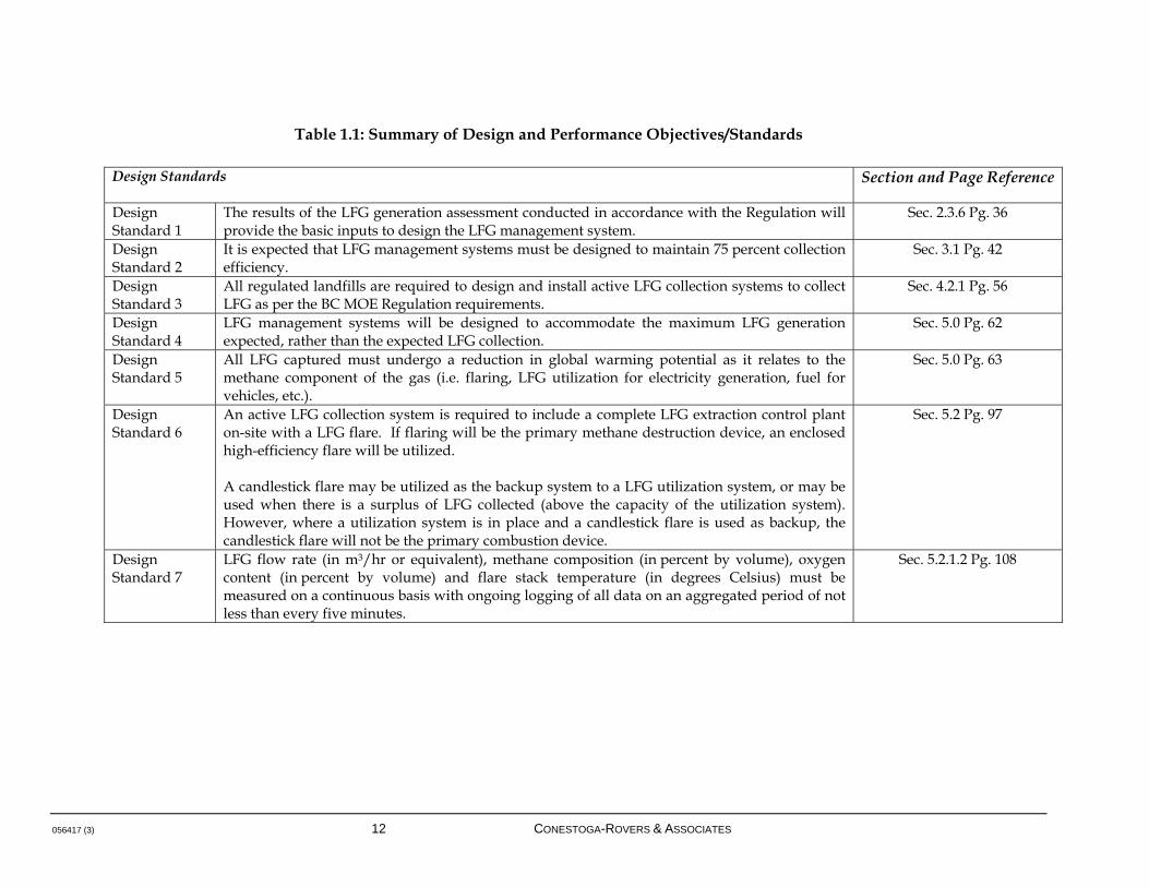
The following table summarizes the design and performance objectives/standards listed within this Guideline to provide landfill owners/operators with a clear understanding of the requirements of a LFG management system if the landfill is subject to the conditions of the Regulation.
056417 (3) 12 CONESTOGA-ROVERS & ASSOCIATES
Table 1.1: Summary of Design and Performance Objectives/Standards
Design Standards
Section and Page Reference
Design Standard 1
The results of the LFG generation assessment conducted in accordance with the Regulation will provide the basic inputs to design the LFG management system.
Sec. 2.3.6 Pg. 36
Design Standard 2
It is expected that LFG management systems must be designed to maintain 75 percent collection efficiency.
Sec. 3.1 Pg. 42
Design Standard 3
All regulated landfills are required to design and install active LFG collection systems to collect LFG as per the BC MOE Regulation requirements.
Sec. 4.2.1 Pg. 56
Design Standard 4
LFG management systems will be designed to accommodate the maximum LFG generation expected, rather than the expected LFG collection.
Sec. 5.0 Pg. 62
Design Standard 5
All LFG captured must undergo a reduction in global warming potential as it relates to the methane component of the gas (i.e. flaring, LFG utilization for electricity generation, fuel for vehicles, etc.).
Sec. 5.0 Pg. 63
Design Standard 6
An active LFG collection system is required to include a complete LFG extraction control plant on-site with a LFG flare. If flaring will be the primary methane destruction device, an enclosed high-efficiency flare will be utilized. A candlestick flare may be utilized as the backup system to a LFG utilization system, or may be used when there is a surplus of LFG collected (above the capacity of the utilization system). However, where a utilization system is in place and a candlestick flare is used as backup, the candlestick flare will not be the primary combustion device.
Sec. 5.2 Pg. 97
Design Standard 7
LFG flow rate (in m3/hr or equivalent), methane composition (in percent by volume), oxygen content (in percent by volume) and flare stack temperature (in degrees Celsius) must be measured on a continuous basis with ongoing logging of all data on an aggregated period of not less than every five minutes.
Sec. 5.2.1.2 Pg. 108
056417 (3) 13 CONESTOGA-ROVERS & ASSOCIATES
Table 1.1 (cont'd): Summary of Design and Performance Objectives/Standards
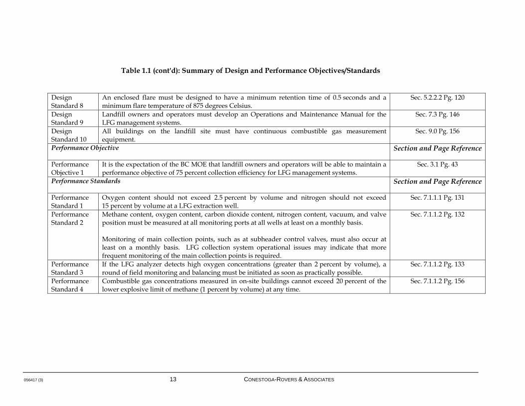
Design Standard 8
An enclosed flare must be designed to have a minimum retention time of 0.5 seconds and a minimum flare temperature of 875 degrees Celsius.
Sec. 5.2.2.2 Pg. 120
Design Standard 9
Landfill owners and operators must develop an Operations and Maintenance Manual for the LFG management systems.
Sec. 7.3 Pg. 146
Design Standard 10
All buildings on the landfill site must have continuous combustible gas measurement equipment.
Sec. 9.0 Pg. 156
Performance Objective
Section and Page Reference
Performance Objective 1
It is the expectation of the BC MOE that landfill owners and operators will be able to maintain a performance objective of 75 percent collection efficiency for LFG management systems.
Sec. 3.1 Pg. 43
Performance Standards
Section and Page Reference
Performance Standard 1
Oxygen content should not exceed 2.5 percent by volume and nitrogen should not exceed 15 percent by volume at a LFG extraction well.
Sec. 7.1.1.1 Pg. 131
Performance Standard 2
Methane content, oxygen content, carbon dioxide content, nitrogen content, vacuum, and valve position must be measured at all monitoring ports at all wells at least on a monthly basis. Monitoring of main collection points, such as at subheader control valves, must also occur at least on a monthly basis. LFG collection system operational issues may indicate that more frequent monitoring of the main collection points is required.
Sec. 7.1.1.2 Pg. 132
Performance Standard 3
If the LFG analyzer detects high oxygen concentrations (greater than 2 percent by volume), a round of field monitoring and balancing must be initiated as soon as practically possible.
Sec. 7.1.1.2 Pg. 133
Performance Standard 4
Combustible gas concentrations measured in on-site buildings cannot exceed 20 percent of the lower explosive limit of methane (1 percent by volume) at any time.
Sec. 7.1.1.2 Pg. 156

056417 (3) 14 CONESTOGA-ROVERS & ASSOCIATES
2.0 LANDFILL GAS BACKGROUND
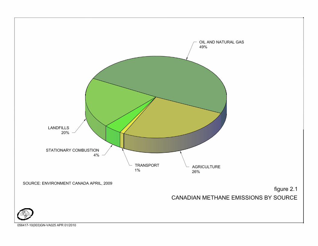
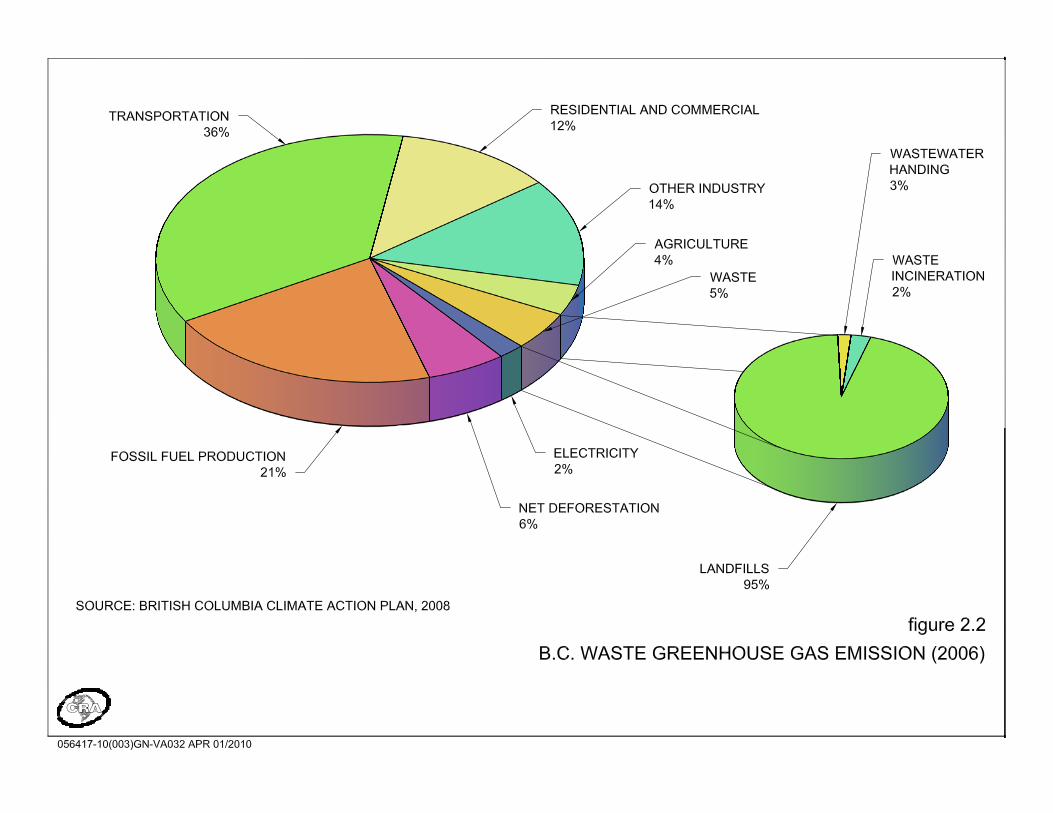
LFG is produced at landfill sites containing decomposable organic wastes. The major constituents of LFG are methane and carbon dioxide, which are by-products of the biological decomposition of organic material. Trace concentrations of a variety of other compounds may also be present in LFG, including hydrogen sulphide, mercaptans, and volatile organic compounds, which can create nuisance odours, degrade air quality, and result in adverse health effects. Generally, the amount and character of the organic waste in a landfill directly affects the quality and quantity of LFG that will be generated; other environmental factors further play a part in dictating LFG generation. The methane component of LFG is a potential energy resource, but is also a potential explosion hazard, and is accepted as a GHG contributing to global warming; the carbon dioxide component of LFG is generally regarded as being biogenic in origin and is thus not considered an additional GHG emission. To emphasize the importance of methane emissions from landfills, methane is considered to be approximately 25 times more heat absorptive than carbon dioxide on a mass basis with a time horizon of 100 years (IPCC, 2007). LFG is one of the major anthropogenic sources of methane emissions to the atmosphere in Canada, accounting for about 20 percent of the nation's total methane emissions in 2007 (see Figure 2.1). Methane emissions produced by the decomposition of biomass in MSW were responsible for 82 percent of the emissions from the waste sector, which also included wastewater handling and waste incineration. Emissions from MSW landfills increased by 16 percent from 1990 to 2007, despite an increase in LFG capture and combustion of 71 percent over the same period. The quantity of methane captured at MSW landfills for flaring or combustion for energy recovery purposes in 2007 amounted to 28 percent of the total generated emissions from this source, as compared to 21 percent in 1990 (Environment Canada, 2009). In BC, GHG emissions from waste accounted for approximately 5 percent of the province’s GHG emissions in 2006. GHG emissions from landfills accounted for approximately 95 percent of the emissions from BC’s waste sector, which also includes wastewater handling and waste incineration (see Figure 2.2) (LiveSmart BC, 2008). Approximately 330 kilotonnes (kt) of CH4 (or 6,930 kt carbon dioxide equivalent [CO2e]) were captured by the 65 LFG collection systems operating in Canada in 2007. Of the total amount of methane collected in 2007, 50 percent (165 kt) was utilized for various energy purposes and the remainder of the methane gas was flared. Based on the
056417 (3) 15 CONESTOGA-ROVERS & ASSOCIATES
information available for 2007, of these 65 sites, 14 sites utilized the captured methane, 36 sites flared the captured gas, and 15 sites employed both utilization and flaring practices (Environment Canada, 2009). As of early 2010, there are seven LFG collection systems in British Columbia and LFG is being utilized at four of these sites and flared at three.
056417 (3) 18 CONESTOGA-ROVERS & ASSOCIATES
In 2007, the Province of BC enacted the Greenhouse Gas Reduction Targets Act, committing BC to reducing BC’s GHG emissions to 33 percent below 2007 levels by 2020 and to 80 percent below 2007 levels by 2050. The BC Climate Action Plan identified actions taken in all sectors to reduce GHG emissions, one of which is the introduction of the Landfill Gas Management Regulation. In the past, LFG management systems were designed as odour control systems. Regulatory and GHG concerns have now led to the development of LFG management systems that collect high volumes of LFG for combustion. Additionally, LFG utilization is practiced at landfills in Europe, North America, and other parts of the world, especially as economic and technical factors continue to evolve and improve the viability of these projects. In order to utilize LFG, collection systems that operate at higher recovery efficiency must be developed, and thus the experience and knowledge to develop these systems continues to develop and gain traction in the industry. 2.1 POTENTIAL BENEFITS OF LANDFILL GAS
The primary direct benefits of managing LFG are the control of potential adverse impacts and the reduction of liability for the site owner. Numerous LFG control projects indicate that nuisance odours, explosion concerns, and toxic hazards can be effectively mitigated by implementing LFG management systems. Methods for managing LFG are presented in more detail in Section 5.0. The GHG benefit of LFG management projects has been described above. LFG has numerous additional beneficial uses that stem primarily from the energy content of its methane component. Many of the technologies for utilization of LFG are now well established and have proven to be economically feasible given suitable site conditions and access to markets. Electricity generation from LFG is the most prevalent utilization option, but refining of LFG to pipeline-quality natural gas is becoming more common, as is the formulation of fuel for vehicles. More information on LFG utilization and beneficial uses are provided in Section 13.0. However, as earlier noted, beneficial use of LFG is highly dependent on the quality and efficiency of the LFG collection system from an economics standpoint, and thus it is important to ensure that gas collection systems are correctly designed and installed to provide a consistent and steady supply of LFG to the utilization facility. Operations are also a key component of this equation, as operation of even a well-designed and constructed LFG management system can at times result in poor gas supply if operations are not performed in a manner consistent with the objective of fuelling the plant.

056417 (3) 19 CONESTOGA-ROVERS & ASSOCIATES
Utilization of LFG to produce energy has the added benefit of offsetting consumption of fossil fuels that would be required to produce an equivalent amount of energy. LFG is a relatively "clean burning" fuel when compared to most other fuels. This benefit is strongest in jurisdictions where the grid-connected electricity is dominated by "dirtier" energy, such as coal. In BC, where a high proportion of electricity generation is related to hydroelectric plants (which are considered to be null in terms of GHG emissions), the relative benefit, or emission intensity, is somewhat smaller than in other areas of Canada or the United States. Emission intensity, measured as tonnes of carbon dioxide equivalent emissions per Megawatt-hour (tonne CO2 eq/MWh), represents the quantity of equivalent carbon dioxide emissions (1 tonne CO2 eq) produced per Megawatt-hour of electricity generated. In 2008, BC's emission intensity for electricity generation was 0.02 tonnes CO2 eq/MWh, one of the lowest in Canada. In comparison, Alberta had the highest national emission intensity in 2008 with 0.88 tonnes CO2 eq/MWh, due to an electricity generation system that is predominantly coal-based (Environment Canada, 2010). However, the implementation of additional electrical generation capacity is a clear benefit, especially when coupled with the emissions reductions achieved through methane destruction. As economic incentives for LFG utilization continue to evolve, the viability of such projects will continue to improve. 2.2 POTENTIAL IMPACTS OF LANDFILL GAS
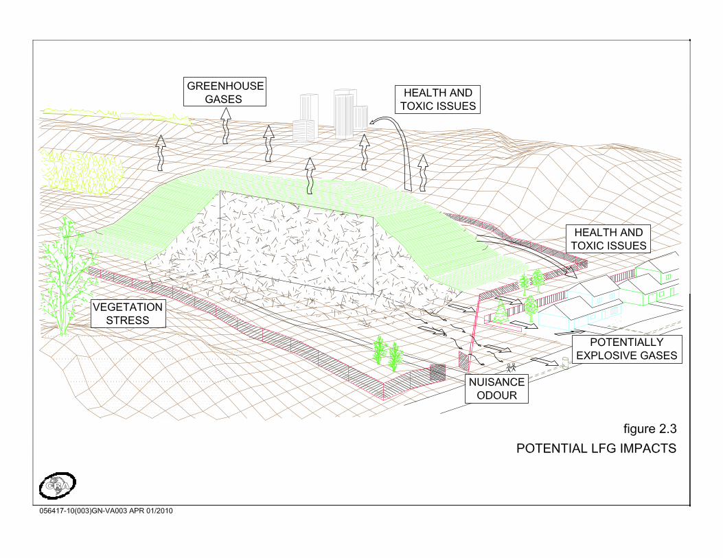
Pressure is generally accumulated within a landfill as a direct effect of LFG generation. Pressure-induced advection/convection of gas, in addition to diffusion of gas through permeable materials, leads to LFG movement from the waste through either the landfill cover or adjacent soil, with eventual release to the atmosphere. Impacts of LFG are largely dependent upon the pathway by which the gas is exposed to humans or introduced into the environment (see Figure 2.3).
The generation and presence of LFG can result in a variety of adverse impacts, including: Nuisance odours
Emission of GHGs
Health issues and toxic effects related to subsurface migration
Explosions
Vegetation stress
056417 (3) 20 CONESTOGA-ROVERS & ASSOCIATES
Each of these impacts has prompted the implementation of LFG management systems.
056417 (3) 22 CONESTOGA-ROVERS & ASSOCIATES
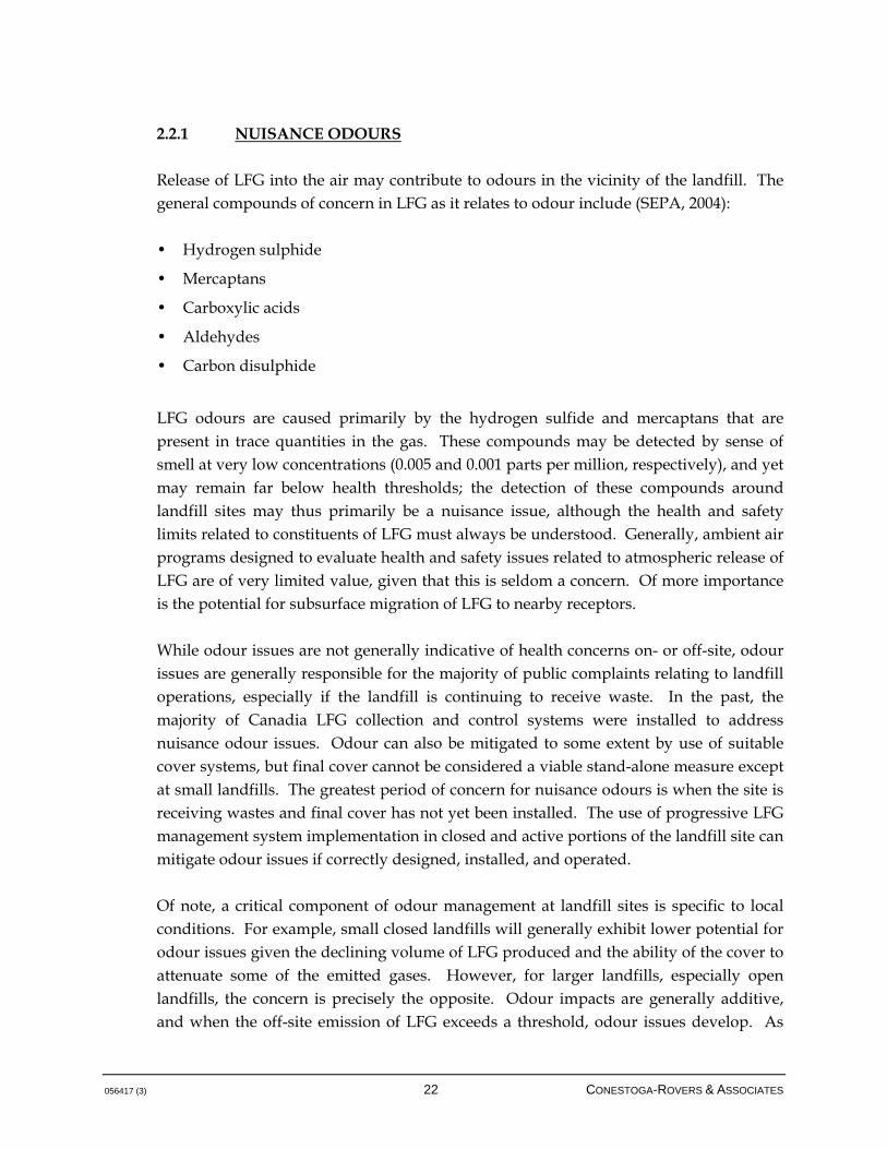
2.2.1 NUISANCE ODOURS
Release of LFG into the air may contribute to odours in the vicinity of the landfill. The general compounds of concern in LFG as it relates to odour include (SEPA, 2004): • Hydrogen sulphide
• Mercaptans
• Carboxylic acids
• Aldehydes
• Carbon disulphide
LFG odours are caused primarily by the hydrogen sulfide and mercaptans that are present in trace quantities in the gas. These compounds may be detected by sense of smell at very low concentrations (0.005 and 0.001 parts per million, respectively), and yet may remain far below health thresholds; the detection of these compounds around landfill sites may thus primarily be a nuisance issue, although the health and safety limits related to constituents of LFG must always be understood. Generally, ambient air programs designed to evaluate health and safety issues related to atmospheric release of LFG are of very limited value, given that this is seldom a concern. Of more importance is the potential for subsurface migration of LFG to nearby receptors. While odour issues are not generally indicative of health concerns on- or off-site, odour issues are generally responsible for the majority of public complaints relating to landfill operations, especially if the landfill is continuing to receive waste. In the past, the majority of Canadia LFG collection and control systems were installed to address nuisance odour issues. Odour can also be mitigated to some extent by use of suitable cover systems, but final cover cannot be considered a viable stand-alone measure except at small landfills. The greatest period of concern for nuisance odours is when the site is receiving wastes and final cover has not yet been installed. The use of progressive LFG management system implementation in closed and active portions of the landfill site can mitigate odour issues if correctly designed, installed, and operated. Of note, a critical component of odour management at landfill sites is specific to local conditions. For example, small closed landfills will generally exhibit lower potential for odour issues given the declining volume of LFG produced and the ability of the cover to attenuate some of the emitted gases. However, for larger landfills, especially open landfills, the concern is precisely the opposite. Odour impacts are generally additive, and when the off-site emission of LFG exceeds a threshold, odour issues develop. As

056417 (3) 23 CONESTOGA-ROVERS & ASSOCIATES
the landfill continues to expand and generate LFG, additional volumes of LFG will need to be managed to maintain emissions below the threshold for odour impacts. This infers that the collection efficiency of LFG management systems must continually increase to prevent nuisance issues; a static objective and efficiency for a LFG management system at a large open landfill is thus likely not appropriate. This concern is particularly relevant to the BC context, where there are active landfills of relatively small size but also sites that will be classified as very large in the context of Canadian landfills. 2.2.2 RELEASE OF GREENHOUSE GASES TO THE ATMOSPHERE
As previously mentioned, the methane component of LFG is considered to be a net contributor to GHG emissions. Global warming is thought to be caused by increases in atmospheric concentrations of GHGs, such as CO2, CH4, chlorofluorocarbons (CFCs), nitrous oxide (N2O), water vapour, and non-methane organic compounds (NMOCs). These gases are normally present in the atmosphere and serve as a "thermal blanket" for the Earth. GHGs allow solar radiation to pass through the atmosphere while absorbing a portion of the infrared radiation that is emitted back from the Earth's surface (see Figure 2.4). The absorption of radiation warms the atmosphere to regulate the climate. The earth would be about 30 degrees Celsius colder without the presence of the GHGs (Government of Canada, Canada's National Report on Climate Change, 1994). Worldwide methane generated from the landfilling of municipal solid waste represented over 12 percent of total global methane emissions in 2000. Global methane emissions from landfills are expected to grow by 9 percent between 2005 and 2020. Most developed countries have regulations that will constrain and potentially reduce future growth in methane emissions from landfills. However, areas of the world such as Eastern Europe and China are projected to experience steady growth in landfill methane collection because of improved waste management practices diverting more MSW into managed landfills (US EPA, 2006). As mentioned in Section 2.0, methane is a more harmful GHG than CO2 because of its effect on other atmospheric molecules. The carbon dioxide component of LFG is generally considered to be biogenic (i.e., it will be emitted in any case by the degradation of waste materials); the general assumption is that the methane is an additional emission that is created by the very nature of landfilling practice. Similarly, carbon dioxide from the combustion of LFG is generally considered to be part of the natural carbon cycle and is thus not considered a net contributor to GHG emissions.

056417 (3) 25 CONESTOGA-ROVERS & ASSOCIATES
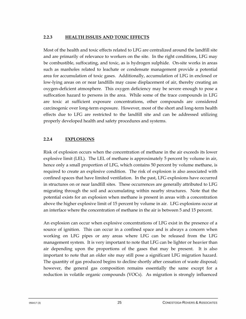
2.2.3 HEALTH ISSUES AND TOXIC EFFECTS
Most of the health and toxic effects related to LFG are centralized around the landfill site and are primarily of relevance to workers on the site. In the right conditions, LFG may be combustible, suffocating, and toxic, as is hydrogen sulphide. On-site works in areas such as manholes related to leachate or condensate management provide a potential area for accumulation of toxic gases. Additionally, accumulation of LFG in enclosed or low-lying areas on or near landfills may cause displacement of air, thereby creating an oxygen-deficient atmosphere. This oxygen deficiency may be severe enough to pose a suffocation hazard to persons in the area. While some of the trace compounds in LFG are toxic at sufficient exposure concentrations, other compounds are considered carcinogenic over long-term exposure. However, most of the short and long-term health effects due to LFG are restricted to the landfill site and can be addressed utilizing properly developed health and safety procedures and systems. 2.2.4 EXPLOSIONS
Risk of explosion occurs when the concentration of methane in the air exceeds its lower explosive limit (LEL). The LEL of methane is approximately 5 percent by volume in air, hence only a small proportion of LFG, which contains 50 percent by volume methane, is required to create an explosive condition. The risk of explosion is also associated with confined spaces that have limited ventilation. In the past, LFG explosions have occurred in structures on or near landfill sites. These occurrences are generally attributed to LFG migrating through the soil and accumulating within nearby structures. Note that the potential exists for an explosion when methane is present in areas with a concentration above the higher explosive limit of 15 percent by volume in air. LFG explosions occur at an interface where the concentration of methane in the air is between 5 and 15 percent. An explosion can occur when explosive concentrations of LFG exist in the presence of a source of ignition. This can occur in a confined space and is always a concern when working on LFG pipes or any areas where LFG can be released from the LFG management system. It is very important to note that LFG can be lighter or heavier than air depending upon the proportions of the gases that may be present. It is also important to note that an older site may still pose a significant LFG migration hazard. The quantity of gas produced begins to decline shortly after cessation of waste disposal; however, the general gas composition remains essentially the same except for a reduction in volatile organic compounds (VOCs). As migration is strongly influenced

056417 (3) 26 CONESTOGA-ROVERS & ASSOCIATES
by the physical setting of the site, hazards may still be present well into the declining phases of gas generation. As mentioned above, explosions have been reported in buildings adjacent to landfill properties, and thus LFG management systems must be able to control off-site migration. Management systems have been developed to reduce the driving force for LFG migration (on-site in-waste gas extraction control), intercept migrating gas (active or passive ventilation systems), and provide additional ventilation and protection systems for off-site building (subsurface collection systems or enhanced in-building ventilation systems and gas detection). Explosion hazards resulting from LFG migrating through subsurface soils are one of the most important health-related effects attributed to LFG, and thus control systems should be designed with this concern in mind. 2.2.5 VEGETATION STRESS
Vegetation stress is a sign of LFG migration through the subsurface or through the final landfill cover and occurs because plant roots are deprived of oxygen; it is also possible that LFG carries components that are directly toxic to plants (SEPA, 2004). Deterioration of vegetation on and near landfills may be both an aesthetic and a practical problem. In areas where vegetative cover is diminished, erosion of the cover may occur. This may lead to a "cascade" effect resulting in increased LFG emissions. Vegetation stress alone is generally not a sufficient cause to implement LFG controls. It is, however, an indication of significant LFG migration in the subsurface, which may lead to other more serious issues. Vegetation stress on the final landfill cover is also an indication of an area that may require additional cover material in order to increase the efficiency of a LFG management system. Potential LFG impact to vegetation is also a concern when selecting cover vegetation and final landscaping of the closed landfill. Vegetative stress may also indicate the need for additional LFG control by the installation of vertical extraction wells in the area. 2.3 LANDFILL GAS QUANTITY
LFG is generated as a result of physical, chemical, and microbial processes occurring within the waste. Due to the organic nature of most waste, the microbial processes
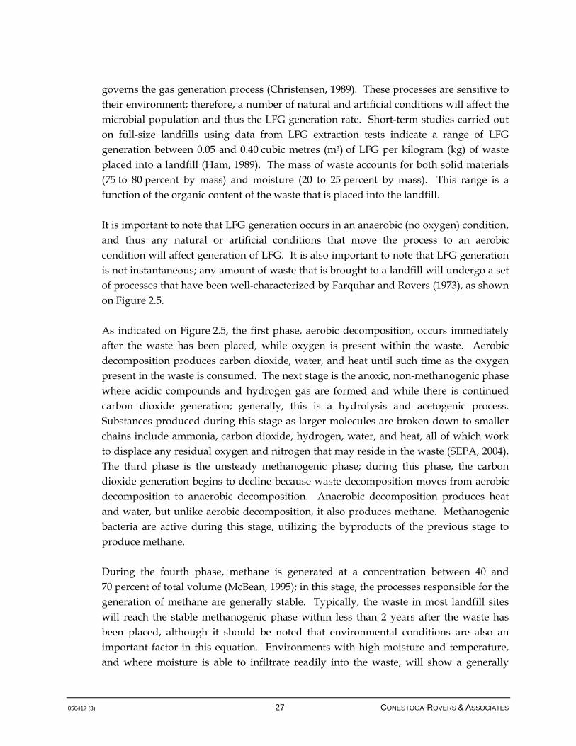
056417 (3) 27 CONESTOGA-ROVERS & ASSOCIATES
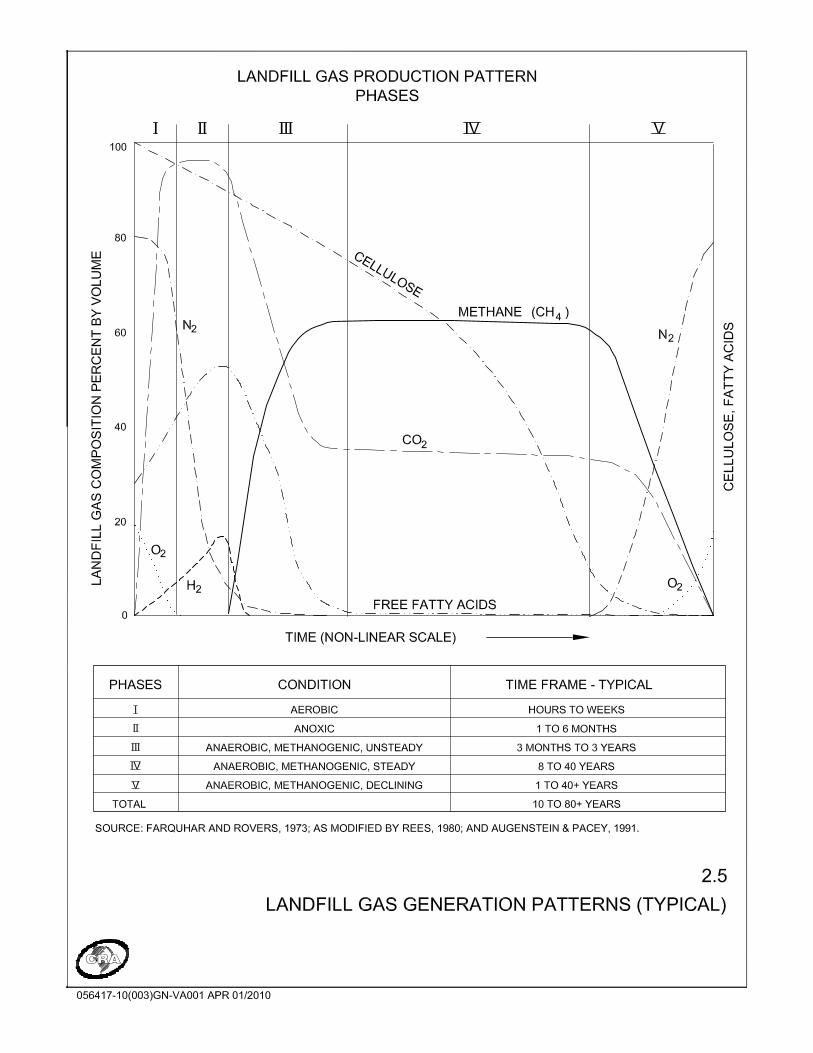
governs the gas generation process (Christensen, 1989). These processes are sensitive to their environment; therefore, a number of natural and artificial conditions will affect the microbial population and thus the LFG generation rate. Short-term studies carried out on full-size landfills using data from LFG extraction tests indicate a range of LFG generation between 0.05 and 0.40 cubic metres (m3) of LFG per kilogram (kg) of waste placed into a landfill (Ham, 1989). The mass of waste accounts for both solid materials (75 to 80 percent by mass) and moisture (20 to 25 percent by mass). This range is a function of the organic content of the waste that is placed into the landfill. It is important to note that LFG generation occurs in an anaerobic (no oxygen) condition, and thus any natural or artificial conditions that move the process to an aerobic condition will affect generation of LFG. It is also important to note that LFG generation is not instantaneous; any amount of waste that is brought to a landfill will undergo a set of processes that have been well-characterized by Farquhar and Rovers (1973), as shown on Figure 2.5. As indicated on Figure 2.5, the first phase, aerobic decomposition, occurs immediately after the waste has been placed, while oxygen is present within the waste. Aerobic decomposition produces carbon dioxide, water, and heat until such time as the oxygen present in the waste is consumed. The next stage is the anoxic, non-methanogenic phase where acidic compounds and hydrogen gas are formed and while there is continued carbon dioxide generation; generally, this is a hydrolysis and acetogenic process. Substances produced during this stage as larger molecules are broken down to smaller chains include ammonia, carbon dioxide, hydrogen, water, and heat, all of which work to displace any residual oxygen and nitrogen that may reside in the waste (SEPA, 2004). The third phase is the unsteady methanogenic phase; during this phase, the carbon dioxide generation begins to decline because waste decomposition moves from aerobic decomposition to anaerobic decomposition. Anaerobic decomposition produces heat and water, but unlike aerobic decomposition, it also produces methane. Methanogenic bacteria are active during this stage, utilizing the byproducts of the previous stage to produce methane. During the fourth phase, methane is generated at a concentration between 40 and 70 percent of total volume (McBean, 1995); in this stage, the processes responsible for the generation of methane are generally stable. Typically, the waste in most landfill sites will reach the stable methanogenic phase within less than 2 years after the waste has been placed, although it should be noted that environmental conditions are also an important factor in this equation. Environments with high moisture and temperature, and where moisture is able to infiltrate readily into the waste, will show a generally
056417 (3) 28 CONESTOGA-ROVERS & ASSOCIATES
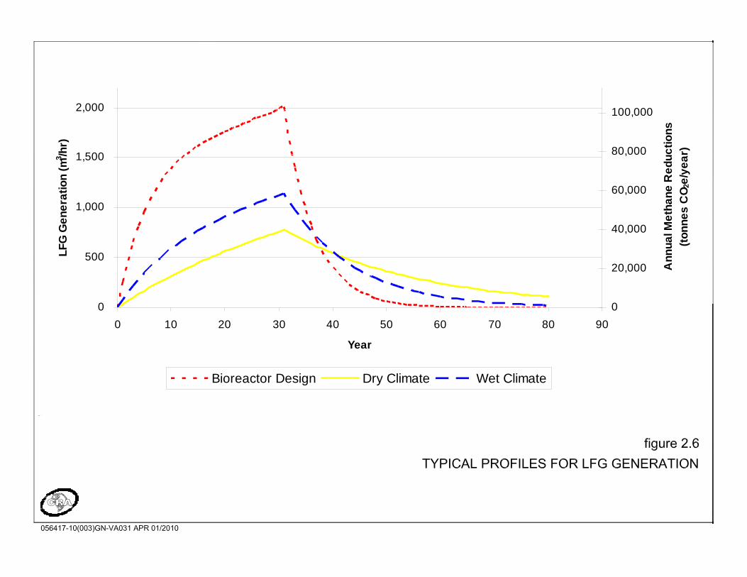
shorter timeframe for reaching the stable methanogenic phase. In extreme conditions, the timeframe for reaching this stage can be on the order of months. Given the varied climate patterns and landfill conditions in BC, the lag time for reaching steady anaerobic conditions may vary. LFG may be produced at a site for a number of decades dependent on landfill conditions and type and age of waste, with emissions continuing at declining levels from the date of placement. This can be seen in Figure 2.6, which shows a typical profile for LFG generation at a site. Note, as expected, that LFG generation begins to decline after the landfill is closed, as closure ends the replenishment of organic material. A number of factors control the amount and rate of LFG generation, as discussed in Section 2.3.1.

056417 (3) 30 CONESTOGA-ROVERS & ASSOCIATES
2.3.1 WASTE COMPOSITION
Waste composition is the most important factor in assessing the LFG generation potential and total yield at a site. The maximum potential volume of LFG is dependent on the quantity and type of organic content within the waste mass (Environment Canada, 1996), since the decomposing organic wastes are the major source for all LFG produced. The link between waste composition and LFG generation is clear. Inorganic and inert wastes will produce little or no LFG; more organic wastes will produce greater amounts of LFG on a per unit mass basis, but it is important to keep in mind that it is the actual organic fraction of the waste that produces LFG. Highly-organic wastes such as food wastes are able to produce LFG, but also comprise largely water, which inherently does not produce LFG but will aid the rate of LFG evolution. The same consideration is true of the rate of generation. The same waste mix and mass placed in an arid environment versus a humid environment contains the same overall potential for generating LFG; however, the relative rate of this generation will occur at a more ready pace in the more humid environment if moisture is allowed to infiltrate into the landfill. Excess amounts of moisture, however, will not continue to support this effect. Currently, there is a trend in Canada towards organics diversion from landfills. This generally revolves around the implementation of source-separated organics (SSO) systems that require the public to collect organics and direct these materials to a separate collection stream. Often, these organics (largely food and yard wastes) are composted, although there is a small fraction of SSO that is anaerobically digested for energy generation. As SSO programs become mature across the country, it can be expected that the profile of wastes directed to landfill will change; in BC, a number of BC jurisdictions are already undertaking an SSO program. The removal of food wastes will certainly change the overall profile of LFG generation, although the overall effects of this removal are not fully understood at this point. As discussed above, it is the shape of the gas generation curve that may be most significantly-altered, rather than the total potential gas generation. This point is of particular concern when designing LFG management systems, and in particular, when assessing the viability of LFG utilization. 2.3.2 MOISTURE CONTENT
The amount of moisture within a landfill is considered to be one of the most important parameters controlling gas generation rates; to some extent, the amount of moisture may

056417 (3) 31 CONESTOGA-ROVERS & ASSOCIATES
affect the ultimate methane generation potential of the waste, but the primary effect is related to the rate of generation. See Figure 2.6 for typical gas profiles for both a "dry" and a "wet" landfill with the same waste composition and deposition rate; in the latter case, the gas generation profile is more peaked and drops off to lower levels at a faster rate. Understanding the relevant moisture conditions and water balance of a landfill is important in predicting the amount of LFG generation and thus is a part of the design basis for LFG collection systems. Given the wide variety of climate in BC (ranging from average annual precipitation rates of under 250 mm/year [10 inches/year] to over 3,000 mm/year [120 inches/year]), LFG generation profiles may be quite different and the response in terms of control must suit the local conditions. Note as well that waste has its own inherent moisture when it reaches a landfill, so the moisture content consideration is not solely related to environmental conditions. Generally, for municipal solid wastes that include food wastes, etc., sufficient moisture is available in the waste to initiate the methanogenic cycle. Moisture provides the aqueous environment necessary for gas generation and also serves as a medium for transporting nutrients and bacteria. The moisture content in the landfill is strongly influenced by climatic conditions (temperature, rainfall, etc.), initial moisture content of the waste, and specific landfill design such as type of base liner, type of leachate collection system, type of cover, and programs such as bioreactor/rapid stabilization with or without leachate recycling. Landfills are typically constructed and filled in a sequential layered pattern. This factor is important in understanding how moisture moves into and through the waste. The layering effect tends to result in substantially different flow characteristics for the movement of leachate and infiltration of water into the landfill, and may have an effect on LFG movement within the waste. It is possible to somewhat control the rate of LFG generation through engineered waste management systems. Conventional sanitary landfills as practiced in North America in the 1970s and 80s are generally referred to as "dry tombs" because the approach taken in designing them was to minimize water contacting the waste with a view toward minimizing the potential for the resulting leachate to enter the groundwater. However, this practice also limits the rate of anaerobic activity within the waste and potentially increases the contaminating lifespan of the waste.
0
500
1,000
1,500
2,000
0 10 20 30 40 50 60 70 80 90
Year
LF
G G
en
era
tio
n (
m3 /h
r)
0
20,000
40,000
60,000
80,000
100,000
An
nu
al M
eth
an
e R
ed
uc
tio
ns
(to
nn
es
CO
2e/y
ea
r)
Bioreactor Design Dry Climate Wet Climate
056417 (3) 33 CONESTOGA-ROVERS & ASSOCIATES
The current trend is towards landfill bioreactor technology systems, which augment the amount of water contacting the waste to rapidly stabilize the wastes. This technique can produce large initial LFG generation rates while decreasing their rate of generation sharply after the cessation of waste acceptance. However, it is important to note that rapid stabilization of a landfill can result in effects on other landfill systems, including leachate collection and existing LFG collection systems because of the increased rate of waste decomposition and settling, and the addition of liquids that may be intercepted by horizontal collection pipes or bedding material. These programs should be undertaken with great care when the technology is retrofitted into existing landfills, and is likely more appropriate for purpose-built landfills or landfill cells that have been constructed to take the various factors into account. Figure 2.6 additionally shows the gas profile for a bioreactor landfill, for illustrative purposes; in some situations, LFG generation rates have been increased by more than an order of magnitude as a result of bioreactor technology (McBean, 2005). 2.3.3 TEMPERATURE
The temperature within a landfill tends to be higher than ambient air temperatures since the anaerobic decomposition that occurs is an exothermic process (i.e., gives off heat). Temperature conditions within a landfill influence the type of bacteria that are predominant and the rate of gas generation. The rates of decomposition and gas generation decrease with decreasing temperature. Landfill temperature is influenced by the depth of the landfill. Where the landfill is deep, temperatures tend to equilibrate. Where a landfill is shallow, temperatures are often more influenced by surface effects and weather conditions. Generally, it is expected that landfill temperatures are on the order of 30 to 40 degrees Celsius during the stable final phase of methanogenesis. Such conditions are likely to be achieved even in colder climates, as the landfill temperature is most strongly a function of biological activity than it is of ambient conditions. Of note, LFG may demonstrate higher or lower temperatures than typical at centralized collection points (such as at flares) if the run of gas is undertaken through piping that will be influenced by subsurface temperatures or by ambient conditions if the collection piping is above grade.
056417 (3) 34 CONESTOGA-ROVERS & ASSOCIATES
2.3.4 pH AND NUTRIENTS
The pH of the waste and leachate significantly influences the rate of gas generation. The generation of methane in landfills is greatest when neutral pH conditions exist. Where acidic conditions develop as a result of rapid buildup of broken down products, some delay in methane generation may occur (SEPA, 2004), but a landfill generally has sufficient buffering capacity to mitigate this effect. Bacteria in a landfill require various nutrients for growth, primarily carbon, hydrogen, nitrogen, and phosphorus. In general, municipal solid waste contains the nutrients necessary to support the decomposition process that generates methane gas. Numerous toxic materials, such as heavy metals, can retard bacterial growth in portions of a site and consequently slow gas generation. While attempts have been made to supplement the landfill environment with nutrients and bacteria, the results of these studies have not, at this point, generated sufficiently strong evidence to support this technique. 2.3.5 WASTE DENSITY AND PARTICLE SIZE
The particle size and density of the waste influence LFG generation rates by affecting the transport of nutrients and moisture throughout the landfill. Also, the smaller particle sizes of shredded waste are believed to increase the rate of LFG generation. A difference in waste density exists as a result of compaction practices at landfills, but it should also be noted that landfill waste will compact further over time, especially if waste depths are deep, as a result of the above-lying waste weight. This is of particular significance for LFG management, where collection may be inhibited in the lower portions of the landfill if the waste is highly consolidated. This factor should be evaluated against, for example, the ultimate depth of vertical gas extraction wells. 2.3.6 LFG GENERATION MODELLING
LFG models are the most common method used to estimate LFG generation from a landfill site over time. These models are typically used to: • Size LFG collection, combustion, and utilization systems
• Estimate GHG emissions and potential emissions reductions
• Evaluate the regulatory context for sites

056417 (3) 35 CONESTOGA-ROVERS & ASSOCIATES
The cost of modelling LFG generation is relatively low. Generally available features and data for a specific landfill need to be defined to predict a range of LFG generation with time. Several models have been developed by various researchers and companies. Most models predict LFG generation over time from landfilled wastes. The yearly tonnage is typically used as a unit batch, and therefore the models predict LFG generation for a specific mass of waste landfilled in a given year. Total LFG generation from a landfill is simply the sum of yearly outputs computed over time by applying the model to the yearly tonnage of waste. Typically, these models include a time interval before generation starts (lag time) and, depending on the model, intervals of rising, constant, and falling generation. Any model output is only as good as the input data and often very broad assumptions are necessary for estimating waste quantities and types. Therefore, it is appropriate to use a simple model, which employs fewer parameters that can be more reasonably assigned according to specific site conditions. The predictive success of any model is dependent mostly on the degree of accuracy needed, the reliability of the input data, and the experience of the individual analyzing the data. All models used for determining the estimated LFG generation rate of the site should be subject to a thorough sensitivity analysis to determine a range of potential outcomes, and analyze which parameters have the greatest influence on the results. Identification of sensitive parameters can lead to directed data collection and future improvement in LFG generation predictions. Given the heterogeneous nature of the conditions within the landfill and the typical limitations of the input data that is most often available for a candidate site, it is recommended that a range of values be established for the sensitivity analysis. Using the upper and lower bounds of a LFG generation versus time profile based on the likely conditions within the landfill, it is possible to assign values and design inputs that are suitable for use in assessing the LFG generation potential for a site and any risk factors that may be applicable. LFG generation modelling is the main initial input for determining the design of the LFG management system and must be undertaken with appropriate input parameters and using experience in the field. First-order kinetic models are frequently used to estimate the generation of methane
over the life of a landfill. These models are tailored to specific landfills by a number of assumptions about conditions at the site. The empirical, first-order decay model most widely accepted and used by industry and regulatory agencies, including the United States Environmental Protection Agency (USEPA), is the relatively simple and
056417 (3) 36 CONESTOGA-ROVERS & ASSOCIATES
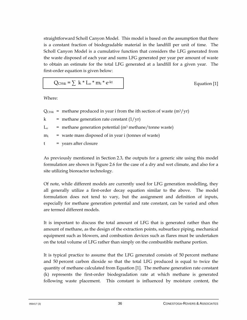
straightforward Scholl Canyon Model. This model is based on the assumption that there is a constant fraction of biodegradable material in the landfill per unit of time. The Scholl Canyon Model is a cumulative function that considers the LFG generated from the waste disposed of each year and sums LFG generated per year per amount of waste to obtain an estimate for the total LFG generated at a landfill for a given year. The first-order equation is given below:
Equation [1]
Where: QCH4i = methane produced in year i from the ith section of waste (m3/yr)
k = methane generation rate constant (1/yr)
Lo = methane generation potential (m3 methane/tonne waste)
mi = waste mass disposed of in year i (tonnes of waste)
t = years after closure
As previously mentioned in Section 2.3, the outputs for a generic site using this model formulation are shown in Figure 2.6 for the case of a dry and wet climate, and also for a site utilizing bioreactor technology. Of note, while different models are currently used for LFG generation modelling, they all generally utilize a first-order decay equation similar to the above. The model formulation does not tend to vary, but the assignment and definition of inputs, especially for methane generation potential and rate constant, can be varied and often are termed different models. It is important to discuss the total amount of LFG that is generated rather than the amount of methane, as the design of the extraction points, subsurface piping, mechanical equipment such as blowers, and combustion devices such as flares must be undertaken on the total volume of LFG rather than simply on the combustible methane portion. It is typical practice to assume that the LFG generated consists of 50 percent methane and 50 percent carbon dioxide so that the total LFG produced is equal to twice the quantity of methane calculated from Equation [1]. The methane generation rate constant (k) represents the first-order biodegradation rate at which methane is generated following waste placement. This constant is influenced by moisture content, the
QCH4i = ∑ k * Lo * mi * e-kt
056417 (3) 37 CONESTOGA-ROVERS & ASSOCIATES
availability of nutrients, pH, and temperature. As mentioned previously, the moisture content within a landfill is one of the most important parameters affecting the gas generation rate. The methane generation potential speaks to the amount of methane that can be generated by a given quantity of waste, and is most strongly a function of the waste composition. As previously noted, it is important to understand the relative effects of future waste volumes and how waste composition may alter as a function of, for example, SSO collection systems. The following design standard (as stated in the Regulation) must be adhered to prior to the design of a LFG management system. Design Standard 1
Note that the BC MOE has issued a LFG Generation Assessment Procedure Guidance Report and a LFG Generation Estimation Tool (British Columbia, Landfill Gas Management Regulation, available at http://www.env.gov.bc.ca/epd/codes/landfill_gas/index.htm), for the purposes of assessing landfill sites against the regulatory 1,000 tonnes of methane generated per year threshold. The basis of this tool is also a first-order kinetic model, but a range of methane generation potentials and rate coefficients have been assigned to describe both the waste composition and environmental conditions such as precipitation, but also the combined effect of these parameters. For example, it is clear that a highly biodegradable waste in a very humid environment is likely to generate high quantities of LFG and at a significant rate; however, it will not be reasonable to assume that an inert waste in a wet environment will produce significant LFG. The assessment tool describes these relative effects in the context of the BC climate, which varies highly from area to area. As per the LFG Generation Estimation Tool, annual quantities of waste accepted at a regulated landfill are to be segregated into three categories by mass: relatively inert, moderately decomposable, and decomposable. Estimated future filling rates are also required. Methane generation potentials (Lo) are provided for each category of waste. Methane generation rates (k) are provided for each category of waste, depending on the average precipitation at the landfill. Refer to the LFG Generation Assessment Procedure Guidance Report for more information regarding the LFG Generation Estimation Tool
The results of the LFG generation assessment conducted in accordance with the Regulation will provide the basic inputs to design the LFG management system.
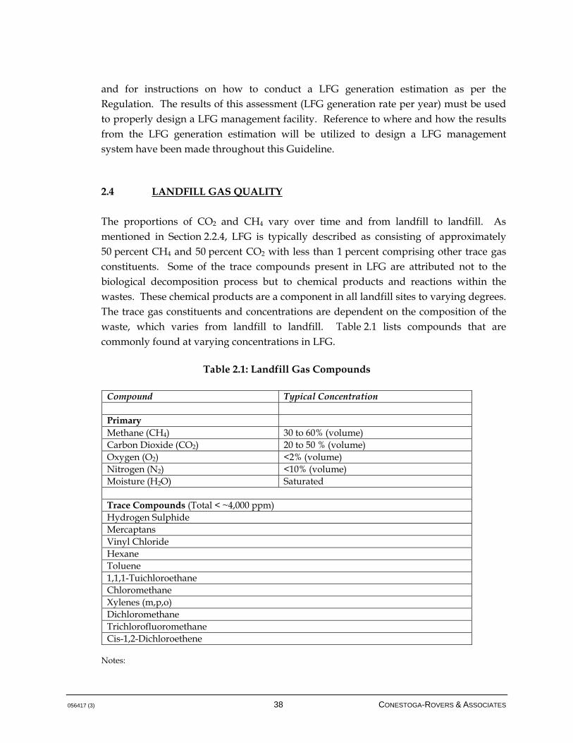
056417 (3) 38 CONESTOGA-ROVERS & ASSOCIATES
and for instructions on how to conduct a LFG generation estimation as per the Regulation. The results of this assessment (LFG generation rate per year) must be used to properly design a LFG management facility. Reference to where and how the results from the LFG generation estimation will be utilized to design a LFG management system have been made throughout this Guideline. 2.4 LANDFILL GAS QUALITY
The proportions of CO2 and CH4 vary over time and from landfill to landfill. As mentioned in Section 2.2.4, LFG is typically described as consisting of approximately 50 percent CH4 and 50 percent CO2 with less than 1 percent comprising other trace gas constituents. Some of the trace compounds present in LFG are attributed not to the biological decomposition process but to chemical products and reactions within the wastes. These chemical products are a component in all landfill sites to varying degrees. The trace gas constituents and concentrations are dependent on the composition of the waste, which varies from landfill to landfill. Table 2.1 lists compounds that are commonly found at varying concentrations in LFG.
Table 2.1: Landfill Gas Compounds
Compound Typical Concentration Primary Methane (CH4) 30 to 60% (volume) Carbon Dioxide (CO2) 20 to 50 % (volume) Oxygen (O2) <2% (volume) Nitrogen (N2) <10% (volume) Moisture (H2O) Saturated Trace Compounds (Total < ~4,000 ppm) Hydrogen Sulphide Mercaptans Vinyl Chloride Hexane Toluene 1,1,1-Tuichloroethane Chloromethane Xylenes (m,p,o) Dichloromethane Trichlorofluoromethane Cis-1,2-Dichloroethene
Notes:
056417 (3) 39 CONESTOGA-ROVERS & ASSOCIATES
This list represents trace constituents that are commonly found in LFG. Concentrations and compounds vary greatly from site to site.
Assumes LFG generation phase is at anaerobic, methanogenic steady stage. Low concentrations of oxygen and nitrogen may be present as a result of being entrained in the site or
may be drawn into the site by active gas extraction. Sources: CRA 1994; United States Environmental Protection Agency (USEPA) 1993; and Environment Canada 1995.
Generally, the composition of the main LFG gases remains constant during the generation phase, and it is the volume of LFG that declines over time. Although the composition of the dominant compounds, methane and carbon dioxide, is generally uniform during the generation phase, differences in composition are observed at times, especially at landfill sites with active gas collection systems. In these cases, the collected LFG may demonstrate lower amounts of methane and carbon dioxide and potentially higher amounts of oxygen and nitrogen, but this is attributed to the operation of the LFG management system and potential intrusion of atmospheric air into the landfill environment than to the composition of LFG when it is generated. Additionally, the composition of migrating LFG may be altered in terms of the methane/carbon dioxide ratio, especially at older sites and where the migration pathway to off-site monitoring points is large. As LFG migrates, the carbon dioxide component dissolves into soil water far more readily than does methane, which has very limited solubility in water, thus creating a migrating LFG volume that may show higher-than-normal composition of methane as compared to carbon dioxide. As LFG volumes decline and the absorptive capacity of soil water increases relative to the LFG flow, this effect becomes more important, and the composition difference more pronounced. LFG has a number of other important characteristics. One of the most important is that LFG is saturated with moisture or water vapour. The presence of saturation levels of water in LFG is a particular design parameter of importance, as when LFG is transmitted towards the combustion and/or utilization system, the gas temperature can change and liberate water vapour into a liquid form (condensate). The water holding capacity of LFG is also a function of temperature; a general guide for the saturation water content of LFG at ambient pressures is presented in Table 2.2.

056417 (3) 40 CONESTOGA-ROVERS & ASSOCIATES
Table 2.2: Saturation Water Content of LFG at Ambient Pressure
LFG Temperature (ºC)
Saturation Density (L/m3)
0 5 20 17 40 51
Even if condensate is removed from a LFG stream, there may be an additional need to remove moisture prior to the utilization of gas. LFG will also contain some amount of particulate matter, generally drawn from the waste with advecting gas, and potentially increased when a gas collection system is active. Given the moisture present in the gas and the potential for condensation of this vapour, some amount of particulate is deposited during the transmission of LFG through the piping system. Generally, particulate matter is not a concern for flaring applications, but it may require removal prior to utilization depending on the specific requirements. Sulphur compounds are trace compounds found in all types of biogas. Their concentration and composition vary with the feedstock from which they were generated. Sulphur compounds found in biogas include sulphides, thiols, and mercaptans, many of which are highly odorous. Of all sulphur compounds that may be present in biogas, hydrogen sulphide is generally the most important contaminant as it relates to odour, health and safety, and potentially utilization system operations. Although combustion typically destroys 99 percent of hydrogen sulphide with emissions likely to be below most local risk thresholds (SEPA, 2004), hydrogen sulphide can adversely affect downstream biogas utilization equipment. Hydrogen sulphide is produced under anaerobic conditions by sulphate-reducing microorganisms. In landfills, the sulphur required to produce hydrogen sulphide may originate from unlined landfills in sulphur-rich geological materials or quarries, landfills that accept sulphur-rich sludge from wastewater treatment plants or that use sulphate-rich soils as cover material, and landfills that accept large quantities of gypsum or drywall, such as construction and demolition landfills. LFG typically contains less than 100 ppm of hydrogen sulphide; however, in rare situations, the concentration can reach several thousand ppm where sulphur loading is high (SEPA, 2004). Of note, changes in hydrogen sulphide composition can occur as a result of emergency situations. In the United States, large volumes of construction and demolition debris were landfilled after Hurricane Katrina, with, in some cases, elevations in hydrogen sulphide levels in LFG by two to three orders of magnitude.
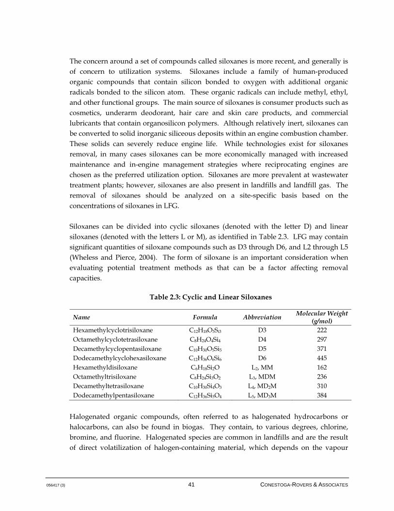
056417 (3) 41 CONESTOGA-ROVERS & ASSOCIATES
The concern around a set of compounds called siloxanes is more recent, and generally is of concern to utilization systems. Siloxanes include a family of human-produced organic compounds that contain silicon bonded to oxygen with additional organic radicals bonded to the silicon atom. These organic radicals can include methyl, ethyl, and other functional groups. The main source of siloxanes is consumer products such as cosmetics, underarm deodorant, hair care and skin care products, and commercial lubricants that contain organosilicon polymers. Although relatively inert, siloxanes can be converted to solid inorganic siliceous deposits within an engine combustion chamber. These solids can severely reduce engine life. While technologies exist for siloxanes removal, in many cases siloxanes can be more economically managed with increased maintenance and in-engine management strategies where reciprocating engines are chosen as the preferred utilization option. Siloxanes are more prevalent at wastewater treatment plants; however, siloxanes are also present in landfills and landfill gas. The removal of siloxanes should be analyzed on a site-specific basis based on the concentrations of siloxanes in LFG. Siloxanes can be divided into cyclic siloxanes (denoted with the letter D) and linear siloxanes (denoted with the letters L or M), as identified in Table 2.3. LFG may contain significant quantities of siloxane compounds such as D3 through D6, and L2 through L5 (Wheless and Pierce, 2004). The form of siloxane is an important consideration when evaluating potential treatment methods as that can be a factor affecting removal capacities.
Table 2.3: Cyclic and Linear Siloxanes
Name Formula Abbreviation Molecular Weight (g/mol)
Hexamethylcyclotrisiloxane C12H18O3Si3 D3 222 Octamethylcyclotetrasiloxane C8H24O4Si4 D4 297 Decamethylcyclopentasiloxane C10H30O5Si5 D5 371 Dodecamethylcyclohexasiloxane C12H36O6Si6 D6 445 Hexamethyldisiloxane C6H18Si2O L2, MM 162 Octamethyltrisiloxane C8H24Si3O2 L3, MDM 236 Decamethyltetrasiloxane C10H30Si4O3 L4, MD2M 310 Dodecamethylpentasiloxane C12H36Si5O4 L5, MD3M 384
Halogenated organic compounds, often referred to as halogenated hydrocarbons or halocarbons, can also be found in biogas. They contain, to various degrees, chlorine, bromine, and fluorine. Halogenated species are common in landfills and are the result of direct volatilization of halogen-containing material, which depends on the vapour

056417 (3) 42 CONESTOGA-ROVERS & ASSOCIATES
pressure of the species present in the landfill (SEPA, 2004); for example, contaminants with a higher vapour pressure will be stripped from the waste more quickly. The most common fluorinated species in landfills are chlorofluorocarbons (CFCs), which were used in refrigeration and propellants. CFCs use has been greatly reduced since the recognition that CFCs were primarily responsible for ozone depletion. Despite the reduction in CFC usage, CFCs persist at low levels due to slow volatilization from older waste. Other volatile organic compounds (VOCs) are present in landfills and also in LFG. The presence of VOCs in LFG is a physical process, and the general profile of VOC emission in LFG tends to decline at a much faster rate than does methane generation given that their removal is related to a stripping effect due to advecting LFG rather than due to a biological process. Table 2.4 presents other relevant parameters of LFG.
Table 2.4: Typical Parameters of LFG
LFG Parameter Value Density
Methane1 0.72 kg/m3 Carbon Dioxide1 1.98 kg/m3 LFG 1,2 1.35 kg/m3
Solubility Methane 35 mg/L at 17oC Carbon Dioxide 1.45 g/L at 25°C
Energy Content3 Methane 38 MJ/m3 LFG 2 19 MJ/m3
NOTES: 1 - Assumes LFG is at standard temperature and pressure (0 degrees Celsius and 1 atmosphere) 2 - Assume a 50-50 CH4/CO2 mixture 3 - Gross heating values presented All values are approximate and subject to change according gas composition, temperature and pressure Source: SEPA, 2004

056417 (3) 43 CONESTOGA-ROVERS & ASSOCIATES
3.0 LFG COLLECTION EFFICIENCY
The intent of this section is to discuss the goals and objectives of the BC MOE in releasing this document, which revolve around the development of quality LFG management systems that optimize GHG recovery. 3.1 COLLECTION EFFICIENCY STANDARDS AND OBJECTIVES
In the context of this document, collection efficiency will be defined as the average amount of LFG collected (in cubic metres per hour [m3/hr]) in the calendar year under consideration divided by the modelled amount of LFG generation at the site for the same calendar year, with all LFG flows normalized to 50 percent methane within the LFG composition. LFG collection efficiency can be estimated using the LFG Generation Estimation Tool for Annual Reporting which is available at http://www.env.gov.bc.ca/epd/codes/landfill_gas/index.htm. The LFG Generation Estimation Tool for Annual Reporting differs from the LFG Generation Estimation Tool in the LFG Generation Assessment Procedure Guidance in that all tonnage data from 1980 to the calendar year prior to the assessment is used. The LFG Generation Assessment Procedure Guidance, which includes the LFG Generation Estimation Tool, specifies a maximum period of 30 years of historical tonnage from the calendar year prior to the assessment be used. This definition is intended to take into account the following: • Any LFG management system downtime due to field or mechanical issues that will
result in a decrease in the average LFG collected flow rate.
• Operation of the LFG management system such that the average methane composition is below 50 percent and will result in a decrease in the average flow rate of LFG that is being collected.
• Any delay in accessing the active areas of the landfill for LFG collection will result in a decrease in collected flow relative to LFG generation; however, the LFG generation estimate will contain a lag period of one year for LFG generation. It must be recognized that there are significant integration issues in phasing the LFG system construction in conjunction with the overall landfill development and filling sequence.
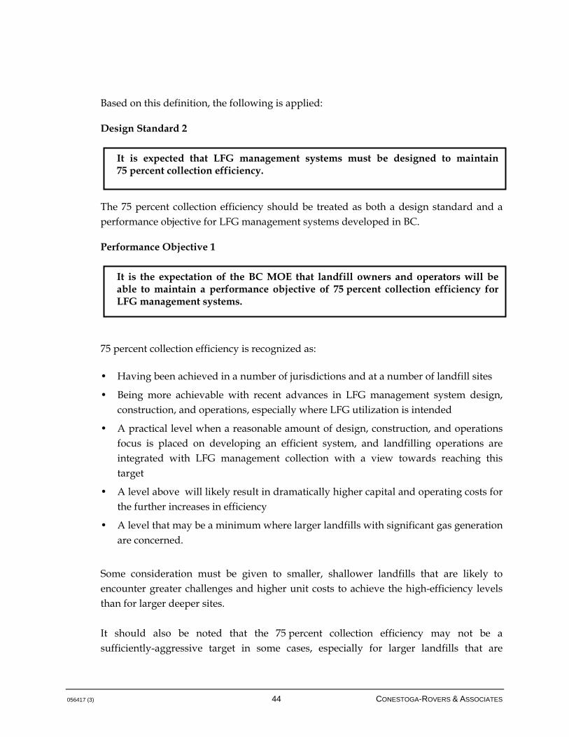
056417 (3) 44 CONESTOGA-ROVERS & ASSOCIATES
Based on this definition, the following is applied: Design Standard 2
The 75 percent collection efficiency should be treated as both a design standard and a performance objective for LFG management systems developed in BC. Performance Objective 1
75 percent collection efficiency is recognized as: • Having been achieved in a number of jurisdictions and at a number of landfill sites
• Being more achievable with recent advances in LFG management system design, construction, and operations, especially where LFG utilization is intended
• A practical level when a reasonable amount of design, construction, and operations focus is placed on developing an efficient system, and landfilling operations are integrated with LFG management collection with a view towards reaching this target
• A level above will likely result in dramatically higher capital and operating costs for the further increases in efficiency
• A level that may be a minimum where larger landfills with significant gas generation are concerned.
Some consideration must be given to smaller, shallower landfills that are likely to encounter greater challenges and higher unit costs to achieve the high-efficiency levels than for larger deeper sites. It should also be noted that the 75 percent collection efficiency may not be a sufficiently-aggressive target in some cases, especially for larger landfills that are
It is expected that LFG management systems must be designed to maintain 75 percent collection efficiency.
It is the expectation of the BC MOE that landfill owners and operators will be able to maintain a performance objective of 75 percent collection efficiency for LFG management systems.

056417 (3) 45 CONESTOGA-ROVERS & ASSOCIATES
characterized by higher volumes of LFG generated. In such cases, a higher collection efficiency may be needed to mitigate LFG release to the atmosphere, potentially causing localized odour issues. As a result, the 75 percent collection efficiency value should be used as a relative target, but should be assessed and rationalized by a qualified person on a site-specific basis to assign the actual and realistic performance standard for the specific site. This assessment must be included in the annual report submitted to the MOE for approval after LFG management system operations commence. In the case where a LFG management system exists at a site, this assessment shall be included in the LFG management facilities design plan for approval by the MOE and in the annual report. The following additional discussion is provided around the above performance objective in terms of potential challenges to meeting the target. This discussion is divided into two parts: LFG collection issues and LFG generation modelling. 3.1.1 LFG COLLECTION ISSUES
Existing LFG management systems may encounter challenges in reaching this level of collection efficiency if the infrastructure and systems were not initially designed and installed to meet this goal. It is recognized that landfill practices and conditions differ across BC. Generally, collection efficiencies can be higher where: • Landfill leachate is adequately controlled, through a combination of leachate
collection systems and effective surface water controls, such that mounding and surface water infiltration into the site do not impede effective collection of LFG
• Application of intermediate and final cover is staged in a manner to support efficient LFG collection from the waste while preventing intrusion of atmospheric air into the waste mass; daily and intermediate cover is staged and removed
• The waste is deep relative to the area of the landfill, requiring less physical infrastructure and improved opportunity for capturing LFG with lower risk of air intrusion and less sensitivity to well field monitoring and balancing
• Waste filling practices are consistent with the objective of collecting gas over the aerial extent of the landfill
• Operation of the LFG management system proceeds according to best management practices
056417 (3) 46 CONESTOGA-ROVERS & ASSOCIATES
It is noted that while the above items are under the control of the landfill owner/operator, site-specific conditions can diminish collection efficiency. It is expected that owner/operators will take these conditions into account when designing the LFG management system and adjust landfilling practices as required to meet the objective; further, the owner/operators will undertake operations of the LFG management system according to best management practices. It is also noted that the removal of daily and intermediate cover material is important to LFG management system operation, as non-removal creates barriers for perched leachate, limits interconnecting of waste lifts, and therefore impacts leachate collection and the operation of the LFG flare and/or utilization system. If the stated performance objective is not met, the owner/operators must provide detailed rationale to the BC MOE to explain why this is so and what will be done in an attempt to reach this objective the following year, in the required annual reports (see Section 11.1). 3.1.2 LFG GENERATION MODELLING ISSUES
A cautionary note should be made regarding LFG generation modelling. Inherently, LFG modelling can introduce variability through uncertainty in waste tonnages, but, more likely, inappropriate assignment of methane potential and rate constants. Another possible issue is the usage of models that incorporate differing or additional inputs that may be difficult to assign to landfills. While there are some more complex models available in the literature, these models generally require a level of detail in terms of input information that is not often available or cannot be reasonably estimated. For this reason, the definition of the collection efficiency can be skewed either upwards or downwards even if the LFG flow rate is correctly calculated, simply because the LFG generation estimate is incorrect. In order to mitigate this concern, some level of uniformity has been prescribed by the BC MOE to obtain consistent LFG generation estimates; namely, the amount of LFG generation must be estimated by using the BC MOE's LFG Generation Estimation Tool for Annual Reporting (British Columbia, Landfill Gas Management Regulation, which can be accessed from the BC MOE's website at the following link: http://www.env.gov.bc.ca/epd/codes/landfill_gas/index.htm). There must also be some consideration for any sites that have incorporated best management practices and yet are unable to achieve their theoretical efficiency target. The Guideline should be
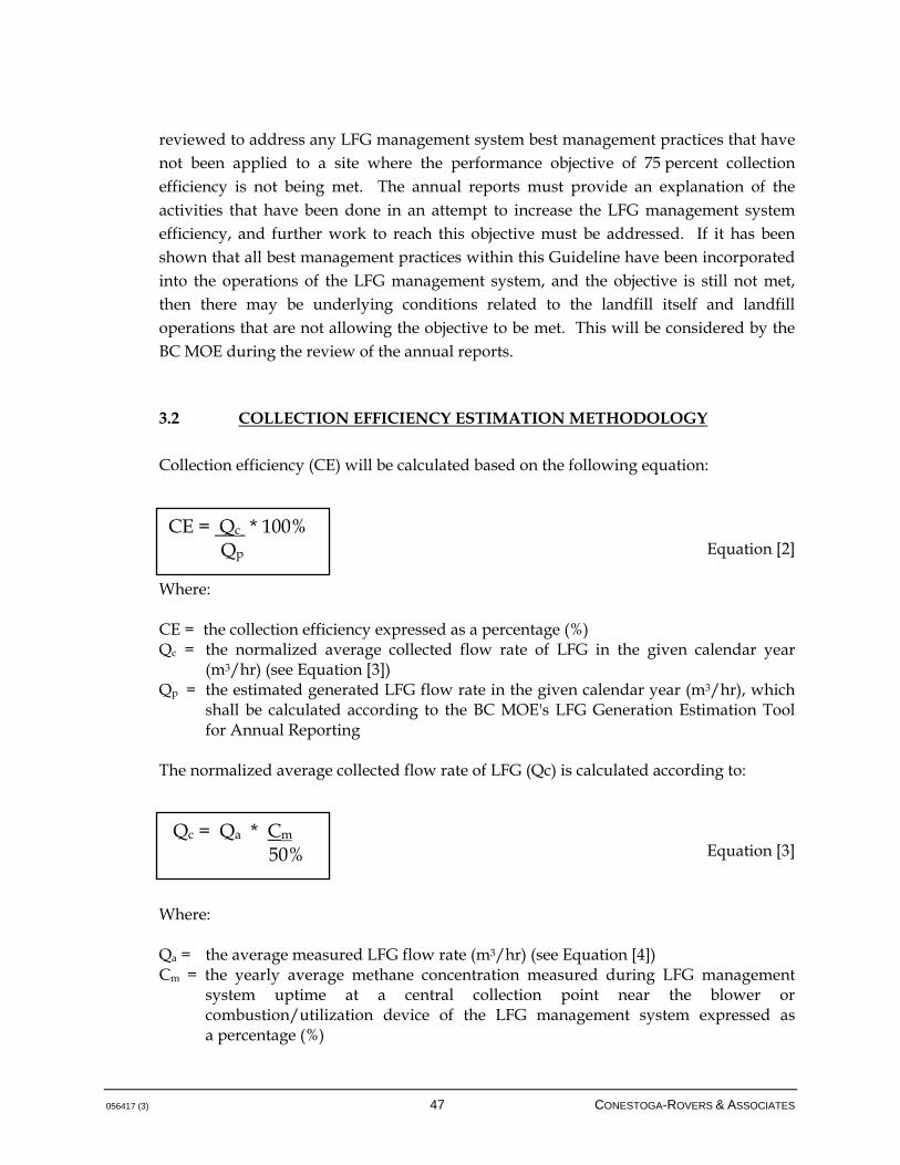
056417 (3) 47 CONESTOGA-ROVERS & ASSOCIATES
reviewed to address any LFG management system best management practices that have not been applied to a site where the performance objective of 75 percent collection efficiency is not being met. The annual reports must provide an explanation of the activities that have been done in an attempt to increase the LFG management system efficiency, and further work to reach this objective must be addressed. If it has been shown that all best management practices within this Guideline have been incorporated into the operations of the LFG management system, and the objective is still not met, then there may be underlying conditions related to the landfill itself and landfill operations that are not allowing the objective to be met. This will be considered by the BC MOE during the review of the annual reports. 3.2 COLLECTION EFFICIENCY ESTIMATION METHODOLOGY
Collection efficiency (CE) will be calculated based on the following equation:
Equation [2]
Where: CE = the collection efficiency expressed as a percentage (%) Qc = the normalized average collected flow rate of LFG in the given calendar year
(m3/hr) (see Equation [3]) Qp = the estimated generated LFG flow rate in the given calendar year (m3/hr), which
shall be calculated according to the BC MOE's LFG Generation Estimation Tool for Annual Reporting
The normalized average collected flow rate of LFG (Qc) is calculated according to:
Equation [3] Where: Qa = the average measured LFG flow rate (m3/hr) (see Equation [4]) Cm = the yearly average methane concentration measured during LFG management
system uptime at a central collection point near the blower or combustion/utilization device of the LFG management system expressed as a percentage (%)
CE = Qc * 100% Qp
Qc = Qa * Cm 50%

056417 (3) 48 CONESTOGA-ROVERS & ASSOCIATES
The average measured LFG flow rate (Qa) is measured according to the following:
Equation [4]
Where: VLFG = the total volume of LFG collected in the calendar year (m3/year) An example calculation utilizing the equations above is provided in Appendix B. The value of the collection efficiency, all assumptions inherent to the calculation, and the quantities specified above shall be communicated to the BC MOE via the required annual reports. Note that oxidation of LFG through the landfill cover will not be included in the calculation of LFG management system collection efficiency. While it is acknowledged that oxidation in cover soil does occur, this is not a primary LFG management strategy, is difficult to assess reliably, and shifts focus away from installation of LFG management systems that operate efficiently.
Qa = VLFG 24 * 365
056417 (3) 49 CONESTOGA-ROVERS & ASSOCIATES
4.0 OVERVIEW OF LANDFILL GAS MANAGEMENT FACILITIES DESIGN
Note that this document is generally intended for active landfills in BC that are subject to the BC LFG Management Regulation; however, the components of this Guideline may also be applied to smaller landfills or closed landfills that are not subject to the Regulation. The section below provides a general discussion of LFG management as it relates to design considerations and the potential requirement for passive barrier systems in addition to active LFG collection at regulated landfills. 4.1 DESIGN CONSIDERATIONS
The method for controlling LFG depends upon which of the potential impacts is identified as the primary control objective. For the purpose of selecting appropriate control technologies, the potential impacts of LFG may be grouped into those related to migration of LFG through soils surrounding the site, and those related to the release of LFG into the atmosphere (i.e., odour, air quality, atmospheric loading). A landfill site is a complex grouping of natural processes and integrated engineered systems, each of which is related to some degree to the others. The design of engineered control systems must take into consideration influencing factors created by and applied to other elements of the landfill system. The design of LFG controls must be integrated into the overall philosophy for design and operation of the site. The following subsections discuss design considerations that may affect potential LFG impacts and options for the control of LFG. 4.1.1 SITE CONFIGURATION
The configuration of the site may factor into the potential for LFG-related impacts. Sites that are filled predominantly above the surrounding grade may have an increased potential for release of LFG into the atmosphere due to the greater surface area of the landfill. Conversely, sites that are located predominantly below the surrounding grade have a greater potential for impacts related to migration of LFG into the surrounding soil.
056417 (3) 50 CONESTOGA-ROVERS & ASSOCIATES
A number of factors related to the angle of slopes on a landfill may affect the release of LFG to the atmosphere. Gentle landfill slopes (i.e., 4H:lV or less) may result in less gas being released to the atmosphere as a result of the following factors: • Ease of construction and maintenance of final cover, and therefore improved cover
integrity
• Increased ability to influence a larger portion of the waste mass with LFG collection wells or trenches, while reducing the potential for drawing air into the waste
The possible benefits of gentle slopes can be limited by the following considerations, depending on other landfill factors: • Very gentle slopes may result in ponding of water on the landfill. This will increase
infiltration into the site and thereby increase the site moisture content and LFG generation rates.
• Use of exclusively gentle side slopes is an inefficient use of landfill space.
4.1.2 COVER SYSTEM DESIGN
The primary factor pertaining to landfill cover that influences management of LFG is the permeability of the cover to moisture and gas. A permeable landfill cover such as coarse sand promotes infiltration of precipitation into the waste. As previously discussed, the moisture content of waste is a key parameter influencing the rate of LFG generation; it is also an important consideration in the ability to collect LFG, as high leachate levels will diminish the waste zone from which LFG can be captured. Within a fixed range, higher waste moisture content generally results in increased LFG generation over a shorter period. Permeable covers tend to allow for more rapid venting of LFG to the atmosphere. This may result in lower gas pressures within the landfill, which could reduce subsurface migration of LFG in some soil settings. Permeable cover materials may also allow intrusion of air into the landfill while active LFG extraction is undertaken. The presence of air in the landfill may result in aerobic decomposition of the wastes. Aerobic decomposition is characterized by rapid rates of landfill settlement, stronger odours, reduced methane content in LFG, and elevated landfill temperatures, possibly leading to landfill fires. Air intrusion is controlled by integrating the design of the gas collection
056417 (3) 51 CONESTOGA-ROVERS & ASSOCIATES
system with the site cover, and by effectively monitoring and adjusting the gas collection system. It should be noted that air intrusion has an additional negative consequence when trying to design LFG management systems with high collection efficiencies. If air intrudes through the cover, the effective radius of influence of a LFG extraction well diminishes, as air now infiltrates through the cover rather than exerting influence into the waste itself. In an extreme condition, a LFG management system may short-circuit to the atmosphere at such a level that the site may be characterized by odour emissions resulting from the areas between the diminished zones of influence around the wells. Low permeability covers such as clayey soils or synthetic membranes inhibit infiltration of moisture into the landfill. This can result in a lower rate, and extended duration of, LFG generation. Low permeability covers tend to inhibit venting of LFG to the atmosphere. This may result in increased gas pressures within the landfill, which can lead to increased subsurface migration of LFG in some soil settings, with the exception being lined landfills where landfill cover geomembrane is welded to landfill liner geomembrane. Of note, low permeability covers are utilized in some cases to control infiltration of precipitation into landfills that have existing leachate mounding issues; low permeability covers also can allow for higher LFG collection efficiencies in some cases by allowing greater vacuum level exertion by a LFG management system and increased radius of influence through the waste. Soil covers generally have some mitigative effect in controlling LFG. Microbial communities present in soils will consume components of LFG, thereby reducing the level of contaminants; this includes the oxidation of methane in the landfill cover. This phenomenon has been studied at a number of landfills and while the phenomenon is acknowledged, the level of oxidation is still not well understood given the many factors at work and the inherent limitations of developing an accurate measure of quantifying the effect. In the BC climate, there is a particular question about how oxidation may be affected by colder climate, for example. Further, discontinuities due to settlement or erosion of the cover will result in concentrated release of LFG from these sources with no mitigative effect from the cover soil. An equally important factor is the amount of LFG generation. While the waste is fresh, the relative ability of the landfill cover to attenuate LFG will be somewhat low; however, as the landfill ages and the waste generates less LFG, the attenuation capacity of the cover becomes proportionately more important.

056417 (3) 52 CONESTOGA-ROVERS & ASSOCIATES
Oxidation of LFG within the cover of the landfill is not a primary means of LFG management. The use of landfill cover for methane oxidation has not been considered in this Guideline as either a LFG management system option or as an additional means of meeting the design standard of 75 percent collection efficiency (Design Standard 2, Section 3.1), given the uncertainties in quantifying this effect and the BC MOE's desire to ensure that efficient LFG management systems are installed. The landfill cover system selected reflects the overall approach to the design of the landfill. The landfill designer must be cognizant of the effects that the cover design has on other components of the landfill system and must address these effects accordingly. Low permeability covers with active gas collection will maximize gas control but may be contrary to other site design objectives such as a shortened contaminating lifespan. 4.1.3 LINER SYSTEM DESIGN
Many older sites do not have liners or leachate collection systems. More modern engineered landfills are typically equipped with soil and/or synthetic membrane liners and leachate collection systems. The effects that liner systems have on LFG management are primarily related to the moisture content of the waste and the liner's effect on subsurface migration of LFG. Mounding of leachate within the landfill may increase the rate of LFG generation for wastes that are contained within the saturated zone. Mounding of leachate at sites that do not have a liner system may be caused by the presence of low permeability soils beneath the site or by the formation of a bio-slime layer near the interface of the waste and the native soil. Mounding of leachate at sites that are equipped with liners and leachate collection systems is generally a result of waste placement operations and lack of removal of daily and intermediate cover. The quantity of leachate present is a function of the infiltration of precipitation into the site and the initial moisture content of the landfilled waste. Leachate mounding may be decreased by the use of low permeability soil or synthetic covers for daily, intermediate, and/or final cover to reduce infiltration. Synthetic covers provide improved LFG yields with increased costs and may be used for reasons other tha LFG management (such as leachate control); thus, the cost of such systems should be apportioned appropriately. Synthetic covers should be used with care as they may address one problem and potentially create others (such as subsurface migration of LFG). Covers on closed portions of the landfill do not drastically affect the
056417 (3) 53 CONESTOGA-ROVERS & ASSOCIATES
water balance if adequate surface water control is already present, and thus may yield little incremental value for the cost. Migration of LFG into the soil surrounding the site is inhibited by the presence of low permeability soils in the local stratigraphy or the use of liner systems at the site. In more permeable soils (i.e., sand, gravel), gas migration is primarily driven by pressure gradients (advection). Advective migration can be quite rapid and responds strongly to the pressure within the landfill and changes in barometric pressure. In low permeability soils (i.e., clay, clay tills), LFG migration is dominated by diffusion, which is created by the presence of concentration gradients. A purely diffusive process is generally much slower than a pressure or buoyancy-induced advective process, but LFG will diffuse to some extent through all soils and materials. The rate of diffusion is dependent upon the properties of the material and the concentration gradient present. Low permeability liners with leachate collection systems are recommended to optimize control of LFG migration along with their primary purpose of controlling potential groundwater impacts. 4.1.4 MOISTURE ADDITION AND LEACHATE RECIRCULATION
Rapid stabilization of landfills can be achieved by recirculating the leachate and/or adding moisture to the landfill using injection wells, infiltration ponds, or infiltration galleries. This is carried out at some sites where engineered control systems are in place. These processes can increase and optimize the moisture content of the site to its field capacity. Once field capacity is reached, flow-through of moisture begins. Depending on the nature of the program and the source of the moisture used, there can be an enhanced flushing action to remove contaminants from the waste. The flow-through process also helps distribute nutrients more evenly throughout the waste and to enhance the process of biological decomposition. This type of program can shorten the contaminating lifespan of the site, which essentially means that potential impacts are controlled by concentrating the contaminating period into a timeframe that corresponds to the maximum effectiveness of the engineered control systems. In doing so, it increases the rate of LFG generation, which in turn increases the need for an effective control system that may need to be designed for higher peak LFG flows. The enhanced biological decomposition resulting from rapid stabilization increases the rate of LFG generation, but the total yield of LFG is not thought to be greatly affected and therefore the duration of LFG generation is proportionally shortened by rapid

056417 (3) 54 CONESTOGA-ROVERS & ASSOCIATES
landfill stabilization. The enhanced rate of LFG generation might be beneficial for some LFG utilization projects as it could supply larger, more efficient utilization plants. However, the increased rate of LFG generation could also shorten the payback period for the project, adversely affecting its financial viability.
Rapid stabilization of landfills must be critically assessed during the conceptual and preliminary site design stages. The following issues have to be considered: • Increased LFG generation rates over a shorter timeframe
• Increased LFG collection and handling capacity
• Greater flaring and/or LFG utilization capacity
• Increased rates of landfill settlement
• Higher moisture content of the LFG leading to greater condensate volumes
• Leachate mounding within the site
• Leachate collection system capacity
• Effect on leachate characteristics
• Slope stability issues
• Potential for leachate seeps
• Costs of additional handling of leachate
• Greater potential for odour generation
To maintain emissions of LFG at or below a given rate, a higher gas generation rate means that a greater proportion of the LFG produced must be collected. As a result, the design of the collection field must be optimized; this will generally be achieved by placing wells and/or trenches closer together and using a low permeability cap. Per previous discussions, enhancing the rate of LFG generation is likely to require a higher proportional collection efficiency to ensure that releases to the atmosphere do not generate localized odour impacts. Further, the hydraulics of the collection system, including flow and head loss characteristics, must be designed to accommodate the increased LFG collection rate, and the overall plant capacity, including flares, must be sized to suit the enhanced LFG generation rate. The piping system must be designed to accommodate the increased rate of landfill settlement. The design of wells and/or trenches and piping should include sufficient expansion capability for the greater-than-normal landfill settlement. Particular attention should be paid to maintaining sufficient pipeline slopes to provide for drainage of
056417 (3) 55 CONESTOGA-ROVERS & ASSOCIATES
condensate. The large differential settlements associated with rapid landfill stabilization can create fissures in the landfill cover, which can allow air into the waste. The design of wells and trenches should allow for additional separation distance from the surface of the site to minimize potential air intrusion. It may be necessary to repair areas of the cap where air is able to enter the waste due to landfill stabilization. The LFG system must be designed to handle and dispose of the higher-than-normal quantities of condensate that are expected. The high moisture content of the site may increase maintenance problems in LFG handling equipment. Much of the potentially corrosive nature of LFG is due to the presence of hydrogen sulphide and chlorinated compounds. These compounds tend to dissolve in water and to form weak, corrosive acids. In very moist conditions, formation of these acids will likely be more prevalent. Operators have observed that equipment generally needs more maintenance at "wet" sites than at "dry" sites. While leachate recirculation and rapid stabilization programs, both characteristics of landfill bioreactors, can be useful, the above indicates that care should be taken when implementing such programs. A plan incorporating all elements of the landfill should be developed before initiating full-scale works to address impacts on the various control systems. 4.1.5 LANDFILL OPERATIONAL CONSTRAINTS
Operational considerations that may affect rates of LFG emissions are primarily related to the moisture content of the waste. As previously mentioned, the use of permeable daily cover soil such as sand will result in higher rates of infiltration and hence a higher moisture content of the waste. This will increase the rate of LFG generation. The sequence and method of filling the site can affect the type of LFG collection field that is selected. Filling in relatively shallow lifts over large areas is compatible with the use of horizontal collection trenches; however, typically, at least 3 m of cover is required over horizontal collection trenches before LFG is collected, and very low vacuum should be applied to avoid air intrusion. The arrangement of trenches is dictated largely by the direction of filling. Use of low permeability soils as daily cover can be an issue for gas collection especially if these soils are not removed on a daily basis. The development of perched layers within the landfill may affect the ability to collect gas using vertical gas extraction wells.
056417 (3) 56 CONESTOGA-ROVERS & ASSOCIATES
Low permeability soil strata can also lead to perched layers of leachate that may impede gas extraction efficiency. Generally, daily cover should be removed to optimize landfill volume. For large sites, it is desirable to implement LFG controls during the active filling period. This is the time when odour problems can be of most concern due to incomplete construction of final cover. 4.2 ACTIVE VERSUS PASSIVE COLLECTION SYSTEM DESIGN
The general categories of LFG management systems relate to objective and configuration. For BC landfills subject to the Regulation, the design and construction of active LFG collection systems are required with the intent of maximizing LFG combustion (or other means of utilization that reduces the global warming potential of the LFG) through the development of high-efficiency LFG systems. A purely passive system will not satisfy the BC MOE's objectives in this respect, given that passive systems generally release LFG to the atmosphere without treatment; however, there may be a reason for developing both an active LFG system in the waste and a passive system for interception of subsurface LFG migration, for instance, before it reaches on-site buildings or the property line. There are also occasional instances where waste buried outside of the established landfill footprint gives rise to migration and health and safety concerns but will not be suitable for an active LFG collection system. As such, both passive and active systems are discussed in the following subsections. 4.2.1 ACTIVE SYSTEMS
Aside from the primary objective of maximizing LFG collection to reduce its global warming potential as per the Regulation, active LFG extraction systems may also be used to extract LFG from the landfill or surrounding soil to control migration. Active systems utilize a blower system combined with a network of vertical LFG extraction wells and/or horizontal LFG collection trenches that are installed into the waste to collect the LFG. The collected LFG is then transported through a network of pipes to an extraction plant where the gas is typically destructed thermally. The primary equipment of a LFG extraction plant includes a LFG blower, LFG flare and associated piping, valves, and electrical controls. Active LFG management is the focus of this Guideline and is discussed in more detail in further sections.
056417 (3) 57 CONESTOGA-ROVERS & ASSOCIATES
Active LFG extraction systems are highly effective for mitigation of on-site and off-site LFG impacts in most situations. These systems may be constructed to provide LFG collection capabilities over the entire surface of the landfill or around the perimeter of the site. Systems covering the entire landfill are generally installed to control air quality and/or odour impacts or for utilization of the LFG. Perimeter LFG collection systems will not satisfy the performance standards presented in this Guideline, given that they are designed to access only a small portion of the waste. Full coverage systems are consistent with the overall performance standards specified. LFG utilization typically involves beneficial use options, which use the LFG as an alternative fuel. More information on LFG utilization and beneficial uses are provided in Section 13.0. The primary advantage of active systems is that LFG management projects that collect and utilize LFG have the potential to generate revenue through the sale and transfer of emission reduction credits and energy, which provide an incentive and means to improve the design and operation of the landfill and to develop a better overall waste management system. The disadvantages of active systems are the costs associated with the installation, operation, and maintenance of the LFG management systems. The following is a requirement of the BC MOE: Design Standard 3
All regulated landfills are required to design and install active LFG collection systems to collect LFG as per the BC MOE Regulation requirements. Refer to Sections 7 and 9 of the Regulation for more information.
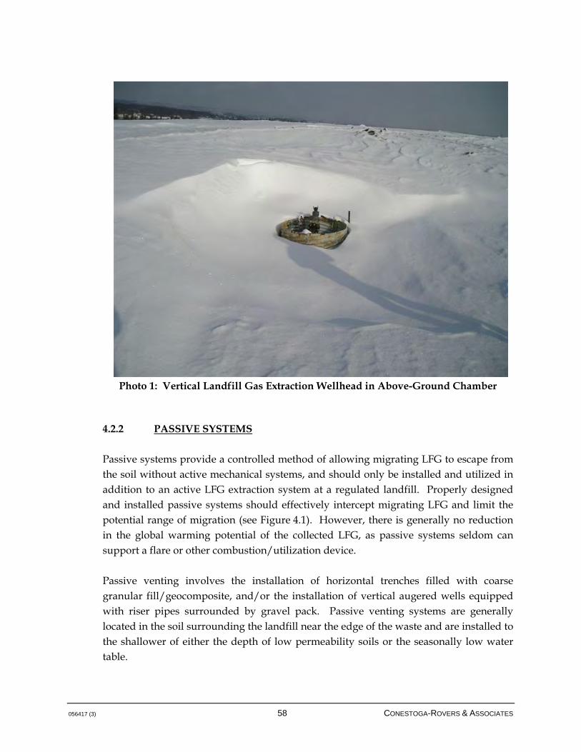
056417 (3) 58 CONESTOGA-ROVERS & ASSOCIATES
Photo 1: Vertical Landfill Gas Extraction Wellhead in Above-Ground Chamber
4.2.2 PASSIVE SYSTEMS
Passive systems provide a controlled method of allowing migrating LFG to escape from the soil without active mechanical systems, and should only be installed and utilized in addition to an active LFG extraction system at a regulated landfill. Properly designed and installed passive systems should effectively intercept migrating LFG and limit the potential range of migration (see Figure 4.1). However, there is generally no reduction in the global warming potential of the collected LFG, as passive systems seldom can support a flare or other combustion/utilization device. Passive venting involves the installation of horizontal trenches filled with coarse granular fill/geocomposite, and/or the installation of vertical augered wells equipped with riser pipes surrounded by gravel pack. Passive venting systems are generally located in the soil surrounding the landfill near the edge of the waste and are installed to the shallower of either the depth of low permeability soils or the seasonally low water table.
056417 (3) 59 CONESTOGA-ROVERS & ASSOCIATES
Passive systems rely on the slightly positive (relative to atmospheric) pressure of gas migrating through the soil to induce exhaust of gas to the atmosphere. Due to the very low gas pressures and flows expected, passive vent systems located outside the perimeter of the landfill are not generally capable of self-supporting and safe combustion of the vented gas.
The primary advantages of passive venting are lower capital costs, simplicity of construction, and minimal operating costs other than for periodic monitoring. The disadvantages of passive venting are that its effectiveness and applicability may be limited by soil conditions, and the LFG is released directly to the atmosphere from point sources, which may result in odours and degradation of air quality, and contribute to GHGs. Passive venting systems can also be incorporated underneath buildings, using granular layers beneath foundation works to collect migrating LFG and vent this LFG to the atmosphere via riser pipes equipped with vent turbines. If the migration assessment for the site indicates high potential for migration, this system may be connected to a blower that actively vents the collected LFG to the atmosphere depending on the concentration that develops in the collection/riser piping.
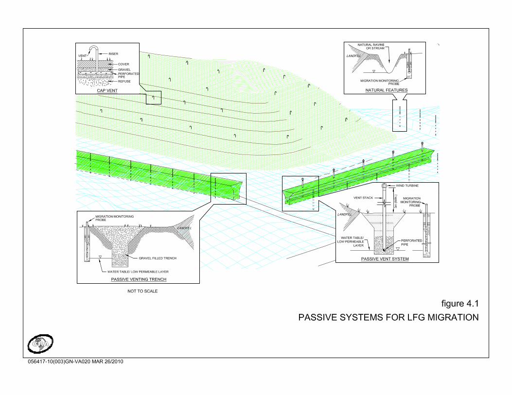
056417 (3) 61 CONESTOGA-ROVERS & ASSOCIATES
4.2.2.1 BARRIER SYSTEMS
A form of passive system that can be implemented to prevent migration of LFG through subsurface soils is a barrier system, which can be constructed in the soil adjacent to the edge of the landfill. Barrier systems include bentonite and soil slurry walls, cement slurry walls, curtains of concrete grout, sheet pile walls, synthetic membranes, and air pressure curtains. These systems have increased applicability and effectiveness over passive vents in some conditions, and have virtually no operating costs (with the exception of air pressure curtains) other than periodic monitoring. Baffle systems should include a passive venting system on the landfill side of the barrier to release LFG pressure that builds up in the soil. This is necessary to ensure the effectiveness of these systems in preventing lateral movement of gas rather than simply uncontrolled redirection of the LFG around or beneath the barrier. Bentonite and soil slurry walls are constructed by excavating a trench to a desired depth while concurrently backfilling with a relatively impermeable material such as a bentonite and slurry mixture to form a baffle. Construction of a sheet piling baffle involves installation of steel panels into the soil. Adjacent panels connect together with specialized interlocking joints to form a low permeable baffle to gas and water flow. Air curtains use the positive pressure of air continuously injected into the soil to counter-balance the pressures that cause migration of LFG. A blower or compressor is used to inject air into a series of wells or trenches located in the soil outside the limit of waste. These active mechanical systems require long-term expenditures for operation and maintenance, and the applicability of air curtains is generally limited to localized protection of buildings. Generally, with the increased versatility of active LFG collection systems, the applicability of barrier systems is somewhat limited.

056417 (3) 62 CONESTOGA-ROVERS & ASSOCIATES
5.0 LANDFILL GAS MANAGEMENT DESIGN
LFG management systems are constructed to suit one or more of the following purposes: Control subsurface migration of LFG from a landfill site
Collect LFG from the waste to control odours and/or emissions to the air
Collect LFG from the waste for use as a resource
LFG collection systems for odour and emissions control are similar to those for LFG utilization but the overall objectives differ and thus the specific requirements are quite different even if the physical elements are basically the same. For collection systems that are intended primarily to control odour and emissions, well spacing is increased and therefore coverage is minimized to collect only the LFG that is needed to get below the odour threshold. Such systems often also have a positive effect on controlling subsurface migration of LFG. The extent of this effect is highly dependent on the stratigraphy of the site. A typical LFG collection system comprises the following components: Collection field (vertical extraction wells and horizontal collection trenches)
Collection piping (laterals, subheaders, headers, etc.)
LFG extraction plant (including condensate trap, condensate knockout, and blower systems)
LFG disposal/destruction system (flaring and utilization)
Process control system
LFG management can be achieved through the use of these components and there is potential, through the development of the international carbon market, for this type of system to generate revenue through the creation of GHG emission reduction credits. In the BC context, early adoption of LFG management systems that are intended to reduce the global warming potential of methane offer real potential up unto the date of implementation of mandatory collection (January 1, 2016) as per the Regulation. Development of systems, utilizing the information within this Guideline, prior to this date can lead to potential sale of GHG emission reduction credits and the creation of a revenue stream to defer the costs of the system. The more robust and efficient the system, the greater will be the net revenue generated. The subject of this Guideline is the provision of performance standards and design guidance to motivate the
056417 (3) 63 CONESTOGA-ROVERS & ASSOCIATES
development of high efficiency LFG management systems specifically; developers may subsequently benefit from this by achieving high yields of GHG emission reductions and the associated revenues. Revenue provided by such systems creates an incentive for better landfill design and LFG management, and a contribution towards improvement of the overall waste management system. This Guideline recognizes that the design of LFG management systems must permit flexibility for designers to respond to site-specific considerations such that innovative design approaches can be developed. The field of LFG management system design continues to evolve, and the range of designs varies with differences in landfills and landfill management practices. For this reason, the below design guidance is intended to provide reasonable best management practices and considerations for designers to ensure that the design and performance standards identified in this document can be achieved. As an additional design standard: Design Standard 4 This leads to subsurface piping being sized for the total potential flows and prevents flow constrictions subsequently as LFG volumes increase; generally, it is far more efficient to install piping, conveyance, and condensate systems during the initial capital works than it is to subsequently retrofit an undersized design. It may be impractical, depending on the LFG generation profile, to size flare capacity and mechanical systems such as blowers for the ultimate LFG generation, so some judgment is required in this area. Flares and mechanical equipment such as blowers must be sized based on economics and based on the design standard of 75 collection efficiency (Design Standard 2, Section 3.1),outlined in this Guideline. Also note the following general design standard:
LFG management systems will be designed to accommodate the maximum LFG generation expected, rather than the expected LFG collection.

056417 (3) 64 CONESTOGA-ROVERS & ASSOCIATES
Design Standard 5 The design standard above illustrates the requirement to collect LFG using an active LFG management system such that LFG can be combusted using high-efficiency enclosed flares, or in utilization systems as long as the global warming potential of methane in the LFG is reduced. The intent of this design standard is not, however, to restrict utilization options such as pipeline upgrades or formulation of chemical products such as methanol as long as it can be demonstrated that a net global warming reduction of methane is achieved. Passively emitting LFG to the atmosphere for any system configuration does not meet the above design standard. Passive venting systems for localized areas of waste may be warranted depending on local conditions; however, the main waste mass is required by the Regulation to be under active LFG control with a means of reducing the global warming potential of methane by converting it to carbon dioxide using a proven technology. As mentioned in Section 1.1, it should be noted that there are other potential design requirements that must be observed, irrespective of this Guideline. This document has been compiled in general accordance with CAN/CGA-B105-M93, the Canadian Gas Association's "Code for Digester Gas and Landfill Gas Installations." This standard and all other applicable standards should be consulted for specific information and requirements when engaging in the design of LFG management systems and the practitioners should seek to remain abreast of additional design requirements as they emerge. 5.1 COLLECTION FIELD
The collection field consists of a network of vertical LFG extraction wells and/or horizontal LFG collection trenches installed in the waste to collect the LFG. The basic operating principle is quite simple: a vacuum is applied to extract the gases from the waste mass as closely matched to the rate at which the gas is being generated within the influence area of the vertical LFG extraction well or horizontal LFG collection trench as is practical. The idealized target objective is to establish a neutral pressure/vacuum gradient continuously over the entire surface of the landfill. Figures 5.1 and 5.2 provide
All LFG captured must undergo a reduction in global warming potential as it relates to the methane component of the gas (i.e. flaring, LFG utilization for electricity generation, fuel for vehicles, etc.). Refer to Section 9 of the Regulation for more information.
056417 (3) 65 CONESTOGA-ROVERS & ASSOCIATES
a typical vertical extraction well detail for above ground and below ground designs, respectively. Figures 5.3 and 5.4 provide a typical horizontal collection trench cross-section and detail, respectively. The arrangement of wells or trenches on the site should be designed to include as much of the waste as possible within their capture zones. The capture zone may be considered as that portion of the waste in which a negative pressure may be induced by application of a vacuum at the well or trench head. This is a somewhat conservative interpretation, as a portion of the LFG outside the negative pressure zone will tend to move towards the well or trench as a result of the pressure differential that develops. This conservatism is justified, however, because some component of the gas outside the negative pressure zone will be expected to vent to the atmosphere rather than to migrate into the capture zone.


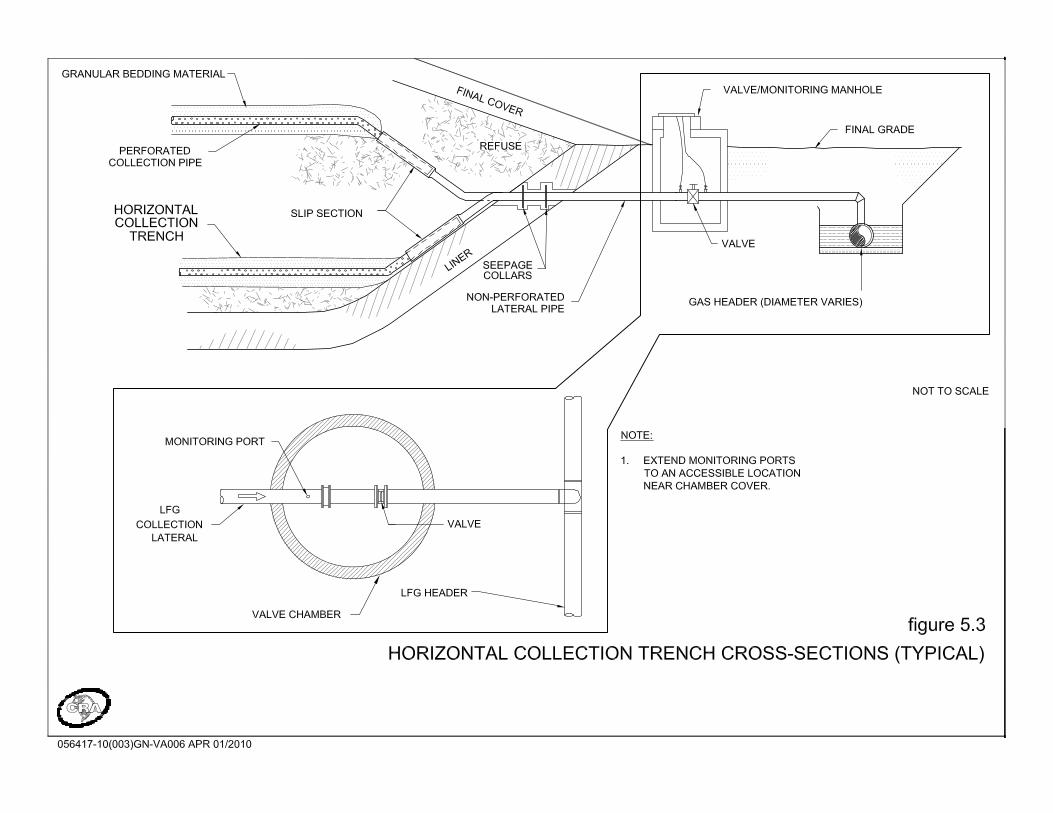

056417 (3) 70 CONESTOGA-ROVERS & ASSOCIATES
The zone of negative pressure influence is highly variable from site to site and may vary from location to location within a site. A number of variables will affect the size of the capture zone that may be established. These include the following: Practical limitations on vacuum that may be applied
Horizontal and vertical transmissivity of the wastes
Depth to static leachate and the presence of leachate mounds, perched or otherwise
Daily, intermediate, and final cover types
Site configuration
As a general rule, where collection efficiency is important, it is generally advisable to develop a tighter grid of extraction points that is operated at lower vacuum rather than to install a system with larger spacing between wells where this latter condition requires operating at higher vacuum. This is a best management practice that can be applied economically to LFG systems if the design is developed to achieve other efficiencies such as narrower-diameter wells. It has been found that a vacuum of 10 to 25 inches of water column (in WC) represents a reasonable compromise between maximizing zones of influence and minimizing air intrusion into the site, while using economical LFG extraction equipment. Capture zones that may be achieved by applying vacuum in this range are highly variable. The radius of the capture zone from the well may range from less than 20 m (65 ft) up to 60 m (195 ft), and is strongly dependent on localized conditions. The performance of each vertical extraction well or horizontal collection trench is based on a flow-vacuum relationship that is additionally influenced by the landfill conditions that affect generation and recovery. For example, a vertical extraction well in older waste will be reasonably expected to produce less LFG per unit vacuum. Another vertical extraction well in an area of fresher waste may generate much greater LFG flow even if it is operated at lower total vacuum because of, for instance, a permeable cover soil. Generally, recovery per vertical extraction well is in the range of 25 to 75 m3/hr (15 to 45 cubic feet per minute [cfm]); for horizontal collection trenches, typical recovery is in the range of 12 to 18 m3/hr (7 to 10 cfm) per 100 m (328 ft) of horizontal collection piping. Again, these are typical rates, and the local landfill conditions and design and construction details strongly influence the actual recovery, as does the operational practice of the LFG management system.

056417 (3) 71 CONESTOGA-ROVERS & ASSOCIATES
In terms of best management practice, it is generally advisable to design LFG management systems to incur relatively small pressure drops from the LFG blower to the LFG collection field. Typically, systems are designed to exert at least 15 in WC on all vertical extraction wells or horizontal collection trenches, with the opportunity to increase vacuum to at least twice that level if required. Overall pressure drop through the system due to frictional and minor losses should generally be in the range of less than 10 in WC. Design of a system to run at high pressure drops is generally inefficient, requiring larger blowers and providing less redundancy where increased future flows may be realized. Additionally, running at higher vacuum tends to stress the LFG collection field by pushing the zone of capture beyond the waste matrix, increasing the potential for atmospheric air intrusion. Generally, either horizontal or vertical gas extraction systems are utilized; in some situations, a combination of both is used. Given the mandate of this Guideline, which reflects the requirements of the Regulation to control LFG at active sites, it is expected that systems comprising both components will be required to satisfy the overall performance standards identified herein; specifically, capture of LFG from active areas of the landfill is best accomplished using horizontal extraction collection systems, while closed portions of the landfill are generally best addressed using vertical extraction systems. Horizontal collection trenches are generally installed at sites where controlling LFG emissions during the site filling period is a priority. An advantage of a horizontal collection system over a vertical extraction system is that it can collect LFG from beneath active areas of sites still being filled, where vertical extraction wells cannot. However, the horizontal collection trenches are not as suitable for localized area control. Horizontal collection trenches will typically be installed at depth within a large landfill. The horizontal collectors will be subject to extremes of differential settlement since they extend laterally over portions of a site that may have different types, depths and age of waste. Horizontal collection trenches can be thought of as disposable collection infrastructure. Vertical LFG extraction wells are typically installed in a landfill once filling operations have been completed, and exert a radial zone of influence around the well bores. These systems can be prone to issues around landfill settling and the overall design of vertical extraction wells should be undertaken with full understanding of leachate levels, depth to liner, daily/intermediate cover practices, and the practicality of extracting LFG from consolidated areas of waste at depth.
056417 (3) 72 CONESTOGA-ROVERS & ASSOCIATES
5.1.1 HORIZONTAL COLLECTION TRENCH DESIGN CONSIDERATIONS
Horizontal collection trenches consist of a perforated pipe in appropriate granular bedding material, which is placed in a trench within the waste. The trench may be excavated into the upper portion of a lift of waste. Alternately, the trench may be constructed by first stripping any cover soil from the top of the waste surface, then building a gravel trench containing the collection pipe and overfilling the trench with fresh waste. The horizontal collection pipe may be a continuous run of pipe or may be segmented. The segmented approach, using two sizes of pipe with the segments overlapping, is preferred as it provides additional flexibility, especially with respect to accommodating differential settlement of waste. Some depth of granular bedding material should be provided below the pipe to allow for drainage of liquids from the trench and above the pipe for enhanced LFG collection. Horizontal collection trenches should be installed at a high enough elevation in the waste to avoid flooding by mounded leachate. At sites where perched leachate conditions are prevalent, drainage of trenches may be enhanced by excavation or drilling of sumps or infiltration sinks at intermediate locations along the trench alignment. Trench laterals can be equipped with telescoping sections of non-perforated pipe at the edge of the site to account for settlement movement; fused HDPE pipe has also been used for horizontal extraction. As with vertical wells, individual trenches should also be equipped with valves and monitoring ports to allow for monitoring and control of the applied vacuum. Horizontal collection trenches are installed at various depths within the waste as filling progresses. Trenches must be installed in a manner that is compatible with filling operations at the site. This is best achieved by aligning the trenches with waste placement. For example, if a rectangular cell has its longest side in a north-south direction, waste will typically be placed in a north-south direction until a lateral move to the east or west is required to permit additional waste capacity. The horizontal collection trenches will be placed in the north-south direction, parallel to the placement of waste. One disadvantage associated with the use of horizontal collection trenches is the difficulty of arranging a trench network at sites with irregular configurations. The horizontal distance between trenches should be in the range of 15 to 30 m; the correct spacing should be identified on a site-specific basis to address the overall

056417 (3) 73 CONESTOGA-ROVERS & ASSOCIATES
performance standards identified in this Guideline. This spacing is additionally a function of filling rate, where larger spacing may be sufficient for larger sites with higher filling rates. The vertical distance between trenches should be less than the horizontal spacing. This is due to the fact that the horizontal permeability of waste may be as much as ten times greater than the vertical permeability. Vertical spacing between trenches should be in the range of 10 to 20 m, and nominally is set at 12 m. The depth of soil/waste cover over a collection trench is an important consideration in designing the collection field layout. As with vertical wells, 3 to 6 m (10 to 20 ft) of site depth should be maintained over the expected capture zone of a trench; evaluation of the optimal depth should be made according to leachate levels and the characteristics of the final cover. Given the vertical and horizontal spacing set for horizontal piping, it is important to have an understanding of leachate conditions and the potential effects on the LFG system. Where horizontals are placed above the level of the header system, any intercepted leachate will be conveyed to the header piping so long as the piping is not sloped back into the landfill. While this may be an inevitable result of the horizontal collection system development, it is important to understand that the LFG collection system will thus be subject to leachate, and that condensate traps and other systems for removing liquid should be designed with this in mind. Liquid handling in this situation will be critical to the operation of the LFG collection system. In some cases, where leachate levels are high, horizontal collection trenching may be appropriate for closed portions of sites. Development of vertical extraction wells in areas of high leachate levels may significantly affect the productivity of these wells. Horizontal collection trenches can be utilized in these areas to install shallow systems, but must be developed with full understanding that shallow systems can potentially be subject to air intrusion depending on cover conditions and the exerted vacuum. Vertical extraction well and horizontal collection trench components that are in contact with LFG, condensate, waste, or leachate should be constructed of materials that are chemically resistant to the potentially aggressive compounds present. A number of economical plastic materials are available that have proven success in landfill applications. Two of the most common are polyvinyl chloride (PVC) and high density polyethylene (HDPE). HDPE is the most common material type used in LFG management systems. Note that the overall pressure drops along horizontal collection piping are variable, as gas is influent to the piping at different locations. The maximum pressure drops are
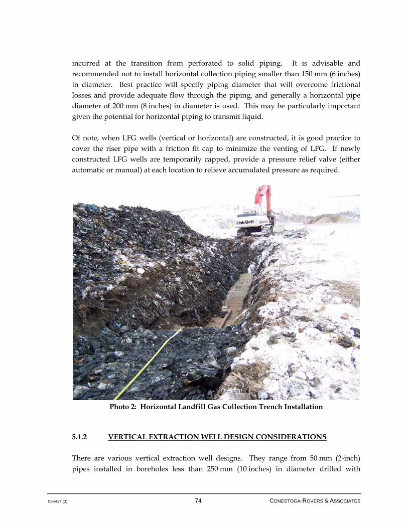
056417 (3) 74 CONESTOGA-ROVERS & ASSOCIATES
incurred at the transition from perforated to solid piping. It is advisable and recommended not to install horizontal collection piping smaller than 150 mm (6 inches) in diameter. Best practice will specify piping diameter that will overcome frictional losses and provide adequate flow through the piping, and generally a horizontal pipe diameter of 200 mm (8 inches) in diameter is used. This may be particularly important given the potential for horizontal piping to transmit liquid. Of note, when LFG wells (vertical or horizontal) are constructed, it is good practice to cover the riser pipe with a friction fit cap to minimize the venting of LFG. If newly constructed LFG wells are temporarily capped, provide a pressure relief valve (either automatic or manual) at each location to relieve accumulated pressure as required.
Photo 2: Horizontal Landfill Gas Collection Trench Installation
5.1.2 VERTICAL EXTRACTION WELL DESIGN CONSIDERATIONS
There are various vertical extraction well designs. They range from 50 mm (2-inch) pipes installed in boreholes less than 250 mm (10 inches) in diameter drilled with

056417 (3) 75 CONESTOGA-ROVERS & ASSOCIATES
conventional drilling rigs, to 200 mm (8-inch) pipes installed in large diameter (600 to 900 mm) (24- to 35-inch) holes drilled with caisson-type drilling rigs. There is no significant benefit from using the much costlier large diameter wells, as the density and viscosity of LFG does not support the contention, as it does for groundwater wells, that increased diameter of well necessarily results in greater volumes of extracted product. There has been ample operational evidence to suggest that narrow diameter wells (down to 75 mm [3-inch] and even 50 mm [2-inch] diameter in narrow boreholes) perform well over the long term at a reduced drilling cost. The ability to develop a greater number of extraction points rather than larger individual extraction points is a further means of improving overall control of a LFG collection system and its system efficiency. One of the only situations that merits consideration of larger-diameter vertical extraction wells is where leachate is present in perched conditions due to fire breaks or presence of impermeable daily cover; larger wells can, in this situation, aid in the drainage of perched layers, but overall best management practice does not support the use of fire breaks or cover soil application that leads to perched conditions. If impermeable daily and/or intermediate cover is used at the site, this cover soil should be stripped off before the next lift of waste is placed to avoid perched conditions. Impermeable cover includes clayey soils, especially fine clays. Daily and intermediate cover that may not require removal would be sandy or gravelly material due to the higher permeability characteristics of these materials compared to clay material. Typically, the limiting design factors are the maximum applied vacuum and the maximum quantity of gas that each well may have to extract. In most instances, a properly designed and installed small-diameter LFG well provides more than adequate capacity with a substantial margin of safety, and at reduced cost. The LFG collection field design should also consider the frictional losses of the design. Vertical extraction wells are typically installed within a borehole that is augered into the solid waste. Wells should be installed to the higher of 3 to 5 m (10 to 16.5 ft) from the bottom of the waste, or the standing head of leachate. Under no circumstances is it advisable to have a vertical well affect the landfill liner system, and nor is it productive to place vertical extraction well screen beneath static liquid levels, as the induced vacuum is not likely to draw LFG through standing liquid head. Generally, the use of vertical extraction wells at significant depths in waste is counter-productive and inefficient. Typically, it is best practice to install wells at no more than 20 m (65 ft) into the waste, with acceptable provision as noted above for avoiding the landfill liner. However, deeper wells may be beneficial in areas where
056417 (3) 76 CONESTOGA-ROVERS & ASSOCIATES
there are perched leachate conditions and/or fire breaks, or other relevant site conditions. In deeper areas of waste, the following considerations adversely affect the efficiency of deep vertical wells: • Higher overall cost for drilling to greater depths
• More consolidated waste that offers less permeability to gas flow
• Overall flow hydraulics that will exert the majority of the well vacuum at lesser depths, where resistance to flow is reduced
• Older waste that has already undergone some level of off-gassing
• Potentially saturated waste that offers limited ability for LFG extraction
The vertical LFG extraction well consists of a collection pipe within a gravel pack. The lower portion of the pipe is perforated (or slotted) to collect LFG. The upper 4 to 6 m (13 to 20 ft) of the pipe is generally constructed of non-perforated pipe to limit the potential for atmospheric air intrusion; perforations too close to the landfill surface can significantly alter the radius of influence around the vertical extraction well and negatively affect the LFG composition by drawing in atmospheric air. In some situations, where synthetic cover systems are used, the length of non-perforated pipe may be shortened. The depth to perforations should be increased for wells in close proximity to side slopes; the depth to perforations should be selected to ensure that the capture zone does not fall within the required cover depth (4 to 6 m [13 to 20 ft]) at the side slope of the site. This will be dependent upon the radius of influence expected, the degree of slopes on the site and the cover material. A bentonite, or other type of low permeable seal, is usually placed in the borehole just above the transition from perforated to non-perforated pipe and generally extends over at least a 1 m (3 ft) interval. This also aids in limiting the drawing of air into the site by sealing the borehole annulus. The effectiveness of this seal is a critical item related to the efficiency of the LFG management system; if air is allowed to intrude through the borehole annulus, this will diminish the effective radius of influence, resulting in a decrease in LFG capture and an increase in release to the atmosphere. The wells are perforated in the lower reach with holes (or slots) that are smaller than the diameter of the gravel used in the annular space. An example is the use of 6 mm (1/4-inch) diameter openings in a well where 10 mm (3/8-inch) pea gravel is used. Of note, perforations that are drilled often leave detritus within the well pipe; it is best management practice to remove these burrs and other debris in order to prevent blockage of perforations, especially as mineral deposits take root on the debris.
056417 (3) 77 CONESTOGA-ROVERS & ASSOCIATES
Each vertical extraction well should be equipped with appropriate monitoring ports to allow monitoring of gas concentrations, temperature, flow rate, static pressure, and liquid level with field equipment. There is no need for dedicated monitoring equipment at each individual well. Each well should be further equipped with a valve to allow individual adjustment and modification of the vacuum levels applied on the waste. In some cases, it is recommended that the well head, including the monitoring ports and valve, be enclosed within a lockable chamber. This will discourage tampering and vandalism, and will minimize damage due to severe weather conditions. The vertical extraction well should be designed to accommodate the extreme settlement usually associated with landfills. The vertical riser pipe may be equipped with a telescoping section to address differential settlement of waste over time; essentially, the upper component of the well is allowed to slip into the lower portion over time as the landfill surface subsides. Laterals to well heads are often equipped with a length of flexible hose. This is to allow movement in response to shear and axial forces applied to the pipe by the differential settlement of the landfill. Well spacing of anywhere from 40 to 120 m (130 to 390 ft) between wells is appropriate, and is largely a function of the various landfill conditions. If landfill cover is poor, or high leachate levels require a shallow system, spacing may be reduced in order to exert less vacuum on the individual wells. In the presence of synthetic covers, well spacing may be increased and vacuum levels elevated. Generally, the objectives of the LFG management system play a significant part in determining the optimal well spacing, and sites where LFG utilization is considered or where a higher LFG collection efficiency is required, a tighter well spacing may be warranted in order to maximize recovery. It is also noted that the initial development of a LFG collection field utilizing vertical extraction wells should be supplemented by infilling as required to satisfy performance standards and utilization system fuel requirements. As waste ages, the proportional LFG generated per unit area of landfill surface diminishes. Exerting excess vacuum is not necessarily the appropriate response to this, given that such elevated vacuum may encourage intrusion of atmospheric air. Infilling of the vertical extraction well field with additional vertical extraction points is a more reasonable approach to maximizing LFG recovery. Additionally, it should be noted that a landfill is essentially a biological entity that is subject to a variety of forces and settlement pressures that can have a profound effect on installed systems. It is expected that some wells will fail over time, requiring replacement in order to maintain reasonable efficiencies.
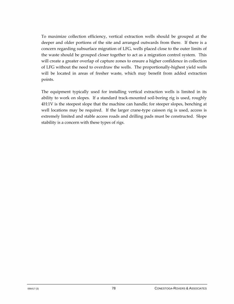
056417 (3) 78 CONESTOGA-ROVERS & ASSOCIATES
To maximize collection efficiency, vertical extraction wells should be grouped at the deeper and older portions of the site and arranged outwards from there. If there is a concern regarding subsurface migration of LFG, wells placed close to the outer limits of the waste should be grouped closer together to act as a migration control system. This will create a greater overlap of capture zones to ensure a higher confidence in collection of LFG without the need to overdraw the wells. The proportionally-highest yield wells will be located in areas of fresher waste, which may benefit from added extraction points. The equipment typically used for installing vertical extraction wells is limited in its ability to work on slopes. If a standard track-mounted soil-boring rig is used, roughly 4H:1V is the steepest slope that the machine can handle; for steeper slopes, benching at well locations may be required. If the larger crane-type caisson rig is used, access is extremely limited and stable access roads and drilling pads must be constructed. Slope stability is a concern with these types of rigs.

056417 (3) 79 CONESTOGA-ROVERS & ASSOCIATES
Photo 3: Vertical Landfill Gas Extraction Well Drilling and Installation
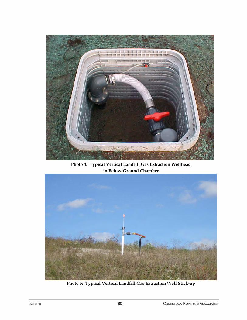
056417 (3) 80 CONESTOGA-ROVERS & ASSOCIATES
Photo 4: Typical Vertical Landfill Gas Extraction Wellhead
in Below-Ground Chamber
Photo 5: Typical Vertical Landfill Gas Extraction Well Stick-up
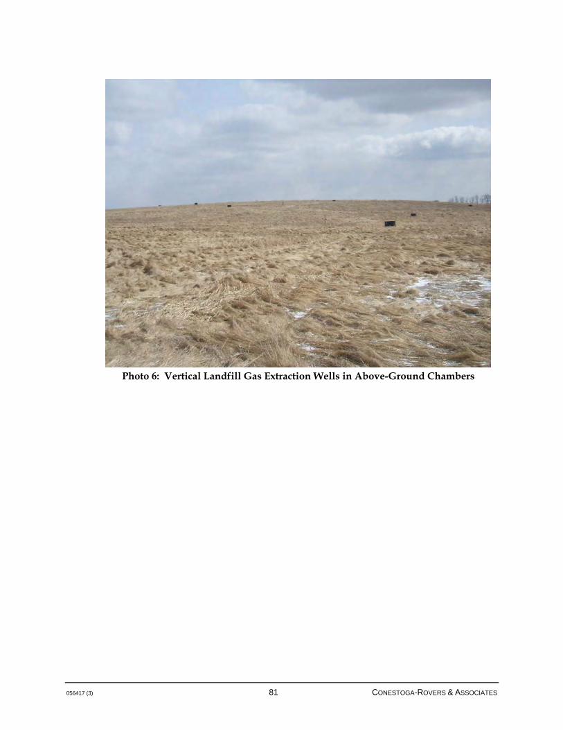
056417 (3) 81 CONESTOGA-ROVERS & ASSOCIATES
Photo 6: Vertical Landfill Gas Extraction Wells in Above-Ground Chambers
056417 (3) 82 CONESTOGA-ROVERS & ASSOCIATES
5.1.3 COLLECTION PIPING
Collection piping consists of a network of pipes constructed to connect the LFG collection field to the LFG flare or utilization plant (see Figure 5.5). A typical LFG collection system includes the following: Small diameter (minimum 100 mm [4-inch]), short laterals connecting the
wells/trenches
Subheaders that connect the laterals
Headers that transport LFG from the subheaders to the extraction plant
Generally, piping diameters increase with proximity to the LFG blower in order to accommodate the higher volumes of collected LFG. Per the performance standard already noted in this Guideline, design of the transmission system to accommodate the peak LFG generation, rather than expected collection, is an important component of ensuring that the transmission system is suitably designed from the onset. It is equally important as a best management practice to ensure that portions of the LFG collection system can be isolated as required. This facilitates shutting off various portions of the system to respond to maintenance issues, inspections, repairs, and system expansion, without having to shut down the entire collection system. Where performance standards require high efficiency systems, the ability to respond to issues while enabling continued LFG management system uptime is important and should be part of the design basis. This can include, for example, valving not only at individual wells and horizontals, but at subheader tie-ins to the main header system. In addition to isolating portions of the field, a best management practice is to ensure adequate monitoring locations. It has already been discussed that wells should be equipped with their own valving and monitoring ports. Subheader isolation valves should also be equipped with monitoring ports. This greatly facilitates operations, as a preliminary round of monitoring at subheader connections to the header can rapidly identify a problematic section of the field for further attention and balancing as required. Several LFG network piping patterns are designed to facilitate the drainage of liquids and minimize the length of pipe required for the collection system. Common arrangements of collection piping make use of either a "herringbone" or a "ring" layout as shown in Figures 5.5. These are intended to convey broad categories of network

056417 (3) 83 CONESTOGA-ROVERS & ASSOCIATES
piping; alternative or hybrid design are certainly possible and must be evaluated against site-specific conditions and considerations. Note that in any configuration, particular attention should be paid to the transition zone between where collection piping is placed in waste and where it resides on more competent strata at the perimeter of the landfill. As waste settles, it can reasonably be expected that these areas will become stressed, and adequate measures should be designed into the system to accommodate settling-related stresses.


056417 (3) 85 CONESTOGA-ROVERS & ASSOCIATES
Ring Header Layout A ring header located within the waste discharge area may be used when there is insufficient land available for construction of a header system outside the waste discharge area. In this scenario, the ring header offers the advantage of flexibility, allowing gas to be drawn through either side of the header, providing some redundancy in the case of pipe blockage. Use of a ring header (either inside or outside the waste discharge area) located outside the well field is one method of collecting all the condensate that forms in the piping. A ring header located outside the waste discharge area, affords the operational flexibility associated with ring headers and reduces some of the problems associated with placement of piping on waste (i.e., differential settlement). LFG collection piping placed outside the waste discharge area is typically buried below the frost line. Some sites have clay or synthetic liners that require pipe crossings. Ring headers should be equipped with isolation valves to allow segregation of portions of the site, and monitoring ports to monitor gas quality and quantity. Dual header systems have been utilized at some large and deep landfill sites that have a long active site life to segregate the methane-rich gas from the deeper portions of the site from the gas collected from near the surface that may be diluted via air intrusion (see Figure 5.6); however, this is not common practice. Numerous design criteria/constraints have been developed relating to the piping installations and specifying items such as minimum and maximum slopes, condensate moisture removal, differential and total settlement stresses, and dead and live load stresses. Herringbone Ring Layout A traditional herringbone arrangement has single or multiple subheaders that run laterally across the site and connect to a main header that transports the LFG to the extraction plant. A herringbone ring arrangement is a combination of a herringbone and ring layout, where a set of subheaders are placed laterally across the site and are connected to a ring header that surrounds the site (see Figure 5.5). Wells are grouped to facilitate drainage along the subheader or lateral alignment. Piping alignments are chosen to provide the most direct routing that maximizes the slope of the pipe. Particular care should be taken to avoid creating low spots in the piping. Piping cleanouts can be located at the termination of subheaders and along header piping as shown in Figure 5.7.

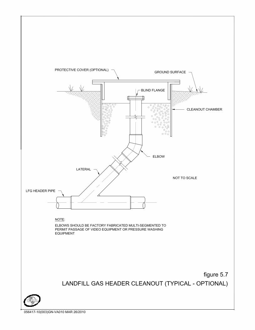

056417 (3) 88 CONESTOGA-ROVERS & ASSOCIATES
The herringbone ring arrangement may also be used with a header located outside the waste discharge area. This reduces the quantity of piping that must be located on waste but may increase the quantity of condensate that is generated. Use of a header located outside the waste discharge area requires a reasonable grade along the alignment outside the waste for gravity drainage or construction of condensate pumping stations. The advantage of the herringbone ring layout is the increased level of redundancy (i.e., laterals running across the site connecting to ring header on either side of site). A simple ring header does not have this redundancy as the subheaders terminate at the highest well. If a subheader fails, the wells beyond the point of failure will no longer collect LFG. A herringbone ring layout can draw from either side of the landfill site. The optimal collection piping layout is dependant on the specific characteristics and limitations of each individual site, and many usable configurations and arrangements can be suited to the individual conditions. Factors such as type of refuse, available space, material costs, landfill design, and operations are some of the many issues to consider when selecting a collection piping layout. Table 5.1 presents a summary comparison of the major features associated with the different piping arrangements. Note that it is possible to create a collection piping arrangement that utilizes above grade piping. This can be an economical way to install a LFG collection system as long as thermal issues are addressed. In cold climates, exposed LFG piping can lead to freezing of condensate and the development of blockages. In warmer climates, temperature in exposed HDPE piping can increase significantly. Additionally, above-grade piping can present security and safety issues depending on the current and future expected uses of the landfill. One potential means of dealing with thermal issues is to develop above ground berms to cover piping, but the use of this technique should be carefully evaluated against the above-noted concerns and stormwater/surface water management concerns.
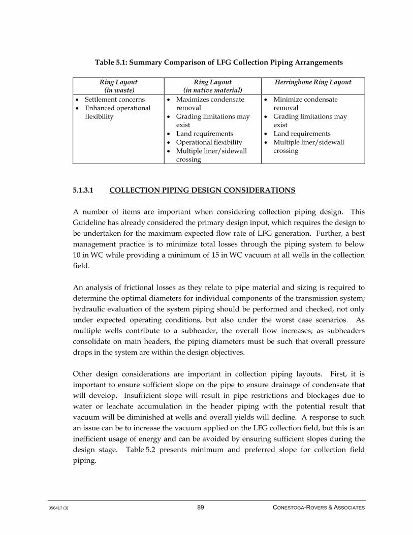
056417 (3) 89 CONESTOGA-ROVERS & ASSOCIATES
Table 5.1: Summary Comparison of LFG Collection Piping Arrangements
Ring Layout (in waste)
Ring Layout (in native material)
Herringbone Ring Layout
Settlement concerns Enhanced operational
flexibility
Maximizes condensate removal
Grading limitations may exist
Land requirements Operational flexibility Multiple liner/sidewall
crossing
Minimize condensate removal
Grading limitations may exist
Land requirements Multiple liner/sidewall
crossing
5.1.3.1 COLLECTION PIPING DESIGN CONSIDERATIONS
A number of items are important when considering collection piping design. This Guideline has already considered the primary design input, which requires the design to be undertaken for the maximum expected flow rate of LFG generation. Further, a best management practice is to minimize total losses through the piping system to below 10 in WC while providing a minimum of 15 in WC vacuum at all wells in the collection field. An analysis of frictional losses as they relate to pipe material and sizing is required to determine the optimal diameters for individual components of the transmission system; hydraulic evaluation of the system piping should be performed and checked, not only under expected operating conditions, but also under the worst case scenarios. As multiple wells contribute to a subheader, the overall flow increases; as subheaders consolidate on main headers, the piping diameters must be such that overall pressure drops in the system are within the design objectives. Other design considerations are important in collection piping layouts. First, it is important to ensure sufficient slope on the pipe to ensure drainage of condensate that will develop. Insufficient slope will result in pipe restrictions and blockages due to water or leachate accumulation in the header piping with the potential result that vacuum will be diminished at wells and overall yields will decline. A response to such an issue can be to increase the vacuum applied on the LFG collection field, but this is an inefficient usage of energy and can be avoided by ensuring sufficient slopes during the design stage. Table 5.2 presents minimum and preferred slope for collection field piping.
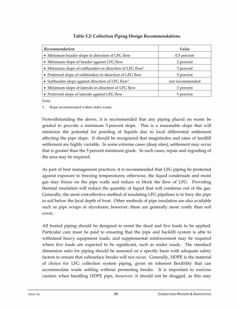
056417 (3) 90 CONESTOGA-ROVERS & ASSOCIATES
Table 5.2: Collection Piping Design Recommendations
Recommendation Value
Minimum header slope in direction of LFG flow 0.5 percent
Minimum slope of header against LFG flow 2 percent
Minimum slope of subheaders in direction of LFG flow1 3 percent
Preferred slope of subheaders in direction of LFG flow 5 percent
Subheader slope against direction of LFG flow1 not recommended
Minimum slope of laterals in direction of LFG flow 3 percent
Preferred slope of laterals against LFG flow 5 percent
Note:
1. Slope recommended within older waste.
Notwithstanding the above, it is recommended that any piping placed on waste be graded to provide a minimum 5 percent slope. This is a reasonable slope that will minimize the potential for ponding of liquids due to local differential settlement affecting the pipe slope. It should be recognized that magnitudes and rates of landfill settlement are highly variable. In some extreme cases (deep sites), settlement may occur that is greater than the 5 percent minimum grade. In such cases, repair and regrading of the area may be required. As part of best management practices, it is recommended that LFG piping be protected against exposure to freezing temperatures; otherwise, the liquid condensate and moist gas may freeze on the pipe walls and reduce or block the flow of LFG. Providing thermal insulation will reduce the quantity of liquid that will condense out of the gas. Generally, the most cost-effective method of insulating LFG pipelines is to bury the pipe in soil below the local depth of frost. Other methods of pipe insulation are also available such as pipe wraps or styrofoam; however, these are generally more costly than soil cover. All buried piping should be designed to resist the dead and live loads to be applied. Particular care must be paid to ensuring that the pipe and backfill system is able to withstand heavy equipment loads, and supplemental reinforcement may be required where live loads are expected to be significant, such as under roads. The standard dimension ratio for piping should be assessed on a specific basis with adequate safety factors to ensure that subsurface breaks will not occur. Generally, HDPE is the material of choice for LFG collection system piping, given its inherent flexibility that can accommodate waste settling without promoting breaks. It is important to exercise caution when handling HDPE pipe, however; it should not be dragged, as this may

056417 (3) 91 CONESTOGA-ROVERS & ASSOCIATES
cause damage and accumulate debris, and it is important to generally prevent the accumulation of dirt/granular material within the pipe during installation. Generally, the overall header sloping will be undertaken to observe minimum required slopes and provide drainage of condensate collected from the subheader and lateral systems. Within this overall objective is the requirement to ensure sufficient cover to prevent freezing conditions. The confluence of these factors generally requires careful thought when laying out header systems to manage not only the transmission of LFG but the conveyance of liquids. In some situations, this may require a sawtooth profile for the header system. Low spots in the header system will require some method of draining the piping. This can be accomplished using condensate traps with gravity drains or pump stations. Gravity drains may be constructed that allow accumulated liquid to drain back into the landfill or into a leachate collection system connection (see Figure 5.8). At sites with perched or mounded leachate conditions, gravity drainage of condensate back into the landfill is not generally recommended. Particular care should be taken in designing condensate drains to ensure that they are able to withstand the system operation vacuum, and a sufficient factor of safety should be included in the design to resist pressures applied as a result of system start-up and shutdown. It is also important to prevent p-traps or other condensate removal mechanisms from backing-up into the collection piping, as this is contrary to the goal of condensate removal and will introduce blockages into the LFG piping system. A condensate sump with pump station can be installed if a gravity drain cannot be constructed (see Figure 5.9). The condensate can be collected in a sump and pumped to a discharge point or to the next high point in the header, where it may be allowed to re-enter the LFG piping. In some cases a condensate holding tank (see Figure 5.10) may be used. A further aspect of best management practice is the consideration of LFG header cleanouts. LFG cleanouts may be considered in the collection piping design, but proper grade control will provide a limited need to access the LFG header. Best management practice will dictate access be provided regardless of necessity. In vertical extraction well systems, liquid flow will be limited to condensate (i.e., no leachate is transmitted into the collection system), so flushing of the lines will not be required. If horizontals are incorporated into the system, leachate could be introduced into the system from an upper tier of horizontals. However, if the horizontals are placed in the vadose zone of the waste, leachate flows should be minimized. Cleanouts can also facilitate camera
056417 (3) 92 CONESTOGA-ROVERS & ASSOCIATES
inspection of header systems as required, but again, if proper grade control and bedding is utilized during construction, the requirement for either cleanouts or inspections is somewhat minimized; practitioners may choose to include such systems in any case. Overall, it is vital to ensure that the collection system is designed appropriately, but it is equally important to construct the system with proper controls and interconnection of piping lengths to prevent leaks. Generally, the greatest concern with leaks related to subsurface LFG collection piping relates not to the emission of LFG, but to the intrusion of air as response to the induced vacuum. This diminishes vacuum on the well field and increases the oxygen/decreases the methane content of the LFG stream. Such conditions can be identified during operations by having a reasonable number of monitoring locations not only at the wells but also at subheaders and condensate traps. A best management practice related to the construction of the LFG management system is pressure testing of the subsurface piping system; this is a standard procedure and should be undertaken prior to backfilling the piping system if possible.
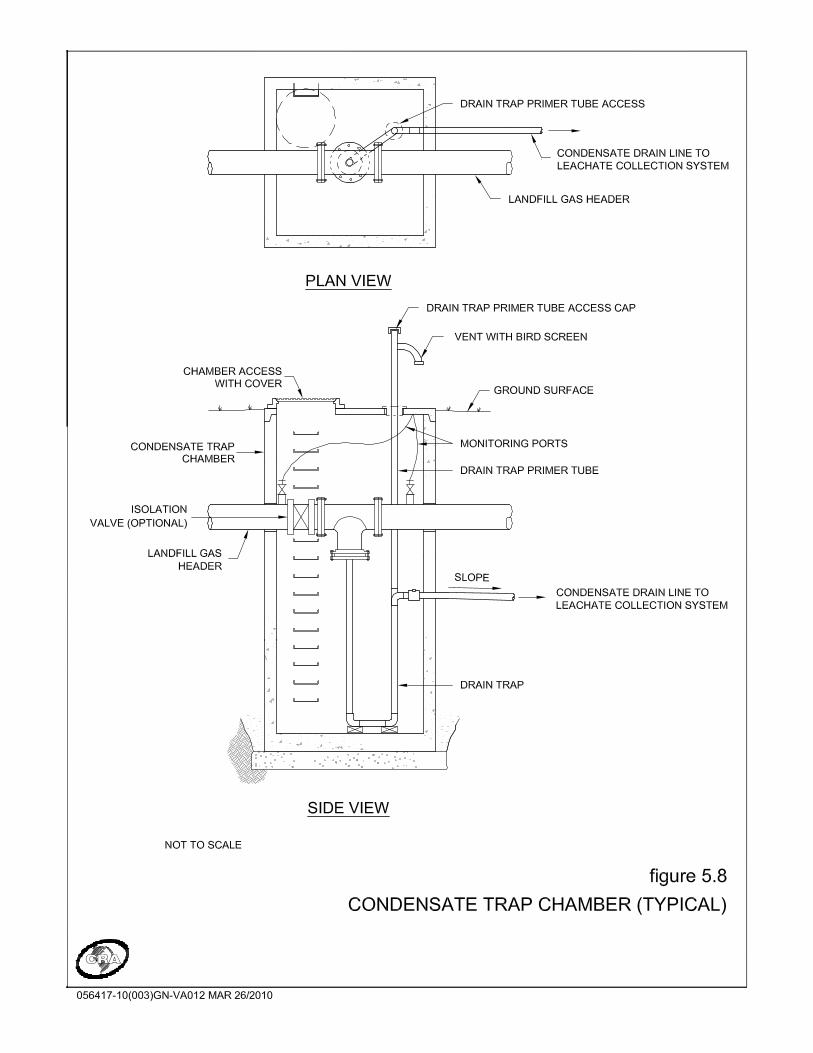

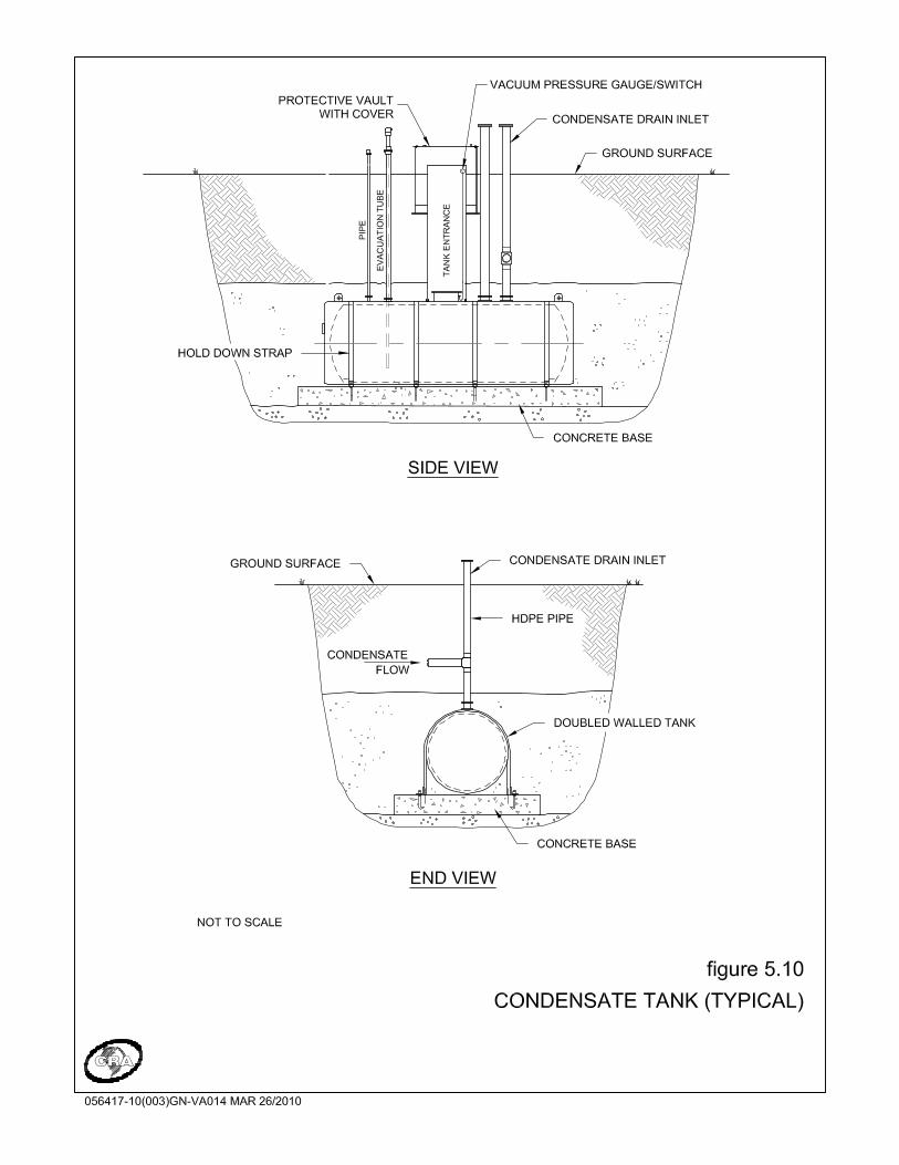
056417 (3) 96 CONESTOGA-ROVERS & ASSOCIATES
5.1.4 LEACHATE COLLECTION SYSTEM CONNECTIONS
In some situations, an opportunity is available for collection of LFG from the leachate collection system. This is usually accomplished using interconnections to that system. These connections serve to maintain a vacuum on the leachate collection piping, thereby reducing odour at the manholes and also supplementing the collection field. Each of the leachate system access points are generally equipped with a valve and monitoring port. In addition, each leachate system access point should be sealed to minimize air leakage to the LFG collection system. Often, a leachate collection system can act as a significant source of air intrusion into the waste and thus the LFG management system, potentially leading to long-term deleterious effects. Generally, the objective of drawing LFG from the leachate connection system is related to odour control, and this activity seldom by itself supports the basis of a LFG combustion process. For the purposes of this Guideline, vacuum connection to the leachate collection system will be supplemental to an active LFG collection system in the waste. It is important to balance vacuum draw on the leachate system, as there is potential for air intrusion through this system and into the LFG system, thereby introducing oxygen into the LFG flow. The potential also exists for oxygen intrusion into the leachate collection system, which can lead to biological fouling of the leachate collection system and a reduction in leachate collection and other potential impacts to the system. 5.1.5 MONITORING POINTS
Though this has been discussed earlier, it is important to note the importance of monitoring points in a LFG management system. Where the objective is to maintain a high collection efficiency, response to changes in LFG composition and flow can be facilitated by inclusion of monitoring points at key locations; generally, monitoring points are low cost and provide relevant information that can be used to balance, optimize, and troubleshoot the system. Monitoring points for flow measurement in chambers (e.g., condensate traps, isolation valve chambers) typically require confined space entry. Velocity ports may not be practical in these areas. The following basic elements should be included in any LFG management system: • A control valve to modulate the amount of vacuum applied at vertical and
horizontal extractions points to the local waste. Typically, ball and gate valves have been used for this application, but in either case it is important to provide sufficient
056417 (3) 97 CONESTOGA-ROVERS & ASSOCIATES
control over the applied vacuum. Ball valves of 50 mm (2-inch) diameter are typically a good compromise between overall pressure drop and vacuum control.
• Monitoring ports on both sides of vertical and horizontal extraction point control valves to assess the system and well-side vacuum levels and gas composition.
• Monitoring ports on both sides of subheader control valves to allow for rapid determination of problem spots in the LFG collection field. Elevated extraction plant oxygen, for example, can be isolated by identifying one or more subheaders with elevated oxygen levels and then performing a round of monitoring on the wells connected to those systems.
• Monitoring ports at condensate traps or other header locations (e.g., isolation valve chambers) where the header is exposed within a manhole in order to provide additional functional information regarding the transmission system.
• Access ports or caps at vertical wells to allow for water/leachate level determination.
• Monitoring ports on the main header at the extraction control plant to permit confirmation of continuous gas analyzer readings.
• Monitoring points for flow measurement at wells and subheader control valves to derive flow rate data that can be used as part of a diagnostic approach for troubleshooting. While velocity readings are not a primary requirement, best management practices would encourage the implementation of monitoring ports that can allow for these measurements as required.
Irrespective of the location of the monitoring port, it should be such that no confined space entry or unsafe activity is required to undertake standard monitoring. In landfills with fully or partially-buried well chambers, this is a particular concern, but one that can be mitigated by ensuring that monitoring ports are extended to and accessible at the top of the chambers. 5.2 LANDFILL GAS EXTRACTION PLANT
A number of components are related to the extraction plant as discussed in the below sections. A utilization facility will be supplemental to extraction plant components discussed in this section, as a LFG flare and the associated LFG extraction plant are required as backup to the LFG utilization equipment. As a general design standard:
056417 (3) 98 CONESTOGA-ROVERS & ASSOCIATES
Design Standard 6
Systems can be utilized when the utilization system shuts down. Although the typical uptime of a well-run utilization system is generally quite high (higher than 90 percent and potentially higher than 95 percent), some amount of downtime can be expected, and in extreme cases, may require long-term operation of the backup flare system. 5.2.1 EXTRACTION PLANT COMPONENTS
The LFG extraction plant includes the mechanical and electrical components of the LFG management system that actively collects LFG from the site. Figures 5.11 and 5.12 show a typical plant process schematic and a typical plant compound arrangement, respectively. Table 5.3 presents a summary of pertinent considerations for design of LFG extraction plants.
An active LFG collection system must include a complete LFG extraction control plant on-site with a LFG flare. If flaring will be the primary methane destruction device, an enclosed high-efficiency flare will be utilized. A candlestick flare may be utilized as the backup system to the utilization system, or may be used when there is a surplus of LFG collected (above the capacity of the utilization system). However, where a utilization system is in place and a candlestick flare is used as backup, the candlestick flare will not be the primary combustion device. This is required to ensure continuous combustion of LFG. Where a utilization system is the primary receiver of LFG, the independent backup system may include a candlestick flare, under the premise that this flare will only be used on an intermittent basis to address utilization facility downtime. For all other situations, a high-efficiency enclosed drum flare is the preferred combustion device. The only potential exception to this case is where it is impractical to obtain an enclosed drum flare, such as potentially for very small landfills.

056417 (3) 99 CONESTOGA-ROVERS & ASSOCIATES
Table 5.3: Summary of LFG Extraction Plant Design Considerations
Plant Site Centrally located with respect to landfill Provide sufficient space for future expansion Consider zoning and proximity to adequate power supply, sewers, and water supply Consider proximity to fuel users, power grid interconnections, and natural gas pipelines Minimize visual and noise impacts Consider location to not impede future landfill expansion Facility Modular plant may offer savings Enclosing equipment in buildings reduces maintenance costs, enhances security, and
reduces visual and noise impacts Buildings containing gas piping or equipment are classified as hazardous areas by
electrical code Provide buildings with interior air monitoring and alarms, and pressure release panels Enclose electrical switch-gear and controls in a separate building from gas piping and
equipment Provide space to add equipment in the future Components Valves and controls as required for safe operation in accordance with applicable codes Provide condensate pumping or storage Provide LFG flow metering and recording Provide sufficient blowers or compressors to meet capacity requirements, plus one
standby unit


056417 (3) 102 CONESTOGA-ROVERS & ASSOCIATES
In general, most systems are equipped with a centrally located control plant that also contains the flare. Depending on the size and configuration of the site, more than one collection plant may be required. These plants may serve as pressure boost stations to deliver the collected LFG to a central location. In some cases, it may also prove beneficial to have more than one flaring station. The LFG flare or some other disposal system is generally located at the LFG extraction plant. Overall system controls are usually also incorporated into the LFG extraction plant. The ideal configuration is a plant centrally located and at the lowest elevation point in the land surrounding the site. This will facilitate system operation hydraulics and the drainage of condensate. It is recognized, however, that it may not be practical to accomplish this at some sites. Engineered solutions are available for less than optimal conditions. These may involve selection of large pipe diameters, selection of larger blowers, construction of pump stations, and construction of pressure boost stations. Such measures increase the overall cost of the system. The primary components of a typical LFG extraction plant include the following: Condensate trap and condensate removal system
Piping and valves
LFG metering (quantity and quality)
LFG extraction blowers
LFG combustion devices
The piping system at the flare station may be designed to allow for independent operation of dual headers, allowing direction of the collected gas to the flares or to any future LFG utilization facility. If the LFG utilization plant is built, the collection plant and operating capacity should be maintained to act as a backup in the event of LFG utilization plant downtime or if the LFG utilization plant does not use all the recovered LFG. Note that turndown ratios of modern flares are such that these units can operate at lower flows than the maximum design capacity. In some cases, it may be possible to operate both a flare and utilization system concurrently, but the blowers for each system must be carefully balanced to do so. As an active LFG management system is required to be installed at all regulated landfills, LFG will be collected and flared and/or utilized for beneficial purposes (Refer to Sections 9(1) and 9(2) of the Regulation).

056417 (3) 103 CONESTOGA-ROVERS & ASSOCIATES
The LFG extraction plant may be enclosed within a building or left exposed to the elements. Housing the various equipment components within a building reduces noise and visual impacts of the plant. Maintenance costs may be somewhat reduced by protecting the equipment from severe weather conditions. Enclosure of LFG pipelines and conveying equipment within a building results in the creation of an area that is typically classified as a Class I, Division D, Group 2 area according to the Canadian Electrical Code classification system. This requires that all equipment within the area be rated as explosion-proof and that special precautions be taken to seal conduits entering the area. Buildings that house the LFG extraction plant are generally subject to hazards from LFG, which may migrate into the soil beneath the building or leak from piping and equipment within the building. Therefore, LFG extraction plant buildings should be equipped with electronic combustible gas detection systems with alarms; see Section 9.0 for performance requirements related to on-site health and safety. The blower building should be equipped with blow-out panels to allow pressure release in the event of an explosion within the building. A separate room should be constructed to house the electrical control panels, motor control centres (MCCs), and programmable logic controller (PLC). The plant buildings should also be equipped with foundation ventilation systems or other means of protection according to the potential hazard. An open-air steel framed shelter is also sometimes used to house extraction plant equipment such as blowers, valves, header piping, and LFG analyzers/flow meters. It is possible to include provisions for attaching temporary tarps to the shelter to permit greater protection from the elements during maintenance activities. In extremely cold environments, and where the LFG extraction equipment is backup to a utilization facility, the potential for freezing of equipment exists during prolonged downtime in this configuration. Note that while it is not expected that LFG migration to the blower shelter is a concern, underground conduit should not be permitted to avoid any potential migration of LFG. Modular or "skid-mounted" LFG extraction plants are also available. These modular systems can be configured to include all the components of a LFG extraction plant, including moisture separator, valves and piping, blowers, flare, and controls. These systems are available in a wide range of plant capacities and may offer some cost savings. While often referred to as "skid-mounted," these modular LFG extraction plants cannot be considered readily portable. Modular systems require permanent foundations,
056417 (3) 104 CONESTOGA-ROVERS & ASSOCIATES
power supply, piping connections, fenced compounds, etc. Modular components can be installed within a building. 5.2.1.1 CONDENSATE HANDLING
Condensate management is a critical component in the design of LFG collection and utilization systems. As LFG is extremely moist, it produces condensate within the LFG transmission piping. As discussed above, the transmission piping should be sloped to drain condensate towards areas where it can collect and be subsequently handled. All of the piping should be designed to prevent the accumulation of condensate within the piping, which in adverse conditions can minimize, and in some extreme cases prevent, gas flow through the transmission piping. Operationally, condensate accumulation will also reduce effective vacuum on portions of the well field, thereby reducing the yield of LFG. While there is a requirement for condensate handling prior to the combustion device, condensate removal is also undertaken in the collection field at various points. An estimate of condensate generation should be undertaken, and collection field piping sloped to allow for condensate to drain to collection points. This may necessitate multiple condensate removal points in the collection system. The below discussion is common to condensate removal in the field or at the extraction plant. A potential reason for condensate build-up within the waste discharge area is the uneven or differential settlement of the waste, which can cause a dip or low point in the piping systems that can then fill with condensate. It is for this reason that LFG collection systems should be designed with excess capacity (i.e., pipe diameter, slopes) and specific consideration in the design for identifying and addressing settlement issues. One method of estimating condensate flow is to assume that the LFG is saturated and that all the moisture condenses out of the gas. A typical condensate quantity will be in the range of 30 to 50 mL/m3 of collected LFG. Depending on the design of the LFG collection system, it may be appropriate to include an allowance for direct contribution of liquids from the site into the LFG system via horizontal collection trenches that may transmit leachate. In some cases, the transmission of leachate through horizontal collectors may be the main factor in designing liquids removal systems. To dispose of collected condensate in an environmentally sound manner, it is recommended to direct the condensate to the leachate collection and management

056417 (3) 105 CONESTOGA-ROVERS & ASSOCIATES
system. It may be possible to direct the condensate back into the waste; however, this is highly dependent on site conditions. Condensate drained from the subheader or lateral piping into the header can be handled by establishing condensate traps along the perimeter header transmission line. It is generally advisable to locate the condensate traps adjacent to existing leachate manhole structures, if available, such that accumulated condensate can be discharged either via gravity or by pumping to the leachate collection system. One particular design for condensate removal involves the use of a p-trap wherein accumulated liquids are added to an established liquid column that transmits condensate directly into a leachate control system or into a manhole that allows for pumping of this liquid to a leachate disposal system. While disposal of condensate from the manhole may occur at discrete intervals, such as through the use of automatic level controls to activate submersible pumping systems, condensate removal should occur on a continuous basis, consistent with the operation of the LFG management system. Where p-traps are used, it is important to ensure that they are able to withstand the system operation vacuum, with sufficient factor of safety to resist pressures applied as a result of system start-up and shutdown. In some instances, the use of this design approach for the p-trap is insufficient to withstand start-up vacuum, and it is possible to draw the liquid from the trap into the header system. Should this occur, an opening develops in the LFG control system and air will intrude from the condensate trap manhole into the LFG system. This represents a significant intrusion point that may cause significant upset at the LFG control plant. As such, the dimensions of the p-trap should be designed to withstand surge conditions at start-up and shutdown; use of variable frequency devices (VFDs) as part of the blower system can mitigate issues related to surge. Note that the diameter of p-trap piping should not decrease across any leg, as this may present an opportunity for accumulation of sediment and blockage of the trap. As part of best management, it is recommended that the diameter of the p-trap piping should not be less than 50 mm (2-inch) diameter. If a p-trap becomes blocked, the ability of this collection point to remove condensate will be impaired and condensate collected in the header system will accumulate in the main LFG transmission piping. This generally leads to increased pressure drops and blower exertion, and in extreme cases where the main header before the extraction plant is blocked, complete impairment of the LFG system. Unsteady pressure readings at the condensate trap may indicate the initial stages of a p-trap blockage.

056417 (3) 106 CONESTOGA-ROVERS & ASSOCIATES
Where applicable, each condensate forcemain should be equipped with a check valve to prevent the flow of leachate back to the condensate chamber. The condensate trap chambers should also be designed to allow regular maintenance of all components without requiring confined space entry procedures to be performed. In some cases, airtight collection drums are utilized in the header system to drop out liquid, under the assumption that the internal space of the drums are disconnected from the atmosphere, thereby preventing the intrusion of atmospheric air into the header system. Periodically, the liquid from the drums must be removed. Additionally, some condensate removal systems are installed on piping installed within the waste. Note that in some jurisdictions, reinfiltration of condensate back into waste is not permitted. As mentioned previously, condensate may be reintroduced into the waste for certain landfills in BC. An example would be a landfill located within relatively dry locations (e.g., the BC southern interior). Drip legs throughout the LFG collection system may be installed at such sites and condensate can be pumped back to the landfill from the condensate removal systems located at the LFG extraction plant or utilization facility. This will lead to elevated LFG generation rates and may increase the leachate produced and collected at the landfill. A qualified person must assess the advantages and potential risks associated with reintroducing condensate back into the waste by considering the landfill water balance, the leachate collection system design and operation, slope stability, the natural attenuation characteristics (if applicable), and the potential for leachate seeps. These factors must be considered when deciding if condensate should be reinfiltrated into the waste and, if so, how much condensate can safely be reinfiltrated. Once removed from the system, condensate must be disposed of in an environmentally sound manner. Condensate is suited to disposal in a leachate collection system, if available at the landfill. The chemical characteristics of condensate are highly variable from site to site; depending on its chemical characteristics, in some localities condensate may be discharged into the sanitary sewer for subsequent treatment at an off-site sewage treatment plant. Generally, a small pumping station and forcemain will be required to deliver the condensate to the sanitary sewer. If there is no nearby sanitary sewer connection or the condensate cannot be discharged to the sanitary sewer, temporary on-site storage of condensate or on-site treatment may be required. A holding chamber or underground storage tank may be used for this purpose. When full, the storage vessel may then be pumped out and the condensate delivered by truck to the sanitary sewer or an approved liquid waste treatment facility.

056417 (3) 107 CONESTOGA-ROVERS & ASSOCIATES
Photo 7: Condensate Trap Manhole
In addition to accumulated liquid water, water droplets may also require removal. Condensate knockout systems remove droplets of liquid from the flowing LFG, and are utilized to reduce the detrimental effects that the corrosive condensate may have on gas handling equipment. A simple condensate knockout system may consist of a drum-type vessel that removes only large droplets of moisture (see Figure 5.13). If downstream equipment needs dictate a more sophisticated moisture removal system, filters or demisters may be employed to provide higher removal efficiency. At most sites where low pressure centrifugal blowers are used for LFG extraction, a simple drum-type condensate knockout will likely be sufficient. At sites where higher pressure equipment is used for LFG extraction and/or utilization, the more complex, high-efficiency moisture removal system will be required. At some sites, solid particulate matter in the gas has been problematic. Fine particles of sand or grit can abrade gas-handling equipment (low or high pressure) and can plug flame arrestor cores. At sites where this proves to be a problem, in-line particulate filters may be installed in the gas piping.
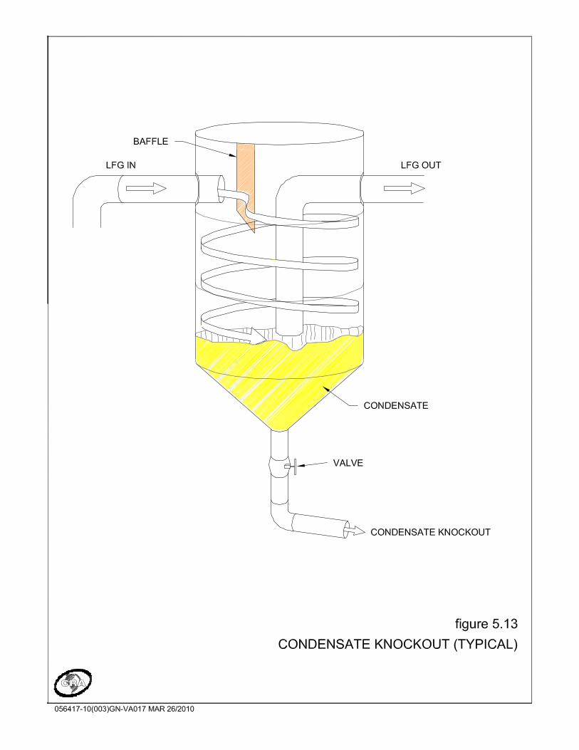

056417 (3) 109 CONESTOGA-ROVERS & ASSOCIATES
5.2.1.2 LANDFILL GAS METERING
Measurement of LFG flow rate and methane, oxygen composition, and stack temperature at the LFG extraction control plant is important from both an operational and reporting standpoint. For the purpose of this Guideline, the following design standard has been set for the LFG extraction control plant: Design Standard 7 Note that this requirement has been partially predicated on the monitoring requirements for GHG emission reduction protocols for so-called offset projects that generate carbon credits. It is expected that this information will be utilized in the annual reports required by the BC MOE regarding the status and emission reductions achieved by the LFG management system. Of further note, continuous logging of flow rate, methane, oxygen, and stack temperature allow for response to field issues that may arise. For example, sudden increases in oxygen content can indicate either a subsurface piping break or potentially a loose connection in a wellhead. These items can then be addressed through focused monitoring of the LFG collection system. Several types of equipment are able to provide continuous monitoring of the above parameters. For flow meters, it is recommended that mass-compensated flow meters be utilized, as these devices will correct for changes in LFG density resulting from differing pressure and temperature. Temperature and pressure-compensated flow meters can be utilized, as can thermal mass flow meters that also present LFG in standardized flow units. It is critical, given the current emphasis on GHG emission reduction quantification, that the conditions of flow normalization are understood. For temperature and pressure-compensated mass flow meters, for example, the standard temperature and pressure conditions define the LFG density that will be used to calculate the emissions achieved in tonnes of carbon dioxide equivalent. This is a common issue when LFG management systems undergo verification for the purpose of certifying GHG emission reductions.
LFG flow rate (in m3/hr or equivalent), methane composition (in percent by volume), oxygen content (in percent by volume), and flare stack temperature (in degrees Celsius) must be measured on a continuous basis with ongoing logging of all data on an aggregated period of not less than every five minutes.

056417 (3) 110 CONESTOGA-ROVERS & ASSOCIATES
In terms of analyzers, the industry-standard technique for methane analysis involves infrared sensors, which are similar to portable units used for field monitoring. These are relatively robust systems that present accurate measurement, although generally there is a requirement for upstream processing of the gas to make it suitable for the detector. This includes temperature modification and moisture removal, as well as particulate screening in some cases. Oxygen sensors are relatively standard and can be of a variety of types. It is important for any continuous measurement systems that are intended to log GHG emission reduction credits that testing and calibration of the systems are undertaken according to the requirements of the GHG mechanism and the requirements of the equipment manufacturer. This is a key issue in GHG verification processes. Additionally, data retention is critical; if the data record is incomplete, emission reductions are likely jeopardized. Appropriate calibration of LFG analyzers is appropriate irrespective of the requirements of a GHG mechanism. In some cases, autocalibration equipment is utilized, wherein calibration gas is present in the vicinity of the LFG analyzer and autocorrects the analyzer settings on a periodic basis. These systems are becoming more common in the international GHG market and their usage should be factored against the objectives and revenues associated with the LFG management system. Note that the placement of this equipment at the LFG extraction control plant is important. Flow meters generally require some amount of straight run of pipe upstream and downstream without any flow disturbances such as insertions, contractions/expansions, or bends; manufacturer's specifications should be consulted in order to determine specific requirements. LFG analyzers can intercept flow either on the positive or negative pressure side of the LFG blower as long as equipment is provided to modulate or draw flow from the LFG header. In colder climates, heat tracing may be required on the sample line from the header to the LFG analyzer.

056417 (3) 111 CONESTOGA-ROVERS & ASSOCIATES
Photo 8: Inside of Landfill Gas Analyzer
5.2.1.3 LFG EXTRACTION BLOWERS AND EQUIPMENT
The blower system includes all components that are used to generate and apply the vacuum to collect the LFG and supply it for its subsequent end use. A blower system should be centrally located with sufficient space for expansion, close to the end user (power grid or end user pipelines). The blower system may be enclosed in a building or it may be pad mounted as an exterior installation within a shelter. It is preferable to match blower and flare flow capacities to simplify system operations. Selection of larger blower and flare capacities may limit the ability to operate a flare at
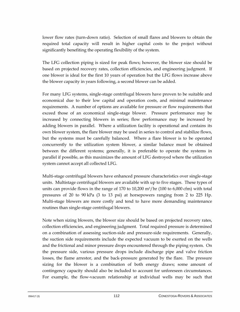
056417 (3) 112 CONESTOGA-ROVERS & ASSOCIATES
lower flow rates (turn-down ratio). Selection of small flares and blowers to obtain the required total capacity will result in higher capital costs to the project without significantly benefiting the operating flexibility of the system. The LFG collection piping is sized for peak flows; however, the blower size should be based on projected recovery rates, collection efficiencies, and engineering judgment. If one blower is ideal for the first 10 years of operation but the LFG flows increase above the blower capacity in years following, a second blower can be added. For many LFG systems, single-stage centrifugal blowers have proven to be suitable and economical due to their low capital and operation costs, and minimal maintenance requirements. A number of options are available for pressure or flow requirements that exceed those of an economical single-stage blower. Pressure performance may be increased by connecting blowers in series; flow performance may be increased by adding blowers in parallel. Where a utilization facility is operational and contains its own blower system, the flare blower may be used in series to control and stabilize flows, but the systems must be carefully balanced. Where a flare blower is to be operated concurrently to the utilization system blower, a similar balance must be obtained between the different systems; generally, it is preferable to operate the systems in parallel if possible, as this maximizes the amount of LFG destroyed where the utilization system cannot accept all collected LFG. Multi-stage centrifugal blowers have enhanced pressure characteristics over single-stage units. Multistage centrifugal blowers are available with up to five stages. These types of units can provide flows in the range of 170 to 10,200 m3/hr (100 to 6,000 cfm) with total pressures of 20 to 90 kPa (3 to 13 psi) at horsepowers ranging from 2 to 225 Hp. Multi-stage blowers are more costly and tend to have more demanding maintenance routines than single-stage centrifugal blowers. Note when sizing blowers, the blower size should be based on projected recovery rates, collection efficiencies, and engineering judgment. Total required pressure is determined on a combination of assessing suction-side and pressure-side requirements. Generally, the suction side requirements include the expected vacuum to be exerted on the wells and the frictional and minor pressure drops encountered through the piping system. On the pressure side, various pressure drops include discharge pipe and valve friction losses, the flame arrestor, and the back-pressure generated by the flare. The pressure sizing for the blower is a combination of both energy draws; some amount of contingency capacity should also be included to account for unforeseen circumstances. For example, the flow-vacuum relationship at individual wells may be such that

056417 (3) 113 CONESTOGA-ROVERS & ASSOCIATES
additional vacuum is required to draw the expected volumes of LFG. Generally, total energy requirements for LFG blowers are in the range of 50 in WC, but may be higher depending on the configuration of the LFG collection system and the nature of the control plant equipment. The blower motor should be rated explosion-proof; specific classification according to code should be undertaken to determine specific requirements. The blowers will be of spark resistant construction and all components coming in contact with the LFG will be corrosion resistant. The blower should also be equipped with shaft seals to minimize leakage of LFG out of, or air into, the blower housing. Flexible connections for both the inlet and outlet of the blower are usually provided to absorb vibrations during operation and prevent the transmission of vibrations to the plant piping. Valving on either side of the blower should be provided along with an actuated fail-safe valve to permit controlled isolation of the blower from the LFG collection system during shutdown and emergency shutdown operations (CAN/CGA, 2007). It is common and advisable as part of best management practice to equip each blower with a variable frequency drive (VFD). A VFD allows manual flow control of the blower speed to accommodate for changes in LFG available from the LFG collection field. This can be an important component of overall collection field management, as a VFD allows for rapid response to collection field issues by allowing for adjustment of the exerted vacuum and thus the received flow. Additionally, VFDs allow for more gradual start-up and application of vacuum to the well field, allowing for better management of condensate traps where p-traps are used. In some cases, where greater pressure requirements must be met, compressors may be used. Compressors are available to suit a wide range of flow requirements at pressures greater than 345 kPa (5 psi). Compressor systems are not commonly selected for LFG collection systems, but may be necessary if very long pipelines are required. Compressors are more common in LFG utilization applications where the equipment to be supplied, such as an engine, requires higher feed pressure than will a flare. Compressors are more costly than single- and multi-stage blowers and maintenance is generally more costly and time consuming than maintenance of centrifugal blowers.
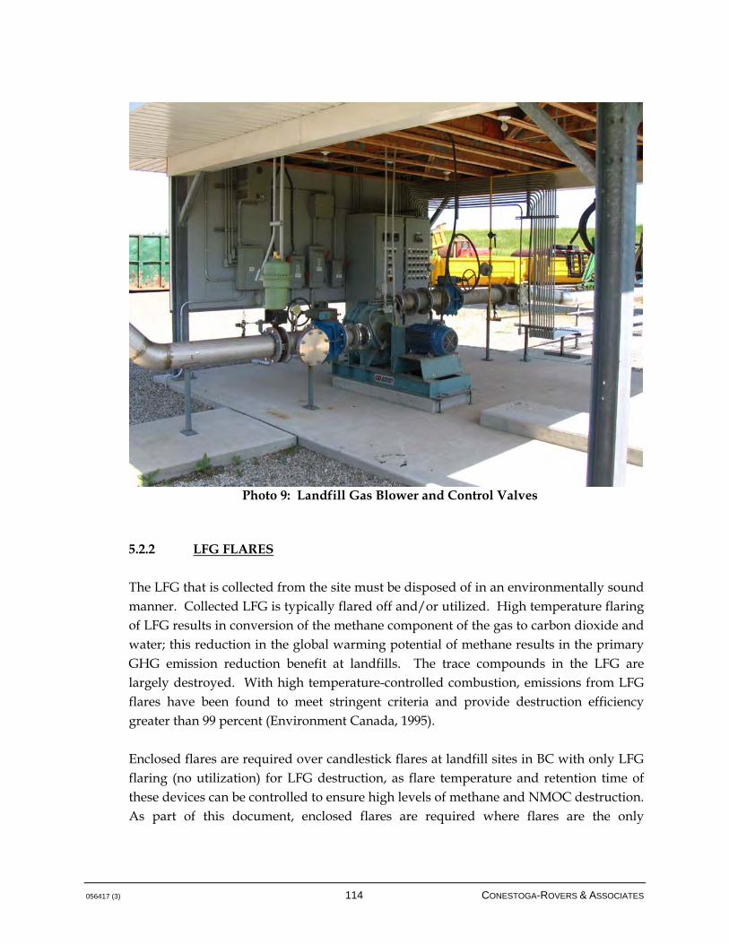
056417 (3) 114 CONESTOGA-ROVERS & ASSOCIATES
Photo 9: Landfill Gas Blower and Control Valves
5.2.2 LFG FLARES
The LFG that is collected from the site must be disposed of in an environmentally sound manner. Collected LFG is typically flared off and/or utilized. High temperature flaring of LFG results in conversion of the methane component of the gas to carbon dioxide and water; this reduction in the global warming potential of methane results in the primary GHG emission reduction benefit at landfills. The trace compounds in the LFG are largely destroyed. With high temperature-controlled combustion, emissions from LFG flares have been found to meet stringent criteria and provide destruction efficiency greater than 99 percent (Environment Canada, 1995). Enclosed flares are required over candlestick flares at landfill sites in BC with only LFG flaring (no utilization) for LFG destruction, as flare temperature and retention time of these devices can be controlled to ensure high levels of methane and NMOC destruction. As part of this document, enclosed flares are required where flares are the only
056417 (3) 115 CONESTOGA-ROVERS & ASSOCIATES
combustion device associated with the active LFG control system (see Design Standard 6, Section 5.2). Any landfill site with a LFG utilization facility will also have a LFG flare in the event that the utilization facility is down for maintenance or repair, or a surplus of LFG is collected (See Design Standard 6, Section 5.2). The use of the flare as a backup provides LFG management system reliability and allows the methane component of LFG to be destroyed on a continuous basis. There are two basic types of flares: enclosed drum devices that offer controlled combustion and high-efficiency destruction of methane and trace compounds, and candlestick flares, which have been extensively used in the past but are now being replaced by enclosed flares. LFG typically contains less than 1 percent of NMOCs and trace amounts of inorganic compounds. Some of these compounds have strong, pungent odours (i.e., hydrogen sulfide). Nearly 30 organic hazardous air pollutants have been identified in uncontrolled LFG, including benzene, toluene, ethyl benzene, and vinyl chloride. Many NMOCs identified in LFG are either known or suspected carcinogens, and have the potential to produce non-cancer health effects as well, such as adverse effects on the kidneys, liver, and central nervous system. (USEPA, 2010). Note that one of the particular advantages of candlestick flares as backup to utilization systems is the relatively large turn-down ratio, allowing the candlestick flare to operate at much less than full design capacity. This level of control may be required where the excess volumes available for combustion are small. Generally, it is recommended that flares are equipped with alarms related to oxygen content as a safety procedure. Warnings generally occur in the vicinity of 2 percent oxygen; shutdown proceeds at 4 percent by volume oxygen. The overall intent of these alarm levels is to maintain safe conditions related to flare operation, but also to ensure safe operation of the LFG collection field in terms of preventing excess oxygen intrusion to minimize the potential for landfill fires. Note that if the intrusion pathway for air into the landfill is such that oxygen is consumed via biological or other activity in the waste, a low oxygen-high nitrogen situation may present itself. In this situation, there may be an unsafe operating condition in the LFG collection field that requires attention even if oxygen levels at the flare are beneath warning levels.

056417 (3) 116 CONESTOGA-ROVERS & ASSOCIATES
5.2.2.1 CANDLESTICK FLARES
A candlestick flare typically consists of a vertical pipe with a flare nozzle, and is sometimes equipped with a wind shield (see Figure 5.14). Often, a candlestick flare is equipped with a base, allowing it to be portable at lower capacities. Candlestick flares are still common in some industries, including the oil and gas and wastewater sectors, but are generally becoming less prevalent for LFG combustion. In some jurisdictions, obtaining approvals for candlestick flares can be difficult, given that the actual emissions from these devices are difficult to quantify via measurement. Candlestick flares should meet CGA requirements, including a flame arrestor, ignition pilot, and thermal and check valves. Although they offer a low-cost method of disposing of LFG, the combustion temperature of a candle flare cannot be readily controlled, and the destruction efficiency and emissions from these units may be of concern. Of further note, most of the international and domestic GHG protocols for GHG credits from LFG projects require significant discounts with respect to destruction efficiency for candlestick flares. LFG protocols can discount destruction efficiencies from candlestick flares of up to 75 percent in some cases; at the Clean Development Mechanism level, the rates discount is 50 percent. From a purely economical standpoint, where GHG combustion credits are available and the price per tonne of carbon dioxide equivalent is even nominal, implementation of an enclosed drum flare to replace a candlestick flare can be readily justified (CAN/CGA, 2007). As stated in Design Standard 6 (Section 5.2), a candlestick flare should only be in operation if one of the following scenarios occurs: The utilization facility is temporarily down due to maintenance or repair
There is a surplus of LFG that exceeds the capacity of the utilization system. The candlestick flare may thus be used during the staging of the utilization facility concurrently with the utilization technology, but must not be the primary combustion device at the site.
5.2.2.2 ENCLOSED FLARES
Enclosed flares consist primarily of a vertical stack with burner nozzles and combustion air inlets located at the base (see Figure 5.15). The shell of the stack is typically steel and is lined with refractory insulating material. The flare is designed to achieve a specified combustion temperature and retain exhaust gases at that temperature for a specified
056417 (3) 117 CONESTOGA-ROVERS & ASSOCIATES
time. This ensures that a minimum degree of destruction of contaminants is achieved. Typical values for temperature and retention time are in the range of 760 to 1,000 degrees Celsius for a period of 0.5 to 1.0 seconds. There is ample evidence in the literature to support the contention that these combustion conditions are suitable to achieve high destruction efficiencies of methane and trace compounds; emissions tests performed at Metro Toronto's Keele Valley and Brock West Landfill sites and at numerous American sites (Mostardi et al., 1991) have demonstrated effective control of emissions from enclosed flares that meet the temperature specifications noted above.
Photo 10: Skid-Mounted Landfill Gas Flare Package
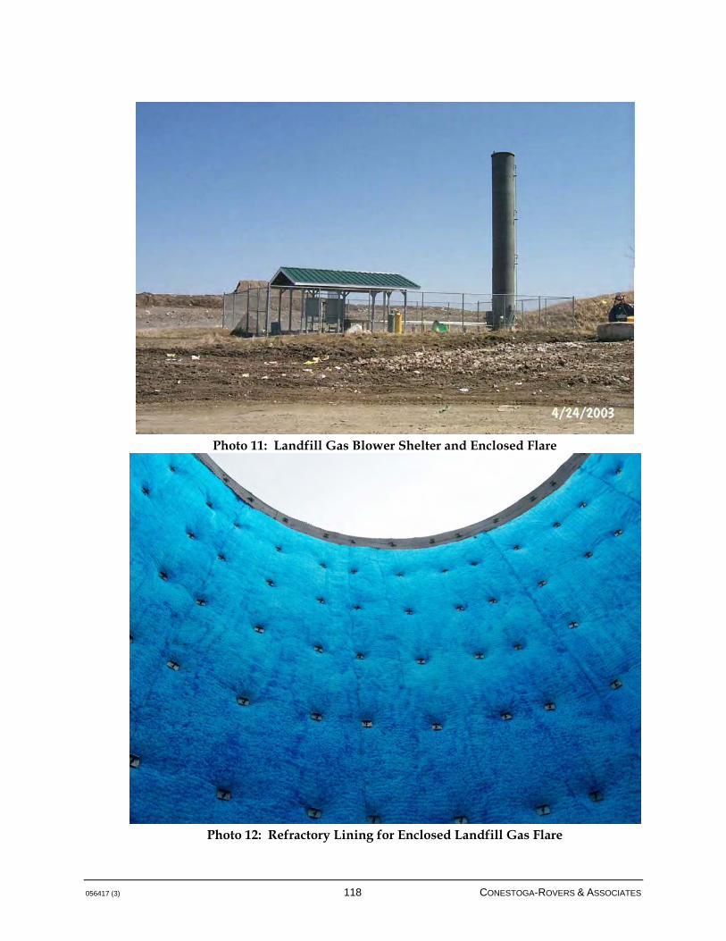
056417 (3) 118 CONESTOGA-ROVERS & ASSOCIATES
Photo 11: Landfill Gas Blower Shelter and Enclosed Flare
Photo 12: Refractory Lining for Enclosed Landfill Gas Flare

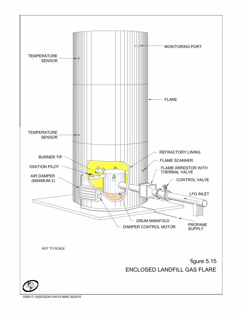

056417 (3) 121 CONESTOGA-ROVERS & ASSOCIATES
Design Standard 8 A multi orifice burner and burner chamber are enclosed in the stack, which contains refractory insulation; no visible flame should be evident for this type of combustion device from the top of the stack. Enclosed LFG flares should be equipped with the following features to ensure safe operation (CAN/CGA, 2007): Flame arrestor
Electronic ignition system
Flame sensors/scanners
Automated modulation and shut-off valves
Temperature sensors/thermocouples
Electronic interlocks to shut the system down under fault conditions
Combustion temperatures are controlled by a system of automatically and manually controlled air inlet dampers and thermocouples located in the stack; these devices work to modulate the combustion air-inlet dampers to control the amount of air required to support LFG combustion. As an exit gas temperature signal is sent to the PLC and data logging system, the inlet dampers can adjust the amount of outside air to the flare interior for combustion oxygen. Immediately downstream of the flare control valve, a flame arrestor and thermal valve combination should be installed. This is a safety device that will be used to prevent rearward propagation of the flame from the flare into the plant piping. The flame arrestor body contains a bank of stainless steel sheets laid one on top of the other, which effectively dissipates the heat should the flame burn back into the piping. The thermal valve contains a fusible link that melts in the event of a flame burnback, shutting the valve. The fusible link can be replaced if required. The flare will typically be equipped with an automatic propane pilot system fueled by on-site propane tanks. The automatic propane pilot is controlled by the PLC in the main
An enclosed flare must be designed to have a minimum retention time of 0.5 seconds and a minimum flare temperature of 875 degrees Celsius. These values are consistent with general flare design in the LFG field.
056417 (3) 122 CONESTOGA-ROVERS & ASSOCIATES
control panel. On receiving an ignition signal, the PLC activates the propane solenoid valve to open and activate the igniter that provides a spark to ignite the propane supply. The length of time the pilot is in operation depends on the mode of operation and the PLC programming. The flare should also be equipped with a purge blower as a safety feature that is used during the start cycle to purge trace LFG from the flare prior to ignition. In terms of the actual process, the following provides a general description of flare operation, which is achieved through the use of a PLC. Generally, flare start-up commences with the purge blower purging trace LFG from the flare stack prior to ignition. An automatic propane pilot system then ignites the propane supply, while LFG starts flowing toward the flare. Once a stable flame presence has been confirmed, the propane pilot igniter will shut down and the flare will operate on LFG. Flame temperature will be controlled by thermocouples located in the flare stack and by the inlet air dampers. The thermocouples monitor flare temperatures and signal the PLC when adjustments to the automatic inlet damper(s) are required to maintain proper combustion and gas temperatures. Additional flare system appurtenances will include a propane ignition system, flame scanner to prove the flame, automated controls, thermocouples, motorized air inlet dampers, flash back flame arrester, and thermal valve. The flare system is also typically equipped with a data logging system to record operational data and permit notification of the plant operator of any shutdown or alarm conditions. Generally, these systems are setup to be fully automated, thus only requiring manned attendance for general surveillance, monitoring, and maintenance. Note that enclosed drum flares are generally considered more favourable for the generation of emission reduction credits. While the destruction efficiency attributed to candlestick flares is variable across different greenhouse gas methodologies, enclosed drum flares almost uniformly are considered to have higher destruction efficiencies. 5.2.3 PROCESS CONTROL SYSTEMS
Systems for controlling the operation of the overall LFG system can be highly automated or primarily manual. At a minimum, basic functions to ensure the safe and proper operation of the system should be automated. These include:

056417 (3) 123 CONESTOGA-ROVERS & ASSOCIATES
Automatic flare temperature controls
Automatic pilot ignition confirmation interlocked with blower operation
Flare and blower operation interlocks
Main flare confirmation interlocked with blower operation
High-temperature shutdown
Automated fail-safe valve to isolate the plant piping on power outage
These process controls may be implemented using electronic relays, PLCs, or computer-based supervisory control and data acquisition systems (SCADAs). Any of these systems can adequately perform the control functions necessary for operating a LFG collection and flaring system. PLC- and SCADA-based systems are somewhat more flexible for customizing automatic controls and automated recording of data. These features can prove useful if LFG utilization is under consideration. The primary function of the control system is to ensure that the various system components are operated in a safe and efficient manner, and to shut the system down and activate alarms under fault conditions. The degree to which operation and data recording functions are automated is a matter of owner or operator preference. Security and safety systems that should be included in the plant design include: Interior ambient air monitoring for combustible gas interlocked to the ventilation
system
Heat and flame detection
Building security The plant should be equipped with warning lights and audio alarms activated by the above. It is recommended to install either a telephone service and auto-dialer or an automatic radio transmitter unit in the plant. This will provide remote notification of fault conditions or alarms to a staffed location on a 24-hour basis. Non-critical alarms should result from the following events: LFG analyzer warning - high oxygen (oxygen concentration greater than 2 percent
by volume)
LFG analyzer warning - low methane (methane less than 35 percent by volume)
056417 (3) 124 CONESTOGA-ROVERS & ASSOCIATES
Low propane supply pressure
Flare temperature alarm (low)
The occurrence of a non-critical alarm and the cause should be displayed on a control panel. The occurrence should be logged by the datalogger as a non-critical alarm, and a message should be sent to the appropriate personnel by an autodialer. Critical alarms are defined as events or conditions that require that the LFG management system be shut down. Critical alarms should result in a signal being sent to the control system (PLC, SCADA, etc.). Critical alarms can result from any one or more of the following events: High-high oxygen alarm (oxygen concentration greater than 4 percent by volume)
Low-low methane alarm (methane concentration less than 30 percent by volume)
Flame fault (no flame detected by main flame thermocouple)
Blower fault
Blower inlet bearing temperature (100C)
Blower outlet bearing temperature (100C)
Main power loss
Emergency stop
Safety valve fault
Condensate trap chamber high-high level alarm
056417 (3) 125 CONESTOGA-ROVERS & ASSOCIATES
6.0 MANAGEMENT SYSTEM COSTS
The relative costs of installing a LFG management system to collect and transport LFG to a facility can vary substantively based on site-specific conditions and the applicable design basis. A number of performance standards for design have been given in this Guideline, and these have been taken into context when providing the below generalized cost basis. The costs to install a LFG management system can vary dramatically as a function of: Quantity of waste in the landfill
Landfill dimensions
LFG generation potential
Cost of petroleum and associated products
Local costs for materials such as aggregate, pipe, and bentonite
Availability and costs for suitable construction contractors
Proximity to material manufacturing facilities
Nature of the design
The specific characteristics of a landfill site will have many direct implications for the design options and related costs of LFG management system. As such, it is highly recommended that these costs be reviewed carefully on a project-specific basis; these are guideline costs only and will certainly exhibit change over time. The costs associated with installing LFG management system components are presented in Table 6.1. A range of costs associated with installing LFG management systems based on the size of the landfill is presented in Table 6.2.
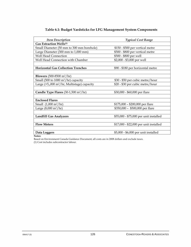
056417 (3) 126 CONESTOGA-ROVERS & ASSOCIATES
Table 6.1: Budget Yardsticks for LFG Management System Components
Item Description Typical Cost Range Gas Extraction Wells(1) Small Diameter (50 mm to 300 mm borehole) $150 - $500 per vertical metre Large Diameter (300 mm to 1,000 mm) $500 - $800 per vertical metre Well Head Connection $500 - $800 per well Well Head Connection with Chamber $2,000 - $3,000 per well Horizontal Gas Collection Trenches $90 - $180 per horizontal metre Blowers (500-8500 m3/hr) Small (500 to 1000 m3/hr) capacity $30 - $50 per cubic metre/hour Large (>5,,000 m3/hr, Multistage) capacity $20 - $30 per cubic metre/hour Candle Type Flares (30-1,500 m3/hr) $30,000 - $60,000 per flare Enclosed Flares Small (1,000 m3/hr) $175,000 – $200,000 per flare Large (8,000 m3/hr) $350,000 – $500,000 per flare Landfill Gas Analyzers $55,000 - $75,000 per unit installed Flow Meters $17,000 - $22,000 per unit installed Data Loggers $5,000 - $6,000 per unit installed
Notes: Based on Environment Canada Guidance Document; all costs are in 2008 dollars and exclude taxes. (1) Cost includes subcontractor labour.
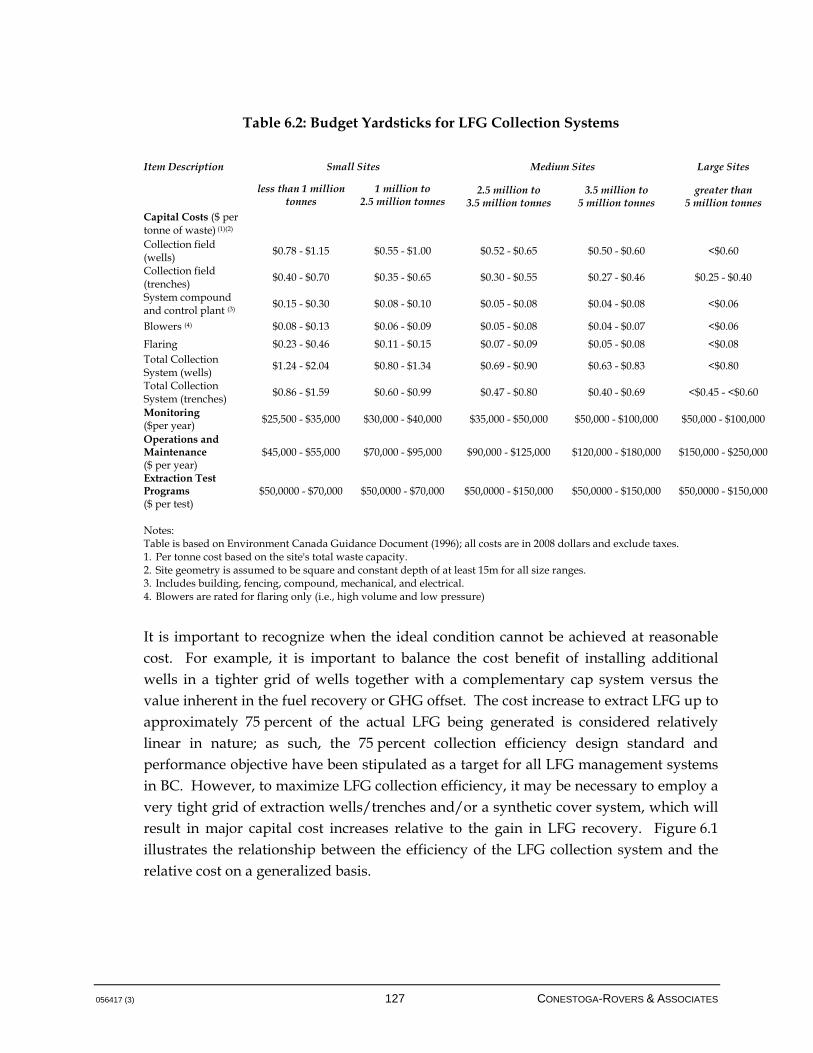
056417 (3) 127 CONESTOGA-ROVERS & ASSOCIATES
Table 6.2: Budget Yardsticks for LFG Collection Systems Item Description Small Sites Medium Sites Large Sites
less than 1 million tonnes
1 million to 2.5 million tonnes
2.5 million to 3.5 million tonnes
3.5 million to 5 million tonnes
greater than 5 million tonnes
Capital Costs ($ per tonne of waste) (1)(2)
Collection field (wells)
$0.78 - $1.15 $0.55 - $1.00 $0.52 - $0.65 $0.50 - $0.60 <$0.60
Collection field (trenches)
$0.40 - $0.70 $0.35 - $0.65 $0.30 - $0.55 $0.27 - $0.46 $0.25 - $0.40
System compound and control plant (3)
$0.15 - $0.30 $0.08 - $0.10 $0.05 - $0.08 $0.04 - $0.08 <$0.06
Blowers (4) $0.08 - $0.13 $0.06 - $0.09 $0.05 - $0.08 $0.04 - $0.07 <$0.06
Flaring $0.23 - $0.46 $0.11 - $0.15 $0.07 - $0.09 $0.05 - $0.08 <$0.08 Total Collection System (wells)
$1.24 - $2.04 $0.80 - $1.34 $0.69 - $0.90 $0.63 - $0.83 <$0.80
Total Collection System (trenches)
$0.86 - $1.59 $0.60 - $0.99 $0.47 - $0.80 $0.40 - $0.69 <$0.45 - <$0.60
Monitoring ($per year) $25,500 - $35,000 $30,000 - $40,000 $35,000 - $50,000 $50,000 - $100,000 $50,000 - $100,000
Operations and Maintenance ($ per year)
$45,000 - $55,000 $70,000 - $95,000 $90,000 - $125,000 $120,000 - $180,000 $150,000 - $250,000
Extraction Test Programs ($ per test)
$50,0000 - $70,000 $50,0000 - $70,000 $50,0000 - $150,000 $50,0000 - $150,000 $50,0000 - $150,000
Notes: Table is based on Environment Canada Guidance Document (1996); all costs are in 2008 dollars and exclude taxes. 1. Per tonne cost based on the site's total waste capacity. 2. Site geometry is assumed to be square and constant depth of at least 15m for all size ranges. 3. Includes building, fencing, compound, mechanical, and electrical. 4. Blowers are rated for flaring only (i.e., high volume and low pressure)
It is important to recognize when the ideal condition cannot be achieved at reasonable cost. For example, it is important to balance the cost benefit of installing additional wells in a tighter grid of wells together with a complementary cap system versus the value inherent in the fuel recovery or GHG offset. The cost increase to extract LFG up to approximately 75 percent of the actual LFG being generated is considered relatively linear in nature; as such, the 75 percent collection efficiency design standard and performance objective have been stipulated as a target for all LFG management systems in BC. However, to maximize LFG collection efficiency, it may be necessary to employ a very tight grid of extraction wells/trenches and/or a synthetic cover system, which will result in major capital cost increases relative to the gain in LFG recovery. Figure 6.1 illustrates the relationship between the efficiency of the LFG collection system and the relative cost on a generalized basis.
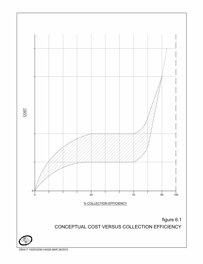

056417 (3) 129 CONESTOGA-ROVERS & ASSOCIATES
7.0 BEST MANAGEMENT OPERATIONAL PRACTICES
The design of LFG management systems has been discussed in this Guideline, and a number of standards and practices at the design level can be utilized to yield high performance systems. However, it should be specifically noted that operations are a critical parameter as it relates to the success of a system, and even a well-designed system can underperform if operations are not undertaken with specific objectives in mind. Lack of attention to the operational aspects of LFG management can lead to the following: • Inadequate LFG supply to a utilization system and the associated effects on
utilization system economics
• Diminished revenues from GHG emission reductions against forecasted yields
• Regulatory issues related to underperformance against stated performance standards
• Potential health and safety hazards to site employees and/or contractors
• Potential damage to the landfill and landfill systems including fires
The following subsections provide guidance and performance standards for LFG management system operations in the collection field and at the extraction control plant. It is recognized that operations are often a function of the skill, experience, and availability/time of the operator, and that education and training are key components of any management approach related to LFG and other landfill systems. 7.1 LFG COLLECTION FIELD
The first and most important component of successful operations is the management of the LFG collection field. This is an area that sometimes receives less attention than is required, often resulting in maintenance and performance issues. 7.1.1 COLLECTION FIELD MONITORING AND ADJUSTMENTS
Routine and scheduled monitoring and adjustment of the LFG collection field is required to optimize the effectiveness of the collection system in response to varying LFG generation rates; this activity is generally called well field balancing (Refer to Section 7.1.1.2). A well designed, constructed, and operated LFG recovery system can
056417 (3) 130 CONESTOGA-ROVERS & ASSOCIATES
collect 75 percent or more of the LFG at a landfill site. It is important for a collection system to be operated to match the site's changing LFG generation potential without over or under-drawing on the collection field. In addition to the changing LFG generation rate over the life of the landfill, the effective LFG generation rate also varies somewhat over the short term as a function of factors such as meteorological conditions, differential settlement, equipment efficiencies, and cover system conditions. The LFG collection field must be routinely monitored and adjusted to optimize the effectiveness of the collection system. The adjustment of valve settings to reduce or increase LFG flows from low or high generation areas of the landfill is required to maximize LFG collection without overdrawing from those areas of the site that may be susceptible to air intrusion. It should be noted that collection field adjustments must be made based upon a review of historic well or trench performance considered within the context of the overall field operation. Even relatively minor changes to a particular collection point will influence flow and vacuum at other locations within the collection system. A certain amount of judgment gained from site-specific experience is required when making adjustments to the collection field. If combustible gas readings at a specific well or trench are found to be substantially below the plant gas concentration, then the flow from that well or trench should be reduced. Wholescale changes in the valve position (i.e., going from fully open to fully closed) are often counter-productive, as a given well may demonstrate high oxygen/low methane at full vacuum exertion, but reasonable gas quality at some reduced level; this reflects the purpose of well control valves. Smaller changes in valve position are more conducive to effective operations, and are most useful when the history of a well relative to LFG quality and valve position are recorded and utilized to guide future balancing activities. 7.1.1.1 AIR INTRUSION AND PRINCIPLES OF BALANCING
One principle that is often misunderstood or ignored, even by those working in the LFG industry, is that the operating basis for an individual well or trench must be based solely on LFG quality at that individual well or trench. Operating a well or trench on the basis of target recovery rates or expected performance yields is counter-productive; usually, oxygen content is the dominant parameter when assessing well performance and the need for valve adjustments.

056417 (3) 131 CONESTOGA-ROVERS & ASSOCIATES
Air intrusion into the landfill must be minimized since it has a negative impact on the natural decomposition of waste and can lead to landfill fires. Introduction of ambient air into the waste mass, with its 21 percent oxygen content, can have a counterproductive effect on the natural decomposition process. At the advanced stages of methanogenic decomposition, the microbes that carry out this process survive and thrive in an oxygen-free (anaerobic) environment. Introduction of oxygen into this process will kill the anaerobic microbes, forcing the process to become aerobic. This may result in a reduction in methane generation with an associated decline in potential energy recovery, greatly increased rates of differential settlement, high subsurface temperatures, and increased odour problems. In some cases, this can lead to landfill fires. Excess vacuum that promotes air intrusion can lead to the aforementioned conditions; high vacuum that does not promote air intrusion may be appropriate in some situations. Intrusion generally manifests itself as oxygen at the wells, although it should be noted that oxygen may also be the result of leaks in the wellhead infrastructure; while this is a negative condition that must be corrected, there is no potential for waste-related impact that results from leaks in surface equipment. Earlier in this Guideline, it was recommended that two monitoring ports be attached to every well, as far apart as practically possible. This arrangement allows for an assessment of the upstream and downstream LFG quality; if the downstream gas quality shows significant deterioration (higher oxygen, lower methane) compared to the upstream point, the wellhead equipment almost certainly has a leak. Generally, this condition is easily repaired. If both monitoring ports exhibit the same poor gas quality, the leak may be in the subsurface and more difficult to address. When excess vacuum is applied on wells such that intrusion occurs, the effective radius of influence around wells diminishes as the high vacuum is addressed by short-circuiting air from the atmosphere rather than drawing from the waste mass. This will lead to potential inefficiencies in the system extraction performance via reduced LFG draw to the extraction control plant. Where the response to this condition is to increase the vacuum on the collection field, intrusion may increase yet further, LFG flows and methane composition may decrease, and oxygen content may increase such that at some point, continued operation of the LFG management system may be impaired and damage may have been done to the waste and/or collection system. Conversely, inadequate vacuum application on wells can also lead to system inefficiencies. Each well has a specific LFG flow-vacuum relationship, and underexploiting this relationship can reduce overall LFG capture volumes. Generally,
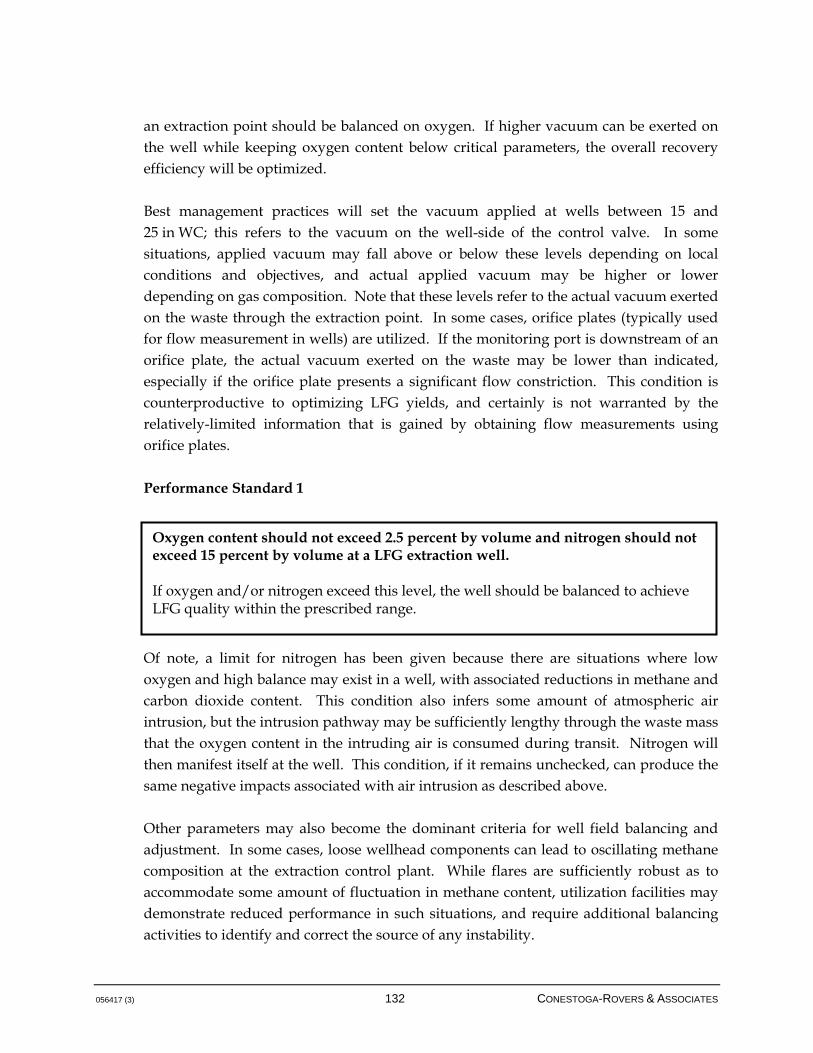
056417 (3) 132 CONESTOGA-ROVERS & ASSOCIATES
an extraction point should be balanced on oxygen. If higher vacuum can be exerted on the well while keeping oxygen content below critical parameters, the overall recovery efficiency will be optimized. Best management practices will set the vacuum applied at wells between 15 and 25 in WC; this refers to the vacuum on the well-side of the control valve. In some situations, applied vacuum may fall above or below these levels depending on local conditions and objectives, and actual applied vacuum may be higher or lower depending on gas composition. Note that these levels refer to the actual vacuum exerted on the waste through the extraction point. In some cases, orifice plates (typically used for flow measurement in wells) are utilized. If the monitoring port is downstream of an orifice plate, the actual vacuum exerted on the waste may be lower than indicated, especially if the orifice plate presents a significant flow constriction. This condition is counterproductive to optimizing LFG yields, and certainly is not warranted by the relatively-limited information that is gained by obtaining flow measurements using orifice plates. Performance Standard 1 Of note, a limit for nitrogen has been given because there are situations where low oxygen and high balance may exist in a well, with associated reductions in methane and carbon dioxide content. This condition also infers some amount of atmospheric air intrusion, but the intrusion pathway may be sufficiently lengthy through the waste mass that the oxygen content in the intruding air is consumed during transit. Nitrogen will then manifest itself at the well. This condition, if it remains unchecked, can produce the same negative impacts associated with air intrusion as described above. Other parameters may also become the dominant criteria for well field balancing and adjustment. In some cases, loose wellhead components can lead to oscillating methane composition at the extraction control plant. While flares are sufficiently robust as to accommodate some amount of fluctuation in methane content, utilization facilities may demonstrate reduced performance in such situations, and require additional balancing activities to identify and correct the source of any instability.
Oxygen content should not exceed 2.5 percent by volume and nitrogen should not exceed 15 percent by volume at a LFG extraction well. If oxygen and/or nitrogen exceed this level, the well should be balanced to achieve LFG quality within the prescribed range.
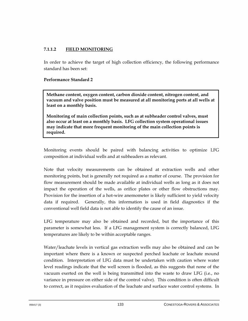
056417 (3) 133 CONESTOGA-ROVERS & ASSOCIATES
7.1.1.2 FIELD MONITORING
In order to achieve the target of high collection efficiency, the following performance standard has been set: Performance Standard 2
Monitoring events should be paired with balancing activities to optimize LFG composition at individual wells and at subheaders as relevant. Note that velocity measurements can be obtained at extraction wells and other monitoring points, but is generally not required as a matter of course. The provision for flow measurement should be made available at individual wells as long as it does not impact the operation of the wells, as orifice plates or other flow obstructions may. Provision for the insertion of a hot-wire anemometer is likely sufficient to yield velocity data if required. Generally, this information is used in field diagnostics if the conventional well field data is not able to identify the cause of an issue. LFG temperature may also be obtained and recorded, but the importance of this parameter is somewhat less. If a LFG management system is correctly balanced, LFG temperatures are likely to be within acceptable ranges. Water/leachate levels in vertical gas extraction wells may also be obtained and can be important where there is a known or suspected perched leachate or leachate mound condition. Interpretation of LFG data must be undertaken with caution where water level readings indicate that the well screen is flooded, as this suggests that none of the vacuum exerted on the well is being transmitted into the waste to draw LFG (i.e., no variance in pressure on either side of the control valve). This condition is often difficult to correct, as it requires evaluation of the leachate and surface water control systems. In
Methane content, oxygen content, carbon dioxide content, nitrogen content, and vacuum and valve position must be measured at all monitoring ports at all wells at least on a monthly basis. Monitoring of main collection points, such as at subheader control valves, must also occur at least on a monthly basis. LFG collection system operational issues may indicate that more frequent monitoring of the main collection points is required.

056417 (3) 134 CONESTOGA-ROVERS & ASSOCIATES
some cases, inserting pumps into LFG extraction wells can reduce liquid levels, but if liquid is associated with a leachate mound, it is unlikely that single pumps will influence the liquid profile. Also, some cost implications are associated with the pumps, controls, discharge of liquid, electrical requirements, pneumatic air lines, etc. required with this approach. Oxygen measurements, according to the performance standards set in this Guideline, will occur at the LFG extraction control plant on a continuous basis. An additional performance standard has been applied for oxygen: Performance Standard 3 The above performance standard is not meant to be restrictive. In some cases, especially where a utilization system is in place, it may be necessary to monitor and balance on a much more frequent basis, particularly if the LFG management system is large. Daily monitoring and balancing is not uncommon at large landfills. Additionally, LFG quality and flow can be subject to a number of meteorological conditions, one of which is atmospheric pressure. It has been observed that rapid changes in atmospheric pressure can affect LFG composition and flow. Typically, flaring systems can respond to this through modifying blower speed. For utilization systems, however, monitoring and balancing may need to respond to changes in atmospheric pressure, or even anticipate such changes by providing adjustments to well field valve settings before the pressure front arrives. There are a number of additional reasons for monitoring and balancing on a more frequent basis, and thus the performance standard for monitoring frequency should be seen as a minimum requirement. Monitoring at each collection point should begin with the measurement of vacuum pressure. A portable gas meter is then used to measure methane, carbon dioxide, oxygen, and nitrogen composition. As good monitoring practice, combustible gas readings should not be taken until after the pressure measurements, due to the possibility of interference with pressures by the action of extracting the gas sample. If
If the LFG analyzer detects high oxygen concentrations (greater than 2 percent by volume), a round of field monitoring and balancing must be initiated as soon as practically possible. If there is rapid increase in oxygen content, this implies that there is a potential break in the subsurface piping system or an issue at a wellhead, and this should be responded to immediately.

056417 (3) 135 CONESTOGA-ROVERS & ASSOCIATES
required, water/leachate levels should be taken after all gas measurements are completed, as this monitoring may require opening the LFG extraction well cap. Table 7.1 presents a simple diagnosis tool to highlight some common problems in the operation of the LFG collection and utilization facilities and their probable solutions.
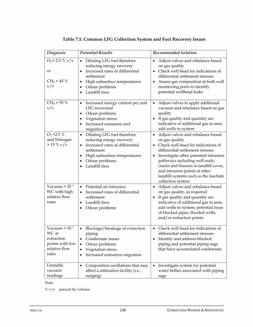
056417 (3) 136 CONESTOGA-ROVERS & ASSOCIATES
Table 7.1: Common LFG Collection System and Fuel Recovery Issues
Diagnosis Potential Results Recommended Solution
O2 > 2.5 % v/v or CH4 < 45 % v/v
Diluting LFG fuel therefore reducing energy recovery
Increased rates of differential settlement
High subsurface temperatures Odour problems Landfill fires
Adjust valves and rebalance based on gas quality
Check well head for indications of differential settlement stresses
Assess gas composition at both well monitoring ports to identify potential wellhead leaks
CH4 > 55 % v/v
Increased energy content per unit LFG recovered
Odour problems Vegetation stress Increased emissions and
migration
Adjust valves to apply additional vacuum and rebalance based on gas quality
If gas quality and quantity are indicative of additional gas in area, add wells to system
O2 <2.5 % and Nitrogen > 15 % v/v
Diluting LFG fuel therefore reducing energy recovery
Increased rates of differential settlement
High subsurface temperatures Odour problems Landfill fires
Adjust valves and rebalance based on gas quality
Check well head for indications of differential settlement stresses
Investigate other potential intrusion pathways including well seals, cracks and fissures in landfill cover, and intrusion points at other landfill systems such as the leachate collection system
Vacuum > 25 " WC with high relative flow rates
Potential air intrusion Increased rates of differential
settlement Landfill fires Odour problems
Adjust valves and rebalance based on gas quality, as required
If gas quality and quantity are indicative of additional gas in area, add wells to system; potential issue of blocked pipes, flooded wells, and/or extraction points
Vacuum < 10 " WC at extraction points with low relative flow rates
Blockage/breakage of extraction piping
Condensate issues Odour problems Vegetation stress Increased emissions migration
Check well head for indications of differential settlement stresses
Identify and address blocked piping and potential piping sags that have accumulated condensate
Unstable vacuum readings
Composition oscillations that may affect a utilization facility (i.e., surging)
Investigate system for potential water bellies associated with piping sags
Note:
% v/v percent by volume
056417 (3) 137 CONESTOGA-ROVERS & ASSOCIATES
7.1.2 COLLECTION FIELD MONITORING EQUIPMENT
A number of pieces of analytical equipment are required to carry out monitoring of the LFG collection field, including the following items: • Digital manometer
• Portable LFG analyzer
• Ancillary equipment
• Portable health and safety air monitor (i.e., 4-gas meter)
The following briefly outlines the functions of the analytical and safety equipment listed above. Of the listed items, the digital manometer and portable LFG analyzer are the most important items. 7.1.2.1 DIGITAL MANOMETER
The digital manometer is used to measure both static and differential pressures of the system at the extraction points. The manometer should measure pressure/vacuum in the range of from 0.0 to 40.0 in WC pressure or vacuum with a measurement accuracy of ±0.1. For finer adjustments to the LFG collection system, a manometer with a range of 20.0 in WC may be required. Static pressure is measured relative to atmospheric pressure by connecting the positive (+) tubing lead from the manometer to the monitoring port being sampled. The pressure should only be recorded once the monitoring port ball valve is opened and pressure equilibrium is attained. Any fluctuating/pulsating pressures should also be noted, as this could indicate water accumulation in the well/trench, lateral, or subheader system. The digital manometer should be the first piece of equipment used at any monitoring port. 7.1.2.2 PORTABLE LFG ANALYZER
The portable LFG analyzer permits field measurement of combustible gas (methane), carbon dioxide, oxygen, and nitrogen concentrations in the LFG, where the first three
056417 (3) 138 CONESTOGA-ROVERS & ASSOCIATES
gases are measured and the last is calculated. The standard equipment used in the field incorporates an infrared detector for methane measurement, which has proven accurate and reliable; however, even this robust measurement technique can be prone to variations according to environmental conditions such as barometric pressure, temperature, and moisture. The oxygen sensor, if based on electrochemical principles, is generally the slowest to stabilize. The portable LFG analyzer is operated by connecting the meter's tubing to the monitoring port being sampled and opening the monitoring port valve. Sampling is continued until sufficient volume has been purged through the sample lines to ensure that a representative sample has been evacuated through the instrument. A reading may be taken when a stable concentration is indicated on the display. The tubing should be observed for any water as this will damage the analyzer. Filters are provided to prevent exposure of the internal instrument parts to water, which can severely damage the instrument. Spare filters and tubing should always be present when undertaking monitoring. While some portable LFG analyzers are able to determine vacuum/pressure, the use of digital manometers is still encouraged. Shop and field calibration are crucial elements to the use of this equipment. Quality control/quality assurance plans for the equipment maintenance and calibration should be recorded and applied as required. Generally, shop calibration is required for units of this nature on a schedule prescribed by the manufacturer, but which is generally at least once per year. The portable LFG analyzer should be used after the vacuum/pressure readings have been obtained. Note that it is not appropriate to utilize portable health and safety gas meters for the measurement of LFG concentrations as it pertains to monitoring; portable safety meters often provide readouts outside of the typical methane concentrations observed in LFG, and are not intended for long-term exposure to high concentrations. Also note that photoionization detectors (PIDs) are not appropriate for monitoring of LFG, as methane is not within the ionization frequency of these detectors; additionally, PIDs are highly sensitive to moisture, which is present in substantial quantity in LFG.
056417 (3) 139 CONESTOGA-ROVERS & ASSOCIATES
7.1.2.3 ANCILLARY EQUIPMENT
As noted, velocity measurement is of secondary importance when monitoring and balancing a LFG well field. In-flow measurement devices include pitot tubes and orifice plates, but both are prone to degraded performance with time during continuous exposure to LFG flow. A hot wire anemometer device is relatively accurate and can measure both flow velocity and temperature as required, provided there are sufficient and accessible monitoring points at the wells and in the piping system. A water level meter is a standard piece of equipment for measurement of liquid levels in vertical extraction wells. Interpretation of water levels is greatly facilitated if the construction details of the wells are available during the monitoring event to determine the available well screen. Use of this type of equipment should only be undertaken after vacuum/pressure and LFG composition readings have been taken and logged. 7.1.2.4 PORTABLE AIR MONITOR
The portable air monitor (gas detector) is required to verify the safety of the atmosphere in any confined space prior to entry. Confined space entry is not and should not be normally required to complete a round of collection system monitoring; however, should any entry into a condensate trap or other confined space become necessary, confined space entry procedures must be followed. It should be noted that the air monitor is a personal safety device and is not recommended for analytical purposes. Direct sampling of LFG may damage the monitor; however, its use during routine monitoring events is recommended for personal health and safety around extraction points and chambers. 7.1.3 COLLECTION FIELD REPORTING
A record of all monitoring data should be kept for maintaining a history of field performance for optimization and troubleshooting purposes. The LFG collection field monitoring records for each LFG monitoring point should include the following data:

056417 (3) 140 CONESTOGA-ROVERS & ASSOCIATES
• Time of sampling event
• Initial valve position
• Static vacuum pressure
• Methane concentration
• Carbon dioxide concentration
• Oxygen concentration
• Balance concentration
• Adjusted valve position
• LFG flow rate, as applicable
• Water level, as applicable
In addition, a subjective description of LFG collection field operations should be included in field reporting. This includes, as examples: • Swings in vacuum or LFG composition that may indicate pipe blockages
• Evidence of water in collection field piping potentially resulting in reduced vacuum
• Localized settlement of the landfill indicating rapid settlement associated with increased waste temperatures
• Areas of compromised landfill cover that may result in atmospheric air intrusion
• Ponding of water on the landfill surface/cap/final cover system indicative of differential settlement
• Well heaving that may indicate compromised integrity of extraction piping
• Audible evidence of air leaks into wellhead systems at extraction points
• Distressed vegetation indicating short-circuit in collection field
• Need for additional vertical extraction wells
• Need for cap maintenance or repair
• Any other items that affect the operation of the LFG management system
Barometric pressure should also be noted once per day for each day of well field monitoring. Any changes in weather during the well field monitoring should also be noted as this typically indicates a change in barometric pressure, which may have an influence on the operation of the LFG management system. For dramatic changes in weather, the change in barometric pressure from the start of the monitoring round to the end of the round should be documented.

056417 (3) 141 CONESTOGA-ROVERS & ASSOCIATES
A proper record of all documentation is instrumental in trending field performance, identifying problematic system issues that may require repairs, and areas of the field that may benefit from additional wells. All data should be retained on-site with appropriate backup and should be available upon request.
7.1.4 COLLECTION FIELD MAINTENANCE
Any maintenance events should also be noted and logged. For a LFG collection field, this includes testing of valves, replacement of flex hose and monitoring ports, and additional landfill items such as repairs to the cover system. A maintenance program should be specified in the LFG management system's operations and maintenance (O&M) manual. Monthly maintenance activities should include all weekly inspection activities as well as monitoring the LFG quality and pressure at each vertical extraction well and horizontal collection trench. The collection field should be adjusted as needed. Of note, maintenance of the LFG collection field includes the replacement of defunct LFG extraction wells. As the landfill environment settles and shifts, there is generally some damage to wells, and in some cases this damage is not repairable. In such cases, replacement wells are generally needed. 7.1.5 LANDFILL FIRE MANAGEMENT
Management of landfill fires is another item that requires attention, especially when operating a LFG management system that can potentially be responsible for initiating and propagating/aggravating the magnitude and nature of fires. Fires can occur in a number of areas and for a number of reasons, including operations of a LFG management system, deposition of hot loads, and chemical reactions occurring within the landfill itself. Effective fire management can be undertaken by understanding the causes of fires as part of a preventative strategy, and by means of addressing fires if they do occur. It is strongly recommended that any landfill have a fire management plan, and that the operation of the LFG management system be addressed specifically in this plan.
056417 (3) 142 CONESTOGA-ROVERS & ASSOCIATES
Landfill fires pose a health and safety risk to humans and the LFG management system itself due to the unsafe conditions they create. The burning waste can emit toxic gases. Due to settlement caused by the fire, sinkholes may be present, posing a hazard to site workers. If the fire comes in contact with the LFG management system equipment, any interaction with the equipment may be hazardous to site workers (i.e., hot equipment, malfunctions, etc.). Landfill fires also pose a great risk to environmental conditions of the landfill and the surrounding area. As previously stated, fires can generate toxic air emissions; uncontrolled combustion of halogenated compounds often results in emission of dioxins and furans. One of the risks of landfill fires is the potential damage to the LFG management system equipment. Fire damage may cause downtime in the LFG management system and require the replacement of expensive equipment or repair of landfill infrastructure. Note that, generally, one of the first response measures for a landfill that has a fire is the termination of operation of the LFG collection in that portion of the site that may be on fire or may be at risk of a fire. The use of the fuel (LFG) is one of the primary elements used in the proper approach to extinguish a landfill fire. While this approach may sound contradictory, it becomes clear that this is a valid response when conditions involved and the gas generation mechanisms within the site are taken into account. The fuel itself is one of the most important elements to create an environment that cannot support continued combustion. A fire will only occur if the following sources are present, in ideal conditions, within the landfill: • Fuel, which is provided by waste and/or the methane component of LFG
• Oxygen, which can be drawn into waste through elevated vacuum levels associated with the LFG management system
• Heat/ignition, which can result from spontaneous combustion, friction from settlement of waste, fresh waste loads, hot loads, household chemicals, or equipment
Fires may occur entirely under the cover of the landfill and may not be visually present to site employees. A list of signs that landfill fire may be presently occurring or has occurred include:

056417 (3) 143 CONESTOGA-ROVERS & ASSOCIATES
• Active LFG collection areas that are overdrawn and may have too much available vacuum being applied to the well field
• Monitoring data shows high O2, high CO (> 1,000 ppm), and high LFG temperature (> 60 degrees Celsius)
• Accelerated landfill settlement in localized areas
• Impacted infrastructure such as melted wellheads or piping
• Smoke, odour, or residue
A landfill fire may be officially confirmed through the use of field equipment monitoring and laboratory testing for incomplete combustion compounds such as carbon monoxide. Generally, CO monitors are not included as part of the standard monitoring package for a LFG management system, but samples of LFG can be directed to a laboratory for analysis of this compound. Fire prevention measures may be implemented into active LFG collection systems by using: • Flare stop and fail-safe valves
• Isolation valves
• Extraction well valves
• Collection trench valves
• Good well seals
• Well-developed site monitoring and balancing protocols
• Well-trained staff implementing the balancing program that are trained to recognize the signs of fires
Note that a LFG management system is in itself a fire prevention measure. Within the landfill, management systems safely collect methane and monitor gas and temperature levels, among other important parameters. A multifaceted approach to preventing and controlling landfill fires may contain the following: • Supplemental soil cover material to cut off the supply of oxygen to a fire, returning
the waste to anaerobic conditions
• Fire suppressant foams
• Fire breaks and containment berms
• Injection systems such as steam, carbon dioxide, or nitrogen
056417 (3) 144 CONESTOGA-ROVERS & ASSOCIATES
While an effectively-operated LFG management system can be a fire prevention system, inappropriate operations can pose a fire risk. For example, installation of new vertical wells in an area of ongoing LFG extraction may readily incur the intrusion of atmospheric air into fresh boreholes; typically, vacuum in the area of new wells should be reduced or eliminated to prevent excess air intrusion. Also, it should be noted that response to landfill fires may be counter-intuitive in some ways to typical fire management programs. For example, excavation of landfill cover in the vicinity of a suspected fire merely serves to introduce additional air (and thus oxygen) into the waste, thereby potentially propagating/feeding the fire. Given the explosive limits of methane, it may be advisable to pursue a strategy that allows methane levels to elevate such that the fire is no longer able to self-sustain; this may require temporary cessation of parts of the LFG management system to allow for methane levels in the waste to elevate. One method of elevating methane levels to allow for anaerobic conditions to return within the waste involves the addition of soil cover that reduces any air intrusion. Water should not be added to the waste on fire unless it is being used to hydrate low permeability material. 7.2 EXTRACTION PLANT
As previously mentioned, this document has been compiled in general accordance with CAN/CGA-B105-M93, the Canadian Gas Association's "Code for Digester Gas and Landfill Gas Installations." This standard and all other applicable standards should be consulted for specific information and requirements when engaging in the operation and maintenance of LFG management systems and the practitioners should seek to remain abreast of additional requirements as they emerge. Proper operation and regular maintenance of the LFG collection plant (including condensate knockout(s), blower(s), flare, and associated equipment) enhances collection system efficiency and maximizes equipment life. A weekly plant operation and maintenance inspection should be performed. This consists primarily of a plant inspection with recording of observations and readings of a number of items such as gas flow and composition (which will be monitored continuously), flare temperature, bearing temperatures, motor run times, etc. In addition to the detailed weekly plant inspection, it is advisable to perform a brief visual plant check on a daily basis. The daily check will include observation of any unusual
056417 (3) 145 CONESTOGA-ROVERS & ASSOCIATES
conditions. Correction of irregularities or adjustments to the system operation should be carried out only by personnel familiar with the operation of the LFG collection system. In addition to the LFG collection field inspection, the manual isolation valves at the LFG management facility and in the LFG collection system should be exercised monthly and inspected quarterly. Manual valves should be opened and closed to ensure they are operational. It should be confirmed that all valves close tightly and open fully. Each valve should be opened and then closed a minimum of three times to distribute the sealing compound evenly around the plug. To ensure that any maintenance issues are addressed prior to developing into major cost items, it is recommended that a bi-annual shutdown and thorough inspection of the major system components be performed. This 6-month inspection and maintenance may include disassembly, inspection, cleaning, and servicing of equipment by qualified service technicians. The system shutdown should be scheduled for a one- to two-day period to allow completion of the work. Note that if a LFG utilization system is installed at the site, the backup flare and appropriate equipment should also be periodically operated and maintained when in standby mode, with routine inspection, operation, exercising of the blower, valves, etc. to ensure adequate operation when required. The following equipment associated with the LFG management facility should be inspected: • Thermocouples (pilot and flare)
• Flame arrestor
• Thermal shutoff valve
• Flow meter
• Condensate knockout
• Blower inspection and lubrication
• Sample ports
• LFG analyzer
• LFG analyzer sample line
• Pipe flanges and bolt connections
• Propane automatic changeover valve, hoses, and valves
056417 (3) 146 CONESTOGA-ROVERS & ASSOCIATES
• Internal flare inspection
• Condensate trap
If the LFG analyzer at the extraction plant detects high oxygen concentrations (greater than 2 percent by volume), a round of field monitoring and balancing must be initiated as soon as practically possible (see Performance Standard 3, Section 7.1.1.2). The the LFG analyzer warning for high oxygen concentration alarms (greater than 2 percent by volume), a round of field monitoring and balancing should be initiated as soon as practically possible. Routine cleaning of the propane pilot assembly should be performed according to the manufacturer's recommendations. The thermocouples should be visually inspected for signs of damage. The thermal shutoff valve should be inspected in accordance with the manufacturers' recommendations, and the flame arrestor should be disassembled and cleaned according to the manufacturers' instructions. Minor maintenance procedures, such as greasing bearings, changing belts, and calibrating detectors shall be carried out in accordance with manufacturer's instructions. All maintenance schedules should be specified in an operations and maintenance manual for the LFG management system. A major system shutdown and equipment overhaul should be carried out on an annual basis. This should include the following activities as a minimum: • Shutting down and inspecting the flare
• Making repairs and adjustments as necessary
• Overhauling blowers by cleaning and repacking bearings, replacing belts, carrying out performance tests, and making repairs and adjustments as necessary
• Removing, cleaning, and overhauling pumps
Per the above, a detailed operation and maintenance manual for the LFG management system should include maintenance schedules for all critical system components. (Refer to Section 7.3 below.)

056417 (3) 147 CONESTOGA-ROVERS & ASSOCIATES
7.3 OPERATION AND MAINTENANCE MANUAL
A detailed operation and maintenance manual shall be prepared for each LFG management system and shall be kept on-site throughout the duration of the operational life of the LFG management system. This manual shall be kept up to date and shall be available for inspection by the MOE as required. Design Standard 9 A detailed description of the following items should be included as part of a typical LFG management system Operations and Maintenance Manual: Site description LFG overview (composition and potential impacts) LFG collection and flaring system component overview (LFG collection field, LFG
control facility, condensate management system) LFG collection field description, operation and control (i.e. well details,
troubleshooting) LFG control facility description, operation, and control (i.e. alarm summary,
troubleshooting) Condensate management system description, operation, and control System maintenance, monitoring, and reporting (i.e. inspections, calibration,
maintenance and reporting requirements) Health and safety (i.e. general system and LFG safety, system safety features,
confined space entry) Landfill fires (prevention and control) Drawing set of LFG management facility Approvals to operate Equipment supplier and manufacturer contact information It is expected that the implementation of efficient, well-operated LFG management systems will in many cases address concerns regarding LFG migration through subsurface soils. Nevertheless, it is important to evaluate potential for migration through completion of a migration assessment, then provide adequate controls if the LFG management system is not sufficiently protective of on- or off-site migration issues.
Landfill owners and operators must develop an Operations and Maintenance Manual for the LFG management systems.
056417 (3) 148 CONESTOGA-ROVERS & ASSOCIATES
8.0 LANDFILL GAS MIGRATION ASSESSMENT AND CONTROL
It is expected that the implementation of efficient, well-operated LFG management systems will in many cases address concerns regarding LFG migration through subsurface soils. Nevertheless, it is important to evaluate potential for migration though completion of a migration assessment and then to provide adequate controls if the LFG management system is not sufficiently protective of on or off-site migration issues. 8.1 MIGRATION ASSESSMENT
Field activities for migration assessments typically include the installation of gas probes along the perimeter of the landfill. Perimeter gas probes are used to monitor LFG migration beyond the waste discharge area typically at or near the property line or nearby structures. These perimeter probes are usually permanent installations for ongoing monitoring. A LFG migration assessment should be completed by a Qualified Professional to identify potential risk and pathways of the LFG prior to installation of any monitoring probes. The perimeter gas probes should be monitored for combustible gas content and probe gauge pressure on a regular basis. Water levels within probes installed near the water table or in areas of perched water tables should be monitored to determine seasonal fluctuations in the water table at each location. It is expected that correctly installed gas probes should generally remain dry, but a varying water table surrounding the site may cause periodic flooding of some probes. Interpretation of soil gas data from flooded probes must be undertaken with great care, as LFG composition data is generally meaningless if the soil probe screen does not have access to soil gas. Immediately following each monitoring event, the data collected should be reviewed. The objectives of the review are: • Verify unusual and/or erroneous readings
• Identify problems and, if necessary, initiate remedial action (i.e., repair damaged probes, calibrate or repair equipment, etc.)
• Bring to the attention of the individuals responsible for detailed assessment and contingency plans, those readings that may indicate gas presence
• Identify the occurrence of LFG migration
• Develop any remedial actions that are warranted
• Assess the effectiveness of any actions that may have been taken

056417 (3) 149 CONESTOGA-ROVERS & ASSOCIATES
A more detailed evaluation of the data should be performed on an annual basis and should include an analysis of all prior readings for trends. This analysis is an important tool in anticipating the occurrence of migration and assessing the effectiveness of any remedial measures taken. Where an active LFG management system is present in the landfill, the performance of this system should be evaluated against monitoring data related to probe data. Optimization of the LFG management system may be required to address ongoing migration concerns. Note that analysis of monitoring data from perimeter probes is complex and must consider not only the monitoring results but also must take into account the following: • Barometric pressure (may be incorporated into routine LFG collection field
monitoring and/or tracked daily)
• Frost conditions
• Soil stratigraphy
• Hydrogeology
• Status of LFG controls (if applicable)
The detection of combustible gas in the soil constitutes evidence of migration; the confluence of combustible gas with high pressure readings indicates a situation where this combustible gas is migrating with a driving force beyond that of simple diffusion. Gauge pressures that are consistently positive in probes where combustible gas is detected give an indication of the magnitude of the force behind the migration. Gradients of combustible gas concentrations may be helpful in indicating the extent, range, and direction of migration. However, interpretation of concentration gradients may be complicated by physical and/or chemical processes acting upon the gases as they move through the soil. As indicated previously in this Guideline, such processes may have a preferential effect on some LFG constituents over others; specifically, the carbon dioxide component of LFG may be stripped into soil water over extended migration lengths, resulting in a proportionately-higher concentration of methane per unit volume. Soil gas concentrations at the property boundary should not exceed the lower explosive limit of methane (5 percent by volume). If greater than 5 percent by volume of methane is measured at the property boundary, an additional assessment must be conducted as soon as possible to assess the potential issues that may arise from LFG migration. Additional monitoring of the probes may be warranted, as well as residential monitoring if LFG migration is suspected in residential areas around the landfill.

056417 (3) 150 CONESTOGA-ROVERS & ASSOCIATES
Modifications to the active LFG collection system may be warranted and/or a passive LFG system may be installed to intercept the migrating LFG. It has been shown that barometric pressure has a strong influence on subsurface pressures, and that changes in subsurface pressures lag behind changes in barometric pressure. This time lag is dependent on many factors, including the depth of the probe, permeability of soil or waste, daily cover, final cover, degree of saturation, presence of frost or frozen ground cover, and rate of change in barometric pressure. Due to the many factors that influence the time lag, it is difficult to determine absolute subsurface gas pressures (i.e., subsurface gauge pressure with the barometric pressure influence removed). Reduction of probe pressures to absolute values may be misleading. Barometric pressure should be considered when analyzing data, as large fluctuations before monitoring can lead to an erroneous interpretation of the data. Probe pressures provide data that is useful for analyzing long-term trends. Due to the numerous factors affecting subsurface pressures, trend analysis of subsurface pressures should be based on review of annual average gauge pressures at each probe. This will help eliminate the daily and seasonal barometric fluctuations that will be most evident in individual readings. An analysis of the data should include consideration of the site stratigraphy and hydrogeology, as these characteristics impact gas migration. Low permeability soils inhibit migration more than high permeability soils. Stratified layers of high permeability soils overlain by low permeability soils will tend to increase migration distance by confining the gas and limiting venting to the atmosphere. This is similar to the effect that frost or frozen soil has on migration. This may indicate the need for nested soil gas monitoring probes around the perimeter of the waste installed at varying depths to monitor the soil gas within the different high permeable soils. Nearby underground utility corridors with granular bedding can also provide a preferential pathway or conduit for gas migration. Note the importance of a small probe diameter to reduce the volume of gas that must be purged from the probe during monitoring; this should be balanced against the diameter required to obtain water level readings. Typically, a 50 mm (2-inch) diameter gas probe is suitable. Purging of probes is essential in order to obtain a sample that is representative of the soil gas present at the well screen level.

056417 (3) 151 CONESTOGA-ROVERS & ASSOCIATES
Probes are generally constructed from PVC pipe. Glued joints should be avoided for probes that may be sampled for trace gas analyses, as solvent cements contain VOCs that will then appear in the analytical results. Figure 8.1 shows a typical detail for a two-level nested soil gas probe. It should be recognized that installation of multilevel gas probes requires supervision by an experienced drilling technician. To function properly, the perforated portion of the probe must be located in the more permeable strata. The integrity of the borehole seals between the probe levels is critical to the proper functioning of the probe. As an alternative to multilevel probe nests, probes may be installed at the desired levels in individual, adjacent boreholes.

056417 (3) 153 CONESTOGA-ROVERS & ASSOCIATES
The length of perforated screen, generally on the order of 1 m, is designed to allow differentiation of vertical gas measurement zones. Some probe designs include larger perforated sections, but it should be recognized that the larger the perforated section, the less certainty there is regarding the vertical extent of migration. Probes that are screened for most of their depth (if depth >3 to 4 m [>10 to 13 ft]) can act only as general indicators of migration. To prevent interference by atmospheric conditions, probe perforations should generally be located more than 1.5 m (5 ft) below ground surface and equipped with seals. Although the potential for air intrusion into gas probes is much lower than in gas extraction wells where an active vacuum is applied, portable LFG analyzers generally exert vacuum to draw sample, and thus may induce intrusion. Gas probe locations will be selected primarily to provide a good geographical distribution across the site, given the site conditions anticipated, and to match the site's specific characteristics (i.e., traffic patterns, drainage patterns, etc.). Any known sensitive areas such as buildings on or near the site, previously identified permeable soil zones, and underground service alignments should be targeted for probe installation. 8.2 MIGRATION CONTROL
Control of lateral migration of LFG in the soil may be required to prevent potentially hazardous conditions from developing in structures on or near the landfill site and to prevent off-site migration of LFG. Where natural barriers to LFG migration exist, gas migration controls may not be required. Such natural barriers may include a high water table or steep embankment such as a ravine. The purpose of the LFG migration assessment is to identify potential migration pathways and provide a strategy for control systems as required. As indicated, an effective LFG management system comprising an active collection component is generally sufficient to address any migration-related issues, but the assessment must be conducted on a site-specific basis as there are conditions that may warrant additional controls. Table 8.1 outlines the typical spacing distances for off-site soil gas monitoring probes.
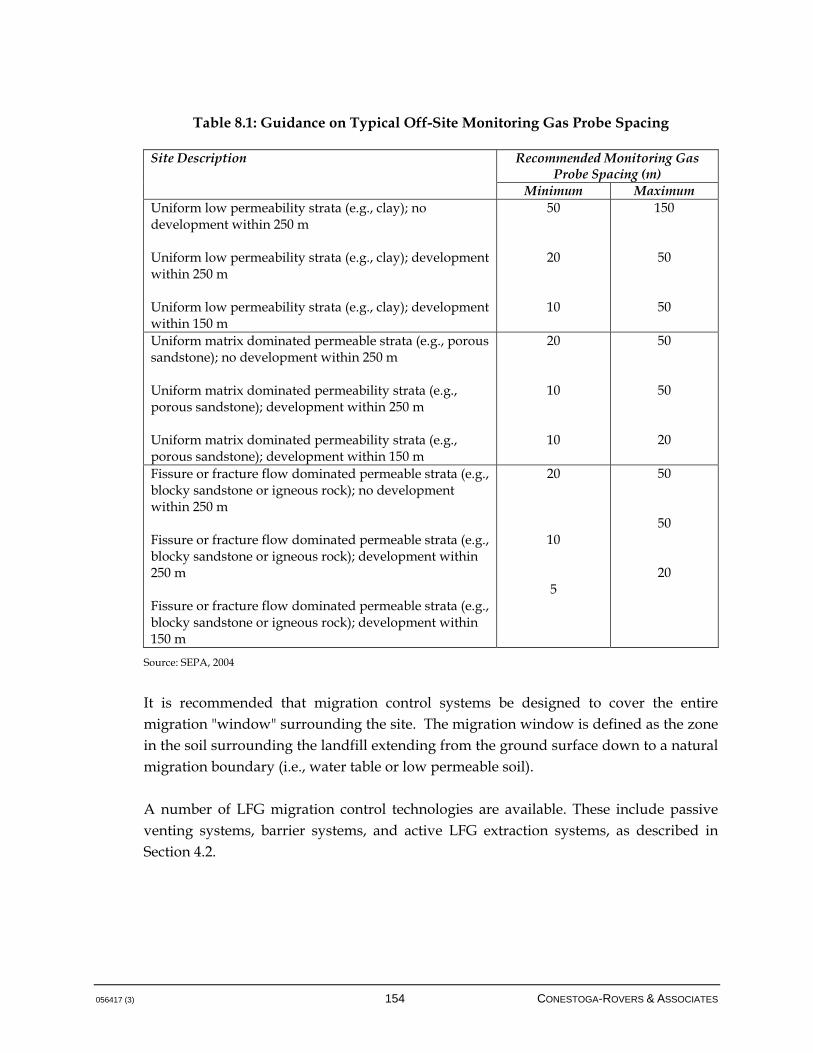
056417 (3) 154 CONESTOGA-ROVERS & ASSOCIATES
Table 8.1: Guidance on Typical Off-Site Monitoring Gas Probe Spacing
Recommended Monitoring Gas Probe Spacing (m)
Site Description
Minimum Maximum Uniform low permeability strata (e.g., clay); no development within 250 m Uniform low permeability strata (e.g., clay); development within 250 m Uniform low permeability strata (e.g., clay); development within 150 m
50
20
10
150
50
50
Uniform matrix dominated permeable strata (e.g., porous sandstone); no development within 250 m Uniform matrix dominated permeability strata (e.g., porous sandstone); development within 250 m Uniform matrix dominated permeability strata (e.g., porous sandstone); development within 150 m
20
10
10
50
50
20
Fissure or fracture flow dominated permeable strata (e.g., blocky sandstone or igneous rock); no development within 250 m Fissure or fracture flow dominated permeable strata (e.g., blocky sandstone or igneous rock); development within 250 m Fissure or fracture flow dominated permeable strata (e.g., blocky sandstone or igneous rock); development within 150 m
20
10
5
50
50
20
Source: SEPA, 2004
It is recommended that migration control systems be designed to cover the entire migration "window" surrounding the site. The migration window is defined as the zone in the soil surrounding the landfill extending from the ground surface down to a natural migration boundary (i.e., water table or low permeable soil). A number of LFG migration control technologies are available. These include passive venting systems, barrier systems, and active LFG extraction systems, as described in Section 4.2.
056417 (3) 155 CONESTOGA-ROVERS & ASSOCIATES
9.0 HEALTH AND SAFETY
A health and safety plan shall be prepared for each landfill site with a LFG management system. This section of the Guideline discusses general health and safety issues related to LFG, but is not intended to be comprehensive. A site-specific health and safety plan that takes into account all pertinent issues and items must be prepared. Any landfill site presents potential health and safety risks. Effective landfill operations require a detailed health and safety plan, operator training, and ongoing attention to safety-related procedures and details. Precautions must be taken to avoid hazardous conditions that may be associated with LFG systems. In addition to the hazards posed by LFG, concerns including high temperatures, high-speed equipment, high-voltage equipment, and noise may be encountered by personnel. All personnel involved with the LFG system must be fully aware of the potential hazards and the protocols required to work safely. The following provides a general overview of the nature of the potential hazards and an introduction to some of the precautionary measures typically taken. It is recommended that individual owner/operators utilize their in-house occupational health and safety resources to develop detailed policies and practices for personnel involved with LFG systems and in accordance with regulatory requirements. LFG may be combustible, suffocating, and toxic. Some trace compounds, such as hydrogen sulphide, found in LFG are toxic at sufficiently high-exposure concentrations. Depending upon its composition, LFG may be lighter than air, heavier than air, or of a similar density. LFG is capable of venting freely from the uncapped surface of the waste as well as migrating through the soil around the landfill. Typical methane concentrations range from 30 to approximately 65 percent by volume in LFG. Methane is explosive in concentrations ranging from 5 to 15 percent by volume in air. As indicated in Section 2.0, 5 percent by volume in air is referred to as the LEL of methane; 15 percent by volume in air is referred to as the Upper Explosive Limit (UEL). Given the composition at which LFG is generated, it is generally inevitable that an interface exists at some location wherein methane concentrations fall within the explosive range. LFG that contains methane below the LEL may become more concentrated until it reaches the explosive range, if it is allowed to accumulate in an enclosed space and displace available air. Because of these variable properties, extreme caution must be exercised when LFG may be present. When working in the vicinity of a landfill site, it is generally prudent to assume that LFG is present within the explosive
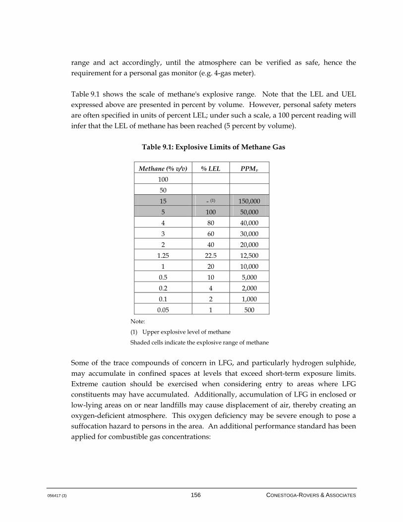
056417 (3) 156 CONESTOGA-ROVERS & ASSOCIATES
range and act accordingly, until the atmosphere can be verified as safe, hence the requirement for a personal gas monitor (e.g. 4-gas meter). Table 9.1 shows the scale of methane's explosive range. Note that the LEL and UEL expressed above are presented in percent by volume. However, personal safety meters are often specified in units of percent LEL; under such a scale, a 100 percent reading will infer that the LEL of methane has been reached (5 percent by volume).
Table 9.1: Explosive Limits of Methane Gas
Methane (% v/v) % LEL PPMv
100
50
15 - (1) 150,000
5 100 50,000
4 80 40,000
3 60 30,000
2 40 20,000
1.25 22.5 12,500
1 20 10,000
0.5 10 5,000
0.2 4 2,000
0.1 2 1,000
0.05 1 500
Note:
(1) Upper explosive level of methane
Shaded cells indicate the explosive range of methane
Some of the trace compounds of concern in LFG, and particularly hydrogen sulphide, may accumulate in confined spaces at levels that exceed short-term exposure limits. Extreme caution should be exercised when considering entry to areas where LFG constituents may have accumulated. Additionally, accumulation of LFG in enclosed or low-lying areas on or near landfills may cause displacement of air, thereby creating an oxygen-deficient atmosphere. This oxygen deficiency may be severe enough to pose a suffocation hazard to persons in the area. An additional performance standard has been applied for combustible gas concentrations:
056417 (3) 157 CONESTOGA-ROVERS & ASSOCIATES
Performance Standard 4 All personnel should make every effort to become fully aware of the nature and hazards of LFG, and the precautionary measures to be taken to avoid accident or injury. A further and important performance standard has been applied regarding the LFG management system in terms of health and safety. While the overall efficiency of the management system may be high, it is important nevertheless to stipulate a standard regarding on-site health and safety. The following design standard has been set: Design Standard 10 An on-site building is defined as any structure or facility with walls, a roof, and a foundation, and that is accessible by people. A building that is elevated and not in contact with the soil below the ground surface does not qualify as a "building" in this definition, and therefore does not require monitoring for combustible gas concentrations. However, vents should be installed within all buildings that do not require air monitoring as per this definition. As part of best management practice, and assuming that an enclosed structure with ventilation controls is applicable, it is mandatory to have trigger levels for warning followed by alarm conditions prior to reaching potentially explosive/combustible conditions in the indoor air environment. For example, in the event that 20 percent of the lower explosive limit of methane has been reached and the final alarm threshold is triggered, an alarm condition should be created that results in evacuation of the building. Note that, as with any equipment, gas sensors should be tested and calibrated according to manufacturer's specifications. An entire series of design features and criteria is applicable to building protection and must be observed, which is beyond the scope of
All buildings on the landfill site must have continuous combustible gas measurement equipment.
Combustible gas concentrations measured in on-site buildings cannot exceed 20 percent of the lower explosive limit of methane (1 percent by volume) at any time.

this document, but will generally include items such as: building air exchange rates, instrumentation and control to link alarm system triggers to air exchange equipment, remote notification of alarms, special construction such as explosion-proof electrical devices and wiring, explosion release mechanisms for the structure, and a number of other measures that can be used individually or in combination. There is also the potential to install soil gas probes near the building that intersects the landfill and the building for additional protection against LFG migration. 9.1 CONFINED SPACES
Entry into and work in confined spaces is generally governed by provincial occupational Health and Safety Legislation. A site-specific standard operating procedure is required for each site where confined space entry may be necessary. The following information is intended to introduce personnel to the hazards of confined space entry at or near landfills. This section should be considered introductory only, and any personnel required to carry out confined space entry must be fully trained and competent in the procedures detailed in the applicable Health and Safety Legislation. Typically, air monitoring is conducted prior to confined space entry. Accumulation of LFG may result in the displacement of oxygen by methane and the denser carbon dioxide within chambers, sewers, underground structures, and low-lying ditches adjacent to landfills. LFG may also migrate through the soil surrounding the landfill. There have been reported incidents of workers without proper gas detection equipment entering confined spaces on or near landfills and being asphyxiated. Confined spaces associated with LFG systems may include the following: Below-grade structures or chambers on or near the landfill, including manholes
Pumping stations
Buildings or rooms that contain piping conveying LFG
Low-lying areas or excavations
Chambers for LFG extraction wells, horizontal collection trenches, subheader isolation control valves, or header cleanout chambers
9.2 LOCKOUT TAGOUT
Procedures must be followed to ensure that equipment being worked on is isolated from all potential hazardous energy sources and is locked out or tagged out before any individual performs any servicing or maintenance activity where an unexpected

energization, startup, or release of energy could cause an injury. Energy sources can be electrical, mechanical, hydraulic, pneumatic, chemical, thermal, or other. Specific procedures and rules must be developed and obeyed for the following: Lockout/tagout involving one or more than one person
Proper use of energy isolating devices
Release of stored energy
Procedure for testing or positioning activities
Documentation and record keeping
Applicable legislation, regulations, guidelines, and standards are available that describe the specific lockout or tagout procedures to be followed. 9.3 AIR MONITORING FOR DRILLING AND CONSTRUCTION WORK
There is a health and safety concern due to the potential for exposure to high concentrations of LFG during drilling and construction operations at or near a landfill site, such as during the installation of vertical LFG extraction wells. The following suggests minimum air monitoring requirements and action levels. Monitoring and personal protection equipment should be in good working order and used only by those trained in and familiar with its use and limitations. Combustible Gas Action levels are based on the readings from a combustible gas meter. The readings are generally given as a percentage of the LEL and are collected in the general work area. An atmospheric oxygen level of less than 19.5 percent may affect the readings from a combustible gas meter and give lower-than-actual levels. Table 9.2 outlines the action levels for general non-confined space readings.
Table 9.2: Combustible Gas Action Levels for Non-Confined Space Readings 0-10% LEL Continue working and monitoring atmosphere for combustible gases. Inform
personnel working in the area whenever readings are 5% LEL or greater. 10-20% LEL Continue working with caution. Inform personnel working in area of readings.
Be prepared to cease operations. >20% LEL Cease operations and move to a safe place. Reevaluate work plan. Engineering
controls such as forced ventilation and use of non-sparking tools are to be implemented if operations are to continue. DO NOT CONTINUE WORKING UNTIL CONDITIONS ARE CONSISTENTLY BELOW 20% LEL.

Note: Hot work is to be conducted only at 0% LEL.
For field work that is not being conducted within a waste disposal site, the action levels for combustible gas readings taken at or near the borehole rather than in the general area are outlined in Table 9.3.
Table 9.3: Combustible Gas Action Levels for Off-Site Borehole Readings
Instrument Reading
Action to be taken
0-20% LEL Continue working and monitoring atmosphere for combustible gases. Inform personnel working in the area whenever readings are >10% LEL
20-40% LEL Continue working with caution. Inform personnel in area of readings. Be prepared to cease operations.
>40% LEL Cease operations and move to a safe area. Reevaluate work plan. Engineering controls such as forced ventilation and use of non-sparking tools are to be implemented if operations are to continue. DO NOT CONTINUE WORKING UNTIL CONDITIONS ARE CONSISTENTLY BELOW 40% LEL. Supplied air or self-contained breathing apparatus (SCBA) may be necessary.
Oxygen A direct reading oxygen meter is used to determine the percentage of oxygen in the atmosphere. Table 9.4 outlines the action levels for oxygen readings in all areas of the site.
Table 9.4: Oxygen Action Levels for All Readings
Instrument reading
Action to be taken
<19.5% or >23.5%
Cease operations and move to a safe area. Re-evaluate work plan. Engineering controls such as forced ventilation and use of non-sparking tools are to be implemented if operations continue. DO NOT CONTINUE WORKING UNTIL OXYGEN LEVELS ARE BETWEEN 19.5 AND 23.5 %. When oxygen levels are outside this range, combustible gas meter readings may not be reliable. Supplied air or Self-Contained Breathing Apparatus (SCBA) may be necessary.
Hydrogen Sulphide (H2S) Whenever readings approach 10 ppm on a direct reading H2S meter, cease work immediately and move to a safe area. H2S has a threshold limit value (TLV) of 10 ppm. Exposure to even low concentrations of H2S can cause olfactory fatigue, which impairs the ability to detect the characteristic H2S odour. Air purifying respirators with organic vapour cartridges are not suited for exposure to H2S.
056417 (3) 161 CONESTOGA-ROVERS & ASSOCIATES
Hydrogen Sulphide (H2S) Whenever readings approach 10 ppm on a direct reading H2S meter, cease work immediately and move to a safe area. H2S has a threshold limit value (TLV) of 10 ppm. Exposure to even low concentrations of H2S can cause olfactory fatigue, which impairs the ability to detect the characteristic H2S odour. Air purifying respirators with organic vapour cartridges are not suited for exposure to H2S.
056417 (3) 162 CONESTOGA-ROVERS & ASSOCIATES
10.0 SURFACE EMISSIONS MONITORING
Although some jurisdictions have a requirement for surface emissions monitoring, with specification of remedial actions to be taken if surface emissions exceed a threshold value, this monitoring technique may be more appropriate as a best management practice as it relates to landfill and LFG management system operation. Surface emissions monitoring can be used to identify hot spots (areas of high LFG concentration near landfill surface) and to qualitatively assess the performance of a landfill cover system. One of the primary limitations to surface emissions monitoring is that the sample size and sampling location do not provide an emissions concentration or flux that is representative of the site's true mean. If the intent of surface emissions monitoring is to develop a pseudo-mass balance around LFG produced, attenuated through cover, migrated through the subsurface, and extracted by a LFG management system, a statistically-valid assessment of surface emissions is likely required but often impractical. As part of a best management practice, surface emissions monitoring is more appropriate for identifying issues with the cover system that poor or degraded areas of landfill cover as evidenced by readings or vegetation distress, or as it may affect the operations of a LFG management system by allowing air intrusion. 10.1 POINT SAMPLING
10.1.1 PORTABLE GAS DETECTORS
Portable gas detectors are hand-held or mounted devices that typically utilize one of the following methods of analysis: flame ionization, thermal conductivity, or photoionization. Flame ionization detectors (FID) are most commonly used for landfill applications. When held 5-10 cm (2-4 inches) above the surface, they can capture point source emissions. Portable FID detectors typically cost $5,000 - 10,000 (Yesiller, Hanson, 2008). The success of these technologies in providing a representative analysis of the site's emissions is largely dependant on the sampling methodology. A poor sampling scheme can potentially miss hot spots. Under the California Integrated Waste Management Board guidelines, portable gas detectors are used for instantaneous landfill surface monitoring. The landfill is separated into a grid and samples are taking quarterly. The allowable limit for methane concentration is 500 ppmv above background concentrations (SCAQMD, 2000).
056417 (3) 163 CONESTOGA-ROVERS & ASSOCIATES
Under English and Welsh guidelines, portable gas detectors are used in the first stage of monitoring emissions through a landfill cap. The initial walkover of the site is done in a systematic fashion close to the surface. If the results indicate that methane concentrations are greater than 100 ppmv above the landfill cap or greater than 1,000 ppmv near features such as wellheads, a second stage of monitoring is triggered. The second stage of monitoring involves using flux chambers, as will be described in the next section. The frequency of walkover surveys is event- or regulatory-driven and is required after any remedial works have taken place on site (SEPA, 2004). 10.1.2 STATIONARY ENCLOSURE TECHNIQUES
Stationary enclosure techniques typically refer to the static flux chamber. Static flux chambers collect gas from discrete locations in a sealed chamber for analysis. The chamber is driven into the upper 5-20 cm of the landfill to form a seal for gas collection. Samples are extracted from ports on the chamber and analyzed with gas chromatography in the field or sent to the lab for analysis. Continuous measurements can be made to determine the flux. Static flux chambers typically cost $150 per sample (Yesiller, 2008). Under English and Welsh guidelines, flux chambers are used in the second stage of monitoring. In this stage, the landfill is divided into homogeneous and hot spot strata. These strata are then subdivided into consistent geometric patterns, considering visually obvious emission features. Flux measurements should not be taken after heavy rainfall or with standing water on-site. Barometric pressure should be within normal averages and should not be rising quickly. Flux chambers are to be measured for one hour and the average flux for each zone is to be calculated. According to the guidelines, the emission standards for each zone must not exceed 0.001 mg/m2/s for permanently capped zones and 0.1 mg/m2/s for temporarily capped zones. Generally, flux chamber use on landfills is laborious. Sealing a flux chamber against a vegetated cover is often difficult and the testing procedure requires a discrete amount of time at each monitoring location. Often, an inert gas supply is recommended as influent to the flux chamber in order to prevent contamination via compounds present in atmospheric air.

056417 (3) 164 CONESTOGA-ROVERS & ASSOCIATES
10.1.3 MOBILE ENCLOSURE TECHNIQUES
Mobile enclosure techniques involve obtaining instantaneous or continuous air samples using an enclosure device; Summa Canisters or Tedlar bags are often used for this purpose. Summa Canisters are evacuated stainless steel canisters that provide instantaneous or continuous air samples. Stainless steel does not allow volatile compounds to escape and limits photo-degradation. Summa Canisters do not require a pump and can be evacuated to negative pressures of 30 inches of mercury. Continuous air samples can be obtained by using a flow controller connected to the valve. Without the flow controller instantaneous samples are obtained. Field samples are typically sent to an analytical laboratory for gas chromatography and mass spectrometry (GC/MS) analysis (Maxxam Analytics, 2008). Tedlar bags are used for air sample collection with a rotameter (flow meter), collection probe, pump, and a container to shield the bag from photo-degradation. The pump fills the bag with the sample at a flow rate (50-200 mL/min) for a specified amount of time to determine the concentration (Air Toxics Ltd, 2007). The disadvantage of this setup is that a power source is required and the samples must also be sent to the lab for GC/MS analysis. Under the California guidelines, Tedlar bags are used for integrated landfill surface sampling, gas collection sampling, and ambient air sampling. During the integrated landfill surface sampling event, 8-10 L are sampled monthly from a section of the site's grid. Wind speed must be less than 8 km/hour during collection and there must be no precipitation within the last 72 hours. The analytical results must be less than 50 ppmv total organic compounds measured as methane including several carcinogenic and toxic air contaminants (SCAQMD, 2000). For the gas collection system, samples are taken from the headers that enter the gas management system. For this event, a 10 L bag must be filled for 10 minutes monthly (SCAQMD, 2000). Ambient air samples are collected at the property boundary upwind and downwind over two 12-hour periods starting in the morning and the evening each month. Wind speed and direction must be recorded to determine sampling conditions (SCAQMD, 2000).
056417 (3) 165 CONESTOGA-ROVERS & ASSOCIATES
10.2 OPTICAL REMOTE SENSING
Optical remote sensing is used to measure non-point source emissions to determine hot spots and flux. Laser techniques include tunable diode laser spectroscopy (TDL), optical feedback cavity enhanced absorption spectroscopy, differential absorption lidar, ultraviolet differential optical absorption spectroscopy, and Fourier transform infrared spectroscopy (FTIR). TDL utilizes a laser that is tuned to the absorption frequency of LFG (1,300 – 1,700 nanometres [nm]). To calculate the flux, additional software/algorithms are required (e.g. VRPM used by EPA and approved as OTM-10). Paths up to 1km in length can be used with TDL. The capital costs for TDL and FTIR equipment are approximately $75,000 and $125,000, respectively (Yesiller, Hanson 2008). TDL has been shown to be most sensitive to calibration height and surface roughness (Golder Associates, 2009). Currently, this method is not commonly used because it is largely in the research and development stage, particularly for estimating flux. It is designed for well-defined emission sources that are small in relation to the vertical plane of the optical sensor. Landfills do not have well-defined emission sources and the stratigraphy tends to be heterogeneous with cracks and fissures causing multiple sources that can be large in comparison to the vertical plane of the optical sensor (Yesiller, 2008). 10.3 TRACER TESTING
For tracer testing, an inert gas (i.e., sulphur hexafluoride or nitrous oxide) is released upwind of the emission source. The concentration of LFG emissions can be determined from their differential concentration and mixing with the tracer gas (Yesiller, Hanson 2008). The tracer release pattern should be similar to the LFG emission pattern. This pattern is often unknown prior to sampling and may result in a potential source of error (Golder Associates, 2009). Furthermore, tracer testing is influenced by off-site weather conditions that may cause additional mixing of the inert gas and the LFG emissions (Yesiller, 2008). Further, sulphur hexafluoride is a powerful GHG, with a global warming potential equal to roughly 24,000 times that of carbon dioxide.
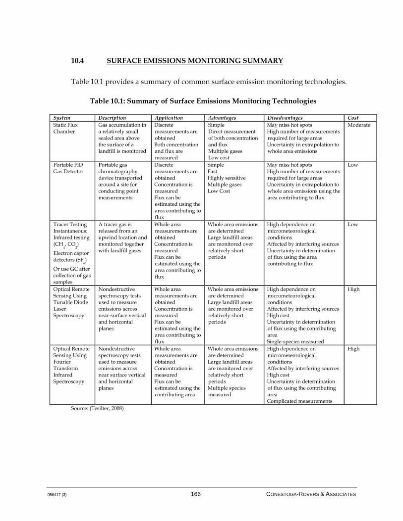
056417 (3) 166 CONESTOGA-ROVERS & ASSOCIATES
10.4 SURFACE EMISSIONS MONITORING SUMMARY
Table 10.1 provides a summary of common surface emission monitoring technologies.
Table 10.1: Summary of Surface Emissions Monitoring Technologies
System Description Application Advantages Disadvantages Cost Static Flux Chamber
Gas accumulation in a relatively small sealed area above the surface of a landfill is monitored
Discrete measurements are obtained Both concentration and flux are measured
Simple Direct measurement of both concentration and flux Multiple gases Low cost
May miss hot spots High number of measurements required for large areas Uncertainty in extrapolation to whole area emissions
Moderate
Portable FID Gas Detector
Portable gas chromatography device transported around a site for conducting point measurements
Discrete measurements are obtained Concentration is measured Flux can be estimated using the area contributing to flux
Simple Fast Highly sensitive Multiple gases Low Cost
May miss hot spots High number of measurements required for large areas Uncertainty in extrapolation to whole area emissions using the area contributing to flux
Low
Tracer Testing Instantaneous: Infrared testing (CH
4, CO
2)
Electron captor detectors (SF
6)
Or use GC after collection of gas samples
A tracer gas is released from an upwind location and monitored together with landfill gases
Whole area measurements are obtained Concentration is measured Flux can be estimated using the area contributing to flux
Whole area emissions are determined Large landfill areas are monitored over relatively short periods
High dependence on micrometeorological conditions Affected by interfering sources Uncertainty in determination of flux using the area contributing to flux
Low
Optical Remote Sensing Using Tunable Diode Laser Spectroscopy
Nondestructive spectroscopy tests used to measure emissions across near-surface vertical and horizontal planes
Whole area measurements are obtained Concentration is measured Flux can be estimated using the area contributing to flux
Whole area emissions are determined Large landfill areas are monitored over relatively short periods
High dependence on micrometeorological conditions Affected by interfering sources High cost Uncertainty in determination of flux using the contributing area Single-species measured
High
Optical Remote Sensing Using Fourier Transform Infrared Spectroscopy
Nondestructive spectroscopy tests used to measure emissions across near surface vertical and horizontal planes
Whole area measurements are obtained Concentration is measured Flux can be estimated using the contributing area
Whole area emissions are determined Large landfill areas are monitored over relatively short periods Multiple species measured
High dependence on micrometeorological conditions Affected by interfering sources High cost Uncertainty in determination of flux using the contributing area Complicated measurements
High
Source: (Tesilter, 2008)
056417 (3) 167 CONESTOGA-ROVERS & ASSOCIATES
11.0 RECORD KEEPING AND REPORTING PROCEDURES
As per the requirements within the Regulation and this Guideline, the owner or operator of a landfill site required to install a LFG management facility must maintain records for: The quantity and sources of MSW received for disposal into the landfill site
The composition of MSW received, if the waste composition has been monitored and analyzed
Any maintenance or shutdown of the LFG management facility operated at the landfill site
The quantity and composition of gases collected at the landfill site
The quantity and composition of LFG that is flared or used as an alternative to flaring such as utilization
A record of all LFG collection field monitoring and balancing data
These records must be retained for a period of at least 10 years after they are documented. On written request of the director (BC MOE), an owner or operator of a landfill site must produce the records listed above, within the time period specified by the director (BC MOE). Refer to Section 12.0 for a detailed description of system shutdown. 11.1 ANNUAL REPORTING
An annual monitoring report must be filed to the director (BC MOE), as outlined in Section 14 of the Regulation, and must include: The quantity and sources of MSW received for disposal into the landfill site
The composition of MSW received, if the waste composition has been monitored and analyzed
A description of any organics diversions program used at the landfill site
The total annual quantity and annual average composition of gases collected at the landfill site
An explanation for the total quantity and annual average composition of LFG collected if these are less than expected

056417 (3) 168 CONESTOGA-ROVERS & ASSOCIATES
The total annual quantity and average annual composition, determined in accordance with the methodology set out in the guidelines, of landfill gas that is flared or used as an alternative to flaring such as utilization
If LFG is used as an alternative to flaring, a description of that use
A calculation of the LFG management facility’s collection efficiency utilizing the methodology presented in this Guideline
A description of any periods when the LFG management facilities were shutdown
A description of any significant maintenance or operational problems encountered
An evaluation of the existing collection efficiency and plans for increasing the facilities' efficiency, particularly if the 75 percent collection efficiency was not obtained during the operation of the system
Any available municipal solid waste composition studies
A description of LFG collection field issues encountered, including a summary of major repairs necessary, field monitoring and balancing frequency, and any odour complaints received
Any plans to be implemented at the landfill site in the next reporting year for modifications or other changes to LFG management facilities and periods when the LFG management facilities will be out of operation
A description of any performance standard within this Guideline that was not met during the previous year, and plans to attempt to meet these standards during the following operational year
Any additional information requested in writing by the director (BC MOE)
It may be possible to include the information required in the LFG management systems annual monitoring report with the landfill annual report. The BC MOE should be consulted to confirm that this approach is acceptable.
056417 (3) 169 CONESTOGA-ROVERS & ASSOCIATES
12.0 SYSTEM SHUTDOWN
12.1 TEMPORARY SHUTDOWN
As per the Regulation, the owner or operator of a landfill site where LFG management facilities are shut down temporarily for emergency maintenance or replacement must notify the director (BC MOE) with 24 hours of the shutdown by phone, fax, or other electronic means. There are situations where a LFG management system will be shut down, either for maintenance or as a result of field conditions. It is possible for methane composition to decrease below limits for flare operation; more importantly, oxygen content may increase beyond safe conditions, resulting in flare shutdown. Sudden breakages in wellhead or subsurface piping can occur, condensate traps may be drawn dry, temporary repairs of LFG systems may introduce air into the system, and a variety of other conditions may occur. Periodically, maintenance to critical LFG components will be required, such as to blowers or flares, requiring downtime. If additional vertical wells are to be installed in the LFG collection field, local wells may need to be closed to prevent air intrusion into the new boreholes, which may limit the supply of methane needed for combustion. The expansion of a well field should not result in temporary shutdown of the system. Blind flanges should be included in the design of future areas of the collection field, and overall good planning of the LFG management system installation can mitigate shutdown due to system expansion, which should be the goal of any system. Note that for many of the above conditions that relate to intrusion of air into the system and increased oxygen/diminished methane conditions, routine maintenance, monitoring, and balancing of the well field can avoid these situations. Regular monitoring of consolidated monitoring locations (such as at subheader control valves or at horizontals) can rapidly diagnose and isolate potential problem areas of the LFG control field. Routine inspection of condensate traps and priming of p-traps can help to ensure that these locations do not become intrusion points. Understanding and effective control of the leachate collection system as it relates to the LFG control system is also important in this respect. The flare station should be equipped with a Run Stop button to facilitate shutdown, if required. Automated shutdown should be prescribed based on the required combustion conditions for the flare and based on oxygen content; generally, it is advisable to shut down the main LFG draw system if oxygen content exceeds 4 percent by volume. Note

056417 (3) 170 CONESTOGA-ROVERS & ASSOCIATES
that reciprocating engine technology for utilization may prescribe an even lower set point on oxygen content, and will have more stringent minimum methane composition expectations for continued operation. 12.2 PERMANENT SHUTDOWN PROCEDURES
Section 11 of the Regulation provides a procedure (as outlined below) for permanent shutdown of LFG management facilities. At least 90 days before the date an owner or operator of a landfill site plans to cease operation of LFG management facilities, the owner or operator must submit to the director (BC MOE) a shutdown report prepared by a qualified professional. The shutdown report must include certification by a qualified professional that the quantity of methane generated at the landfill site per year, calculated in accordance with the methodology set out in the LFG Generation Assessment Procedure Guidance Report, is less than 500 tonnes. The report must address other factors such as odour, migration, health, etc. to prove that the operation of the LFG management system is no longer required with respect to health and safety of the public. An owner or operator of a landfill site must continue to operate and maintain LFG management facilities in accordance with the accepted design plan for the landfill site until the director has accepted the shutdown report under Section 18 of the Regulation. It may be financially beneficial for a landfill owner or operator to continue to operate the LFG management system at a LFG generation rate of less than 500 tonnes methane per year, although no longer mandatory. The capital works would be in place and the repayment of the capital cost may be complete. Continued voluntary LFG collection and flaring/utilization would potentially qualify for carbon credits, although the rules base for carbon credit creation at the time should be consulted. There are also environmental benefits associated with the continuation of the LFG management system operation. The decision to permanently shut down a LFG management system should be made on a site-specific basis.

056417 (3) 171 CONESTOGA-ROVERS & ASSOCIATES
13.0 LANDFILL GAS UTILIZATION
The utilization of LFG for the generation of useful products such as electricity, natural gas, or fuel for boilers and furnaces has been ongoing for a number of years and is currently growing in prevalence as interest in renewable energy sources increases and the economics of LFG utilization continue to improve. Specifically, anticipated shortages of and/or reluctance to consume fossil-fuel-based energy generation has increased investment in renewable energy. Furthermore, the reduced cost of the technology and the increase in energy sale prices continue to improve the viability of LFG utilization. The economic return from utilizing collected LFG can defray some of the costs of operation and maintenance of a landfill. Currently, a trend is developing towards offering subsidized pricing over long-term periods to motivate the development of LFG utilization. Almost exclusively, this has occurred for electricity generation projects, which comprise the vast majority of LFG utilization projects worldwide. The technology is relatively established, and the primary risks related to the projects are related to the supply of LFG rather than to the utilization technology itself. The growing awareness of energy conservation and environmental issues has motivated municipalities as well as private developers to investigate and in some cases harness and utilize LFG as a resource. In Canada, most of the utilization projects have been either small-scale direct use applications or large-scale electrical generation. Emerging LFG utilization technologies are also expanding the range of viable projects even further. A LFG utilization feasibility study should be conducted prior to deciding to proceed with LFG utilization. There are many factors that should be considered in the assessment, including the expected landfill closure year, the economics of the project (capital and operational and maintenance costs versus any revenue from energy sales), size requirements for the equipment for the project, etc. Some LFG utilization project options may be supported even at smaller landfills depending on the available gas and the pertinent economics. As previously mentioned for the LFG extraction plant, CAN/CGA-B105-M93, the Canadian Gas Association's "Code for Digester Gas and Landfill Gas Installations" and all other applicable standards should be consulted for specific information and requirements when engaging in the design and operation and maintenance of LFG utilization systems. Practitioners should seek to remain abreast of additional requirements as they emerge.
056417 (3) 172 CONESTOGA-ROVERS & ASSOCIATES
13.1 LFG PRE-TREATMENT
To employ most LFG utilization technologies, the raw collected biogas needs to be processed to some extent. The degree of LFG processing or pre-treatment required is a function of the constituents and levels of traces compounds in the biogas, the utilization option to be employed, and the degree to which these constituents influence operations and maintenance costs. The main constituents in LFG requiring pre-treatment include: Free moisture/water vapour
Particulates
Hydrogen sulphide
Siloxanes
Halogenated organic compounds
Carbon dioxide
Most LFG utilization projects at minimum require the removal of moisture and particulates. Most primary treatment technologies rely on physical processes for moisture and particulate removal. Hydrogen sulphide, siloxanes, halogenated hydrocarbons, and carbon dioxide usually require more advanced removal technologies. Secondary treatment of the LFG may be also be necessary to remove any additional hydrogen sulphide, siloxanes, halogenated organic compounds, and carbon dioxide. In some cases, the composition of waste can have a significant effect on LFG utilization. For example, gypsum, a major component of drywall, may liberate sulphates when wetted in the landfill environment, producing high levels of hydrogen sulphide. Additionally, input of compost that has turned anaerobic into a landfill environment has been demonstrated to produce levels of hydrogen sulphide as high as 10,000 ppm; these elevated levels are possible because of the high organic loading of this material. Siloxanes are well known to originate from the presence of cosmetic residues in landfills and from the input of wastewater sludge rich in siloxanes. Siloxane concentrations in LFG typically range from 0.5 to 15 mg/m3. Halogenated organic compounds are typically not present in concentrations of concern in LFG, and are generally present at under 100 mg/m3. Given that the composition of waste placed in a landfill can be highly variable, it is critical to assess actual LFG trace constituents to determine the appropriate level of pre-
056417 (3) 173 CONESTOGA-ROVERS & ASSOCIATES
treatment for utilization applications. Generally, literature-supplied data regarding trace compound concentrations is only useful in identifying potential compounds of concern. The relative amounts of these compounds must be ascertained on a case-by-case basis through testing, and it is recommended that such testing be undertaken prior to selecting a utilization option. 13.1.1 MOISTURE
Moisture present in the LFG can drastically reduce system efficiency and form corrosive mixtures in combination with other contaminants. Moisture present in LFG can create numerous problems throughout the piping network. Condensed water vapour can accumulate in piping, increase pressure losses or create full blockages, and leave deposits on pipe walls. So-called "bellies" can develop in piping systems that are often manifested as swings in vacuums or pressures as a result of water slugs. Condensed water can be particularly problematic in areas with cold climates. Dust and particulates are also problematic in LFG utilization projects, as they can have abrasive properties and thus can potentially cause significant wear on utilization equipment. In many cases, particulates are often the nucleus on which water droplets condense and are therefore effectively removed with certain moisture removal technologies. Often, supplemental particulate removal, if required, can be achieved by simply placing a filter on the outlet of moisture removal technologies. In most cases, inexpensive primary treatment technologies for moisture and particulate removal should be included in LFG utilization projects. Primary treatment can significantly reduce wear on utilization equipment and is generally always provided when considering utilization. 13.1.2 SULPHUR COMPOUNDS
Sulphur compounds, especially hydrogen sulphide, are corrosive in the presence of free water or moisture. Sulphur can be absorbed by water present in engine oil to produce sulphuric acid. Sulphuric acid can lead to premature corrosion in the LFG piping network, treatment units, and utilization units. Sulphuric acid is especially hard on engine parts and leads to excessive wear on engine components such as piston rings, and cylinder linings. Also, acidification of the engine oil by sulphuric acid requires increased maintenance costs for more frequent oil changes.
056417 (3) 174 CONESTOGA-ROVERS & ASSOCIATES
The degree of pre-treatment required depends on the chosen utilization technology, as some units can tolerate higher hydrogen sulphide concentrations than others. For example, typical boilers can withstand concentrations of hydrogen sulphide up to 1,000 ppm, while internal combustion engines operate best when hydrogen sulphide is maintained below 100 ppm (Wellinger and Linberg, 2000). As mentioned previously, the effects of hydrogen sulphide on internal combustion engines can be minimized by changing the engine oil more frequently. Microturbines are more hydrogen sulphide tolerant, withstanding concentrations up to 70,000 ppm when parts in the microturbine have been retrofitted to withstand the acid (Capstone Turbine Corporation, 2002). Corrosion caused by hydrogen sulphide in LFG can destroy expensive utilization equipment long before the end of its normal life cycle. Even though technologies exist for the simultaneous removal of hydrogen sulphide and other contaminants, it is recommended that hydrogen sulphide removal, if necessary, be achieved early in the utilization network to minimize corrosion in piping networks and units prior to the removal module. The use of LFG may be limited in practical situations by the presence of high levels of hydrogen sulphide. 13.1.3 SILOXANES
The main concern with siloxanes is the deposition of siliceous materials on exposed heat exchanger, reciprocating engine, and combustion turbine parts. During combustion, and to lesser extent heating, siloxanes are converted to abrasive crystalline silicon dioxides, which are deposited on interior surfaces. These deposits have physical properties similar to those of glass, and are generally opaque, white to light gray, and may exhibit poor crystalline structure. These deposits increase wear and severely reduce the lifespan of utilization equipment. They also act as a thermal insulator and contribute to overheating of sensitive engine parts. Once deposits are formed, equipment must be stripped down and the solids manually scraped from affected surfaces such as pistons, cylinder heads, and valves in reciprocating engines. In many cases, siloxane-related deposits can be most economically managed with increased maintenance and in-engine management strategies. While maintenance costs can be reduced by removing siloxanes prior to deposition on exposed surfaces, it does not currently appear that siloxane removal is a cost-effective solution in most cases. However, manufacturers of reciprocating engines and combustion turbines specify tolerances for siloxanes in LFG due to potential siloxane-related equipment failure.
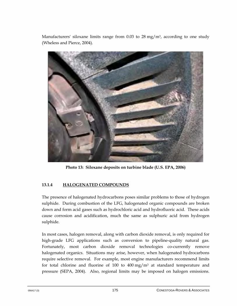
056417 (3) 175 CONESTOGA-ROVERS & ASSOCIATES
Manufacturers' siloxane limits range from 0.03 to 28 mg/m3, according to one study (Wheless and Pierce, 2004).
Photo 13: Siloxane deposits on turbine blade (U.S. EPA, 2006) 13.1.4 HALOGENATED COMPOUNDS
The presence of halogenated hydrocarbons poses similar problems to those of hydrogen sulphide. During combustion of the LFG, halogenated organic compounds are broken down and form acid gases such as hydrochloric acid and hydrofluoric acid. These acids cause corrosion and acidification, much the same as sulphuric acid from hydrogen sulphide. In most cases, halogen removal, along with carbon dioxide removal, is only required for high-grade LFG applications such as conversion to pipeline-quality natural gas. Fortunately, most carbon dioxide removal technologies co-currently remove halogenated organics. Situations may arise, however, when halogenated hydrocarbons require selective removal. For example, most engine manufacturers recommend limits for total chlorine and fluorine of 100 to 400 mg/m3 at standard temperature and pressure (SEPA, 2004). Also, regional limits may be imposed on halogen emissions.

056417 (3) 176 CONESTOGA-ROVERS & ASSOCIATES
Technologies do exist for selective halogen removal such as pressure swing adsorption. However, a careful economic analysis should be performed prior to implementation. 13.1.5 PRE-TREATMENT SELECTION
A biogas pre-treatment technology selection grid is included on Figure 13.1. It is noted that this selection grid is intended to provide reference and input information into the decision-making process, but cannot identify every potential combination of pre-treatments required for all situations. Every project needs to be assessed on a site-specific basis with appropriate inputs. On the most basic level, as indicated in the selection grid, there will almost always be a moisture removal component of biogas pre-treatment. This includes removal of liquid moisture via condensate traps or removal of water vapour through other means. However, selection of pre-treatment technologies beyond this is dependant on a number of different factors.
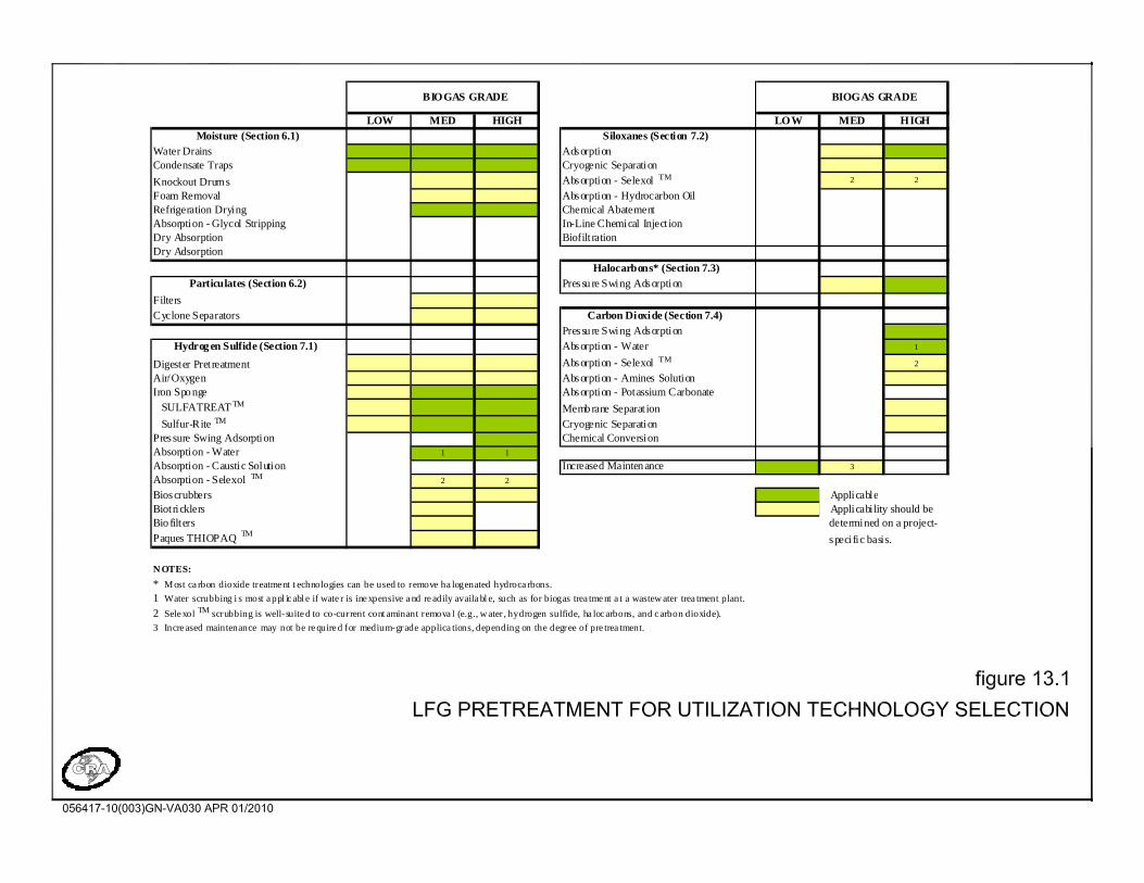
LOW MED HIGH LOW MED HIGH
Moisture (Section 6.1) Siloxanes (Section 7.2) Water Drains AdsorptionCondensate Traps Cryogenic SeparationKnockout Drums Absorption - Selexol TM 2 2
Foam Removal Absorption - Hydrocarbon Oil Refrigeration Drying Chemical AbatementAbsorption - Glycol Stripping In-Line Chemical Inject ion Dry Absorption Biofilt rationDry Adsorption
Halocarbons* (Section 7.3)Particulates (Section 6.2) Pressu re Swing Adsorption
FiltersCyclone Separators Carbon Dioxide (Section 7.4)
Pressu re Swing Adsorption Hydrog en Sulfide (Section 7.1) Absorption - Water 1
Digester Pret reatment Absorption - Selexol TM 2
Air/Oxygen Absorption - Amines Solution Iron Sponge Absorption - Potassium Carbonate SULFATREAT TM Membrane Separat ion Sulfur-Rite TM Cryogenic SeparationPressure Swing Adsorption Chemical ConversionAbsorption - Water 1 1
Absorption - Caustic Solution Increased Mainten ance 3
Absorption - Selexol TM 2 2
Bioscrubbers ApplicableBiotricklers Applicability should beBio filters determined on a project-Paques THIOPAQ TM speci fic basis.
N OTES:
* Most ca rbon dioxide treatme nt t echnologies can be used to remove ha logenated hydroca rbons.1 Water scrubbing i s most a ppl ic abl e if wate r is ine xpensive a nd re adily availa bl e, such as for biogas trea tme nt a t a wastew ater trea tment plant.2 Sele xol TM scrubbing is well-suite d to co-current cont aminant remova l (e.g., w ater , hydrogen sulfide, ha loc arbons, and c arbon dioxide). 3 Incre ased maintenance may not be re quire d for medium-grade applica tions, depending on the degree of pre trea tment.
BIOGAS GRADE BIOGAS GRADE

056417 (3) 178 CONESTOGA-ROVERS & ASSOCIATES
13.2 POTENTIAL UTILIZATION APPLICATIONS
This section discusses different methods of LFG utilization applications. The selection of utilization options available for a LFG management project depends largely on the following factors: LFG quality with respect to the previously-discussed contaminants of concern
Degree of treatment required to meet contaminant limits for the utilization option
Amount of biogas produced, or scale of the project
Economic viability and the applicable energy sales price and term
Generally, biogas can be classified into three categories, based on the level of treatment or upgrading required prior to utilization. Table 13.1 describes the categories for biogas fuel grades (CRA, 2007).
Table 13.1: Description of Biogas Fuel Grades
Low-Grade
Fuel
Low-grade biogas applications include fuel for boilers, furnaces, and
microturbines. It may be desirable to include some degree of hydrogen
sulphide removal in low-grade fuel applications to prevent premature
wear on collection and utilization equipment.
Medium-Grade
Fuel
Medium-grade fuel has a broader range of fuel applications than
low-grade fuel because of the reduction in corrosive constituents. It may
be used in industrial boilers, reciprocating engines, gas turbines, and
combined cycle systems. Costs incurred as a result of processing the
biogas may by offset by a reduction in operation and maintenance costs,
and by the increased life-expectancy of the equipment.
High-Grade
Fuel
High-grade fuel applications include upgrading biogas to pipeline gas
quality, fuel cells, and fuel vehicles.
The heating value of fuels derived from biogas depends primarily on the methane content. Low and medium-grade fuels derived from biogas typically have a heating value of 16.8 MJ/m3. With carbon dioxide removed the heating value of high-grade fuels from biogas increases to approximately 37.3 MJ/m3 (CRA, 1996). High-grade fuels can be directly substituted for natural gas in pipeline applications. The selection of a biogas utilization application must take into account all relevant factors, including energy sales prices, capital and operating costs, and system reliability.
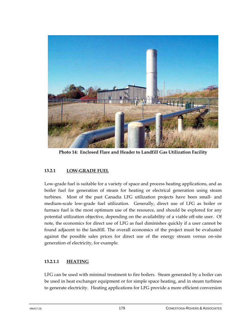
056417 (3) 179 CONESTOGA-ROVERS & ASSOCIATES
Photo 14: Enclosed Flare and Header to Landfill Gas Utilization Facility
13.2.1 LOW-GRADE FUEL
Low-grade fuel is suitable for a variety of space and process heating applications, and as boiler fuel for generation of steam for heating or electrical generation using steam turbines. Most of the past Canadia LFG utilization projects have been small- and medium-scale low-grade fuel utilization. Generally, direct use of LFG as boiler or furnace fuel is the most optimum use of the resource, and should be explored for any potential utilization objective, depending on the availability of a viable off-site user. Of note, the economics for direct use of LFG as fuel diminishes quickly if a user cannot be found adjacent to the landfill. The overall economics of the project must be evaluated against the possible sales prices for direct use of the energy stream versus on-site generation of electricity, for example. 13.2.1.1 HEATING
LFG can be used with minimal treatment to fire boilers. Steam generated by a boiler can be used in heat exchanger equipment or for simple space heating, and in steam turbines to generate electricity. Heating applications for LFG provide a more efficient conversion
056417 (3) 180 CONESTOGA-ROVERS & ASSOCIATES
to energy than does generating electricity. Due to the low heating value of low-grade fuel, the equipment used must be designed to operate on this fuel. The equipment must also be designed to withstand the various trace compounds in the LFG, which may be corrosive. Fuel demand for space heating has daily and seasonal fluctuations. This generally dictates that space heating can be only a supplementary use at all but small sites. Low-grade LFG as heating fuel has the potential of being the most financially attractive of the utilization options. This results from the very low costs that are typically associated with this application and the energy conversion efficiency of direct use of LFG as a fuel, which is higher than for other utilization options. Where a high-volume, non-cyclical consumer of gas energy is located in proximity to a landfill, even a very small project can prove profitable. 13.2.1.2 BOILER FUEL
The steam from a boiler may be used for process or space-heating applications. Steam generated by boilers can also be used to generate electricity in steam turbines. The combusted LFG has contact with only the boiler tubes before being discharged through a stack. Any corrosion from the gas stream occurs on robust static components rather than on the precise moving parts of an engine or turbine. Steam turbines, however, require additional equipment such as condensers, cooling towers, makeup water treatment, and boiler feed pumps. The high maintenance required for the operation of a steam turbine electrical generation plant makes it generally necessary for the plant size to be in the range of 10 to 50 MW to ensure economic feasibility. LFG-fired power boilers and steam turbines is the technology most used for large (10 to 50 MW) electricity-producing plants utilizing LFG. Note that there are few LFG utilization projects in Canada within the size range indicated, and thus steam turbines have limited overall application for LFG projects. 13.2.1.3 MICROTURBINES
Microturbines are a utilization option that is increasing in usage due to flexibility in operation and tolerance to trace compounds. Essentially, microturbines operate by mixing compressed air with the fuel source and combusting the mixture under constant pressure, with the resultant gas used to power a turbine. A heat exchanger is also
056417 (3) 181 CONESTOGA-ROVERS & ASSOCIATES
typically used for heat recovery and recirculation of this heat to the influent air stream (U.S. Department of Energy, 2006). Microturbines can use low-grade biogas with a heating capacity of as little as 350 British thermal units per standard cubic foot per minute (Btu/scfm) or 217.4 kilojoules per cubic metre per hour (KJ/m3/hr). Microturbines can typically provide from 35 to 200 kilowatts (kW) of electrical power and have an option for combined heat and power applications. Microturbine systems contain a compressor, recuperator, combustor, turbine, and permanent magnet generator, but require a very small footprint for operation (Capstone, 2002). The smaller capacity of these units makes them most suitable at older, smaller, or remote sites with low biogas generation rates (Environment Canada, 2002). The small unit sizes are ideal for modular applications that can respond to changes in LFG volumes. Microturbines are well-suited for distributed generation applications due to their flexibility in connection methods, ability to be stacked in parallel to serve larger loads, ability to provide stable and reliable power, and low emissions profile (USEPA, 2002). 13.2.2 MEDIUM-GRADE FUEL
When processed, medium-grade LFG has a greater potential for use as a heating fuel than does low-grade gas. Medium-grade LFG has essentially the same energy content as low-grade fuel. Processing eliminates some of the concerns regarding the corrosive potential of the gas and therefore opens the door to other possible end-uses. Medium-grade LFG can be used to fuel a wider range of industrial boilers, dryers, bins, and gas furnaces or produce electricity through the use of reciprocating engines, gas turbines, or combined-cycle (gas turbine and steam turbine) systems. At this point, medium-grade fuel applications for LFG utilization are easily the most common type of project, and, within this subset, generation of electricity is dominant. Electricity generation projects at landfills continue to thrive as jurisdictions institute so-called feed-in tariffs, based on the European system, that allow project developers to sign fixed-price long-term contracts that improve the economic viability of the systems. In North America alone, hundreds of LFG utilization projects produce electricity, and globally the numbers range in the thousands. In comparison, according to Wellinger (2005), approximately 30 biogas plants in Europe processed biogas to high-grade quality either for transmission as natural gas or for generation of liquefied natural gas for
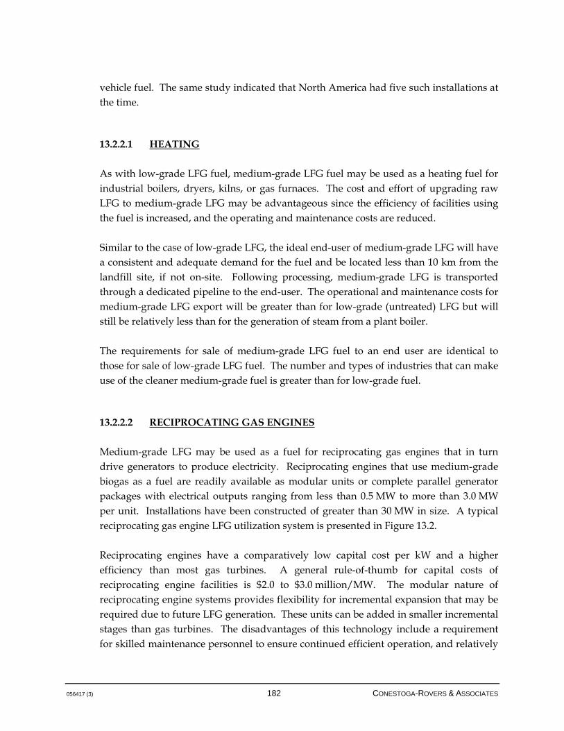
056417 (3) 182 CONESTOGA-ROVERS & ASSOCIATES
vehicle fuel. The same study indicated that North America had five such installations at the time. 13.2.2.1 HEATING
As with low-grade LFG fuel, medium-grade LFG fuel may be used as a heating fuel for industrial boilers, dryers, kilns, or gas furnaces. The cost and effort of upgrading raw LFG to medium-grade LFG may be advantageous since the efficiency of facilities using the fuel is increased, and the operating and maintenance costs are reduced. Similar to the case of low-grade LFG, the ideal end-user of medium-grade LFG will have a consistent and adequate demand for the fuel and be located less than 10 km from the landfill site, if not on-site. Following processing, medium-grade LFG is transported through a dedicated pipeline to the end-user. The operational and maintenance costs for medium-grade LFG export will be greater than for low-grade (untreated) LFG but will still be relatively less than for the generation of steam from a plant boiler. The requirements for sale of medium-grade LFG fuel to an end user are identical to those for sale of low-grade LFG fuel. The number and types of industries that can make use of the cleaner medium-grade fuel is greater than for low-grade fuel. 13.2.2.2 RECIPROCATING GAS ENGINES
Medium-grade LFG may be used as a fuel for reciprocating gas engines that in turn drive generators to produce electricity. Reciprocating engines that use medium-grade biogas as a fuel are readily available as modular units or complete parallel generator packages with electrical outputs ranging from less than 0.5 MW to more than 3.0 MW per unit. Installations have been constructed of greater than 30 MW in size. A typical reciprocating gas engine LFG utilization system is presented in Figure 13.2. Reciprocating engines have a comparatively low capital cost per kW and a higher efficiency than most gas turbines. A general rule-of-thumb for capital costs of reciprocating engine facilities is $2.0 to $3.0 million/MW. The modular nature of reciprocating engine systems provides flexibility for incremental expansion that may be required due to future LFG generation. These units can be added in smaller incremental stages than gas turbines. The disadvantages of this technology include a requirement for skilled maintenance personnel to ensure continued efficient operation, and relatively

056417 (3) 183 CONESTOGA-ROVERS & ASSOCIATES
high maintenance costs. Additional disadvantages include necessity for cooling, exhaust gases that may contain products of incomplete combustion, high lubricating oil consumption, and possible classification of the waste lubricating oil as hazardous for disposal purposes. Another benefit to using reciprocating engines is the potential to use the waste heat from the engines for a greenhouse using heat exchangers and for local space heating on the site. Technological refinements by some engine manufacturers have continuously improved the performance and durability of gas-fuelled reciprocating engines for LFG and biogas applications. These engines are specifically designed to resist corrosion and deliver higher performance from low-BTU fuels such as LFG. Critical engine components have been modified to help mitigate the affect of contaminants found in LFG on the engine. Such design improvements decrease the level of fuel pre-treatment that may be necessary and reduce unscheduled downtime, extend service intervals, and provide a more consistent power output with lower emissions.
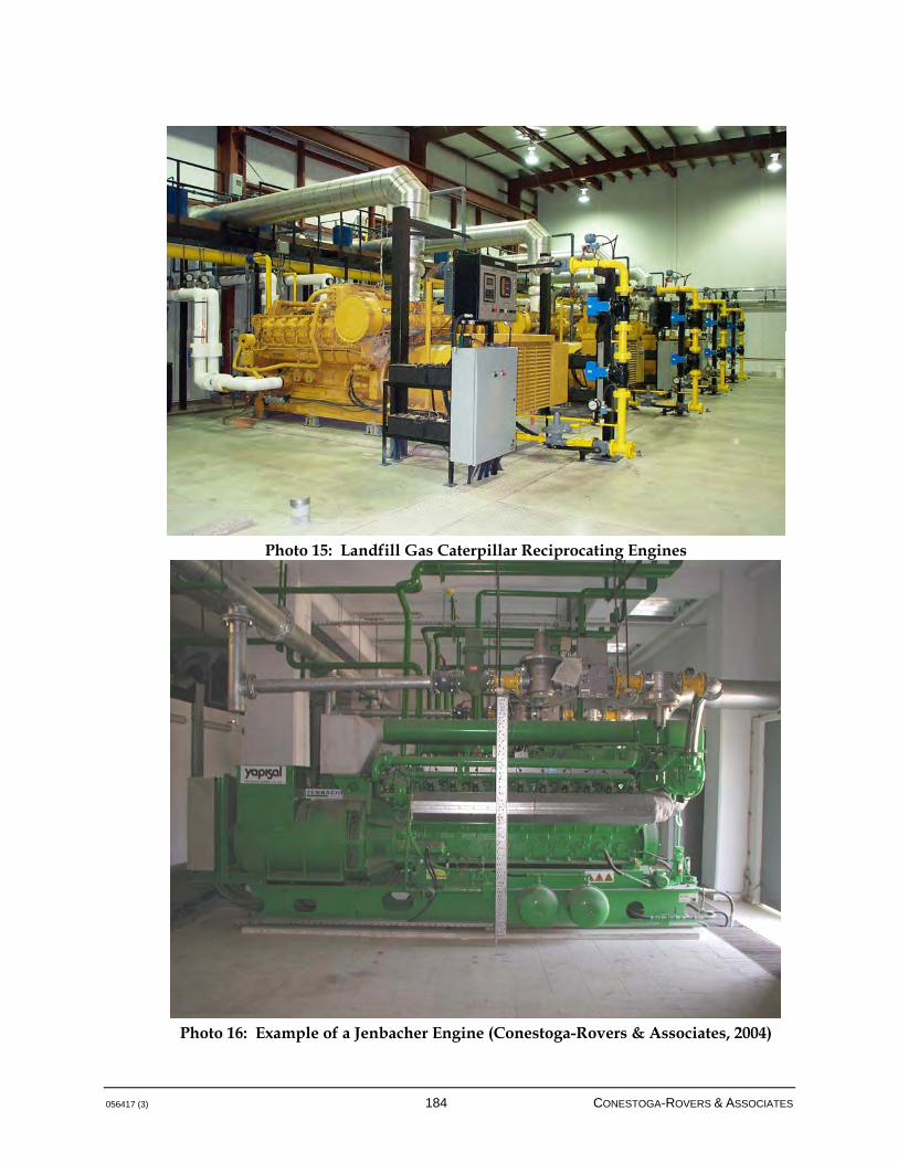
056417 (3) 184 CONESTOGA-ROVERS & ASSOCIATES
Photo 15: Landfill Gas Caterpillar Reciprocating Engines
Photo 16: Example of a Jenbacher Engine (Conestoga-Rovers & Associates, 2004)
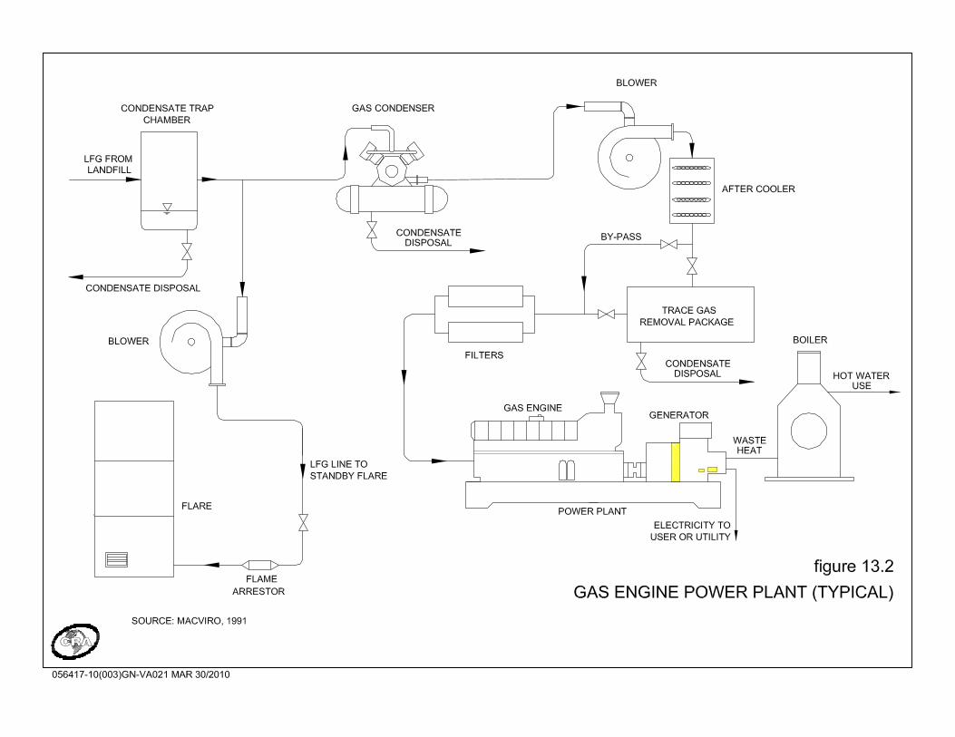

056417 (3) 186 CONESTOGA-ROVERS & ASSOCIATES
13.2.2.3 GAS TURBINES
Gas turbines work on simple, established principles, operating on rotary rather than reciprocating motion. Gas turbines basically comprise a compressor, combustor, and power turbine components. In the first stage, air is compressed and directed to the combustor for mixing with the fuel and combusted. Combustion gases are directed to the power turbine and energy is recovered through shaft horsepower. Gas turbines are available as modular and packaged systems and may have some application for sites with higher, more stable biogas generation rates. Gas turbines are generally larger than reciprocating engines with electrical outputs ranging from 1 MW to 10 MW for each unit, but also offer some flexibility in terms of modular expansion to suit changes in biogas generation, albeit at larger increments than for reciprocating engines. Gas turbines usually have a higher capital cost and somewhat lower energy conversion efficiencies compared to reciprocating engines. However, they have cleaner air emissions and fewer operational and maintenance requirements than reciprocating gas engines of equivalent size. Gas turbines can operate on lower calorific values and lower-concentration methane (13.4 MJ/m3 [360 BTU/cf] at 40 percent CH4) than reciprocating engines (14.9 MJ/m3 [400 BTU/cf] at 45 percent CH4). In addition, gas turbines also offer the flexibility to proceed directly to the combined heat and power technology, should LFG generation warrant. A few gas turbines have been successfully adapted for LFG applications. However, the compression package that must precede the turbine is the most sensitive piece of equipment for the efficient long-term reliability of the facility. Typically, the requirements for the compression stage will govern the level of biogas processing that will be necessary to ensure reasonable operating and maintenance costs for the facility. 13.2.2.4 COMBINED HEAT AND POWER SYSTEMS
Combined heat and power systems, or combined cycle, use both gas turbine(s) and steam turbine(s) together to produce electricity. This process produces a significant improvement in electrical conversion efficiency, realized by recovering and utilizing the high quality waste heat from the gas turbines in a waste heat boiler. The waste heat is redirected to a boiler that provides steam to drive a steam turbine. Use of waste heat from the gas turbine(s) reduces the volume of LFG required for the boiler.

056417 (3) 187 CONESTOGA-ROVERS & ASSOCIATES
The modular nature of the gas turbine system allows LFG developers some degree of flexibility for incremental expansion of combined-cycle systems should more LFG be produced and become available for use. This is generally controlled by the size of the steam turbines. Exhaust gases from gas turbines may contain products of incomplete combustion. Reuse of the waste heat gases improves plant air emissions. Due to the complex nature of the combined-cycle process, continuous plant supervision is required. The costs for a combined cycle facility at a suitable large site may have a lower capital cost per installed MW of electrical generating capacity due to the significant energy conversion efficiency gain that can be achieved. Combined-cycle systems can be designed to accommodate various size requirements but, due to economies of scale, are generally cost-effective for plants with greater than 10 MW output. 13.2.3 HIGH-GRADE FUEL
As previously noted, the use of high-grade fuels is common in industry. Natural gas and natural gas pre-treatment technologies are well established. However, processing of LFG to high-grade levels is a relatively new area and, in comparison to technologies that utilize low- or medium-grade biogas for electricity generation, far fewer established installations. Generally, high-grade fuel is developed only at larger sites where a large biogas flow can justify the capital investment of removing the majority of the biogas constituents, including carbon dioxide. As the economics of high-grade fuel and the costs for pre-treatment improve, the viability of this class of biogas utilization may also improve. Currently, renewed interest in this application has been demonstrated, but, technical issues aside, the economics are the main factor in viability. 13.2.3.1 PIPELINE GAS
Utilization of high quality biogas to produce pipeline quality gas has been undertaken at several landfills in the U.S. and Europe. The methane component of refined LFG is generally used as a direct substitute for natural gas and has heating value of approximately 37.3 MJ/m3 (1,000 BTU/cf). The pipeline quality gas is delivered under pressure either to the local utility or directly to customers. Therefore, the markets for this type of product are nearby natural gas utilities or industrial users. Generation of pipeline quality gas involves the removal of carbon dioxide and other gases present in

056417 (3) 188 CONESTOGA-ROVERS & ASSOCIATES
LFG, resulting in gas that is approximately 98 percent methane by volume. A typical pipeline-quality gas utilization system is presented in Figure 13.3.
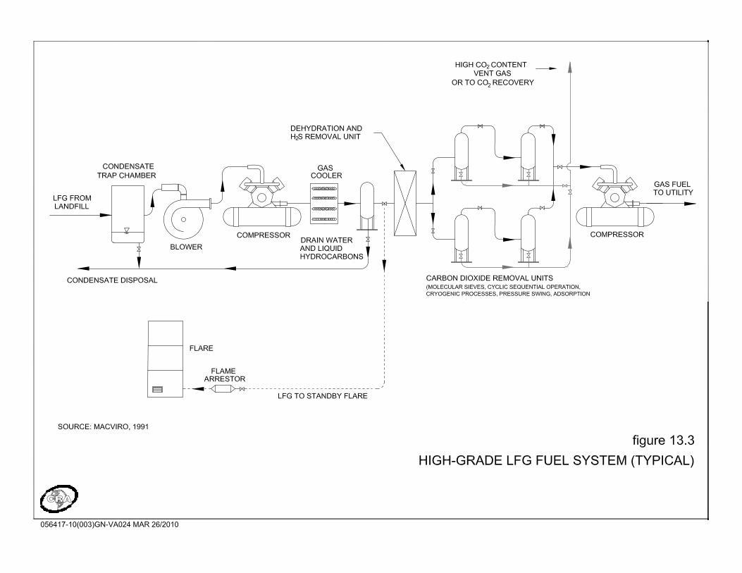

056417 (3) 190 CONESTOGA-ROVERS & ASSOCIATES
The capital costs to develop pipeline grade gas supply are governed by the gas quality standards that must be achieved. This approach must always be developed on a site-specific and project-specific basis, and it is not appropriate to suggest general cost ranges and allowances. While the potential for this utilization option is high, several factors must be investigated. First, purchasers of the purified biogas will establish quality criteria that must be met, necessitating careful attention to the pre-treatment selected and ongoing maintenance of the equipment. Generally, the range of pre-treatment required can vary according to the requested criteria. Additionally, interconnection to a natural gas piping system is not a trivial arrangement and significant costs can potentially be involved in compression and interconnection. Of note, while feed-in tariff projects have enabled the installation of electricity plants at landfills, the same type of fixed-rate, fixed-term contracts have not appeared in the North American context for pipeline gas projects. Additionally, the natural gas market has demonstrated some degree of volatility in recent years, suggesting that the revenue stability of pipeline gas projects may be suspect until such time as a feed-in tariff-type arrangement appears. 13.2.3.2 COMMERCIAL SALE OF CARBON DIOXIDE
The generation of pipeline-quality gas involves the removal of carbon dioxide and other trace gases present in the LFG. Although not a primary product of purification and generally never the prime driver for LFG cleaning, the sale of the carbon dioxide component can be a secondary revenue source if markets are available. Generation of carbon dioxide results from the separation of LFG into its major constituents and is considered to be a by-product of the generation of high-grade fuel derived from LFG. Although technically viable, no known existing or planned facilities sell carbon dioxide derived from LFG. If markets could be established, the sale of carbon dioxide could contribute to the overall viability of a project to convert LFG to pipeline-quality fuel. The largest use of carbon dioxide is in the food processing and beverage industries. The use of carbon dioxide from LFG for this use has both perceptual and liability implications that will tend to limit access to this market.
056417 (3) 191 CONESTOGA-ROVERS & ASSOCIATES
13.2.3.3 CHEMICAL PRODUCTS GENERATION
Methane and carbon dioxide, the principal components of LFG, may be used as feedstock for certain chemical products such as methanol, fertilizers, and fuel cells. Proprietary processes are available to produce methanol from biogas streams, although very limited evidence suggests that this is viable for LFG projects. Methanol can be used as an alternative fuel or fuel-additive for gasoline and diesel-powered engines, and as an alternative bleaching agent for the pulp and paper industry. The high capital costs, limited markets for products, and complexity of the process make this option a less favoured alternative. In general, the high cost of this technology makes this option worthy of consideration primarily for medium and larger sites. Compressed gas storage and subsequent use is also technically viable, although the present market conditions generally do not make it economically viable at the present time. 13.2.3.4 FUEL CELLS
Fuel cells are a relatively new technology that directly converts hydrogen to energy. Similar in principle to batteries, an electrolytic solution is used to generate an electro-chemical reaction from an influent fuel supply. As opposed to many of the other utilization options, combustion mechanisms are not included. Fuel cell systems have a higher level of energy conversion efficiency (approximately 40 percent) and lower emissions (Pacey, 1994) than other methods of electrical generation from LFG, although electrical efficiencies for reciprocating engines have now crossed the 40 percent efficiency mark, so the advantages of fuel cells may have diminished. Use of LFG for fuel cells requires the use of a high-grade fuel processor, including a fuel cell stack power transformer and cooling tower for waste heat treatment. A fuel cell-based power generation plant can be constructed using a number of individual fuel cells, making the system incremental and allowing for expansion to coincide with the fuel resource. Like other high-grade LFG applications, fuel cells require extensive pre-treatment. Hydrogen sulphide and halogenated hydrocarbons can cause problems for fuel cells at low levels (Reinhart, 1994). Currently, the price of this technology is much higher than other utilization technologies because fuel cells are not produced in commercial quantities. As the number of cells
056417 (3) 192 CONESTOGA-ROVERS & ASSOCIATES
produced increases, it is expected that the price will drop, increasing the economic viability of fuel cell-based utilization projects. 13.2.3.5 FUEL FOR VEHICLES
Compressed natural gas (CNG) and liquefied natural gas (LNG), produced through proprietary processes, have been used to fuel vehicles as part of a demonstration project at the Puente Hills Landfill in California. In order to utilize the gas, it must first be treated to remove impurities and boost its fuel value before it is compressed. The quality of vehicle-grade fuels must be strictly maintained to meet the requirements of the utilization technology. This technology is currently being practiced at the full-scale level at some sites and has moved beyond the pilot level. Advantages of this application include a reduction in fossil fuel consumption and local ozone pollution. However, significant costs are associated with the retrofitting of vehicles to accept this type of fuel and the cost of building fuelling stations. These technologies are generally proprietary in nature and project-specific costing is necessary to assess the application of this technology to a site. One very clear benefit of this technology is the potential carbon emission reduction benefits. Use of LFG to replace natural gas and electricity creates a relatively modest GHG emission reduction via the displacement of these fuels, especially since they are generally quite "clean"; in BC, electricity generation is especially clean from a carbon footprint standpoint. However, use of LFG in vehicle applications to replace the use of, for example, diesel fuel, provides a much greater carbon benefit. This aspect needs to be weighed against the price for fossil fuels and the overall costs associated with upgrading vehicles to receive this fuel supply. 13.3 UTILIZATION SELECTION FACTORS
The selected option for utilization is dependant on a number of factors, including energy or product sales prices, capital and operating costs, and proximity to infrastructure such as electricity or natural gas transmission. The vast majority of utilization alternatives are associated with electricity generation, as the basic equipment for this application is readily available and the economics are favorable. Electricity generation can be achieved with low- and medium-grade LFG using a variety of technologies and with minimal pre-treatment requirements. For high-grade applications, such as the

056417 (3) 193 CONESTOGA-ROVERS & ASSOCIATES
generation of natural gas or fuel for fuel cells, pre-treatment requirements increase considerably, as do the costs for this level of processing. Currently, a limited number of installations perform this level of pre-treatment, but as energy sales prices increase and the technology matures from a cost and technical standpoint, it is expected that interest in this area will increase. Figure 13.4 provides a flow chart for a typical LFG utilization development decision process.

056417 (3) 195 CONESTOGA-ROVERS & ASSOCIATES
All relevant factors must be carefully considered to select the optimal utilization option for the application. One particular factor that must be considered is the presence of trace compounds in the biogas, such as those mentioned above, which may affect either the selection of the utilization technology or mandate a level of pre-treatment to remove some or all of the trace compounds. Generally, the effect of different trace compounds in LFG on utilization options is well known; compounds of concern include free moisture, moisture in vapour form, particulates, hydrogen sulphide, siloxanes, halogenated carbon compounds, and, where natural gas quality is required, carbon dioxide. All of these compounds can be tested for using available techniques, and laboratories are generally able to analyze for the required parameters. The following provides a list of basic parameters that should be explored when evaluating the economic and technical feasibility of LFG utilization. LFG Availability and Scope of Project The overall viability of a LFG utilization project is economically-driven. For smaller landfill sites, the economics of LFG utilization are generally more challenging, as some of the basic infrastructure costs are independent of project size. Further, utilization technologies for smaller landfills are limited. Reciprocating engines are generally a minimum of 0.5 MW; while microturbines are available at smaller sizes, the track record of this technology is limited and costs are relatively high. One potential means of improving the economic viability of smaller projects is a feed-in tariff that considers the relative differences in project size and the required revenue stream to improve viability. In Ontario, the so-called Feed-In Tariff program (Available at http://fit.powerauthority.on.ca/) is the clearest example of a system that has been in existence in Europe for quite some time. Under this program, the price structure shown in Table 13.2 is offered for biogas utilization projects. In BC, BC Hydro has committed to sourcing 90 percent of new supply from clean energy sources and has developed a Standing Offer Program for clean energy projects between 0.5 and 10 MW. As part of a power purchase agreement, BC Hydro will retain the green attributes (in this case carbon credits) developed as part of a project. The program offers similar pricing for all green energy projects and is not specifically targeted to LFG utilization (BC Hydro, 2009). Terasen Gas is currently exploring biogas as an alternative energy source through developing gas purchase agreements for LFG (Terasen Gas, 2010).
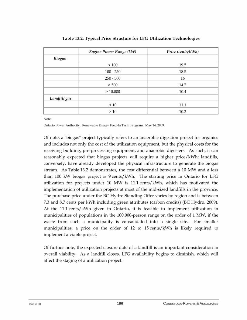
056417 (3) 196 CONESTOGA-ROVERS & ASSOCIATES
Table 13.2: Typical Price Structure for LFG Utilization Technologies
Engine Power Range (kW) Price (cents/kWh)
Biogas
< 100 19.5
100 - 250 18.5
250 - 500 16
> 500 14.7
> 10,000 10.4
Landfill gas
< 10 11.1
> 10 10.3
Note:
Ontario Power Authority. Renewable Energy Feed-In Tariff Program. May 14, 2009.
Of note, a "biogas" project typically refers to an anaerobic digestion project for organics and includes not only the cost of the utilization equipment, but the physical costs for the receiving building, pre-processing equipment, and anaerobic digesters. As such, it can reasonably expected that biogas projects will require a higher price/kWh; landfills, conversely, have already developed the physical infrastructure to generate the biogas stream. As Table 13.2 demonstrates, the cost differential between a 10 MW and a less than 100 kW biogas project is 9 cents/kWh. The starting price in Ontario for LFG utilization for projects under 10 MW is 11.1 cents/kWh, which has motivated the implementation of utilization projects at most of the mid-sized landfills in the province. The purchase price under the BC Hydro Standing Offer varies by region and is between 7.3 and 8.7 cents per kWh including green attributes (carbon credits) (BC Hydro, 2009). At the 11.1 cents/kWh given in Ontario, it is feasible to implement utilization in municipalities of populations in the 100,000-person range on the order of 1 MW, if the waste from such a municipality is consolidated into a single site. For smaller municipalities, a price on the order of 12 to 15 cents/kWh is likely required to implement a viable project. Of further note, the expected closure date of a landfill is an important consideration in overall viability. As a landfill closes, LFG availability begins to diminish, which will affect the staging of a utilization project.
056417 (3) 197 CONESTOGA-ROVERS & ASSOCIATES
Energy Sales Prices Electricity prices may be fixed-term, fixed-price contracts that offer greater revenue certainty but that generally do not include price escalation consistent with inflationary costs related to plant maintenance and operation. Natural gas prices can be volatile and generally do not offer fixed-price contracts on the feed-in tariff model, although long-term contracts may be individually negotiated and Terasen Gas is actively seeking to explore biogas projects. Capital and Operating Costs Considerable variation exists in the type of utilization projects, and the cost basis is generally best understood for projects that are already implemented. For example, the cost for reciprocating engine plants generally runs between $2.0 and 3.0 million/MW installed; note that, as a rule of thumb based on current electrical conversion efficiencies for these engines, approximately 1.8 kW gross are produced for every m3/hr of LFG supplied at 50 percent methane composition. Few utilization options exist of any scale that do not require dedicated operations staff and maintenance of the physical infrastructure. A reciprocating engine plant, for example, generally requires somewhere on the order of 2 cents/kWh produced simply to maintain the engines, without consideration for operating the plant or paying for an operator. Note that parasitic losses (self-consumed electricity) must also be taken into account, as they will affect the total exported electricity. Parasitic losses for reciprocating engine plants include energy spent on gas compressors, jacket water pumps, lube oil pumps, radiator fans, generator fans, station transformers, and other station auxiliaries. Although uptime of reciprocating engine plants should be above 95 percent, estimated downtime should be included in the overall economic analysis of the project. The capital and operating cost basis varies quite significantly when moving towards high-grade fuel options. Technical Feasibility Most of the utilization projects in North America, and Canada specifically, produce electricity, as the technology is established and the requirements for pre-treatment are understood. While projects intended to, for example, produce fuel for vehicles, are gaining in interest, the technical track record for these projects is relatively sparse. Project developers should assess their own risk tolerance when investigating LFG utilization projects that have few demonstrated, successful applications. Pre-treatment is another important technical and cost item. High-grade fuel applications require additional costs for pre-treatment, and some of the available pre-treatment technologies

056417 (3) 198 CONESTOGA-ROVERS & ASSOCIATES
have limited track record. This is a specific risk issue, as, for example, pipeline grade applications set very specific limits on contaminant levels that must be achieved. GHG Emission Reductions Two basic greenhouse gas emission reductions are associated with LFG utilization. The first is the direct combustion of the methane component of LFG and the associated reduction of methane's global warming potential. This factor is essentially equal for all LFG utilization systems that include combustion, and is generally the primary greenhouse gas emission reduction. The Pacific Carbon Trust is actively seeking to purchase carbon offsets to meet the provincial government's goal of carbon neutral operations including the purchase of carbon credits resulting from the combustion of LFG. The Pacific Carbon Trust is seeking to purchase 1,000,000 tonnes of carbon dioxide equivalent annually at a price of between $10 and $20 per tonne of carbon dioxide equivalent (Pacific Carbon Trust, 2010). The second element is the offset of other energy types, whose value varies widely with the type of utilization system. For example, offsetting electricity in BC provides relatively low numbers of emission reductions given the predominance of hydroelectric power in the province. In BC, the electrical offset emission reductions from a LFG-to-electricity project are roughly in the range of 5 to 10 percent of the total methane-related emission reductions. Offsetting natural gas is also a relatively small item in terms of emission reductions. The greatest potential for offsets comes from the generation of vehicle fuel, which will presumably offset diesel fuel emissions. As direct combustion of diesel fuel is a significant emission source, replacement of this fuel with a renewable energy can potentially yield significant emission reductions for the same volume of LFG. The importance of GHG emissions must be explored against the potential economic benefits of selling offsets, the need to meet regulatory compliance, and issues surrounding corporate and municipal sustainability. Regulatory Compliance In the Canadian context, no provinces has a specific requirement to implement utilization, although approvals are still required for the landfill works and air emissions associated with these projects. The European Union's Landfill Directive, on the other hand, requires that any LFG captured at landfills be utilized if possible.

056417 (3) 199 CONESTOGA-ROVERS & ASSOCIATES
Greenhouse gas credits are highly dependent on additionality (ie. demonstrated value above some common practice or requirement). In terms of utilization, the greenhouse gas credits available from production of, for example, green electricity, may be viable for certification even as BC regulations begin to enforce LFG collection. The specific viability of this commodity must always be addressed by examining the eligibility requirements of the pertinent GHG protocol or methodology.
056417 (3) 200 CONESTOGA-ROVERS & ASSOCIATES
REFERENCES
Air Toxics Ltd, Guide to Air Sampling and Analysis, 2007, Available at: http://www.airtoxics.com/literature/AirToxicsLtdSamplingGuide.pdf. BC Hydro. Standing Offer Program Rules. 2009. Available at: http://www.bchydro.com. British Columbia Ministry of Environment (BC MOE). Landfill Gas Management Regulation. December 2008. Canadian Standards Association, Canada Gas Association (CAN/CGA). Code For Digester Gas and Landfill Gas Installations – CAN/CGA-B105-M93. 2007. Christensen, Thomas H., and Peter Kjeldsen. Basic Biochemical Processes in Landfills in Sanitary Landfilling : Process, Technology and Environmental Impacted. Thomas H. Chistensen, Raffaello Cossu, and Rainer Stegmann (Academic Press, New York, 1989) p.29. California Integrated Waste Management Board (CIWM). Control of gaseous emissions from municipal solid waste landfills - Rule 1150.1. 2000. Capstone Turbine Corp. Capstone Microturbine Fact Sheet. Chatsworth: Capstone Turbine Corp., 2002. Conestoga-Rovers & Associates (CRA). Waterloo Sanitary Landfill Site Phases I and 2 Landfill Gas Action Plan. Report to the Region of Waterloo, 1994. Conestoga-Rovers & Associates (CRA). Prepared for Environment Canada, Waste Treatment Division, Hazardous Waste Branch, Guidance Document for Landfill Gas Management, 1996. (Environment Canada, 1996). Conestoga-Rovers & Associates (for the Energy Sector Management Assistance Programme), Handbook for the Preparation of Landfill Gas to Energy Projects in Latin America and the Caribbean, (The World Bank, 2004). Conestoga-Rovers & Associates, Inspection and Maintenance Plan and Operations Manual for the Landfill Gas Collection System at the Saria Landfill, (CRA, 2007).
056417 (3) 201 CONESTOGA-ROVERS & ASSOCIATES
Conestoga-Rovers & Associates (for Natural Resources Canada), Biogas Treatment State-of-the-Art Review, (CRA, 2007). Conestoga-Rovers & Associates (for the British Columbia Ministry of Environment), Landfill Gas Generation Assessment Procedure Guidance Report, (CRA, 2009). Conestoga-Rovers & Associates (for the South West Solid Waste Commission), Feasibility Study of Landfill Gas (LFG) Utilization Options for the Hemlock Knoll Waste Management Facility, (CRA, 2009). Environment Canada. Characterization of Greenhouse Gases and Volatile Organic Compound from Vented Landfill Gases. August 1995. Environment Canada. National Inventory Report, Greenhouse Gas Sources and Sinks in Canada, 1990-2007. April 2009. Environment Canada. National Inventory Report, Greenhouse Gas Sources and Sinks in Canada, 1990-2008. April 2010. Farguhar, O. and Rovers, F.A. Gas Production During Refuse Decomposition, Water, Air and Soil Pollution, 2(10), pp. 483-499, 1973. Golder Associates. Methane Collection and Oxidation Efficiency Assessment Cache Creek Landfill, BC. October 2009. Government of Canada. Canada's National Report on Climate Change. Cat. EN21-125/1994E, ISBN:0-662-21411-0, 1994. Government of Canada. Canada's Kyoto Commitments. December 2009. Available at: http://www.climatechange.gc.ca/default.asp?lang=En&n=9AED6229-1. Ham, Robert K., and Morton A. Barlaz. Measurement and Prediction of Landfill Gas Quality and Quantity in Sanitary Landfilling: Process, Technology and Environmental Impacted. Thomas H. Chistensen, Raffaello Cossu, and Rainer Stegmann (Academic Press, New York, 1989) p.155-158. Intergovernmental Panel on Climate Change (IPCC). Fourth Assessment Report: Climate Change 2007 (AR4). Working Group I. Available at: http://www.ipcc.ch/publications_and_data/ar4/wg1/en/contents.html.
056417 (3) 202 CONESTOGA-ROVERS & ASSOCIATES
LiveSmart BC. 2008. Available at: http://www.livesmartbc.ca/ Maxxam Analytics. Soil Vapour Sampling Using Summa Canisters. 2008. Available at: http://www.sabcs.chem.uvic.ca/A%20Soil%20Vapour%20ForumMaxxam-Summa.pdf. McBean, E.A., F.A. Rovers, and G.J. Farquhar. Solid Waste Landfill Engineering and Design, New Jersey: Prentice Hall, 1995. Mostardi, T., Banach, S. and Leedom, I., Control of Hazardous Air Pollutants Landfill Gas Testing, Wisconsin Administrative Code cli. NR445, September 1991. Pacey, I., Doom, M. and Thorneloc, S., Landfill Gas Energy Utilization: Technical and Non-Technical Considerations. Presented at SWANA's 17th Annual Landfill Gas Symposium, Long Beach, California, 1994. Pacific Carbon Trust. Sell Offsets to PCT. March 31, 2010. Available at: www.pacificcarbontrust.com. Reinhart, D.R. 1994. Beneficial Use of LFG. University of Central Florida, Report #94-7, September 30, 1994. Scottish Environment Protection Agency (SEPA). Guidance on the Management of Landfill Gas. September 2004. South-Coast Air Quality Management District (SCAQMD). Control of gaseous emissions from municipal solid waste landfills, Rule 1150.1, 2000. Available at: http://www.aqmd.gov/rules/reg/reg11/r1150-1.pdf. Terasen Inc. Biogas. 2010. Available at: www.terasen.com U.S. Department of Energy, Electricity Delivery & Energy Reliability. Microturbines. 2006. Available at: http://www.eere.energy.gov/de/microturbines/tech_basics.html. United States Environmental Protection Agency (USEPA), Compilation of Air Pollutant Emission Factors, Volume 1: Stationary and Area Sources, Report AP.-42, 1993.
056417 (3) 203 CONESTOGA-ROVERS & ASSOCIATES
United States Environmental Protection Agency (USEPA), Part 60 - Standards of Performance for New Stationary Sources (NSPS) - Subpart WWW - Standards of Performance for Municipal Solid Waste Landfills. March 1996. United States Environmental Protection Agency (USEPA), Global Mitigation of Non-CO2 Greenhouse Gases. June 2006. United States Environmental Protection Agency (USEPA), Air Emissions from Municipal Solid Waste Landfills – Background Information For Final Standards and Guidelines. December 1995. United States Environmental Protection Agency (USEPA), Landfill Methane Outreach Program: Landfill Gas. 2010. Available at: http://www.epa.gov/lmop/faq/landfill-gas.html. Wellinger, A. and A. Lindberg. Biogas Upgrading and Utilization. IEA Bioenergy Task 24: Energy from biological conversion of organic waste. 2001. Available at: http://www.recyclenow.org/Report_IEA_Bioenergy_1MB.pdf. Wheless, E. and J. Pierce. Siloxanes in Landfill and Digester Gas Update, SWANA 27th LFG Conference, March 22-25, 2004. Yesiller, N., Hanson, J.L., 2008. Measurement and Estimation of Landfill Surface Gas Emissions. California Polytechnic State University, December 2008.

056417 (03)
APPENDICES
056417 (03)
APPENDIX A
LANDFILL GAS MANAGEMENT FACILITIES
DESIGN PLAN
LANDFILL GAS MANAGEMENT FACILITIES DESIGN PLAN FOR THE [NAME] LANDFILL
Prepared For: British Columbia Ministry of Environment
Prepared By: [Municipality/Corporation]
APRIL 2010

056417 (3) i CONESTOGA-ROVERS & ASSOCIATES
INSTRUCTIONS FOR USE The following template has been developed to outline the format and content required for the landfill gas (LFG) management facilities design plan (report) required under the British Columbia Landfill Gas Management Regulation (Regulation), approved and ordered on December 8, 2008. If all information outlined in the following template is provided completely and accurately, all content requirements of Section 7 "Landfill Gas Management Facilities Design Plan" of the Regulation will be satisfied. However, the user must consult the requirements described in Section 7(3) of the Regulation to ensure the report is submitted on the schedule required by the director of the British Columbia Ministry of Environment (MOE). The report template has been colour coded to simplify the use of the template. The colours differentiate text that is part of the template (to be included in the design report), requirements of the Regulation, and information as described in the Landfill Gas Management Facilities Design Guidelines. The colour coding system is as follows:
Text Colour Description
Black Text Black text should be included in the final report.
Blue Text Blue text is used to describe requirements presented in the Regulation. Blue text should be replaced with the required information and should not be included in the final report.
Brown Text Brown text is used to describe information in the Guidelines. Brown text should be replaced with site-specific information and should not be included in the final report.
Blue and brown text should not be included in the final version of the LFG management facilities design plan produced using this template. The coloured text is provided to describe the required information and should be replaced by the user to complete the required design plan. The user of this template should convert all text in the final report to black prior to submission of the report to the director.

056417 (3) CONESTOGA-ROVERS & ASSOCIATES
TABLE OF CONTENTS Page
1.0 INTRODUCTION .............................................................................................................. A-1
2.0 SITE CONDITIONS AND DESIGN OBJECTIVES........................................................ A-1
3.0 LANDFILL GAS MANAGEMENT FACILITIES DESIGN .......................................... A-1 3.1 COLLECTION FIELD.................................................................................... A-1 3.1.1 HORIZONTAL COLLECTION TRENCH DESIGN.................................. A-1 3.1.2 VERTICAL EXTRACTION WELL DESIGN............................................... A-2 3.1.3 COLLECTION FIELD PIPING DESIGN..................................................... A-2 3.1.4 LEACHATE COLLECTION SYSTEM CONNECTIONS.......................... A-3 3.2 CONDENSATE MANAGEMENT............................................................... A-3 3.3 LANDFILL GAS EXTRACTION PLANT ................................................... A-4 3.4 METERING EQUIPMENT ............................................................................ A-4 3.5 LFG COMBUSTION/UTILIZATION SYSTEM ......................................... A-4 3.5.1 FLARING......................................................................................................... A-5 3.5.2 BENEFICIAL UTILIZATION EQUIPMENT.............................................. A-5 4.0 SYSTEM INSTALLATION, OPERATION, AND MAINTENANCE ...... A-5
5.0 SYSTEM OPTIMIZATION ............................................................................................... A-6
6.0 ADDITIONAL INFORMATION ..................................................................................... A-6
056417 (3) CONESTOGA-ROVERS & ASSOCIATES
LIST OF FIGURES (Following Text)
FIGURE 1 EXISTING SITE CONDITIONS FIGURE 2 PROPOSED LFG MANAGEMENT SYSTEM SCHEMATIC
LIST OF DRAWINGS (Following Text)
DRAWING 1 PROPOSED LFG MANAGEMENT SYSTEM DRAWING 2 PROPOSED LFG MANAGEMENT SYSTEM DETAILS DRAWING 3 HORIZONTAL COLLECTION TRENCH AND LFG HEADER PIPE
DETAILS DRAWING 4 VERTICAL EXTRACTION WELL DETAILS DRAWING 5 LFG HEADER PLAN AND PROFILE DRAWINGS (may require more than one drawing) DRAWING 6 VALVE CHAMBER DETAILS DRAWING 7 LEACHATE COLLECTION SYSTEM CONNECTION DETAILS DRAWING 8 CONDENSATE MANAGEMENT SYSTEM DETAILS DRAWING 9 CONDENSATE KNOCKOUT DETAILS
LIST OF APPENDICES APPENDIX A FLARE SPECIFICATION DRAWINGS (FROM MANUFACTURER) (if available) APPENDIX B UTILIZATION EQUIPMENT SPECIFICATION DRAWINGS (if available)

056417 (3) A-1 CONESTOGA-ROVERS & ASSOCIATES
1.0 INTRODUCTION
This report has been prepared in accordance with the Landfill Gas Management Facilities Design Guidelines, prepared for the British Columbia Ministry of Environment (MOE) by [Municipality/Corporation], dated February 2010, and in accordance with the requirements of the British Columbia Ministry of Environment's Landfill Gas Management Regulation (Regulation), approved and ordered on December 8, 2008. This report has been prepared by a qualified professional, and meets the requirements of Section 7(2) of the Regulation. Note that a LFG management facilities design plan is also required to be submitted for landfills with a LFG management system currently installed. This template can be altered as required in this scenario. As per the Regulation, if a LFG management facilities design plant exists for a landfill with a LFG management system in place, a qualified professional must certify in writing that the current system is complying with the performance and design standards and objectives outline in the Guideline. Further to the Regulation, if any of the standards or objectives are not currently being met, future plans to attempt to reach these requirements must be provided in writing by a qualified professional. These future plans may be outlined within this design plan template.
2.0 SITE CONDITIONS AND DESIGN OBJECTIVES
This section should include a general description of the site, including opening and anticipated closure year, amount of waste in place, landfill area, waste handling procedures, waste covering, landfill cell construction, and future filling procedure. Refer to existing site conditions drawing (Figure 1) and proposed LFG management system schematic (Figure 2). This section should also include a description of the design objectives for the design of a LFG collection system for the landfill Site including: • LFG generation model results from the landfill gas generation assessment report
• On-site health and safety safeguards as they relate to landfill gas migration and control
• Discussion of depth to landfill liner (if applicable)
• Discussion of existing leachate collection system and leachate levels in the landfill (if applicable/known)
056417 (3) A-2 CONESTOGA-ROVERS & ASSOCIATES
3.0 LANDFILL GAS MANAGEMENT FACILITIES DESIGN
The following section presents the information required under Sections 7(2)(a) and 7(2)(d) of the Regulation. 3.1 COLLECTION FIELD
This section should include a description of the planned methods, management practices and processes for the design of a LFG collection field for the landfill site. Refer to Drawing 1 which provides a plan view of the proposed LFG management system, with the collection field design (including vertical extraction wells, horizontal collection trenches, all piping, locations of condensate management components, and the locations of the LFG extraction plant and utilization system (if applicable). Refer to Drawing 2 which includes all the detail as provided on Drawing 1 and the inclusion of pipe sizing, materials and slope direction, and references to other drawings for details of each component. 3.1.1 HORIZONTAL COLLECTION TRENCH DESIGN
This section should include a description of the horizontal collection trench design for LFG management at the landfill site (if applicable), including: • Trench depth
• Trench spacing
• Trench materials
• Control valves
• Horizontal cleanouts design (if applicable)
• Material sizing
• Monitoring points and equipment
• Installation plan
• Discussion and reference to Drawings 2, 3 and 6.
Note that many of these requirements may be met by providing these details on the drawings. Details may include typical horizontal collection trench connection, horizontal collection pipe perforation design, horizontal collection trench cross section,
056417 (3) A-3 CONESTOGA-ROVERS & ASSOCIATES
typical horizontal collection trench valve chamber detail, typical valve chamber connection, and typical monitoring port.
3.1.2 VERTICAL EXTRACTION WELL DESIGN
This section should include a description of the vertical extraction well design for LFG management at the landfill site (if applicable), including: • Well depth, including clearance above the landfill liner, leachate collection system or
granular drainage layer (as applicable)
• Well spacing/density
• Well diameter
• Well pipe materials
• Control vales
• Other installation materials
• Material sizing
• Monitoring ports and equipment
• Installation plan
• Discussion and reference to Drawings 2 and 4
Note that many of these requirements may be met by providing these details on the drawings. Details may include typical vertical extraction well, typical monitoring port, and typical chamber entry and protective chamber cover (if chambers are included in the design).
3.1.3 COLLECTION FIELD PIPING DESIGN
This section should include a description of the collection piping for LFG management at the landfill site, including: • Lateral, subheader and header pipe sizing
• Pipe materials
• Pipe slopes
• Control valves
• Monitoring ports and equipment
• Installation plan
• Discussion and reference to Drawings 2 through 5
056417 (3) A-4 CONESTOGA-ROVERS & ASSOCIATES
Note that many of these requirements may be met by providing these details on the drawings. Details may include typical lateral connection to subheader, typical LFG header trench, typical subheader/lateral trench, and conensate forcemain trench to leachate collection system (if applicable).
3.1.4 LEACHATE COLLECTION SYSTEM CONNECTIONS
Only if applicable to the LFG management facilities design, this section should include a description of the leachate collection system connections to the LFG management system at the landfill site, including: • Connection/access points
• Leachate management plan
• Monitoring locations and equipment
• Discussion and reference to Drawing 2, showing leachate collection system connection locations
• Discussion and reference to Drawing 7
Note that many of these requirements may be met by providing these details on the drawings. 3.2 CONDENSATE MANAGEMENT
This section should include a description of the condensate management system for LFG management at the landfill site, including: • Condensate trap chambers design and locations
• Condensate pump station design and locations
• Condensate management plan
• Monitoring plan
• Discussion and reference to Drawing 2, showing condensate management locations
• Discussion and reference to Drawing 8
Note that many of these requirements may be met by providing these details on the drawings. A detail that may be included is a typical condensate trap.
056417 (3) A-5 CONESTOGA-ROVERS & ASSOCIATES
3.3 LANDFILL GAS EXTRACTION PLANT
This section should include a description of the planned methods, management practices and processes for the design of a LFG extraction plant for the landfill site, including: • Process control systems
• Extraction blowers
• Condensate removal
• Piping and valves
• Discussion and reference to Figure 2 and Drawings 2 and 9
Note that many of these requirements may be met by providing these details on an additional drawing not outlined within this template. 3.4 METERING EQUIPMENT
This section should include a description of the planned methods, management practices and processes for the design of metering equipment for the landfill site. • Flow meter equipment specifications
• Analyzer equipment specifications
• Data collection and interpretation system specifications (i.e. datalogger)
• Equipment installation locations
Note that many of these requirements may be met by providing these details on an additional drawing not outlined within this template. 3.5 LFG COMBUSTION/UTILIZATION SYSTEM
This section should include a description of the planned methods, management practices and processes for the design of LFG combustion for the landfill site.
056417 (3) A-6 CONESTOGA-ROVERS & ASSOCIATES
Discuss the location of the LFG combustion and/or utilization system and reference Drawing 2, which shall include the LFG combustion and/or utilization system location . 3.5.1 FLARING
This section should include a description of the LFG flaring system for LFG control system at the landfill site, including: • Type and design of flare (refer to Appendix A)
• LFG maximum flow rate and turn down ratio of flare
• Design combustion temperature and retention time
• Destruction efficiency of non-methane hydrocarbons (NMHC's)
• Operational control systems such as temperature and combustion air control, flame failure detection, automatic ignition system, flame arrester, and any additional shutdown and safe operation controls
3.5.2 LFG UTILIZATION EQUIPMENT
This section should include a description of the LFG utilization system for the LFG management system at the landfill site, including: • LFG pretreatment
• Capacity of utilization system compared to estimated LFG generation rate
• Utilization application technology
• Discussion of utilization system layout with respect to the extraction plant with reference to Figure 2 and Drawing 2 (additional drawing may be required)
• Equipment specification drawings (to be included in Appendix B of the report)
• Energy application
4.0 SYSTEM INSTALLATION, OPERATION, AND MAINTENANCE
The following section presents the information required under Section 7(2)(b) of the Regulation.
056417 (3) A-7 CONESTOGA-ROVERS & ASSOCIATES
This section should include a description of installation, operation, and maintenance procedures of LFG management facilities at the landfill site, including: • Installation schedule
• Contingency plan for the scheduled or emergency disruption, maintenance, or replacement of system components
• Temporary shutdown procedures
5.0 SYSTEM OPTIMIZATION
The following section presents the information required under Sections 7(2)(c) of the Regulation. This section should include recommendations for optimizing LFG management at the landfill site including the integration of the LFG management system with landfill operations. Refer to the Guideline for best management practice and options for improving LFG management systems.
6.0 ADDITIONAL INFORMATION
The following section presents the information required under Sections 7(2)(e) of the Regulation. This section should include any additional information requested in writing by the director (if applicable).
056417 (3) A-8 CONESTOGA-ROVERS & ASSOCIATES
Prepared by: Name and Signature Certified/Approved by: Name; Signature or Stamp (Report must be certified and approved by a qualified professional) This signature page fulfills the requirements of Section 7(2)(f) of the Regulation.
056417 (03)
APPENDIX B
LANDFILL GAS COLLECTION EFFICIENCY ESTIMATION
SAMPLE CALCULATIONS

056417 (3)
B-1
LANDFILL GAS COLLECTION EFFICIENCY ESTIMATION SAMPLE CALCULATIONS
The collection efficiency of a landfill gas collection system is calculated using the following equation: Where:
CE = the collection efficiency expressed as a percentage (%) Qc = the normalized average collected flow rate of LFG in the given calendar year
(m3/hr) Qp = the estimated generated LFG flow rate in the given calendar year (m3/hr) which
shall be calculated according to the BC MOE's LFG Generation Estimation Tool for Annual Reporting.
Note that oxidation of LFG through the landfill cover will not be included in the calculation of LFG management system collection efficiency. The following pages outline sample calculations for determining the collection efficiency of a landfill gas collection system.
CE = Qc * 100% Qp
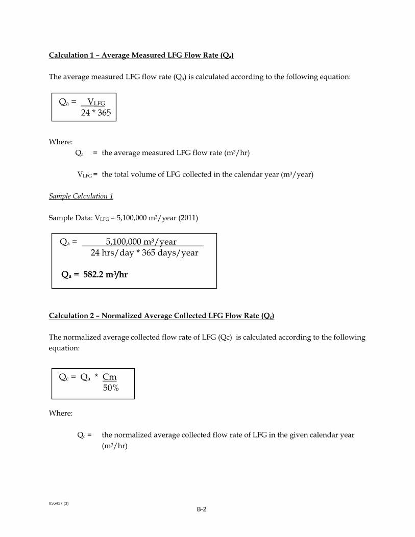
056417 (3)
B-2
Calculation 1 – Average Measured LFG Flow Rate (Qa) The average measured LFG flow rate (Qa) is calculated according to the following equation:
Where:
Qa = the average measured LFG flow rate (m3/hr) VLFG = the total volume of LFG collected in the calendar year (m3/year)
Sample Calculation 1 Sample Data: VLFG = 5,100,000 m3/year (2011)
Calculation 2 – Normalized Average Collected LFG Flow Rate (Qc) The normalized average collected flow rate of LFG (Qc) is calculated according to the following equation: Where:
Qc = the normalized average collected flow rate of LFG in the given calendar year (m3/hr)
Qa = VLFG 24 * 365
Qa = 5,100,000 m3/year 24 hrs/day * 365 days/year
Qa = 582.2 m3/hr
Qc = Qa * Cm 50%

056417 (3)
B-3
Cm = the yearly average methane concentration measured during LFG management system uptime at a central collection point near the blower or combustion/utilization device of the LFG management system expressed as a percentage (%)
Sample Calculation 2 Sample Data: Qa = 582.2 m3/hr (from Calculation 1)
Cm = 55% (2011)
Calculation 3 – LFG System Collection Efficiency (CE) As stated above, LFG system collection efficiency is calculated according to the following equation:
Where:
CE = the collection efficiency expressed as a percentage (%) Qc = the normalized average collected flow rate of LFG in the given calendar year
(m3/hr) Qp = the estimated generated LFG flow rate in the given calendar year (m3/hr) which
shall be calculated according to the BC MOE's LFG Generation Estimation Tool for Annual Reporting
Sample Data: Qp = 850 (m3/hr) for 2011.
The final collection efficiency of the landfill gas collection system is estimated to be 75.3%.
CE = Qc * 100% Qp
Qc = 582.2 m3/hr * 55% 50% Qc = 640.4 (m3/hr)
CE = 640.4 * 100% 850 CE = 75.3%
Related Documents