Design for Design for Stamping Stamping Terry Sizemore Terry Sizemore University of Detroit- University of Detroit- Mercy Mercy MPD Cohort 5 MPD Cohort 5

Design for Stamping Terry Sizemore University of Detroit-Mercy MPD Cohort 5.
Dec 21, 2015
Welcome message from author
This document is posted to help you gain knowledge. Please leave a comment to let me know what you think about it! Share it to your friends and learn new things together.
Transcript

Design for Design for StampingStamping
Terry SizemoreTerry Sizemore
University of Detroit-MercyUniversity of Detroit-Mercy
MPD Cohort 5MPD Cohort 5

ReferencesReferences
Eary and Reed: Eary and Reed: Techniques of Techniques of Pressworking Sheet Metal, 2Pressworking Sheet Metal, 2ndnd ed. ed. Prentice Prentice HallHall
Boothroyd, Dewhurst, Knight: Boothroyd, Dewhurst, Knight: Product Product Design for Manufacture and Assembly, 2Design for Manufacture and Assembly, 2ndnd ed.ed. Marcel Decker Marcel Decker
Brallia: Brallia: Design for Manufacturability Design for Manufacturability Handbook, 2Handbook, 2ndnd ed. ed., McGraw Hill, McGraw Hill
Sizemore: EMU MFG 316 Lecture NotesSizemore: EMU MFG 316 Lecture Notes Ulrich and EppengerUlrich and Eppenger

Design for Stamping Design for Stamping (DFS)(DFS)
AssumptionsAssumptions DFS will be “Design for Stamping” in this DFS will be “Design for Stamping” in this
lecturelecture DFS applies to sheet materials from .035 DFS applies to sheet materials from .035
to .1875to .1875 Successful use of DFS is measured by:Successful use of DFS is measured by:
Improvement in quality by decreasing Quality Loss Improvement in quality by decreasing Quality Loss (Taguchi’s quality loss function)(Taguchi’s quality loss function)
$$$’s of Die Cost Avoidance$$$’s of Die Cost Avoidance Number of processes eliminatedNumber of processes eliminated Number reduced parts due to adding “Free” Number reduced parts due to adding “Free”
featuresfeatures Number of re-orientations eliminatedNumber of re-orientations eliminated

Product Development Product Development ProcessProcess
Ulrich and Eppenger, 1995Ulrich and Eppenger, 1995
Testing/Refinement
ConceptDevelopment
DetailDesign
SystemDesign
ProductionRamp up
ProductLaunch
MissionStatement Design for
Stamping

AgendaAgenda CuttingCutting
Theory of Cutting Sheet MetalTheory of Cutting Sheet Metal Forces for CuttingForces for Cutting Die Cutting OperationsDie Cutting Operations
Properties of Metals (stress strain curve, Properties of Metals (stress strain curve, spring back, etc)spring back, etc)
FormingForming BendingBending Embossing and Miscellaneous FormingEmbossing and Miscellaneous Forming DrawingDrawing
ToolingTooling Design PracticesDesign Practices

Theory of CuttingTheory of Cutting
AssumptionsAssumptions Theory of Cutting also applies to the Theory of Cutting also applies to the
trimming of forgings, extrusions and trimming of forgings, extrusions and castings and the cutting of bar stockcastings and the cutting of bar stock
Sheet metal is anything <.125, Plate is Sheet metal is anything <.125, Plate is anything >.125anything >.125
These rules do not apply to very brittle These rules do not apply to very brittle materials such as magnesiummaterials such as magnesium

Analysis of CuttingAnalysis of Cutting
Forces applied by the punch and die are Forces applied by the punch and die are shearing forces, which apply a shearing shearing forces, which apply a shearing stress to the material until fracturestress to the material until fracture
Material deformation occurs in the plane of Material deformation occurs in the plane of shearshear
As the tool wears and the clearance As the tool wears and the clearance between the punch and die grow the between the punch and die grow the material will begin to experience more material will begin to experience more tensile deformation and less shear tensile deformation and less shear deformation prior to fracture deformation prior to fracture (insert figures (insert figures from pg 3from pg 3))

Characteristics of a Die Characteristics of a Die Cut EdgeCut Edge
Roll Over – Flow of material around the punch and Roll Over – Flow of material around the punch and die die The larger the clearance the greater the roll overThe larger the clearance the greater the roll over
Burnish – The rubbed or “cut” portion of the edgeBurnish – The rubbed or “cut” portion of the edge The sharper the punch the wider the burnish The sharper the punch the wider the burnish
Fracture – The angled surface where the material Fracture – The angled surface where the material separates from the parent materialseparates from the parent material
Burr – The very sharp projection caused by a dull Burr – The very sharp projection caused by a dull cutting on the punch or die. cutting on the punch or die.
General Rules: The more dull the tool the greater the General Rules: The more dull the tool the greater the burr. The softer the material the greater the burr.burr. The softer the material the greater the burr.
*These characteristics are evident on both the hole *These characteristics are evident on both the hole and slugand slug

PenetrationPenetration
Roll Over + Burnish = PenetrationRoll Over + Burnish = Penetration

Percent PenetrationsPercent PenetrationsMaterialMaterial % Penetration% Penetration
Silicon SteelSilicon Steel 3030
AluminumAluminum 6060
.10 C Steel Annealed.10 C Steel Annealed 5050
.10 C Steel Cold .10 C Steel Cold RolledRolled
3838
.20 C Steel Annealed.20 C Steel Annealed 4040
.20 C Steel Cold .20 C Steel Cold RolledRolled
2828
.30 C Steel Annealed.30 C Steel Annealed 3333
.30 C Cold Rolled.30 C Cold Rolled 2222E.V. crane, Plastic Working in Presses, John Wiley and Sons, Inc., New York, 1948, p. 36

Die and Punch ClearanceDie and Punch Clearance
Proper ClearanceProper Clearance Too Big – Blank ends up with Too Big – Blank ends up with
roll-over and/or a crown roll-over and/or a crown effect.effect.
Too Small – Results in large Too Small – Results in large stripping force and secondary stripping force and secondary shear. Secondary shear is shear. Secondary shear is when the fracture when the fracture propagating from the punch propagating from the punch misses the fracture misses the fracture propagating from the die.propagating from the die.
When proper clearance exists When proper clearance exists the fractures meet, which the fractures meet, which yields a preferable break yields a preferable break edge.edge.

Die and Punch ClearanceDie and Punch Clearance
Force Curves – Using strain gages or Force Curves – Using strain gages or other transducers to create force vs. other transducers to create force vs. displacement curves is a common tool displacement curves is a common tool for analyzing various clearance for analyzing various clearance conditions. Poor clearance conditions conditions. Poor clearance conditions result in less than ideal force curves result in less than ideal force curves (may put in curves???)(may put in curves???)

Other CharacteristicsOther Characteristics
Dish DistortionDish Distortion Spacing Distortion – When holes are Spacing Distortion – When holes are
punched next to each other in sequence punched next to each other in sequence distortion in the circularity and position distortion in the circularity and position of the first hole will occur. If possible of the first hole will occur. If possible punch closely proximate holes punch closely proximate holes simultaneously. See attached table for simultaneously. See attached table for recommended design practices. recommended design practices. (insert (insert figure and chart from page 20)figure and chart from page 20)

Forces for CuttingForces for Cutting
For Cutting:For Cutting: In general ferrous stamping materials, shear In general ferrous stamping materials, shear
strength is 70-80% ultimate tensile strengthstrength is 70-80% ultimate tensile strength Force=Shear Strength*Perimeter of Force=Shear Strength*Perimeter of
Cut*ThicknessCut*Thickness When calculating tonnage required it is When calculating tonnage required it is
recommended that ultimate tensile strength recommended that ultimate tensile strength be used instead of shear strength to be used instead of shear strength to compensate for die wear.compensate for die wear.
Tonnage=(UTS*Perimeter*Thickness)/2000Tonnage=(UTS*Perimeter*Thickness)/2000

Forces for CuttingForces for Cutting
Take caution in what number is used Take caution in what number is used for shear strength or UTS. for shear strength or UTS. Consideration must be made for Consideration must be made for prior operations that may affect the prior operations that may affect the material properties.material properties. Work HardeningWork Hardening Annealing or TemperingAnnealing or Tempering Other processes that affect the Other processes that affect the
mechanical properties of the materialmechanical properties of the material

Work and EnergyWork and Energy In terms of metal cutting:In terms of metal cutting:
Work=average force*distanceWork=average force*distance Force: Since the force/displacement curve Force: Since the force/displacement curve
for cutting sheet metal is nearly rectangular for cutting sheet metal is nearly rectangular use the maximum force prior to fracture as use the maximum force prior to fracture as the average forcethe average force
Distance: The distance used in this Distance: The distance used in this calculation is percent penetration (see calculation is percent penetration (see earlier slide) multiplied by material earlier slide) multiplied by material thickness.thickness.
This calculation assumes no secondary This calculation assumes no secondary shear, which will require additional energy shear, which will require additional energy during cutting.during cutting.

ExampleExample
10 inch diameter aluminum blank made 10 inch diameter aluminum blank made from .032 inch 3003 aluminum (3003 UTS is from .032 inch 3003 aluminum (3003 UTS is 11000 psi)11000 psi)
Force=(11000)(3.14)(10)(.032) =11053 lbsForce=(11000)(3.14)(10)(.032) =11053 lbs
Tonnage=11053/2000=5.5 tonsTonnage=11053/2000=5.5 tons
Work=(5.500)(.600)(.032)=.1056 inch tons*Work=(5.500)(.600)(.032)=.1056 inch tons*
(Need to insert penetration chart page (Need to insert penetration chart page 10)10)
*Most press flywheels are rated in inch ton *Most press flywheels are rated in inch ton capacitycapacity

Cutting OperationsCutting Operations
Blanking – Material removed is the work-pieceBlanking – Material removed is the work-piece Piercing – Material removed is scrapPiercing – Material removed is scrap Lancing – No metal removed, bending and Lancing – No metal removed, bending and
cuttingcutting Cut-off/Parting- Separating parts or reducing Cut-off/Parting- Separating parts or reducing
scrap strip sizescrap strip size Notching – Removing material from the outer Notching – Removing material from the outer
edges of the stripedges of the strip Shaving – Removing the break edgeShaving – Removing the break edge Trimming – Removing “Flash” from drawn partsTrimming – Removing “Flash” from drawn parts

BlankingBlanking

PiercingPiercing

LancingLancing

Cut-Off/PartingCut-Off/Parting

NotchingNotching

ShavingShaving

TrimmingTrimming

AgendaAgenda CuttingCutting
Theory of Cutting Sheet MetalTheory of Cutting Sheet Metal Forces for CuttingForces for Cutting Die Cutting OperationsDie Cutting Operations
Properties of Metals (stress strain Properties of Metals (stress strain curve, spring back, etc)curve, spring back, etc)
FormingForming BendingBending Embossing and Miscellaneous FormingEmbossing and Miscellaneous Forming DrawingDrawing
ToolingTooling Design PracticesDesign Practices

Stress/Strain CurvesStress/Strain Curves
Insert Curve with detailsInsert Curve with details

Geology of Stress Strain Geology of Stress Strain CurveCurve
Elastic RegionElastic Region Yield PointYield Point Necking RegionNecking Region Ultimate PointUltimate Point ElongationElongation Spring BackSpring Back

Spring BackSpring Back

AgendaAgenda CuttingCutting
Theory of Cutting Sheet MetalTheory of Cutting Sheet Metal Forces for CuttingForces for Cutting Die Cutting OperationsDie Cutting Operations
Properties of Metals (stress strain curve, Properties of Metals (stress strain curve, spring back, etc)spring back, etc)
FormingForming BendingBending Embossing and Miscellaneous FormingEmbossing and Miscellaneous Forming DrawingDrawing
ToolingTooling Design PracticesDesign Practices

Forming Limit DiagramForming Limit Diagram

BendingBending

EmbossingEmbossing

DrawingDrawing

Hydro-formingHydro-forming

AgendaAgenda CuttingCutting
Theory of Cutting Sheet MetalTheory of Cutting Sheet Metal Forces for CuttingForces for Cutting Die Cutting OperationsDie Cutting Operations
Properties of Metals (stress strain curve, Properties of Metals (stress strain curve, spring back, etc)spring back, etc)
FormingForming BendingBending Embossing and Miscellaneous FormingEmbossing and Miscellaneous Forming DrawingDrawing
ToolingTooling Design PracticesDesign Practices

Transfer DiesTransfer Dies Most automotive Most automotive
stampings created by stampings created by transfer presstransfer press
Automation “transfers” Automation “transfers” part from die to diepart from die to die
First picture shows First picture shows stampings transferred stampings transferred from the sidefrom the side
Second picture shows Second picture shows stampings transferred stampings transferred from the front and backfrom the front and back
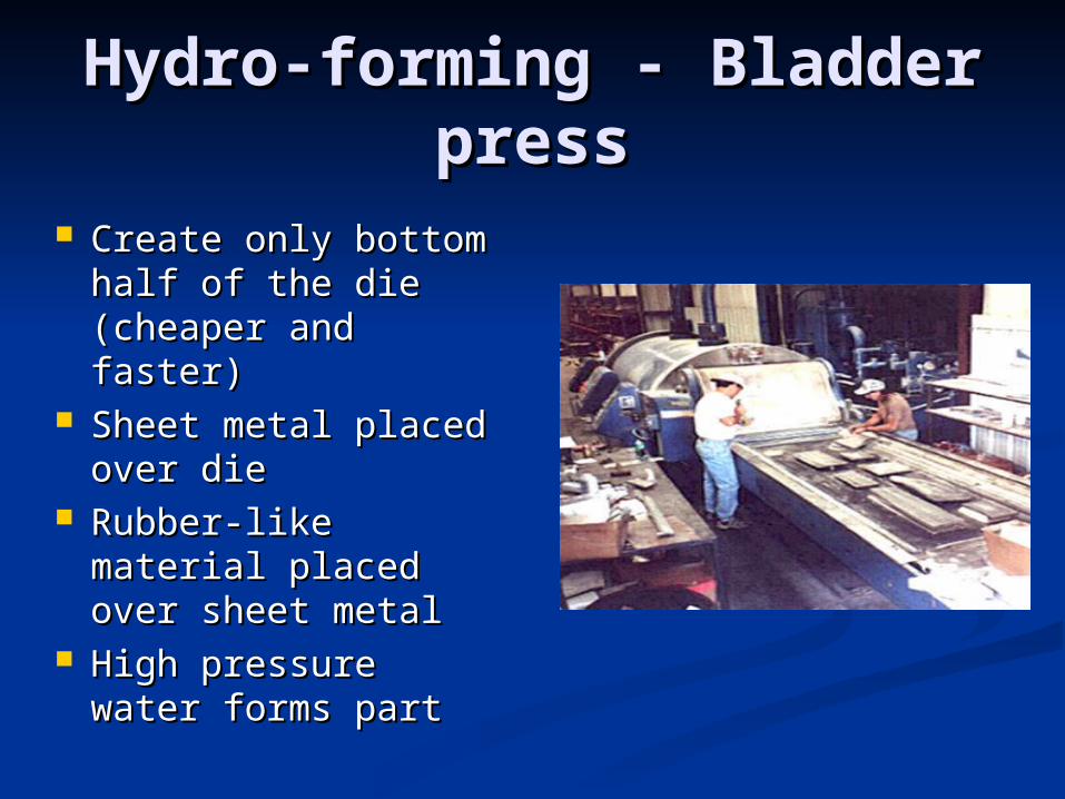
Hydro-forming - Bladder Hydro-forming - Bladder presspress
Create only bottom Create only bottom half of the die half of the die (cheaper and faster)(cheaper and faster)
Sheet metal placed Sheet metal placed over dieover die
Rubber-like Rubber-like material placed material placed over sheet metalover sheet metal
High pressure High pressure water forms partwater forms part

Progressive DiesProgressive Dies
Dies fed directly Dies fed directly from steel coilfrom steel coil
No need for No need for blanking operationblanking operation
Scrap get cut away Scrap get cut away as part gets as part gets formedformed
Restricted to Restricted to simple partssimple parts

Flexible Forming DiesFlexible Forming Dies

Rubber Pad DiesRubber Pad Dies

Tooling MaterialsTooling Materials
AgendaAgenda CuttingCutting
Theory of Cutting Sheet MetalTheory of Cutting Sheet Metal Forces for CuttingForces for Cutting Die Cutting OperationsDie Cutting Operations
Properties of Metals (stress strain curve, Properties of Metals (stress strain curve, spring back, etc)spring back, etc)
FormingForming BendingBending Embossing and Miscellaneous FormingEmbossing and Miscellaneous Forming DrawingDrawing
ToolingTooling Design PracticesDesign Practices

Stamping ApplicationsStamping Applications
Can accommodate many functional Can accommodate many functional features and attachment featuresfeatures and attachment features
Natural uniform wall thicknessNatural uniform wall thickness Can incorporateCan incorporate
SpringsSprings Snap fitSnap fit TabsTabs Spot weldingSpot welding
Material Thickness from .001 in to .790 Material Thickness from .001 in to .790 inin

ProductionProduction 35 to 500 parts per minute35 to 500 parts per minute 250000 per year minimum to justify 250000 per year minimum to justify
using progressive dieusing progressive die Progressive Die should eliminate at least Progressive Die should eliminate at least
two secondary operations before two secondary operations before considerationconsideration
Short run press tooling – Short run is Short run press tooling – Short run is when the cost of the tool exceeds the when the cost of the tool exceeds the cost of the partscost of the parts
Punch presses should be used for low Punch presses should be used for low volume parts when possiblevolume parts when possible

MaterialsMaterials
Any material that can be produced in Any material that can be produced in sheet can be press-workedsheet can be press-worked Deep drawn parts require “Draw Deep drawn parts require “Draw
Quality” steelsQuality” steels Non-ferrous metals may require Non-ferrous metals may require
modified processing or additional modified processing or additional processing stepsprocessing steps

Design Design RecommendationsRecommendations
Shaping and nesting on stripShaping and nesting on strip Stamp multiple parts on same strip to increase strip Stamp multiple parts on same strip to increase strip
utilizationutilization Design part/strip so part can be “cut-off”, not Design part/strip so part can be “cut-off”, not
“blanked”“blanked” HolesHoles
Diameter not less then T, spacing should be 2T to Diameter not less then T, spacing should be 2T to 3T3T
1.5 to 2T between a hole and edge1.5 to 2T between a hole and edge 1.5T + bending radius spacing between surface and 1.5T + bending radius spacing between surface and
holehole Use pilot holes Use pilot holes

Design Design RecommendationsRecommendations
Avoid sharp cornersAvoid sharp corners Improves tool wearImproves tool wear Increases bur sizeIncreases bur size Lowers stressLowers stress Minimum radius of .5T or .03125Minimum radius of .5T or .03125
Be aware of grain directionBe aware of grain direction Long sections should greater than Long sections should greater than
1.5T wide to avoid distortion and a 1.5T wide to avoid distortion and a weak problematic tool designweak problematic tool design

Design Design RecommendationsRecommendations
Use stiffening ribs or darts when Use stiffening ribs or darts when more strength is neededmore strength is needed
Use extruded holes when threaded Use extruded holes when threaded fasteners must be used (1.5 T is the fasteners must be used (1.5 T is the max thread contact you can achieve)max thread contact you can achieve)
Set-outs – used for location, rivets, Set-outs – used for location, rivets, etc. etc. Height to be .5THeight to be .5T
Be aware of the burrBe aware of the burr

Dimensional Dimensional ConsiderationsConsiderations
Spring-back, die wear, material Spring-back, die wear, material variation (temper, thickness, variation (temper, thickness, content) are sources of variationcontent) are sources of variation
Short run prototype stampings Short run prototype stampings should represent the dimensional should represent the dimensional population of the production tooled population of the production tooled parts to prevent system failures parts to prevent system failures when part goes into productionwhen part goes into production
Related Documents