
Welcome message from author
This document is posted to help you gain knowledge. Please leave a comment to let me know what you think about it! Share it to your friends and learn new things together.
Transcript

DWR-NPDES/SOP-G-01-WW Design Criteria Chapter 01-110117 Design Criteria for Review of Sewage Works Construction Plans and Documents- Chapter 1
THIS PAGE INTENTIONALLY LEFT BLANK
Design Criteria for Review of Sewage Works Construction Plans and Documents
Effective Date: November 1, 2017
Document No. DWR-NPDES/SOP-G-01-WW Design Criteria Chapter 1-110117
Department of Environment and Conservation
Division of Water Resources
https://www.tn.gov/environment/program-areas/wr-water-resources-home.html

DWR-NPDES/SOP-G-01-WW Design Criteria Chapter 1-110117 Design Criteria for Review of Sewage Works Construction Plans and Documents Chapter 1
November 1, 2017
THIS PAGE INTENTIONALLY LEFT BLANK
DWR-NPDES/SOP-G-01-WW Design Criteria Chapter 1-110117 Design Criteria for Review of Sewage Works Construction Plans and Documents Chapter 1
November 1, 2017
DESIGN CRITERIA FOR REVIEW OF SEWAGE WORKS CONSTRUCTION PLANS AND DOCUMENTS
TABLE OF CONTENTS (110117) PAGE
CHAPTER 1 General Engineering Requirements (110117) 1-1 App 1-A: Current Emphasis in Design Criteria App 1-B: Bibliography App 1-C: Integration of Permitting and Plans Review by Rule App 1-D: Specific Submittal Guidance by Phase and Project Type
App 1-E: Preliminary Engineering Report (PER) Guidance App 1-F: Corrective Action Plan/Engineering Report (CAP/(P)ER) Guidance
App 1-G: Construction Document Fees Guidance CHAPTER 2 Sewers and Sewage Pump Stations (072814) 2-1 (to be renamed: “Collection Systems” in the future) App 2-A: Design Basis for Wastewater Flow & Loadings App 2-B: Bibliography (to be provided) App 2-C: Sewer Integrity Metrics (to be provided)
App 2-D: Checklist for Small, Non-Treatment Projects (to be provided)
App 2-E: CMOM Program Guidance (to be provided) App 2-F: Limiting Pipe & Trenching Impact (to be provided) CHAPTER 3 Laboratories, Personnel, Maintenance Facilities (040196) And Safety Design 3-1 App 3-A: On-site Checklist CHAPTER 4 Preliminary and Pretreatment Facilities (040196) 4-1 CHAPTER 5 Clarifiers (040961) 5-1 (to be renamed: Clarifiers and Membranes) CHAPTER 6 Fixed Film Reactors (040196) 6-1 CHAPTER 7 Activated Sludge (022696) 7-1
CHAPTER 8 Nitrification (022696) 8-1 CHAPTER 9 Ponds and Aerated Lagoons (022696) 9-1 CHAPTER 10 Disinfection (080495) 10-1
DWR-NPDES/SOP-G-01-WW Design Criteria Chapter 1-110117 Design Criteria for Review of Sewage Works Construction Plans and Documents Chapter 1
November 1, 2017
CHAPTER 11 Tertiary Treatment/Advanced Wastewater 11-1 Treatment (082312) CHAPTER 12 Sludge Processing and Disposal (040196) 12-1
CHAPTER 13 Plant Flow Measurements and Sampling (040196) 13-1 CHAPTER 14 Instrumentation, Control and Electrical Systems 14-1 (040196)
CHAPTER 15 Small Alternative Wastewater Systems (031210) 15-1 App 15-A: Recirculation Tank/Pump System Example CHAPTER 16 Design Guidelines for Wastewater Treatment Systems
Using Spray Irrigation (012710) 16-1
CHAPTER 17 Design Guidelines for Wastewater Dispersal Using Drip Irrigation (012710) 17-1 App 17-A: Hydraulic Values & Conversion Factors App 17-B: Example Hydraulic & Nutrient Loading Calculations App 17-C: Derivation of Conversion Factor for Eqn.17-2
CHAPTER 18 Reserved (Deleted: Collection System Rehabilitation) 18-1 CHAPTER 19 Reserved (Future: Beneficial Re-Use Systems) (TBA) 19-1 App 19-B: Bibliography Chapter 19 (TBA)
DWR-NPDES/SOP-G-01-WW Design Criteria Chapter 1-110117 Design Criteria for Review of Sewage Works Construction Plans and Documents
Chapter 1
November 1, 2017 1-1 Design Criteria Ch. 1
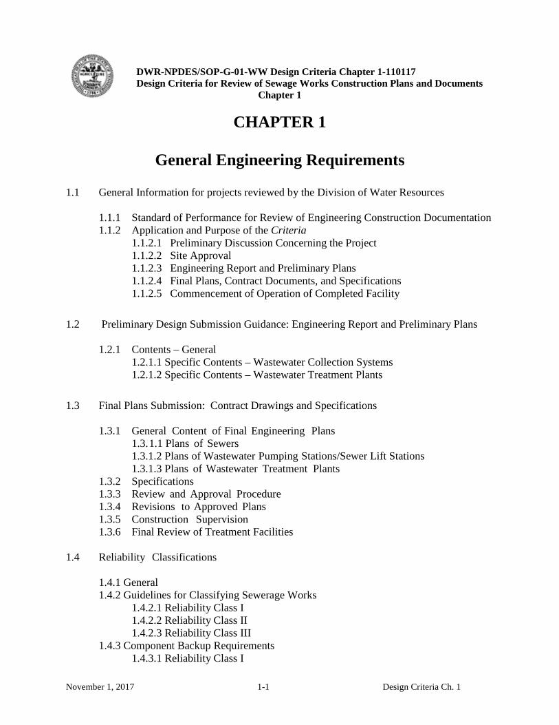
CHAPTER 1
General Engineering Requirements
1.1 General Information for projects reviewed by the Division of Water Resources
1.1.1 Standard of Performance for Review of Engineering Construction Documentation 1.1.2 Application and Purpose of the Criteria 1.1.2.1 Preliminary Discussion Concerning the Project 1.1.2.2 Site Approval 1.1.2.3 Engineering Report and Preliminary Plans 1.1.2.4 Final Plans, Contract Documents, and Specifications
1.1.2.5 Commencement of Operation of Completed Facility
1.2 Preliminary Design Submission Guidance: Engineering Report and Preliminary Plans
1.2.1 Contents – General 1.2.1.1 Specific Contents – Wastewater Collection Systems 1.2.1.2 Specific Contents – Wastewater Treatment Plants
1.3 Final Plans Submission: Contract Drawings and Specifications
1.3.1 General Content of Final Engineering Plans 1.3. 1.1 Plans of Sewers 1.3.1.2 Plans of Wastewater Pumping Stations/Sewer Lift Stations 1.3.1.3 Plans of Wastewater Treatment Plants
1.3.2 Specifications 1.3.3 Review and Approval Procedure 1.3.4 Revisions to Approved Plans 1.3.5 Construction Supervision 1.3.6 Final Review of Treatment Facilities
1.4 Reliability Classifications 1.4.1 General 1.4.2 Guidelines for Classifying Sewerage Works 1.4.2.1 Reliability Class I 1.4.2.2 Reliability Class II 1.4.2.3 Reliability Class III 1.4.3 Component Backup Requirements 1.4.3.1 Reliability Class I
DWR-NPDES/SOP-G-01-WW Design Criteria Chapter 1-110117 Design Criteria for Review of Sewage Works Construction Plans and Documents
Chapter 1
November 1, 2017 1-2 Design Criteria Ch. 1
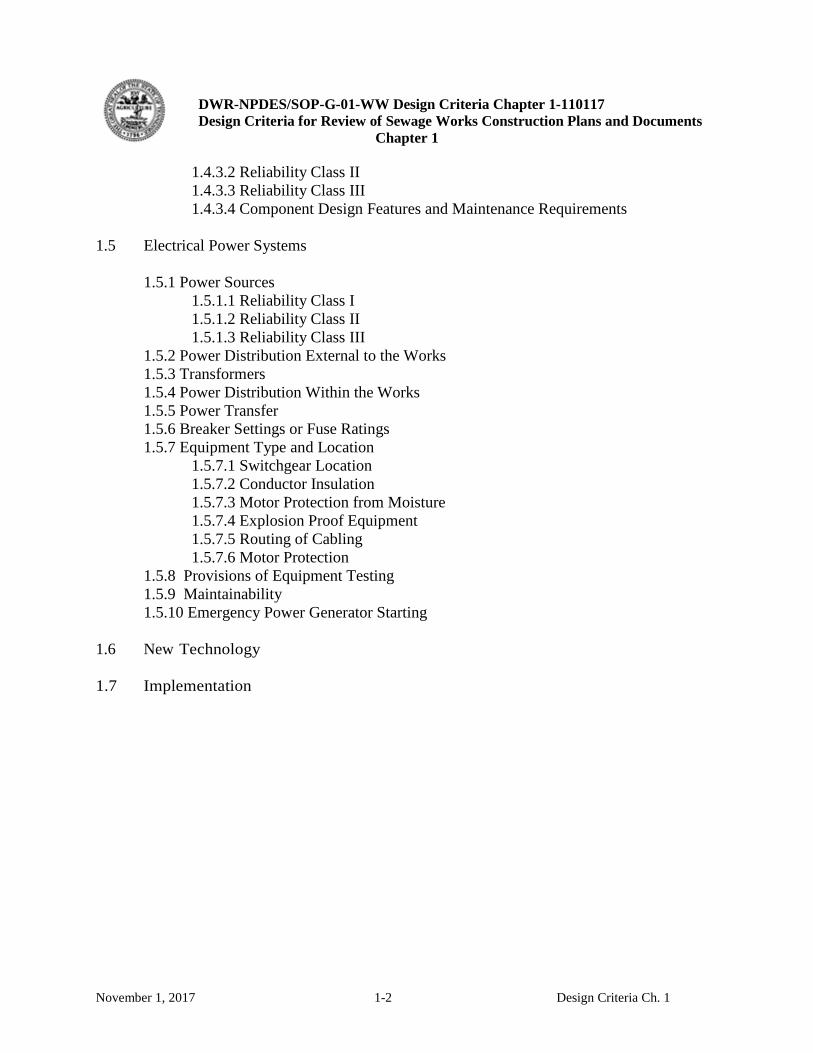
1.4.3.2 Reliability Class II 1.4.3.3 Reliability Class III 1.4.3.4 Component Design Features and Maintenance Requirements 1.5 Electrical Power Systems 1.5.1 Power Sources 1.5.1.1 Reliability Class I 1.5.1.2 Reliability Class II 1.5.1.3 Reliability Class III 1.5.2 Power Distribution External to the Works 1.5.3 Transformers 1.5.4 Power Distribution Within the Works 1.5.5 Power Transfer 1.5.6 Breaker Settings or Fuse Ratings 1.5.7 Equipment Type and Location 1.5.7.1 Switchgear Location 1.5.7.2 Conductor Insulation 1.5.7.3 Motor Protection from Moisture 1.5.7.4 Explosion Proof Equipment 1.5.7.5 Routing of Cabling 1.5.7.6 Motor Protection 1.5.8 Provisions of Equipment Testing 1.5.9 Maintainability
1.5.10 Emergency Power Generator Starting 1.6 New Technology 1.7 Implementation
DWR-NPDES/SOP-G-01-WW Design Criteria Chapter 1-110117 Design Criteria for Review of Sewage Works Construction Plans and Documents
Chapter 1
November 1, 2017 1-3 Design Criteria Ch. 1
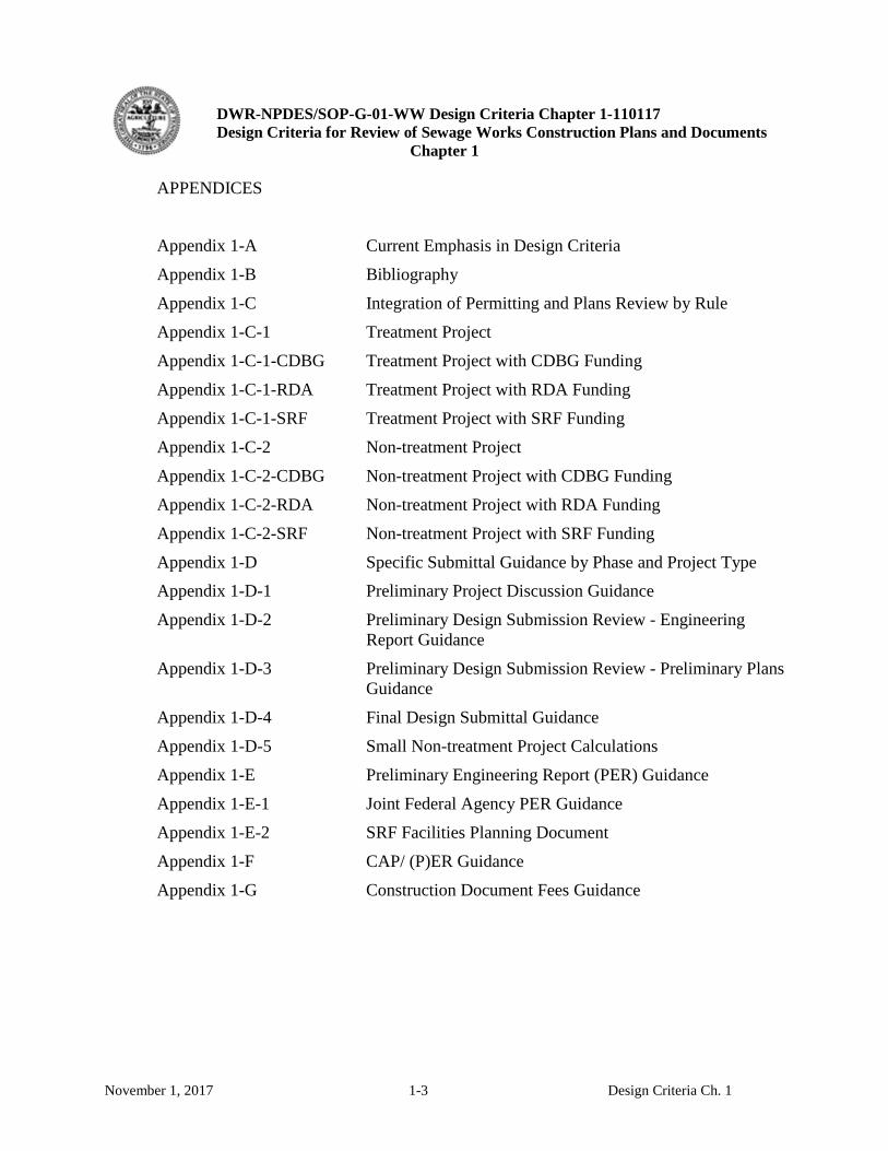
APPENDICES
Appendix 1-A Current Emphasis in Design Criteria
Appendix 1-B Bibliography
Appendix 1-C Integration of Permitting and Plans Review by Rule
Appendix 1-C-1 Treatment Project
Appendix 1-C-1-CDBG Treatment Project with CDBG Funding
Appendix 1-C-1-RDA Treatment Project with RDA Funding
Appendix 1-C-1-SRF Treatment Project with SRF Funding
Appendix 1-C-2 Non-treatment Project
Appendix 1-C-2-CDBG Non-treatment Project with CDBG Funding
Appendix 1-C-2-RDA Non-treatment Project with RDA Funding
Appendix 1-C-2-SRF Non-treatment Project with SRF Funding
Appendix 1-D Specific Submittal Guidance by Phase and Project Type Appendix 1-D-1 Preliminary Project Discussion Guidance
Appendix 1-D-2 Preliminary Design Submission Review - Engineering Report Guidance
Appendix 1-D-3 Preliminary Design Submission Review - Preliminary Plans Guidance
Appendix 1-D-4 Final Design Submittal Guidance
Appendix 1-D-5 Small Non-treatment Project Calculations
Appendix 1-E Preliminary Engineering Report (PER) Guidance
Appendix 1-E-1 Joint Federal Agency PER Guidance
Appendix 1-E-2 SRF Facilities Planning Document
Appendix 1-F CAP/ (P)ER Guidance
Appendix 1-G Construction Document Fees Guidance

DWR-NPDES/SOP-G-01-WW Design Criteria Chapter 1-110117 Design Criteria for Review of Sewage Works Construction Plans and Documents
Chapter 1
November 1, 2017 1-4 Design Criteria Ch. 1
THIS PAGE INTENTIONALLY LEFT BLANK
DWR-NPDES/SOP-G-01-WW Design Criteria Chapter 1-110117 Design Criteria for Review of Sewage Works Construction Plans and Documents
Chapter 1
November 1, 2017 1-5 Design Criteria Ch. 1
GENERAL ENGINEERING REQUIREMENTS
1.1 General Information for projects reviewed by the Division of Water Resources 1.1.1 Standard of Performance for Review of Engineering Construction Documentation
All chapters of this Design Criteria for Review of Sewerage Works Construction Documents (the Criteria) have been developed to assist in achieving a standard of performance embodied in State Law and Rules. This chapter of the Criteria assists in meeting the following performance standards for engineering documents prepared for sewerage works projects in the State as authorized primarily in the TDEC Rules Chapter 0400-40-02, REGULATIONS FOR PLANS, SUBMITTAL, AND APPROVAL; CONTROL OF CONSTRUCTION; CONTROL OF OPERATION and Chapter 0400-40-16, PUBLIC SEWERAGE SYSTEMS. • All engineering documents should reflect generally accepted wastewater engineering
practice as defined by the Criteria or present adequate justification for systems proposed outside the Criteria’s guidance. All project reports, plans and specifications should reflect appropriate attention to: o Protection of public health and safety of operating personnel and equipment; o Achievement of environmental protection as defined by permit compliance
requirements; o System reliability, flexibility, expandability, maintainability, operability and
sustainability; and o Cost effectiveness.
• Plans (preliminary or final), engineering reports (basis of design), and specifications submitted for review and approval should enable a technically qualified reviewer to efficiently determine that the documents have been prepared with due diligence with respect to (1) existing and foreseen circumstances such as influent flow and character, (2) appropriate and demonstrated treatment or hydraulic capabilities, and (3) follow-on construction, start-up, commissioning, and operation of the systems to achieve permitted results;
• Final plans, specifications and engineering reports should support the level of detail required for the procurement method intended;
• Record drawings, specifications and engineering reports should support the preparation of operational and maintenance (O&M) manuals, training, troubleshooting, and decisions on future upgrades or modifications.
DWR-NPDES/SOP-G-01-WW Design Criteria Chapter 1-110117 Design Criteria for Review of Sewage Works Construction Plans and Documents
Chapter 1
November 1, 2017 1-6 Design Criteria Ch. 1
The cited chapters in the TDEC Rules define this Design Criteria’s scope of applicability to all wastewater treatment projects including industrial and domestic as well as conveyance projects. The same Rules direct the Commissioner of the Tennessee Department of Environment and Conservation (TDEC) to determine the requirements for submission of construction documents relative to these projects and gives TDEC the latitude to scale the submission requirements appropriately for the size and complexity of the projects; specifically the Rules require that wastewater treatment projects receive more and earlier attention in the design process than conveyance type wastewater projects. Construction projects that constitute repairs or maintenance or replacement of material or equipment in kind need not meet the submittal requirements in this chapter. If a project would change the treatment plant (regardless of size or type; conventional or decentralized) process flow diagram (or more detailed process and instrumentation diagrams, P&ID), or change plant hydraulics, controls, capacity, discharge characteristics or equipment, the submittal steps outlined in this chapter should be followed. For conveyance projects such as gravity sewers, pump stations, equalization basins and force mains, final plans, specifications and either engineering reports or calculations shall be submitted if hydraulic characteristics or locations will be modified by the construction. State review and approval of rehabilitation line work on collection systems need not be submitted for review or approval unless pipe interior diameters (IDs) decrease by 15% or funding agencies require state approval of plans and specifications. The specific “4-step” process outlined in this chapter for all treatment process projects may be followed when conveyance projects are of such scope and complexity that the early and additional review is deemed beneficial by the submitting activity. Purely industrial plant conveyance projects will not be reviewed; internal beneficial reuse upstream of a treatment plant will not be reviewed. “Small domestic wastewater plants” receive special attention and the Rules (Chapter 0400-40-02-.03(3) effective December 16, 2013) specifically restrict “activated sludge” configurations (in the case of a plant up to 30,000 gallons per day (gpd)) or discourage “activated sludge” processes (in plants between 30,000 and 100,000 gpd) unless all other options are demonstrated to be impractical. “Suspended growth activated sludge” processes are envisioned in this prohibition due to the operational complexity of their sludge management and the difficulty of these smaller systems to accommodate the adverse impacts of inflow and infiltration (I&I) in the influent. “Attached growth” biological systems are not considered to be covered by this “package plant prohibition”. Sequencing batch reactors (SBRs) with adequate volume to achieve a valid level of equalization with tertiary filtration or membrane bioreactors (MBRs) with adequate equalization provided separately are also currently considered to be exempt from this restriction.
DWR-NPDES/SOP-G-01-WW Design Criteria Chapter 1-110117 Design Criteria for Review of Sewage Works Construction Plans and Documents
Chapter 1
November 1, 2017 1-7 Design Criteria Ch. 1
Appendix 1-A provides current Division of Water Resource’s areas of emphasis that bear on engineering document requirements, particularly preliminary engineering reports (PERs).
1.1.2 Application and Purpose of the Criteria
This Criteria applies to the development, design, and submission of engineering documents for projects that convey or treat wastewater in the State of Tennessee including: • Municipal, utility district or legally constituted water and wastewater authorities
sewerage systems, subdivisions, trailer parks, apartments, resorts, etc. • Publicly or privately owned sewerage systems required to obtain a charter (Certificate
of Convenience and Necessity, or CCN) from the Public Utility Commission (PUC) formerly the Tennessee Regulatory Authority (TRA).
• Public corporation sewerage systems organized under the General Corporation Act of Tennessee.
• Public sewerage systems organized under the Federal Housing Authority Title bond. • All sewerage systems owned by the State of Tennessee. • Industrial wastewater treatment systems. • Federally owned systems. • Sewerage systems (often decentralized) for schools, service stations, shopping
centers, truck stops, or motels. • Sewerage and industrial wastewater systems for laundries and car wash facilities. • Pump and haul systems.
These Criteria are not sufficiently comprehensive to apply to all wastewater treatment and disposal projects in the State. However, the Criteria will represent the State’s engineering community’s generally accepted and acceptable standards for design of projects to protect the public welfare and maintain protective environmental conditions of the state’s waters. “The engineering report and preliminary plans shall be prepared in accordance with generally accepted wastewater engineering practices. The Design Criteria published from time to time are used internally by the Division as a compilation of such practices and are available to the public. Other designs may also be used if adequately supported by calculations and actual testing data. (Chapter 0400-40-02-.03(2) Effective December 16, 2013) Bibliographies at the end of each chapter are provided as references for justification and guidance beyond that provided in the Criteria. (See Appendix 1-B for Chapter 1.) The Criteria provides flexibility during the design and review process for inclusion of technical advances, new products, and innovative approaches based on sound engineering
DWR-NPDES/SOP-G-01-WW Design Criteria Chapter 1-110117 Design Criteria for Review of Sewage Works Construction Plans and Documents
Chapter 1
November 1, 2017 1-8 Design Criteria Ch. 1
judgement. The purpose of Chapter 1 is to outline the process for the submission of engineering documents for wastewater construction projects to the Division of Water Resources. The reader is directed to Rules cited in the Bibliography of this chapter for additional details. Appendix 1-C depicts in summary form the steps in the treatment and non-treatment submittal processes and integrates the permitting and plans approval process from project initiation to construction completion and operation for projects with and without the most common public funding assistance. The Division requires (Chapter 0400-40-02-.01 Effective December 16, 2013) the preparation of technical engineering information to be performed by an engineer who has obtained professional licensure to practice within the State of Tennessee, representing the municipality, utility, industry, or owner. The engineer of record (EOR) for Preliminary Engineering Reports (PERs), Engineering Reports (ERs), final plans, and final specifications shall be professionally responsible for the contents therein and nothing in this Criteria relieves him/her of that responsibility. Preliminary plans, while not sealed, should be consistent with engineering documents with which submitted.
1.1.2.1 Preliminary Discussion Concerning the Project; Rules Section 0400-40-02-.02 (effective
December 16, 2013)
The engineer employed by the person who is planning to carry out an activity requiring plans approval as outlined in T.C.A. Section 69-3-108 should make written request for a meeting with representatives of the Commissioner for an informal discussion of the project with relation to its scope and purpose. Such meeting should be held within 30 days from the receipt of the request. At this meeting the engineer should make available to the representative of the Commissioner general information regarding the proposed point of discharge, quantity and quality of discharge, land and water use in the vicinity of the proposed discharge and general information regarding the anticipated effect which the proposed activity may have on the surrounding area. The preliminary data will be reviewed and, if sufficient to indicate the scope and extent of the project, the representatives of the Commissioner will outline general requirements for its official approval…” The scope, location, method of communication, and attendees of the Preliminary Discussion are dependent on the complexity (both engineering and permitting) of the project. The engineer should request and schedule the discussion with the Division, review the proposed agenda and prepare for the meeting so that attendees have sufficient information available to make an assessment of the project and identify the steps necessary for approval of the project. Division representatives attending shall be selected based on the information provided by the engineer and the types of plan review and permit issues. To assist in determining the preparation requirements for this meeting, an agenda/checklist for the meeting by project type is provided in Appendix 1-D-1 of this chapter. The Division will attempt to identify the most expeditious path forward and at the end of the discussion the engineer, owner and funding representatives should have an
DWR-NPDES/SOP-G-01-WW Design Criteria Chapter 1-110117 Design Criteria for Review of Sewage Works Construction Plans and Documents
Chapter 1
November 1, 2017 1-9 Design Criteria Ch. 1
outline of requirements for the preliminary and final submissions and permitting steps likely required to aid in a coordinated design and permitting effort. Decisions relative to the preliminary submission requirements and any alternatives to be analyzed or considered will be made at the Preliminary Discussion if at all possible. If information, investigations, sampling, modelling or other research is identified to specify the plant’s effluent limits, the path forward to complete these requirements will be outlined.
1.1.2.2 Site Approval; Rules Section 0400-40-02-.04 (effective December 16, 2013)
The proposed site for any treatment works or facilities shall be made available to representatives of the Commissioner for inspections at or prior to the time that the preliminary information and/or engineering report and preliminary plans are submitted for approval. The representative of the Commissioner may specify, in the letter of acceptance and approval of the preliminary report and preliminary plans, any specific requirements, such as effluent limitations or other restrictions which must be met by the proposed facilities. Preparation of final plans and specifications should not be commenced prior to receipt of an official site approval letter or notification to proceed.” In addition to approval for the physical site of the project, this phase provides the path forward to determine discharge requirements to be included in the permit application and to inform the plant process design. Investigations to assess receiving water assimilative capacity, and land assimilative capacity for land application, and beneficial reuse parameters will be defined. The engineer and owner shall submit a permit application, modification or amendments. While this phase usually is conducted prior to the Preliminary Design Submission, the end of the Site Approval and the Preliminary Design phases is marked with a common Site Approval Letter/Preliminary Design Submission Approval Letter authorizing completion of the design and Final Plans Submission as well as normally the drafting and posting for public comment the permit, permit modification and/or amendments.
1.1.2.3 Engineering Report and Preliminary Plans; Rules Section 0400-40-02-.03 (effective
December 16, 2013)
“Unless exempted, an engineering report and preliminary plans must be prepared and presented in accordance with the requirements of the representatives of the Commissioner. The engineering report with preliminary plans must conform to the guidelines for such reports and plans as published by the Tennessee Department of Environment and Conservation. The report shall contain all required information of adequate design evaluation of the proposed waste treatment facilities and shall include such results of waste and water analyses, treatability or pilot treatment studies and investigations that may be required by the Commissioner’s representatives…These data will be reviewed and, if sufficient to evaluate the effect of the project, the Commissioner’s representative, will confirm acceptance of the preliminary information by official site
DWR-NPDES/SOP-G-01-WW Design Criteria Chapter 1-110117 Design Criteria for Review of Sewage Works Construction Plans and Documents
Chapter 1
November 1, 2017 1-10 Design Criteria Ch. 1
approval letter and instruct the engineer to proceed with the development of final plans and specifications…” This section clearly stipulates that a preliminary submission of Engineering Report and Preliminary Plans is required for a treatment process. Conventional treatment plants, “decentralized” plants and land application designs are considered to require the preliminary submission in addition to the final design submission. Chapter 0400-40-02-.03 effective December 16, 2013 requires that guidelines for the engineering report and preliminary plans be provided by the Division. Appendix 1-D-2 and 3 provide guidance for the preliminary design submission by project type. Use of these checklists is optional for non-treatment processes. Detailed technical submittal requirements for conveyance projects will be included in Chapter 2. It is the intention in the preliminary design submission (ER and preliminary plans) for the engineer to provide via the owner, the process design details such that the Division can assess whether the project is likely to be successful in achieving permit requirements (either NPDES discharge, land application or beneficial reuse) and if due diligence in the design especially with respect to the characterization of the influent components and flows has been demonstrated. The Division should be able to determine from the Preliminary Submission if the Criteria guidelines will be achieved or that sound engineering arguments have been made to support any departures from the Criteria.
The Engineering Report is the primary means to provide evidence of due diligence performed and should be written assuming someone unfamiliar with the existing situation or problem can effectively review the proposed specific solution. It should demonstrate to the Division the design’s efficacy. It is not expected that there will be many changes, if any, in process parameters between the Engineering Report submitted as part of the Preliminary Design Submittal and the Final Plans. Appendix 1-D-2 can be used as a general checklist. Preliminary Plans are a small subset of the final plans concentrating on the process and meeting the general submission characteristics of Appendix 1-D-3 as applicable. The Criteria draws a distinction between the Engineering Report (ER) required as part of the “regulations for plans, submittal, and approval” process and a “Preliminary Engineering Report” (PER). A PER submission is usually required: (1) by funding agencies to define the situation, problems and project objectives, identify overall options to achieve the objectives and perform life cycle cost analyses (LCCA) as part of selecting a cost effective alternative; (2) by the Division permitting staff to ensure evaluation of the location and quantity of discharged, land applied or beneficially re-used reclaimed wastewater or (3) to evaluate process and discharge alternatives. Although the PER may be part of the Tennessee design plans approval and/or permitting process, the standards for and prescribed contents of the PER have not been separately prescribed in this Criteria; they have been adequately outlined by a joint committee representing federal
DWR-NPDES/SOP-G-01-WW Design Criteria Chapter 1-110117 Design Criteria for Review of Sewage Works Construction Plans and Documents
Chapter 1
November 1, 2017 1-11 Design Criteria Ch. 1
funding agencies. During the “Preliminary Discussion Concerning the Project” alternatives to satisfy the Division’s specific concerns will be discussed. (Requirements of a PER specified by the joint federal agencies is included as Appendix 1-E-1). Federal guidelines for PERs require the engineer to perform Life Cycle Cost Analyses (LCCAs) as part of the report. These LCCAs are usually performed prior to or during the early stages of the “Site Approval” phase. Alternatives evaluations in PERs generally lack the design and procurement specificity to judge the design’s conformance to the more detailed requirements of this Criteria. Therefore PERs do not remove the requirement for the ER submitted with the preliminary plans or the final plans. The ER required by Chapter 0400-40-02 of the Rules envisions a report that may be more accurately referred to as a “basis of design” or “design memorandum” in other design contexts. The ER should enable the Division to determine if the design agent has exercised due diligence in collecting, projecting and analyzing the impact of anticipated current and future influent conditions, whether plant unit processes meet the Criteria or are otherwise justified by calculations, studies or analogy with other similar systems in operation and can be expected to achieve permit discharge requirements reliably and sustainably. It may be appropriate to include the ER as an expanded section in the PER as part of the recommended option. Fees appropriate for engineering reports are payable upon submission of PERs and ERs. See Appendix 1-G.
1.1.2.4 Final Plans, Contract Documents, and Specifications; Rules Section 0400-40-02-.05 (effective December 16, 2013)
Construction work shall not be commenced on any new construction or major change of existing facilities or for any activity outlined in T.C.A Section 69-3-108 until complete and final plans and specifications for such activities have been submitted to and approved in writing by an authorized representative of the Commissioner…” This requirement applies to all sewerage works projects unless specifically excluded elsewhere. An Engineering Report is required at this point if not previously submitted as part of a preliminary design submittal (or if there have been significant process changes from the previously submitted engineering report; See Appendix 1-D-2 and -3). If this is the only set of plans submitted, requirements of the preliminary design submittal should be contained in this final submission. These “final plans” (often called the “contract documents” or “CDs”) consist of a final sealed plan set and “project manual” containing the procurement specifications and the technical specifications. They must receive the Division’s review and approval prior to construction commencing. If the final design is accurately reflected in the preliminary design submission, the final review process should proceed efficiently with minimal intervention or delay by the Division. Note that the Rules Section 0400-40-05-.05 (8) require that any associated permit that applies to the
DWR-NPDES/SOP-G-01-WW Design Criteria Chapter 1-110117 Design Criteria for Review of Sewage Works Construction Plans and Documents
Chapter 1
November 1, 2017 1-12 Design Criteria Ch. 1
proposed project have satisfactorily completed the public comment period before the final approval can be provided by the Division. The Division has delegated authority to some municipal agencies to review plans and specifications for sewer line extensions, sewer lift stations and sewer rehabilitation projects. Agencies receiving this delegation shall certify periodically that their review is based on the current Criteria used by the Division or standards of the municipality whichever is more stringent. Fees listed in Appendix 1-G shall be due with submission of the final plans and specifications and, if necessary, the revised engineering report. Note that, in accordance with Chapter 0400-40-02-.07, “the submission of letters, reports, plans and specifications shall constitute an application for a permit… The official letter issued by the Commissioner’s representative approving a project for construction in accordance with submitted plans and specifications, together with the plans and specifications bearing the official “Approved for Construction” stamp of the Commissioner shall constitute a valid permit to construct, install or modify in conformance with all conditions shown and specified in the approved plans and specifications…” Chapter 0400-40-02-.08 states: …” It shall be the engineer’s or responsible person’s responsibility to inspect or insure inspection of construction of the facilities and to assist in commencement of operation and to verify that completed facilities are in accordance with approved plans and specifications at the time of the final inspection”.
1.1.2.5 Commencement of Operation of Completed Facility, Rules Section 0400-40-02-.09 (effective December 16, 2013)
“The start-up of the completed facility shall be attended by the engineer, the agent or agents designated by the responsible person to be in charge of the operation and maintenance of the works, the Commissioner’s representative and any others deemed necessary. The engineer shall instruct the person or the person’s agent in the proper operation and maintenance of the facilities and shall present them with a complete manual outlining the proper operation and maintenance procedures to be followed…The engineer and the Commissioner’s representative shall instruct the person or the person’s agent in the required points of sampling, methods for and number of analyses, reporting techniques, reporting frequency and any other information deemed pertinent to compliance with the intent of the Water Quality Control Act of 1977…”
DWR-NPDES/SOP-G-01-WW Design Criteria Chapter 1-110117 Design Criteria for Review of Sewage Works Construction Plans and Documents
Chapter 1
November 1, 2017 1-13 Design Criteria Ch. 1
1.2 Preliminary Design Submittal Guidance: Engineering Report and Preliminary Plans
Refer to checklists in the Appendices for the requirements specifically required for the Preliminary Design and the Final Design submissions. The Division will review and either approve or comment on the engineering report submittal within 30 days. Generation of the Engineering Report at the end of the preliminary design phase when required or with submission accompanying the final plans is an important step: • It clarifies the proposed project cost, both capital and operational, to the owner and
creates the opportunity for any clarification in the project objectives, capabilities, lack of capabilities, necessary requirements not previously discussed to prevent unrealized expectations at the end of the design phase.
• It promotes understanding between the owner and engineer of the consequences in terms of design budget and schedule of changes in the project characteristics after this point.
• It is the best time for an external review minimizing the impact of additional requirements or conditions.
• It focuses Divisional resources on the importance of the process and avoids the necessity of “back-engineering” process parameters from the plans alone, reducing errors in the review process.
• It provides guidance for the design process itself and reduces scope, and consequently budget, creep.
• If linked to Design Criteria parameters and checklists, it expedites the review process, reduces the chance of last minute changes and avoids delays at the final plans and specifications review stage when the design budget is usually expended.
1.2.1 Contents - General
The engineering report shall assemble the basic information, present the basis of design and any assumptions, and demonstrate compliance or the basis of exceptions to the Criteria. Although normally considered in the PER, the Division may request the engineer to evaluate alternative solutions remaining unresolved at this point especially with respect to specific types of equipment proposed or the disposition of process residuals not central to the process selected. The report, if provided at the preliminary design submittal stage, must be sufficiently complete to facilitate further detailed plans and specifications development. As a minimum, the engineering report for any project shall include the following information where appropriate;
DWR-NPDES/SOP-G-01-WW Design Criteria Chapter 1-110117 Design Criteria for Review of Sewage Works Construction Plans and Documents
Chapter 1
November 1, 2017 1-14 Design Criteria Ch. 1
• Purpose and need for the proposed project. • Present and design population with the method of determination • Nature and extent of the service area (including immediate and probable future
development) and therefore nutrient, contaminants and flow magnitude and periodicity of the waste loads at the time of commissioning and at the estimated time of achieving design flow conditions (usually the permit conditions). Anticipated I&I reduction projects should be included in the projections. Existing data should be provided and analyzed for at least a year and up to three years if existing.
• Description of the existing collection and/or treatment system, including its condition and problems, renovation and rehabilitation or replacement requirements.
• Detailed basis of design including reliable measurements or analysis of flow and wastewater constituents and hydraulic, organic and solids loadings attributed to residential, commercial, and industrial users. (See Chapter 2, Appendix 2-A for new systems or new additions for which data is not available.)
• The 100-year flood elevation (and 500 year flood elevation for USDA-RDA projects) relative to proposed projects if submitted during the preliminary design submission and as part of the final plans.
• All structures must comply with ASCE 7-10, Minimum Design Loads for Buildings and Other Structures, as identified in the current state building code, IBC-10. The link is found at: http://ascelibrary.org/doi/book/10.1061/asce7. This provision is very significant for protection in the 20 counties of West Tennessee where the greatest seismic risk exists in the New Madrid Seismic Zone. Certification shall be included with the final plans submission.
1.2.1.1 Specific Contents – Wastewater Collection Systems
• Any new sewer alignments or existing sewers replaced in the same trench that cross a stream or are within 50 feet of the bank of the stream may trigger a “site characterization” conducted by the Division to determine the potential for stream capture. The Division uses Guidance for Making Hydrologic Determinations, Version 1.4, May 2011, TDEC, as a reference for making a site characterization. A "Stream" means surface water that is not a wet weather conveyance. [Rule 1200-4-3-.04(20)] This is usually identified during the Preliminary Discussion or the Site Approval phases.
• If the site characterization indicates there is no potential for stream capture, then the provisions of a general Aquatic Resource Alteration Permit (ARAP) and the criteria in Chapter 2 of these Design Criteria apply.
• If the site characterization determines that there is potential for stream capture, then
DWR-NPDES/SOP-G-01-WW Design Criteria Chapter 1-110117 Design Criteria for Review of Sewage Works Construction Plans and Documents
Chapter 1
November 1, 2017 1-15 Design Criteria Ch. 1
the Engineering Report should include a plan to prevent stream capture. In such cases the Division highly recommends the process to obtain a site-specific ARAP be initiated at the planning stage. The characteristics of streams, hydrology, and subsurface conditions vary widely across the State. Therefore, the design engineer is enjoined to exercise judgment in the selection of appropriate site controls. For difficult site conditions, the Division may require the services of a Professional Geologist or hydrogeologist and an underground (geotechnical) survey. In some cases, it may be more economical to consider a different route for the sewer.
• The Division excludes from the requirements of the Criteria sewer rehabilitation work that does not reduce the cross-sectional area of the sewer pipe by less than 15 percent such as with cured-in-place rehabilitation. Submittal of an engineering report or construction plans and specifications is not required in this case unless funding agencies require it. The Division requires the submittal of an engineering report that includes calculations indicating the sewer capacity following rehabilitation relative to both existing and anticipated future flows to a 20 year horizon for sewer rehabilitation projects that do result in the decrease of the cross-sectional area of any sewer pipe by 15 percent or more. A reduction in capacity could be offset by work included in the project (or associated projects) to reduce I/I or redirect flows upstream of the rehabilitated pipe.
1.2.1.2 Specific Contents – Wastewater Treatment Plants
• Treatment process and schematic flow diagrams (process flow diagrams) giving the
plant unit design parameters; instrumentation and control features, remote monitored parameters and control elements; sequence and description of operational control systems, unit process capabilities and redundancy, design flow, and load basis for mass balances.
• Solids handling and disposal options and recommendations. • Soil and geologic conditions are required as part of the preliminary engineering
submittal for land application disposition of treated wastewater and these specific requirements are outlined in detail in Chapters 16 and 17 of this Sewerage Design Criteria. For other projects sufficient soils and geologic data shall be submitted no later than the Final Plans, Contract Drawings and Specifications submission. If there is any reason to doubt the geologic or soils condition are not appropriate for the project, their identity should be investigated as early in the design process as possible. At a minimum, the following is required: o Soil tests performed - sufficient to provide moisture and compaction data for
construction.
DWR-NPDES/SOP-G-01-WW Design Criteria Chapter 1-110117 Design Criteria for Review of Sewage Works Construction Plans and Documents
Chapter 1
November 1, 2017 1-16 Design Criteria Ch. 1
o Borings for representative subsurface conditions. A depth below the bottom footing grade of major structures as recommended by a licensed Tennessee geotechnical engineer.
o Boring logs or schematic drawings indicating changes of soil types and/or refusal depths.
o Unsuitable soil conditions with correction or removal contingencies. o Karst features with an evaluation of surface water drainage and recommendations
as appropriate from a hydrologist/geotechnical engineer licensed in the state of Tennessee.
o Rock above the bottom footing grade of structures—the Division requires representative core data to a depth recommended by a licensed Tennessee geotechnical engineer. The Division requires an indication of weathered rock conditions along with mud seams or weathered bedding planes.
• Domestic potable wells within 1000 feet of a plant should be located along with land use of the surrounding area (residential, agricultural, and industrial).
• The Division needs the submittal of a mass balance for all plants to approve plans. o The mass balances should include loadings to each unit process operations,
including all recycle, and side stream flows. Mass balances should include the following initial and design operating conditions: maximum, minimum, and average flow, BOD and suspended solids loadings; and maximum, minimum, and average nutrient loadings, especially nitrogen for plants with considerable industrial loadings and/or where nutrient removal will be required or recommended.
o The report should identify and be consistent with all applicable area-wide projects, drainage basins, service areas, comprehensive master growth plans, and metropolitan area plans; e.g., 208, and 303(e) plans.
o The design period should be for 20 years unless growth of the area dictates other design parameters.
o Preliminary plans can be included with the engineering report. The Division will review preliminary plans for adequacy, but not for construction approval.
1.3 Final Plans Submission: Contract Drawings and Specifications 1.3.1 General Content of Final Engineering Plans
All plans and specifications should be consistent with the approved engineering report. A revised engineering report should be submitted with the final plans and specifications if modifications to the preliminary design submission have been made. All plans for sewerage systems or wastewater treatment works should bear a title showing the name of

DWR-NPDES/SOP-G-01-WW Design Criteria Chapter 1-110117 Design Criteria for Review of Sewage Works Construction Plans and Documents
Chapter 1
November 1, 2017 1-17 Design Criteria Ch. 1
the municipality, sewer district, institution, or other owner, the owner’s signature of approval, and the seal and signature of the design engineer. The title should show the scale in feet, the north direction, and the date. The cover sheet and all other sheets should bear a general title and be logically numbered. Appropriate subtitles should be included on plan sheets. The plans should be clear, legible, and drawn to a scale that shows clearly all necessary information. The size of the plans should be approximately 24 inches by 36 inches or larger. Appendix 1-G provides details on copies and formats of submissions. A location map must be included with each set of plans. The cover letter or letter of transmittal should clearly indicate the system and design engineer with addresses. Appendix 1-D-2 provides information to be included in cover letters to assist in expeditious logging in and processing of submittals. If there is any doubt on the forms of the engineering documentation to be submitted, refer to the minutes of the preliminary project discussion meeting and/or check with the Division. Detail plans should include plan views, elevations, sections, profiles, and supplementary views. Plans should also specify dimensions and relative elevations of structures, the location and outline form of equipment, location and size of piping, water levels, ground elevation, and erosion control facilities. A fence should surround all wastewater treatment plants. The Division recommends a fence of metal fabric that is at least six feet high and of a type that is difficult to climb and topped with at least two strands of barbed wire. The exceptions to this type of fencing are lagoons and land application systems. Such treatment plants can use livestock fence, if a sufficient number of signs are attached which contain a warning against trespassing and indicate that the fenced area is used for treating wastewater. Generally, pumping stations should be fenced similarly to plants with the exception that the entrance tube to "canned" lift stations need not be fenced. The designer is encouraged to refer to the latest versions of the Criteria Appendices to this chapter for checklists and policy and to the accompanying chapters concentrating on specific types of projects and unit processes.
1.3.1.1 Plans of Sewers
The plans should show the location, size, and direction of flow of all proposed and existing sewers draining to the concerned treatment facility. Hydraulic calculations are required for all lines in the project if the submittal is to be deemed complete. The Division requires the clear showing of topography and elevations, both existing and proposed, and all bodies of water (including direction of flow and high water elevations). Hydraulic calculations for pumping stations should take into consideration existing loading plus anticipated future growth as well as projected loading from the proposed extension. All gravity conveyances should be depicted at one inch equal to 50 feet
DWR-NPDES/SOP-G-01-WW Design Criteria Chapter 1-110117 Design Criteria for Review of Sewage Works Construction Plans and Documents
Chapter 1
November 1, 2017 1-18 Design Criteria Ch. 1
horizontal and one inch equal to 10 feet vertical at full scale. All pumped (force main) conveyances should be drawn at one inch equal to 100 feet horizontal and one inch equal to 10 feet vertical at full scale.
Plans and profiles should show:
• Locations of streets and sewers. • Topographic lines of ground surface, pipe type and size, manhole stationing, invert
and surface elevation at each manhole, and grade of sewer between adjacent manholes. The Division requires manholes be labeled on the plan and profile correspondingly.
• Locations of all special features such as inverted siphons, concrete encasements, elevated sewers, and flow monitoring for key manholes.
• Location of all existing structures below and above ground that might interfere with the proposed construction, particularly water mains, gas mains, storm drains, etc.
• Detail drawings of all stream crossings with elevations of the streambed and of normal and extreme high and low water levels to the 100-year flood plain, as established by FEMA. See Section 2.4.3.
• Detail drawings of special sewer joints, cross sections, and appurtenances such as manholes, flush valves, inspection chambers, etc.
• Location of adjacent streams and the extent of streamside vegetation. • General topography including trees within 25 feet of centerline of the proposed
sewer main.
1.3.1.2 Plans of Wastewater Pumping Stations/Sewer Lift Stations
The Division requires plans be submitted on all wastewater pump stations/sewer lift station (SLS) that serve more than two residences. Any pump station of this size or larger should be designed and built in conformance with these Criteria. Large stations (serving more than 50 residences) must be owned by a utility or operate under the terms of a State Operation Permit. The Division requires a general layout plan for projects involving construction or substantial modification of pumping stations. The plan should show: • The location and extent of the tributary area. • A contour map of the property. • Any municipal boundaries within the tributary area. • The location of the pumping station and force main and pertinent elevations. • A site plan showing the forms of land use (commercial, residential, and agricultural)
existing or proposed for the near future within a 100-foot radius of the pumping
DWR-NPDES/SOP-G-01-WW Design Criteria Chapter 1-110117 Design Criteria for Review of Sewage Works Construction Plans and Documents
Chapter 1
November 1, 2017 1-19 Design Criteria Ch. 1
station. Existing buildings and their types within 100 feet of the pumping station property lines should be included.
The Division requires detail plans showing:
• The proposed pumping station, including provisions for installation of future pumps or ejectors.
• Test boring locations and test boring information, including groundwater elevation, if encountered above the bottom of the proposed excavation for large (≥ 700 GPM) pumping station sites or a site with suspected unusual geological situations present, i.e., karst
• Plan and elevation views of the pump suction (from the wet well), and discharge piping showing all isolation valves and gates.
1.3.1.3 Plans of Wastewater Treatment Plants
The Division requires a plan to show the wastewater treatment plant in relation to the collection system. Sufficient topographic features should be included to indicate the plant's location in relation to existing buildings within 700 feet of the plant site, streams and the point of discharge of treated effluent.
1.3.1.3.1 Layout Submittal
The Division requires a submittal of layouts of the proposed wastewater treatment plant, showing: • Topography of the site. • Size and location of plant structures • A schematic flow diagram including main, side or recycle streams with unit and pipe
sizing through various plant units, in plan-view. • A summary of design and initial waste loads, unit sizes, and design parameters for
each unit process, from the engineering report, noting particularly any changes in design assumptions.
• Piping, the materials handled and the direction of flow through the pipes. • Minimum, average, and maximum hydraulic profiles showing flow of wastewater,
supernatant liquor, and sludge. • Test borings and groundwater elevations, if encountered. • Ultimate use or disposal of sludge or bio-solids.
DWR-NPDES/SOP-G-01-WW Design Criteria Chapter 1-110117 Design Criteria for Review of Sewage Works Construction Plans and Documents
Chapter 1
November 1, 2017 1-20 Design Criteria Ch. 1
1.3.1.3.2 Detail plans must show the following: • Location, dimensions, and elevations of all existing and proposed plant facilities. • Elevation of high-water level of the receiving body of water, at the 100- year flood, if
known, as established by FEMA or some other generally recognized State/Federal agency.
• Elevation of the low-water level of the receiving body of water. • Pertinent data concerning the rated capacity of all pumps, blowers, motors and other
mechanical devices—include in the specifications and plans.
1.3.2 Specifications
The objective of the specifications is to supplement the plans by describing the intended project in sufficient detail for competitive bidding and construction while minimizing ambiguity. Projects of sufficiently limited scope may omit specifications if adequate notes are provided on the drawings; the notes should be clear and specifically assign all required functions for the contractor or owner to perform, including tasks such as traffic control, erosion control, and requirements to be performed as required by ARAPs, and fulfill the requirements of the following paragraph. Providing only those specifications unique to the project may suffice if there are standard specifications in place and approved by the Division. Designers should pay particular attention to the currency and adequacy of the referenced standard specifications.
The specifications should include, but not be limited to, all construction information which is not shown on the drawings and is necessary to inform the builder in detail of the design requirements as to: the quality of materials, workmanship and fabrication of the project, and the type, size, operating characteristics, and rating of equipment; allowable leakage; machinery; valves, piping, and jointing of pipe; electrical apparatus, wiring, and meters; laboratory fixtures and equipment; operating tools; construction materials; special materials such as stone, sand, gravel or slag; miscellaneous appurtenances; instructions for testing materials and equipment as necessary to meet design standards; and operating tests for the completed works and component units.
1.3.3 Review and Approval Procedure
Every owner or his authorized representative, before installing wastewater or industrial waste facilities, or before making changes to process, capacity or control in an existing system, should submit the required engineering report, preliminary plans, final plans and specifications in accordance with Appendix 1-G. Construction projects that constitute replacement of equipment in kind or are virtually maintenance actions need not be submitted for review and approval. (A rule of thumb in determining whether to submit a construction design is if a process flow diagram or Process and Instrumentation Diagram would be altered by the change it should be submitted. (See Appendix 1-D-2 Item I.F.)
DWR-NPDES/SOP-G-01-WW Design Criteria Chapter 1-110117 Design Criteria for Review of Sewage Works Construction Plans and Documents
Chapter 1
November 1, 2017 1-21 Design Criteria Ch. 1
Construction should not start without approval from the Division unless the applicant or permittee is willing to accept all responsibility for construction begun without prior construction and discharge/disposal permit approvals. Approval of the compilation of plans, specifications and engineering reports and any other documents required constitutes a construction permit. If the owner of the project is not the ultimate recipient of the wastewater, the recipient must approve the plans and specifications and must agree to receive wastes and provide treatment, before construction begins. This approval is generally indicated by signature in an approval block on the cover sheet. All plans and specifications shall be prepared under the supervision of a professional engineer practicing in their area of expertise to obtain State approval. All copies of plans and specifications submitted for review shall bear the seal and signature of the professional engineer, licensed to practice in the State of Tennessee, who supervised their preparation. Each sheet of the plans shall be hand dated with a copy of the seal and signature of the responsible engineer. The original seal, signature and date are required only on the title sheet and front cover of the specifications. Provisions for electronic signatures on electronically provided documents can be accepted as long as the process is secure and documented.
1.3.4 Revisions to Approved Plans
Prior to any changes, the Division must approve any deviations from approved plans or specifications affecting capacity, flow, operation of units, or point of discharge in writing. The Division will permit minor structural revisions during construction with the concurrence of the design engineer. Such “field changes” should be recorded on “red-lined” versions of the plans during construction so that accurate record drawings can be produced.
1.3.5. Construction Supervision
The owners or prospective owners should ensure that competent and experienced personnel, preferably the design engineer or his representative, carefully monitor the progress of construction to see that all work conforms to the approved plans and specifications. Any modifications to the plans or specifications during construction must have approval by the Division, except as noted in the previous paragraphs.
1.3.6 Final Review of Treatment Facilities
The Division must receive a written request for final review approval of the treatment facilities at least two weeks in advance of the requested date.
DWR-NPDES/SOP-G-01-WW Design Criteria Chapter 1-110117 Design Criteria for Review of Sewage Works Construction Plans and Documents
Chapter 1
November 1, 2017 1-22 Design Criteria Ch. 1
In cases of plant upgrades or modifications, the Division may allow individual units to operate prior to final review in order to facilitate construction. The Division requires prior approval to do this.
1.4 Reliability Classification 1.4.1 General
Reliability standards establish minimum levels of reliability for three classes of sewerage works. Pump stations associated with, but physically removed from, the actual treatment works may have a different classification than the treatment works itself. Specific requirements pertaining to treatment plant unit processes for each reliability class are described in EPA's publication, Design Criteria for Mechanical, Electric, and Fluid System and Component Reliability, EPA 430-99-74-001; available from Superintendent of Documents, U.S. Government Printing Office, Washington, D.C. 20402.
The Division of Water Resources will assign the reliability classification during the planning limits/site approval phase of the project.
1.4.2 Guidelines for Classifying Sewerage Works 1.4.2.1 Reliability Class I
Examples of Reliability Class I works include, but are not limited to, those discharging near drinking water reservoirs, into shellfish waters, or in close proximity to areas used for water contact sports.
1.4.2.2 Reliability Class II
Works which discharge into navigable waters that would not be permanently or unacceptably damaged by short-term effluent quality degradations, but could be damaged by continued (approximately several days) effluent quality degradation. An example of a Reliability Class II works is one that discharges into recreational waters.
1.4.2.3 Reliability Class III
These are works not otherwise classified as Reliability Class I or Class II.
1.4.3 Component Backup Requirements
Below are requirements for Reliability Class I, II, and III works (backup components for the main wastewater treatment system).

DWR-NPDES/SOP-G-01-WW Design Criteria Chapter 1-110117 Design Criteria for Review of Sewage Works Construction Plans and Documents
Chapter 1
November 1, 2017 1-23 Design Criteria Ch. 1
The Division will not consider equalization basins or tanks as a substitute for component backup requirements.
1.4.3.1 Reliability Class I
For components included in the design of Reliability Class I works, the following backup requirements apply.
• Mechanically-Cleaned Bar Screens or Equivalent Devices
A backup bar screen is necessary unless other redundancy is justified. It is permissible for the backup bar screen to be designed for manual cleaning only. Works with only two bar screens should have at least one bar screen designed to permit manual cleaning.
• Pumps
For each set of pumps that perform the same function a backup pump is required. The capacity of the pumps should be such that, with any one pump out of service, the remaining pumps will have the capacity to handle the peak flow. It is permissible for one pump to serve as backup to more than one set of pumps.
• Comminution Facility
A bypass channel with an installed manually- or mechanically-cleaned bar screen is necessary if comminution of the total wastewater flow is provided. The hydraulic capacity of the comminutor bypass channel is installed should be sufficient to pass the peak flow with all comminution units out of service.
• Primary Sedimentation Basins
There should be a sufficient number of units of a size such that, with the largest flow capacity unit out of service, the remaining units should have a design flow capacity of at least 50 percent of the total design flow to that unit operation.
• Final and Chemical Sedimentation Basins, Trickling Filters, Filters and Activated
Carbon Columns
There should be a sufficient number of units of a size such that, with the largest flow capacity unit out of service, the remaining units should have a design flow capacity of at least 75 percent of the total design flow to that unit operation.
DWR-NPDES/SOP-G-01-WW Design Criteria Chapter 1-110117 Design Criteria for Review of Sewage Works Construction Plans and Documents
Chapter 1
November 1, 2017 1-24 Design Criteria Ch. 1
• Activated Sludge Process Components
o Aeration Basin
At least two equal volume basins are required. (For the purpose of this criterion, the two zones of a contact stabilization process equal only one basin.)
o Aeration Blowers or Mechanical Aerators
A sufficient number of blowers or mechanical aerators are required to enable the design oxygen transfer with the largest capacity unit out of service. At least two units are required.
o Air Diffusers The requirement for the air diffusion system for each aeration basin is such that the largest section of diffusers can be isolated without measurably impairing the oxygen transfer capability of the system.
o Disinfectant Contact Basins
There should be a sufficient number of units of a size such that, with the largest flow capacity unit out of service, the remaining units should have a design flow capacity of at least 50 percent of the total design flow to that unit operation.
1.4.3.2 Reliability Class II
The Reliability Class I requirements applies except as modified below.
• Primary and Final Sedimentation Basins and Trickling Filters
There should be a sufficient number of units of a size such that, with the largest flow capacity unit out of service, the remaining units should have a design flow capacity of at least 50 percent of the design basis flow to that unit operation.
• Components Not Requiring Backup
Requirements for backup components in the wastewater treatment system are not be mandatory for components which are used to provide treatment in excess of typical biological (i.e., activated sludge or trickling filter), or equivalent physical/chemical treatment, and disinfection. This may include such components as:

DWR-NPDES/SOP-G-01-WW Design Criteria Chapter 1-110117 Design Criteria for Review of Sewage Works Construction Plans and Documents
Chapter 1
November 1, 2017 1-25 Design Criteria Ch. 1
Chemical Flash Mixer Flocculation Basin Chemical Sedimentation Basin Filter Activated Carbon Column
1.4.3.3 Reliability Class III
The Reliability Class I requirements should apply except as modified below.
• Primary and Final Sedimentation Basins
There should be at least two sedimentation basins.
• Activated Sludge Process Components
o Aeration Basin
A single basin is permissible.
o Aeration Blowers or Mechanical Aerators
There should be at least two blowers or mechanical aerators available for service.
o Air Diffusers
The Reliability Class I requirements shall apply.
• Components Not Requiring Backup
Requirements for backup components in the wastewater treatment system are not mandatory for components to provide treatment in excess of primary sedimentation, and disinfection, except as modified above. This may include such components as:
Trickling Filter Chemical Flash Mixer Flocculation Basin Chemical Sedimentation Basin Filter Activated Carbon Column
DWR-NPDES/SOP-G-01-WW Design Criteria Chapter 1-110117 Design Criteria for Review of Sewage Works Construction Plans and Documents
Chapter 1
November 1, 2017 1-26 Design Criteria Ch. 1
1.4.3.4 Component Design Features and Maintenance Requirements
• Provisions for Isolating Components
Each component should have provisions to enable it to be isolated from the flow stream to permit maintenance and repair of the component without interruption of the works' operation.
• Main Wastewater System Pump Isolation
Minimize the use of inline valves to isolate the main wastewater pumps. It is permissible to place shutoff valves on the suction and discharge lines of each pump. However, in such a case, provide an alternate means for stopping flow through the pump suction or discharge lines to permit maintenance on the valve.
1.5 Electric Power System
The following criteria should apply to those portions of the system supplying power to vital components. A vital component is one whose operation or function is required to prevent an uncontrolled diversion, is required to meet effluent parameters, or is required to protect other vital components from damage. Identify vital components in the permit/site approval phase, depending on the reliability class and treatment scheme employed. Find further information in Chapter 14, Instrumentation, Control and Electrical Systems.
1.5.1 Power Sources
Provide two separate and independent sources of electric power to the works either from two separate utility substations or from a single substation and a works (plant and/or main pump station) generator. If available from the electric utility, at least one of the works' power sources should be a preferred source (i.e., a utility source that is one of the last to lose power from the utility grid due to loss of power generating capacity). As a minimum, the capacity of the backup power source for each class of treatment works should be:
1.5.1.1 Reliability Class I
Sufficient to operate all vital components, during peak wastewater flow conditions, together with critical lighting and ventilation.
1.5.1.2 Reliability Class II
Same as Reliability Class I
DWR-NPDES/SOP-G-01-WW Design Criteria Chapter 1-110117 Design Criteria for Review of Sewage Works Construction Plans and Documents
Chapter 1
November 1, 2017 1-27 Design Criteria Ch. 1
1.5.1.3 Reliability Class III Sufficient to operate the screening or communication facilities, the main wastewater pumps, the primary sedimentation basins, and the disinfection facility during peak wastewater flow condition, together with critical lighting and ventilation.
1.5.2 Power Distribution External to the Works
Distribute the independent sources of power to the works' transformers in a way to minimize common mode failures from affecting both sources.
Example: The two sets of distribution lines should not be located in the same conduit or supported from the same utility pole. The two sets of overhead distribution lines, if used, should not cross or be located in an area where a single plausible occurrence (e.g., fallen tree) could disrupt both lines. Use devices to protect the system from lightning.
1.5.3 Transformers
Transform each utility source of power to the works to usable voltage with a separate transformer. Protect the transformers from common mode failure by physical separation or other means.
1.5.4 Power Distribution Within the Works
• Service to Motor Control Centers
The internal power distribution system should be designed such that no single fault or loss of a power source will result in disruption (i.e., extended, not momentary) of electric service to more than one motor control center associated with the Reliability Class I, II, or III vital components requiring backup power.
• Division of Loads at Motor Control Centers
Divide vital components of the same type and serving the same function as equally as possible between at least two motor control centers. Also, divide non-vital components in a similar manner, where practicable.
1.5.5 Power Transfer
Where power feeder or branch circuits can be transferred from one power source to another, a mechanical or electrical safety device should be provided to assure that the two power sources cannot be cross-connected, if unsynchronized. Provide automatic transfer in those cases when the time delay required to manually transfer power could result in a failure to meet effluent limitations, a failure to process peak influent flow, or cause

DWR-NPDES/SOP-G-01-WW Design Criteria Chapter 1-110117 Design Criteria for Review of Sewage Works Construction Plans and Documents
Chapter 1
November 1, 2017 1-28 Design Criteria Ch. 1
damage to equipment. Also, where automatic pump control is used, similarly transfer the control panel power source and pump power source.
Example: The connection of the two power sources from utility substations to the motor control centers shall be through circuit breakers. Provide a circuit breaker to cross-connect the two motor control centers in the event one of the two normally energized power feeders fails. Achieve additional backup capability for the main pump by connecting an additional pump(s) to the motor control center cross-connect. This assures that two out of three pumps will be available in the event of a panel fire or panel bus short circuit.
1.5.6 Breaker Settings or Fuse Ratings
Breaker settings or fuse ratings should be coordinated to effect sequential tripping such that the breaker or fuse nearest the fault will clear the fault prior to activation of other breakers or fuses to the degree practicable.
1.5.7 Equipment Type and Location
Minimize failures resulting from plausible causes, such as fire or flooding through better equipment design and location. The following requirements apply:
1.5.7.1 Switchgear Location
Protect electric switchgear and motor control centers from sprays or moisture from liquid processing equipment and from breaks in liquid handling piping. Locate, where practicable, the electric equipment in a separate room from the liquid processing equipment. Do not run liquid handling piping through this room. Locate the electric switchgear and motor control centers aboveground and at a minimum, two feet above the one hundred year flood (or wave action) elevation.
1.5.7.2 Conductor Insulation
Wires in underground conduits or in conduits that can be flooded should have moisture resistant insulation as identified in the National Electric Code.
1.5.7.3 Motor Protection from Moisture
Protect all outdoor motors adequately from the weather. Motors located indoors and near liquid handling, piping or equipment should be, at least, of splash-proof design. Consider providing heaters in motors located outdoors or in areas where condensation may occur.
DWR-NPDES/SOP-G-01-WW Design Criteria Chapter 1-110117 Design Criteria for Review of Sewage Works Construction Plans and Documents
Chapter 1
November 1, 2017 1-29 Design Criteria Ch. 1
The following criteria should apply to motors (and their local controls) associated with vital components. All outdoor motors, all large indoor motors (i.e., those not readily available as stock items from motor suppliers), and, where practicable, all other indoor motors, should be located at a minimum of two feet above the one hundred year flood (or wave action) elevation or from clogged floor drains. Indoor motors located at or below the one hundred year flood (or wave action) elevation should be housed in a room or building which is protected from flooding during the one hundred year flood (or wave action). The building protection should include measures such as no openings (e.g., submarine doors, windows, hatches) to the outside below the flood elevation and a drain sump pumped to an elevation above the flood elevation.
1.5.7.4 Explosion Proof Equipment
Use explosion proof motors, conduit systems, switches and other electrical equipment in areas where flammable liquid, gas or dust is likely to be present. NFPA 840 shall be consulted if there is any doubt whether explosion proof configurations at treatment plans on within pump stations should be required.
1.5.7.5 Routing of Cabling
To avoid a common mode failure, do not route conductors to components that perform the same function in parallel in the same conduit or cable tray. Conduits housing such cables should not be routed in the same underground conduit bank unless the conduits are protected from common mode failures (such as by encasing the conduit bank in a protective layer of concrete).
1.5.7.6 Motor Protection
Protect three-phase motors and their starters from electric overload and short circuits on all three phases.
Large motors should have a low-voltage protection device that, on the reduction or failure of voltage, will cause and maintain the interruption of power to that motor.
Consider the installation of temperature detectors in the stator and bearings of large motors in order to give an indication of overheating problems.
1.5.8 Provisions of Equipment Testing
Include provisions in the design of equipment requiring periodic testing, to accomplish the tests while maintaining electric power to all vital components. This requires being able to conduct tests, such as actuating and resetting automatic transfer switches, and starting and loading emergency generating equipment.
DWR-NPDES/SOP-G-01-WW Design Criteria Chapter 1-110117 Design Criteria for Review of Sewage Works Construction Plans and Documents
Chapter 1
November 1, 2017 1-30 Design Criteria Ch. 1
1.5.9 Maintainability
Design the electric distribution system and equipment to permit inspection and maintenance of individual items without causing a controlled diversion or causing violation of the effluent limitations.
1.5.10 Emergency Power Generator Starting
The means for starting a works-based emergency power generator should be completely independent of the normal electric power source. Air starting systems should have an accumulator tank(s) with a volume sufficient to furnish air for starting the generator engine a minimum of three (3) times without recharging. Batteries used for starting should have a sufficient charge to permit starting the generator engine a minimum of three (3) times without recharging. The starting system should be appropriately alarmed and instrumented to indicate loss of readiness (e.g., loss of charge on batteries, loss of pressure in air accumulators, etc.).
1.6 New Technology The definition of new technology is any method, process, or equipment used to treat or convey wastewater not discussed in the latest version of this Criteria. This does not refer to innovative technology as defined by EPA. After review of treatability data and a complete engineering report, the Division may approve the plans if it is satisfied that the method, process or equipment will operate and meet the treatment requirements efficiently, reliably and sustainably. Systems new only to Tennessee can be justified on the basis of performance data if applicable to situations anticipated in the proposed circumstances. New technologies can be introduced with the full understanding of the owner, operator and maintainer; ordinarily technology without a track and critical to the treatment or conveyance process will be pilot tested to provide performance characteristics.
1.7 Implementation
All treatment projects after the effective date must follow the procedures in this version of the Design Criteria unless it can be demonstrated that the project was in progress before that date. Sufficient evidence of that progress shall include receipt of an NPDES/SOP permit application or modification request, or receipt of a PER by TDEC-DWR or a funding application at US RDA, US EDA, or SRF Loan Program. In these cases TDEC-DWR will attempt to work with the applicant/engineer to meet the Rules’ requirements for approval of the project.
DWR-NPDES/SOP-G-01-WW Design Criteria Chapter 1-110117 Design Criteria for Review of Sewage Works Construction Plans and Documents
Chapter 1
November 1, 2017 1-31 Design Criteria Ch. 1
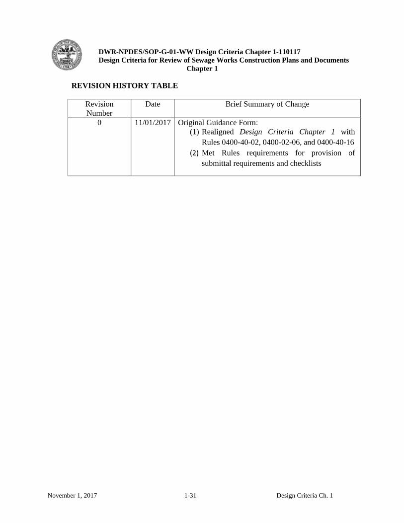
REVISION HISTORY TABLE
Revision Number
Date Brief Summary of Change
0 11/01/2017 Original Guidance Form: (1) Realigned Design Criteria Chapter 1 with
Rules 0400-40-02, 0400-02-06, and 0400-40-16 (2) Met Rules requirements for provision of
submittal requirements and checklists

DWR-NPDES/SOP-G-01-WW Design Criteria Chapter 1-110117 Design Criteria for Review of Sewage Works Construction Plans and Documents
Chapter 1
November 1, 2017 1-32 Design Criteria Ch. 1
THIS PAGE INTENTIONALLY LEFT BLANK
DWR-NPDES/SOP-G-01-WW Design Criteria Chapter 1-110117 Design Criteria for Review of Sewage Works Construction Plans and Documents
Chapter 1
Appendix 1-A
Current Emphasis in this Revision of the Design Criteria
The Mission of the Department of Environment and Conservation (TDEC) is to enhance the quality of life for citizens of Tennessee and to be stewards of our natural environment by protecting and promoting public health and safety, and protecting and improving the quality of Tennessee’s water through a responsible regulatory system. The Division of Water Resources has been delegated the responsibility to promulgate guidance for the review of engineering reports and plans for public, private and industrial wastewater facilities’ design, construction and acceptance of these works in support of the TDEC Mission.1 I. Overall Objectives:
a. Engineering planning and design should be supported by adequate data, sound scientific investigation and competent engineering to inform prudent decision-making in the planning and construction of treatment and conveyance projects. Evidence of a proposed solution’s ability to meet permit standards should be provided early in the design process to the owner and the Division prior to extensive consideration and detailed design. Regardless of the review process and the Criteria, the design agent remains principally responsible for the design, procurement, construction and efficacy of the design.
b. Sewage works should reflect as a paramount consideration: (1.) the impact on public health of the community and neighbors of the facility; (2.) the safety of operators; and (3.) due regard for the protection of equipment comprising the facility.
c. Design processes should: (1.) minimize destruction of natural resources, in particular, with respect to riparian environments, and surface and groundwater assets; (2.) reduce the discharge of nutrients consistent with facilities’ capabilities since there are frequently operational savings to be realized and unintended consequences to water quality downstream and; (3.) analyze reasonable project alternatives considering Life Cycle Cost Analyses for the expected life of the system and avoid dependence on initial capital costs alone.
d. Designs and planning that considers the preservation of wastewater infrastructure assets and their management is expected of all engineering endeavors. Engineers’ cost analyses and predictions are pivotal in predicting funding requirements for routine maintenance, in calculating depreciation for capital improvements for system sustainability and in determining the level of investment in the utility’s workforce to operate and maintain the systems that they design.
II. Design considerations prior to construction projects: a. In the case of aging infrastructure it is Division’s policy to encourage accurate comparison of
repair efforts, rehabilitation benefits, and replacement costs, to construction of new infrastructure.
1 Rules TDEC-DWR Section 0400-40-02-.03-(1)(effective December 16, 2013)

DWR-NPDES/SOP-G-01-WW Design Criteria Chapter 1-110117 Design Criteria for Review of Sewage Works Construction Plans and Documents
Chapter 1
b. In the case of service area growth and diversification of waste load, the accurate prediction of capacity needs and evaluation of waste characteristics should be investigated, documented and their impact considered.
c. When science indicates more stringent permit requirements to protect the environment are warranted, designs should provide realistic comparisons of:
i. the options for existing system optimization; ii. the benefits and drawbacks of new or modified facilities; and
iii. the options of relocation of discharges or dispersal areas, and redirection of discharges to land application or beneficial reuse.
III. Treatment
a. Waste load characterization used for design calculations should be realistic. Low current flows, current wet weather flows, wet weather flows at 80% of design flow and design flow (maximum average monthly flow) conditions should be examined as appropriate. The impact of expected constituent changes and unbuffered daily and seasonal flow patterns may be important as well. The use of actual data when there is an opportunity for its collection is always preferred over forecasted typical values from reference literature.
b. Unless there are unique circumstances or the potential for significant savings or effectiveness, generally proven straightforward technologies and processes should be given preference over new and unproven unless there is adequate justification.
c. The previous paragraph notwithstanding, the TDEC encourages the implementation of technologies new to Tennessee or new concepts. Evaluation of these potential advancements should consider:
i. Demonstrated operability, and predictability of the processes; provision of controls, as well as, the process visibility through adequate installed instrumentation to facilitate process control and optimization;
ii. Demonstrated achievement of its objectives over the expected range of flow and loads;
iii. Demonstrated maintainability and sustainability of the system in similar circumstances;
iv. Demonstrated efficiency and flexibility of the system considering often overlooked expenses such as manpower requirements (including operator skill and experience levels), maintainability, technical assistance and biosolids/residuals generation and handling. Consideration of operator skill level and instrumentation is particularly important if plant compliance is dependent on process optimization, and;
v. Demonstrated pilot plant performance on site with actual process flows. d. In most cases planning should include the consideration for expandability due to growth in
volume or diversity of influent characteristics (flow patterns, constituents, etc.) over time. e. Both the Division and USEPA believe that many secondary treatment plants can benefit from
incorporating denitrification in the design of new and in the optimization of existing secondary plants. There appear to be direct financial benefits as well as environmental benefits of simple biological nitrogen reduction.
DWR-NPDES/SOP-G-01-WW Design Criteria Chapter 1-110117 Design Criteria for Review of Sewage Works Construction Plans and Documents
Chapter 1
f. The Division endeavors to partner with academic institutions, utility and municipality organizations, equipment vendors and consulting engineering design firms to increase the education, knowledge base and skills of operators of the State’s treatment facilities.
IV. Collection Systems: a. Gravity Sewers: The lack of watertight integrity in gravity collection systems potentially
represents the largest avoidable financial burden to Tennessee wastewater utilities. Project evaluations should consider the long term consequences during selection of the quality of materials and installation methods, as well as, the financial impact of future capacity increases either through upgrading lines, adding equalization or increasing treatment plant hydraulic capacity instead of performing cost effective levels of sewer rehabilitation. Frequent wastewater flow monitoring correlated with local precipitation magnitude is considered necessary for a system to manage its gravity collection system capacity, determine the scope and location of repairs and measure the effectiveness of rehab and replacement efforts.
b. Sewer Lift Stations i. Adequate provision for the safe maintenance of sewer lift stations is of critical
importance. Lighting, adequate operation and maintenance access, lifting devices, explosive protection and reduction of the risk associated with confined space entry should be considered.
ii. Depending on the location of the station instrumentation may be an important consideration; run time meters, motor voltage and current meters, telemetry for failure response, level measurement beyond float control and level trending, flow meters and recorded flow histories are important diagnostic tools for the station and the sewer basin upstream of the station and may be more cost effective than additional temporary flow measuring devices.
iii. Controls and pump configurations such as variable frequency (speed) drives could improve the efficiency of the station, and reduce overflows and pumping costs.
c. Collection System Management. The Capacity Management, Operations and Maintenance (CMOM) program embodies the important aspects of collection system asset management and its implementation at appropriate levels considering the size and complexity of systems is universally encouraged; engineering investigations utilizing sound scientific and mathematical methods, design of capital improvements and long term cost effective allocation of utility resources represent the foundation of the CMOM program.
V. Disposal Options: Discharge, Dispersal, Reuse. a. Tennessee State law charges TDEC and DWR to incentivize land application and beneficial
reuse of reclaimed wastewater as an alternative to direct discharges to surface waters unless there is a detrimental effect on stream flow.
b. Land application of treated wastewater depends on the performance of treatment within the qualified soil areas to achieve adequate treatment before the remaining treated effluent constituents are returned to the waters of the state. As such the hydraulic and in situ
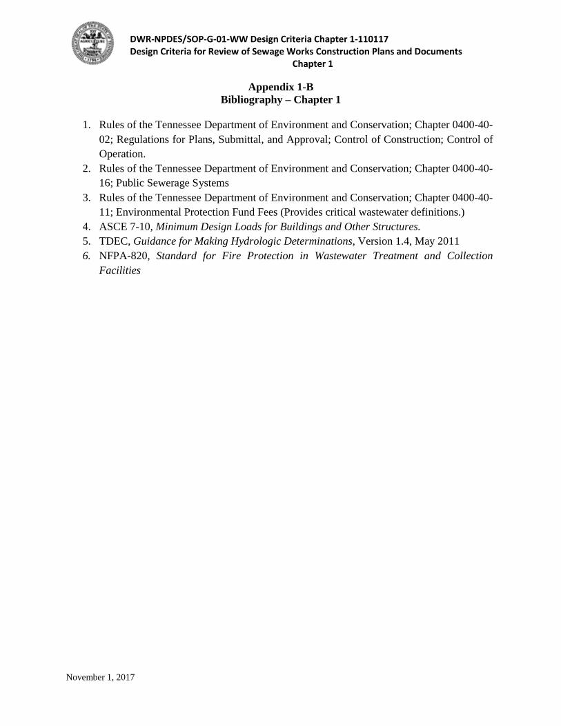
DWR-NPDES/SOP-G-01-WW Design Criteria Chapter 1-110117 Design Criteria for Review of Sewage Works Construction Plans and Documents
Chapter 1
November 1, 2017
Appendix 1-B Bibliography – Chapter 1
1. Rules of the Tennessee Department of Environment and Conservation; Chapter 0400-40-
02; Regulations for Plans, Submittal, and Approval; Control of Construction; Control of Operation.
2. Rules of the Tennessee Department of Environment and Conservation; Chapter 0400-40-16; Public Sewerage Systems
3. Rules of the Tennessee Department of Environment and Conservation; Chapter 0400-40-11; Environmental Protection Fund Fees (Provides critical wastewater definitions.)
4. ASCE 7-10, Minimum Design Loads for Buildings and Other Structures. 5. TDEC, Guidance for Making Hydrologic Determinations, Version 1.4, May 2011 6. NFPA-820, Standard for Fire Protection in Wastewater Treatment and Collection
Facilities

DWR-NPDES/SOP-G-01-WW Design Criteria Chapter 1-110117 Design Criteria for Review of Sewage Works Construction Plans and Documents
Chapter 1
November 1, 2017
THIS PAGE INTENTIONALLY LEFT BLANK
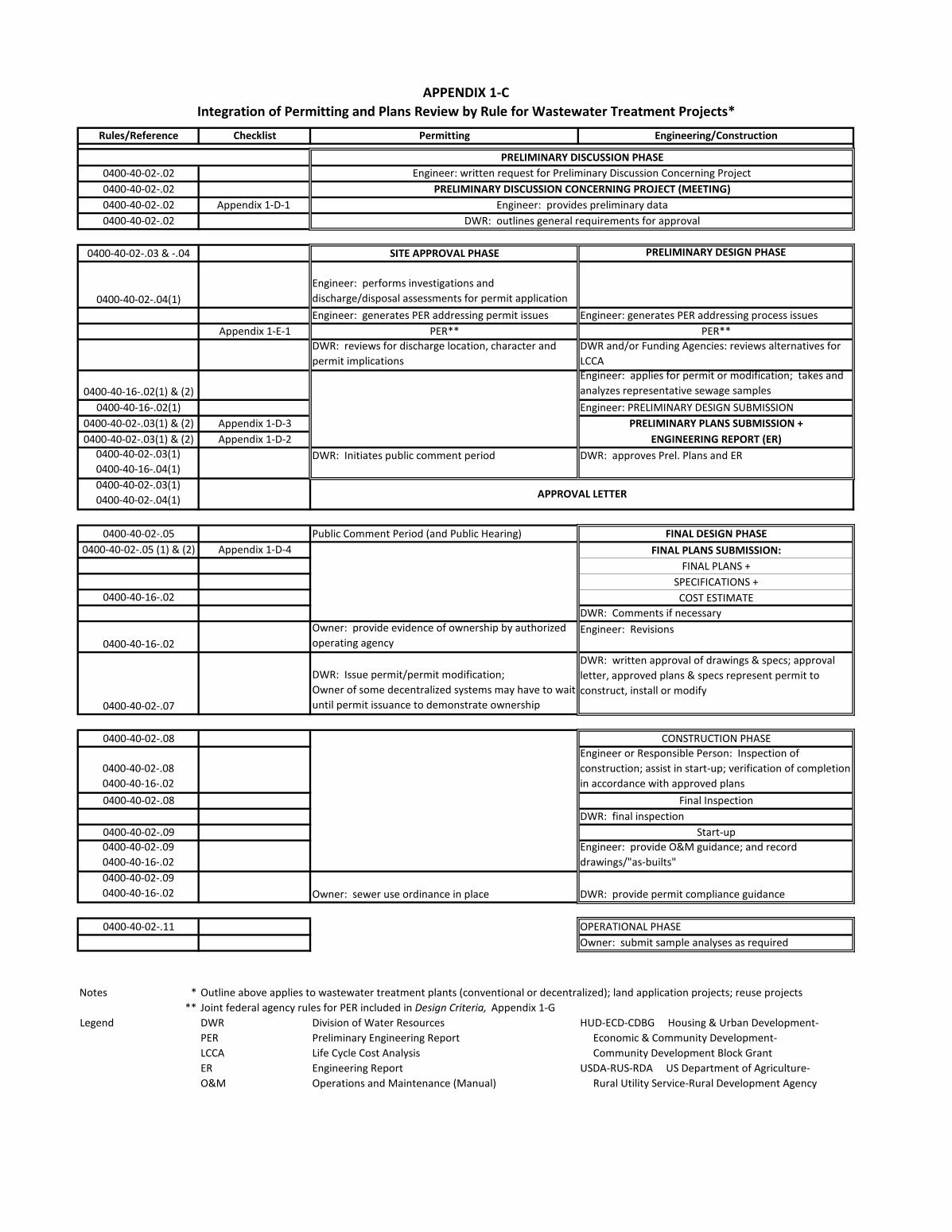
Rules/Reference Checklist Permitting Engineering/Construction
0400-40-02-.020400-40-02-.020400-40-02-.02 Appendix 1-D-1 0400-40-02-.02
0400-40-02-.03 & -.04 SITE APPROVAL PHASE PRELIMINARY DESIGN PHASE
0400-40-02-.04(1)Engineer: performs investigations and discharge/disposal assessments for permit applicationEngineer: generates PER addressing permit issues Engineer: generates PER addressing process issues
Appendix 1-E-1 PER** PER**DWR: reviews for discharge location, character and permit implications
DWR and/or Funding Agencies: reviews alternatives for LCCA
0400-40-16-.02(1) & (2)Engineer: applies for permit or modification; takes and analyzes representative sewage samples
0400-40-16-.02(1) Engineer: PRELIMINARY DESIGN SUBMISSION0400-40-02-.03(1) & (2) Appendix 1-D-3 PRELIMINARY PLANS SUBMISSION +0400-40-02-.03(1) & (2) Appendix 1-D-2 ENGINEERING REPORT (ER)
0400-40-02-.03(1) 0400-40-16-.04(1)
DWR: Initiates public comment period DWR: approves Prel. Plans and ER
0400-40-02-.03(1) 0400-40-02-.04(1)
0400-40-02-.05 Public Comment Period (and Public Hearing) FINAL DESIGN PHASE0400-40-02-.05 (1) & (2) Appendix 1-D-4 FINAL PLANS SUBMISSION:
FINAL PLANS +SPECIFICATIONS +
0400-40-16-.02 COST ESTIMATEDWR: Comments if necessary
0400-40-16-.02Owner: provide evidence of ownership by authorized operating agency
Engineer: Revisions
0400-40-02-.07
DWR: Issue permit/permit modification; Owner of some decentralized systems may have to wait until permit issuance to demonstrate ownership
DWR: written approval of drawings & specs; approval letter, approved plans & specs represent permit to construct, install or modify
0400-40-02-.08 CONSTRUCTION PHASE
0400-40-02-.08 0400-40-16-.02
Engineer or Responsible Person: Inspection of construction; assist in start-up; verification of completion in accordance with approved plans
0400-40-02-.08 Final InspectionDWR: final inspection
0400-40-02-.09 Start-up0400-40-02-.09 0400-40-16-.02
Engineer: provide O&M guidance; and record drawings/"as-builts"
0400-40-02-.09 0400-40-16-.02 Owner: sewer use ordinance in place DWR: provide permit compliance guidance
0400-40-02-.11 OPERATIONAL PHASEOwner: submit sample analyses as required
Notes ***
Legend DWR Division of Water Resources HUD-ECD-CDBG Housing & Urban Development-PER Preliminary Engineering Report Economic & Community Development-LCCA Life Cycle Cost Analysis Community Development Block GrantER Engineering Report USDA-RUS-RDA US Department of Agriculture-O&M Operations and Maintenance (Manual) Rural Utility Service-Rural Development Agency
APPENDIX 1-C
Outline above applies to wastewater treatment plants (conventional or decentralized); land application projects; reuse projectsJoint federal agency rules for PER included in Design Criteria, Appendix 1-G
Integration of Permitting and Plans Review by Rule for Wastewater Treatment Projects*
PRELIMINARY DISCUSSION CONCERNING PROJECT (MEETING)Engineer: provides preliminary data
DWR: outlines general requirements for approval
APPROVAL LETTER
PRELIMINARY DISCUSSION PHASEEngineer: written request for Preliminary Discussion Concerning Project

Discharge/disposal alternatives Process alternative analyses analyses --> permit application based on life cycle cost analyses
Eng/Owner--> DWR: Permit Application
Engineer-->DWR:
Engineer--> DWR
DWR: Comments address in
Eng-->DWR Requests const. permits
Eng & DWR: Monitoring & inspection
DWR & Eng: START UP
DWR & Eng: COMMISSIONING
DWR & Eng: FINAL INSPECTION
Eng-->DWR: Record drawings
DWR-->Owner/Eng: Construction docs approved
permit rationale
NPDES Permit issued
DWR: Construction permits issued
PRELIMINARY DISCUSSION CONCERNING PROJECT
DWR: Permit on public notice
Public Comment Period closesDWR: Public comments addressed
SpecificationsCost Estimate
Engineering Report Changes
Final Engineering Plans
PRELIMINARY DISCUSSION PHASE
DWR-->Owner/Engineer: APPROVAL LETTER ISSUED
Engineer/Owner collects data and requests meeting
DWR-->Owner/Eng: Preliminary Discussion Minutes
DWR: Review PERDWR: Approve PER
DWR: Permit Drafted
SITE APPROVAL PHASE
Engineer-->DWR: PER Engineer-->DWR: PER
November 1, 2017
Treatment (TF, DC, IW, LA) Projects (See Appendix 1-D-1 for project type definitions)
Appendix 1-C-1
PERMITTING PLANS REVIEW/CONSTRUCTION
PRELIMINARY ENGINEERING PHASE
Preliminary PlansEngineering Report
FINAL DESIGN PHASE
CONSTRUCTION PHASE
Owner/Eng: PROJECT BID
Owner/Eng: PROJECT AWARDED
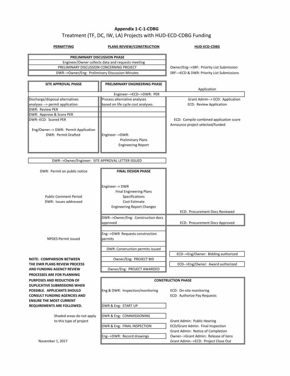
Discharge/disposal alternatives Process alternative analyses Grant Admin--> ECD: Applicationanalyses --> permit application based on life cycle cost analyses.DWR: Review PERDWR: Approve & Score PERDWR--ECD: Scored PER
Announce project selected/funded
Engineer-->DWR:
Engineer--> DWR
NOTE: COMPARISON BETWEENTHE DWR PLANS REVIEW PROCESS AND FUNDING AGENCY REVIEWPROCESSES ARE FOR PLANNING PURPOSES AND REDUCTION OF DUPLICATIVE SUBMISSIONS WHENPOSSIBLE. APPLICANTS SHOULD Eng & DWR: Inspection/monitoring ECD: On-site monitoringCONSULT FUNDING AGENCIES AND ECD: Authorize Pay RequestsENSURE THE MOST CURRENT REQUIREMENTS ARE FOLLOWED. DWR & Eng: START UP
DWR & Eng: COMMISSIONING
DWR & Eng: FINAL INSPECTION
Eng-->DWR: Record drawings Grant Admin-->ECD: Project Close Out
Shaded areas do not apply to this type of project
Owner-->Grant Admin: Release of liens
ECD: Procurement Docs Reviewed
ECD-->Eng/Owner: Bidding authorized
ECD-->Eng/Owner: Award authorized
ECD: Procurement Docs Approved
DWR: Permit Drafted
PERMITTING PLANS REVIEW/CONSTRUCTION
ECD/Grant Admin: Final InspectionGrant Admin: Notice of Completion
PRELIMINARY ENGINEERING PHASE
Preliminary PlansEngineering Report
FINAL DESIGN PHASE
Owner/Eng: PROJECT BID
Owner/Eng: PROJECT AWARDED
SpecificationsCost Estimate
Application
Treatment (TF, DC, IW, LA) Projects with HUD-ECD-CDBG FundingAppendix 1-C-1-CDBG
HUD-ECD-CDBG
Owner/Eng-->SRF: Priority List SubmissionSRF-->ECD & DWR: Priority List Submissions
ECD: Compile combined application score
Engineering Report Changes
Final Engineering Plans
CONSTRUCTION PHASE
Grant Admin: Public Hearing
DWR-->Owner/Eng: Construction docs approved
Eng-->DWR Requests construction permits
November 1, 2017
NPDES Permit issued
DWR: Construction permits issued
PRELIMINARY DISCUSSION CONCERNING PROJECT
PRELIMINARY DISCUSSION PHASE
DWR-->Owner/Engineer: SITE APPROVAL LETTER ISSUED
Engineer/Owner collects data and requests meeting
DWR-->Owner/Eng: Preliminary Discussion Minutes
Eng/Owner--> DWR: Permit Application
DWR: Permit on public notice
SITE APPROVAL PHASE
Public Comment PeriodDWR: Issues addressed
Engineer-->ECD-->DWR: PER
ECD: Review Application
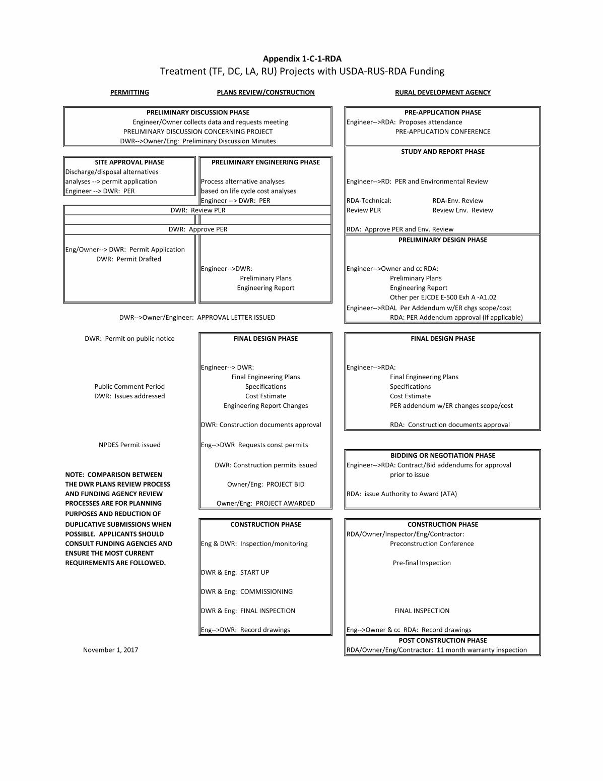
Engineer-->RDA: Proposes attendance
Discharge/disposal alternativesanalyses --> permit application Process alternative analyses Engineer-->RD: PER and Environmental ReviewEngineer --> DWR: PER based on life cycle cost analyses
Engineer --> DWR: PER RDA-Technical: RDA-Env. ReviewReview PER Review Env. Review
RDA: Approve PER and Env. Review
Eng/Owner--> DWR: Permit Application
Engineer-->DWR: Engineer-->Owner and cc RDA:Preliminary PlansEngineering Report Other per EJCDE E-500 Exh A -A1.02
Engineer-->RDAL Per Addendum w/ER chgs scope/costRDA: PER Addendum approval (if applicable)
Engineer--> DWR: Engineer-->RDA:Final Engineering PlansSpecificationsCost EstimatePER addendum w/ER changes scope/cost
DWR: Construction documents approval RDA: Construction documents approval
Eng-->DWR Requests const permits
Engineer-->RDA: Contract/Bid addendums for approval NOTE: COMPARISON BETWEEN prior to issueTHE DWR PLANS REVIEW PROCESS AND FUNDING AGENCY REVIEW RDA: issue Authority to Award (ATA)PROCESSES ARE FOR PLANNING PURPOSES AND REDUCTION OF DUPLICATIVE SUBMISSIONS WHENPOSSIBLE. APPLICANTS SHOULD RDA/Owner/Inspector/Eng/Contractor: CONSULT FUNDING AGENCIES AND Eng & DWR: Inspection/monitoring Preconstruction ConferenceENSURE THE MOST CURRENT REQUIREMENTS ARE FOLLOWED. Pre-final Inspection
DWR & Eng: START UP
DWR & Eng: COMMISSIONING
DWR & Eng: FINAL INSPECTION FINAL INSPECTION
Eng-->DWR: Record drawings Eng-->Owner & cc RDA: Record drawings
RDA/Owner/Eng/Contractor: 11 month warranty inspection
CONSTRUCTION PHASE
BIDDING OR NEGOTIATION PHASE
PRELIMINARY DESIGN PHASE
FINAL DESIGN PHASE
POST CONSTRUCTION PHASE
NPDES Permit issued
DWR: Construction permits issued
DWR: Permit on public notice
Public Comment Period
FINAL DESIGN PHASE
CONSTRUCTION PHASE
Owner/Eng: PROJECT BID
Appendix 1-C-1-RDA
Owner/Eng: PROJECT AWARDED
SpecificationsCost Estimate
Engineering Report Changes
Final Engineering Plans
PRELIMINARY DISCUSSION CONCERNING PROJECT
PRELIMINARY DISCUSSION PHASE
DWR-->Owner/Engineer: APPROVAL LETTER ISSUED
Engineer/Owner collects data and requests meeting
DWR-->Owner/Eng: Preliminary Discussion Minutes
DWR: Review PER
DWR: Approve PER
DWR: Permit Drafted
DWR: Issues addressed
Treatment (TF, DC, LA, RU) Projects with USDA-RUS-RDA Funding
PERMITTING PLANS REVIEW/CONSTRUCTION RURAL DEVELOPMENT AGENCY
PRE-APPLICATION PHASE
PRE-APPLICATION CONFERENCE
STUDY AND REPORT PHASE
November 1, 2017
SITE APPROVAL PHASE PRELIMINARY ENGINEERING PHASE
Preliminary PlansEngineering Report
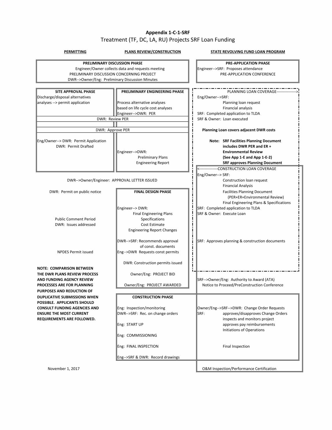
Engineer-->SRF: Proposes attendance
Discharge/disposal alternatives Eng/Owner-->SRF: Planning loan request
based on life cycle cost analyses Financial analysisEngineer-->DWR: PER SRF: Completed application to TLDA
SRF & Owner: Loan executed
Planning Loan covers adjacent DWR costs
Eng/Owner--> DWR: Permit Application Note: SRF Facilities Planning Documentincludes DWR PER and ER +
Engineer-->DWR: Environmental Review (See App 1-E and App 1-E-2)
SRF approves Planning Document
Eng/Owner--> SRF: Construction loan requestFinancial AnalysisFacilities Planning Document (PER+ER+Environmental Review)Final Engineering Plans & Specifications
Engineer--> DWR: SRF: Completed application to TLDASRF & Owner: Execute Loan
DWR-->SRF: Recommends approval SRF: Approves planning & construction documentsof const. documents
Eng-->DWR Requests const permits
NOTE: COMPARISON BETWEENTHE DWR PLANS REVIEW PROCESS AND FUNDING AGENCY REVIEW SRF-->Owner/Eng: Authority to Award (ATA)PROCESSES ARE FOR PLANNING Notice to Proceed/PreConstruction ConferencePURPOSES AND REDUCTION OF DUPLICATIVE SUBMISSIONS WHENPOSSIBLE. APPLICANTS SHOULDCONSULT FUNDING AGENCIES AND Eng: Inspection/monitoring Owner/Eng-->SRF-->DWR: Change Order RequestsENSURE THE MOST CURRENT DWR-->SRF: Rec. on change orders SRF: approves/disapproves Change OrdersREQUIREMENTS ARE FOLLOWED. inspects and monitors project
Eng: START UP approves pay reimbursementsInitiations of Operations
Eng: COMMISSIONING
Eng: FINAL INSPECTION Final Inspection
Eng-->SRF & DWR: Record drawings
O&M Inspection/Performance Certification
NPDES Permit issued
DWR: Construction permits issued
DWR: Permit on public notice
Public Comment Period
FINAL DESIGN PHASE
CONSTRUCTION PHASE
Owner/Eng: PROJECT BID
DWR: Issues addressed
Appendix 1-C-1-SRF
Owner/Eng: PROJECT AWARDED
SpecificationsCost Estimate
Engineering Report Changes
Final Engineering Plans
PRELIMINARY DISCUSSION CONCERNING PROJECT
PRELIMINARY DISCUSSION PHASE
DWR-->Owner/Engineer: APPROVAL LETTER ISSUED
Engineer/Owner collects data and requests meeting
DWR-->Owner/Eng: Preliminary Discussion Minutes
analyses --> permit application Process alternative analyses
DWR: Review PER
DWR: Approve PER
DWR: Permit Drafted
Treatment (TF, DC, LA, RU) Projects SRF Loan Funding
PERMITTING PLANS REVIEW/CONSTRUCTION STATE REVOLVING FUND LOAN PROGRAM
PRE-APPLICATION PHASE
November 1, 2017
Engineering Report
PLANNING LOAN COVERAGE--------------->
PRE-APPLICATION CONFERENCE
SITE APPROVAL PHASE PRELIMINARY ENGINEERING PHASE
Preliminary Plans
<--------------CONSTRUCTION LOAN COVERAGE
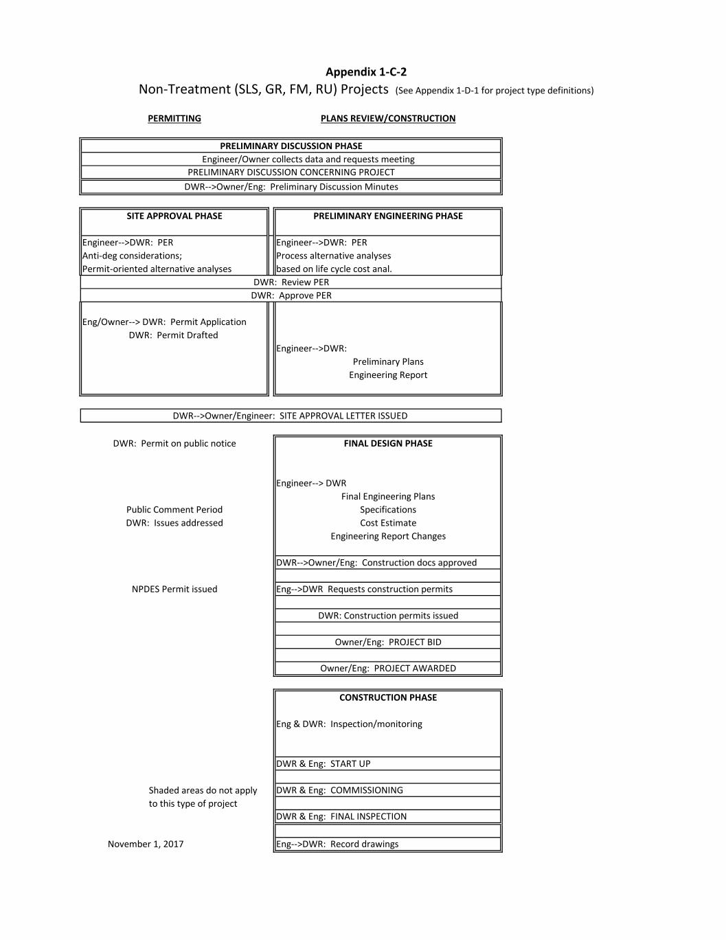
Anti-deg considerations; Process alternative analyses Permit-oriented alternative analyses based on life cycle cost anal.
Eng/Owner--> DWR: Permit Application
Engineer-->DWR:
Engineer--> DWR
DWR-->Owner/Eng: Construction docs approved
Eng-->DWR Requests construction permits
Eng & DWR: Inspection/monitoring
DWR & Eng: START UP
DWR & Eng: COMMISSIONING
DWR & Eng: FINAL INSPECTION
Eng-->DWR: Record drawings
FINAL DESIGN PHASE
CONSTRUCTION PHASE
Owner/Eng: PROJECT BID
Non-Treatment (SLS, GR, FM, RU) Projects (See Appendix 1-D-1 for project type definitions)
Appendix 1-C-2
PERMITTING PLANS REVIEW/CONSTRUCTION
DWR: Issues addressed
November 1, 2017
NPDES Permit issued
DWR: Construction permits issued
PRELIMINARY DISCUSSION CONCERNING PROJECT
DWR: Permit on public notice
Owner/Eng: PROJECT AWARDED
SpecificationsCost Estimate
Engineering Report Changes
Final Engineering Plans
Shaded areas do not apply to this type of project
Public Comment Period
PRELIMINARY DISCUSSION PHASE
DWR-->Owner/Engineer: SITE APPROVAL LETTER ISSUED
Engineer/Owner collects data and requests meeting
DWR-->Owner/Eng: Preliminary Discussion Minutes
Engineer-->DWR: PER Engineer-->DWR: PER
DWR: Review PERDWR: Approve PER
DWR: Permit Drafted
SITE APPROVAL PHASE PRELIMINARY ENGINEERING PHASE
Preliminary PlansEngineering Report
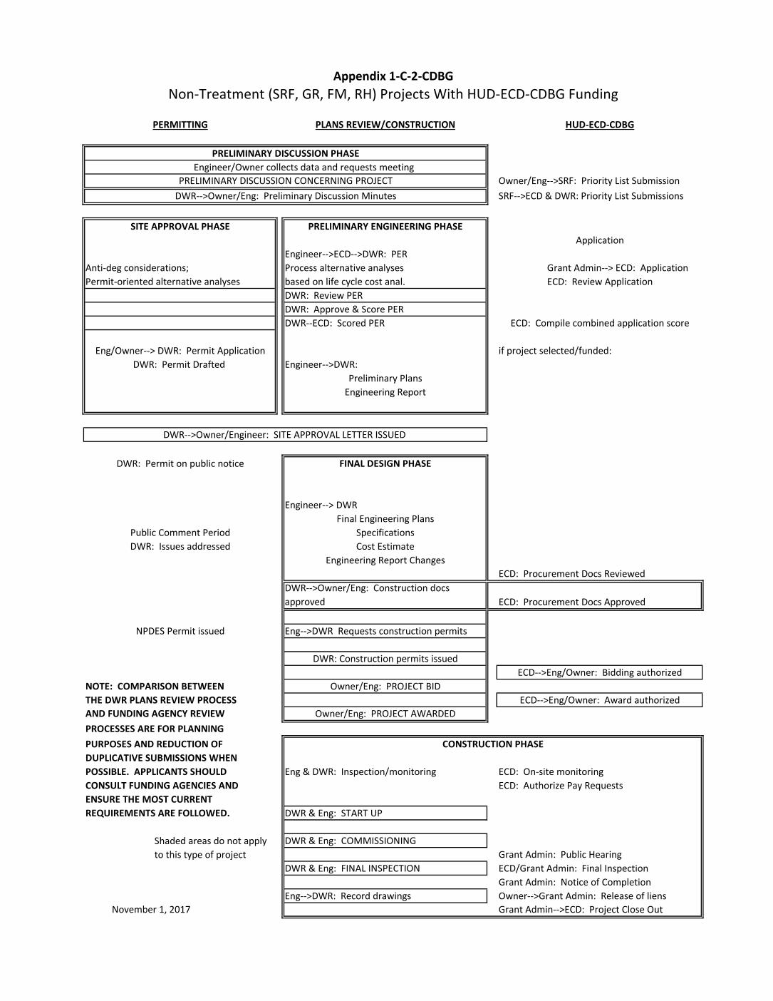
Engineer-->ECD-->DWR: PERAnti-deg considerations; Process alternative analyses Grant Admin--> ECD: ApplicationPermit-oriented alternative analyses based on life cycle cost anal.
DWR: Review PERDWR: Approve & Score PERDWR--ECD: Scored PER
if project selected/funded:Engineer-->DWR:
Engineer--> DWR
Eng-->DWR Requests construction permits
NOTE: COMPARISON BETWEENTHE DWR PLANS REVIEW PROCESS AND FUNDING AGENCY REVIEWPROCESSES ARE FOR PLANNING PURPOSES AND REDUCTION OF DUPLICATIVE SUBMISSIONS WHENPOSSIBLE. APPLICANTS SHOULD Eng & DWR: Inspection/monitoring ECD: On-site monitoringCONSULT FUNDING AGENCIES AND ECD: Authorize Pay RequestsENSURE THE MOST CURRENT REQUIREMENTS ARE FOLLOWED. DWR & Eng: START UP
DWR & Eng: COMMISSIONING
DWR & Eng: FINAL INSPECTION
Eng-->DWR: Record drawings Grant Admin-->ECD: Project Close Out
NPDES Permit issued
Owner/Eng: PROJECT BID
Owner/Eng: PROJECT AWARDED
DWR: Construction permits issued
DWR: Permit Drafted
DWR: Issues addressed
DWR-->Owner/Eng: Construction docs approved
Preliminary PlansEngineering Report
ECD-->Eng/Owner: Bidding authorized
ECD-->Eng/Owner: Award authorized
ECD: Review Application
ECD: Compile combined application score
CONSTRUCTION PHASE
ECD: Procurement Docs Approved
November 1, 2017
ECD/Grant Admin: Final InspectionGrant Admin: Notice of CompletionOwner-->Grant Admin: Release of liens
Grant Admin: Public HearingShaded areas do not apply to this type of project
PRELIMINARY DISCUSSION PHASE Engineer/Owner collects data and requests meeting
DWR-->Owner/Eng: Preliminary Discussion Minutes
Eng/Owner--> DWR: Permit Application
ECD: Procurement Docs Reviewed
Owner/Eng-->SRF: Priority List SubmissionSRF-->ECD & DWR: Priority List Submissions
PRELIMINARY ENGINEERING PHASEApplication
PRELIMINARY DISCUSSION CONCERNING PROJECT
SpecificationsCost Estimate
Engineering Report Changes
SITE APPROVAL PHASE
Public Comment Period
PERMITTING PLANS REVIEW/CONSTRUCTION
Non-Treatment (SRF, GR, FM, RH) Projects With HUD-ECD-CDBG FundingAppendix 1-C-2-CDBG
HUD-ECD-CDBG
FINAL DESIGN PHASE
Final Engineering Plans
DWR-->Owner/Engineer: SITE APPROVAL LETTER ISSUED
DWR: Permit on public notice
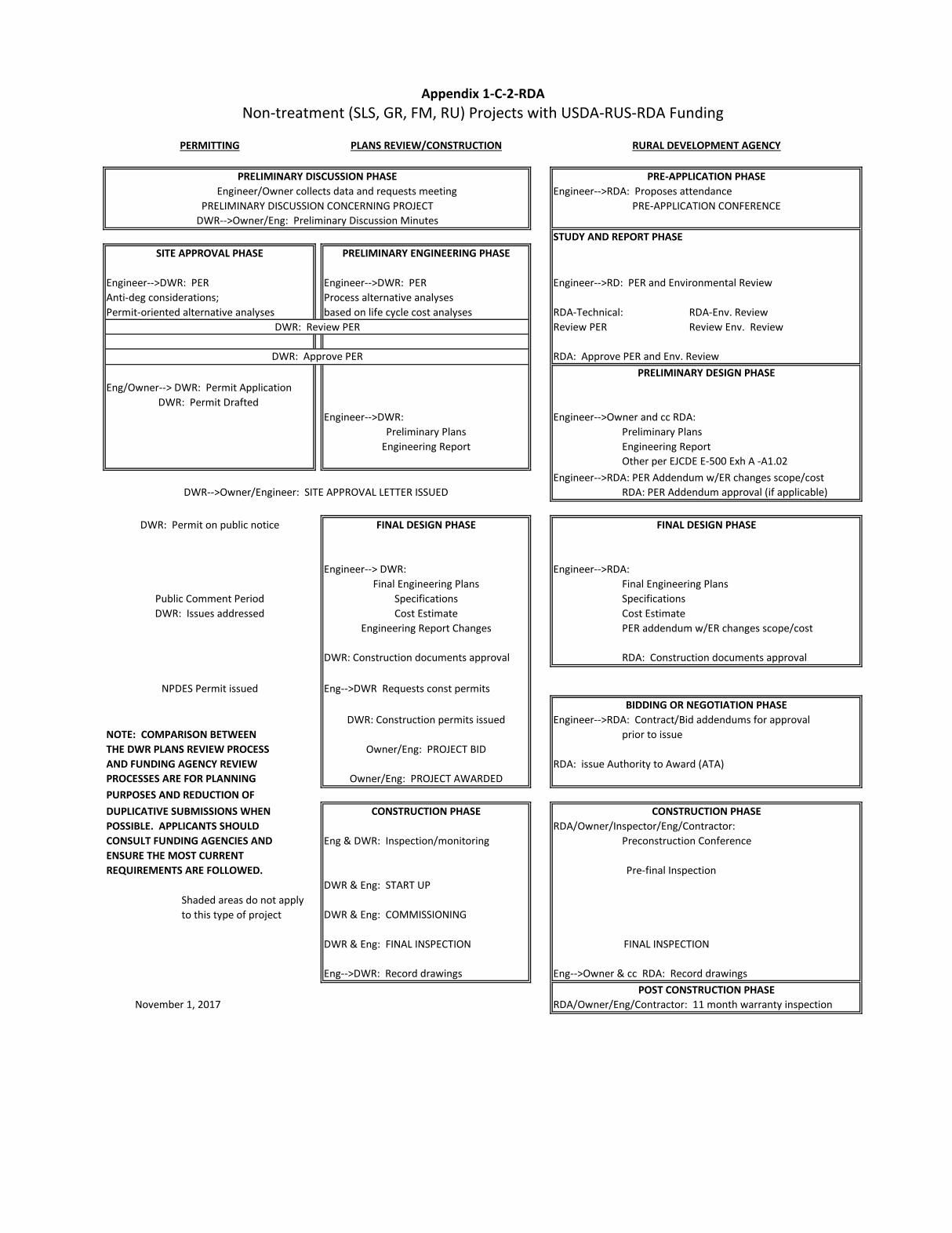
Engineer-->RDA: Proposes attendance
STUDY AND REPORT PHASE
Engineer-->RD: PER and Environmental ReviewAnti-deg considerations; Process alternative analyses Permit-oriented alternative analyses based on life cycle cost analyses RDA-Technical: RDA-Env. Review
Review PER Review Env. Review
RDA: Approve PER and Env. Review
Eng/Owner--> DWR: Permit Application
Engineer-->DWR: Engineer-->Owner and cc RDA:Preliminary PlansEngineering Report Other per EJCDE E-500 Exh A -A1.02
Engineer-->RDA: PER Addendum w/ER changes scope/costRDA: PER Addendum approval (if applicable)
Engineer--> DWR: Engineer-->RDA:Final Engineering PlansSpecificationsCost EstimatePER addendum w/ER changes scope/cost
DWR: Construction documents approval RDA: Construction documents approval
Eng-->DWR Requests const permits
Engineer-->RDA: Contract/Bid addendums for approvalNOTE: COMPARISON BETWEEN prior to issueTHE DWR PLANS REVIEW PROCESS AND FUNDING AGENCY REVIEW RDA: issue Authority to Award (ATA)PROCESSES ARE FOR PLANNING PURPOSES AND REDUCTION OF DUPLICATIVE SUBMISSIONS WHENPOSSIBLE. APPLICANTS SHOULD RDA/Owner/Inspector/Eng/Contractor: CONSULT FUNDING AGENCIES AND Eng & DWR: Inspection/monitoring Preconstruction ConferenceENSURE THE MOST CURRENT REQUIREMENTS ARE FOLLOWED. Pre-final Inspection
DWR & Eng: START UP
DWR & Eng: COMMISSIONING
DWR & Eng: FINAL INSPECTION FINAL INSPECTION
Eng-->DWR: Record drawings Eng-->Owner & cc RDA: Record drawings
RDA/Owner/Eng/Contractor: 11 month warranty inspection
Shaded areas do not apply to this type of project
DWR: Permit Drafted
DWR: Issues addressed
Non-treatment (SLS, GR, FM, RU) Projects with USDA-RUS-RDA Funding
PERMITTING PLANS REVIEW/CONSTRUCTION RURAL DEVELOPMENT AGENCY
PRE-APPLICATION PHASE
PRE-APPLICATION CONFERENCE
SITE APPROVAL PHASE PRELIMINARY ENGINEERING PHASE
Preliminary PlansEngineering Report
Owner/Eng: PROJECT BID
Appendix 1-C-2-RDA
Owner/Eng: PROJECT AWARDED
SpecificationsCost Estimate
Engineering Report Changes
Final Engineering Plans
PRELIMINARY DISCUSSION CONCERNING PROJECT
PRELIMINARY DISCUSSION PHASE
DWR-->Owner/Engineer: SITE APPROVAL LETTER ISSUED
Engineer/Owner collects data and requests meeting
DWR-->Owner/Eng: Preliminary Discussion Minutes
Engineer-->DWR: PER Engineer-->DWR: PER
DWR: Review PER
DWR: Approve PER
November 1, 2017
CONSTRUCTION PHASE
BIDDING OR NEGOTIATION PHASE
PRELIMINARY DESIGN PHASE
FINAL DESIGN PHASE
POST CONSTRUCTION PHASE
NPDES Permit issued
DWR: Construction permits issued
DWR: Permit on public notice
Public Comment Period
FINAL DESIGN PHASE
CONSTRUCTION PHASE
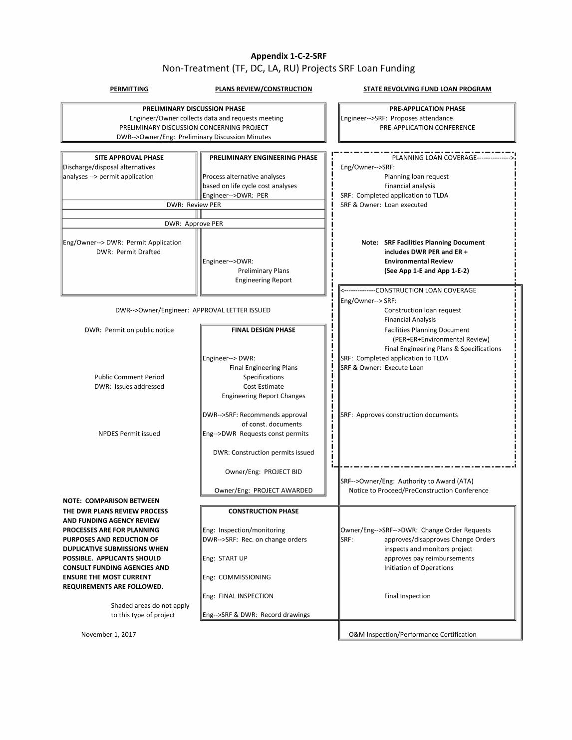
Engineer-->SRF: Proposes attendance
Discharge/disposal alternatives Eng/Owner-->SRF: Planning loan request
based on life cycle cost analyses Financial analysisEngineer-->DWR: PER SRF: Completed application to TLDA
SRF & Owner: Loan executed
Eng/Owner--> DWR: Permit Application Note: SRF Facilities Planning Documentincludes DWR PER and ER +
Engineer-->DWR: Environmental Review (See App 1-E and App 1-E-2)
Eng/Owner--> SRF: Construction loan requestFinancial AnalysisFacilities Planning Document (PER+ER+Environmental Review)Final Engineering Plans & Specifications
Engineer--> DWR: SRF: Completed application to TLDASRF & Owner: Execute Loan
DWR-->SRF: Recommends approval SRF: Approves construction documentsof const. documents
Eng-->DWR Requests const permits
SRF-->Owner/Eng: Authority to Award (ATA) Notice to Proceed/PreConstruction Conference
NOTE: COMPARISON BETWEENTHE DWR PLANS REVIEW PROCESS AND FUNDING AGENCY REVIEWPROCESSES ARE FOR PLANNING Eng: Inspection/monitoring Owner/Eng-->SRF-->DWR: Change Order RequestsPURPOSES AND REDUCTION OF DWR-->SRF: Rec. on change orders SRF: approves/disapproves Change OrdersDUPLICATIVE SUBMISSIONS WHEN inspects and monitors project POSSIBLE. APPLICANTS SHOULD Eng: START UP approves pay reimbursementsCONSULT FUNDING AGENCIES AND Initiation of OperationsENSURE THE MOST CURRENT Eng: COMMISSIONINGREQUIREMENTS ARE FOLLOWED.
Eng: FINAL INSPECTION Final Inspection
Eng-->SRF & DWR: Record drawings
O&M Inspection/Performance Certification
PERMITTING PLANS REVIEW/CONSTRUCTION STATE REVOLVING FUND LOAN PROGRAM
PRE-APPLICATION PHASE
Shaded areas do not apply to this type of project
<--------------CONSTRUCTION LOAN COVERAGEEngineering Report
PLANNING LOAN COVERAGE--------------->
PRE-APPLICATION CONFERENCE
SITE APPROVAL PHASE PRELIMINARY ENGINEERING PHASE
Preliminary Plans
DWR: Permit Drafted
DWR: Issues addressed
Appendix 1-C-2-SRF
Owner/Eng: PROJECT AWARDED
SpecificationsCost Estimate
Engineering Report Changes
Final Engineering Plans
PRELIMINARY DISCUSSION CONCERNING PROJECT
PRELIMINARY DISCUSSION PHASE
DWR-->Owner/Engineer: APPROVAL LETTER ISSUED
Engineer/Owner collects data and requests meeting
DWR-->Owner/Eng: Preliminary Discussion Minutes
analyses --> permit application Process alternative analyses
DWR: Review PER
DWR: Approve PER
Non-Treatment (TF, DC, LA, RU) Projects SRF Loan Funding
November 1, 2017
NPDES Permit issued
DWR: Construction permits issued
DWR: Permit on public notice
Public Comment Period
FINAL DESIGN PHASE
CONSTRUCTION PHASE
Owner/Eng: PROJECT BID
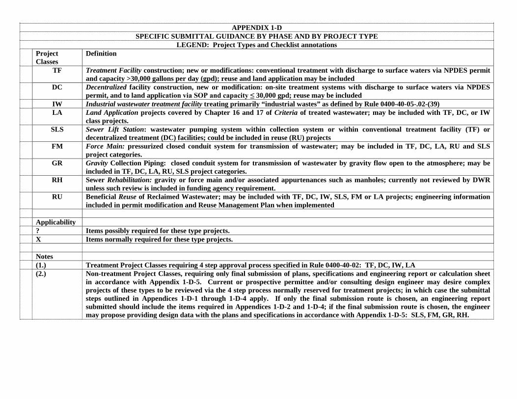
APPENDIX 1-D SPECIFIC SUBMITTAL GUIDANCE BY PHASE AND BY PROJECT TYPE
LEGEND: Project Types and Checklist annotations Project
Classes Definition
TF Treatment Facility construction; new or modifications: conventional treatment with discharge to surface waters via NPDES permit and capacity >30,000 gallons per day (gpd); reuse and land application may be included
DC Decentralized facility construction, new or modification: on-site treatment systems with discharge to surface waters via NPDES permit, and to land application via SOP and capacity ≤ 30,000 gpd; reuse may be included
IW Industrial wastewater treatment facility treating primarily “industrial wastes” as defined by Rule 0400-40-05-.02-(39) LA Land Application projects covered by Chapter 16 and 17 of Criteria of treated wastewater; may be included with TF, DC, or IW
class projects. SLS Sewer Lift Station: wastewater pumping system within collection system or within conventional treatment facility (TF) or
decentralized treatment (DC) facilities; could be included in reuse (RU) projects FM Force Main: pressurized closed conduit system for transmission of wastewater; may be included in TF, DC, LA, RU and SLS
project categories. GR Gravity Collection Piping: closed conduit system for transmission of wastewater by gravity flow open to the atmosphere; may be
included in TF, DC, LA, RU, SLS project categories. RH Sewer Rehabilitation: gravity or force main and/or associated appurtenances such as manholes; currently not reviewed by DWR
unless such review is included in funding agency requirement. RU Beneficial Reuse of Reclaimed Wastewater; may be included with TF, DC, IW, SLS, FM or LA projects; engineering information
included in permit modification and Reuse Management Plan when implemented Applicability ? Items possibly required for these type projects. X Items normally required for these type projects. Notes (1.) Treatment Project Classes requiring 4 step approval process specified in Rule 0400-40-02: TF, DC, IW, LA (2.) Non-treatment Project Classes, requiring only final submission of plans, specifications and engineering report or calculation sheet
in accordance with Appendix 1-D-5. Current or prospective permittee and/or consulting design engineer may desire complex projects of these types to be reviewed via the 4 step process normally reserved for treatment projects; in which case the submittal steps outlined in Appendices 1-D-1 through 1-D-4 apply. If only the final submission route is chosen, an engineering report submitted should include the items required in Appendices 1-D-2 and 1-D-4; if the final submission route is chosen, the engineer may propose providing design data with the plans and specifications in accordance with Appendix 1-D-5: SLS, FM, GR, RH.

THIS PAGE INTENTIONALLY LEFT BLANK
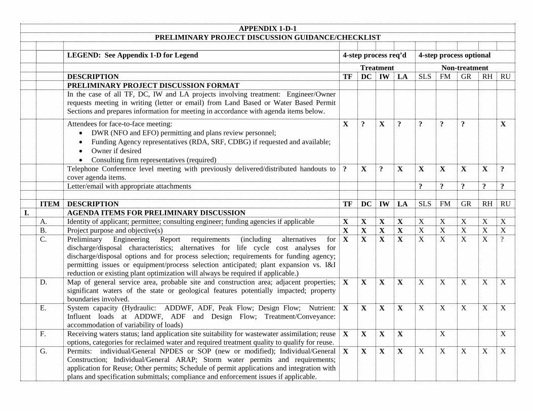
APPENDIX 1-D-1 PRELIMINARY PROJECT DISCUSSION GUIDANCE/CHECKLIST
LEGEND: See Appendix 1-D for Legend 4-step process req’d 4-step process optional
Treatment Non-treatment DESCRIPTION TF DC IW LA SLS FM GR RH RU PRELIMINARY PROJECT DISCUSSION FORMAT In the case of all TF, DC, IW and LA projects involving treatment: Engineer/Owner
requests meeting in writing (letter or email) from Land Based or Water Based Permit Sections and prepares information for meeting in accordance with agenda items below.
Attendees for face-to-face meeting: • DWR (NFO and EFO) permitting and plans review personnel; • Funding Agency representatives (RDA, SRF, CDBG) if requested and available; • Owner if desired • Consulting firm representatives (required)
X ? X ? ? ? ? X
Telephone Conference level meeting with previously delivered/distributed handouts to cover agenda items.
? X ? X X X X X ?
Letter/email with appropriate attachments ? ? ? ? ? ITEM DESCRIPTION TF DC IW LA SLS FM GR RH RU I. AGENDA ITEMS FOR PRELIMINARY DISCUSSION A. Identity of applicant; permittee; consulting engineer; funding agencies if applicable X X X X X X X X X B. Project purpose and objective(s) X X X X X X X X X C. Preliminary Engineering Report requirements (including alternatives for
discharge/disposal characteristics; alternatives for life cycle cost analyses for discharge/disposal options and for process selection; requirements for funding agency; permitting issues or equipment/process selection anticipated; plant expansion vs. I&I reduction or existing plant optimization will always be required if applicable.)
X X X X X X X X ?
D. Map of general service area, probable site and construction area; adjacent properties; significant waters of the state or geological features potentially impacted; property boundaries involved.
X X X X X X X X X
E. System capacity (Hydraulic: ADDWF, ADF, Peak Flow; Design Flow; Nutrient: Influent loads at ADDWF, ADF and Design Flow; Treatment/Conveyance: accommodation of variability of loads)
X X X X X X X X X
F. Receiving waters status; land application site suitability for wastewater assimilation; reuse options, categories for reclaimed water and required treatment quality to qualify for reuse.
X X X X X X
G. Permits: individual/General NPDES or SOP (new or modified); Individual/General Construction; Individual/General ARAP; Storm water permits and requirements; application for Reuse; Other permits; Schedule of permit applications and integration with plans and specification submittals; compliance and enforcement issues if applicable.
X X X X X X X X X
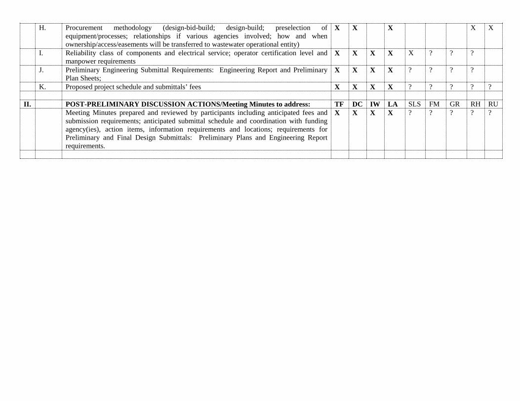
H. Procurement methodology (design-bid-build; design-build; preselection of equipment/processes; relationships if various agencies involved; how and when ownership/access/easements will be transferred to wastewater operational entity)
X X X X X
I. Reliability class of components and electrical service; operator certification level and manpower requirements
X X X X X ? ? ?
J. Preliminary Engineering Submittal Requirements: Engineering Report and Preliminary Plan Sheets;
X X X X ? ? ? ?
K. Proposed project schedule and submittals’ fees X X X X ? ? ? ? ? II. POST-PRELIMINARY DISCUSSION ACTIONS/Meeting Minutes to address: TF DC IW LA SLS FM GR RH RU Meeting Minutes prepared and reviewed by participants including anticipated fees and
submission requirements; anticipated submittal schedule and coordination with funding agency(ies), action items, information requirements and locations; requirements for Preliminary and Final Design Submittals: Preliminary Plans and Engineering Report requirements.
X X X X ? ? ? ? ?
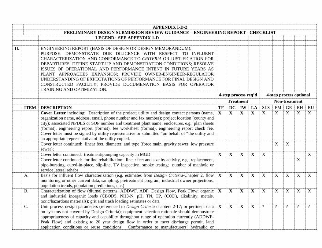
APPENDIX I-D-2 PRELIMINARY DESIGN SUBMISSION REVIEW GUIDANCE – ENGINEERING REPORT - CHECKLIST
LEGEND: SEE APPENDIX 1-D II. ENGINEERING REPORT (BASIS OF DESIGN OR DESIGN MEMORANDUM):
PURPOSE: DEMONSTRATE DUE DILIGENCE WITH RESPECT TO INFLUENT CHARACTERIZATION AND CONFORMANCE TO CRITERIA OR JUSTIFICATION FOR DEPARTURES; DEFINE START-UP AND DEMONSTRATION CONDITIONS; RESOLVE ISSUES OF OPERATIONAL AND PERFORMANCE INTENT IN FUTURE YEARS AS PLANT APPROACHES EXPANSION; PROVIDE OWNER-ENGINEER-REGULATOR UNDERSTANDING OF EXPECTATIONS OF PERFORMANCE FOR FINAL DESIGN AND CONSTRUCTED FACILITY; PROVIDE DOCUMENATION BASIS FOR OPERATOR TRAINING AND OPTIMIZATION.
4-step process req’d 4-step process optional Treatment Non-treatment ITEM DESCRIPTION TF DC IW LA SLS FM GR RH RU Cover Letter including: Description of the project; utility and design contact persons (name,
organization name, address, email, phone number and fax number); project location (county and city); associated NPDES or SOP number and treatment plant name; enclosures, e.g., plan sheets (format), engineering report (format), fee worksheet (format), engineering report check fee. Cover letter must be signed by utility representative or submitted “on behalf of “the utility and an appropriate representative of the utility copied.
X X X X X X X X X
Cover letter continued: linear feet, diameter, and type (force main, gravity sewer, low pressure sewer);
X X
Cover letter continued: treatment/pumping capacity in MGD X X X X X X Cover letter continued: for line rehabilitation: linear feet and size by activity, e.g., replacement,
pipe-bursting, cured-in-place, slip-line, TV inspection, smoke testing; number of manhole or service lateral rehabs
X
A. Basis for influent flow characterization (e.g. estimates from Design Criteria-Chapter 2, flow monitoring or other current data, sampling, pretreatment program, industrial owner projections, population trends, population predictions, etc.)
X X X X X X X X X
B. Characterization of flow (diurnal patterns, ADDWF, ADF, Design Flow, Peak Flow; organic and industrial inorganic loads (CBOD5, NH3-N, pH, TN, TP, (COD), alkalinity, metals, toxic/hazardous materials); grit and trash loading estimates or data
X X X X X X X X X
C. Unit process design parameters (referenced to Design Criteria chapters 2-17; or pertinent data on systems not covered by Design Criteria); equipment selection rationale should demonstrate appropriateness of capacity and capability throughout range of operation currently (ADDWF-Peak Flow) and existing to 20 year design flow in order to meet discharge permit, land application conditions or reuse conditions. Conformance to manufacturers’ hydraulic or
X X X X ? ? ? ? ?

nutrient loading parameters. (Life cycle alternative analyses for process or equipment selected if not previously provided in PER or as requested at time of preliminary discussion.)
D. Pump hydraulics (System curves superimposed on pump curves for minimum and maximum head conditions and at least C=130 Hazen-Williams friction coefficient); one set of system curves should match hydraulic profile flows and head conditions; others should be defined by extremes.
X X X X X X X
E. Chemical feed pump selection data demonstrating ability to meet range of target concentrations over process flow rates
? ? ? ? ?
F. Chemical storage volumes and environments to meet safety and compatibility requirements ? ? ? ? ? ? G. Reliability levels for equipment and power supplies; appropriate redundancy and ability to
isolate for maintenance and operational conditions X X X X X X
H. Energy saving solutions considered (e.g., variable speed drives on pumps and blowers, denitrification capability, timers on blowers based on DO or ORP instrumentation, power factor correction, pump soft start controls)
X X X ?
I. Odor control consideration X ? X X ? ? J. Corrosion control consideration X ? X X ? ? K. Velocities in gravity sewers and mitigation if required X X L. Calculations for nutrient and hydraulic loading for land application areas; emergency storage for
spray application systems, crop management X X
M. Flow data (from temporary or permanent flow meters, pump run-times, pump power consumption, overflows as a function of rainfall events, influent flow meters at pump stations or wastewater treatment plant versus rainfall events) in existing collection system
X X X X
N. Justification for rehabilitation methodology, scope and site selection; methods to be used to ensure quality control and to reduce failures of rehab pipe at connection to manholes; method to measure reduction in flows
X
O. Potential reuse sales; required quality; example reuse contracts; meter locations and sampling plan to determine delivery of appropriate quality reclaimed water.
X X
P. Status and coverage of all required/anticipated permits including state, federal, and local, outlined
X X X X ? ? ? ? ?
Q. Tables demonstrating unit process conformance to the appropriate Design Criteria requirements or justification for systems not addressed or whose performance is outside the Design Criteria accepted performance. (Checklists being developed and included in Design Criteria may be used for this purpose.)
X X X X X ? ? ?
X
R. Recommend inclusion of cut sheets for equipment and instrumentation and checklists from Design Criteria (as available) as appendices to ER to expedite reviews
X X X X X ? ? ? X
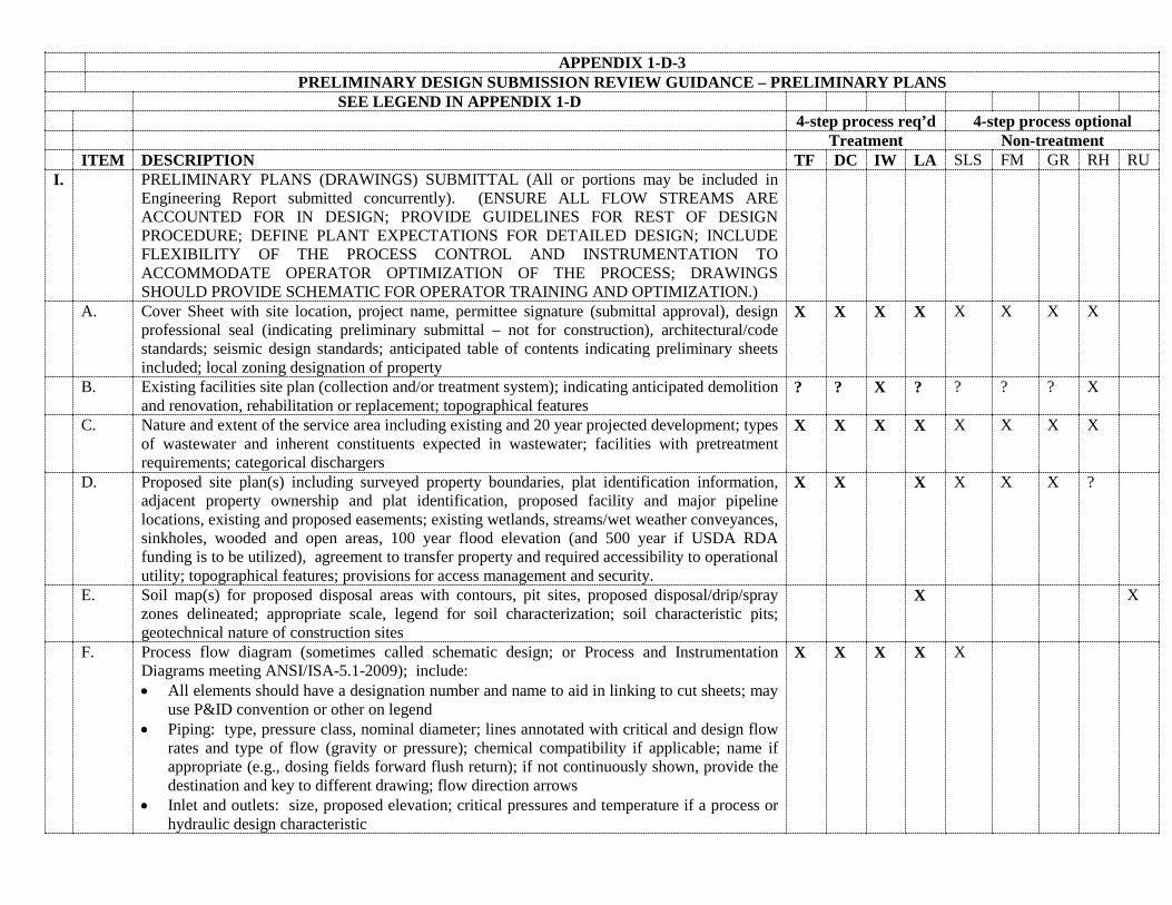
APPENDIX 1-D-3 PRELIMINARY DESIGN SUBMISSION REVIEW GUIDANCE – PRELIMINARY PLANS
SEE LEGEND IN APPENDIX 1-D 4-step process req’d 4-step process optional Treatment Non-treatment ITEM DESCRIPTION TF DC IW LA SLS FM GR RH RU I. PRELIMINARY PLANS (DRAWINGS) SUBMITTAL (All or portions may be included in
Engineering Report submitted concurrently). (ENSURE ALL FLOW STREAMS ARE ACCOUNTED FOR IN DESIGN; PROVIDE GUIDELINES FOR REST OF DESIGN PROCEDURE; DEFINE PLANT EXPECTATIONS FOR DETAILED DESIGN; INCLUDE FLEXIBILITY OF THE PROCESS CONTROL AND INSTRUMENTATION TO ACCOMMODATE OPERATOR OPTIMIZATION OF THE PROCESS; DRAWINGS SHOULD PROVIDE SCHEMATIC FOR OPERATOR TRAINING AND OPTIMIZATION.)
A. Cover Sheet with site location, project name, permittee signature (submittal approval), design professional seal (indicating preliminary submittal – not for construction), architectural/code standards; seismic design standards; anticipated table of contents indicating preliminary sheets included; local zoning designation of property
X X X X X X X X
B. Existing facilities site plan (collection and/or treatment system); indicating anticipated demolition and renovation, rehabilitation or replacement; topographical features
? ? X ? ? ? ? X
C. Nature and extent of the service area including existing and 20 year projected development; types of wastewater and inherent constituents expected in wastewater; facilities with pretreatment requirements; categorical dischargers
X X X X X X X X
D. Proposed site plan(s) including surveyed property boundaries, plat identification information, adjacent property ownership and plat identification, proposed facility and major pipeline locations, existing and proposed easements; existing wetlands, streams/wet weather conveyances, sinkholes, wooded and open areas, 100 year flood elevation (and 500 year if USDA RDA funding is to be utilized), agreement to transfer property and required accessibility to operational utility; topographical features; provisions for access management and security.
X X X X X X ?
E. Soil map(s) for proposed disposal areas with contours, pit sites, proposed disposal/drip/spray zones delineated; appropriate scale, legend for soil characterization; soil characteristic pits; geotechnical nature of construction sites
X X
F. Process flow diagram (sometimes called schematic design; or Process and Instrumentation Diagrams meeting ANSI/ISA-5.1-2009); include: • All elements should have a designation number and name to aid in linking to cut sheets; may
use P&ID convention or other on legend • Piping: type, pressure class, nominal diameter; lines annotated with critical and design flow
rates and type of flow (gravity or pressure); chemical compatibility if applicable; name if appropriate (e.g., dosing fields forward flush return); if not continuously shown, provide the destination and key to different drawing; flow direction arrows
• Inlet and outlets: size, proposed elevation; critical pressures and temperature if a process or hydraulic design characteristic
X X X X X
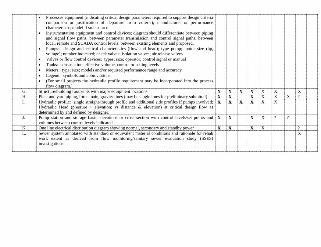
• Processes equipment (indicating critical design parameters required to support design criteria comparison or justification of departure from criteria); manufacturer or performance characteristic; model if sole source
• Instrumentation equipment and control devices; diagram should differentiate between piping and signal flow paths, between parameter transmission and control signal paths, between local, remote and SCADA control levels, between existing elements and proposed.
• Pumps: design and critical characteristics (flow and head); type pump; motor size (hp, voltage); number indicated; check valves; isolation valves; air release valves
• Valves or flow control devices: types; size; operator; control signal or manual • Tanks: construction, effective volume, control or setting levels • Meters: type; size; models and/or required performance range and accuracy • Legend: symbols and abbreviations • (For small projects the hydraulic profile requirement may be incorporated into the process
flow diagram.) G. Structure/building footprints with major equipment locations X X X X X X X H. Plant and yard piping, force main, gravity lines (may be single lines for preliminary submittal) X X X X X X ? I. Hydraulic profile: single straight-through profile and additional side profiles if pumps involved;
Hydraulic Head (pressure + elevation; vs distance & elevation) at critical design flow as determined by and defined by designer.
X X X X X X
J. Pump station and storage basin elevations or cross section with control levels/set points and volumes between control levels indicated
X X X X ? ?
K. One line electrical distribution diagram showing normal, secondary and standby power X X X X ? L. Sewer system annotated with standard or equivalent material conditions and rationale for rehab
work extent as derived from flow monitoring/sanitary sewer evaluation study (SSES) investigations.
X
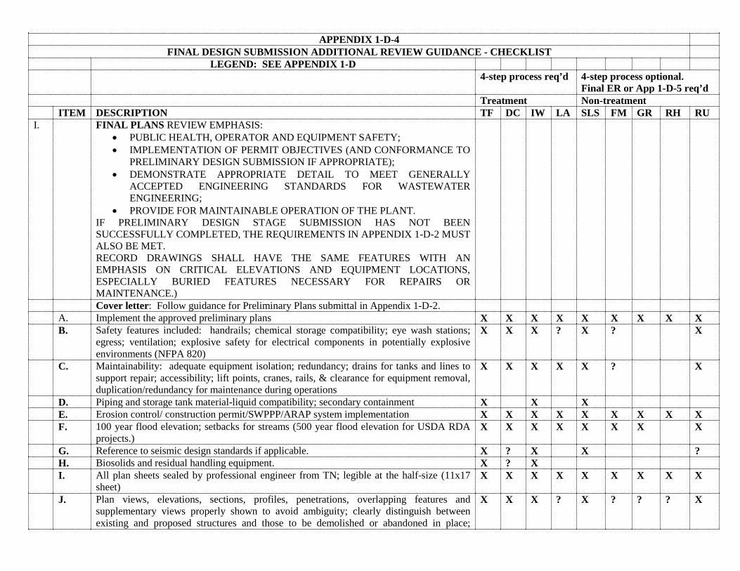
APPENDIX 1-D-4 FINAL DESIGN SUBMISSION ADDITIONAL REVIEW GUIDANCE - CHECKLIST
LEGEND: SEE APPENDIX 1-D 4-step process req’d 4-step process optional.
Final ER or App 1-D-5 req’d Treatment Non-treatment ITEM DESCRIPTION TF DC IW LA SLS FM GR RH RU I. FINAL PLANS REVIEW EMPHASIS:
• PUBLIC HEALTH, OPERATOR AND EQUIPMENT SAFETY; • IMPLEMENTATION OF PERMIT OBJECTIVES (AND CONFORMANCE TO
PRELIMINARY DESIGN SUBMISSION IF APPROPRIATE); • DEMONSTRATE APPROPRIATE DETAIL TO MEET GENERALLY
ACCEPTED ENGINEERING STANDARDS FOR WASTEWATER ENGINEERING;
• PROVIDE FOR MAINTAINABLE OPERATION OF THE PLANT. IF PRELIMINARY DESIGN STAGE SUBMISSION HAS NOT BEEN SUCCESSFULLY COMPLETED, THE REQUIREMENTS IN APPENDIX 1-D-2 MUST ALSO BE MET. RECORD DRAWINGS SHALL HAVE THE SAME FEATURES WITH AN EMPHASIS ON CRITICAL ELEVATIONS AND EQUIPMENT LOCATIONS, ESPECIALLY BURIED FEATURES NECESSARY FOR REPAIRS OR MAINTENANCE.)
Cover letter: Follow guidance for Preliminary Plans submittal in Appendix 1-D-2. A. Implement the approved preliminary plans X X X X X X X X X B. Safety features included: handrails; chemical storage compatibility; eye wash stations;
egress; ventilation; explosive safety for electrical components in potentially explosive environments (NFPA 820)
X X X ? X ? X
C. Maintainability: adequate equipment isolation; redundancy; drains for tanks and lines to support repair; accessibility; lift points, cranes, rails, & clearance for equipment removal, duplication/redundancy for maintenance during operations
X X X X X ? X
D. Piping and storage tank material-liquid compatibility; secondary containment X X X E. Erosion control/ construction permit/SWPPP/ARAP system implementation X X X X X X X X X F. 100 year flood elevation; setbacks for streams (500 year flood elevation for USDA RDA
projects.) X X X X X X X X
G. Reference to seismic design standards if applicable. X ? X X ? H. Biosolids and residual handling equipment. X ? X I. All plan sheets sealed by professional engineer from TN; legible at the half-size (11x17
sheet) X X X X X X X X X
J. Plan views, elevations, sections, profiles, penetrations, overlapping features and supplementary views properly shown to avoid ambiguity; clearly distinguish between existing and proposed structures and those to be demolished or abandoned in place;
X X X ? X ? ? ? X
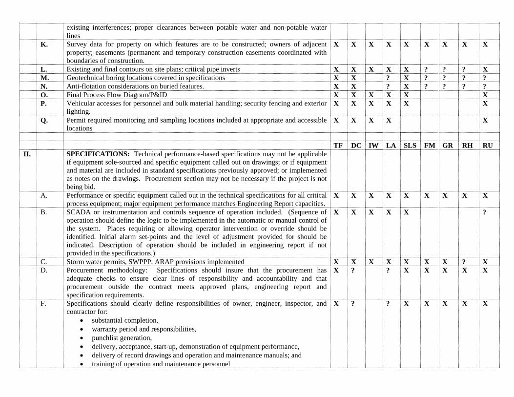
existing interferences; proper clearances between potable water and non-potable water lines
K. Survey data for property on which features are to be constructed; owners of adjacent property; easements (permanent and temporary construction easements coordinated with boundaries of construction.
X X X X X X X X X
L. Existing and final contours on site plans; critical pipe inverts X X X X X ? ? ? X M. Geotechnical boring locations covered in specifications X X ? X ? ? ? ? N. Anti-flotation considerations on buried features. X X ? X ? ? ? ? O. Final Process Flow Diagram/P&ID X X X X X X P. Vehicular accesses for personnel and bulk material handling; security fencing and exterior
lighting. X X X X X X
Q. Permit required monitoring and sampling locations included at appropriate and accessible locations
X X X X X
TF DC IW LA SLS FM GR RH RU II. SPECIFICATIONS: Technical performance-based specifications may not be applicable
if equipment sole-sourced and specific equipment called out on drawings; or if equipment and material are included in standard specifications previously approved; or implemented as notes on the drawings. Procurement section may not be necessary if the project is not being bid.
A. Performance or specific equipment called out in the technical specifications for all critical process equipment; major equipment performance matches Engineering Report capacities.
X X X X X X X X X
B. SCADA or instrumentation and controls sequence of operation included. (Sequence of operation should define the logic to be implemented in the automatic or manual control of the system. Places requiring or allowing operator intervention or override should be identified. Initial alarm set-points and the level of adjustment provided for should be indicated. Description of operation should be included in engineering report if not provided in the specifications.)
X X X X X ?
C. Storm water permits, SWPPP, ARAP provisions implemented X X X X X X X ? X D. Procurement methodology: Specifications should insure that the procurement has
adequate checks to ensure clear lines of responsibility and accountability and that procurement outside the contract meets approved plans, engineering report and specification requirements.
X ? ? X X X X X
F. Specifications should clearly define responsibilities of owner, engineer, inspector, and contractor for:
• substantial completion, • warranty period and responsibilities, • punchlist generation, • delivery, acceptance, start-up, demonstration of equipment performance, • delivery of record drawings and operation and maintenance manuals; and • training of operation and maintenance personnel
X ? ? X X X X X
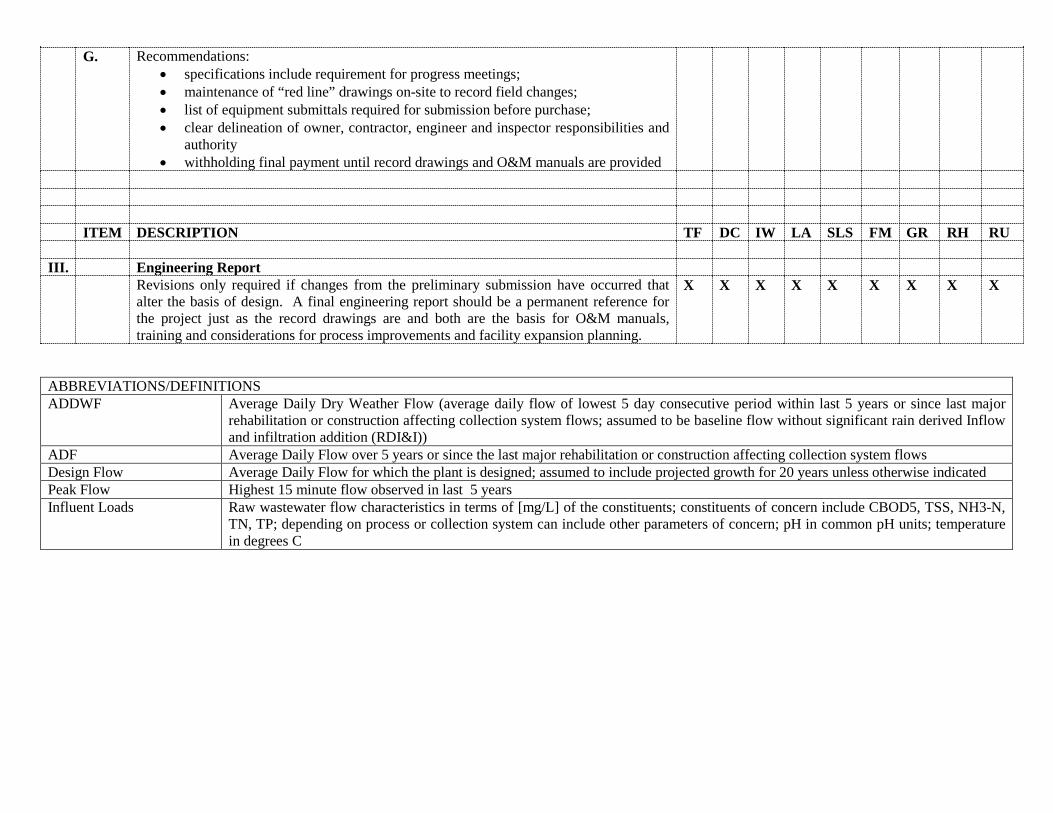
G. Recommendations: • specifications include requirement for progress meetings; • maintenance of “red line” drawings on-site to record field changes; • list of equipment submittals required for submission before purchase; • clear delineation of owner, contractor, engineer and inspector responsibilities and
authority • withholding final payment until record drawings and O&M manuals are provided
ITEM DESCRIPTION TF DC IW LA SLS FM GR RH RU III. Engineering Report Revisions only required if changes from the preliminary submission have occurred that
alter the basis of design. A final engineering report should be a permanent reference for the project just as the record drawings are and both are the basis for O&M manuals, training and considerations for process improvements and facility expansion planning.
X X X X X X X X X
ABBREVIATIONS/DEFINITIONS ADDWF Average Daily Dry Weather Flow (average daily flow of lowest 5 day consecutive period within last 5 years or since last major
rehabilitation or construction affecting collection system flows; assumed to be baseline flow without significant rain derived Inflow and infiltration addition (RDI&I))
ADF Average Daily Flow over 5 years or since the last major rehabilitation or construction affecting collection system flows Design Flow Average Daily Flow for which the plant is designed; assumed to include projected growth for 20 years unless otherwise indicated Peak Flow Highest 15 minute flow observed in last 5 years Influent Loads Raw wastewater flow characteristics in terms of [mg/L] of the constituents; constituents of concern include CBOD5, TSS, NH3-N,
TN, TP; depending on process or collection system can include other parameters of concern; pH in common pH units; temperature in degrees C

THIS PAGE INTENTIONALLY LEFT BLANK
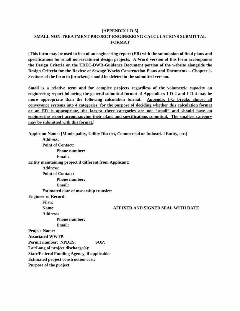
[APPENDIX I-D-5] SMALL NON-TREATMENT PROJECT ENGINEERING CALCULATIONS SUBMITTAL
FORMAT
[This form may be used in lieu of an engineering report (ER) with the submission of final plans and specifications for small non-treatment design projects. A Word version of this form accompanies the Design Criteria on the TDEC-DWR-Guidance Document portion of the website alongside the Design Criteria for the Review of Sewage Works Construction Plans and Documents – Chapter 1. Sections of the form in [brackets] should be deleted in the submitted version. Small is a relative term and for complex projects regardless of the volumetric capacity an engineering report following the general submittal format of Appendices 1-D-2 and 1-D-4 may be more appropriate than the following calculation format. Appendix 1-G breaks almost all conveyance systems into 4 categories; for the purpose of deciding whether this calculation format or an ER is appropriate, the largest three categories are not “small” and should have an engineering report accompanying their plans and specifications submittal. The smallest category may be submitted with this format.] Applicant Name: [Municipality, Utility District, Commercial or Industrial Entity, etc.] Address: Point of Contact: Phone number: Email: Entity maintaining project if different from Applicant: Address: Point of Contact: Phone number: Email: Estimated date of ownership transfer: Engineer of Record:
Firm: Name: AFFIXED AND SIGNED SEAL WITH DATE Address: Phone number: Email: Project Name: Associated WWTP: Permit number: NPDES: SOP: Lat/Long of project discharge(s): State/Federal Funding Agency, if applicable: Estimated project construction cost: Purpose of the project:
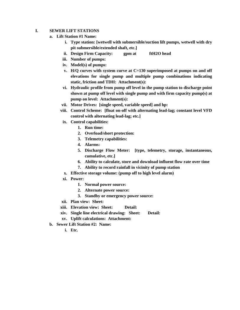
I. SEWER LIFT STATIONS a. Lift Station #1 Name:
i. Type station: [wetwell with submersible/suction lift pumps, wetwell with dry pit submersible/extended shaft, etc.]
ii. Design Firm Capacity: gpm at ftH2O head iii. Number of pumps: iv. Model(s) of pumps: v. H/Q curves with system curve at C=130 superimposed at pumps on and off
elevations for single pump and multiple pump combinations indicating static, friction and TDH: Attachment(s):
vi. Hydraulic profile from pump off level in the pump station to discharge point shown at pump off level with single pump and with firm capacity pump(s) at pump on level: Attachment(s):
vii. Motor Drives: [single speed, variable speed] and hp: viii. Control Scheme: [float on-off with alternating lead-lag; constant level VFD
control with alternating lead-lag; etc.] ix. Control capabilities:
1. Run time: 2. Overload/short protection: 3. Telemetry capabilities: 4. Alarms: 5. Discharge Flow Meter: [type, telemetry, storage, instantaneous,
cumulative, etc.] 6. Ability to calculate, store and download influent flow rate over time 7. Ability to record rainfall in vicinity of pump station
x. Effective storage volume: (pump off to high level alarm) xi. Power:
1. Normal power source: 2. Alternate power source: 3. Standby or emergency power source:
xii. Plan view: Sheet: xiii. Elevation view: Sheet: Detail: xiv. Single line electrical drawing: Sheet: Detail: xv. Uplift calculations: Attachment:
b. Sewer Lift Station #2: Name: i. Etc.
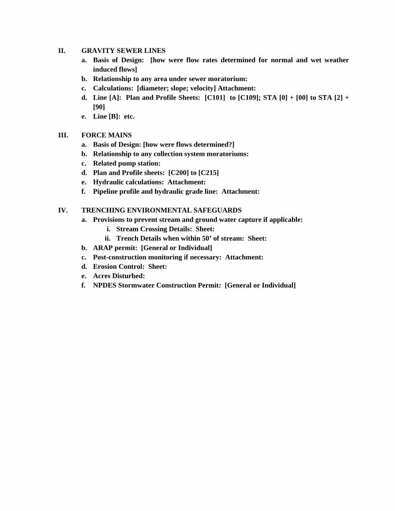
II. GRAVITY SEWER LINES a. Basis of Design: [how were flow rates determined for normal and wet weather
induced flows] b. Relationship to any area under sewer moratorium: c. Calculations: [diameter; slope; velocity] Attachment: d. Line [A]: Plan and Profile Sheets: [C101] to [C109]; STA [0] + [00] to STA [2] +
[90] e. Line [B]: etc.
III. FORCE MAINS
a. Basis of Design: [how were flows determined?] b. Relationship to any collection system moratoriums: c. Related pump station: d. Plan and Profile sheets: [C200] to [C215] e. Hydraulic calculations: Attachment: f. Pipeline profile and hydraulic grade line: Attachment:
IV. TRENCHING ENVIRONMENTAL SAFEGUARDS
a. Provisions to prevent stream and ground water capture if applicable: i. Stream Crossing Details: Sheet:
ii. Trench Details when within 50’ of stream: Sheet: b. ARAP permit: [General or Individual] c. Post-construction monitoring if necessary: Attachment: d. Erosion Control: Sheet: e. Acres Disturbed: f. NPDES Stormwater Construction Permit: [General or Individual]

THIS PAGE INTENTIONALLY LEFT BLANK

DWR-NPDES/SOP-G-01-WW Design Criteria Chapter 1-110117 Design Criteria for Review of Sewage Works Construction Plans and Documents
Chapter 1
November 1, 2017
APPENDIX 1-E
Preliminary Engineering Report (PER) Guidance
Preliminary Engineering Reports (PERs) are often reviewed by the Division in conjunction with funding agencies such as State Revolving Fund (SRF), US Department of Agriculture-Rural Development Agency (USDA-RDA), and Community Block Development Grants (CDBGs). In addition a Corrective Action Plan/Engineering Report is more often a CAP/PER than a CAP/ER. A PER format has been developed jointly by a number of federal funding agencies and is attached as Appendix 1-E-1 for use by engineering firms submitting a PER when such is required by the Division prior to or as part of the project Site Approval or Preliminary Engineering submission phases.
Appendix 1-E-2 represents additional requirements for the SRF Loan Program’s Facilities Planning Document that is normally going to be provided to SRF at the same time in the engineering design effort as a PER. Submitting firms should follow the outline for the Facilities Planning Document and make sure that the technical portion covers the material for both documents.
If the format attached is to be used for Division submission and a new or expanded wastewater treatment facility is included, the life cycle cost analyses (LCCA) should include evaluation of sewer rehab for I&I reduction and plant operational optimization. Likewise, the individual federal funding agencies may have addenda or modifications to meet their specific funding requirements not included in the version of the PER format included here. However, this format is generally considered the minimum acceptable.

DWR-NPDES/SOP-G-01-WW Design Criteria Chapter 1-110117 Design Criteria for Review of Sewage Works Construction Plans and Documents
Chapter 1
November 1, 2017
APPENDIX 1-E-1
JOINT FEDERAL INTERAGENCY MEMORANDUM –Preliminary Engineering Report Outlines
• USDA-RD-RUS Water and Environmental Programs • USEPA, Office of Water, Office of Ground Water and Drinking Water and Office of
Wastewater Management • US Department of Housing and Urban Development (HUD), Office of Community Planning
and Development • US Department of Health and Human Services, Indian Health Service (IHS) • Small Communities Water Infrastructure Exchange
THIS APPENDIX IS INCLUDED AS AN ENGINEERING PLANNING AID FOR PERs SUBMITTED AS PART OF THE TDEC-DWR PLANS REVIEW PROCESS. WHEN FEDERAL FUNDING AGENCIES WILL RECEIVE SUBMISSIONS, THE APPLICANT SHOULD CHECK TO ENSURE THE LATEST AGENCY’S INSTRUCTIONS ARE COMPLIED WITH.

DWR-NPDES/SOP-G-01-WW Design Criteria Chapter 1-110117 Design Criteria for Review of Sewage Works Construction Plans and Documents
Chapter 1
November 1, 2017
THIS PAGE INTENTIONALLY LEFT BLANK
January 16, 2013
INTERAGENCY MEMORANDUM
Attached is a document explaining recommended best practice for the development of Preliminary Engineering Reports in support of funding applications for development of drinking water, wastewater, stormwater, and solid waste systems.
The best practice document was developed cooperatively by: US Department of Agriculture, Rural Development, Rural Utilities Service, Water and
Environmental Programs; US Environmental Protection Agency (EPA), Office of Water, Office of Ground Water
and Drinking Water and Office of Wastewater Management; US Department of Housing and Urban Development (HUD), Office of Community
Planning and Development; US Department of Health and Human Services, Indian Health Service (IHS); Small Communities Water Infrastructure Exchange;
Extensive input from participating state administering agencies was also very important to the development of this document.
Federal agencies that cooperatively developed this document strongly encourage its use by funding agencies as part of the application process or project development. State administered programs are encouraged to adopt this document but are not required to do so, as it is up to a state administering agency’s discretion to adopt it, based on the needs of the state administering agency.
A Preliminary Engineering Report (Report) is a planning document required by many state and federal funding agencies as part of the process of obtaining financial assistance for development of drinking water, wastewater, solid waste, and stormwater facilities. The attached Report outline details the requirements that funding agencies have adopted when a Report is required.
In general the Report should include a description of existing facilities and a description of the issues being addressed by the proposed project. It should identify alternatives, present a life cycle cost analysis of technically feasible alternatives and propose a specific course of action. The Report should also include a detailed current cost estimate of the recommended alternative. The attached outline describes these and other sections to be included in the Report.
Projects utilizing direct federal funding also require an environmental review in accordance with the National Environmental Policy Act (NEPA). The Report should indicate that environmental issues were considered as part of the engineering planning and include environmental information pertinent to engineering planning.
For state administered funding programs, a determination of whether the outline applies to a given program or project is made by the state administering agency. When a program or agency adopts this outline, it may adopt a portion or the entire outline as applicable to the program or project in question at the discretion of the agency. Some state and federal funding agencies will not require the Report for every project or may waive portions of the Report that do not apply to their application process, however a Report thoroughly addressing all of the contents of this outline will meet the requirements of most agencies that have adopted this outline.
The detailed outline provides information on what to include in a Report. The level of detail required may also vary according to the complexity of the specific project. Reports should conform substantially to this detailed outline and otherwise be prepared and presented in a professional manner. Many funding agencies require that the document be developed by a Professional Engineer registered in the state or other jurisdiction where the project is to be constructed unless exempt from this requirement. Please check with applicable funding agencies to determine if the agencies require supplementary information beyond the scope of this outline.
Any preliminary design information must be written in accordance with the regulatory requirements of the state or territory where the project will be built.
Information provided in the Report may be used to process requests for funding. Completeness and accuracy are therefore essential for timely processing of an application. Please contact the appropriate state or federal funding agencies with any questions about development of the Report and applications for funding as early in the process as practicable.
Questions about this document should be referred to the applicable state administering agency, regional office of the applicable federal agency, or to the following federal contacts:
Agency Contact Email Address Phone USDA/RUS Benjamin Shuman, PE [email protected] 202‐720‐1784 EPA/DWSRF Kirsten Anderer, PE [email protected] 202‐564‐3134 EPA/CWSRF Matt King [email protected] 202‐564‐2871 HUD Stephen Rhodeside [email protected] 202‐708‐1322 IHS Dana Baer, PE [email protected] 301‐443‐1345
2
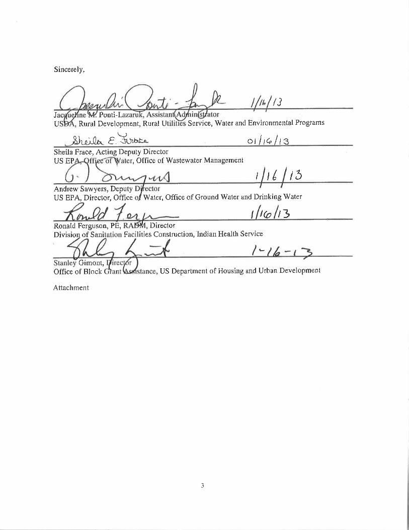
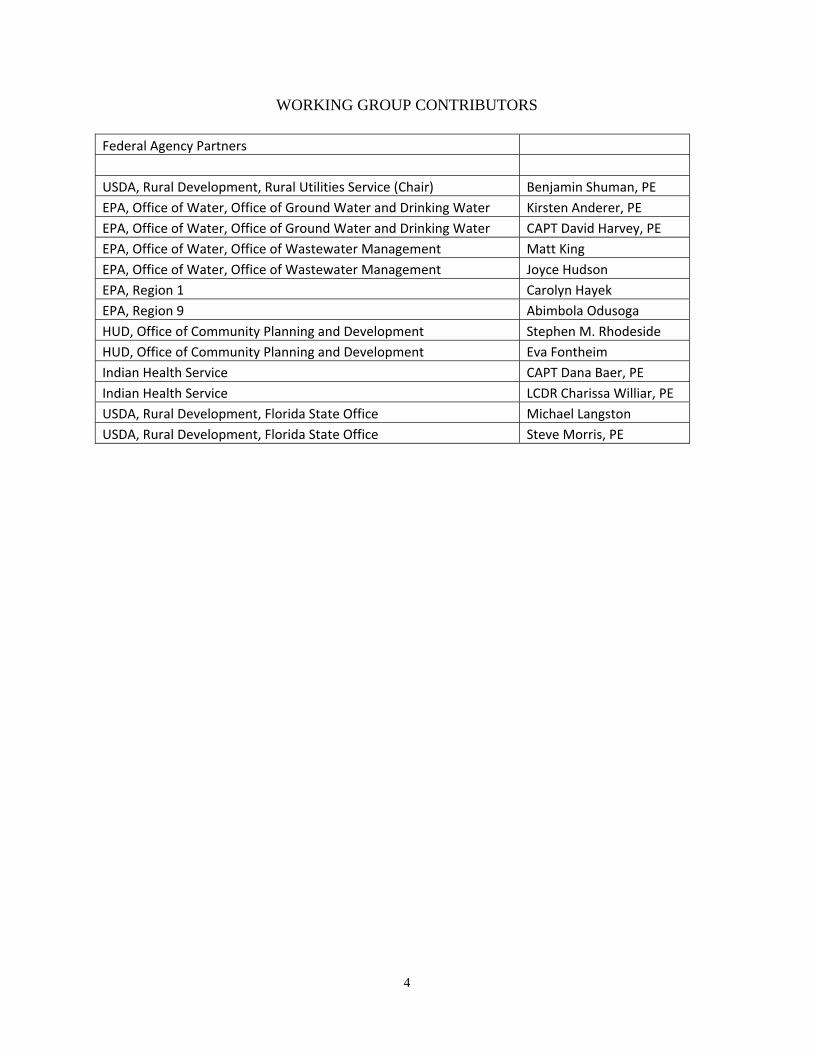
WORKING GROUP CONTRIBUTORS
Federal Agency Partners
USDA, Rural Development, Rural Utilities Service (Chair) Benjamin Shuman, PE
EPA, Office of Water, Office of Ground Water and Drinking Water Kirsten Anderer, PE
EPA, Office of Water, Office of Ground Water and Drinking Water CAPT David Harvey, PE
EPA, Office of Water, Office of Wastewater Management Matt King
EPA, Office of Water, Office of Wastewater Management Joyce Hudson
EPA, Region 1 Carolyn Hayek
EPA, Region 9 Abimbola Odusoga
HUD, Office of Community Planning and Development Stephen M. Rhodeside
HUD, Office of Community Planning and Development Eva Fontheim
Indian Health Service CAPT Dana Baer, PE
Indian Health Service LCDR Charissa Williar, PE
USDA, Rural Development, Florida State Office Michael Langston
USDA, Rural Development, Florida State Office Steve Morris, PE
4
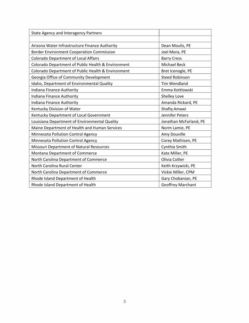
State Agency and Interagency Partners
Arizona Water Infrastructure Finance Authority Dean Moulis, PE
Border Environment Cooperation Commission Joel Mora, PE
Colorado Department of Local Affairs Barry Cress
Colorado Department of Public Health & Environment Michael Beck
Colorado Department of Public Health & Environment Bret Icenogle, PE
Georgia Office of Community Development Steed Robinson
Idaho, Department of Environmental Quality Tim Wendland
Indiana Finance Authority Emma Kottlowski
Indiana Finance Authority Shelley Love
Indiana Finance Authority Amanda Rickard, PE
Kentucky Division of Water Shafiq Amawi
Kentucky Department of Local Government Jennifer Peters
Louisiana Department of Environmental Quality Jonathan McFarland, PE
Maine Department of Health and Human Services Norm Lamie, PE
Minnesota Pollution Control Agency Amy Douville
Minnesota Pollution Control Agency Corey Mathisen, PE
Missouri Department of Natural Resources Cynthia Smith
Montana Department of Commerce Kate Miller, PE
North Carolina Department of Commerce Olivia Collier
North Carolina Rural Center Keith Krzywicki, PE
North Carolina Department of Commerce Vickie Miller, CPM
Rhode Island Department of Health Gary Chobanian, PE
Rhode Island Department of Health Geoffrey Marchant
5

ABBREVIATIONS
NEPA – National Environmental Policy Act NPV – Net Present Value O&M – Operations and Maintenance OMB – Office of Management and Budget Report – Preliminary Engineering Report SPPW – Single Payment Present Worth USPW – Uniform Series Present Worth
6
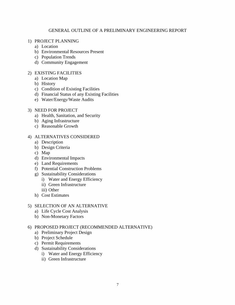
GENERAL OUTLINE OF A PRELIMINARY ENGINEERING REPORT
1) PROJECT PLANNING a) Location b) Environmental Resources Present c) Population Trends d) Community Engagement
2) EXISTING FACILITIES a) Location Map b) History c) Condition of Existing Facilities d) Financial Status of any Existing Facilities e) Water/Energy/Waste Audits
3) NEED FOR PROJECT a) Health, Sanitation, and Security b) Aging Infrastructure c) Reasonable Growth
4) ALTERNATIVES CONSIDERED a) Description b) Design Criteria c) Map d) Environmental Impacts e) Land Requirements f) Potential Construction Problems g) Sustainability Considerations
i) Water and Energy Efficiency ii) Green Infrastructure iii) Other
h) Cost Estimates
5) SELECTION OF AN ALTERNATIVE a) Life Cycle Cost Analysis b) Non-Monetary Factors
6) PROPOSED PROJECT (RECOMMENDED ALTERNATIVE) a) Preliminary Project Design b) Project Schedule c) Permit Requirements d) Sustainability Considerations
i) Water and Energy Efficiency ii) Green Infrastructure
7
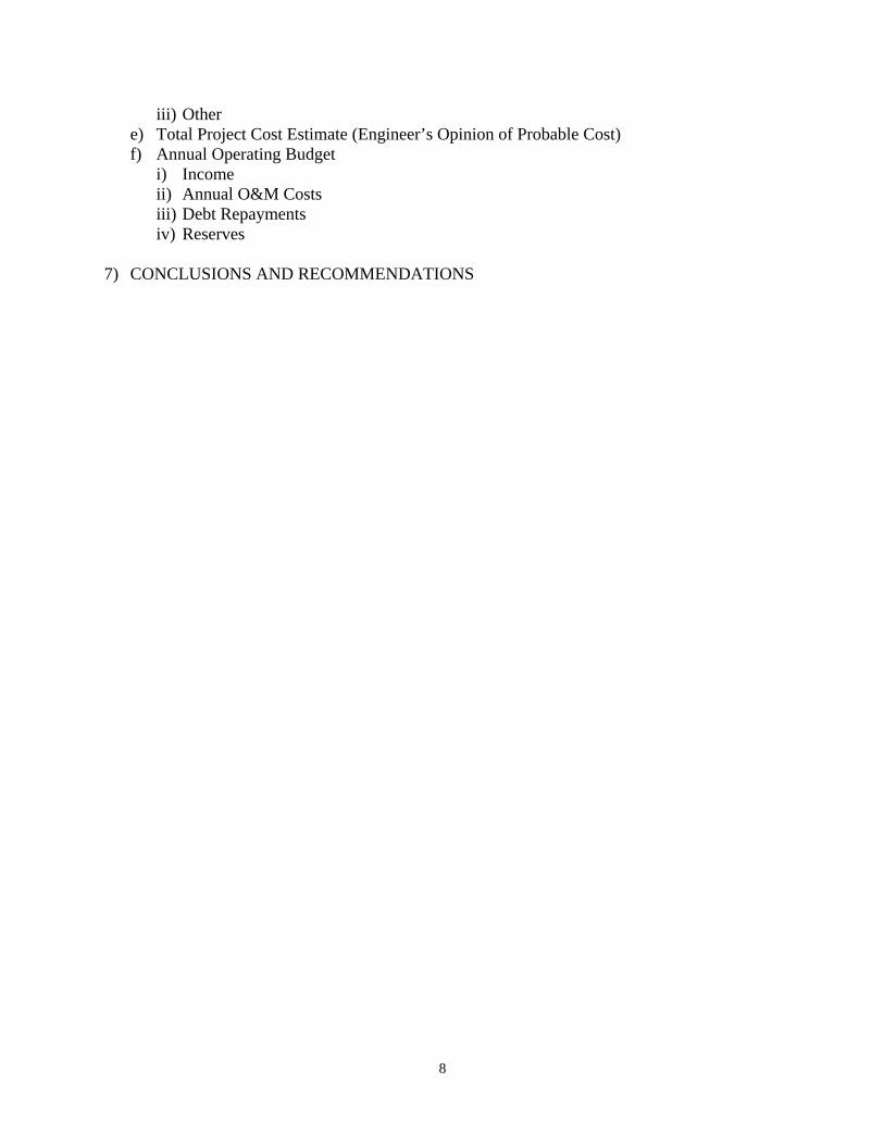
iii) Other e) Total Project Cost Estimate (Engineer’s Opinion of Probable Cost) f) Annual Operating Budget
i) Income ii) Annual O&M Costs iii) Debt Repayments iv) Reserves
7) CONCLUSIONS AND RECOMMENDATIONS
8

DETAILED OUTLINE OF A PRELIMINARY ENGINEERING REPORT
1) PROJECT PLANNING
Describe the area under consideration. Service may be provided by a combination of central, cluster, and/or centrally managed individual facilities. The description should include information on the following:
a) Location. Provide scale maps and photographs of the project planning area and any existing service areas. Include legal and natural boundaries and a topographical map of the service area.
b) Environmental Resources Present. Provide maps, photographs, and/or a narrative description of environmental resources present in the project planning area that affect design of the project. Environmental review information that has already been developed to meet requirements of NEPA or a state equivalent review process can be used here.
c) Population Trends. Provide U.S. Census or other population data (including references) for the service area for at least the past two decades if available. Population projections for the project planning area and concentrated growth areas should be provided for the project design period. Base projections on historical records with justification from recognized sources.
d) Community Engagement. Describe the utility’s approach used (or proposed for use) to engage the community in the project planning process. The projectplanning process should help the community develop an understanding of the need for the project, the utility operational service levels required, funding and revenue strategies to meet these requirements, along with other considerations.
2) EXISTING FACILITIES
Describe each part (e.g. processing unit) of the existing facility and include the following information:
a) Location Map. Provide a map and a schematic process layout of all existing facilities. Identify facilities that are no longer in use or abandoned. Include photographs of existing facilities.
b) History. Indicate when major system components were constructed, renovated, expanded, or removed from service. Discuss any component failures and the cause for the failure. Provide a history of any applicable violations of regulatory requirements.
c) Condition of Existing Facilities. Describe present condition; suitability for continued use; adequacy of current facilities; and their conveyance, treatment, storage, and disposal capabilities. Describe the existing capacity of each component. Describe and reference compliance with applicable federal, state, and local laws. Include a brief analysis of overall current energy consumption. Reference an asset management plan if applicable.
9
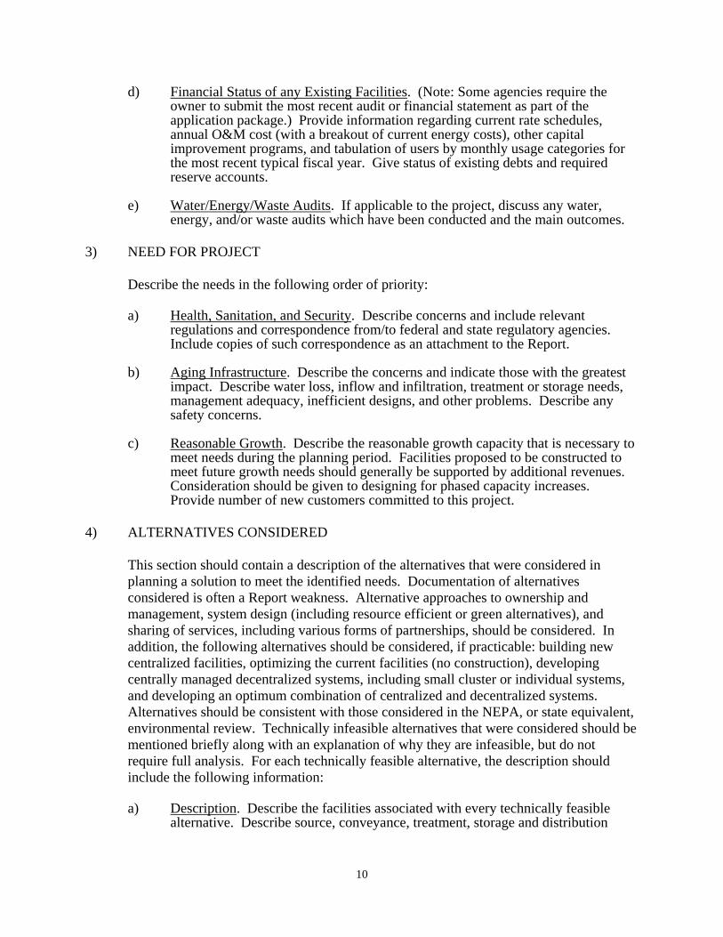
d) Financial Status of any Existing Facilities. (Note: Some agencies require the owner to submit the most recent audit or financial statement as part of the application package.) Provide information regarding current rate schedules, annual O&M cost (with a breakout of current energy costs), other capital improvement programs, and tabulation of users by monthly usage categories for the most recent typical fiscal year. Give status of existing debts and required reserve accounts.
e) Water/Energy/Waste Audits. If applicable to the project, discuss any water, energy, and/or waste audits which have been conducted and the main outcomes.
3) NEED FOR PROJECT
Describe the needs in the following order of priority:
a) Health, Sanitation, and Security. Describe concerns and include relevant regulations and correspondence from/to federal and state regulatory agencies. Include copies of such correspondence as an attachment to the Report.
b) Aging Infrastructure. Describe the concerns and indicate those with the greatest impact. Describe water loss, inflow and infiltration, treatment or storage needs, management adequacy, inefficient designs, and other problems. Describe anysafety concerns.
c) Reasonable Growth. Describe the reasonable growth capacity that is necessary to meet needs during the planning period. Facilities proposed to be constructed to meet future growth needs should generally be supported by additional revenues. Consideration should be given to designing for phased capacity increases. Provide number of new customers committed to this project.
4) ALTERNATIVES CONSIDERED
This section should contain a description of the alternatives that were considered in planning a solution to meet the identified needs. Documentation of alternatives considered is often a Report weakness. Alternative approaches to ownership and management, system design (including resource efficient or green alternatives), and sharing of services, including various forms of partnerships, should be considered. In addition, the following alternatives should be considered, if practicable: building new centralized facilities, optimizing the current facilities (no construction), developing centrally managed decentralized systems, including small cluster or individual systems, and developing an optimum combination of centralized and decentralized systems. Alternatives should be consistent with those considered in the NEPA, or state equivalent, environmental review. Technically infeasible alternatives that were considered should be mentioned briefly along with an explanation of why they are infeasible, but do not require full analysis. For each technically feasible alternative, the description should include the following information:
a) Description. Describe the facilities associated with every technically feasible alternative. Describe source, conveyance, treatment, storage and distribution
10

facilities for each alternative. A feasible system may include a combination of centralized and decentralized (on-site or cluster) facilities.
b) Design Criteria. State the design parameters used for evaluation purposes. These parameters should comply with federal, state, and agency design policies and regulatory requirements.
c) Map. Provide a schematic layout map to scale and a process diagram if applicable. If applicable, include future expansion of the facility.
d) Environmental Impacts. Provide information about how the specific alternative may impact the environment. Describe only those unique direct and indirect impacts on floodplains, wetlands, other important land resources, endangered species, historical and archaeological properties, etc., as they relate to each specific alternative evaluated. Include generation and management of residuals and wastes.
e) Land Requirements. Identify sites and easements required. Further specifywhether these properties are currently owned, to be acquired, leased, or have access agreements.
f) Potential Construction Problems. Discuss concerns such as subsurface rock, high water table, limited access, existing resource or site impairment, or other conditions which may affect cost of construction or operation of facility.
g) Sustainability Considerations. Sustainable utility management practices include environmental, social, and economic benefits that aid in creating a resilient utility.
i) Water and Energy Efficiency. Discuss water reuse, water efficiency, water conservation, energy efficient design (i.e. reduction in electrical demand), and/or renewable generation of energy, and/or minimization of carbon footprint, if applicable to the alternative. Alternatively, discuss the water and energy usage for this option as compared to other alternatives.
ii) Green Infrastructure. Discuss aspects of project that preserve or mimic natural processes to manage stormwater, if applicable to the alternative. Address management of runoff volume and peak flows through infiltration, evapotranspiration, and/or harvest and use, if applicable.
iii) Other. Discuss any other aspects of sustainability (such as resiliency or operational simplicity) that are incorporated into the alternative, if applicable.
h) Cost Estimates. Provide cost estimates for each alternative, including a breakdown of the following costs associated with the project: construction, non-construction, and annual O&M costs. A construction contingency should beincluded as a non-construction cost. Cost estimates should be included with the descriptions of each technically feasible alternative. O&M costs should include a rough breakdown by O&M category (see example below) and not just a value for each alternative. Information from other sources, such as the recipient’s accountant or other known technical service providers, can be incorporated to assist in the development of this section. The cost derived will be used in the life cycle cost analysis described in Section 5 a.
11
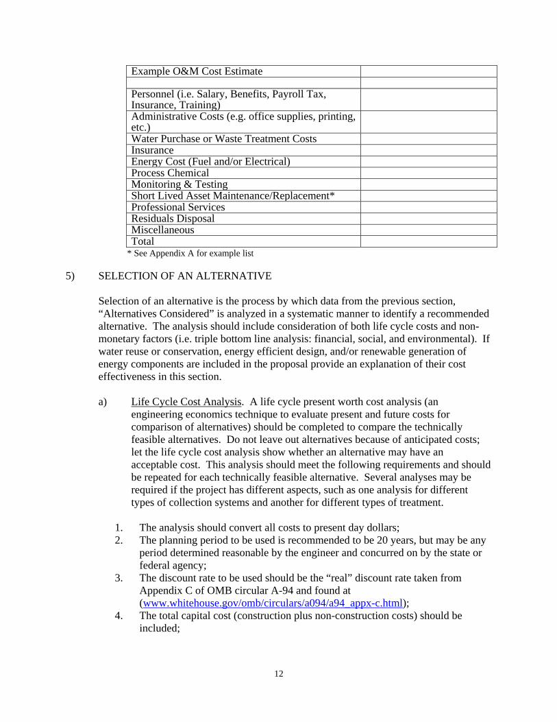
Example O&M Cost Estimate
Personnel (i.e. Salary, Benefits, Payroll Tax,Insurance, Training) Administrative Costs (e.g. office supplies, printing, etc.) Water Purchase or Waste Treatment Costs Insurance Energy Cost (Fuel and/or Electrical) Process Chemical Monitoring & Testing Short Lived Asset Maintenance/Replacement* Professional Services Residuals Disposal Miscellaneous Total
* See Appendix A for example list
5) SELECTION OF AN ALTERNATIVE
Selection of an alternative is the process by which data from the previous section, “Alternatives Considered” is analyzed in a systematic manner to identify a recommended alternative. The analysis should include consideration of both life cycle costs and non-monetary factors (i.e. triple bottom line analysis: financial, social, and environmental). If water reuse or conservation, energy efficient design, and/or renewable generation of energy components are included in the proposal provide an explanation of their cost effectiveness in this section.
a) Life Cycle Cost Analysis. A life cycle present worth cost analysis (an engineering economics technique to evaluate present and future costs for comparison of alternatives) should be completed to compare the technically feasible alternatives. Do not leave out alternatives because of anticipated costs; let the life cycle cost analysis show whether an alternative may have an acceptable cost. This analysis should meet the following requirements and should be repeated for each technically feasible alternative. Several analyses may be required if the project has different aspects, such as one analysis for different types of collection systems and another for different types of treatment.
1. The analysis should convert all costs to present day dollars; 2. The planning period to be used is recommended to be 20 years, but may be any
period determined reasonable by the engineer and concurred on by the state or federal agency;
3. The discount rate to be used should be the “real” discount rate taken from Appendix C of OMB circular A-94 and found at (www.whitehouse.gov/omb/circulars/a094/a94_appx-c.html);
4. The total capital cost (construction plus non-construction costs) should be included;
12

5. Annual O&M costs should be converted to present day dollars using a uniform series present worth (USPW) calculation;
6. The salvage value of the constructed project should be estimated using the anticipated life expectancy of the constructed items using straight line depreciation calculated at the end of the planning period and converted to present day dollars;
7. The present worth of the salvage value should be subtracted from the present worth costs;
8. The net present value (NPV) is then calculated for each technically feasible alternative as the sum of the capital cost (C) plus the present worth of the uniform series of annual O&M (USPW (O&M)) costs minus the single payment present worth of the salvage value (SPPW(S)):
NPV = C + USPW (O&M) – SPPW (S)
9. A table showing the capital cost, annual O&M cost, salvage value, present worth of each of these values, and the NPV should be developed for state or federal agency review. All factors (major and minor components), discount rates, and planning periods used should be shown within the table;
10. Short lived asset costs (See Appendix A for examples) should also be included in the life cycle cost analysis if determined appropriate by the consulting engineer or agency. Life cycles of short lived assets should be tailored to the facilities being constructed and be based on generally accepted design life. Different features in the system may have varied life cycles.
b) Non-Monetary Factors. Non-monetary factors, including social and environmental aspects (e.g. sustainability considerations, operator training requirements, permit issues, community objections, reduction of greenhouse gas emissions, wetland relocation) should also be considered in determining which alternative is recommended and may be factored into the calculations.
6) PROPOSED PROJECT (RECOMMENDED ALTERNATIVE)
The engineer should include a recommendation for which alternative(s) should be implemented. This section should contain a fully developed description of the proposed project based on the preliminary description under the evaluation of alternatives. Include a schematic for any treatment processes, a layout of the system, and a location map of the proposed facilities. At least the following information should be included as applicable to the specific project:
a) Preliminary Project Design.
i) Drinking Water:
Water Supply. Include requirements for quality and quantity. Describe recommended source, including site and allocation allowed.
13
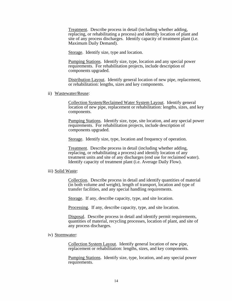
Treatment. Describe process in detail (including whether adding, replacing, or rehabilitating a process) and identify location of plant and site of any process discharges. Identify capacity of treatment plant (i.e. Maximum Daily Demand).
Storage. Identify size, type and location.
Pumping Stations. Identify size, type, location and any special power requirements. For rehabilitation projects, include description of components upgraded.
Distribution Layout. Identify general location of new pipe, replacement, or rehabilitation: lengths, sizes and key components.
ii) Wastewater/Reuse:
Collection System/Reclaimed Water System Layout. Identify generallocation of new pipe, replacement or rehabilitation: lengths, sizes, and key components.
Pumping Stations. Identify size, type, site location, and any special power requirements. For rehabilitation projects, include description of components upgraded.
Storage. Identify size, type, location and frequency of operation.
Treatment. Describe process in detail (including whether adding, replacing, or rehabilitating a process) and identify location of any treatment units and site of any discharges (end use for reclaimed water). Identify capacity of treatment plant (i.e. Average Daily Flow).
iii) Solid Waste:
Collection. Describe process in detail and identify quantities of material (in both volume and weight), length of transport, location and type of transfer facilities, and any special handling requirements.
Storage. If any, describe capacity, type, and site location.
Processing. If any, describe capacity, type, and site location.
Disposal. Describe process in detail and identify permit requirements, quantities of material, recycling processes, location of plant, and site of any process discharges.
iv) Stormwater:
Collection System Layout. Identify general location of new pipe, replacement or rehabilitation: lengths, sizes, and key components.
Pumping Stations. Identify size, type, location, and any special power requirements.
14

Treatment. Describe treatment process in detail. Identify location oftreatment facilities and process discharges. Capacity of treatment process should also be addressed.
Storage. Identify size, type, location and frequency of operation.
Disposal. Describe type of disposal facilities and location.
Green Infrastructure. Provide the following information for green infrastructure alternatives:
Control Measures Selected. Identify types of control measures selected (e.g., vegetated areas, planter boxes, permeable pavement, rainwater cisterns).
Layout: Identify placement of green infrastructure control measures, flow paths, and drainage area for each control measure.
Sizing: Identify surface area and water storage volume for each green infrastructure control measure. Where applicable, soil infiltration rate, evapotranspiration rate, and use rate (for rainwater harvesting) should also be addressed.
Overflow: Describe overflow structures and locations for conveyance of larger precipitation events.
b) Project Schedule. Identify proposed dates for submittal and anticipated approval of all required documents, land and easement acquisition, permit applications, advertisement for bids, loan closing, contract award, initiation of construction, substantial completion, final completion, and initiation of operation.
c) Permit Requirements. Identify any construction, discharge and capacity permits that will/may be required as a result of the project.
d) Sustainability Considerations (if applicable).
i) Water and Energy Efficiency. Describe aspects of the proposed project addressing water reuse, water efficiency, and water conservation, energy efficient design, and/or renewable generation of energy, if incorporated into the selected alternative.
ii) Green Infrastructure. Describe aspects of project that preserve or mimic natural processes to manage stormwater, if applicable to the selected alternative. Address management of runoff volume and peak flows through infiltration, evapotranspiration, and/or harvest and use, if applicable.
iii) Other. Describe other aspects of sustainability (such as resiliency or operational simplicity) that are incorporated into the selected alternative, ifincorporated into the selected alternative.
e) Total Project Cost Estimate (Engineer’s Opinion of Probable Cost). Provide an itemized estimate of the project cost based on the stated period of construction. Include construction, land and right-of-ways, legal, engineering, construction program management, funds administration, interest, equipment, construction contingency, refinancing, and other costs associated with the proposed project. The construction subtotal should be separated out from the non-construction costs. The non-construction subtotal should be included and added to the
15

construction subtotal to establish the total project cost. An appropriateconstruction contingency should be added as part of the non-construction subtotal. For projects containing both water and waste disposal systems, provide a separate cost estimate for each system as well as a grand total. If applicable, the cost estimate should be itemized to reflect cost sharing including apportionment between funding sources. The engineer may rely on the owner for estimates of cost for items other than construction, equipment, and engineering.
f) Annual Operating Budget. Provide itemized annual operating budget information. The owner has primary responsibility for the annual operating budget, however, there are other parties that may provide technical assistance. This information will be used to evaluate the financial capacity of the system. The engineer will incorporate information from the owner’s accountant and other known technical service providers.
i) Income. Provide information about all sources of income for the systemincluding a proposed rate schedule. Project income realistically for existing and proposed new users separately, based on existing user billings, water treatment contracts, and other sources of income. In the absence of historic data or other reliable information, for budget purposes, base water use on 100 gallons per capita per day. Water use per residential connection may then be calculated based on the most recent U.S. Census, American Community Survey, or other data for the state or county of the average household size. When large agricultural or commercial users are projected, the Report should identify those users and include facts to substantiate such projections and evaluate the impact of such users on the economic viability of the project.
ii) Annual O&M Costs. Provide an itemized list by expense category and project costs realistically. Provide projected costs for operating the system as improved. In the absence of other reliable data, base on actual costs of other existing facilities of similar size and complexity. Include facts in the Reportto substantiate O&M cost estimates. Include personnel costs, administrative costs, water purchase or treatment costs, accounting and auditing fees, legal fees, interest, utilities, energy costs, insurance, annual repairs and maintenance, monitoring and testing, supplies, chemicals, residuals disposal, office supplies, printing, professional services, and miscellaneous as applicable. Any income from renewable energy generation which is sold back to the electric utility should also be included, if applicable. If applicable, note the operator grade needed.
iii) Debt Repayments. Describe existing and proposed financing with the estimated amount of annual debt repayments from all sources. All estimates of funding should be based on loans, not grants.
iv) Reserves. Describe the existing and proposed loan obligation reserve requirements for the following:
Debt Service Reserve – For specific debt service reserve requirements consult with individual funding sources. If General Obligation bonds areproposed to be used as loan security, this section may be omitted, but this should be clearly stated if it is the case.
16

Short-Lived Asset Reserve – A table of short lived assets should be included for the system (See Appendix A for examples). The table should include the asset, the expected year of replacement, and the anticipated cost of each. Prepare a recommended annual reserve deposit to fund replacement of short-lived assets, such as pumps, paint, and small equipment. Short-lived assets include those items not covered under O&M, however, this does not include facilities such as a water tank or treatment facility replacement that are usually funded with long-term capital financing.
7. CONCLUSIONS AND RECOMMENDATIONS
Provide any additional findings and recommendations that should be considered in development of the project. This may include recommendations for special studies, highlighting of the need for special coordination, a recommended plan of action to expedite project development, and any other necessary considerations.
17
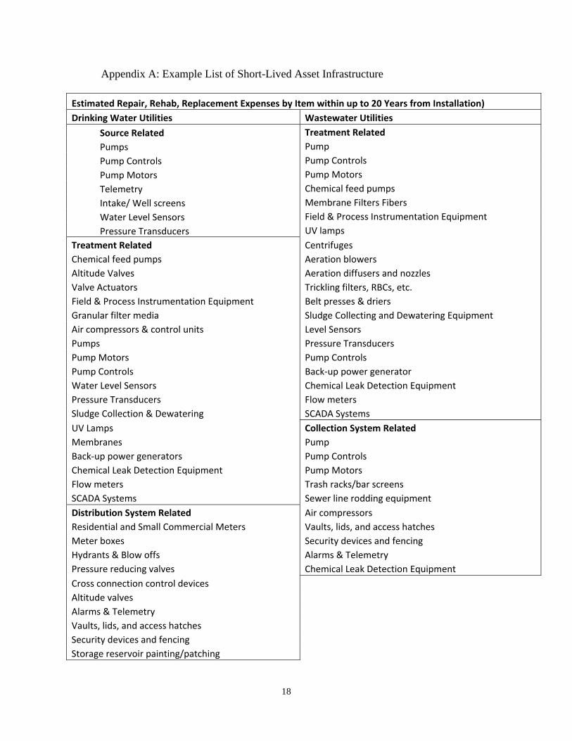
Appendix A: Example List of Short-Lived Asset Infrastructure
Estimated Repair, Rehab, Replacement Expenses by Item within up to 20 Years from Installation)
Drinking Water Utilities Wastewater Utilities
Source Related Pumps Pump Controls Pump Motors Telemetry Intake/ Well screens Water Level Sensors Pressure Transducers
Treatment Related Pump Pump Controls Pump Motors Chemical feed pumps Membrane Filters Fibers Field & Process Instrumentation Equipment UV lamps
CentrifugesTreatment Related Chemical feed pumps Aeration blowers Altitude Valves Aeration diffusers and nozzles Valve Actuators Trickling filters, RBCs, etc. Field & Process Instrumentation Equipment Belt presses & driers Granular filter media Sludge Collecting and Dewatering Equipment Air compressors & control units Level Sensors Pumps Pressure Transducers Pump Motors Pump Controls Pump Controls Back‐up power generator Water Level Sensors Chemical Leak Detection Equipment Pressure Transducers Flow meters Sludge Collection & Dewatering SCADA Systems
UV Lamps Collection System Related Membranes Pump Back‐up power generators Pump Controls Chemical Leak Detection Equipment Pump Motors Flow meters Trash racks/bar screens SCADA Systems Sewer line rodding equipment
Air compressors Distribution System Related Residential and Small Commercial Meters Vaults, lids, and access hatches Meter boxes Security devices and fencing Hydrants & Blow offs Alarms & Telemetry Pressure reducing valves Chemical Leak Detection Equipment
Cross connection control devices Altitude valves Alarms & Telemetry Vaults, lids, and access hatches Security devices and fencing Storage reservoir painting/patching
18
DWR-NPDES/SOP-G-01-WW Design Criteria Chapter 1-110117 Design Criteria for Review of Sewage Works Construction Plans and Documents
Chapter 1
November 1, 2017
APPENDIX 1-E-2
RECOMMENDED FACILITIES PLAN OUTLINE –CLEAN WATER STATE REVOLVING FUND (CWSRF)
THIS CWSRF DOCUMENT FOLLOWING IS CURRENT AS OF THE DESIGN CRITERIA CHAPTER 1 EFFECTIVE DATE. APPLICANTS FOR SRF LOAN PROGRAMS SHOULD VERIFY THAT THE LATEST INSTRUCTIONS ARE COMPLIED WITH.

DWR-NPDES/SOP-G-01-WW Design Criteria Chapter 1-110117 Design Criteria for Review of Sewage Works Construction Plans and Documents
Chapter 1
November 1, 2017
THIS PAGE INTENTIONALLY LEFT BLANK
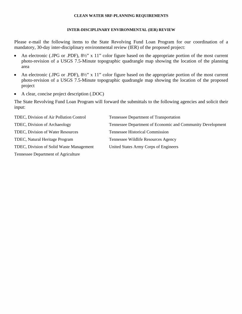
CLEAN WATER SRF-PLANNING REQUIREMENTS
INTER-DISCIPLINARY ENVIRONMENTAL (IER) REVIEW
Please e-mail the following items to the State Revolving Fund Loan Program for our coordination of a mandatory, 30-day inter-disciplinary environmental review (IER) of the proposed project:
An electronic (.JPG or .PDF), 8½” x 11” color figure based on the appropriate portion of the most current photo-revision of a USGS 7.5-Minute topographic quadrangle map showing the location of the planning area
An electronic (.JPG or .PDF), 8½” x 11” color figure based on the appropriate portion of the most current photo-revision of a USGS 7.5-Minute topographic quadrangle map showing the location of the proposed project
A clear, concise project description (.DOC)
The State Revolving Fund Loan Program will forward the submittals to the following agencies and solicit their input:
TDEC, Division of Air Pollution Control Tennessee Department of Transportation
TDEC, Division of Archaeology Tennessee Department of Economic and Community Development
TDEC, Division of Water Resources Tennessee Historical Commission
TDEC, Natural Heritage Program Tennessee Wildlife Resources Agency
TDEC, Division of Solid Waste Management United States Army Corps of Engineers
Tennessee Department of Agriculture

RECOMMENDED FACILITIES PLAN OUTLINE—CWSRF
The following is a suggested outline for the presentation of the required information for a Clean Water State Revolving Fund Facilities Planning document. Some of the information requested may not be applicable for certain projects.
1. SUMMARY, CONCLUSIONS, AND RECOMMENDATIONS 1.1 Statement of the Problem 1.2 Summary of the Alternative Solutions Considered 1.3 Recommended Solution
2. PURPOSE AND NEED 2.1 Study Purpose 2.2 Need for the Project
3. GENERAL INFORMATION 3.1 Existing Facilities and Area Served 3.2 Optimum Performance Available with the Existing Facilities/Operational Problems 3.3 Existing Collection System (indicate collectors, pumping stations, force mains, and WWTPs) 3.4 Potential for Serving Additional Areas
4. INFILTRATION AND INFLOW 4.1 Analysis of Infiltration and Inflow 4.2 Steps Being Taken to Reduce Excessive Infiltration and Inflow
5. FUTURE CONDITIONS 5.1 Planning Period (20 years) 5.2 Land Use Projections 5.3 Population Forecast
6. DEVELOPMENT OF ALTERNATIVES 6.1 “No Action” Alternative 6.2 Minimum of Three Alternatives in Addition to the “No Action” Alternative Compared For Cost- effectiveness,
Water and Energy Efficiency, Environmental Impacts, and Feasibility 6.3 Chosen Alternative
7. SELECTED PLAN DESCRIPTION 7.1 Detailed Description of Chosen Alternative 7.2 Fiscal Sustainability 7.3 Public Involvement/Public Meeting
8. PROJECT COSTS 8.1 Estimated Construction Costs and Overall Project Costs 8.2 Proposed Financing 8.3 Projected Operating Costs and User Charge Structure
9. ENVIRONMENTAL IMPACTS 9.1 Planning Area and Project Area (indicated on USGS quad map) and a Brief Project Description 9.2 Project Specific Impacts
10. ENVIRONMENTAL JUSTICE CONCERNS 10.1 Identification of Minority and Low-Income Populations in Project Area 10.2 Evaluation of Disproportionate Risks to Identified EJ Populations 10.3 Identification of Public Participation Opportunities for Identified EJ Populations 10.4 Evaluation of Environmental/Health Risks among Identified EJ Populations that may be Exacerbated by Proper
Construction and Operation of the Selected Alternative
Maps and Figures
APPENDICES (supporting documentation as appropriate)
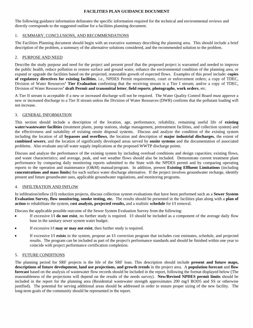
FACILITIES PLAN GUIDANCE DOCUMENT
The following guidance information delineates the specific information required for the technical and environmental reviews and directly corresponds to the suggested outline for a facilities planning document.
1. SUMMARY, CONCLUSIONS, AND RECOMMENDATIONS
The Facilities Planning document should begin with an executive summary describing the planning area. This should include a brief description of the problem, a summary of the alternative solutions considered, and the recommended solution to the problem.
2. PURPOSE AND NEED
Describe the study purpose and need for the project and present proof that the proposed project is warranted and needed to improve the public health, reduce pollution to restore surface and ground water, enhance the environmental condition of the planning area, or expand or upgrade the facilities based on the projected, reasonable growth of expected flows. Examples of this proof include: copies of regulatory directives for existing facilities, i.e., NPDES Permit requirements, court or enforcement orders; a copy of TDEC, Division of Water Resources’ Tier Evaluation confirming that the receiving stream is a Tier I stream; and/or a copy of TDEC, Division of Water Resources’ draft Permit and transmittal letter; field reports, photographs, work orders, etc.
A Tier II stream is acceptable if a new or increased discharge will not be required. The Water Quality Control Board must approve a new or increased discharge to a Tier II stream unless the Division of Water Resources (DWR) confirms that the pollutant loading will not increase.
3. GENERAL INFORMATION
This section should include a description of the location, age, performance, reliability, remaining useful life of existing water/wastewater facilities (treatment plants, pump stations, sludge management, pretreatment facilities, and collection system) and the effectiveness and suitability of existing onsite disposal systems. Discuss and analyze the condition of the existing system including the location of all bypasses and overflows, the location and description of major industrial discharges, the extent of combined sewers, and the location of significantly developed areas served by onsite systems and the documentation of associated problems. Also evaluate any/all water supply implications at the proposed WWTP discharge points.
Discuss and analyze the performance of the existing system by including overload conditions and design capacities; existing flows, and waste characteristics; and average, peak, and wet weather flows should also be included. Demonstrate current treatment plant performance by comparing daily monitoring reports submitted to the State with the NPDES permit and by comparing operating reports to the operation and maintenance (O&M) manual/program. In addition, present Existing Effluent Limitations (including concentrations and mass limits) for each surface water discharge alternative. If the project involves groundwater recharge, identify present and future groundwater uses, applicable groundwater regulations, and monitoring programs.
4. INFILTRATION AND INFLOW
In infiltration/inflow (I/I) reduction projects, discuss collection system evaluations that have been performed such as a Sewer System Evaluation Survey, flow monitoring, smoke testing, etc. The results should be presented in the facilities plan along with a plan of action to rehabilitate the system, cost analysis, projected results, and a realistic schedule for I/I removal.
Discuss the applicable possible outcome of the Sewer System Evaluation Survey from the following: If excessive I/I do not exist, no further study is required. I/I should be included as a component of the average daily flow
base in the sanitary sewer system water budget.
If excessive I/I may or may not exist, then further study is required.
If excessive I/I exists in the system, propose an I/I correction program that includes cost estimates, schedule, and projected results. The program can be included as part of the project's performance standards and should be finished within one year to coincide with project performance certification completion.
5. FUTURE CONDITIONS
The planning period for SRF projects is the life of the SRF loan. This description should include present and future maps, descriptions of future development, land use projections, and growth trends in the project area. A population forecast and flow forecast based on the analysis of wastewater flow records should be included in the report, following the format displayed below (The reasonableness of the projections will depend on the results of the needs survey). New/Revised NPDES permit limits should be included in the report for the planning area (Residential wastewater strength approximates 200 mg/l BOD5 and SS or otherwise justified). The potential for serving additional areas should be addressed in order to ensure proper sizing of the new facility. The long-term goals of the community should be represented in the report.
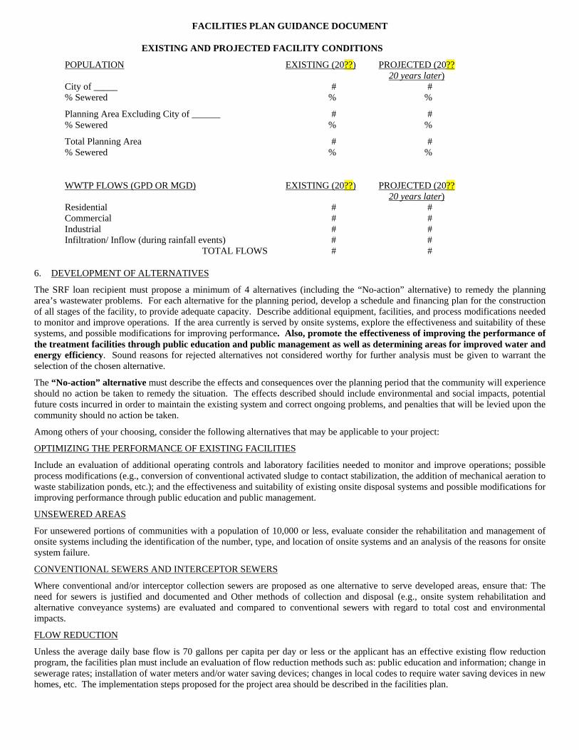
FACILITIES PLAN GUIDANCE DOCUMENT
EXISTING AND PROJECTED FACILITY CONDITIONS
POPULATION EXISTING (20??) PROJECTED (20?? 20 years later)
City of _____ # # % Sewered % %
Planning Area Excluding City of ______ # # % Sewered % %
Total Planning Area # # % Sewered % %
WWTP FLOWS (GPD OR MGD) EXISTING (20??) PROJECTED (20?? 20 years later)
Residential # # Commercial # # Industrial # # Infiltration/ Inflow (during rainfall events) # #
TOTAL FLOWS # #
6. DEVELOPMENT OF ALTERNATIVES
The SRF loan recipient must propose a minimum of 4 alternatives (including the “No-action” alternative) to remedy the planning area’s wastewater problems. For each alternative for the planning period, develop a schedule and financing plan for the construction of all stages of the facility, to provide adequate capacity. Describe additional equipment, facilities, and process modifications needed to monitor and improve operations. If the area currently is served by onsite systems, explore the effectiveness and suitability of these systems, and possible modifications for improving performance. Also, promote the effectiveness of improving the performance of the treatment facilities through public education and public management as well as determining areas for improved water and energy efficiency. Sound reasons for rejected alternatives not considered worthy for further analysis must be given to warrant the selection of the chosen alternative.
The “No-action” alternative must describe the effects and consequences over the planning period that the community will experience should no action be taken to remedy the situation. The effects described should include environmental and social impacts, potential future costs incurred in order to maintain the existing system and correct ongoing problems, and penalties that will be levied upon the community should no action be taken.
Among others of your choosing, consider the following alternatives that may be applicable to your project:
OPTIMIZING THE PERFORMANCE OF EXISTING FACILITIES
Include an evaluation of additional operating controls and laboratory facilities needed to monitor and improve operations; possible process modifications (e.g., conversion of conventional activated sludge to contact stabilization, the addition of mechanical aeration to waste stabilization ponds, etc.); and the effectiveness and suitability of existing onsite disposal systems and possible modifications for improving performance through public education and public management.
UNSEWERED AREAS
For unsewered portions of communities with a population of 10,000 or less, evaluate consider the rehabilitation and management of onsite systems including the identification of the number, type, and location of onsite systems and an analysis of the reasons for onsite system failure.
CONVENTIONAL SEWERS AND INTERCEPTOR SEWERS
Where conventional and/or interceptor collection sewers are proposed as one alternative to serve developed areas, ensure that: The need for sewers is justified and documented and Other methods of collection and disposal (e.g., onsite system rehabilitation and alternative conveyance systems) are evaluated and compared to conventional sewers with regard to total cost and environmental impacts.
FLOW REDUCTION
Unless the average daily base flow is 70 gallons per capita per day or less or the applicant has an effective existing flow reduction program, the facilities plan must include an evaluation of flow reduction methods such as: public education and information; change in sewerage rates; installation of water meters and/or water saving devices; changes in local codes to require water saving devices in new homes, etc. The implementation steps proposed for the project area should be described in the facilities plan.
FACILITIES PLAN GUIDANCE DOCUMENT
ALTERNATIVE CONVEYANCE SYSTEMS AND TECHNOLOGIES
If an alternative conveyance system or alternative technology is proposed, the applicant must demonstrate that the process is proven and is the best possible solution for the problem. Provide documentation from other examples that the expected treatment results are within normal ranges and will meet effluent standards. Alternative technologies should be compared to conventional ones and evaluated with regard to total cost and environmental impacts. For projects that include the construction of alternative collection sewers, ensure justification of the need to abandon existing onsite systems. In addition, the applicant should consider using existing septic tanks and conveyance of treated wastewater by small sewers or consider the development of a septage management program.
LAND APPLICATION SYSTEMS
If land application is proposed, the loan applicant must ensure that the following key factors are adequately addressed in accordance with EPA's process design manual. The plan should identify suitable sites for land application. Preliminary design values that conflict with those in EPA's process design manual for loading an area should be justified by adequate supporting data. Preliminary land treatment costs should be compared to referenced costs. Document significant differences in land costs.
SLUDGE DISPOSAL
Several alternatives regarding sludge treatment and disposal must be given. The alternatives evaluated should be appropriate as to size and location of the project. Consideration concerning sludge recycling and reclamation must be made. In addition, proposed sludge treatment and disposal methods must comply with regulatory requirements.
SMALL COMMUNITIES
For small communities of 10,000 people or less, low cost technologies such as facultative ponds, trickling filters, oxidation ditches, land-disposal, rehabilitation and management of onsite systems, etc., should be evaluated. In the case of onsite systems, the applicant must identify the number, type, and location of systems in the area. An analysis of reasons for onsite systems failure should be included, along with accompanying laboratory results, work orders, and other documentation showing that the existing system provides a health/environmental risk.
7. SELECTED PLAN DESCRIPTION
All major system components of the selected plan must be included in description of the chosen alternative, along with reasonable cost estimates. The design parameters must comply with State standards, as listed in “Tennessee Clean Water Design Criteria for Sewage Works.” The process and design must be capable of meeting applicable effluent limitations, such as the new/revised NPDES Permit (planning limits).
Determine the chosen alternative by employing a logical methodology that includes monetary evaluation, engineering evaluation, environmental impacts, public involvement, and implementation. The monetary evaluation should consider present or annual worth, useful life, interest during construction, construction staging, salvage value, replacement costs, capital costs, design, administrative, and construction costs. Projected operations and maintenance costs should be estimated and compared to the user charge structure implemented by the applicant. Also include proposed financing, including SRF Loan awards, local funding, various grants, etc., in the discussion.
The chosen alternative should also include an evaluation of the wastewater treatment works for areas of improved water and energy efficiency and implement these conservation efforts to the maximum extent practicable with the selected alternative.
The selected plan should discuss reliability, fiscal sustainability, and process complexity. For example, describe revenue generating applications, reduction or recovery of energy, water efficiency, reuse of treated wastewater, or other relevant factors.
The environmental impacts section should include a USGS quad map of the planning and project area (may be same map as that in the General Information section), a brief project description, and project-specific impacts.
Public Involvement is a crucial factor in project planning; therefore, SRF requires loan recipients to schedule a public meeting prior to facilities plan approval. A Public Meeting must be held to inform the public of the salient aspects of the planned project and to provide interested parties with an opportunity to comment. The Public Meeting must be advertised at least 14 days prior to the meeting date in order to maximize public participation. Advertise the meeting by using a minimum of one of the following means: publish in a local newspaper, post at banks, grocers, post offices, public libraries, city hall, etc., air on local television and/or radio stations, or insert with monthly utility bills. The advertisement must include the meeting date, time, and location, must specify the amount of the proposed loan, and state that the loan will impact the monthly sewer fees. The meeting must be scheduled on weekday evenings after 6:00 p.m. or on weekends in order to provide the public with the maximum attendance opportunity.
Topics to be discussed at the public meeting are, but not limited to, a complete description of the project, the project schedule, short-term impact verses long-term benefits, the total project cost to include the amounts of the potential SRF loan and other funding sources, and the project’s impact on sewer user fees regarding the repayment of the Clean Water State Revolving Fund loan. Submissions to the SRF Loan Program must include an account of the public meeting (transcript, audio, or video recording, etc.); a written summary of the meeting; a Sign-in Sheet (if available); a copy of the published advertisement and Publisher’s Affidavit from the newspaper, radio station, or television; and/or a copy or photo(s) of the actual advertisement posting, bill insert, or website address.
FACILITIES PLAN GUIDANCE DOCUMENT
Implementation of the project must be feasible. Include inter-municipal service agreements or memoranda of understanding, where applicable.
8. PROJECT COSTS
Projected costs for all alternatives must be tabulated and evaluated. Include present or annual worth, useful life, interest during construction, construction staging, salvage value, replacement costs, capital costs, design, administrative, construction costs, and projected operations and maintenance costs.
9. ENVIRONMENTAL IMPACTS
This section describes the existing environmental and facilities characteristics of the planning area. A location map of the project area, such as the one used for the Interdisciplinary Environmental Review, is a useful figure to include in this section. This map is typically a 7.5 Minute USGS Topographic Quadrangle Map with scale, north arrow, project name, and location labeled on the map.
Environmental Characteristics of the area should be described in detail in this portion of the planning document. Include information about land use, future development, growth trends in the project area, and pertinent figures/maps. The Topography and Hydrology of the area need to be addressed by describing the project area’s typical landscape, surface and ground water issues (quantity, quality, and users), and ground water aquifers. The Geologic description of the area should include the major geological features in the project area and the physiographical province in which the project is located. Describe the physical properties of the soils by defining the general soil types of the project area and explaining their structural limitations and physical properties, when applicable. If possible, include soil maps of the area.
Historical and Archeological Features of the area need to be researched carefully during the planning stage. Clearance letters from the Historical Commission and other appropriate Federal and State agencies should be included in this section. Items concerning Cultural Resources and Agricultural Lands need to be addressed. Provisions to avoid disturbance or damages to historical or archaeological sites during construction activities, and avoidance of adverse effects to prime and/or unique agricultural land should be described in this section. In addition, residential areas near the proposed location should be recognized in the planning process. Measures to avoid significantly displacing population and altering the character of existing residential neighborhoods should be mentioned in this section of the planning document.
The Water Supply of the planning area should be described in detail. Ground sources of water and any possible contamination of water supply by the proposed project need to be described. Location of points of water withdrawal should be researched and reported. Wild and Scenic Rivers should be avoided, as should degradation of Fish and Wildlife habitats. Endangered Species in the area also need to be protected. Describe the flora and fauna in the planning area (particularly downstream from the proposed discharge point), and include a list of endangered species in the project area. Identify, locate, and describe the Wetlands in the project area. Minimize adverse effects during stream crossings by employing best management practices described in the facilities plan. Required permitting (such as ARAP, TVA, US Army COE, etc.) should be mentioned in this section, and the loan recipient should work to secure these permits. Floodplain Issues must be addressed. Include a floodplain map indicating project location, and indicate if the project will be subject to flooding. Aboveground portions of the project must be flood-proofed to the 100-year flood elevation. The general overall Air Quality of the planning area and measures taken to avoid adverse effects by the proposed project on ambient air quality should be described.
Remedial Actions will need to be taken to ensure the best possible environmental conditions during and after construction. Describe the best management practices (BMPs) that will be employed to reduce noise, dust, odor, erosion, and sedimentation from construction activities.
10. ENVIRONMENTAL JUSTICE CONCERNS
Has any minority or low-income populations been identified within the project area?
Does the selected alternative present disproportionate risks to the minority or low-income populations identified within the project area?
Have the minority or low-income populations identified within the project area been provided an opportunity for public participation?
Do the minority or low-income populations identified within the project area suffer from environmental/health risks that will be exacerbated by the proper construction and operation of the selected alternative?
MAPS AND FIGURES
Topographic map with project area defined (8½” x 11” ) Map/Figure of City limits and planning/service area (8½” x 11”)
APPENDICES

FACILITIES PLAN GUIDANCE DOCUMENT
ADDITIONAL REQUIRED DOCUMENTS FOR FACILITES PLAN APPROVAL
A copy of the Plan of Operation or “In Lieu of” letter for FP approval
Appendix 1-F
Corrective Action Plan/Engineering Report (CAP/ER) Guidance
A CAP/ER is usually assigned as one of the first action items in a Commissioner’s or Director’s Order or an Agreed Consent Order with accompanying contingent penalty. Submission in the prescribed time frame is the responsibility of the permit holder but as it contains an engineering report required to be prepared by a registered engineer, it is often submitted by an engineer on behalf of the permit holder.
The CAP is first and foremost a plan that delineates:
1. all action steps prescribed by the order whether requiring engineering outlined in the PER or not, as well as, necessary intermediate steps to achieve the required results,
2. the responsible parties for the action, 3. deadlines prescribed in the order, as well as, those intermediate deadlines necessary for successful
achievement of compliance with the order and permit, and 4. estimates of costs other than the contingent fines of the required order elements.
The plan should be organized in such a way that the achievement of all ordered deadlines is clearly included and also presented in chronological order of anticipated achievement.
The CAP may be submitted by the permit holder and reference the accompanying engineering report submitted simultaneously under the engineer’s seal.
The engineering report in the CAP/ER may be more akin to the federal agency prescribed requirements in the USDA/USEPA/HUD/IHS Interagency Memorandum included as Appendix 1-E-1 in this Criteria for Preliminary Engineering Reports (PERs) than the Engineering Report (ER) the details of which are included in the main body of this chapter and Appendix 1-D-2. The Order should specify the format and any specific issues to be addresses unique to the situation. If the permit holder and engineer determine that the corrective solution requires only the repair of existing equipment, the replacement in kind of existing equipment or, if there is clearly only one course of action appropriate to correct the situation addressed in the order, a CAP/ER should be specified. The PER format should be specified when the requirements for multiple alternative analyses on a life cycle cost basis is appropriate.
A CAP/PER prescribed by the Director or Commissioner need not address the outline items 6) f) iii) Debt Repayments, or iv) Reserves.

THIS PAGE INTENTIONALLY LEFT BLANK
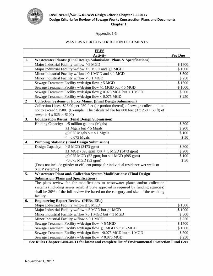
DWR-NPDES/SOP-G-01-WW Design Criteria Chapter 1-110117 Design Criteria for Review of Sewage Works Construction Plans and Documents
Chapter 1
November 1, 2017
Appendix 1-G
WASTEWATER CONSTRUCTION DOCUMENTS
FEES Activity Fee Due
1. Wastewater Plants: (Final Design Submission: Plans & Specifications) Major Industrial Facility w/flow ≥5 MGD $ 1500 Major Industrial Facility w/flow < 5 MGD and ≥1 MGD $ 1000 Minor Industrial Facility w/flow ≥0.1 MGD and < 1 MGD $ 500 Minor Industrial Facility w/flow < 0.1 MGD $ 250 Sewage Treatment Facility w/design flow ≥ 5 MGD $ 1500 Sewage Treatment Facility w/design flow ≥1 MGD but < 5 MGD $ 1000 Sewage Treatment Facility w/design flow ≥ 0.075 MGD but < 1 MGD $ 500 Sewage Treatment Facility w/design flow < 0.075 MGD $ 250 2 Collection Systems or Force Mains: (Final Design Submission) Collection Lines: $25.00 per 250 feet (or portion thereof) of sewage collection line
not to exceed $1500. (Example: The calculated fee for 800 feet (3 x 250 + 50 ft) of sewer is 4 x $25 or $100)
3. Equalization Basins: (Final Design Submission) Holding Capacity: ≥5 million gallons (Mgals) $ 300 ≥1 Mgals but < 5 Mgals $ 200 ≥0.075 Mgals but < 1 Mgals $ 100 < 0.075 Mgals $ 50 4. Pumping Stations: (Final Design Submission) Design Capacity: ≥ 5 MGD (3473 gpm) $ 300 ≥1 MGD (695 gpm) but < 5 MGD (3473 gpm) $ 200 ≥0.075 MGD (52 gpm) but < 1 MGD (695 gpm) $ 100 <0.075 MGD (52 gpm)
(Does not include grinder or effluent pumps for individual residence wet wells or STEP systems.)
$ 50
5. Wastewater Plant and/ Collection System Modifications: (Final Design Submission (Plans and Specifications)
The plans review fee for modifications to wastewater plants and/or collection systems (including sewer rehab if State approval is required by funding agencies) shall be 20% of the full review fee based on the category and size of the resulting facility.
6. Engineering Report Review (PERs, ERs) Major Industrial Facility w/flow ≥ 5 MGD $ 1500 Major Industrial Facility w/flow < 5 MGD but ≥1 MGD $ 1000 Minor Industrial Facility w/flow ≥0.1 MGD but < 1 MGD $ 500 Minor Industrial Facility w/flow < 0.1 MGD $ 250 Sewage Treatment Facility w/design flow ≥ 5 MGD $ 1500 Sewage Treatment Facility w/design flow ≥1 MGD but < 5 MGD $ 1000 Sewage Treatment Facility w/design flow ≥0.075 MGD but < 1 MGD $ 500 Sewage Treatment Facility w/design flow < 0.075 MGD $ 250
See Rules Chapter 0400-40-11 for latest and complete list of Environmental Protection Fund Fees

DWR-NPDES/SOP-G-01-WW Design Criteria Chapter 1-110117 Design Criteria for Review of Sewage Works Construction Plans and Documents
Chapter 1
November 1, 2017
Cover Letter/Submittal Transmittal with construction documents covered by the Design Criteria:
• If the letter is signed by a representative of an engineering firm, rather than the current or perspective owner/permit holder, then the letter should state in the first sentence clearly for whom the documents are submitted AND the permit holder copied.
• Reference the current or perspective owner, permit number if applicable, name of project, location by county and/or city in the subject heading.
• Describe the type project and scope. (e.g., 16 MGD municipal wastewater treatment plant; 16,000 LF of gravity sewer, 5 MGD dry well mounted dual submersible pump station, 1400 LF of 8” diameter ductile force main; 50,000 gpd recirculating sand filter with 10 acres of drip emitter land application)
• Contact person: name, email, address, phone number, and fax number. • Attached or accompanying documents and format. (e.g., 1 full size set of plans and CD with
plans, specifications and engineering report) • Names, companies/employers, addresses and emails for other individuals to receive responses to
final review determination.
Fee submittals:
• If Engineering Report and Preliminary Plans are submitted at the end of the preliminary design phase (for all conventional treatment plants (TF), decentralized treatment plants (DC), land application projects (LA), and reuse projects (RU)) to:
Division of Water Resources Wastewater Construction Documents and Reports 11th Floor - William R Snodgrass TN Tower 312 Rosa L Parks Avenue Nashville TN 37243-1102 Or [email protected]
o Enclose appropriate engineering report review fees based on item #6 categories above with the preliminary design submittal.
o Enclose appropriate plans and specs review fees based on item # 1 categories above with the final design submittal.
• If Engineering Report or Summary Design Form with Technical Calculations and Documents, Final Plans, Specifications are submitted in a final design submittal (for all sewer lift station (SLS), force main (FM), gravity collection system piping (GR) projects; note that currently engineering report review fees are not required for non-treatment projects and that purely sewer rehab projects are not required to be reviewed by TDEC-DWR.):
o Enclose appropriate plans and specs review fees from item 1-5. • PERs or other stand-alone engineering reports involving treatment operations (classified by codes
TF, DC, IW, or LA in accordance with the legend in Appendix 1-D-1; Enclose appropriate
DWR-NPDES/SOP-G-01-WW Design Criteria Chapter 1-110117 Design Criteria for Review of Sewage Works Construction Plans and Documents
Chapter 1
November 1, 2017
engineering report fees for appropriate sized facility in line item #6 above. For PERs not itemized in item #6 (e.g., for funding agency application), a $250 review fee is required.
Copies and format: Electronic format may be agreed upon at Preliminary Project Discussion; CD, DVD, and internet transfer may be acceptable if sealed documents are provided. When submitted electronically, plan sheets must be in pdf format and completely legible when printed on legal size paper (11”x17”), and engineering reports and specifications must be in pdf or word processing format and capable of being read by optical character recognition (OCR) programs, as well as, being legible. Documents provided on CD are preferred; please do not provide more than 4 paper copies of any documents to be returned. Funding agencies may require additional documentation. Note that one complete State-approved full-size set of construction documents, i.e., plans, specifications, state approved changes or addenda, must still be on the construction site and available during inspections until the project is commissioned. Record drawings are required to be submitted to TDEC-DWR on all wastewater treatment projects including conventional plants (TF), decentralized plants (DC), industrial wastewater treatment and land application sites (LA) and strongly encouraged to be provided to the owner on all projects .
• Preliminary Design Submittal: o Cover letter: One paper copy with review fees and worksheet attached. o Plans: One or more copies half (11”x17”) or full size (nominal 22”x34” or larger) paper
submission AND/OR electronically submitted; annotated “FOR REVIEW AND NOT CONSTRUCTION” paper copies will be returned stamped if requested; electronically submitted plans will be returned with electronic approval stamp.
o Engineering Report: One or more 8 ½ x 11 paper copies with color figures AND/OR electronic version legible when printed on 8 ½ x 11 paper; seal affixed paper copies if requested will be returned stamped; electronically submitted engineering report will be returned with electronic approval stamp.
• Final Design Submittal: o Cover letter: One paper copy with review fees and worksheet attached. o Plans: One or more copies full size paper submission AND electronic submission sealed
by engineer of record. Paper copies will be returned stamped for use at construction site; electronically submitted plans will be returned with electronic approval stamp and copy retained.
o Engineering Report if not previously submitted: One or more 8 ½ x 11 paper copies with color figures AND/OR electronic version legible when printed on 8 ½ x 11 paper; seal affixed; Paper copies if requested will be returned stamped; electronically submitted engineering report will be returned with electronic approval stamp and file copy retained.
o Specifications: One or more 8 ½ x 11 paper copies with color figures AND/OR electronic version legible when printed on 8 ½ x 11 paper; seal affixed. Paper copies if requested will be returned stamped; electronically submitted specifications will be returned with electronic approval stamp and file copy retained.
• Preliminary Engineering Report (PER) Submittal:

DWR-NPDES/SOP-G-01-WW Design Criteria Chapter 1-110117 Design Criteria for Review of Sewage Works Construction Plans and Documents
Chapter 1
November 1, 2017
o One or more 8 ½ x 11 paper copies with color figures AND/OR electronic version legible when printed on 8 ½ x 11 paper; seal affixed. Paper copies if requested will be returned stamped; electronically submitted engineering report will be returned with electronic approval stamp and file copy retained.
• Record (as-built) Drawings o Electronic submission with record drawing signature on all sheets.
Related Documents


