Design, Construction, Installation and first Commissioning Results of the LHC Cryogenic System Serge Claudet (CERN, Geneva) On behalf of the “Cryogenics for Accelerator” group and the hundreds of people involved

Welcome message from author
This document is posted to help you gain knowledge. Please leave a comment to let me know what you think about it! Share it to your friends and learn new things together.
Transcript

Design, Construction, Installation and first
Commissioning Resultsof the
LHC Cryogenic SystemSerge Claudet (CERN, Geneva)
On behalf of the “Cryogenics for Accelerator” groupand the hundreds of people involved

S. Claudet - EPAC'06 Edinburgh LHC Cryogenic system: 1st experience
Thanks to contributors
• A. Ballarino• Ch. Balle• J. Casas• J-P. Delahaye• G. Ferlin• Ph. Gayet• Ph. Lebrun• F. Millet
• C. Parente• G. Riddone• L. Serio• L. Tavian• R. Van Weelderen• B. Vullierme• U. Wagner

S. Claudet - EPAC'06 Edinburgh LHC Cryogenic system: 1st experience
Content
• Introduction• Design challenges and R&D outcome• Procurement, Construction & Installation• First commissioning experience• Main problems encountered• Considerations for new projects• Conclusion
90ies
‘02 - ‘06‘98 - ‘06
S. Claudet - EPAC'06 Edinburgh LHC Cryogenic system: 1st experience
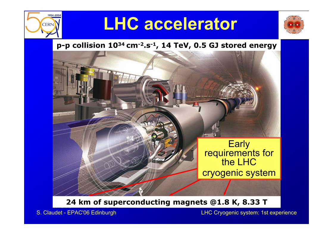
LHC accelerator
24 km of superconducting magnets @1.8 K, 8.33 T
p-p collision 1034 cm-2.s-1, 14 TeV, 0.5 GJ stored energy
Early requirements for
the LHCcryogenic system
S. Claudet - EPAC'06 Edinburgh LHC Cryogenic system: 1st experience
Layout of cryogenics
Pt 3
Pt 4
Pt 5
Pt 6
Pt 7
Pt 8
Pt 1
Pt 2
Pt 1.8
Cryoplant DistributionPresent Version
Cryogenic plant
8 x 18kW @ 4.5 K
1’800 sc magnets
24 km & 20 kW @ 1.8 K
36’000 t @ 1.9K
100 t He inventory

S. Claudet - EPAC'06 Edinburgh LHC Cryogenic system: 1st experience
Cryogenic architecture
Warm CompressorStation
Upper Cold Box
Interconnection Box
Cold Box
Warm CompressorStation
Lower Cold Box
Distribution Line Distribution Line
Magnet Cryostats Magnet Cryostats
Cold Compressorbox
Warm CompressorStation
Cold Compressorbox
Warm CompressorStation
Shaft
Surfa
ceC
aver
nTu
nnel
LHC Sector (3.3 km) LHC Sector (3.3 km)
1.8 K Refrigeration Unit New 4.5 K Refrigerator Ex-LEP 4.5 K refrigerator 1.8 K Refrigeration Unit
Typical LHC even point

S. Claudet - EPAC'06 Edinburgh LHC Cryogenic system: 1st experience
0
20
40
60
80
100
120
140
160
180
1960 1980 2000
Year
OMEGA,BEBC,
ISR Low-Beta
ALEPH,DELPHI,
LEP Low-Beta
LEP2
LHC, ATLAS, CMS
LEP2+
LHC
: 14
4 kW
LHCCooling capacity
How does it compare ?
Tevatron, RHIC,Jlab, SNS, HERA,
Tristan, …
ITER
0
50
100
150
200
250
300
Tevatr
on
HERA
CEBAF
RHIC
LEP2
LHC
(SSC)
[tonn
es]
VirtualLiquidGas @ 2 MPa
Helium Inventory
Unprecedented !
1
10
100
1000
10000
1 10
T [K]
P [k
Pa]
SOLID
HeII HeI
CRITICAL POINT
GAS
λ line
Saturated He II
Pressurized He II
1
10
100
1000
10000
1 10
T [K]
P [k
Pa]
SOLID
HeII HeI
CRITICAL POINT
GAS
λ line
Saturated He II
Pressurized He II
Superfluid Helium 1.8 K

S. Claudet - EPAC'06 Edinburgh LHC Cryogenic system: 1st experience
Design
• Site constraints and general concerns
• Early heat load inventory and follow-up, periodic update of cryogenic architecture
• Components and system R&D:– Early industry involvement– Dedicated tests facilities

S. Claudet - EPAC'06 Edinburgh LHC Cryogenic system: 1st experience
Magnet cooling scheme
1
10
100
1000
10000
1 10
T [K]
P [k
Pa]
SOLID
HeII HeI
CRITICAL POINT
GAS
λ line
Saturated He II
Pressurized He II
1
10
100
1000
10000
1 10
T [K]
P [k
Pa]
SOLID
HeII HeI
CRITICAL POINT
GAS
λ line
Saturated He II
Pressurized He II
Thermo-hydraulics of two-phase flow
in He II
(and limitations!)
(≈ 1W/m)

S. Claudet - EPAC'06 Edinburgh LHC Cryogenic system: 1st experience
1.8 K issues
CC:- 3D wheels- Bearings (300K)HX:- Very Low Pressure
CC
CC
CC
LHe
Sub-atmosphericcompressor
4.5
K re
frige
rato
r
Heat load
HP
MP
LP
1
2
3
“Mixed” Compression P ratio ≈ 80
HX Stainless Steel Plate
Axial-centrifugalImpeller (3D)
Fixed-vanediffuser
3-phase inductionElectrical motor(rotational speed: 200 to 700 Hz)
Activemagneticbearings
300
K un
der
atm
osph
ere
Cold
und
erva
cuum
Inlet
Outlet
Pressure ratio2 to 4
Spiral volute
200 to 800 Hz)
Cold Compressor

S. Claudet - EPAC'06 Edinburgh LHC Cryogenic system: 1st experience
Thermometry6’000 units, +/- 10 mK @ 2K in LHC radiation conditions
From ‘sensor’ to ‘thermometer’ with signal processing

S. Claudet - EPAC'06 Edinburgh LHC Cryogenic system: 1st experience
Other R&D examples
• HTS current leadsTotal: 3.4 MA
1200 units600-6000-13000 A
BSCCO 2223
• Thermal design:– Low temperature insulation– Heat intercept techniques
20 l/m @ 1.9 K 100 m3 @ 20 K 2000 m3@ 300 K
• Safe cryo-magnets resistive transition:– Cascade: cryostat - cold recovery header - MP tanks– Specific cold safety relief valves

S. Claudet - EPAC'06 Edinburgh LHC Cryogenic system: 1st experience
LHC test string
More than 20’000 hours of operation of the LHC Test Strings
1.7
1.75
1.8
1.85
1.9
1.95
2
10:50 11:00 11:10 11:20 11:30 11:400
2
4
6
8
10
12[kA], W/m[K]
0.2 W/m 0.3 W/m - 0.6 nOhm
T stability duringMagnet powering
0
5
10
15
20
25
30
35
0 20 40 60 80 100 120 140 160 180
time,s
[K],
[bar
], [V
]
0
2
4
6
8
10
12
QV9202SIQV920
Quench MB5 , 37s
Quench MB6 , 72s
pressureT MB5
T MB6
T MB4
T MB1, MB2, MB3
P evolution during quench at 13’000 kA

S. Claudet - EPAC'06 Edinburgh LHC Cryogenic system: 1st experience
Procurement• Sub-systems by type of functionality:
– CERN to define interfaces and required performance
• Great majority procured from industry:– Competitive performance based tendering
– Detailed studies, manufacturing, site installation, commissioning, performance assessment
• Separate management of general services:– Interconnecting piping, controls

S. Claudet - EPAC'06 Edinburgh LHC Cryogenic system: 1st experience
Construction phase• Industry available products:
(storage tanks, piping, 4.5K refrigerators)– Functional technical specifications adapted (tests)
• Extension of existing products(1.8K units, cryogenic lines, electrical feed boxes)– Complex performance & possible impacts– CERN add. design & support to fabrication
• Totally new products(Rad. tol. cryo thermometry - superconducting links)– CERN with full responsibility for developments and
“built to print” fabrication contracts
Projects
OP

S. Claudet - EPAC'06 Edinburgh LHC Cryogenic system: 1st experience
Industrial fabrication sites
European abrication sites for LHC Cryogenics
And from USA, Russia, Japan, …
Main distribution line:Dedicated assembly sites to cope with ’’relative’’ modularity
215 standardpipe elements
30 fixed points & vacuum barriers
17 special service mod. + 1 return mod.
18 standardservice modules
2 double-jumper service module
30 special pipe elements
2 steps 6 elbows 1 test module
Important issues:Qualification, procedures, supply
chain, follow-up, Quality assurance

S. Claudet - EPAC'06 Edinburgh LHC Cryogenic system: 1st experience
Electrical feed boxes
Assembly of current leads cartridges
Final assembly and tests
Assembly of DFBM, DFBL, LCM
Assembly of DFBA HCM
Components
Assembly of the busbar bundles
Assembly of the Arc Termination Module (ATM)
Final assembly + tests
CL cartridges assembly area
CL modules assembly stands
Global leak test of DFBMPressure test area for DFBAs
Assembly of DFBA shuffling boxes
DFBA busbar bundles lambda plates
AT-ACR
IHEP / AT-ACR
TS-MME
ICS / AT
Towards an integrated factory !
Mechanics - Electricity - Cryogenics

S. Claudet - EPAC'06 Edinburgh LHC Cryogenic system: 1st experience
Installation phases
Helium storage tanks
Compressors
Cold Box close to access shaft
Powering sub-station
Cooling towers
Important issues: logistics, handling, co-activity, quality

S. Claudet - EPAC'06 Edinburgh LHC Cryogenic system: 1st experience
Installation & tests
Cryoplants
Interconnection box
MP storage< 20 bar
Purge line
TunnelCavernsSurface
Warm Recovery Line (WRL)
Vent
Lin
e (V
L) To atmosphere
B
E
D
C
F
QRL & Machine
Cold He with HPWarm He with HPWarm He with LPAir
Cold compressor box
PT
Equipment under installation already connected to cryogenic equipment under operation or commissioning …
- Tappings
- Two valves in series
- Padlocks

S. Claudet - EPAC'06 Edinburgh LHC Cryogenic system: 1st experience
Commissioning• Commissioning of each sub-system:
– Mechanical pressure test, helium leak test– Input/output signal tests– Operational tests to demonstrate all functions– Performance measurements (ref. capacity, thermal losses)
• Subsequent commissioning in cascade:– Potential problems identified early and clearly– Possible actions before it becomes critical
• Global LHC Hardware Commissioning:– A Crucial test for many systems, incl. cryogenics– Project wide coordination efforts, incl cryogenics
Projects
OP

S. Claudet - EPAC'06 Edinburgh LHC Cryogenic system: 1st experience
Magnet cold tests

S. Claudet - EPAC'06 Edinburgh LHC Cryogenic system: 1st experience
Cryogenic sub-systems
Point 8Storage
Sector 7-8 Sector 8-1
Surf
ace
Cav
ern
QSCA QSCB
QSRB
QURC
QUIC
QURA
Shaf
t
QSCC QSCC
Tunnel
QURC
QSRA

S. Claudet - EPAC'06 Edinburgh LHC Cryogenic system: 1st experience
18 kW @ 4.5 K Refrigerators33 kW @ 50 K to 75 K - 23 kW @ 4.6 K to 20 K - 41 g/s liquefaction
Pinput : 4.2 MW
Carnot Limit
COP
250 W/W

S. Claudet - EPAC'06 Edinburgh LHC Cryogenic system: 1st experience
2400 W @ 1.8K units
1.8K refrigeration units1st Pump-down in final LHC configuration
0.000.05
0.100.15
0.200.250.30
0.350.40
0.450.50
7:12 8:24 9:36 10:48 12:00
Time
0
500
1000
1500
2000
2500
Coo
ling
Pow
er [
W]
Suction Pressure
Set point
1.8K Cooling Power
P8 - 7 April 2005
Installed mode 2400 W @ 1.8 K
Pump-down 15 mbar
0
10
20
30
40
50
60
70
80
1985 1993 2000Year of construction
Isen
tropi
c ef
ficie
ncy
[%]
Tore SupraCEBAF
LHC
Diam: 250mm

S. Claudet - EPAC'06 Edinburgh LHC Cryogenic system: 1st experience
Main cryogenic line
634 +/- 50 (~0.2 W/m)
593
B+C+D (4-20 K)
9000 +/- 400 (~ 2.8 W/m)
Measured
9850Calculated
E+F (50-75 K)
Heat inleaks [W]

S. Claudet - EPAC'06 Edinburgh LHC Cryogenic system: 1st experience
Cryogenics P&F diagram
A large and complex fluid distribution system
More than 100 PIDcontrol loops
Towards modern predictive controls …

S. Claudet - EPAC'06 Edinburgh LHC Cryogenic system: 1st experience
Progress overview
Staggered progress by ‘‘LHC Point’’ then by sub-system

S. Claudet - EPAC'06 Edinburgh LHC Cryogenic system: 1st experience
Main problems !• Very specific “troubles” not even mentioned
• Design & sub-system concerns– Cryogenic lines ( x 3 )– Electrical heaters for cryogenic flows ( x 2 )– Impurities (dust) remaining from fabrication– Controls– Coordination for “built to print” sub-systems ( x 2 )
• General concerns– 3D models, transport items to place, QA tools– “Time is contingency” to “Keep on schedule” takes time!
S. Claudet - EPAC'06 Edinburgh LHC Cryogenic system: 1st experience
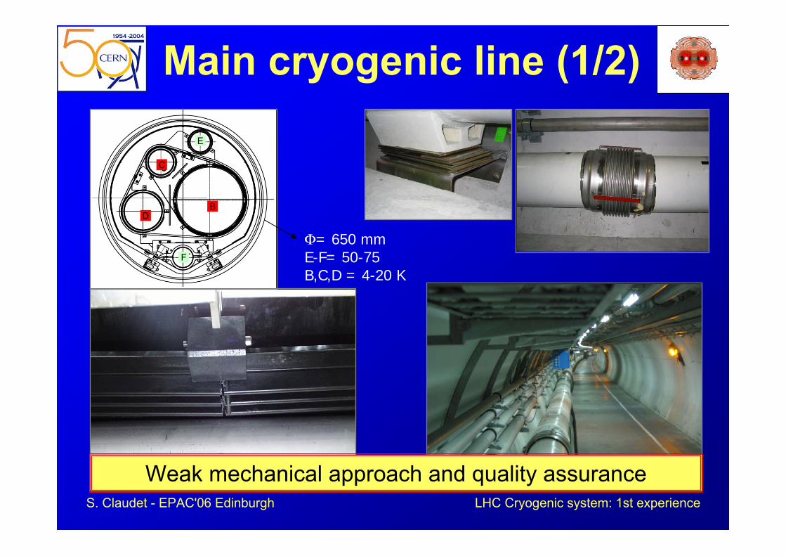
Main cryogenic line (1/2)E
F
BD
C
E
F
BD
C
Φ= 650 mmE-F= 50-75 B,C,D = 4-20 K
Weak mechanical approach and quality assurance

S. Claudet - EPAC'06 Edinburgh LHC Cryogenic system: 1st experience
Main cryogenic line (2/2)“C” type interconnections
“A” type interconnections
Special interconnections
2nd start has been the
good one, after
complements by CERN
Double sourcing ?

S. Claudet - EPAC'06 Edinburgh LHC Cryogenic system: 1st experience
Electrical heaters
Combination of heat exchange, flow patterns, electrical and
integration analysis
New design
Chicane Filler piece
Thermal screens
600 kW ElectricalHeater
D ≈ 500 mmL ≈ 3.5 m

S. Claudet - EPAC'06 Edinburgh LHC Cryogenic system: 1st experience
SH6
US IP6
SUH6
QURA-1
QSCA-1/2
QURCa-1
QSA(a)
QURCb-1
QSCCb
QSCB
QUI
QSDN
Ethernet backbone (IT-CS)
Ethernet surface Infrastucture (IT-CS)
Comp 4.5KComp 1.8K Comp 1.8K Comp 4.5K Main Dryer
QURCa-2
QURCb-2
QURA-2
QSRB-1/2Cold Box 4.5K LN2 BufferGhe Buffer
CB 1.8KCB 1.8K
LCB4.5K
ConnectionBox
SHM6 SD6
QSRA-1/2UCB 4.5K
Ethernet underground Infrastucture (IT-CS)
QSKAQSA(b)QSCCa QSV
Main Dryer
SCADA data servers
LHCALHCCa
LHCCb
LHCB
Ethernet local connection (LHC-IAS/IT CS)
1.8K 1.8K4.5K 4.5K
DS1 DS2
OS1OS2
OS3OS4
EW1
EW2230v
Alcove AlcoveUS IP5(b)
DFB
AlcoveAlcove US IP7(a)
DFB
Sector DFB
DFB
Sector
OS1OS2
OS3OS48 x 30 PLC’s
8 x 10’000 I/O
Controls
Industrial PLC’s, Ethernet based communications and object
oriented sofware:High potential, reliability being
improved

S. Claudet - EPAC'06 Edinburgh LHC Cryogenic system: 1st experience
Considerations for new projects
• LHC public documentation:• Each new project has its own constraints!
Identification of boundary conditions and technological evolution since last project:– Partnership: an efficient way to catch faster– If necessary, R&D and components validation
• For design & installation: solid referencescompleted by flexibility
• Take advantage of experienced teams while they exist!
www.cern.ch/lhc> LHC Design Report > Cryogenics> LHC Project Reports : Papers
S. Claudet - EPAC'06 Edinburgh LHC Cryogenic system: 1st experience
Conclusion
• Installation of various cryogenic sub-systems and cold tests of LHC cryo-magnets will be mostly completed by end of 2006
• All cryogenic sub-systems commissioned so farfulfil their requirements
• First LHC sector cool-down and commissioning end 2006:
Confident, and aware that it represents an enormous challenge with learning process, efforts and surprises!
Related Documents


