i DESIGN, CONSTRUCTION AND TESTING OF A COMPUTERIZED IGNITION CIRCUIT FOR AN INTERNAL COMBUSTION ENGINE A THESIS SUBMITTED TO THE GRADUATE SCHOOL OF NATURAL APPLIED SCIENCES OF MIDDLE EAST TECHNICAL UNIVERSITY BY NEVZAT ÇAKMAK IN PARTIAL FULLFILMENT OF THE REQUIREMENTS FOR THE DEGREE OF MASTER OF SCIENCE IN MECHANICAL ENGINEERING SEPTEMBER 2012

Welcome message from author
This document is posted to help you gain knowledge. Please leave a comment to let me know what you think about it! Share it to your friends and learn new things together.
Transcript

i
DESIGN, CONSTRUCTION AND TESTING OF A COMPUTERIZED IGNITION CIRCUIT FOR AN INTERNAL COMBUSTION ENGINE
A THESIS SUBMITTED TO THE GRADUATE SCHOOL OF NATURAL APPLIED SCIENCES
OF MIDDLE EAST TECHNICAL UNIVERSITY
BY
NEVZAT ÇAKMAK
IN PARTIAL FULLFILMENT OF THE REQUIREMENTS FOR
THE DEGREE OF MASTER OF SCIENCE IN
MECHANICAL ENGINEERING
SEPTEMBER 2012

ii
Approval of the thesis
DESIGN, CONSTRUCTION AND TESTING OF A COMPUTERIZED IGNITION CIRCUIT FOR AN INTERNAL COMBUSTION ENGINE
submitted by NEVZAT ÇAKMAK in partial fulfillment of the requirements for the degree of Master of Science in Mechanical Engineering Department, Middle East Technical University by, Prof. Dr. Canan Özgen Dean, Graduate School of Natural and Applied Sciences ________________ Prof. Dr. Süha Oral Head of Department, Mechanical Engineering ________________ Prof. Dr. A. Demir Bayka Supervisor, Mechanical Engineering Dept., METU ________________ Examining Committee Members: Prof. Dr. Tuna Balkan Mechanical Engineering Dept., METU ________________ Prof. Dr. A. Demir Bayka Mechanical Engineering Dept., METU ________________ Prof. Dr. Engin Kılıç Mechanical Engineering Dept., METU ________________ Assoc. Prof. Dr. Cemil Yamalı Mechanical Engineering Dept., METU ________________ Dr. Anıl Karel NUROL AŞ ________________ Date: 07.09.2012

iii
I hereby declare that all information in this document has been obtained and presented in accordance with academic rules and ethical conduct. I also declare that, as required by these rules and conduct, I have fully cited and referenced all material and results that are not original to this work.
Name, Last Name: Nevzat Çakmak
Signature :

iv
ABSTRACT
DESIGN, CONSTRUCTION AND TESTING OF A COMPUTERIZED IGNITION
CIRCUIT FOR AN INTERNAL COMBUSTION ENGINE
Çakmak, Nevzat
Department of Mechanical Engineering
Supervisor: Prof. Dr. A. Demir Bayka
September 2012, 192 pages
In this study, an ignition unit was designed and constructed for a new design engine
with eight cylinders and sixteen pistons. The ignition coils with two high voltage
outputs were used to ignite sixteen spark plugs on the system. They were driven by
PIC16F628A based igniter circuits triggered with digital signals. The igniter circuits
receive ignition signals in a square wave form from a main control circuit; they open
or close primary voltage of the induction coils to ignite spark plugs. This main
control circuit is based on PIC16F877A; and there are two of them. The duty of main
control circuit is to determine ignition advance according to engine speed and
cooling water temperature, and send proper ignition signals to the igniter circuits.
This main control circuit receives engine speed from the other main circuit
(secondary control circuit) with serial communication and reads cooling water
temperature and then it reads advance value from external eeprom memory according
to engine speed and temperature. The main control circuit receives cylinder position
signals from the secondary control circuit and adds advance value on them to form
ignition timing signals which triggers igniter circuits. The secondary control circuit
reads engine speed and determines cylinder positions with two magnetic pick-ups
and LM2907 circuits on a gear wheel. This gear wheel was used to

v
simulate disks on the crank shaft of the cars, and driven with an electric motor. The
ignition unit was tested for different engine speeds, and its proper working was
proved.
Keywords: Electronic ignition, microcontroller based ignition, internal combustion
engine

vi
ÖZ
İÇTEN YANMALI MOTORLAR İÇİN MİKROİŞLEMCİ TABANLI ATEŞLEME
DEVRESİNİN TASARIMI, YAPIMI VE TEST EDİLMESİ
Çakmak, Nevzat
Yüksek Lisans, Makina Mühendisliği Bölümü
Tez Yöneticisi: Prof. Dr. A. Demir Bayka
Eylül 2012, 192 sayfa
Bu çalışmada, yeni bir tasarım olan, sekiz silindir ve on altı pistonlu bir içten
yanmalı motor için elektronik atesleme ünitesi tasarlanmış ve test düzeneği haline
getirilmiştir. Sistem üzerinde bulunan on altı adet bujiyi ateşlemek için çift çıkışlı
indüksiyon bobinleri kullanılmıştır. Bu bobinler PIC16F628A tip mikrokontrolcü
tabanlı bir ateşleme devresi vasıtasıyla sürülmüştür; bu ateşleme devresi dijital
sinyallerle tetiklenebilmektedir. Ateşleme devreleri ateşleme sinyallerini kare dalga
şeklinde bir ana kontrol devresinden alır, aldığı sinyale göre indüksiyon bobinlerinin
primer voltajını açar ya da kapatır. Ana devre PIC16F877A tip mikrokontrolcü
tabanlıdır ve sistemde bu devreden iki adet bulunmaktadır. Bu ana devrenin görevi
devir ve sıcaklığa gore ateşleme avansını belirlemek ve uygun ateşleme sinyallerini
ateşleyici devrelere göndermektir. Bu ana devre devir bilgisini diğer ana devreden
seri iletişim ile alır, sıcaklığı üzerinde bulunan analog kanal vasıtasıyla ölçer ve bu
iki bilgiye gore önceden belirlenmiş ve harici eeprom belleğe yazılmış avans bilgisini
okur. Diğer ana devreden aldığı silindir posizyon sinyalleri üzerine okuduğu avans
bilgisini ekleyerek ateşleme sinyallerini oluşturur ve ateşleyici devreleri tetikler.
Diğer ana devre silindir pozisyonlarını ve motor devrini iki adet manyetik sensör ve
frekans voltaj çeviriciler vasıtasıyla dişli bir disk üzerinden tespit eder. Bu disk,
piyasadaki mevcut motorların krank mili üzerinde bulunan dişli diski simüle etmek

vii
için kullanılmıştır ve bir elektrik motoru vasıtasıyla sürülmüştür. Tasarlanan
ateşleme ünitesi değişik devirlerde test edilmiş ve doğru ateşleme noktalarında
ateşlemeyi gerçekleştirdiği görülmüştür.
Anahtar Kelimeler: Elektronik ateşleme, mikroişlemci tabanlı ateşleme, içten
yanmalı motorlar

viii
ACKNOWLEDGMENTS
I would like to thank my supervisor Prof. Dr. A. Demir Bayka for his guidance,
advice and encouragements during the study. And I want to thank Utku Avgan for
his answers and patience to my endless questions.
I would like to thank workshop personal of Mechanical Engineering Department,
METU, technicians of Roketsan and Internal Combustion Engine Laboratory
technician Levent Şahin.
Finally, I want to thank my friends and my family for their help, encouragements and
patience during the study.

ix
TABLE OF CONTENTS
ABSTRACT……………………………………………………………………… iv ÖZ………………………………………………………………………………… vi ACKNOWLEDGMENTS…………………………………………………………viii TABLE OF CONTENTS…………………………………………………………. ix LIST OF TABLES…………………………………………………………………xiii LIST OF FIGURES……………………………………………………………….. xiv NOMENCLATURE………………………………………………………………xviii CHAPTER
1. INTRODUCTION………………………………………………………… 1
1.1 Historical Background…………………………………………… 2 1.2 Modern Ignition Systems………………………………………... 3 1.2.1 Mechanically Timed Coil Ignition System........................... 3 1.2.2 Mechanically Timed Transistorized Ignition Systems…...... 4 1.2.3 Sensor Triggered Transistorized Ignition Systems………..... 6 1.2.4 Capacitive-Discharge Ignition (CDI) Systems……………… 7
1.2.5 Distributorless Ignition Systems………………………...... 8
1.2.6 Direct Ignition Systems…………………………………… 9
2. THE NEW DESIGN ENGINE…………………………………….……... 12
2.1 Some Possible Ways of Optimizing Efficiency…………………. 12
2.1.1 Constant Volume Combustion……………………………… 12 2.1.2 Hyper-Expanded Cycle…………………………….....……. 16
2.1.3 Modification of Gas Exchange Process……………………. 17

x
2.1.4 Alternative Valve Systems…………………………………. 19
2.2 Engine Designs Similar With the New Design Engine………….. 21
2.3 Features of the Project Engine…………………………………….. 25
3. EXPERIMENTAL SET-UP……………………………………………... 35
3.1 Induction Coils, Ignition Cables and Spark Plugs………………… 36
3.1.1 Spark Plugs…………………………………………………. 36 3.1.2 Ignition Cables………………………………………………. 38 3.1.3 Induction Coils…………………………………………….... 41
3.2 Igniter Circuits……………………………………………………. 46 3.3 Control Circuits…………………………………………………… 52 3.4 Speed Measurement and Cylinder Identification…………………. 57
3.4.1 Magnetic Pick-Up…………………………………………… 57 3.4.2 Frequency to Voltage Converter Circuit……………..…..… 58 3.4.3 Generation of Cylinder Position Signals………………….… 60
3.5 Data Acquisition and Control System……………………….…... 62
3.5.1 Data Acquisition Card and its Accessories………….…… 62
4. EXPERIMENTAL METHOD…………………........................................... 68
4.1 New Design Engine……………………………………………….. 69 4.2 Working Principle of the System…………………………..…….. 70
4.2.1 Speed Measurement and Piston Position ………………..… 73
4.2.1.1 Position Sensors………………………..…...…….. 73
4.2.1.2 Speed Measurement……………………………… 75
4.2.2 Piston Identification and Crankshaft Angle Measurement…. 77 4.2.3 Receiving Speed Data and Reading Cooling Water Temperature……………............................................................... 79

xi
4.2.4 Selection of Advance Angle and Ignition Timing Signals…………………………………………………………….. 80
4.2.5 Receiving Ignition Timing Signals……………………..…....................................................... 84
5. DESIGN CALCULATIONS………………………………………………. 86
5.1 A/D Conversion Calculations…………………………..…………… 86
5.1.1 Acquisition Time…………………………………………….. 86
5.1.2 Selecting the A/D Conversion Clock………………………… 87
5.1.3 A/D Conversion Resolution………………………………. 88
5.2 Serial Communication Rate……………………………………..…. 88
5.3 Reading Ignition Advance from External EEprom……………….. 89
5.4 Calculating Advance Delay……………………………………….. 91
5.5 Determination of Ignition Modes…………………………………... 92
6. SOURCE CODES OF THE CONTROL AND IGNITER CIRCUITS…… 94
6.1 Source Code of the Main Control Circuit…………….…………... 94
6.2 Source Code of the Secondary Control Circuit…………….. ….....108
6.3 Source Code of the Igniter Circuits………………………..………..113
7. EXPERIMENTAL RESULTS………………………………………...…..114
7.1 Data Transfer Speed……………………………………….…….....114
7.2 Advance Angle………………………………………….…............116
7.3 Noise Free Ignition Timing Signals………………………………..118 7.4 Spark Quality……………………………………………………….119
8. DISCUSSION AND CONCLUSION……………………………………..120
REFERENCES…………………………………………………………………….124 APPENDICES A: Source Code of the Main Control Circuit…………………………127

xii
B: Source Code of the Secondary Control Circuit………………….164 C: Source Code of the Igniter Control Circuit………………………172 D: Technical Drawings……………………………………………...174

xiii
LIST OF TABLES TABLES Table 3. 1 The related features of PIC16F628A……………………………………49 Table 3. 2 The related features of IRF540N………………………………………..49 Table 3. 3 The related features of 4N35……………………………………………49 Table 3. 4 The features of PIC16F877A……………………………………….......52 Table 5.1 Maximum engine speeds of the ignition modes…………………………93 Table 7. 1 Tabulated results and errors…………………………………………....118

xiv
LIST OF FIGURES FIGURES Figure 1.1 Schematic view of conventional mechanically timed ignition system……………………………………………………………...……... 4 Figure 1.2 Schematic view of mechanically timed transistorized ignition system…………………………………………………………………..... 5 Figure 1.3 Using a pulse transformer to improve transistor-cutoff time (Courtesy of Ford Motor Co.)…………………………………………................ 6 Figure 1.4 Schematic view of sensor triggered transistorized ignition system........ 7 Figure 1.5 Schematic view of distributorless ignition system…………….............. 8 Figure 1.6 Positions of ignition coils in direct ignition system……………............ 9 Figure 1.7 Sensors and disk used to determine cylinder positions in Fiat direct ignition system…………………………………………………………. 10 Figure 2.1 P-V diagram of ideal Otto cycle……………………………………… 13 Figure 2.2 Path of a conventional crank shaft engine piston………………………. 14 Figure 2.3 The piston path of engine with modified kinematic…………………… 15 Figure 2.4 Comparison of conventional cycle and cycle with constant volume combustion……………………………………………………………… 15 Figure 2.5 Hyper-expanded cycle………………………………………………….. 17 Figure 2.6 Piston working limits in a conventional engine……………………. 18 Figure 2.7 IC engine with poppet valve and a poppet valve in the port…… ……... 19 Figure 2.8 Rotary valve system……………………………………………………. 20 Figure 2.9 Sleeve valve system………………………………………………….. 20 Figure 2.10 Slide valve system……………………………………………….…… 21 Figure 2.11 Atkinson engine……………………………………………………… 22 Figure 2.12 Woolson engine………………………………………………….…… 23

xv
Figure 2.13 Tibbets engine……………………………………………….……….. 25 Figure 2.14 Kristiansen engine…………………………………………………… 25 Figure 2.15 Drawing of an engine with axial cams and opposed pistons…....... 26 Figure 2.16 The axial cams, stroke positions on the cam and valve cam of the project engine……………………………………………………………………… 27 Figure 2.17 Locations of the common cyclinders on the engine block……………. 28 Figure 2.18 Ignition points and positions of the pistons…………………………... 28 Figure 2.19 Four strokes of a piston in the project engine…………………...... 29 Figure 2.20 Opposed pistons paths in 180˚ rotation……………………………… 30 Figure 2.21 Valve used in the project engine……………………………………… 32 Figure 2.22 Valve cam of the project engine…………………………………….... 33 Figure 2.23 Position of valves during intake and exhaust stroke………………… 33 Figure 3.1 Experimental set-up…………………………………………………… 35 Figure 3.2 Parts of a typical spark plug………………………………………….. 37 Figure 3.3 Standard NGK spark plug which is used in our system……………… 38 Figure 3.4 Parts of an ignition cable………………………………………………. 39 Figure 3.5 NGK ignition lead types………………………………………………. 40 Figure 3.6 Variation of voltage and current during spark generation……………... 42 Figure 3.7 An old fashioned ignition coil…………………………………………. 43 Figure 3.8 Delphi pencil coils……………………………………………………... 43 Figure 3.9 Delphi plug top coils………………………………………………….. 44 Figure 3.10 Delphi waste spark pencil coil pack…………………………………. 45 Figure 3.11 Mako ignition coil which is used in our system……………………… 46 Figure 3.12 Typical point type ignition system……………………………………. 47 Figure 3.13 Toyota 1 MZ-FE 94 Direct Ignition System (DIS)…………………… 48

xvi
Figure 3.14 Igniter circuit…………………………………………………………. 50 Figure 3.15 Schematic view of igniter circuit…………………………………….. 51 Figure 3.16 PCB layout of the igniter circuit……………………………………… 51 Figure 3.17 Schematic view of the main control unit……………………………... 55 Figure 3.18 PCB layout of the main control circuit……………………………….. 56 Figure 3.19 Main control circuit…………………………………………………… 56 Figure 3.20 Magnetic pick-up which is used in our system………………………. 57 Figure 3.21 Typical magnetic pick-up…………………………………………….. 57 Figure 3.22 Basic frequency to voltage converter………………………………… 58 Figure 3.23 Schematic view of frequency to voltage converter circuit…………… 59 Figure 3.24 PCB layout frequency to voltage converter circuit…………………… 59 Figure 3.25 Square wave signal generator circuit (secondary LM2907 circuit)…… 60 Figure 3.26 Secondary LM2907 circuit…………………………………………… 61 Figure 3.27 PCB layout of the secondary LM2907 circuit……………………….. 61 Figure 3.28 Gear wheel and driving system………………………………………. 62 Figure 3.29 Advantech PCI-1716………………………………………………… 63 Figure 3.30 Connection terminal box and connector cable……………………….. 64 Figure 3.31 Interface circuit………………………………………………………. 65 Figure 3.32 Opening view of the interface program……………………………….. 66 Figure 3.33 The next step to open our set-up page………………………………… 66 Figure 3.34 Main page of our control software…………………………………… 67 Figure 4.1 Engine for which the ignition system set-up was constructed………… 69 Figure 4.2 Four strokes of an internal combustion engine………………………… 70 Figure 4.3 The flowchart of the control algorithm of the system…………………. 71 Figure 4.4 A Connection diagram of the circuits…….……………………………. 72

xvii
Figure 4.5 The operation order and the circuits realizing the operations………….. 73 Figure 4.6 A four cylinder demo engine and its front view………………………. 73 Figure 4.7 Typical outputs of positions sensors………………………………….. 74 Figure 4.8 Outputs of position sensors in our system……………………………. 75 Figure 4.9 Typical application circuit of LM2907 to measure speed……………. 75 Figure 4.10 Operational view of the engine speed measurement…………………. 77 Figure 4.11 Secondary LM2907 circuit…………………………………………… 77 Figure 4.12 Operational view of the piston identification and crank measurement……………………………………………………………………….. 79 Figure 4.13 Advance angle value………………………………………………….. 80 Figure 4.14 Advance angle map…………………………………………………… 82 Figure 4.15 Operational view of the main circuit…………………………………. 83 Figure 4.16 Ignition Timing Signals……………………………………………….. 84 Figure 4.17 Operational view of the igniter circuit………………………………… 85 Figure 5.1 Analog input model……………………………………………………. 87 Figure 5.2 Operational view of reading 8-bits data in I2C master model…………. 90 Figure 7.1 Ignition points of the engine……………………………………………114 Figure 7.2 Time consumed during advance angle value determination…………...115 Figure 7.3 Advance delay for 1 Volt………………………………………………116 Figure 7.4 Advance delay for 2 Volts……………………………………………...117 Figure 7.5 Advance delay for 3 Volts……………………………………………..117 Figure 7.6 Ignition signals…………………………………………………………119 Figure 7.7 Spark generated by our igniter circuits…………………………………119

xviii
NOMENCLATURE
RS : Source Impedance RSS : Switch Impedance RIC : Interconnect Resistance CHOLD : Charge Holding Capacitor TACQ : Acquisition Time TAMP : Amplifier Settling Time TC : Holding Capacitor Charging Time TCOFF : Temperature Coefficient TOSC : Oscillator Period FOSC : Oscillator Frequency VREF
+ : Upper Limit of the ADC Reference Voltage VREF
- : Lower Limit of the ADC Reference Voltage

1
CHAPTER 1
INTRODUCTION
Since the first day of mankind, people had been using tools to save their lives, these
tools had always been advanced and this advance had affected the whole life, this
simple rule will be always valid in human life, any advance in any area is going to
affect the whole human life in social, economical and technological way. Advance
process is the same in internal combustion engines, any advance in electronics,
physics or material science have always affected internal combustion engines.
There has been a continuous progress in internal combustion engines because of the
competitive nature of the automotive industry, and the progress is based on
economical reasons; because as a commercial product, the internal combustion
engine is an excellent trade object. For the last decades, some additional factors
influencing progress in internal combustion engines have appeared; these factors are
environmental regulations stated by governments. The aim of these regulations is to
reduce effect of internal combustion engines on nature and to slow the decrease in
fossil fuel reserves. After these regulations, automobile manufacturers have had to
make various modifications in the operation of their engines. For example, to reduce
NOx emissions car manufacturers started to use exhaust gas recirculation; this
method works as follows. A certain amount of exhaust gas is sent into the cylinder
with air gasoline mixture; this reduces peak temperatures which initiates NOx
production during combustion. In the past, lead addition into gasoline was used
against knock. However, concern over air pollution forced car manufacturers to
abandon this method; and they started to use sensors and microcontroller based
systems to avoid knock initiation. One of the issues which are regulated by rules is
exhaust gas emissions. To reduce exhaust gas emissions to desired levels,
manufacturers started using various sensors such as air/fuel ratio, ignition timing,
valve timing, etc. to get efficient combustion. As a result, fully microcontroller based
engine operating systems became popular; and most of the operations which were
controlled mechanically, were controlled electronically by engine control units. One
of the most important operations which are controlled electronically is ignition

2
timing; because ignition timing affects combustion process directly; and poor
ignition timing control results in ineffective engine operation and increase in exhaust
gas emissions. Environmental considerations are not the only reason to use fully
electronic ignition systems; use of such ignition systems also reduces maintenance
costs and increases reliability and efficiency.
This study is based on a special kind of engine; it has 16 pistons, 8 cylinders and 2
axial cams which apply torque on a central shaft. The working principle of the engine
is different than the engines which are assembled on the cars in the market. This
ignition system is designed for this special kind of engine. Some ignition systems in
the market may be modified to work with this engine, but there are some difficulties
as follows. New generation ignition systems are fully electronic and microcontroller
based, and also manufacturers make them so complicated because they do not want
their rivals to copy them, so to design an ignition system may be easier way. An old
fashioned ignition system which is designed for an engine with eight cylinders may
be used, but to test a new design engine with an old fashioned mechanically triggered
ignition system would not be satisfying. During designing a new ignition system for
the engine, the working principles of old fashioned and new generation ignition
systems were considered; advantages and disadvantages of them were examined.
These ignition systems and their features are going to be given in the following parts.
1.1 Historical Background
The automotive industry had always been competitive, so it is too hard to follow the
changes in this industry. The first reliable ignition system is magneto ignition
system. Several inventors are credited with developing magneto ignition, but
Siegfried Marcus held a patent in 1883 as magneto ignition electric ignition system
[28]. In 1902, the double coil magneto ignition system was designed by Bosch. In
this form of spark ignition system, a magneto supplies the ignition voltage for spark
discharge independent of a battery or generator. The working principle of this system
is that a time-varying magnetic flux is set up in the ignition armature as the rotating
permanent magnets generate a current in a closed primary winding, this primary
current is interrupted by breaker system to provide the magnetic flux to collapse
rapidly to generate high voltage pulse in the winding which is connected to the spark

3
plug electrode, this high voltage jumps to the ground electrode of the spark plug as a
spark. Since the flux generated by the rotating pole wheel depends on engine speed,
the magnitude of the ignition voltage varies with speed for this reason and
combination of necessity, weight, cost, and reliability reasons this type of ignition
system is not used in modern engines, it is used in small engines such as in mopeds
or chainsaws.
To start an engine with a magneto ignition system hand cranking method was used
and it was very hard. After the availability of large batteries to provide a constant
source of electricity, magneto systems were abandoned and battery operated ignition
systems were used. In this system, an ignition coil (transformer) was used to step the
battery voltage up to necessary levels for ignition and a distributor to direct the high
voltage pulse to the right spark plug at the right time. The first battery operated
ignition system was developed by Charles Kettering [24] in Dayton Engineering
Laboratories Co. and introduced in the 1910 Cadillac. By this method, starting the
engine was brought into the push-button realm. This ignition system is the primitive
version of conventional coil ignition system which is still used in engines.
1.2 Modern Ignition Systems
1.2.1 Mechanically Timed Coil Ignition Systems
The breaker operated inductive ignition system has been used in automotive engines
for many years. The system includes a battery(1), main switch(2), breaker(6),
condenser(5), induction coil(3), distributor(4), spark plugs(7) and necessary wiring,
and it is based on Kettering`s ignition system principle. Figure 1.1 shows schematic
view of mechanically timed coil ignition system. The working principle of the
system is as follows. When the breaker point is closed; the current flows from battery
through primary winding of the ignition coil, breaker point and to ground (chassis of
vehicle). This flowing current generates a magnetic field with in the iron core of the
induction coil. When the ignition is required, the distributor cam touches the breaker
and opens the contact; this action interrupts the current flow in the primary winding
and results to decay of magnetic flux. This decay of magnetic flux induces high
voltage in the secondary winding because of common iron core and winding number.

4
The voltage induced in the secondary winding is routed by the distributor to correct
spark.
Figure 1.1: Schematic view of conventional mechanically timed ignition system
to generate the spark
Mechanically timed coil ignition systems are used for many years, and they provide a
useful introduction to ignition system design and operation. As it is stated before, any
changes in electronics, material science and physics affects structure of engine and
its control principle, such a change occurred in early 1950`s, transistor is produced in
Bell Labs. The transistor is the key active component in all modern electronic
applications. Many scientists consider it as one of the greatest inventions of the 20th
century. The invention affected all aspects of life, ignition systems were affected,
too. Mechanically timed coil ignition system was replaced with transistorized coil
ignition systems with the usage of transistor in automotive applications.
1.2.2 Mechanically Timed Transistorized Ignition Systems
In previous version of ignition systems, the primary current is controlled with a
mechanical contact; it has some disadvantages as follows. After a working period,
because of metal-metal contact wearing occurs and affects engine performance. In
low engine speeds, higher current flows through mechanical breakers and shortens
the working life of mechanical contacts; also this higher current induces high voltage
in the secondary winding and shortens the working life of spark plugs. In starting

5
engine, mechanical contacts open and close slowly; it affects ignition in bad way. For
the reasons stated above, transistor is used to eliminate metal-metal contact. In
1960`s, mechanically timed transistorized ignition system was started to be used. In
mechanically timed transistorized ignition system, there is an additional transistor
compared to conventional mechanically timed coil ignition system as seen in Figure
1.2 [25], and its working principle is the same with that ignition system.
Figure 1.2: Schematic view of mechanically timed transistorized ignition system
In this ignition system, mechanical breaker controls the base current of the transistor
so low current flows through mechanical contact; it means longer working life of
mechanical contacts. The transistor also limits current flowing through the primary
winding, so in low engine speeds high voltage does not induce in secondary winding;
it provide longer spark plug life, better ignition timing, better ignition and better
engine performance compared to conventional ignition systems. There are many
transistor ignition types which were developed by big companies. Figure 1.3 shows a
transistor ignition system which is developed by Courtesy of Ford Motor Co. [24]

6
Figure 1.3: Using a pulse transformer to improve transistor-cutoff time (Courtesy of
Ford Motor Co.)
1.2.3 Sensor Triggered Transistorized Ignition Systems
In automotive applications, the need for much reduced maintenance, extended spark
plug life, improved ignition reliability, and increased ability to control resulted in
usage of electronic circuits to control ignition process in 1980's. Figure 1.4 shows
sensor triggered transistorized ignition system [25], in this system the distributor
points and cam assembly of the conventional ignition system are replaced by a
magnetic pulse generator or an optical sensor which detect the distributor shaft and
sends signal pulses to electronic control module. This module switches off the flow
of current to the primary winding of ignition coil and initiates the ignition. In older
versions of this ignition system, mechanical advance system is in the distributor as in
conventional ignition systems, but in newer versions advance is adjusted by control
module. Also in former versions, signal pulses which are coming from magnetic or
optical sensor directly trigger the transistor and initiate the ignition.

7
Figure 1.4: Schematic view of sensor triggered transistorized ignition system
1.2.4 Capacitive –Discharge Ignition(CDI) Systems
With this type of ignition system, a capacitor rather than an induction coil is used to
store the energy necessary for ignition; this is the main difference of the system.
Commercial development of CDI happened around the mid 1960's and it was tested
on a 90cc Kawasaki motorcycle, but application in automotive was introduced by
Bosch with “Bosch Motronic” in 1979. The system includes charging device, pulse
shaping circuit, control unit, thyristor and ignition transformer. The working
principle of the system is as follows. The transformer in charging device steps up the
battery voltage to 400-600 volts and charges main capacitor. When control unit
receives ignition timing signal, the capacitor is discharged rapidly via thyristor,
voltage of primary winding of the ignition coils rises up to 400-600 volts, this
voltage induces high voltage, around 40 kV in the second winding this is the
necessary voltage for spark generation. Because of fast capacitive discharge, the
spark is strong but short. This can lead to ignition failure at operating with very lean
or dilute. This type of ignition is widely used in outboard motors, chainsaws,
motorcycles and racing cars.

8
1.2.5 Distributorless Ignition Systems
Ignition systems with a distributor have been used for many years; but advances in
semiconductors allow people to construct small chips to control most of the
operations which was controlled mechanically in the past. After the replacement of
mechanical or vacuum advance assembly in distributor with a microcontroller based
operation, the size of distributors got smaller. To eliminate voltage losses during
distribution, increase the accuracy of ignition point and decrease the cost, the
distributor is replaced with control circuit and position sensors in 1980`s, this type of
ignition systems are called distributorless ignition systems(DIS). As it is seen in
Figure 1.5, engine control module receives the position signals from camshaft and
crankshaft position sensors and it uses these signals to detect cylinder positions and
ignite the right cylinder at the right time, there is an igniter circuit this circuit works
as follow. It receives ignition timing signal and number of ignition coil which will be
ignited from engine control unit and ignites related spark plugs. There are various
sensors such as engine load, cooling water temperature and knock sensor, engine
control unit receives all the outputs of these sensors to control injection, advance etc.
In the ignition systems with distributor, there is one ignition coil and all spark plugs
are ignited from this coil, but in distributorless ignition systems there is one ignition
coil for each spark plug or one ignition coil for two spark plugs.
Figure 1.5: Schematic view of distributorless ignition system

9
There are many distributorless ignition systems in the market, for example General
Motors Corporation held a patent related to distributorless ignition system [15], it is
one of former versions. In this ignition system, there are two gear wheels on the
crank shaft and two magnetic sensors. One of the gear wheel has only one tooth, this
gear wheel is used to sign reference position, the other gear wheel has many teeth
according to cylinder number as a choice and it is used to determine crank shaft
angle, one of the sensor is used to count the teeth on this gear wheel and determine
engine speed, and the other one is used to detect reference point. Firstly, the control
circuit of the system detects reference position and determines position of the first
cylinder (reference cylinder) signal then it counts the teeth with binary counters and
determines position of the other cylinders. The system determines cylinder positions
as mentioned above, it determines advance and dwell angle by using registers which
was already adjusted according to engine speed on itself.
1.2.6 Direct Ignition Systems
Nowadays, this is the most popular ignition system. Operational principle of this
system is the same with distributorless ignition system, but the place of ignition coils
is different. Ignition coils are directly mounted on the spark plugs in this ignition
system. By this way, ignition cables and electromagnetic interference caused by
ignition cables are eliminated. In distributorless wasted spark ignition systems, the
working life of spark plugs is shorter compared to direct ignition systems. In some
direct ignition systems, igniter circuit is integrated on ignition coil. Figure 1.6 shows
schematic view of positions of ignition coils in direct ignition system.
Figure 1.6: Positions of ignition coils in direct ignition system

10
There are many patents about direct ignition systems which are held by big
companies, one of them is held by Fiat Auto S.p.A.[19]. In this system, to generate
ignition sparks in the correct sequence, there is a need to get a stage signal which
defines the stroke of selected cylinder as seen in Figure 1.7. This stage signal is
supplied by a sensor associated with a timing member; the timing member is inlet-
exhaust valves operating shaft. This stage sensor (7) may be placed anywhere, but
important point is that for a 4 stroke cycle engine the shaft on which the stage sensor
is assembled shall have a rotation ratio ½ according to crank shaft. In Figure 1.7,
there is a phonic wheel with part number 7, this wheel is used to detect engine shaft
rotation and determine top dead center of cylinders. As seen in Figure 1.7, the phonic
wheel (7) has four regularly arranged notches and two notches; because this system
is related to five cylinders engine, and two notches give the top dead center position
of reference cylinder and the other four notches give the top dead center position of
the other cylinders. Top death center position does not give the stroke of a cylinder it
may be compression or exhaust, so to differentiate strokes, engine control unit use
stage signal. If the system use wasted spark method, there is no need to look at the
stage sensor, because the control module initiates spark for all of the cylinders which
are at the top dead center position, combustion takes place in the cylinder which is at
the compression stroke, the other cylinder will be at the exhaust stroke and spark will
not affect anything.
Figure 1.7: Sensors and disk used to determine cylinder positions in Fiat direct
ignition system

11
This ignition system uses wasted spark ignition, too. To overcome the disadvantage
of extended starting times due to the fact that sparks are generated during the first
revolution of the engine and until correct stage of the ignition occurs, wasted spark
ignition method is used during starting the engine, then control unit of the ignition
system detects stage signal when correct stage signals start to come, control module
shifts ignition system to direct ignition method.
There is another patent which is held by another big company, Robert Bosch GmbH
[20]. The operating system of this ignition system is the same with the ignition
system which is told above, the only difference is that a hall sensor is used as a stage
sensor instead of a magnetic sensor.

12
CHAPTER 2
THE NEW DESIGN ENGINE
This thesis was studied to design and construct a microcontroller based electronic
ignition system for a new design engine. So, the first step of our study is examining
the new design engine. To understand its working principle and advantageous sides;
firstly, we should learn the possible ways to optimize engine efficiency which are not
used in conventional internal combustion engines and its different sides than similar
engine designs.
2.1 Some Possible Ways of Optimizing Efficiency
2.1.1 Constant Volume Combustion
Many studies were conducted on position of spark plugs, shape of combustion
chamber and swirl angle of intake charge to increase combustion efficiency in the
cylinder. But, there is another way to increase thermal efficiency, this is constant
volume combustion. This way is based on keeping constant the volume of
combustion chamber during combustion; if you can keep the volume of combustion
chamber constant, you can get higher combustion pressures. Actually, Otto cycle
considers constant volume combustion, but it assumes combustion process is so rapid
and piston does not move during combustion. Figure 2.1 shows ideal Otto cycle
pressure versus volume diagram. As it is seen in Figure 2.1, ideal Otto cycle
proposes constant volume combustion (2-3). The shaded area of figure gives the
useful work which is converted from available energy during combustion process as
it is given by the formula in the figure, so it is a representation of thermal efficiency.
If we can increase this shaded area we increase thermal efficiency of process.

13
Figure 2.1: P-V diagram of ideal Otto cycle
The peak pressure at point 3 in Figure 2.1, can be increased by keeping volume
constant during combustion process, so it will increase the shaded area and the work
done during combustion will increase. But this is too difficult with conventional
crank shaft engines. Because, the crank shaft rotates continuously, and staying at
TDC of pistons is too short and dependent on engine speed. At higher engine speeds,
the volume of combustion chamber increases faster, so combustion pressures cannot
reach their theoretical peak pressures.
Figure 2.2 shows a piston path for a conventional crank shaft engine; as it is seen in
the figure the piston stays at TDC and BDC for too short time interval, so constant
volume combustion process is valid for very short time interval.

14
Figure 2.2: Path of a conventional crank shaft engine piston
As it is stated before, to achieve constant volume combustion with conventional
crank shaft engine is not possible, there is a study about constant volume combustion
in the literature it will be helpful to understand physics of achieving constant volume
combustion, it is based on changing kinematic of conventional IC engine crank shaft
and giving pause or dwell at the top dead center (TDC) and bottom dead center
(BDC) while crank shaft still rotates about 20º. With this dwell at TDC, the author
proposed to have constant volume for combustion, so higher combustion pressures
and higher thermal efficiency. The piston path of this unconventional engine is
shown in Figure 2.3, as it is seen in the figure, piston position stays at the same
position while crank shaft keep rotating, so this provides condition for constant
volume combustion.

15
Figure 2.3: The piston path of engine with modified kinematic
This modified engine had been simulated for full throttle conditions to prove the
effect of constant volume combustion on efficiency, the result is shown in Figure 2.4.
As it is seen in the figure, higher combustion pressures and efficiency were realized.
Figure 2.4: Comparison of conventional cycle and cycle with constant volume
combustion

16
Constant volume combustion is one of the most effective ways to increase
combustion efficiency, but it also has some drawbacks. The temperatures during
constant volume combustion increases with increasing pressure and efficiency and it
triggers formation of NOx emissions, because NOx formation increases with high
temperature, so you may need extra exhaust gases treatment. The compression ratio
can be reduced to eliminate high temperature caused by constant volume
combustion; it also reduces the compression work, frictional losses and temperature
and mechanical wear caused by friction, so the useful life of the engine is increased.
Also, tendency to spark knocking increase with constant volume combustion, so to
avoid knocking the swirl of air/fuel mixture should be satisfying. Also, ignition
timing should be arranged to avoid knocking and back pressure on the piston.
2.1.2 Hyper-Expanded Cycle
As it is stated in previous part, to increases thermal efficiency we should expand the
shaded area in Figure 2.1. One of the ways to expand the area is to apply constant
volume combustion as stated before; there is another possible way, hyper-expanded
cycle. The point 4 in Figure 2.1 is the end of expansion stroke, and as it is seen in the
figure, the pressure at point 4 is relatively high; it is around 3 atm [27], it means:
there is a potential to produce useful work. The common way to use this relatively
high exhaust pressure is to use a turbocharger. In naturally aspirated engines, intake
air goes into cylinder by vacuum of downward motion of piston, but the cylinder is
not filled fully. The ratio of gas flow into the cylinder to the theoretical mass of gas
that can be inducted in ideal conditions is called as volumetric efficiency. The aim of
using turbocharger is to increase volumetric efficiency by increasing the mass of
intake air by increasing pressure so the density, by compressing intake air. To
operate this compressor (turbocharger), the exhaust gas is used. Another way to
utilize relatively high exhaust pressure is to increases the length of expansion stroke,
so the relatively high exhaust pressure at the end of expansion stroke of a
conventional crank shaft engine can keep doing work against the piston; this process
is called the hyper-expanded cycle. But this may be impossible with conventional
crank shaft engines which have the same compression and expansion stroke, because
high compression ratio increases tendency to knocking, so this limits compression

17
stroke and expansion stroke. The hyper-expanded cycle can be shown as in figure
2.5; the work result of conventional crank shaft engine cycle is the area within the
points 1-2-3 and 4’, the work result of hyper-expansion cycle is the area within the
points 5-2-3 and 4’. The area so the useful work of hyper expansion cycle is bigger
than conventional crank shaft engine cycle, it means higher thermal efficiency. The
hyper-expansion cycle was applied in some engines in the past, although the method
decreased fuel consumption and increased thermal efficiency; the overall result was
not satisfactory because of following reasons: in hyper-expansion cycle piston travels
longer strokes compared to conventional cycle, so hyper-expansion cycle takes
longer time it may cause lower power. Actually, for some throttle conditions exhaust
pressure at the end of expansion stroke may drop below ambient pressure and it may
produce negative work on the piston. So an optimum point for hyper-expansion
should be selected.
Figure 2.5: Hyper-expanded cycle
2.1.3 Modification Of Gas Exchange Process
There is another point which will be considered to optimize engine performance and
used a design point in our new design engine; it is modification of gas exchange
process. In conventional engines, the piston moves within the same limits and when
it reaches to its upper limit, the TDC, for exhaust stroke, there is still remaining
volume as seen in Figure 2.6. At the end of exhaust stroke, there will be exhaust gas

18
in that volume, and this residual exhaust gases will try to prevent fresh air/fuel
mixture to go into cylinder in intake stroke and decrease the density of the gas
entering the cylinder by heating it. And this will cause to decrease in volumetric
efficiency.
There are some studies in the literature about this residual gas problem; one of them
is valve overlap method. When the piston reaches to the upper limit, TDC, both of
the two valves are open and exhaust gas with relatively low pressure helps fresh
air/fuel mixture with relatively high pressure to goes into cylinder; the pressure
difference between intake and exhaust manifolds initiate gas flow and helps residual
gas to flow out of cylinder, but it may cause some amount of fresh air/fuel mixture to
escape into exhaust manifold and increase in fuel consumption, and to create
pressure difference between intake and exhaust manifolds, there is need to design
special massive manifold systems [27]. There are some engine designs in the
literature to eliminate residual gas at the end of exhaust stroke by mechanically such
as Atkinson engine. In that engine design, piston moves further position than a
conventional engine by a special linkage mechanism and there is a little amount of
residual exhaust gas at the end of exhaust stroke it means there is larger free volume
for fresh intake charge and increase in volumetric efficiency.
Figure 2.6: Piston working limits in a conventional engine

19
2.1.4 Alternative Valve Systems
Another point, which will be considered in new design engine to optimize efficiency,
is valve system. In conventional internal combustion engines, poppet valve system is
used. As seen in Figure 2.7, a conventional poppet valve blocks the port and the flow
itself; as a result quality of swirl, which is very important effects on combustion
efficiency, decreases [27]. There are some alternative valve systems in the literature
as follows: rotary valves, slide valves and sleeve valves. One of them may be used to
attain greater flow area and better gas dynamics, but they have also some drawbacks.
Figure 2.7: IC engine with poppet valve and a poppet valve in port
Figure 2.8 shows the rotary type valve system, in this system the valve block is
driven by the crank shaft at a constant ¼ of crank shaft speed and rotates around the
axis of the ball bearing shown in the figure. As seen in the figure, the ports are fully
open and there is not any part of valve system to block or disturb the gas flow. One
of the most important drawback of the system is the friction surface is larger than
poppet valve system, so lubrication is a problem. Also, to avoid gas leakage the
system needs highly satisfactory sealing because of large contact surface. In poppet
valve system, high exhaust and compression pressures act on poppet seats and help
to avoid gas leakage, but in this system all pressures act on valve system this is
another disadvantage of the system.

20
Figure 2.8: Rotary valve system
Another alternative valve system is sleeve valve system, in this valve system a
sleeve, having inlet and outlet holes on itself, locates between cylinder wall and
piston. And the inlet and exhaust ports of the cylinder are at the side of the cylinder
different than conventional poppet valve system. The sleeve is driven by camshaft
and it slides and opens inlet or exhaust port according to stroke. The same drawbacks
except pressures acting on the valve system and advantages which are stated in rotary
valves are valid in this valve system, too. Figure 2.9 shows a drawing of a sleeve
valve system.
Figure 2.9: Sleeve valve system

21
The other alternative solution for the valve system is slide valves, this valve system
has the same working principle, advantages and drawbacks with sleeve valve system,
but slide valve does not cover all cylinder surfaces; so it has less friction surface than
sleeve valve, this may be stated as an advantage over sleeve valves. Figure 2.10
shows slide valve system.
As stated above, with alternative valve systems higher volumetric efficiency, better
gas dynamics and as a result higher combustion efficiency can be attained, but they
have important drawbacks such as high friction, difficulty in sealing and lubrication
problems.
Figure 2.10: Slide valve system
2.2 Engine Designs Similar With the New Design Engine
There are some engine designs which have used the methods to optimize efficiency,
mentioned above. To look at that designs and examine their advantages and
disadvantages will be helpful to understand the new design engine, but this part will
not cover all engine designs similar with our new design engine.

22
In conventional Otto engines, the compression and expansion strokes are the same,
and tendency to knocking limits compression stroke and expansion stroke, so the
hyper-expanded cycle which plays an important role on engine efficiency is not
applicable. But in 1882, Atkinson introduced its four-stroke engine with hyper-
expansion concept for the first time which has higher thermal efficiency than Otto
cycle. The first version of Atkinson engine was composed of two opposed pistons.
The four strokes of the operation are occurred for the one revolution of crank shaft
by the help of complex linkage mechanism. The most important feature of the engine
is that the engine has different stroke lengths by the help of its complex linkage
mechanism; this eliminated the effect of knock tendency on hyper-expanded cycle
which is stated before, and increased thermal efficiency by utilizing relatively high
exhaust gases at the end of expansion stroke of conventional Otto engines. Also, by
the help of increased exhaust stroke, there is negligible amount of residual exhaust
gas in the cylinder; it means more free volume for fresh air/fuel mixture, so increased
volumetric efficiency. The Figure 2.11 shows Atkinson engine, its linkage
mechanism and strokes with different lengths. As seen in the figure, the engine
completes its cycle for the one rotation of crank shaft.
Figure 2.11: Atkinson engine
Although Atkinson engine had higher thermal efficiency, it was heavy, complex and
its speed was limited compared to four-stroke Otto cycle engine. So, it couldn`t find

23
wide commercial application. Another design which is similar with Atkinson`s
opposed piston engine, was introduced by Woolson in 1931. In this design, two cams
are used to operate the opposed pistons which are located in common cylinders.
Fresh air/fuel mixture is taken into cylinders from the inlet port located on one end of
the common cylinder and compressed between two pistons, and exhaust gas is sent to
exhaust port located on the other end of common cylinder after expansion. In the
engine operation, two pistons are used to create one combustion volume. Higher
volumetric efficiency is proposed in this design, but any change on the cycle is not
introduced. This engine design is important, because axial cams are used to operate
pistons for the first time. The Figure 2.12 shows drawing of Woolson engine, its
strokes and its two cams which operates the pistons.
Figure 2.12: Woolson Engine
Another engine design which is axial cam operated is Tibbets engine. Operation of
this engine looks like Woolson engine, two opposite pistons are operated by two

24
axial cams in a common cylinder and the gas exchange process is held by ports on
the cylinders. There are two inlet ports and one exhaust port for each cylinder, the
exhaust port is located in the middle of the common cylinder. There are two
combustion volumes which are created by combination of two opposed pistons and
engine completes two cycles for each revolution by the help of different axial cam
profile. Figure 2.13 shows drawing of Tibbets engine. Another engine design which
has axial cam operated opposed piston in a common cylinder is Kristiansen engine,
this engine design was introduced in 1986. This design is the most similar engine
design to our project engine [27], it introduces hyper-expanded cycle and constant
volume combustion which are mentioned as ways of optimizing engine efficiency in
Part 2.1. Hyper-expanded cycle was also introduced by Atkinson, this engine differs
from Atkinson`s because the expansion to compression ratio is adjustable in this
design. The pistons are driven by axial cams and the movements of pistons
dependent on cam profiles, so the movements of pistons and expansion to
compression ratio can be adjusted by changing the cam profiles. In this design, there
are one common inlet port, one common exhaust port and one ignition point. There
are some engine designs with axial cams which are stated above, but operation of
Kristiansen engine is different. In this design, the axial cams are stationary and the
block containing the cylinders with two opposed pistons rotates around the centerline
of axial cams. The rotating parts have big inertia compared to the other engine
designs, so the forces acting on cylinder surfaces result of centrifugal forces during
rotation is too much, and this can damage the engine. Also, the gas dynamics in
cylinders and combustion efficiency may be affected by high centrifugal forces.

25
Figure 2.13: Tibbets engine
Figure 2.14: Kristiansen engine
2.3 Features of the Project Engine
The similar engine designs are stated above; the ways to increase engine efficiency
which are mentioned in previous parts are tried on those engines. For example,
hyper-expanded cycle and modification of gas exchange process are stated in
Atkinson engine, constant volume combustion and hyper-expanded cycle were stated
in Kristiansen engine, also alternative valve systems instead of conventional poppet
valve were stated. As stated before, to increase engine efficiency using alternative
crank shaft system is necessary, alternative crank shaft system is used in the engines

26
given above as similar engines. The mostly mentioned method to drive pistons
instead of conventional crank shaft engine is to use two axial cams to drive pistons.
Also, axial cams to drive piston are used in our project engine, too. Figure 2.15
shows drawing of such type of engine. As you see in the figure, there are two cams
which are mirror twin of each other. The opposed pistons travel on the special profile
of opposed cams, while traveling on the profile the pistons come closer or go further,
and initiate four strokes of engine. Profile of the cams determines the piston paths, so
to change the piston path or keep the piston stationary during combustion (constant
volume combustion) is possible with this kind of piston drive method, this may be
stated as the most important advantage of axial cams.
Figure 2.15: Drawing of an engine with axial cams and opposed pistons
The axial cams which are used in our project engine look like the cams in the figure,
but they are mounted with 180˚ difference, so the same stroke is initiated by the
pistons which located 180˚ difference on the engine and all strokes take place for all
pistons in each revolution of the engine; it means all strokes take place in 180˚
revolution of engine for one piston. The project engine contains 16 pistons, 8
cylinders and 2 axial cams. Two opposed pistons work in a common cylinder and
these pistons are driven with rotating axial cams. The Figure 2.16 shows the axial
cams in the project engine and stroke positions on the cam. As it is seen in the figure,
the axial cams are mounted with 180˚ difference and all strokes are completed in
180˚.

27
Figure 2.16: The axial cams, stroke positions on the cam and valve cam of the
project engine
As stated above, there are 8 common cylinders, and 2 opposite pistons are located in
a common cylinder. The positions of common cylinders can be shown as in Figure
2.17. By the help of special design 2 axial cams, there are two complete cycle in all
common cylinders. And there are two combustions at the same time, so there are 8
combustion points. The combustions which are at the same time, take place in the
cylinders located 180˚ difference. The positions of pistons and combustion points can
be shown as in Figure 2.18.

28
Figure 2.17: Locations of the common cylinders on the engine block
The cylinder pairs which are located with 180˚ difference are cylinders 1-5, 2-6, 3-7
and 4-8. The same strokes take place in cylinder pairs as it is seen in Figure 2.18.
Figure 2.18: Ignition points and positions of the pistons.

29
To complete the cycle in 180˚ is initiated by combination of motions of the two axial
cams, to examine the cycle for a piston stroke by stroke will be helpful to understand
their working principle and visualize the motion of opposed pistons in the common
cylinder. Figure 2.19 shows four strokes of a piston (the piston and axial cam on the
left side in the figure are called as piston 1 and cam 1; the other piston and axial cam
are called as piston 1’ and cam 2) and the position of the pistons and axial cams. In
the intake stroke, the profile of axial cam makes piston 1 travel to the axial cam 1
side of engine and create vacuum to let the fresh air/fuel mixture come into the
cylinder while piston 1’ is staying stationary. In the compression stroke, while the
piston 1 is traveling on the flat part of the cam profile and staying stationary; the cam
2 pushes the piston 1’ and makes it to travel to cam 1 side of engine and compress
the air/fuel mixture. After compression stroke, both pistons stay stationary that
means constant volume for combustion which is one of the most effective ways to
increase efficiency. In expansion stroke, the expanded volume in the combustion
chamber makes piston 1 travel to axial cam1 side of the engine while the piston 1’ is
traveling on the flat surface of the axial cam 2 and stays stationary in horizontal
direction. At the end of expansion stroke, the piston 1 stays stationary, and the cam 2
pushes piston 1’ against piston 1 and makes exhaust gases flow to atmosphere. As it
is seen, the strokes of a piston is completed by combination of two piston motions, so
it creates a chance to complete all strokes in 180˚ for one piston.
Figure 2.19: Four strokes of a piston in the project engine

30
In part 2.1.1, the effects of constant volume combustion on engine efficiency are
given and a study from the literature [29] is given. In that study, the conventional
motion of crank shaft and connecting rod is modified and pauses are created at the
end of compression and expansion stroke while the crank shaft keeps rotating as seen
in Figure 2.3, plot of piston path. Also, the increase in engine efficiency is stated in
that study. It is possible to plot such a graph for our pistons and examine piston
motion, constant volumes and gas exchange process. As it is seen in the Figure 2.20,
there is 20˚ difference between the end of compression stroke and the beginning of
expansion stroke with constant volume; this area is given as “constant volume
combustion” in the figure. The ignition process can be initiated at any point of this
area, but this ignition point should be determined after some calibration tests. But it
is obvious that the project engine is able to initiate constant volume combustion
easily by the help of its axial cams with special profile.
Figure 2.20: Opposed pistons paths in 180˚ rotation
Another way to increase engine efficiency is hyper-expanded cycle. With this cycle,
we can use relatively high pressure exhaust gas at the end of expansion stroke of a
conventional crank shaft engine. In conventional crank shaft engines, all stroke
lengths are the same, so if you increase expansion length the compression length
increases, too. But knock tendency is increases with increasing compression ratio;
this is a limiting factor to apply hyper-expanded cycle in conventional crank shaft
engines. In Atkinson engine, a complex linkage mechanism is used to apply hyper-
expanded cycle; in that engine all stroke lengths are different, so knock tendency is

31
eliminated. In Kristiansen engine and our project engine, piston motion is dependent
on profile of the axial cams and stroke lengths do not need to be the same, so we can
arrange the piston path and stroke lengths by changing profile of the cams easily. To
apply hyper-expanded cycle, the profile of the cams is designed to have 50% longer
expansion stroke than compression stroke. The hyper-expanded cycle can be seen in
figure 2.20; in compression stroke the piston 2 travels from 0 to 31 mm while the
other piston is stationary, but in expansion stroke, piston 1 travels 47 mm, from 35
mm to 82 mm, while the other piston is stationary, it is about 50% longer than
compression stroke (31 mm). Another point which is considered in the project engine
design is modification of gas exchange process. As it is stated in part 2.1.3, piston
works within some limits TDC and BDC as in Figure 2.6. And there is a remaining
volume, which piston cannot reach to, at the end of exhaust stroke. Some residual
exhaust gases stay at that volume and reduce the volume which will be filled with
fresh air/fuel mixture, so it causes to drop in volumetric efficiency. In Atkinson
engine, piston goes further than a conventional crank shaft engine by the help of its
complex linkage mechanism and decreases the volume of residual gas in the
cylinder, and increases volumetric efficiency. The profile of axial cams is designed
to reduce the volume at the end of exhaust stroke to eliminate residual gas and drop
in the volumetric efficiency in the project engine. This feature of the project engine
can be seen in the exhaust stroke in Figure 2.20, there is 2 mm difference between
pistons (about 5.7 cc for 60 mm inner diameter of cylinder) at the end of exhaust
stroke.
Another issue to be considered in the design of project engine is valve system. In
conventional engines, poppet valves are used as inlet valves and exhaust valves. In
poppet valve systems, gas leakage or sealing is not a problem because the
pressurized gas in the cylinder pushes the valves against the valve seats and tries to
close the valves; this situation may be stated as an advantage of poppet valve system.
Also, poppet valve system some disadvantages as stated in part 2.1.4. As it is seen in
Figure 2.7, poppet valve stays in front of the port and blocks the flow and disturbs
the swirl even it is fully open. This may cause poor swirl, poor combustion and low
volumetric efficiency. The conventional poppet valves are driven by a cam shaft, the
sinusoidal motion of cam driven system causes the valves to open or close slowly.
They come to fully open condition at the middle of the stroke; this causes a drop in

32
the volumetric efficiency or drop in the useful work. In the project engine, an
alternative valve system seen in Figure 2.21 is used. As it is seen in the figure, there
are two slots: exhaust and intake slots. This valve can move 8 mm forward or
backward, and opens the cylinder to exhaust port or intake port by using those slots
according to stroke. The flow area of these valves is 35% larger than a conventional
poppet valve and it can open or close 4.7 times faster than a conventional valve. The
positions of exhaust and intake slot are different, so two cylinders can use the same
intake or exhaust ports on the engine block. There are compression rings on the
piston heads, and these rings are located between piston and valve, so they avoid
leakage from cylinder to ports via the slot.
Figure 2.21: Valve used in the project engine
The philosophy behind the motion of these valves is similar with the motion of
pistons. As seen in Figure 2.16, there is a valve cam, which is a hollow cylinder,
mounted on the axis of the engine. This part is used to move valves and, arrange the
exhaust and intake timing. To move the valves, the cam has motion profiles which
are specially designed to move the valves according to piston stroke and arrange
valve timing; the pin of the valve seen in Figure 2.21 travels on this profile.

33
Figure 2.22: Valve cam of the project engine
To understand the working principle of these valves, we should see them on the
pistons. Figure 2.23 shows the condition of these valves during intake and exhaust
stroke. As seen in the picture on the left hand side of the figure, piston 1 is at the
beginning of the intake stroke and the intake slot is fully open to intake port, the
same situation is valid for exhaust stroke. As it is stated before, conventional poppet
valve comes to fully open condition at the middle of stroke, but the valve system
used in the project engine is fully open at the beginning of stroke, this is one of the
most important advantages of the valve system.
Figure 2.23: Position of valves during intake and exhaust stroke
Some possible ways to increase engine efficiency are stated in part 2.1 and some
engine designs which try to apply those possible ways are also stated. In our project

34
engine, all of those possible ways are considered and applied on the engine as
mentioned above. Besides, it also has some advantages by the help of its working
principle and geometry. In conventional crank shaft engines, component of the force,
which is applied by crank shaft on connecting rod and piston head, acts on the
cylinders wall; this affects compression rings and oil film between piston head and
cylinder wall. But in the project engine, the pistons are driven with axial cams, and
these axial cams apply force on pistons perpendicularly, so there is no force
component acting on the cylinder wall, this will increase useful life of compression
rings and engine. Conventional crank shaft engines work with vibration and noise
because of the nature of crank shaft and connecting rod motion; but in the project
engine, the pistons travel on the smooth profile of the axial cams, so there is no
vibration caused by motion of pistons and cams. Also, combustion takes place in the
cylinders with 180˚ difference, so the engine is in balance in radial direction. As it is
stated before, the pistons travel on the profile of the axial cams, there is not a
connecting rod or the other parts which are used in conventional crank shaft engines
to assemble the piston to crank shaft, so the pistons used in the project engine are
lighter than the pistons in conventional crank shaft engines; this is a factor which can
affect engine efficiency. The engine blocks of conventional internal combustion
engines are commonly manufactured with casting process. But the block of project
engine can be manufactured by a CNC milling machine. Also, the components of the
engine can be assembled easily. These features of the project engine can be stated as
its advantageous sides.

35
CHAPTER 3
EXPERIMENTAL SETUP
In this chapter, the designed and constructed test set-up for special engine that was
mentioned in previous chapter will be introduced. Each subcomponent in the set-up
and their working principle will be told step by step. Figure 3.1 shows the overall test
set-up.
Figure 3.1: Experimental set-up

36
3.1 Induction Coils, Ignition Cables and Spark Plugs
3.1.1 Spark Plugs
There are many ignition types which are used now or was used in past, they can be
grouped by their high voltage creation or their voltage distribution. Whatever
ignition type is, spark plug plays vital role in petrol engine. It is responsible for
ignition of air-fuel mixture. The quality of ignition directly affects several factors
which have great importance for both quality of the driving experience and the
environment. This includes starting, smooth running, general engine performance
and efficiency as well as reduction of harmful emissions. When we consider a spark
plug must ignite air-fuel mixture between 400 and 4000 times per minute, it becomes
clear how difficult the spark plugs job is and how important the contribution of spark
plug technology is for adherence to current emission standards and to the reduction
of fuel consumption.
A spark plug is composed of different parts as seen in Figure 3.2: Connection
terminal, insulator, current leakage barriers, gasket, inner seals, metal shell, centre
electrode, resistor and ground electrode. Connection terminal is the top part of the
spark plug, it is a barrel shaped or 4mm thread. The high tension ignition lead or
pencil coil is plugged onto the terminal. This connection allows the high voltage to
be transferred to firing end of spark plug. The ceramic insulator has two tasks. The
main function is to provide a high degree of electrical insulation preventing the high
voltages discharging to earth externally via the engine block to other components. It
also allows efficient transfer of the heat of combustion from the firing end to cylinder
head. The current leakage barriers on the outside of the insulator prevent the leakage
of electrical energy to the vehicle body earth. They do this by increasing the length
of the path that the current would travel to reach the earth point provided by the
metal shell. This in effect is like having a significantly taller insulator section
ensuring that electrical energy takes the path of least resistance through the centre
electrode. The gasket ring prevents any possibility of combustion gas leaking past the
spark plug due to the extremely high combustion pressures. In doing this it prevents
any cylinder pressure losses. Another important function is that provides good
conduction of heat to the cylinder head. The inner seals create a gas-tight connection

37
between insulator and metal housing. The seal is made from talcum ring enclosed
between two additional stainless steel sealing rings. During production of spark plug
the talc ring is compacted tightly ensuring a perfect gas tight seal. The metal housing
or shell also plays an important role in the thermal conductivity of the spark plug as
it is part of the mechanism of transferring heat away from the insulator to the
cylinder head. The centre electrode of a standard spark plug is comprised mostly of a
nickel alloy. From the end of this electrode the spark must jump over to the earth
electrode. Some spark plugs have a copper core, which significantly improves the
thermal conductivity preventing overheating. The resistor is used to limit high
voltage to ensure electromagnetic compatibility (EMC). And thus the fault-free
operation of the onboard electronics, a ceramic resistor is used inside the spark plug
as an interference suppression device. This resistor is composed of carbon and glass
compounds which form a solid component within the spark plug. The last part is
ground electrode, this part is made of a special nickel alloy, it provides opposite
electrical pole to central electrode and high voltage jumps over this part.
Figure 3.2: Parts of a typical spark plug
In our system, standard NGK spark plug is used. This is spark plug of choice in
millions of vehicles, because of its consistent performance and OEM quality. Figure
3.3 shows the spark plug which is used in our system.

38
Figure 3.3: Standard NGK spark plug which is used in our system.
3.1.2 Ignition Cables
Another main component of ignition systems is ignition lead. It is responsible for
conducting necessary voltage for spark to spark plug connection terminal as little
loss as possible. Since the ignition voltage rises up to 36000 volts which is very high
voltage range, the ignition leads have to be protected accordingly against over
voltage. The ignition voltage must never flow to ground, since this could cause
misfiring, so there should be good insulation. As any component on the engine, they
should be designed to resist hard working environment. They should be resistant to
becoming brittle and cracked even at high temperatures and in contact with oil or
petrol. The parts of ignition cable can be shown as in Figure 2.4 there are some
kinds of ignition cable in the market, they have different color, resistive material,
insulation, but they have the same principle. Ignition leads are connected to ignition
coil and spark plug with its two terminals, its metal contacts touch the contact of
ignition coil and connection terminal of spark plug; and high voltage flows through
the core of ignition cable. There are a inner insulation used to prevent high voltage to
jump to ground, a metal bread to eliminate magnetic field and a outer jacket to
protect ignition lead from working conditions and provide extra insulation.

39
Figure 3.4: Parts of an ignition cable
As mentioned in the part related to spark plugs, electro-magnetic compatibility is an
issue should be worked on in ignition cables, too. Wherever electric current flows,
electromagnetic fields are formed, as for example in mobile phones and radio waves.
Such electromagnetic fields also occur during ignition. They increase considerably in
intensity at the time of each “spark breakaway” on the center electrodes of spark plug
which results in strong voltage peaks along the lead. However, since strong
electromagnetic fields can cause disturbances in electronic devices-such as the radio,
engine or transmission control units or the ABS-they have to be kept within a non-
damaging range, to lower electromagnetic field magnitude, the ignition leads are
equipped with electrical resistors, to limit voltage peaks during spark breakaway and
discharge of the ignition coil. The new design engine which is used in our test set-up
is suitable for the direct ignition system, so the usage of ignition cable and
electromagnetic interference caused by the ignition cables can be eliminated.
There are different types of ignition leads, they differ according to the materials used
for the conductor and the type of resistor required for interference suppression. As
seen in Figure 3.5, there are kinds of NGK ignition leads, they are copper ignition
leads with interference suppression resistor in the connector, carbon resistor ignition
leads and ignition leads with inductive resistor.

40
Figure 3.5: NGK ignition lead types
In the ignition leads with copper core, the copper formed as tin-plated, this form
protects the copper from oxidation. The core is enclosed in a silicone shell for
increased electrical insulation to prevent misfiring. The outer insulation increases
insulation and protects the lead against temperature, oil and petrol. These types of
ignition leads are not equipped with their own interference suppression resistor, but it
contains a resistor in the spark plug and coil connector. Its resistance is between 1
and 6.5 kΩ. Another ignition lead type is carbon resistor ignition lead. Inside of this
type ignition leads; there is braided carbon impregnated fiberglass. This fiberglass
core is surrounded by two silicone layers and fiberglass fabric. The inner insulation
made of silicone provides for stability and electrical insulation. The fiberglass fabric
increases the tensile strength, the outer insulation which is made of silicone can
withstand high temperatures and resistant to petrol and oil. This type of ignition leads
have interference suppression resistance is usually between 10 kΩ -23 kΩ per meter.
The last ignition lead type is ignition lead with inductive resistor. This type of
ignition leads also have a fiberglass core, over the fiberglass core there is a

41
conductive and magnetic silicone layer, around which stainless steel wire is wound.
As in a coil, inductive voltage occurs here; the coil wire picks up and delivers
energy. As a result the inductive voltage is internally cancelled through the lead. And
they have silicone and fiberglass layers to increase electrical insulation; they also
have outer insulation to withstand high temperature, oil and petrol. This type of
ignition leads have 1,8 to 2,2 kΩ suppression resistance range.
In our system, Bougicord Class B ignition leads are used. The properties of our
ignition lead is black color, Ø7mm outer diameter, maximum working temperature
100 ºC, minimum working temperature -30 ºC, silicone outer jacket and 5,6 kΩ
resistance. This type of ignition lead is used for general applications and easy to find
in the market. The properties are pretty good and enough for our application.
3.1.3 Induction Coils
A spark can arc from centre electrode to ground electrode only if a sufficiently high
voltage is applied. In a typical spark discharge, the electrical potential across the
electrode gap is increased until breakdown of intervening mixture occurs. Ionizing
streamers then propagate from one electrode to the other. The impedance of the gap
decreases drastically when a streamer reaches the opposite electrode; and the current
through the gap increases rapidly. This stage of the discharge is called as
“breakdown phase”. The next main phase is “arc phase”, in this phase thin
cylindrical plasma expands largely due to heat conduction and diffusion and, with
inflammable mixtures; the exothermic reactions which lead to a propagating flame
develop. The final phase is “glow discharge”, in this phase the ignition coil dumps its
energy into the discharge circuit. There are also some minor phases; such as
predischarge and transition phase. As it can be easily understood, they are transition
phases between main phases. The figure below shows voltage current variation
simply during spark discharge. too small time interval for the phase. The glow
discharge phase has the lowest power level (~10W), but the highest energy (30 to
100 mj), due to its long discharge time.

42
Figure 3.6: Variation of voltage and current during spark generation
As seen in the Figure 3.6, there is a need of high voltage around 18000 to 24000
volts to initiate spark discharge. To achieve this high voltage there is a special part,
induction coil. An induction coil is formed by two coils of insulated copper wire
wound around a common iron core. The first coil, called “primary winding” is
composed of around few (tens or hundreds) turns of coarse wire. The second coil
called “secondary winding” is composed typically of many (thousands) turns of fine
wire.
Their working principle is based on Faraday`s Law. According to the law, any
change in the magnetic environment of a coil of wire will cause a voltage(emf) to be
induced in the coil. No matter how the change is produced, the voltage will be
generated. If any current flows through the primary winding, it creates a magnetic
field. Because of the common core, most of the primary's magnetic field couples
with the secondary winding. The primary winding behaves as an inductor, storing
energy in the associated magnetic field. When the primary current is suddenly
stopped, the magnetic field rapidly collapses. This change in the magnetic field cause
a high voltage pulse to be developed across the secondary terminals through electro-
magnetic induction. Because of the large number of winding turns in the secondary

43
coil, the secondary voltage pulse is typically many thousands of volts compared to
the first winding. Figure 3.7 below shows an old fashioned ignition coil.
As you see in the figure, primary
winding is on the outside; the secondary
one is on the inside and has a longer
length. And there is a common center
core with two open ends; it also
increases magnetic flux losses. This
ignition coil is an old fashioned one, now
there are many types of ignition coils in
the market. All of them have different
shapes according to their design
considerations, but all of them are based
on the same working principle. In
modern ignition systems, the ignition
coils are getting smaller to achieve more
compact engine sizes. These new
generation ignition coils can be directly
mounted on spark plug while eliminating
ignition leads; they are called pencil coils
and plug top coils. These types of coils
have some benefits such as magnetic
noise reduction, increases reliability,
high accuracy, lower mass and sizes etc.
These ignition coils on the left side,
Figure 3.8 are example of new
generation ignition coils; their design
consideration is taking advantage of
unused space found above conventional
spark plug.
Figure 3.7: Old fashioned Ignition Coil
Figure 3.8: Delphi Pencil Coils

44
Their compact size enables them to fit on spark plug hole which varies between
22mm to 29.1 mm. Their energy rates also changes between 35 mj to 80 mj
according to their sizes. Another new generation ignition coil type is plug top coil.
This type of coil is designed to be used when packaging constraints prevent the use
of pencil coils (spark well inside diameter <22 mm), also their energy ranges are
higher than pencil type coils, between 35 mj to 100 mj. Figure 3.9 shows plug top
coils.
Figure 3.9: Delphi Plug Top Coils
These two types of new generation coils are good example to understand design
consideration of new generation ignition coils. Another design consideration is ease
of control of the system, in wasted spark systems; one coil serves two spark plugs
(Two coils for 4-cylinder engines; three coils for 6-cylinder engines.). In this
arrangement the coil generates two sparks per cycle to both cylinders. The fuel in the
cylinder that is nearing the end of its compression stroke is ignited, whereas the spark
in its companion that is nearing the end of its exhaust stroke has no effect. The
wasted spark system is more reliable than a single coil system with a distributor and
less expensive than coil-on-plug. Where coils are individually applied per cylinder,
they may all be contained in a single molded block with multiple high-tension
terminals. This is commonly called a coil-pack, Figure 3.10 shows an example coil
pack designed for a 4-cylinders engine with wasted spark ignition system.

45
Figure 3.10: Delphi Waste Spark Pencil Coil Pack
In our test set-up we have used wasted spark ignition coil, they had been designed to
serve two spark plugs at the same time. Our ignition system is not a wasted spark
ignition system but we have two cylinders at compression cycle at the same time so
we need two sparks simultaneously. The ignition coils which are used in our system
are Mako ignition coil is used, as in the Figure 3.11 it is designed for wasted spark
ignition systems. There are some materials which are used in ignition coils to provide
insulation; this ignition coil is filled with epoxy resin to provide insulation. This
ignition coil is used in the system because it is widely used in automotive industry,
so it is cheap and easy to find in the market.

46
Figure 3.11: Mako ignition coil which is used in our system
3.2 Igniter Circuits
As mentioned before, ignition coils are composed of two coils, they are primary and
secondary windings. When a current flows through the primary winding, it creates a
magnetic-field; if the current s suddenly stopped the magnetic field rapidly collapses.
This change in the magnetic field cause a high voltage pulse to be developed across
the secondary terminals through electromagnetic induction, this is the working
principle of our ignition coils. To suddenly stop the current, we need a breaking
system. Though there are different types of ignition system, the use of a breaking
system is consistent.

47
Figure 3.12: Typical point type ignition system
The Figure 3.12 is a typical point type ignition. The conventional breaker point-type
ignition system has been in use since the early 1900s. In this system primary circuit
of the ignition coil receives power from the battery through a resistor. The power is
grounded through closed ignition points in the distributor. Current flows through the
windings of the primary coil, creating a magnetic field. When the points are opened
by the distributor cam. By touching of the distributor cam, the current's electrical
circuit is broken, collapsing the magnetic field. The force from the collapse crosses
the windings of the secondary coil and creates an electrical current within them. The
current flows into the distributor cap and eventually into the spark plugs, all in a split
second. As it can be understood from the Figure 3.12, the early ignition systems uses
mechanical contacts to stop the current in the primary winding, there are some
disadvantages of this system such as maintenance, difficulty in adjustment; wearing
caused from arc and mechanical contact, poor ignition timing and unreliability. For
this reason advance in the ignition systems have replaced mechanical contacts with
various sensors, such as camshaft position sensor and crankshaft position sensor and
some dedicated IC`s. Figure 3.13 shows a schematic view of a new generation
distributorless type ignition system working principle.

48
Figure 3.13: Toyota 1 MZ-FE 94 Direct Ignition System (DIS).
As seen in the Figure 3.13, there is a circuit called igniter, it receives ignition timing
signals from ECU for each ignition coil and open or close the current to primary
winding of ignition coil. The igniter circuits use transistor, mosfet or dedicated IC`s
to trigger primary voltage of the ignition coil. In our system, the igniter circuit is
based on microcontroller, PIC16F628A and the other main components are mosfet,
IRF540N and optocoupler, 4N35. The commercial igniter circuits have duties such as
receiving ignition timing signals from ECU, drive ignition coils and ignition
detecting, for these purposes to use a microcontroller will be beneficial. Some
properties of PIC16F628A are important for our application, it have such properties:
20MHz maximum operating frequency, 2048 words flash program memory, 224
bytes memory, 128 eeprom memory, 3 timer modules, 2 comparators, 1
capture/compare/PWM module, USART serial communication protocol, 10 interrupt
sources and 16 I/O pins [2], these properties are given in Table 3.1. The most
important properties of optocoupler for our application is turn-on and turn-off time,
they are typically 7 us (max 10 us), Table 3.3.The properties of IRF540N related to

49
our application is: continuous drain current at 10 volts gate-source voltage is 33 A,
turn on delay time is typically 11 ns, turn-off delay time 39 ns and rise time 35 ns [3]
as given in Table 3.2. These properties are pretty good for our application.
Table 3.1: The related features of PIC16F628A
Max.
Freq.
Flash
Memory
RAM Timer Capture/
Compare/
PWM
Serial
Com.
Interrupt
Sources
I/O Eeprom
Memory
Comparator
20
MHz
1024
Words
224
Bytes
3 1 USAR
T
10 16 128
Bytes
2
Table 3.2: The related features of IRF540N
Continous Drain
Current(Vgs @10V)
Turn-on Delay Time Turn-off Delay Time Rise Time
33 A 11 ns(typ.) 39 ns(typ.) 35 ns(typ.)
Table 3.3: The related features of 4N35
Turn-on Time Turn-off Time
10 us (max) 10 us(max)
There are eight igniter circuits in our ignition system, they receives ignition timing
signal from the main circuit. The ignition timing signal is in the form of 0-5V square
wave and the igniter circuits are triggered on the rising and falling edges of the
signal. To create a spark, the ignition coils should be charged for a while this is our
dwell time, it begins with the rising edge of the ignition timing signal ends with the
falling edge. The triggered mcu, PIC16F628A, uses the optocoupler to drive the
mosfet, so we can isolate the microcontroller from high voltage driving mosfet. The
igniter circuit which is used in the system is shown in Figure 3.14
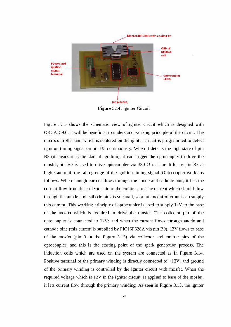
50
Figure 3.14: Igniter Circuit
Figure 3.15 shows the schematic view of igniter circuit which is designed with
ORCAD 9.0; it will be beneficial to understand working principle of the circuit. The
microcontroller unit which is soldered on the igniter circuit is programmed to detect
ignition timing signal on pin B5 continuously. When it detects the high state of pin
B5 (it means it is the start of ignition), it can trigger the optocoupler to drive the
mosfet, pin B0 is used to drive optocoupler via 330 Ω resistor. It keeps pin B5 at
high state until the falling edge of the ignition timing signal. Optocoupler works as
follows. When enough current flows through the anode and cathode pins, it lets the
current flow from the collector pin to the emitter pin. The current which should flow
through the anode and cathode pins is so small, so a microcontroller unit can supply
this current. This working principle of optocoupler is used to supply 12V to the base
of the mosfet which is required to drive the mosfet. The collector pin of the
optocoupler is connected to 12V; and when the current flows through anode and
cathode pins (this current is supplied by PIC16F628A via pin B0), 12V flows to base
of the mosfet (pin 3 in the Figure 3.15) via collector and emitter pins of the
optocoupler, and this is the starting point of the spark generation process. The
induction coils which are used on the system are connected as in Figure 3.14.
Positive terminal of the primary winding is directly connected to +12V; and ground
of the primary winding is controlled by the igniter circuit with mosfet. When the
required voltage which is 12V in the igniter circuit, is applied to base of the mosfet,
it lets current flow through the primary winding. As seen in Figure 3.15, the igniter

51
circuit has a connector to connect the GND terminal of the induction coil; the
connector is connected to the drain pin (pin 1 in Figure 3.15) of mosfet and when the
mosfet is triggered, it will let the current from drain pin to GND of the system [4].
This flowing current is relatively high so a cooling fin is assembled on the mosfet as
seen in Figure 3.15. And, the PCB layout of the igniter circuit is given in Figure 3.16.
(The figure is the bottom layer and board edge of the PCB and the PCB is one sided.)
Figure 3.15: Schematic view of igniter circuit
Figure 3.16: PCB layout of the igniter circuit

52
3.3 Control Circuits
As it is understood, the igniter circuits are slave circuits, they start ignition when an
ignition signal comes from the main circuit (ECU) as seen in Figure 3.13, Toyota 1
MZ-FE 94 Direct Ignition System (DIS). In our system, we have a PIC16F877A
based master circuit, to control the other slave circuits. The most important
component of the circuit is PIC16F877A, it is a high performance risc cpu by
Microchip [1], and it is very popular it means there are thousands of source codes
related to this microcontroller on the internet. The important specifications of the
mcu for our application are given below in Table 3.4.
Table 3.4: The features of PIC16F877A
Max
Operating
Frequency
Flash
Program
Memory
Data
Memory
(bytes)
EEPROM
Memory
(bytes)
Interrupts
I/O
Ports
Timers
Serial
Communication
10-
bit
ADC
20
MHz
4K 368 256 15 Ports
A, B,
C, D,
E
3 MSSP, USART 8
As seen in the Table 3.4, it can work at 20 MHz frequency it means 5000000
cycle/second (200 nanosecond instruction executions). Also it has five I/O ports,
serial communication modules and eight analog to digital conversion channels, these
features are enough for our application.
In our system, the rpm value and cooling temperature will be used as inputs to
determine advance angle and initiate ignition. These values will be read in analog
forms, so the main circuits should have connections for analog channels. The control
circuits will communicate with each other via master slave serial communication, so
the control circuits will have RX and TX connections. (RX and TX pins of
microcontrollers are used for serial communication) [26]. Also, those pins should be
connected to RS-232 port via max232, because we may need to communicate the
control circuits with PC to upload advance angle data. The igniter circuits will be
triggered by logic ignition timing signals of control circuits, so the control circuit

53
should also contain I/O pin connections and light emitting diodes to debug the source
codes which are written for control circuits. Engine control circuits have external
eeproms to store advance angle data, so the control circuits should have an external
eeprom memory. In the light of required features which are stated above the control
circuits are designed, there are two identical control circuits (they are designed
identically to reduce cost and time required for designing), but their duty, so their
source codes will be different (these control circuits will be called as main control
circuit and secondary control circuit according to their duty). Figure 3.17 shows
schematic view and Figure 3.18 shows PCB layout of the control circuits. As seen in
the Figure 3.17, there are three analog channels; these channels will be used to
measure analog rpm value and cooling water temperature. The circuit has max232
and serial communication port which may be used to communicate with PC; and has
RX and TX pin connections, these pins will be used to communicate the control
circuits with each other. The circuits have external eeprom memories which are used
to store advance angle data as look-up table. In our system, 24C64 series eeprom is
used to load look-up advance table, the 24C64 eeprom provides 65536 bits
electrically erasable and programmable read only memory, it means we can write 8
bit advance data to 8192(13 bit) addresses. Also, it supports I2C and SPI
communication protocols. Main circuit uses cooling water temperature and rpm
value as inputs to figure out the advance angle. The cooling water temperature is
measured via one of the analog input pins shown in Figure 3.17 and converted into
digital form by 10-bit analog to digital conversion module of the main control circuit.
The source code of main control circuits is written to read rpm value in 8-bit digital
format via serial communication, so there is a need for a circuit to measure rpm value
and format it into 8-bit form. Our secondary circuit is dedicated to measure rpm and
formats it into 8-bit form. The secondary control circuit sends rpm value to the main
circuit via serial communication with RX and TX pins, the mcu PIC16F877A has
Universal Synchronous Asynchronous Receiver Transmitter (USART) module which
is one of the two serial I/O modules. (USART is also known as a Serial
Communications Interface or SCI.) [26]. This module can be configured as a full-
duplex asynchronous system that can communicate with peripheral devices, such as
CRT terminals and personal computers or it can be configured as a half-duplex
synchronous system that can communicate with peripheral devices, such as A/D or

54
D/A integrated circuits, serial EPROMs, etc. In our system synchronous mode
communication is used, this is a one way communication because the secondary
circuit receives no data from the main circuit. When we look at the communication
mode, the main circuit is set as slave, the secondary circuit is set as master, and it
means secondary circuit transmits data, the main circuit receives that data, but this
communication starts whenever the main circuit sends a ready signal to the
secondary one.
Actually, the main circuit and the secondary circuit have the same hardware except
24C64 eeprom, because reading advance angle value from a look-up table is the duty
of the main control circuit(secondary control circuit also has connections for 24C64,
but it will not use the eeprom memory during operation). As seen in the Figure 3.18,
the external eeprom is connected to PIC16F877A with its SDA and SCL pins. SDA
is serial data I/O pin and SCL is serial clock input of the external eeprom [26]. Those
pins are connected to pin C4 which is used as serial data I/O and pin C3 which is
used as serial clock output of PIC16F877A. The connection which is given above
will be used to read data from external eeprom memory via I2C protocol of MSSP
module. The secondary control circuit will count the square wave output of position
sensors to determine crank shaft angle and receive ready signal from the main control
circuits, so the D0, D1 and D2 pins which is seen in figure 3.17 will be used for these
purposes. The control circuits have connection port for PORTB and light emitting
diodes connected to PORTB. The PORTB of main control circuit is used to send
ignition timing signals to igniter circuits. The leds connected to this port will be used
to simulate ignition timing signals and debug the source code.
The PCB layout of control circuits is given in Figure 3.18; these control circuits are
manufactured by ironing method (commonly used by amateurs to manufacture
circuit board). These circuits are also used to test control codes to check if they
succeeded, but for the final design more professionally assembled and manufactured
PCBs may be used. The PCB layout which is given in Figure 3.18 can be
manufactured by professionals or standard PIC16F877A development circuits can be
used. There is such a PIC16F877A development board (Altas yayincilik) in the
market as seen in figure 3.19. The development board has all the necessary pins,
connections, leds and external eeprom connection which we need in the control

55
circuits. To use this development board as control circuit will be beneficial because
this circuit is professionally assembled and tested.
Figure 3.17: Schematic view of the main control circuit

56
Figure 3.18: PCB layout of the main control circuit
Figure 3.19: Main control circuit

57
3.4 Speed Measurement and Cylinder Identification
3.4.1 Magnetic Pick-up
The rpm value is measured with a sensor which is a variable reluctance magnetic
pick up, Figure 3.20, it is a commercial product and it can be found easily as a spare
part in the market.
Figure 3.20: Magnetic pick-up which is used in our system
This sensor is widely used in automotive industry because of its enduring structure
and easy working principle. As seen in Figure 3.21, it is composed of a permanent
magnet, a pole piece metal and a coil, the working principle is if a metal piece closes
to the pole piece part it causes a change in the magnetic field and it induces a voltage
in the coil, this induced voltage is observed with the signal wires as a AC form [30].
Figure 3.21: Typical Magnetic Pick up

58
3.4.2 Frequency to Voltage Converter Circuit
As stated before, the output of magnetic pick-up sensor is a useless ac signal, so to
use the output you should shape it into square wave form or you should use
frequency to voltage converter to get an analog signal. There is an integrated circuit
in the market which is called LM2907, frequency to voltage converter; it is an 8-pins
small integrated circuit. This integrated circuit is widely used in the automotive
industry to get analog signal from the ac output of the magnetic pick up sensors.
Figure 3.22 shows an example circuit of frequency to analog signal converter [30],
this example circuit is the same with the circuit used in our application. After
converting the ac signal to analog signal, the secondary control circuit converts it
into 8-bit digital form by using A/D conversion module.
Figure 3.22: Basic Frequency to Voltage Converter.
Sensor, power, capacitor and resistor connections are shown in Figure 3.22, but the
output voltage will be different for different capacitor and resistor combinations in
the datasheet of LM2907 this situation is defined with an equation as follows [30].
Vout=Vcc x fin x C1 x R1 x K (K is the gain constant and typically 1)
Eqn. 3.1

59
In frequency to voltage converter design, the resistor, capacitor and supply voltage is
chosen to keep output voltage within 0-5V. So, according to Eqn. 3.1 circuit is
designed in ORCAD 9.0 as in figure 3.23. The maximum output voltage is calculated
around 4.8 V for 3000 rpm (4000 Hz for gear wheel with 80 teeth) in the design. This
designed frequency to voltage converter circuit is manufactured with the PCB layout
which is given in Figure 3.24 with ironing method.
Figure 3.23: Schematic view of frequency to voltage converter circuit
Figure 3.24: PCB layout of frequency to voltage converter circuit

60
3.4.3 Generation of Cylinder Position Signals
Another duty of the secondary control circuit is to send cylinder position signal to the
main circuit, to do this job there are 2 secondary LM2907 circuits, these circuits
converts the ac output signal of the magnetic pick up sensor to square wave, then the
secondary control circuit easily counts square waves to determine crank shaft angle.
There are two secondary LM2907 circuits which convert AC signals to square wave
in our system; one of them is used to determine crank shaft angle as stated above and
it is called secondary LM2907 circuit 1; the other one is used to detect first piston
position and it is called secondary LM2907 circuit 2. The application circuit of
LM2907 to convert AC signals to square wave [30] is shown in Figure 3.26.
Figure 3.25: Square wave signal generator circuit (secondary LM2907 circuit)
As it is understood from the Figure 3.25, the magnitude of square wave is dependent
on supply voltage. So the secondary LM2907 circuit is designed to have 0-5V square
wave as in Figure 3.26.

61
Figure 3.26: Secondary LM2907 circuit
Figure 3.27: PCB layout of the secondary LM2907 circuit
There is a gear wheel which triggers the magnetic pick-up sensor as you see in figure
3.28, this gear wheel is used to determine engine speed and piston positions, the gear
wheel which has eighty teeth to simulate an actual engine, and it means ten teeth per
cylinder. There is a metal part mounted on the gear wheel it is an additional tooth and
it is used to determine first piston position.

62
Figure 3.28: Gear wheel and driving system figure
The frequency to voltage converter circuit which is told in part 3.4.2 uses this gear
wheel and outputs of crank shaft position sensor in Figure 3.28 as input. As seen in
figure 3.28, gear wheel is driven with a belt and a motor, this motor is 0.36 kW AC
motor and it is driven by Delta VFD 004L11A series ac motor driver. It is very
useful for laboratory works because it has many parameters to change control
settings and gives the operator permission to change these settings. For example you
can control this driver with its digital keypad, its potentiometer, 0-10V input voltage,
4-20 mA input current or RS-485 communication port. Among these options to
control motor speed, 0-10V input voltage option is suitable for us because we have a
data acquisition card having analog output channels.
3.5 Data Acquisition and Control System
3.5.1 Data Acquisition Card and Its Accessories
One of the most important parts of the experimental set-up is data acquisition and
control system. It contains a computer, control software, Advantech PCI 1716 data
acquisition card, Advantech PLC-10168 wiring cable, PLCD-8710 wiring terminal
board and a transmitter/receiver circuit.
The computer in the experimental set-up is a standard personal computer, we don`t
need a special computer for this set-up, all we need is a computer which it can run
Delphi 4.0 software and has a PCI bus. The data acquisition card on the set-up is
Advantech PCI-1716 100kS/s, 12-bit, 16-ch Universal PCI Multifunction Card, it has

63
16 channels single-ended or 8 channels differential or a combination of analog input,
12-bit A/D converter with up to 100 kHz sampling rate, programmable gain,
automatic channel/gain scanning, onboard FIFO memory, 2 12-bit analog output
channels, 16 channels digital input and 16 channels digital output and onboard
programmable counter. These properties are acceptable for an experimental work.
The data acquisition card is a PCI type card, Figure 3.29, so we need special cable
with connector and a terminal board for I/O connections. PCL-10168 cable and
PCLD-8710 industrial wiring terminal board is used on the set-up, Figure 3.30.
These are accessories for this card supplied by Advantech.
. Figure 3.29: Advantech PCI-1716

64
Figure 3.30: Connection terminal box and connector cable
The data acquisition card 16 digital outputs and 16 digital outputs as stated before,
but to use these inputs and outputs in your experimental set-up you need another
circuit because digital outputs are not enough to drive inductive loads and you should
isolate digital inputs from bad signals, there is an interface circuit for this purpose.
The circuit has four 74LS245 IC`s, this IC is a octal bus transmitter/receiver, they are
used to isolate the data acquisition card from bad input signals. There are 16 relays
on the circuit, they are driven by ULN2003A high voltage, and high current
Darlington arrays each containing seven open collector Darlington pairs with
common emitters. These integrated circuits are triggered by output signals of the data
acquisition card, with these interface circuit our data acquisition system have 16
isolated digital inputs and 16 relay outputs which is capable of driving inductive
loads. Figure 3.31 shows interface circuit.

65
Figure 3.31: Interface circuit
Interface computer program which is necessary to control the hardware told above
was developed with Delphi 4.0, this interface program is used for different
experimental set-ups in the laboratory, so our program was added on the existing
program. Figure 3.32 shows opening view of the program.

66
Figure 3.32: Opening view of the interface program
As it is used various experimental set-ups, there is a option to choose data acquisition
card, our card is PCI-1716. The next step is choosing our experimental set-up; Figure
3.33 shows how we open our main page.
Figure 3.33: The next step to open our set-up page

67
Figure 3.34 shows how our main page looks like, we can control speed of the motor,
scan digital inputs and play animation of our ignition system via this interface.
Figure 3.34: Main page of our control software

68
CHAPTER 4
EXPERIMENTAL METHOD
In this part of the thesis, experimental method and how the elements of the set-up
which are told in previous chapter are used together will be stated. There are many
circuits and their working principle, schematic view and PCB layout are given in the
previous chapters, it will be helpful to review their working principles and duties in
the set-up. There are 3 LM2907 circuits, one of them is designed as a frequency to
voltage converter and the others are designed as square wave generator circuits.
There are 2 position sensors; they are crank shaft position sensor and reference point
sensor. The crank shaft sensor is connected to frequency to voltage converter
LM2907 circuit; the aim of this connection is to measure engine speed as voltage.
The crank shaft position sensor is also connected to one of the square wave generator
LM2907 circuits. This connection is used to create 0-5V pulse for each tooth of the
gear wheel in Figure 3.28. So, control circuits count the pulses and determine the
crank shaft angle and identify the cylinder positions. We should have a reference
point to start to count the pulses; this is held by reference point sensor and the other
of square wave generator LM2907 circuits. Control circuits detect the output of that
square wave generator circuit to start to count the pulses. The reference point is the
position of the first cylinder. Secondary control circuit is dedicated to measure the
speed by using output of the frequency to voltage converter circuit and send rpm
value in 8-bit format to the main control circuit and identify cylinder positions (by
detecting the reference point and counting the output pulses of square wave generator
circuit) and send them to the main control circuit. The duty of the main control
circuit is to detect the cylinder position signals (0-5V pulses) coming from the
secondary control circuit and add advance angle value to the cylinder position signals
and trigger the igniter circuits. The connections for all the circuits are given in Figure
4.6, and examining this figure will be beneficial for understanding the connections
and duties of the circuits.

69
4.1 New Design Engine
It will be helpful to state important points of the study and test engine. This ignition
system set-up is constructed for a special kind of engine, so the first step is to
understand the working principle of the engine. The engine has 8 cylinders arranged
radially on the engine, and there are 2 pistons for each cylinder it means there will be
ignition at respective sides of common cylinders. The engine has 2 special axial cams
at the each side of the engine. Another important point is ignition order of the spark
plugs, each side of the cylinder has ignition for each revolution of the engine unlike a
conventional four strokes one, because there is one ignition in a cylinder for every
two revolutions in a conventional 4-stroke cycle engine as in Figure 4.2. In other
words, crank shaft angle of the new design engine gives which piston is at which
stroke. Figure 4.1 shows parts of our new special engine.
Figure 4.1: Engine for which the ignition system set-up was constructed
Figure 4.2 shows four stroke cycle of a conventional internal combustion engine, as
shown in the figure it is impossible to determine the firing order with only crank
shaft angle (except wasted spark ignition). For example, the crank shaft angles of
compression stroke and exhaust stroke are the same in the figure. So to determine the
correct ignition order there will be need to another sensor output.

70
Our study is based on a special type of engine and its firing order is different but
physics of a combustion process is the same so the different part of our ignition
system is about firing order and its determination.
Figure 4.2: Four strokes of an internal combustion engine
4.2 Working Principle of the System
In this part of the thesis, the working principle of the system is going to be given.
The duties of the circuits and their relations with the other circuits are going to be
shown and told. The working principle is not going to be given operation by
operation, the operations are going to be grouped according to the circuits realizing
the operations, but it is going to be in an order. To follow the operations easily, it
will be helpful to look at Figure 4.3 the flowchart of the control algorithm of the
system.

71
Figure 4.3: The flowchart of the control algorithm of the system

72
The connection diagram in Figure 4.4 shows the exact connection of the circuits,
they are not symbolic connections. It will be helpful to understand the control
algorithm, operation order and the circuits in relation.
Figure 4.4: Connection diagram of the circuits
Figure 4.5 shows the operation order and the circuits realizing the operations. The
system should be examined operation by operation, the operations and their order can
be followed with Figure 4.5 and the algorithm of the operation can be seen in figure
4.3; and the wire connections for the operation can be seen in Figure 4.4, so the
Figure 4.3, 4.4 and 4.5 should be examined together.

73
Figure 4.5: The operation order and the circuits realizing the operations.
4.2.1 Speed Measurement and Piston Position Determination
4.2.1.1 Position Sensors
Figure 4.6 shows a four stroke four cylinders combustion engine and its front view;
there are a gear wheel with a missing tooth on the crank shaft and a pick-up coil type
sensor. These components are used to determine position of the crank shaft and
speed of the engine.
Figure 4.6: A Four cylinder demo engine and its front view

74
As stated before, the crank shaft position sensor is not enough to determine the
correct ignition order, so we need another sensor output; this sensor is camshaft
position sensor. Figure 4.7 shows typical outputs of crank shaft position sensor and
camshaft position sensor in a conventional crankshaft engine.
Figure 4.7: Typical outputs of position sensors
The periodic gap in the crankshaft position signal is because of the missing tooth in
the gear wheel. The gap is used by control unit as a reference of the crankshaft
position. When it is combined with the camshaft position signal, cylinder position
and stroke can be determined. In our case, a missing tooth in the gear wheel will be
enough to determine cylinder positions and strokes because the all strokes are
completed in one revolution of the engine by the help of two axial cams, so the same
operation is going to take place at the same crank angle in every revolution.
We have used an additional tooth instead of the missing tooth; the source code of
control circuits will be simpler by this way. Figure 3.28 shows gear wheel, additional
tooth and sensors. There are two sensors, crank shaft position sensor and reference
point sensor. Outputs of position sensors in our system are shown in Figure 4.8, as
you see in the figure there is no periodic gap in the crankshaft position sensor
because we do not have any missing tooth. This signal is used to determine engine
speed and crankshaft angle as told in the previous chapter.

75
Figure 4.8: Outputs of position sensors in our system.
4.2.1.2 Speed Measurement
There are many steps in ignition process and, they repeat in each revolution of the
engine. The first step is reading rpm (revolution per minute) and transferring it to the
main circuit in required format, the output of crank shaft position sensor is used to
read rpm value by using LM2907, frequency to voltage converter, based circuit as
mentioned in previous chapter. Figure 4.9 shows typical application circuit of
LM2907 to measure the engine speed. This circuit uses the crankshaft position sensor
output as input, and converts it into voltage shown in Figure 4.9 as Vout.
Figure 4.9: Typical application circuit of LM2907 to measure speed

76
The most important advantage of this circuit is that its output is in analog form, so
whenever you want to read rpm the only thing to do is analog to digital conversion,
you do not need to count any pulses or store any data to read speed. To determine
speed of engine you may use sensors with digital output and count the teeth of gear
wheel assembled on crankshaft, but you should count the teeth continuously it means
another extra circuit. The main control circuit manages every operation in the
system, so reading rpm voltage operation starts with ready signal of the main control
circuit, the main circuit makes the pin high, PORTD,1 it means the main control
circuit is ready for data transfer, after the secondary control circuit see the ready
signal , it reads analog rpm signal (output of LM2907 circuit) and converts it into
digital form, as given in the previous chapter the main and secondary control circuits
are both based on PIC16F877A microcontroller, and it has 10-bit analog to digital
conversion module, so analog to digital conversion of rpm signal gives two 8-bit
variables. The main control circuit needs rpm value in 8-bit format, so the secondary
control circuit makes required mathematical operations; they are 16-bit division and
subtraction, to scale two 8-bit variables into one 8-bit form. Then the secondary
control circuit sends 8-bit rpm data with USART synchronous master/slave
communication with 500 kHz baud rate.
The main control circuit manages every operation in the system but during the serial
communication it acts like slave because it just receives data. The serial
communication takes place with the TX and RX connection as seen in Figure 4.3.
The Figure 4.10 shows the operational view of the engine speed measurement

77
Figure 4.10: Operational view of the engine speed measurement
4.2.2 Piston Identification and Crankshaft Angle Measurement
The output of position sensors are low level analog signals, we shape it into square
wave form to use them as a trigger signal in our microcontroller based secondary
circuit. This job is done by secondary LM2907 circuits; this application of LM2907
is shown in Figure 4.11. There are two identical circuits in the system, one is for
reference point sensor output, and another is crankshaft position sensor output which
is also used to determine engine speed as seen in Figure 4.4.
Figure 4.11: Secondary LM2907 circuit

78
The outputs of secondary LM2907 circuits are square form of the ac analog signals
as seen in Figure 4.11. After the secondary control circuit sends the engine speed
data to the main circuit in 8-bit format, it goes to the second step. This step is to find
the reference point of the crankshaft and crankshaft angle, it starts with the reference
point detection, because firing of spark plugs start with a reference point and
continues sequentially. As stated before, reference point is our additional tooth and it
is detected with reference point sensor. The pin PORTD,1 of the secondary control
circuit is dedicated to detect reference point signal, when it receives the signal, the
secondary control circuit makes PORTB,7 high for 20 µs this is first cylinder
position signal; Pin PORTB,7 is connected to pin PORTD,0 of the main control
circuit, as seen in figure 4.3 and it is triggered at the falling edge of cylinder position
signal. Then secondary control circuit starts to count square waves of crankshaft
position signal, PORTD,2 of the secondary circuit is dedicated for this purpose, if it
counts ten pulses, ten pulses mean 45 º rotation of crankshaft because the gear wheel
has 80 teeth for 8 cylinders, it makes high PORTB,7 for 20 µs this is position of
second cylinder, the secondary circuit repeats this process for seven times, then it
goes to the initial point and wait ready signal from the main circuit for the next
revolution. As it is told above, the main circuit communicates only with the
secondary circuit for engine speed and piston identification.
Main control circuit uses cylinder position signals to create ignition timing signals.
The gear wheel will be mounted on the engine as rotated 22.5˚, it means the cylinder
position signal gives the middle point of two cylinder. And the advance value will be
added on this point to find the required position of the ignition. Figure 4.12 shows
the operational view of the piston identification and crank angle measurement.

79
Figure 4.12: Operational view of the piston identification and crank angle
measurement
4.2.3 Receiving Speed Data and Reading Cooling Water Temperature
There are many factors such as engine load, speed, temperature, richness of air-fuel
mixture etc. which affect the combustion process in the cylinder. Ignition system
shall be designed to adapt itself to changes in these variables; our ignition system set-
up is designed to use engine speed and temperature to arrange ignition point. There
are many parameters which can be used as input to arrange ignition point such as
pressure of the inlet manifold or exhaust gas temperature, but for the time being
engine speed and cooling water temperature is enough to develop ignition control
system for the laboratory.
The first thing which the main control circuit does after initialization is sending ready
signal to the secondary circuit with its pin PORTD,1 and waiting for data transfer, if
there is a problem in the secondary circuit or data transfer wiring, the main circuit
will keep waiting for data transfer, but a timer can be used to limit waiting time for
the data transfer and if there is not data transfer during that time, previously
transferred data can be used. After receiving engine speed data, it reads cooling water
temperature sensor output and it converts it into digital form by using analog to
digital conversion module, this module has 10-bit resolution and our system uses

80
cooling water temperature in calculations as 5-bit format, so the main circuit makes
necessary 16-bit calculations to scale digital cooling water temperature data into 5-
bit.
4.2.4 Selection of Advance Angle and Ignition Timing Signals
The main duty of the main circuit is to determine the ignition timing and send the
ignition timing signals to the slave igniter circuits. The main control circuits receive
cylinder position signals at pin PORTD,0 from the secondary control circuit. In our
system, cylinder position signal shows the middle point of the two cylinders; this is
our reference point to calculate ignition point. The ignition timing signals are
advance angle added form of the cylinder position signals. Figure 4.13 shows the
physical meaning of the advance angle value, the advance angle value is the required
time to travel from the cylinder position to the ignition point. There are 16 ignition
points in our new design engine, but the two ignitions take place at the same time, so
we need 8 position signals as seen in Figure 4.13. The two ignitions taking place at
the same time are generated by the induction coils with two high voltage output, so 8
igniter circuits and 8 induction coils are used in the system.
Figure 4.13: Advance angle value

81
Ignition advance is the number of degrees before or after top-dead-centre (TDC) that
a spark occurs in conventional crank shaft engines. The reason for ignition advance
is that the spark needs to be timed so that the point of peak combustion pressure is
when the piston is just beyond TDC.
If the point of peak combustion pressure is too early and before TDC the pressure
wave will slow down the speed of the piston traveling up towards it, and may cause
detonation (knocking) which is very damaging to the engine. If the point of peak
combustion pressure is too late, the pressure wave will chase the piston as it travels
back down the cylinder in the combustion stroke and most of the energy will be lost.
This advance angle changes during the engine operation due to engine load, engine
speed, fuel, temperature etc., for example as the speed of the engine rises, the
ignition advance angle needs to increase. The philosophy behind this: because the
time to burn an unchanging air/fuel mixture is approximately constant. If the ignition
advance angle were kept the same, the point of peak combustion pressure would
move further and further into the combustion stroke losing more and more power.
Therefore the ignition advance needs to be increased to bring the point of peak
combustion to just beyond TDC. The ignition advance decreases while engine load
increases, because the amount of time taken for a fuel/air mixture to burn mainly
depends on the richness of the fuel mixture. When the engine is under low load with
a lean air/fuel mixture the degree of ignition advance will need to be large to allow
for the slow combustion of this mixture. Conversely when the engine is under load a
richer air/fuel mixture is used to provide more power. This richer mixture has a faster
combustion time so the degree of ignition advance needs to be reduced to keep the
peak combustion pressure just beyond TDC, the temperature also do the same effect
with the engine load. Those possible problems are valid for conventional crank shaft
engines, because the combustion process in the new design engine takes place in
constant volume, one of its advantageous sides, and the advance angle should be
calculated to find the ignition point in the constant volume area. But, the parameters
which affect the advance angle will also affect the advance angle of the new design
engine.
As it is stated above, the ignition advance angle is dependent on a few variables;
during the operation it is impossible to calculate advance angles due to these
variables. So in modern engines look-up tables are used to select suitable advance

82
angle for specific engine operation conditions. These look-up tables contain
experimental advance data and they are loaded to eeprom memories. Figure 4.14
shows advance angle map which is dependent of engine load and engine speed.
Figure 4.14: Advance angle map
In our system, 24C64 series eeprom is used to load look-up advance table, the 24C64
eeprom provides 65536 bits electrically erasable and programmable read only
memory, it means we can write 8 bit advance data to 8192(13 bit) addresses, 13-bit
address is divided as 8 bit + 5 bit in our application according to importance on
advance. As seen in figure 4.15, the main circuit uses rpm value and cooling water
temperature as eeprom address to select suitable advance angle from the look-up
table, rpm value is the 8-bit address part (ADDRESSL) and cooling water
temperature is the 5-bit address part (ADDRESSH) [26].

83
Figure 4.15: Operational View of the Main Circuit
(The values 3.275 V and 10101 01011101 are symbolic numbers). The required
advance angle value for the engine speed and cooling water temperature in the
address which the advance angle value will be read from, was loaded into that
address before, this is the philosophy to load advance angle map into eeproms.
Selection of advance angle according to engine speed and cooling water temperature
is told above, the advance angle value which is read from the eeprom is a time delay
and this delay is added to cylinder position signal. The main control circuit program
goes to wait for position signal of the first cylinder after it reads the advance angle
value. When it detects the falling edge of the first cylinder position signal it waits for
a moment, this moment is advance angle value which is read from eeprom memory,
and then it sends ignition point (the falling edge of the ignition timing signal) to the
first igniter circuit, and it repeats this process for eight times.

84
Figure 4.16: Ignition timing signals
The ignition timing signal is a square wave, when the main control circuit receives
the cylinder position signal it makes its related pin high (ignition mode_0), after
advance delay it makes the pin low and creates the spark with the igniter circuit. The
point at which the pin is made high changed according to the engine speed, it is
called dwell angle and it is going to be told in part 5.5.
For the time being, it is impossible to determine advance values, because advance
angle values are determined after series of tests which is called calibration tests.
4.2.5 Receiving Ignition Timing Signal and Firing Spark Plugs
As stated in previous chapter, there are eight PIC16F628A based igniter circuits
which are dedicated to receiving ignition timing signals and trigger induction coils.
Ignition timing is determined by the main circuit according to advance angle, as seen
in Figure 4.16, it is a square wave. In signals which are in square wave form, there
are two reference points, rising edge and falling edge. Our igniter circuit detects its
related input pin continuously to catch the rising edge of ignition timing signal, when
it catches the rising edge it opens the way of current which flows through the primary
winding of induction coil by driving mosfet via optocoupler. Then it starts to detect
the related input pin continuously to catch the falling edge of ignition timing signal,
when it detects the falling edge, it closes the way of the current suddenly to induct
high voltage in the secondary winding of induction coil.
This high voltage jumps to ground via spark plug as a spark and ignition occurs.
Figure 4.17 shows operational view of the igniter circuit.

85
Figure 4.17: Operational view of the igniter circuit

86
CHAPTER 5
DESIGN CALCULATIONS
Control circuits which are used in our system are based on PIC microcontroller and
the microcontroller units on the circuits are programmed in assembly language.
Ignition is a fast process, so our ignition system should be fast enough to initiate
ignition at the required time. In the circuits 4 MHz crystals are used as an oscillator;
it means our circuits are able to make 1000000 operations per second; this
operational speed is suitable for our application, but the control circuits convert
analog speed signal and cooling water temperature to digital value, and read ignition
advance angle value from an external eeprom these are time consuming operations,
so the registers related to operational speed of these operations should be set
according to time requirements.
5.1 A/D Conversion Calculations
5.1.1 Acquisition Time
Before the analog to digital conversion starts, the charge holding capacitor (CHOLD)
must be allowed to fully charge to input channel voltage level. Analog input model
of PIC microcontroller unit is given in Figure 5.1; according to analog input model
the source impedance (RS), internal sampling switch impedance (RSS) and
interconnect resistance (RIC) directly affect the time required to charge the capacitor
(CHOLD).

87
Figure 5.1: Analog input model
Another parameter affecting acquisition time is amplifier settling time, internal
amplifier of the microcontroller unit is set before the conversion. Also working
conditions especially temperature affects acquisition time of the microcontroller unit.
The acquisition time of mcu can be stated as follows [1]:
TACQ = Amplifier Settling Time + Hold Capacitor Charging Time + Temperature
Coefficient (5.1)
= TAMP + TC + TCOFF
= 2 µs + TC + [(Temperature -25 ºC)*(0.05 µs/ ºC)]
TC = CHOLD *(R IC + RSS + RS)* ln(1/2047)
= -120 pF (1 kΩ + 7 kΩ +10 kΩ) ln(0.0004885)
= 16.47 µs
TAMP = 2 µs
TACQ = 16.47 + 2 + (75-25)*0.05
= 20.97 µs
The result of equation 4.1 gives the acquisition time of voltage, it may be assumed as
a delay before the A/D conversion. The order of magnitude of acquisition time is
microsecond; it is acceptable for our application.
5.1.2 Selecting the A/D Conversion Clock
The analog to digital conversion time per bit is defined as TAD. The analog to digital
conversion requires a minimum 12 TAD per 10-bit conversion process. For correct
A/D conversion operation, the A/D clock must be selected to ensure a minimum TAD
1.6 µs [1]. The source of the analog to digital conversion clock is software selected
and there are six options for TAD:

88
• 2 TOSC
• 4 TOSC
• 8 TOSC
• 16 TOSC
• 32 TOSC
• 64 TOSC
Note: TOSC is period of oscillator. The oscillator on the control circuits is 4 MHz
crystal:
Frequency (f) = 1/ Period (T)
5.2
4 MHz = 4000 000 Hz
4000000 =1/TOSC
TOSC = 0.25 µs
As stated before, TAD should be selected as minimum 1.6 µs.
X*T OSC = 1.6 µs X*0.25 µs = 1.6 µs so X = 6.4 (minimum)
So it is selected as 8TOSC. Conversion time can be calculated as 12*TAD
12*1.6 = 19.2 µs required time for 10-bit conversion.
5.1.3 A/D Conversion Resolution
As it is stated before, PIC16F877A has 10-bits A/D conversion module it means it
can sense 4.8876x10⁻³ volts.
Resolution = (Vref+ - Vref-) / (210-1)
5.3
= (5-0) / 1023
=4.8876x10⁻³ volts
5.2 Serial Communication Rate
In our system synchronous serial communication method is used. Minimum
operating time is selected for analog to digital conversion operation, but it is about 20
µs. There is no specific limit for serial communication rate, but it can be select as

89
equal to the analog to digital conversion rate. The required time for serial
communication will be selected as 16 µs (for 8-bit). Operational speed of serial
communication is defined with baud rate; it is numbers of bits transferred per second;
and it is set by SPBRG register. For synchronous serial communication [1]:
Baud rate = FOSC / (4*(SPBRG+1))
5.4
1/Baud rate = T (time required to send 1 bit data) (s)
5.5
As mentioned above, the required time for serial communication may be selected as
16 µs
So from the equation 5.5:
16x10^-6 = 8*(1 / Baud rate) for 8-bit data
Baud rate = 500 kHz
From the equation 5.4:
500000 = 4000000 / (4*(SPBRG+1))
SPBRG = 1
5.3 Reading Ignition Advance From External Eeprom
The most time consuming operation is reading ignition advance angle value from an
external eeprom. This operation is held by using I2C master mode operation. The
master device generates all of the serial clock pulses and the start and stop
conditions. The operation has two part as follows master transmitter mode and
master receive mode. In master transmitter mode serial data is output through SDA
pin (pin RC4) while SCL (pin RC3) outputs the serial clock. The first byte
transmitted contains the slave address of the receiving device (7bit) and read/write
(R/W) bit for this operation R/W bit will be logic 0; it means master device will
write. After each byte is transmitted an acknowledge bit (ACK) is received. In master
receive mode, the first byte transmitted contains the slave address of the transmitting
device (7 bits) and the R/W bit, for this operation the R/W bit will be logic high “1”.
Serial data is transmitted 8 bits at a time. After each byte is transmitted, an
acknowledge bit (ACK) is received the assembly code to check ACK bit is command

90
lines between 884 and 895 in Appendix A. The assembly code of the operations to
read data from external eeprom is between command lines 828 and 937 in Appendix
A. The external eeprom memory which is used in our system has 64 Kbit memories;
so it is addressed with 2 bytes; they are called high byte and low byte. The data
transfer rate of this communication is set with SSPADD register as below [1]
Clock = FOSC / (4*(SSPADD+1))
5.6
The original communication speed was defined with a maximum 100 kbit per second
(max frequency 100 KHz) so we will select clock as 100 KHz.
From the equation 5.6:
100000 = 4000000 / (4*(SSPADD+1))
SSPADD = 9
Equation 5.5 can be used to calculate required time to read or send 1-bit data as
follows:
1/100000 = 10 µs required time to send 1-bit data.
The operational view of reading 8-bit data from external eeprom with 2 byte address
is shown in Figure 5.2.
Figure 5.2: Operational view of reading 8-bits data in I2C master mode
The operations to read ignition advance angle value in our system will be as follows:
• Send 8-bit control byte
• Wait for ACK signal
• Send high byte of address which will be read
• Wait for ACK signal
• Send low byte of address which will be read

91
• Wait for ACK signal
• Send 8-bit control byte
• Wait for ACK signal
• Read 8-bit data
As stated above, to read 8-bit data the system send or receives 8 bit data for five
times and wait for ACK signal for four times. So required time to read 8-bit data will
be:
5*8*10 µs + 4 wait for ACK signal
400 µs + 4 wait for ACK signal
The operations and their time consumption were given above, but there are also
mathematical calculations and delays during the operation. And the time consumed
during those operations related to the engine speed so this time will be determined
experimentally. The important point here is the time consumed during those
operations shall not exceed time interval between two ignitions. This time interval
can be calculated as follows:
Time interval between two ignitions = (1000*60)/(8*Engine Speed) 5.7
5.4 Calculating Advance Delay
In our system, advance angle values are kept in external eeprom. The control circuits
read analog value and convert it into digital form. After the conversion, they scale it
into 5-bits or 8-bits form to form external eeprom addresses. In our system, the
cooling water temperature was taken as zero and advance angle addresses were
calculated. So, engine speed is the only criterion to read advance angle. After
conversion of engine speed into digital form, the related control circuit divides it to 4
to scale it into 8-bits form. It is calculated as in equation 5.8:
Eeprom address = Engine speed (volts) / [4*4.8876x10-3 (volts)] 5.8
Advance angles are determined after calibration of the engine, so at this time we do
not have data to write to the eeprom addresses. So, the advance angle values were
selected the same with eeprom addresses because we are just testing ignition system
for the time being. Advance delay which is read from external eeprom can be
calculated as in equation 5.9.

92
Advance delay = [Engine speed (volts) / [4*4.8876x10-3 (volts)]]*11 µs 5.9
5.5 Determination of Ignition Modes
As stated before, the ignition process starts with the flowing of the current through
the primary coil of the ignition coil. When the current is broken, the spark is
generated. But to have suitable spark quality, the ignition coils should be saturated,
so there is a minimum duration which the current should keep flowing. This duration
was observed around 5 ms for our ignition system. With the increasing engine speed,
the starting point of the ignition process should be advanced; this is called as dwell
angle. The main control circuit which manages the all operations is capable of
arranging the dwell angle with its code. There are 4 main modes which are mode_0,
mode_1, mode_2 and mode_3. Also, there are 3 transition modes between the main
modes; they are premode_1, premode_2 and premode_3. The ignition modes are
determined with the codes between 68 and 736 in Appendix A.
We have 2 points which we can use to arrange dwell angle they are cylinder position
signals and ignition points. We can start the ignition process when the cylinder
position signal is received (mode_0) which is valid for low engine speeds. We can
start the ignition process at the ignition point or cylinder position signals of the
previous cylinders. In mode_1, the ignition process is started at the ignition point of
the previous cylinder, in mode_2 the process is started at the cylinder position signal
of the previous cylinder and in mode_3 the process is started at the ignition process
of two cylinders before. And the premodes are used for the transition between two
ignition modes. The ignition mode intervals can be calculated as below.
Sweep Time (ms) = [Crank Angle (degree)] x 60000 / [360 x Engine Speed (rpm)]
5.10
The cylinder position signals give the position of the point which is around 22.5˚
before the cylinder, and the angle between the actual cylinder position and the
ignition point of the previous cylinder can be assumed as 45˚. The equation 5.10 can
be used to determine the starting point of the ignition process. The most important
parameter is that minimum sweep time between the starting point of the ignition
process and the spark generation is 5 ms, and we can use the points at 22.5˚, 45˚,
67.5˚, 90˚ etc.

93
Sweep Time (ms) = [Crank Angle (degree)] x 60000 / [360 x Engine Speed (rpm)]
5.10
We can arrange the equation 5.10 as follows.
Engine Speed (rpm) = [Crank Angle (degree)] x 60000 / [360 x Sweep Time (ms)]
Let`s calculate the maximum engine speed for 22.5˚ as a sample calculation:
Engine Speed = (22.5 x 60000) / (360 x 5)
Engine Speed (max) = 750 rpm this is the upper limit of the mode_0
For the sweep time 5 ms and crank angles 22.5, 45, 67.5 and 90˚, the engine speeds
calculated as follows.
Table 5.1 Maximum engine speeds of the ignition modes
Ignition Mode Crank Angle Max. Engine Speed (rpm)
Mode_0 22.5˚ 750
Mode_1 45˚ 1500
Mode_2 67.5˚ 2250
Mode_3 90˚ 3000
To stay in the safe region, the engine speed limits for the ignition modes are selected
as 650, 1350, 2050 and 3000. And the limits for the transition are selected as 700,
1400 and 2100. The usage of the speed limits is given in source code of the main
control circuit with the lines 68 and 115 in Appendix A. And the decimal number
which are used to determine the ignition mode (lines 74, 80, 86, 92, 98, 104 and 110)
are the rounded digital values of the lower limits of the ignition modes, and they are
calculated as follows.
Engine Speed (digital) = Engine Speed (rpm) x 4.8 / (3000 x Resolution) 5.11
As it is stated in previous chapters, the frequency to voltage converter circuit is
designed to have 4.8 volts output for engine speed and “Resolution” is the resolution
of the ADC module which is calculated with the equation 5.3

94
CHAPTER 6
SOURCE CODES OF THE CONTROL CIRCUITS AND IGNITER
CIRCUITS
As it was given in chapter 3, there are two control circuits and eight igniter circuits in
our experimental set-up; and those circuits are microcontroller based circuits. In this
chapter, the codes which were written and loaded to microcontrollers on the circuits
will be stated and explained. The source codes of microcontrollers were written in
assembly language and complied with MPLAB IDE v7.00 by Microchip. The
assembly language is more complex language than C or Basic based microcontroller
programming languages.
6.1 Source Code of the Main Control Circuit
In this part of the chapter, the source code of the main control circuit which is given
in Appendix A will be explained. The duty of the main control circuit is to manage
the operations, receive the rpm value from the secondary circuit, read the cooling
water temperature and scale it into 5-bit form, combine the rpm value with the
cooling water temperature to form the address of the external eeprom, read the
advance value from the external eeprom and arrange the ignition points. The main
control circuit is PIC16F877A based and it is working with 4 MHz crystal. As stated
before, PIC16F877A has 40 pins; and these pins have jobs more than one. For
example, a pin can be configured as analog input, digital input or digital output. So,
first thing which should be done during programming is to configure the pins of
microcontroller. The main body of the source code is labeled as main, the command
lines 10 and 11 calls the subroutines which configure the microcontroller to do the
jobs which are stated above. The command line 10 calls the subroutine which
initializes the I2C communication, serial communication, input-output pins and

95
analog channels. The duty of the subroutine “initialize” is as follows. As it is given in
chapter 4, the main control circuit uses its PORTD to receive cylinder position
signals from the secondary control circuit and send ready signal to the secondary
control circuit. The 0th pin of PORTD is used to receive cylinder position signals, so
it should be configured as input; and the 1st pin of PORTD is used to send ready
signal, so it should be configured as output. The command lines between 744 and
748 in initialize subroutine are used to configure PORTD. After sending ready
signal, the main circuit starts to wait for serial rpm value with synchronize serial
communication. In the experimental set-up, main control circuit works as slave and
the secondary control circuit work as master. The serial communication settings are
arranged with the command lines which are given below:
---- ---- ---- ---- ----
---- ---- ---- ----
There are some registers to configure serial communication mode and settings. One
of them is TXSTA. This register is used to select synchronous or asynchronous and
master or slave serial communication. The command line 765 is used to select
synchronous serial communication and command line 769 is used to select slave
mode serial communication. Another register is RCSTA, this is used to select 8-bit or
9-bit data transfer and open or close serial port. The command line 767 is used to
open the serial port and the line 772 is used to select 8-bit data transfer. After
receiving serial rpm data, the main control circuit reads analog cooling water
temperature and converts it into digital form. So the analog to digital conversion
parameters should be arranged. The command lines which are given below are used
to configure ADC.

96
---- ---- ---- ----
---- ---- ---- ----
The related registers to configure ADC settings are ADCON0 and ADCON1. The
value 0x41 is appointed to ADCON0 to set the ADC clock frequency Fosc/8 [1] with
command line 760 and 761. PIC16F877A has 10-bit ADC module, the format of the
10-bit data can be arranged by ADFM (bit-7) of ADCON1. In the source code, the
ADCON1 is arranged to have 000000xx (high byte of 10-bit data) and xxxxxxxx
(low byte of 10-bit data) with the command lines 762 and 764.
The main control circuit reads advance angle value from an external eeprom with
I2C protocol as it is given in part 5.3. From the result of equation 5.6 to have 100
kHz data transfer speed SSPADD register shall be 9. And to use I2C master mode
and SDA and SCL pins for data transfer SSPCON register shall be equal to
b'00101000'. All these requirements are arranged the codes in subroutine “I2C_init”
which is the subroutine of “initialize” as below:
---- ---- ---- ----

97
---- ---- ---- ----
After initializing the ports and communication settings, the first duty of the main
control circuit is send ready signal to the secondary control circuit by making high 1st
pin of the PORTD with command line 12 in source codes, this is the starting point of
the main loop which is called “loop”. Then it calls the “snkSlaveRead“subroutine.
This subroutine is used to read serial rpm data which is coming from secondary
control circuit by master-slave serial communication. The command lines of the
subroutine are:
---- ---- ---- ----

98
---- ---- ---- ----
The command line 815 is used to open the serial communication port and command
line 817 is used to configure slave communication mode. If there is an error during
the serial communication, CREN bit of the RCSTA register will be zero so it should
be set as high (1) before the communication, command line 819 is used for this
purpose. The RCIF bit of the register PIR1 will be high (1) when the serial
communication is completed. With the command line 820, the end of serial
communication is waited. The line 822 gets the received data to temporary variable
(W); and the command line 824 checks whether there is a communication error or
not. If there is an error, the program sets the 0th bit of konrol_register (it is a register
defined by the user). Then the user can check the kontrol_register and avoid
receiving wrong data. With the “return” command program returns line 18 and
appoint the value of “W” to tempH this is the first 8-bit of advance angle address.
The next step is to read cooling water temperature with analog to digital conversion
module. For this purpose there are two variables defined ADC_Oku_kanalno (line
22) and ADC_Oku_sonucbyte (line 24). ADC_Oku_kanalno is the number of analog
channel. As stated before, the PIC16F877A has 10-bit ADC module, so the result of
the conversion is two 8-bit data. They are the ADRESL and ADRESH; the low 8-bit
of the conversion is ADRESL and high 8-bit of the conversion is ADRESH. The
source code was written to read ADRESL firstly and read ADRESH secondly. To
read ADRESL, the value 0x00 is loaded to ADC_Oku_sonucbyte(line 24) and the

99
subroutine “ADC_Oku” is called. The subroutine “ADC_Oku” is between 783 and
801. The analog channel is chosen with the bit 5, 4 and 3 of the register ADCON0,
so ADC_Oku_kanalno value should be required 3-bit format, this is done with the
command lines 784,785 and 786. To initialize ADC module 0x41 values was loaded
to ADCON0 with command line 761, so this value should be added to 3-bit channel
number; this is done with command line 787.
---- ---- ---- ----
The analog channel is chosen with the bit 5, 4 and 3 of the register ADCON0, so
ADC_Oku_kanalno value should be required 3-bit format, this is done with the
command lines 784,785 and 786. To initialize ADC module 0x41 values was loaded
to ADCON0 with command line 761, so this value should be added to 3-bit channel
number; this is done with command line 787.

100
---- ---- ---- ----
The conversion starts with the command line 790, bsf ADCON0; 2. If the
ADC_Oku_kanalno is 0x00, program goes to “ADC_j1” and takes the low 8-bit of
the conversion and loads it into sicaklikL (command line 28); if the
ADC_Oku_kanalno is 0x01, program goes to “ADC_j2” and takes the high 8-bit of
the conversion and loads it into sicaklikH (command line 40). As stated in previous
chapters, the cooling water temperature will be scaled into 5-bit format. The
command lines between 43 and 58 which is subroutine “dongu2” scale it into 5-bit
format.
---- ---- ---- ----
---- ---- ---- ----

101
Now the program is ready to form 13-bit address of the external eeprom and read
advance value. In this study, the cooling water temperature was read for future works
but was not used as an input in this study, so the high byte of the external eeprom is
taken as zero with the line 62. The codes which are given below are used to form 13-
bit eeprom address and call the subroutine which reads the advance value.
---- ---- ---- ----
---- ---- ---- ----
With the command lines 59 and 60, the serial rpm value which is in 8-bit format is
loaded to “sayacH” then it is loaded to low value part of the eeprom address with the
command lines 63 and 64. For the time being there is no cooling water so the high
value part of the eeprom address is taken as zero with the command line 62. Now we
are ready to read advance angle value with the command line 65, “call
I2C_ReadEE”.
As it is stated in part 5.3 with figure 5.2, first of all we should start the I2C serial
communication this is done with subroutine “I2CStart” (command line 841). In this
subroutine, the start bit (SEN) of the register SSPCON2 is enabled by the command

102
line 844). Then the program waits for the being disabled of SEN bit of the register
SSPCON2 in subroutine “I2CStart_j1” to continue. Then it checks whether the
initiated start condition was completed by the MSSP module, by checking SSPIF bit
of the register PIR1 with command line 850. SSPIF bit will be high if the start
condition is completed. If it is enabled, the program erase that flag with bcf
PIR1,SSPIF command for the other operations. To learn the duties of the registers
and their bits, it will be helpful to look at the datasheet of PIC16F877A. The codes
required to start I2C communication are as below:
---- ---- ----- ----
---- ---- ----- ----
Now we can send the control byte to the external epprom, the control byte is
combination of hardware address of the eeprom (1010, MSB) and logic states of A0,
A1 and A2 pins of the eeprom and R/W bit (LSB), R/W bit is used to select reading
from eeprom or writing to the eeprom. R/W is 0 for wirting operation and 1 for
reading operation. A0, A1 and A2 pins are used to address the eeproms and give us
chance to use 8 eeproms at the same time (2^3=8, it means possibility of 8 different
addresses). All the pins in our application are connected to the GND. So, the 4 less
significant bits of the control byte is 0000. With the command lines 912, 913 and
914 the source code forms the control byte, by this method you can connect another
eeprom to the circuit and use it without changing the source code. With the command
line 915, the control byte is loaded to “I2CSend_data”.

103
---- ---- ---- ----
---- ---- ---- -----
Then the program goes to the subroutine “I2CSend”, this is the subroutine which
sends the data to the external eeprom with the code given below. There is an another
register called as “SSPBUF”, this is the buffer of the master synchronous serial port;
so to send the data I2CSend_Data is loaded into that register with the command line
863.
---- ---- ---- ----
---- ---- ---- ----
The other subroutine in the routine “I2C_ReadEE” is “I2CAck“, as it is seen in
figure 5.2, after data transfer external eeprom send a received signal. (Ack means
acknowledged). The most important line of that routine is “btfsc SSPCON2,
ACKSTAT” because ACKSTAT bit of the SSPCON2 becomes low (0) when the
data is received by the eeprom. The duty of I2CAck subroutine is to check whether
the data sent to the eeprom is received or not.
After the control byte, the high byte part of the eeprom address is sent to eeprom, for
each data transfer the I2CACK subroutine is called to check whether the data is sent
or received. The codes below are used to send the high byte of the address and
checkACK.

104
---- ---- ---- ----
---- ---- ---- ----
Then the low byte part of the eeprom address is sent to the eeprom and ACK is
checked again.
---- ---- ---- ----
---- ---- ---- ----
The next step needs to be paid attention, the address value is sent to the eeprom and
the data at that address will be read, to read a value from the external eeprom, new
control byte with R/W=1 should be sent, so the eeprom should be restart again. To
restart the eeprom the subroutine “I2CReStart” will be called, to restart the eeprom
RSEN bit of SSPCON2 register will be set with the command “bsf SSPCON2,
RSEN“(command line 857). Then control byte should be sent to the eeprom, but
R/W bit shall be 1, it means reading operation will be held. The codes which are used
to restart are given below.
---- ---- ---- ----

105
Finally the I2CRead subroutine will be executed. The value of the SSPBUF register
is the value of the data which we want to read. “I2CRead” subroutine has also some
registers and bits which are enabled or disabled after data transfer, these registers can
be easily found in the datasheet of PIC16F877A [1].
---- ---- ---- ----
The last step of reading advance angle data from an external eeprom is calling
I2CNak subroutine. This routine is used to check whether reading operation
completed or not, there are some registers which set or reset at the end of reading
operation these registers can be easily found in the datasheet of the PIC16F877A[1].
The codes which are given below are used to check “NO ACK”.

106
---- ---- ---- ----
---- ---- ---- ----
When the advance angle value is read from the external eeprom, the main control
circuit makes 1st bit of PORTD low by the command line 66. The read advance angle
value is loaded to variable “avans” with command 67. Now the circuit is ready to
receive cylinder position signals from the secondary control circuit and add advance
value to the cylinder position and ignite the spark plugs. As stated in previous parts,
to ignite the spark plugs we should saturate the ignition coils it means we let the
current flow through the primary coil of ignition coils for a while, this duration is
around 5 ms for our application. But, if the engine speed increases the time between
two cylinder positions decreases, so we do not have required time to saturate the
ignition coils and get poor spark quality. To avoid getting poor spark quality with the
increasing engine speed, the code block which is between command lines 69 and 115
was written. With this code block, the start point of the current flow through the
primary coil of ignition coils is advanced. With the commands between 68 and 72,

107
the rpm value is loaded to a variable “mode_sayac” and according to this variable
starting point of the current flow is determined.
For example, if the rpm value (mode_sayac) is between 1 and 54, it means the engine
speed is between 0 and 650 rpm, the subroutine mode_0 (command lines between
116 and 196) is called, with this subroutine main circuit receives first cylinder
position signal from the secondary control circuit with PORTD,0 and starts the
current flow through the primary coil of first ignition coil and then breaks the current
at the ignition point and spark occurs. And it repeats this sequence for the other
seven ignition coils. Then it goes to the starting point of the main loop (“loop”). For
this case, the engine speed is low and the time between two ignition points is much
enough to saturate the ignition coils. The “loop 7” which is given below is used to
check whether the engine speed is between 0 and 650 rpm
---- ---- ---- ----
---- ---- ---- ---- For the case mode_1 (command lines between 279 and 368), there is not enough time
between two ignition points, so the starting point of the current flow through the
primary winding of ignition coils are advanced. The commands given below are from
case mode_1, when the main control circuit ignites the 8th ignition coil; it starts to
saturate the 1st coil according to these codes. But, there is an important point; while
the first execution of mode_1 first ignition coil would not be started to saturate
before, so the first park of the ignition coil 1 would have poor quality. To prevent
this situation, the control code has “premode_x” routines. For example, the
premode_1 subroutine is the same with the mode_0 routine except command line
277. With this command line it starts to saturate the 1st ignition coil at the end of the

108
ignition sequence and will be ready for the mode_1. There is a disadvantage of these
premode_x routines, if the engine rotates with the speed within the premode_x
routines for a long time the 1st ignition coil and igniter circuit starts to heat, so the
speed limits of premode_x were kept tight. The codes given below are the part of
premode_1. With the line 277, the 1st ignition coil is started to be saturated at the
ignition point of the 8th ignition coil.
---- ---- ---- ----
---- ---- ---- ----
The other modes and premodes have the same philosophy with mode_0, premode_1
and mode_1. With the increasing engine speed, they advances the starting point of
the current flow through the primary windings of ignition coils, and eliminate the
decreasing spark quality with the increasing engine speed. The mode of the ignition
ignition is determined with the loops “loop2”, “loop3”, “loop4”, “loop5”, “loop6”,
“loop7” and lines between73-79.
After completing the ignition of all sparks, the program goes to the starting point of
the “loop” (line 12) to repeat the steps which are told above.
6.2 Source Code of the Secondary Control Circuit
As stated before, the two control circuits communicate with each other by
synchronous master-slave communication. Main control circuit works as slave circuit
and secondary control circuit works as master circuit in our application. The source
code of the main control circuit is given in Appendix A and explained in previous
part. In this part, the source code of the secondary control circuit which is given in
appendix B will be explained.

109
The main duty of the secondary control circuit is to read engine speed and send it to
the main control circuit, and detect cylinder positions and send them to the main
control circuit. As it is in the previous source code, the code starts with an
initialization subroutine. In that subroutine, Input/output pins of the PORTD and
PORTB is configured. With the command line 83, all the pins of PORTB configured
as output, because the secondary control circuit shows number of pulses in binary
form with the leds connected to PORTB, also 7th pin of PORTB is used to send
cylinder position signals to the main control circuit. 0th, 1st and 2nd pins of PORTD
shall be configured as input because 0th pin detects the ready signal of the main
control circuit, 1st pin detects output of the reference point sensor and 2nd pin detects
output of cylinder position sensor. Those pins are configured as input with the
command lines 86 and 87. The codes given below are used to configure the ports.
---- ---- ---- ----
---- ---- ---- ----
The command lines between 95 and 98 are used to configure ADC module, this part
is the same with the part which is given in part 6.1. The secondary circuit is master
circuit, so serial communication rate will be set by the secondary control circuit.
From the result of equation 5.4 SPBRG = 1 for 500 kHz communication rate. The
command lines between 100 and 105 are written to set the baud rate to 500 kHz.

110
---- ---- ---- ----
---- ---- ---- ----
The other settings of the serial communication are configured with the lines given
below.
---- ---- ---- ----
---- ---- ---- ----
Also, bsf TXSTA, CSRC (command line 108) is different from the main control
circuit, this code is used to enable CSRC bit to set master mode.
Now the code has completed configuration and initialization parts, and it is ready for
the operation. Main loop of the source code is called as “tekrar”, first of all it detects
the ready signal of the main control circuit with the command line 2, when it receives
ready signal it reads the engine speed with the command lines between 4 and 20.
Then it scale the 2 two 8-bit data into 8-bit and send it to the main control circuit

111
with the subroutine “dongu2”, and sends it to the main control circuit with the
subroutine “snkMasterWrite”.
---- ---- ---- ----
---- ---- ---- ----
After sending rpm data to the main control circuit, it starts to detect the output of
reference point sensor with the command line 42, at the falling edge of the pulse it
sends first cylinder position signal to the main control circuit with PORTB,7. The
PORTB,7 stays at logic high state for 20 us, then it goes to logic low again.
---- ---- ---- ----
---- ---- ---- ----
Then the program goes to another loop which is called as “dongu3”, in this loop it
counts the ten pulses to detect the positions of the other cylinders as follows. It
counts 10 pulses because the gear wheel in our experimental set-up has 80 teeth, so
10 teeth mean the new cylinder position. Then it makes 7th pin of PORTB high for 20

112
us to send new position signal to the main control circuit. The program repeats this
routine for 7 times and completes its duty. Then it goes to the main loop “tekrar”.
---- ---- ---- ----
---- ---- ---- -----

113
6.3 Source Code of the Igniter Circuits
As it is stated before, igniter circuits are simple microcontroller based circuits, they
waits for the ignition timing signal from the main control circuit, when they detect
the rising edge of the ignition timing signal they start to let the current flow through
the primary winding of ignition coils, then they start to detect the falling edge of the
ignition timing signal. When they detects the falling edge of the ignition timing
signal they break the current which flows through the ignition coil and initiate the
spark generation. They have simple source code as below. As it can be understood, it
is using the pin 5 of PORTB as input and pin 0 as output; the command lines 1, 2 and
3 are used to configure pin 5 of PORTB as input and the other pins of PORTB as
output. The analog pins of the circuit are also configured as digital with the
command lines 7 and 8, these pins may be used as input. The subroutine
“RB5_TEST” is dedicated to detect the rising edge of the ignition timing signal
which is connected to the pin 5 of PORTB, when it detects the rising edge; it makes
the pin 0 of PORTB high with the command line 11 and goes to subroutine
“RB5_TEST_low”, this routine is dedicated to detect falling edge of the ignition
timing signal. When it detects the falling edge it makes pin 0 of PORTB low and
goes to “RB5_TEST”.
---- ---- ---- -----

114
CHAPTER 7
EXPERIMENTAL RESULTS
In this study, a microcontroller based ignition system was designed and constructed
for a special type of engine which is a new design. There are some design criteria
which shall be achieved. In this chapter, those design criteria and how they were
achieved will be stated. The design criteria can be stated as follows: Data transfer
speed of the control circuits, correct advance angle, noise free ignition signals and
spark quality. The data shown on figures 7.2, 7,3, 7.4 and 7.5 are collected with the
DS1000 series Rigol digital oscilloscope.
7.1 Data Transfer Speed
The maximum speed of engine for which our ignition system is designed, is 3000
rpm. So, our system shall be fast enough to follow engine at 3000 rpm. Figure 7.1
shows ignition points of the engine and angle between two ignitions.
Figure 7.1: Ignition points of the engine

115
In our system, advance angle determination takes place between 8th ignition and 1st
ignition as seen in Figure 7.1. There is 45º between two ignition points; during the
determination two analog to digital conversions, mathematical operations and
advance angle reading from external eeprom take place. These operations shall be
completed before the 1st ignition point. From the equation 5.7 in chapter 5, the
maximum time interval in which our system shall complete all operations to
determine advance angle value, can be found. According to the equation:
Maximum Time interval = (1000*60) / (8*3000)
= 2.5 ms
Our main control circuit makes one of its pins high to tell it is ready for data transfer
and makes low when it completes all operations to find advance angle value. The
time which the pin stays at logic high gives the time consumed for all operations.
Figure 7.2 shows consumed time during those operations. It is around 1.5
milliseconds; it is acceptable because it means our system can work at 5000 rpm.
Figure 7.2: Time consumed during advance angle value determination

116
7.2 Advance Angle
Another requirement which shall be met is correct advance angle. Our system was
tested for different engine speeds. Firstly, it is tested for engine speed which outputs
1 volt. The result of the test is given in Figure 7.3. The value X1-X2 in the figure
gives the advance delay.
Figure 7.3: Advance delay for 1 Volt
According to equation 5.9 in chapter 5, the calculated advance delay will be as
follow:
Advance delay = [1 / (4*4.8876x10-3)]*11 µs
= 562.65 µs
When we compared with the experimental result, it seems pretty good. But it is
difficult to get exact value on the graph because the positions of the cursors adjusted
manually. Secondly, it is tested for 2 volts; the related result is given in figure 7.4.
According to equation 5.9 the advance delay would be as follow:
Advance delay = [2 / (4*4.8876x10-3)]*11 µs
= 1125.3 µs

117
The experimental result is 1.09 ms, but calculated one is around 1.13millisecond.
Figure 7.4: Advance delay for 2 Volts
Finally, the system is tested for 3 volts; the experimental result is given in Figure 7.5
Figure 7.5: Advance delay for 3 Volts

118
The calculated advance delay is:
Advance delay = [3 / (4*4.8876x10-3)]*11 µs
= 1687.95 µs
The experimental results and calculated results were given above, there are small
negligible differences. The reasons of these small differences can be stated as
follows: With the 8-bit microcontrollers, floating point calculations cannot be done;
this is one of the reasons. To adjust the positions of cursors on the graph to get exact
numbers is so difficult. Engine speed outputs were measured 1, 2, and 3 volts but the
voltmeter which was used to measure these values has a measuring tolerance. While
calculating advance delays with equations 5.3 and 5.9 we used Vref+ as 5 volts, but
the voltage regulators which are assembled on our control circuits, have ±4 % output
voltage tolerances; this may be stated as another reason. As stated above, there are
small negligible differences between calculated and experimental results; the Table
7.1 gives tabulated results and the percentage of differences.
Table 7.1: Tabulated results and errors
Test
Speed(volts)
Calculated
Result(µs)
Experimental
Result(µs)
Error (%)
1 562.65 562.81 0.03
2 1125.3 1090 3.1
3 1687.95 1650 2.2
7.3 Noise Free Ignition Signals
Control software was developed in Delphi 4.0; it is working with a data acquisition
card. The digital inputs of the card are connected to ignition signal pins. With this
control software we are able to scan ignition signals for a while and see whether
there is a discontinuity or not. To check conditions of ignition signals such a
scanning operation is held around maximum operating speed and figure 7.6 shows
result of scanning. As seen in the figure, the result is acceptable there is no

119
discontinuity in ignition signals and their positions according to each other are as
expected.
Figure 7.6: Ignition signals
7.4 Spark Quality
For the time being, there is no criterion for spark quality, so the spark quality was
checked visually. Figure 7.7 shows a photo during spark generation, the spark seems
reasonable.
Figure 7.7: Spark generated by our igniter circuit

120
CHAPTER 8
DISCUSSION AND CONCLUSION
In this study, electronic ignition system was designed and constructed for a special
type of engine which was designed by Prof. A. Demir BAYKA. The engine has
different working principle than the engines which are assembled on the cars in the
market. There are many parts which were done during the study. First of all, two
PIC16F877A based circuits were designed and related ports and pins were
determined. Then, communication procedures between those two circuits were
developed and working conditions were simulated with a signal generator and a
power supply. With that simulation, bugs of the microcontroller codes were
eliminated and the code was optimized. Then, the related hardware such as sensors,
induction coils, spark plugs and igniter circuit were assembled and two PIC16F877A
based circuits were tested with them. In this chapter, the results of ignition system
tests, the difficulties with which were faced, advantages and disadvantages of the
system and further recommendations related to the system will be stated.
The designed and constructed system is able to measure engine working conditions
such as engine speed and the cooling water temperature, and it is able to adopt itself
to those working conditions. It can detect cylinder position signals and determine the
correct ignition points according to changing engine conditions. There are 8 igniter
circuits and they are able to be triggered by the main control circuits with logic level
signals. There are 2 control circuits and they are able to communicate with each other
via serial communication and they are able to read 5 analog sensor outputs.
As it is stated in part 7.1, the necessary operations to find advance delay take place
between ignition points 8 and 1; the angle between those two ignition points is 45º.
For 3000 rpm, the engine travels 45º in 2.5 ms, so our control circuits shall complete
all necessary communications and calculations in a time interval less than 2.5 ms.
Figure 7.2 shows measured time interval in which all necessary operations take place
to find advance delay. The result is around 1.5 ms; it is so good result because it

121
means our system can work at around 5000 rpm. Also, this rpm value can be
increased by optimizing communication and calculation rates, and changing 4MHz
crystal with a high speed crystal.
The experimental results of advance delay were given in part 7.2; they are actually
pretty good results, because the system can change the advance delay according to
engine speed. There are also small difference between calculated results and
experimental results; the reasons of those differences were given in chapter 5. Those
differences are because of output tolerances of voltage regulators, measuring
tolerances of voltmeter, lack of ability for floating point calculation and resolution of
result graphs. The source code of control circuits were tested to check whether it is
working correctly or not. For this purpose, the same advance value was written to all
eeprom addresses and it was read and displayed in light emitting diodes which are
connected to PORTB of main control circuits. The main control circuit was able to
read and display the written value to eeprom addresses perfectly. So, the problems
related to source codes which determine advance delay were not stated as a reason of
differences between experimental and calculated results. In part 7.3, the ignition
signals which are generated by the control circuits were given. As seen in Figure 7.6,
there is no discontinuity in the signals. It means, the control circuit receives ignition
timing signals and sends ignition signals correctly. In the next part, a figure shows
generated spark was given. As seen in the figure, it is good enough to be seen in the
day light. Actually, the spark quality is better in cylinder during combustion when it
is compared with a generated spark in the atmosphere, because ionization in
combustion chamber is higher because of higher temperature and pressure. It means
the generated spark which is shown in Figure 7.7, is good enough and will be better
in combustion chamber.
This is an experimental study, and when you working on an experimental study you
face with a lot of difficulties. The most difficult thing faced during this study was
magnetic field. In chapter 3, EMC is told; electromagnetic compatibility refers to the
ability of equipment or a system to perform satisfactorily in its electromagnetic
environment without introducing intolerable interference into anything in that
environment. The ignition cable or induction coil manufacturers take into account
electromagnetic compatibility, but the microcontrollers and frequency to voltage
converters which were used on the circuits are very sensitive to electromagnetic

122
field. The biggest source of electromagnetic interference is AC motor which was
used to simulate engine speed in our experimental set-up. To overcome this
difficulty, decoupling capacitors were used on frequency to voltage converter circuits
to eliminate noise caused by AC motor. Also, the motor was put into metal cage
which is called Faraday cage to block static or non-static electric fields. Another
difficulty with which was faced was high voltage. To generate spark, the voltage is
increased up to 20-30 kV; it is so high voltage because of this reason it can jump to
anywhere by following the shortest way. The experimental set-up had been placed on
a wooden table with metal chassis and all igniter circuits and control circuits were on
the same table. The high voltage jumped to igniter circuits because the bottom
surfaces of igniter circuits were not isolated and wooden was not a good isolating
material. After that experience, all circuits were isolated with a good resistant
material. The PIC microcontrollers which were used on the system have both digital
and analog input pins. The analog pins are affected by electromagnetic field, so these
pins should not be used as input pin. As it is stated above, the difficulties which were
faced during the study may be stated as disadvantages of our system because the
circuits which were used are not professionally soldered and isolated circuits. So,
they are affected by electromagnetic field and high voltage easily. In modern
automotive applications, ECU (Engine control unit) is used to control the processes
during engine running to ensure the optimum running conditions. These units are
microcontroller based circuits, too. However, they are designed to work in tough
conditions, so they are not affected by electromagnetic field, vibration, temperature,
etc. A commercial engine control unit might be modified to use in our application,
but it would be very difficult to use because manufacturers make them too
complicated to protect them against being copied. Advance angle map will be
generated according to our special engine if we had used a commercial ECU, we
would not have chance to change advance map of the ECU according to our special
engine. To design and construct a PIC16F877A based circuit, and use it as control
circuit is the easiest way because PIC16F877A is most popular microcontroller unit
and you can find thousands of source codes on the internet. Also, PIC16F877A
microcontroller is so cheap, easy to use and easily found in the market; these may be
stated as advantage of our system.

123
As it is told in previous chapters, there are two PIC16F877A based circuits and they
communicate via Master–Slave serial communication, this communication type is
enough for this application, but if there were another circuit and if you needed to
communicate with that circuits; traditional serial communication would not be
enough. A modern car has around 70 control circuits, some of these circuits are
independent systems, but most of them communicate with each others, so a special
communication standard called as CAN is developed for automotive industry in
1980`s. This is a multi-master broadcast serial bus standard for connecting control
circuits; and all circuits is able to send and receive messages. There are a few PIC
microcontrollers which have CAN interface, but PIC16F877A does not have such an
interface. This is another disadvantage of our system. The igniter circuits open and
close primary voltage of induction coils with mosfets, IRF540N; these mosfets are
driven by optocouplers, 4N35. The turn on and turn off times of 4N35 are around
10µs, actually turn off time is more important for us because ignition takes place by
closing of mosfet. The turn off time of 4N35 may be accepted, but there are some
optocouplers which have better closing times such as 6N139. Its turn off time is
around 1µs. The optocouplers on the igniter circuits are used to drive mosfets,
because IRF540N is not driven by logic signal, but there are some logic mosfets in
the market such as IRL540 or IRLZ44, these mosfets can be driven by
microcontrollers without a optocoupler. These options may be used in the future
works of our ignition system
.

124
REFERENCES
[1] Microchip,(2003), PIC16F87XA Data Sheet, Microchip Technology Inc.
[2] Microchip, (2007), PIC16F627A/628A/648A Data Sheet, Microchip Technology Inc. [3] Texas Instruments, (1998), 4N35, 4N36, 4N37 OPTOCOUPLERS, Texas Instruments Inc. [4] International Rectifier, (2001), IRF540N HEXFET Power MOSFET, International Rectifier [5] Vishay, (2011), IRLZ44, SiHLZ44 Power MOSFET, Vishay Siliconix [6] Fairchild, (2005), Single-Channel: 6N138, 6N139 Dual-Channel: HCPL2730, HCPL2731 Low Input Current High Gain Split Darlington Optocouplers, FAIRCHILD SEMICONDUCTOR [7] Webpage of Department of Physics and Astronomy, Georgia State Universty, “ Faraday`s Law”, Available at: http://hyperphysics.phy-
astr.gsu.edu/hbase/electric/farlaw.html, (Accessed 17.04.2012)
[8] Webpage of RIBO, “ Distributorless Ignition Systems ”, Available at: http://www.riboparts.com/ada/ArticleEditor1/uploadfile/20110217212932897.jpg,
(Accessed 10.04.2012)
[9] Patel, P., ” Combustion Engines in Automobiles”, Available at: http://www.unc.edu/~prinarp/ (Accessed 10.04.2012) [10] Webpage of TESLA BLATNA, “Ignition Lead Sets”, Available at: http://www.tesla-blatna.cz/en/products-ignition-lead-sets-parameters (Accessed 10.04.2012) [11] Webpage of Motor Era, “Automobile History, Ignition System”, Available at: http://www.motorera.com/history/hist05.htm (Accessed 10.04.2012) [12] Webpage of CAN-KAR, “ CAN-BUS”, Available at: http://www.cankaroto.com/?gt=puf&pufid=214 (Accessed 10.04.2012)

125
[13] Webpage of MAKO, “ Atesleme”, Available at: http://www.mako.com.tr (Accessed 08.04.2012) [14] Webpage of NGK, “ Ignition Leads And Spark Plugs”, Available at: http://www.ngk-elearning.de (Accessed 23.05.2012 ) [15] US Patent 4265211, Michael R. Meloeny, Troy, Mich., “Distributorless Internal Combustion Engine Ignition System“, issued 05.05.1981 [16] US Patent 4478201, Joseph R. Asik, Bloomfield Hills, Mich., “Enhanced Spark Energy Distributorless Ignition System”, issued 10.23.1984 [17] US Patent 4690124, Kazuhiro Higashiyama, Ebina, Japan, “Spark Control System for an Engine” issued 08.01.1987 [18] US Patent 4742811, Yasushi Okada, Iwao Shimane, both of Wako, both of Japan, “Ignition Control System For Internal Combustion Engine” issued 05.10.1988 [19] US Patent 5042449, Alessandro Dassetto, Turin, Italy, “Method and Related System for Controlling the Ignition in Internal Combustion Engines, Particularly Direct-Ignition Engines with Individual Coils” issued 08.27.1991 [20] US Patent 5090394, Alfred Bruckelt, Steinheim; Günther Kaiser, Stuttgart; Immanuel Krauter, Erbstetten; Karl Ott, “Distributorless Ignition System” issued 02.25.1992 [21] Heywood, J., B., “Internal combustion Engine Fundamentals”, McGraw-Hill, Inc., New York, USA (1988) [22] Guleryuz, H., V., “Otomobil Elektroniği ve Devreleri”, Birsen, Istanbul,Turkey (2003) [23] Acar, C., Bulbul, S., Gumrah, F., Metin, C., Parlaktuna, M., “Petrol ve Doğal Gaz”, Metu Press, Ankara, Turkey (2011) [24] Tepper M., “Transistor Ignition Systems”, John F. Rider Publisher, Inc., New York, USA (1965) [25] Kaplan, C., Arslan, R., Surmen, A., “Otomotiv Elektriği”, Alfa Aktüel, Bursa, Turkey (2009) [26] Sahin, H., Dayanık, A., Altınbaşak, C., “Pic Programlama Teknikleri ve PIC16F877A” Altas, Istanbul, Turkey (2008)

126
[27] Erbil, B., “Design of A New and Original Axial-Cam Controlled Opposing-Piston Internal Combustion Engine, with Emphasis On the Efficiency”, a master’s Thesis for the degree of Master of Science in Mechanical Engineering, Middle East Technical University, Ankara (2004) [28] Webpage of ASME, “Road and Off-Road Transportation”, Available at: http://www.asme.org/about-asme/history/landmarks/topics-m-z/road-and-off-road-ransportation/-203-siegfried-marcus-car-(ca--1875) (Accessed 26.08.2012) [29] Doric, J., Klinar, I., Doric, M., “Cosntant Volume Combustion Cycle For IC Engines”, Serbia, (2011) [30] National Semiconductor , (2008), LM2907/LM2917 Frequency To Voltage Converter, National Semiconductor Corporatio

127
APPENDIX A: SOURCE CODE OF THE MAIN CONTROL
CIRCUIT …………………………………..………………………
;*****************************************************************
; Source Code of Main Control Circuit
;*******************************************************************
list p=16f877A
#include <p16F877A.inc>
__config H'3F31'
delay_ms_data equ 0x20 ;variable for delay
;subroutine
sicaklikH equ 0x22 ;higher value byte cooling
;water
;temperature
tempH equ 0x23 ;serial rpm data
bolum equ 0x24 ;5-bit form of
;SicaklikL+sicaklikH
sayacH equ 0x25 ;temporary variableto arange
;ignition mode
kontrol_register equ 0x26 ;variable to detect
;comunication error
sicaklikL equ 0x27 ;lower value byte of cooling
;water
;temperature

avans equ 0x28 ;advance angle value ADC_Oku_kanalno equ 0x70 ;Analog channel number
ADC_Oku_sonucbyte equ 0x71 ;ADRESL-ADRESH selection ;variable
mode_sayac equ 0x72 ;variable to arrange ;ignition mode deneme equ 0x73 ;temporary variable for port
;configuration I2CSend_Data equ 0x74 ;Data sent with I2C
I2C_Device equ 0x75 ;hardware address of ;external eeprom
I2C_AdrH equ 0x76 ;higher value byte of ;external
;eeprom address
I2C_AdrL equ 0x77 ;lower value byte of ;external
;eeprom address
I2C_Data equ 0x78 ;advance angle value read ;from the eeprom
ORG 0x000 clrf PCLATH
goto main ORG 4
; interrupt subroutine is fired when the ; Timer0 is up
interrupt btfss INTCON, 5 ;1 checks whether the Timer0
; interrupt ; is activated or not?
goto int_j1 ;2 if not? goto int_j1 btfss INTCON, 2 ;3 checks whether the Timer0
; interrupt is fired or not goto int_j1 ;4 bit 2 of INTCON register
; is set when ; the timer fires if not? ; go to int_j1 movlw D'6' ;5 initial value of Timer0 ; for 2 ms timer period movwf TMR0 ;6 bcf INTCON, 2 ;7 clear the flag of Timer0 bsf kontrol_register,1 ;8 kontrol_register is ; defined to check ; whether 2ms period was ; exceeded or not ; this register may be used
; durig the ; serial communication ; between two ; control circuits.
int_j1 retfie ;9 exit from the subroutine
128

main call initialize ;10 calls the subroutine ; "initialize"
call ilk_islemler ;11 calls the subroutine ; "ilk_islemler"
loop bsf PORTD,1 ;12 makes the 1st pin of ; PORTD high, this is ; ready signal sent to ; the secondary circuit
;bsf INTCON, D'5' ;13 activates the Timer0 ; overflow interrup ;bsf INTCON, D'7' ;14 activates all interrupts
nop ;15 no operation nop ;16 no operation
call snkSlaveRead ;17 calls the subroutine ; "snkSlaveRead", ; this subroutine reads ; synchronous ; serial data from the ; secondary circuit ; and loads it to "W"
movwf tempH ;18 loads the serial data ; read by ; "snkSlaveRead" to the ; variable "tempH" nop ;19 no operation nop ;20 no operation
movlw 0x00 ;21 analog channel 0 is ; selected
movwf ADC_Oku_kanalno ;22
movlw 0x00 ;23 the value 0x00 is loaded ; to ; "ADC_Oku_kanalno"
movwf ADC_Oku_sonucbyte ;24 read the low byte ; (ADRESL) of ; analog digital ; conversion ; PIC16F877A has 10-bit ; ADC module ; so the result of ADC ; is 2 bytes (they are ; called high ; byte and low byte) ; PIC16F877A is a 8-bit ; microcontroller ; and has 8-bit registers ; so we should ; call "ADC_Oku" twice to ; read 10-bit data
call ADC_Oku ;25 calls the subroutine ; "ADC_Oku", ; this subroutine reads ; the analog value ; and converts it into ; digital
Banksel PORTB ;26 go to bank0 ; movwf PORTB ;27 may be used to see the
; result ; of ADC with the leds ; of PORTB
129

movwf sicaklikL ;28 loads the value read by ; "ADC_Oku" ; to the "sicaklikL"
nop ;29 no operation nop ;30 no operation nop ;31 no operation nop ;32 no operation
movlw 0x00 ;33 movwf ADC_Oku_kanalno ;34 analog channel 0 is
; selected
movlw 0x01 ;35 movwf ADC_Oku_sonucbyte ;36 value 0x01 is loaded to
; "ADC_Oku_sonucbyte" ; it means "read the high ; byte of ADC
call ADC_Oku ;37 calls the subroutine ; "ADC_Oku"
Banksel PORTB ;38 go to bank0 ; movwf PORTB ;39 may be used to see the
; result ; of ADC with the leds ; of PORTB movwf sicaklikH ;40 loads the value read ; by "ADC_Oku" ; to the "sicaklikH"
movlw d'0' ;41 movwf bolum ;42 initial value of ; "bolum" is zero
; this subroutine is used to scale the 10-bit digital; value into 5-bit. This is 16-bit division operation ; (10-bit ADC result)/33
dongu2
movlw d'33' ;43 subwf sicaklikL,1 ;44 sicaklikL=sicaklikL-33 btfss STATUS,C ;45 if the new value of ; sicaklik is negative ; (checks the overflow ; of 7th bit) ; "C" bit of STATUS is ; set to zero when ; the result of ; mathematical operation goto $+3 ;46 go to line 49 incf bolum,1 ;47 bolum=bolum+1
goto dongu2 ;48 go to line 43 incf bolum,1 ;49 bolum=bolum+1
bsf STATUS,0 ;50 set "C" bit of STATUS ; to 1 ; for the next operation
movlw d'1' ;51 subwf sicaklikH,1 ;52 sicaklikH=sicaklikH-1
btfss STATUS,C ;53 if there is an overflow ; go to line 56 goto $+2 ;54 go to line 56 goto $+3 ;55 go to line 58 decf bolum,1 ;56 bolum=bolum-1 goto $+2 ;57 go to line 59
130

goto dongu2 ;58 go to the starting point ; of the "dongu2"
movf tempH,0 ;59 W=tempH, this line loads ; the value of tempH to movwf sayacH ;60 sayacH=W it means ; sayacH=tempH
clrf I2C_Device ;61 I2C_Device=0 clrf I2C_AdrH ;62 I2C_AdrH=0 because we ; did not use the cooling ; water temperature for ; this study ; but it may be used in ; the future (it may be ; the output of any sensor ; with analog output)
movf sayacH,0 ;63 W=sayacH movwf I2C_AdrL ;64 I2C_AdrL=sayacH
call I2C_ReadEE ;65 calls the subroutine ; "I2C_ReadEE" which ; reads 8-bit data from ; the external eeprom
bcf PORTD,1 ;66 makes the 1st bit of ; PORTD logic low ; elapsed time between ; line 12 and line 66 ; gives the required time ; to read serial rpm ; data, read analog value ; and convert it into ; digital, scale 10-bit ; ADC result into 5-bit ; and read the advance ; value ; from the external eeprom
movwf avans ;67 loads the value which ; is read by ; subroutine "I2C_ReadEE" ; into "avans" clrf mode_sayac ;68 initial value of ; mode_Sayac is zero movf sayacH,0 ;69 W=sayacH movwf mode_sayac ;70 mode_Sayac=sayacH
nop ;71 no operation nop ;72 no operation
; this block checks mode_Sayac is greater than; 175 or not.This means whether the engine speed; is between 2100 and 3000 rpm or not; if the result of (mode_Sayac-175); is negative STATUS,C will be 0
bcf STATUS,C ;73 makes STATUS,C zero ; to guarantee ; it is not "1" ; because we are checking ; it is ; 1 or not with line 76
131

movlw d'175' ;74 W=175 subwf mode_sayac,W ;75 mode_Sayac= ; mode_Sayac-175
btfss STATUS,C ;76 whether the result ; of line ; 75 is negative or not goto loop2 ;77 if it is negative go ; to "loop2" call mode_3 ;78 if it is not negative, ; calls the ; ignition mode "mode_3"
goto loop ;79 when the ignition ; sequence is complete, ; go to the starting of ; the "loop"
; "loop2" checks mode_Sayac is greater than; 170 or not. This means whether the engine speed; is between 2050 and 2100 rpm or not; if the result of (mode_Sayac-170); is negative STATUS,C will be 0
loop2 movlw d'170' ;80 W=170 subwf mode_sayac,W ;81 mode_sayac= ; mode_sayac-170
btfss STATUS,C ;82 whether the result ; of line 81 ; is negative or not
goto loop3 ;83 if it is negative go to ; "loop3" call premode_3 ;84 if it is not negative, ; calls the ; ignition mode ; "premode_3" goto loop ;85 when the ignition ; sequence ; is complete, ; go to the starting of ; "loop"
; "loop3" checks mode_Sayac is greater than; 117 or not. This means whether the engine speed; is between 1400 and 2050 rpm or not; if the result of (mode_Sayac-117); is negative STATUS,C will be 0
loop3
movlw d'117' ;86 W=117 subwf mode_sayac,W ;87 mode_sayac= ; mode_sayac-117
btfss STATUS,C ;88 whether the result of ; line 87 ; is negative or not
goto loop4 ;89 if it is negative go ; to "loop4" call mode_2 ;90 if it is not negative, ; calls the ; ignition mode "mode_2"
132

goto loop ;91 when the ignition ; sequence ; is complete, ; go to the starting of ; the "loop"
; "loop4" checks mode_Sayac is greater than; 113 or not. This means whether the engine speed; is between 1350 and 1400 rpm or not; if the result of (mode_Sayac-113); is negative STATUS,C will be 0
loop4
movlw d'113' ;92 W=113 subwf mode_sayac,W ;93 mode_sayac= ; mode_sayac-113
btfss STATUS,C ;94 whether the result of ; line 93 ; is negative or not
goto loop5 ;95 if it is negative go ; to "loop5" call premode_2 ;96 if it is not negative, ; calls the ; ignition mode ; "premode_2" goto loop ;97 when the ignition ; sequence is complete, ; go to the starting of ; the "loop"
; "loop5" checks mode_Sayac is greater than; 58 or not. This means whether the engine speed is; between 700 and 1350 rpm or not; if the result of (mode_Sayac-58); is negative STATUS,C will be 0
loop5
movlw d'58' ;98 W=58 subwf mode_sayac,W ;99 mode_sayac= ; mode_sayac-58
btfss STATUS,C ;100 whether the result ; of line 99 ; is negative or not
goto loop6 ;101 if it is negative go ; to "loop6" call mode_1 ;102 if it is not negative, ; calls ; the ignition mode ; "mode_1" goto loop ;103 when the ignition ; sequence is complete, ; go to the starting ; of the "loop"
; "loop6" checks mode_Sayac is greater than; 54 or not. This means whether the engine speed; is between 650 and 700 rpm or not; if the result of (mode_Sayac-54); is negative STATUS,C will be 0
loop6
133

movlw d'54' ;104 W=54 subwf mode_sayac,W ;105 mode_sayac= ; mode_sayac-54
btfss STATUS,C ;106 whether the result of ; line 105 ; is negative or not
goto loop7 ;107 if it is negative go ; to "loop7" call premode_1 ;108 if it is not negative, ; calls ; the ignition mode ; "premode_1" goto loop ;109 when the ignition ; sequence is complete, ; go to the starting ; of the "loop"
; "loop7" checks mode_Sayac is greater than; 1 or not. This means whether the engine speed; is between 0 and 650 or not; if the result of (mode_Sayac-1); is negative STATUS,C will be 0
loop7 movlw d'1' ;110 W=1 subwf mode_sayac,W ;111 mode_sayac=mode_sayac-1
btfss STATUS,C ;112 whether the result of ; line 111 is ; negative or not
goto loop ;113 if it is negative go to
; starting of the "loop" call mode_0 ;114 if it is not negative,
; calls the ignition ; mode "mode_0"
goto loop ;115 when the ignition ; sequence is ; complete, ; go to the starting ; of the "loop"
;ignition mode "mode_0 is the ignition mode for the ;lowest engine speed;engine speed low enough to saturate the ignition ;coil after cylinder position signal comes;cylinder position signal does not give the actual position ;of the cylinder, it gives the 22.5 degree before the cylinder;it is the middle of two cylinders
mode_0
btfss PORTD,0 ;116 did the secondary ; circuit ; send the 1st ; cylinder position? ; if yeS ; go to the ; line 118
134

goto $-1 ;117 if not go to line 116 ; and wait ; for the signal
btfsc PORTD,0 ;118 ignition process will ; starting ; with the falling ; edge of the cylinder ; position signal ; so wait for the ; falling edge. ; if PORTD,0 is low, ; go to line 120,
goto $-1 ;119 if not wait for the ; falling ; edge go to line 118
movf avans,0 ;120 W=avans banksel PORTB ;121 go to bank0
bsf PORTB,7 ;122 makes the 7th bit of ; PORTB ; high, this is ; ignition signal and 1st ; igniter circuit ; lets the current flow ; through ; the primary ; winding of the 1st ; ignition coil
movwf delay_ms_data ;123 delay_ms_data= ; avans,this ; is the duration ; which PORTB,7 stays at ; logic high state
call delay_ms ;124 calls "delay_ms" ; subroutine,
bcf PORTB,7 ;125 makes PORTB,7 ; logic low, this ; is the end of ignition ; signal ; igniter circuit breaks ; the current ; which is flowing ; through ; the primary coil of ; the first ; ignition coil and ; spark occurs
btfss PORTD,0 ;126 did the secondary ; circuit ; send the 2nd cylinder ; position? if yes, go ; to the line 128
goto $-1 ;127 if not go to line 126 ; and ; wait for the signal
btfsc PORTD,0 ;128 ignition process will ; starting ; with the falling ; edge of the cylinder ; position signal ; so wait for the ; falling edge. ; if PORTD,0 is low, ; go to line 130,
goto $-1 ;129 if not wait for the ; falling edge
135

; go to line 128 movf avans,0 ;130 W=avans
banksel PORTB ;131 go to bank0 bsf PORTB,6 ;132 makes the 6th bit
; of PORTB high, ; this is ; ignition signal ; and 2nd ; igniter circuit ; lets the current ; flow ; through the primary ; winding of the 2nd ; ignition coil
movwf delay_ms_data ;133 delay_ms_data=avans, ; this is the duration ; which PORTB,6 stays at ; logic high state
call delay_ms ;134 calls the subroutine ; "delay_ms"
bcf PORTB,6 ;135 makes PORTB,6 ; logic low, ; this is the end of ; ignition signal ; igniter circuit ; breaks the ; current which is ; flowing through ; the primary coil ; of the 2nd ; ignition coil and ; spark occurs
btfss PORTD,0 ;136 did the secondary ; circuit send the 3rd ; cylinder position? ; if yes,
; go to the line 138 goto $-1 ;137 if not go to line 136
; and ; wait for the signal
btfsc PORTD,0 ;138 ignition process will ; starting with the ; falling edge of the ; cylinder position ; signal ; so wait for the ; falling edge. ; if PORTD,0 is low, ; go to line 140, ;
goto $-1 ;139 if not wait for ; the falling ; edge go to line 138
movf avans,0 ;140 W=avans banksel PORTB ;141 go to bank0
bsf PORTB,5 ;142 makes the 5th bit ; of PORTB ; high, this is ; ignition signal ; and 3rd ; igniter circuit ; lets the current ; flow through the ; primary winding ; of the 3rd
; ignition coil
136

movwf delay_ms_data ;143 delay_ms_data=avans call delay_ms ;144 calls the subroutine
; "delay_ms" bcf PORTB,5 ;145 makes PORTB,5 logic
; low, this is ; the end of ignition ; signal ; igniter circuit ; breaks the current ; which is flowing ; through ; the primary coil ; of the 3rd ; ignition coil and ; spark occurs
btfss PORTD,0 ;146 did the secondary ; circuit send the 4th ; cylinder position? ; if yes, ; go to the line 148
goto $-1 ;147 if not go to line ; 146 and wait ; for the signal
btfsc PORTD,0 ;148 ignition process will ; starting with the ; falling ; edge of the cylinder ; position signal ; so wait for the ; falling edge. if ; PORTD,0 is low, go ; to line 150,
goto $-1 ;149 if not wait for ; the falling ; edge go to line 148
movf avans,0 ;150 W=avans banksel PORTB ;151 go to bank0
bsf PORTB,4 ;152 makes the 4th bit ; of PORTB high, ; this is ; ignition signal and 4th ; igniter circuit ; lets the current flow ; through ; the primary ; winding of the 4th ; ignition coil
movwf delay_ms_data ;153 delay_ms_data=avans call delay_ms ;154 calls the subroutine
; "delay_ms" bcf PORTB,4 ;155 makes PORTB,4 logic low
; this is ; the end of ignition ; signal ; igniter circuit breaks ; the current which ; is flowing through ; the primary coil of ; the 4th ; ignition coil and ; spark occurs
btfss PORTD,0 ;156 did the secondary ; circuit ; send the 5th ; cylinder position?
137

; if yes, ; go to the line 158
goto $-1 ;157 if not go to line 156 ; and wait for the signal
btfsc PORTD,0 ;158 ignition process will ; starting with the ; falling ; edge of the cylinder ; position signal ; so wait for the falling ; edge. ; if PORTD,0 is low, ; go to line 160,
goto $-1 ;159 if not wait for the ; falling ; edge go to line 158
movf avans,0 ;160 W=avans banksel PORTB ;161 go to bank0
bsf PORTB,3 ;162 makes the 3rd bit of ; PORTB high, this is ; ignition signal and ; 5th igniter circuit ; lets the current flow ; through the primary ; winding of the 5th ; ignition coil
movwf delay_ms_data ;163 delay_ms_data=avans call delay_ms ;164 calls the subroutine
; "delay_ms" bcf PORTB,3 ;165 makes PORTB,3
; logic low, ; this is the end of ; ignition signal ; igniter circuit breaks ; the current which is ; flowing through ; the primary coil ; of the 5th ; ignition coil and ; spark occurs
btfss PORTD,0 ;166 did the secondary ; circuit ; send the 6th ; cylinder position? if ; yes, go to the line 168
goto $-1 ;167 if not go to line ; 166 and ; wait for the signal
btfsc PORTD,0 ;168 ignition process will ; starting with the ; falling edge of the ; cylinder position ; signal ; so wait for the ; falling edge. ; if PORTD,0 is low, ; go to line 170,
goto $-1 ;169 if not wait for ; the falling ; edge go to line 168
movf avans,0 ;170 W=avans banksel PORTB ;171 go to bank0
bsf PORTB,2 ;172 makes the 2nd bit of ; PORTB high, this is ; ignition signal and 6th ; igniter circuit ; lets the current flow ; through the primary
138

; winding of the ; 6th ignition coil
movwf delay_ms_data ;173 delay_ms_data=avans call delay_ms ;174 calls the subroutine
; "delay_ms" bcf PORTB,2 ;175 makes PORTB,2
; logic low, this ; is the end of ; ignition signal ; igniter circuit ; breaks the ; current which is ; flowing through ; the primary coil ; of the 6th ; ignition coil and ; spark occurs
btfss PORTD,0 ;176 did the secondary ; circuit ; send the 7th ; cylinder position? ; if yes, ; go to the line 178
goto $-1 ;177 if not go to line 176 ; and wait for the signal
btfsc PORTD,0 ;178 ignition process will ; starting with ; the falling ; edge of the cylinder ; position signal ; so wait for the ; falling edge. ; if PORTD,0 is low, ; go to line 180,
goto $-1 ;179 if not wait for ; the falling ; edge go to line 178
movf avans,0 ;180 W=avans banksel PORTB ;181 go to bank0
bsf PORTB,1 ;182 makes the 1st bit of ; PORTB high, this is ; ignition signal and ; 7th igniter circuit ; lets the current flow ; through the primary ; winding of the 7th ; ignition coil
movwf delay_ms_data ;183 delay_ms_data=avans
call delay_ms ;184 calls the subroutine ; "delay_ms"
bcf PORTB,1 ;185 makes PORTB,1 ; logic low, this ; is the end of ; ignition signal ; igniter circuit ; breaks the ; current which is ; flowing through ; the primary coil ; of the 7th ; ignition coil and ; spark occurs
btfss PORTD,0 ;186 did the secondary ; circuit ; send the 8th cylinder
139

; position? if yes, go to
; the line 188 goto $-1 ;187 if not go to line 186
; and wait for the signal btfsc PORTD,0 ;188 ignition process will
; starting with the ; falling ; edge of the cylinder ; position signal ; so wait for the ; falling edge. ; if PORTD,0 is low, ; go to line 190,
goto $-1 ;189 if not wait for ; the falling ; edge go to line 188
movf avans,0 ;190 W=avans banksel PORTB ;191 go to bank0
bsf PORTB,0 ;192 makes the 0th bit of ; PORTB high, this is ; ignition signal and 8th ; igniter circuit ; lets the current flow ; through the primary ; winding of the 8th ; ignition coil
movwf delay_ms_data ;193 delay_ms_data=avans call delay_ms ;194 calls the subroutine
; "delay_ms" bcf PORTB,0 ;195 makes PORTB,0
; logic low, ; this is the end of ; ignition signal ; igniter circuit breaks
; the current which is ; flowing through ; the primary coil of ; the 8th ; ignition coil and ; spark occurs
return ;196 quit from the loop,
;premode_1 ignition mode is a transient mode between;mode_0 and mode_1. The aim of this mode is;preparation for the mode_1;for engine speeds between 650 and 700 rpm;there is only one difference between mode_0;and premode_1 that is line 277
premode_1
btfss PORTD,0 ;197 did the secondary ; circuit send the 1st ; cylinder position? if ; yes, go to the line 199
goto $-1 ;198 if not go to line 197 ; and wait for the signal
btfsc PORTD,0 ;199 ignition process will ; starting with ; the falling ; edge of the cylinder ; position signal ; so wait for the ; falling edge.
140

; if PORTD,0 is low, ; go to line 201,
goto $-1 ;200 if not wait for ; the falling ; edge go to line 199 movf avans,0 ;201 W=avans banksel PORTB ;202 go to bank0
bsf PORTB,7 ;203 makes the 7th bit of ; PORTB high, this is ; ignition signal and 1st ; igniter circuit ; makes the 7th bit of ; PORTB high, this is ; ignition signal and ; 1st igniter circuit movwf delay_ms_data ;204 delay_ms_data=avans
call delay_ms ;205 calls the subroutine ; "delay_ms"
bcf PORTB,7 ;206 makes PORTB,7 logic ; low, this ; is the end of ; ignition signal ; igniter circuit ; breaks the ; current which is ; flowing through ; the primary coil ; of the 1st ; ignition coil and ; spark occurs
btfss PORTD,0 ;207 The lines between ; 207 and 216
goto $-1 ;208 are the same operations
; for 2nd ignition coil btfsc PORTD,0 ;209
goto $-1 ;210 movf avans,0 ;211 banksel PORTB ;212 bsf PORTB,6 ;213 movwf delay_ms_data ;214 call delay_ms ;215 bcf PORTB,6 ;216
btfss PORTD,0 ;217 The lines between ; 217 and 226 goto $-1 ;218 are the same operations
; for 3rd ignition coil btfsc PORTD,0 ;219 goto $-1 ;220 movf avans,0 ;221 banksel PORTB ;222 bsf PORTB,5 ;223 movwf delay_ms_data ;224 call delay_ms ;225 bcf PORTB,5 ;226
btfss PORTD,0 ;227 The lines between ; 227 and 236 goto $-1 ;228 are the same operations ; for 4th ignition coil btfsc PORTD,0 ;229 goto $-1 ;230 movf avans,0 ;231
141

banksel PORTB ;232 bsf PORTB,4 ;233
movwf delay_ms_data ;234 call delay_ms ;235
bcf PORTB,4 ;236
btfss PORTD,0 ;237 The lines between ; 237 and 246
goto $-1 ;238 are the same operations ; for 5th ignition coil btfsc PORTD,0 ;239 goto $-1 ;240 movf avans,0 ;241 banksel PORTB ;242 bsf PORTB,3 ;243 movwf delay_ms_data ;244 call delay_ms ;245 bcf PORTB,3 ;246
btfss PORTD,0 ;247 The lines between ; 247 and 256 goto $-1 ;248 are the same operations
; for 6th ignition coil btfsc PORTD,0 ;249 goto $-1 ;250 movf avans,0 ;251 banksel PORTB ;252 bsf PORTB,2 ;253 movwf delay_ms_data ;254 call delay_ms ;255 bcf PORTB,2 ;256
btfss PORTD,0 ;257 The lines between ; 257 and 256 goto $-1 ;258 are the same operations ; for 7th ignition coil btfsc PORTD,0 ;259 goto $-1 ;260 movf avans,0 ;261 banksel PORTB ;262 bsf PORTB,1 ;263 movwf delay_ms_data ;264 call delay_ms ;265 bcf PORTB,1 ;266
btfss PORTD,0 ;267 The lines between ; 267 and 278 goto $-1 ;268 are the same operations ; for 8th ignition coil btfsc PORTD,0 ;269 goto $-1 ;270 movf avans,0 ;271 banksel PORTB ;272 bsf PORTB,0 ;273 movwf delay_ms_data ;274 call delay_ms ;275 bcf PORTB,0 ;276 bsf PORTB,7 ;277 the 1st igition ; coils is ; started to be ; saturated at this ; point for the the mode_1 return ;278
142

;this mode is for higher speeds than mode_0;this is the ignition mode for engine speeds;between 700 and 1350 rpm. For these engine speeds;there is not enough time to saturate the ignition coils;between two cylinder position signals. So the ignition coils;should be started to be satureted before the cylinder position ;signal;
mode_1
btfss PORTD,0 ;279 did the secondary ; circuit ; send the 1st ; cylinder position? ; if yes, ; go to the line 281 goto $-1 ;280 if not go to line ; 279 and ; wait for the signal btfsc PORTD,0 ;281 ignition process will ; starting with the ; falling ; edge of the cylinder ; position signal ; so wait for the ; falling edge. ; if PORTD,0 is low, ; go to line 283, goto $-1 ;282 if not wait for ; the falling ; edge go to line 281 movf avans,0 ;283 W=avans banksel PORTB ;284 go to bank0 bsf PORTB,7 ;285 makes the 7th bit ; of PORTB high, ; to guarantee ; the start of ; saturation of 1st ; igniter circuit movwf delay_ms_data ;286 delay_ms_data=avans call delay_ms ;287 calls the subroutine ; "delay_ms" bcf PORTB,7 ;288 makes PORTB,7 logic ; low, this ; is the end of ; ignition signal ; igniter circuit ; breaks the ; current which is ; flowing through ; the primary coil of ; the 1st ; ignition coil and ; spark occurs bsf PORTB,6 ;289 makes PORTB,6 ; logic high,this ; is the starting ; point of ignition ; signal ; for 2nd ignition coil
btfss PORTD,0 ;290 The lines between ; 290 and 300 goto $-1 ;291 are the same operations
143

; for 2nd and 3rd btfsc PORTD,0 ;292 ignition coils goto $-1 ;293 movf avans,0 ;294 banksel PORTB ;295 bsf PORTB,6 ;296 movwf delay_ms_data ;297 call delay_ms ;298 bcf PORTB,6 ;299 bsf PORTB,5 ;300
btfss PORTD,0 ;301 The lines between ; 301 and 312 goto $-1 ;302 are the same operations ; for 3rd and 4th btfsc PORTD,0 ;303 ignition coils goto $-1 ;304 movf avans,0 ;305 banksel PORTB ;306 bsf PORTB,5 ;307 movwf delay_ms_data ;308 call delay_ms ;309 bcf PORTB,5 ;310 bsf PORTB,4 ;312
btfss PORTD,0 ;313 The lines between ; 313 and 323 goto $-1 ;314 are the same operations
; for 4th and 5th btfsc PORTD,0 ;315 ignition coils goto $-1 ;316 movf avans,0 ;317 banksel PORTB ;318 bsf PORTB,4 ;319 movwf delay_ms_data ;320 call delay_ms ;321 bcf PORTB,4 ;322 bsf PORTB,3 ;323
btfss PORTD,0 ;324 The lines between ; 324 and 334 goto $-1 ;325 are the same operations
; for 5th and 6th btfsc PORTD,0 ;326 ignition coils goto $-1 ;327 movf avans,0 ;328 banksel PORTB ;329 bsf PORTB,3 ;330 movwf delay_ms_data ;331 call delay_ms ;332 bcf PORTB,3 ;333 bsf PORTB,2 ;334
btfss PORTD,0 ;335 The lines between ; 335 and 345 goto $-1 ;336 are the same operations ; for 6th and 7th btfsc PORTD,0 ;337 ignition coils goto $-1 ;338 movf avans,0 ;339 banksel PORTB ;340 bsf PORTB,2 ;341 movwf delay_ms_data ;342
144

call delay_ms ;343 bcf PORTB,2 ;344 bsf PORTB,1 ;345
btfss PORTD,0 ;346 The lines between ; 346 and 356 goto $-1 ;347 are the same operations ; for 7th and 8th btfsc PORTD,0 ;348 ignition coils goto $-1 ;349 movf avans,0 ;350 banksel PORTB ;351 bsf PORTB,1 ;352 movwf delay_ms_data ;353 call delay_ms ;354 bcf PORTB,1 ;355 bsf PORTB,0 ;356
btfss PORTD,0 ;357 The lines between ; 346 and 356 goto $-1 ;358 are the same operations ; for 8th and 1st btfsc PORTD,0 ;359 ignition coils goto $-1 ;360 movf avans,0 ;361 banksel PORTB ;362 bsf PORTB,0 ;363 movwf delay_ms_data ;364 call delay_ms ;365 bcf PORTB,0 ;366 bsf PORTB,7 ;367 return ;368 quit from the loop
;premode_2 ignition mode is a transient mode between;mode_1 and mode_2. ;In ignition mode_2 the starting point of the saturation;will be advanced more;The aim of this mode is;preparation for the mode_2;for engine speeds between 1350 and 1400 rpm;the only difference between mode_1 and premode_2 is;line 453
premode_2
btfss PORTD,0 ;369 goto $-1 ;370 btfsc PORTD,0 ;371 goto $-1 ;372 movf avans,0 ;373 banksel PORTB ;374 bsf PORTB,7 ;375 The first ignition ; coil was ; started to be saturated ; (line 367) ; with this line we`ve ; guaranteed ; the its starting ; of being saturated movwf delay_ms_data ;376 call delay_ms ;377 bcf PORTB,7 ;378 bsf PORTB,6 ;379 btfss PORTD,0 ;380 goto $-1 ;381 btfsc PORTD,0 ;382
145

goto $-1 ;383 movf avans,0 ;384 banksel PORTB ;385 bsf PORTB,6 ;386 movwf delay_ms_data ;387 call delay_ms ;388 bcf PORTB,6 ;389 bsf PORTB,5 ;390 btfss PORTD,0 ;391 goto $-1 ;392 btfsc PORTD,0 ;393 goto $-1 ;394 movf avans,0 ;395 banksel PORTB ;396 bsf PORTB,5 ;397 movwf delay_ms_data ;398 call delay_ms ;399 bcf PORTB,5 ;400 bsf PORTB,4 ;401 btfss PORTD,0 ;402 goto $-1 ;403 btfsc PORTD,0 ;404 goto $-1 ;405 movf avans,0 ;406 banksel PORTB ;407 bsf PORTB,4 ;408 movwf delay_ms_data ;409 call delay_ms ;410 bcf PORTB,4 ;411 bsf PORTB,3 ;412 btfss PORTD,0 ;413 goto $-1 ;414 btfsc PORTD,0 ;415 goto $-1 ;416 movf avans,0 ;417 banksel PORTB ;418 bsf PORTB,3 ;419 movwf delay_ms_data ;420 call delay_ms ;421 bcf PORTB,3 ;422 bsf PORTB,2 ;423 btfss PORTD,0 ;424 goto $-1 ;425 btfsc PORTD,0 ;426 goto $-1 ;427 movf avans,0 ;428 banksel PORTB ;429 bsf PORTB,2 ;430 movwf delay_ms_data ;431 call delay_ms ;432 bcf PORTB,2 ;433 bsf PORTB,1 ;434 btfss PORTD,0 ;435 goto $-1 ;436 btfsc PORTD,0 ;437 goto $-1 ;438 movf avans,0 ;439 banksel PORTB ;440 bsf PORTB,1 ;441 movwf delay_ms_data ;442 call delay_ms ;443
bcf PORTB,1 ;444 bsf PORTB,0 ;445 btfss PORTD,0 ;446 goto $-1 ;447 btfsc PORTD,0 ;448 goto $-1 ;449 movf avans,0 ;450
146

banksel PORTB ;451 bsf PORTB,0 ;452
bsf PORTB,7 ;453 movwf delay_ms_data ;454
call delay_ms ;455 bcf PORTB,0 ;456 ; bsf PORTB,6 ;457
return ;458
; this is ignition mode for engine speeds; between 1400 and 2050 rpm ; In this mode, the starting point of the ignition coils; is at the cylindir position signal of the previous cylindir
mode_2
btfss PORTD,0 ;459 did the secondary ; circuit ; send the 1st ; cylinder position? ; if yes, ; go to the line 461
goto $-1 ;460 if not go to line 459 ; and wait for the signal
btfsc PORTD,0 ;461 ignition process will ; starting with ; the falling ; edge of the cylinder ; position signal ; so wait for ; the falling ; edge. if PORTD,0 ; is low, go to ; line 463,
goto $-1 ;462 if not wait for ; the falling ; edge go to line 461
movf avans,0 ;463 W=avans banksel PORTB ;464 go to bank0
bsf PORTB,7 ;465 makes the 7th bit of ; PORTB high,to guarantee
; the start of saturation
; of 1st igniter circuit ; (it was set high ; with line 453)
bsf PORTB,6 ;466 starts to saturate ; the 2nd ignition coil ; for the next spark ; generation
movwf delay_ms_data ;467 delay_ms_data=avans call delay_ms ;468 waits for a while,
; duration ; is advance value
bcf PORTB,7 ;469 makes PORTB,7 logic ; low, this ; is the end of ignition ; signal ; igniter circuit ; breaks the ; current which is ; flowing through ; the primary coil ; of the 1st
147

; ignition coil and ; spark occurs
btfss PORTD,0 ;470 The lines between ; 470 and 480
goto $-1 ;471 are the same operations ; for 2nd and 3rd
btfsc PORTD,0 ;472 ignition coils goto $-1 ;473
movf avans,0 ;474 banksel PORTB ;475
bsf PORTB,6 ;476 bsf PORTB,5 ;477
movwf delay_ms_data ;478 call delay_ms ;479
bcf PORTB,6 ;480
btfss PORTD,0 ;481 The lines between ; 481 and 491
goto $-1 ;482 are the same operations ; for 3rd and 4th
btfsc PORTD,0 ;483 ignition coils goto $-1 ;484
movf avans,0 ;485 banksel PORTB ;486
bsf PORTB,5 ;487 bsf PORTB,4 ;488
movwf delay_ms_data ;489 call delay_ms ;490
bcf PORTB,5 ;491
btfss PORTD,0 ;492 The lines between ; 492 and 502
goto $-1 ;493 are the same operations ; for 4th and 5th
btfsc PORTD,0 ;494 ignition coils goto $-1 ;495
movf avans,0 ;496 banksel PORTB ;497
bsf PORTB,4 ;498 bsf PORTB,3 ;499
movwf delay_ms_data ;500 call delay_ms ;501
bcf PORTB,4 ;502
btfss PORTD,0 ;503 The lines between ; 503 and 513
goto $-1 ;504 are the same operations ; for 5th and 6th
btfsc PORTD,0 ;505 ignition coils goto $-1 ;506
movf avans,0 ;507 banksel PORTB ;508
bsf PORTB,3 ;509 bsf PORTB,2 ;510
movwf delay_ms_data ;511 call delay_ms ;512
bcf PORTB,3 ;513
148

btfss PORTD,0 ;514 The lines between ; 514 and 524
goto $-1 ;515 are the same operations ; for 6th and 7th
btfsc PORTD,0 ;516 ignition coils goto $-1 ;517
movf avans,0 ;518 banksel PORTB ;519
bsf PORTB,2 ;520 bsf PORTB,1 ;521
movwf delay_ms_data ;522 call delay_ms ;523
bcf PORTB,2 ;524
btfss PORTD,0 ;525 The lines between ; 525 and 535
goto $-1 ;526 are the same operations ; for 7th and 8th
btfsc PORTD,0 ;527 ignition coils goto $-1 ;528
movf avans,0 ;529 banksel PORTB ;530
bsf PORTB,1 ;531 bsf PORTB,0 ;532
movwf delay_ms_data ;533 call delay_ms ;534
bcf PORTB,1 ;535
btfss PORTD,0 ;536 The lines between ; 536 and 546
goto $-1 ;537 are the same operations ; for 8th and 1st
btfsc PORTD,0 ;538 ignition coils goto $-1 ;539
movf avans,0 ;540 banksel PORTB ;541
bsf PORTB,0 ;542 bsf PORTB,7 ;543
movwf delay_ms_data ;544 call delay_ms ;545
bcf PORTB,0 ;546
return ;547
;premode_3 ignition mode is a transient mode between;mode_2 and mode_3. ;In ignition mode_3 the starting point of the saturation;will be advanced more;The aim of this mode is;preparation for the mode_3;for engine speeds between 2050 and 2100 rpm;the only difference between mode_2 and premode_3 is;lines 624 and 635
premode_3
btfss PORTD,0 ;548 goto $-1 ;549
btfsc PORTD,0 ;550 ;
goto $-1 ;551 movf avans,0 ;552
149

banksel PORTB ;553 bsf PORTB,7 ;554
movwf delay_ms_data ;555
call delay_ms ;556 bcf PORTB,7 ;557
btfss PORTD,0 ;558 goto $-1 ;559
btfsc PORTD,0 ;560 goto $-1 ;561
movf avans,0 ;562 banksel PORTB ;563
bsf PORTB,6 ;564 bsf PORTB,5 ;565
movwf delay_ms_data ;566 call delay_ms ;567
bcf PORTB,6 ;568
btfss PORTD,0 ;569 goto $-1 ;570
btfsc PORTD,0 ;571 goto $-1 ;572
movf avans,0 ;573 banksel PORTB ;574
bsf PORTB,5 ;575 bsf PORTB,4 ;576
movwf delay_ms_data ;577 call delay_ms ;578
bcf PORTB,5 ;579
btfss PORTD,0 ;580 goto $-1 ;581
btfsc PORTD,0 ;582 goto $-1 ;583
movf avans,0 ;584 banksel PORTB ;585
bsf PORTB,4 ;586 bsf PORTB,3 ;587
movwf delay_ms_data ;588 call delay_ms ;589
bcf PORTB,4 ;590
btfss PORTD,0 ;591 goto $-1 ;592
btfsc PORTD,0 ;593 goto $-1 ;594
movf avans,0 ;595 banksel PORTB ;596
bsf PORTB,3 ;597 bsf PORTB,2 ;598
movwf delay_ms_data ;599 call delay_ms ;600
bcf PORTB,3 ;601
150

btfss PORTD,0 ;602 goto $-1 ;603
btfsc PORTD,0 ;604 goto $-1 ;605
movf avans,0 ;606 banksel PORTB ;607
bsf PORTB,2 ;608 bsf PORTB,1 ;609
movwf delay_ms_data ;610 call delay_ms ;611
bcf PORTB,2 ;612
btfss PORTD,0 ;613 goto $-1 ;614
btfsc PORTD,0 ;615 goto $-1 ;616
movf avans,0 ;617 banksel PORTB ;618
bsf PORTB,1 ;619 bsf PORTB,0 ;620
movwf delay_ms_data ;621 call delay_ms ;622
bcf PORTB,1 ;623 bsf PORTB,7 ;624
btfss PORTD,0 ;625 goto $-1 ;626
btfsc PORTD,0 ;627 goto $-1 ;628
movf avans,0 ;629 banksel PORTB ;630
bsf PORTB,0 ;631
movwf delay_ms_data ;632 call delay_ms ;633
bcf PORTB,0 ;634 bsf PORTB,6 ;635
return ;636
; this is the ignition mode for max engine speed; in this ignition mode, the ignition coils will be started to ; saturated at the ignition point of cylinder which ;is 90 degree before
mode_3
btfss PORTD,0 ;638 cylinder position ; signal?
goto $-1 ;639 if not go to line 638 btfsc PORTD,0 ;640 if yes, wait for
; the falling edge goto $-1 ;641 wait fot the
; falling edge movf avans,0 ;642 W=avans
banksel PORTB ;643 go to bank0 bsf PORTB,7 ;644 makes high PORTB,7,
; to guarantee the ; starting of being ; saturated of ; ignition coil 1
movwf delay_ms_data ;645 delay_ms_data=avans call delay_ms ;646
bcf PORTB,7 ;647 The 1st ignition coil ; was started to
151

; be saturated with ; line 624 ; this is the ignition ; point of first ; ignition coil
bsf PORTB,5 ;648 3rd ignition coil ; is started ; to be saturated
btfss PORTD,0 ;649 The lines between ; 649 and 659
goto $-1 ;650 are the same operations ; for 2nd and 4th
btfsc PORTD,0 ;651 ignition coils goto $-1 ;652
movf avans,0 ;653 banksel PORTB ;654
bsf PORTB,6 ;655 movwf delay_ms_data ;656
call delay_ms ;657 bcf PORTB,6 ;658 bsf PORTB,4 ;659
btfss PORTD,0 ;670 The lines between ; 670 and 680
goto $-1 ;671 are the same operations ; for 3rd and 5th
btfsc PORTD,0 ;672 ignition coils goto $-1 ;673
movf avans,0 ;674 banksel PORTB ;675
bsf PORTB,5 ;676 movwf delay_ms_data ;677
call delay_ms ;678 bcf PORTB,5 ;679 bsf PORTB,3 ;680
btfss PORTD,0 ;681 The lines between ; 681 and 691
goto $-1 ;682 are the same operations ; for 4th and 6th
btfsc PORTD,0 ;683 ignition coils goto $-1 ;684
movf avans,0 ;685 banksel PORTB ;686
bsf PORTB,4 ;687 movwf delay_ms_data ;688
call delay_ms ;689 bcf PORTB,4 ;690 bsf PORTB,2 ;691
btfss PORTD,0 ;692 The lines between ; 692 and 702
goto $-1 ;693 are the same operations ; for 5th and 7th
btfsc PORTD,0 ;694 ignition coils goto $-1 ;695
movf avans,0 ;696 banksel PORTB ;697
bsf PORTB,3 ;698 movwf delay_ms_data ;699
call delay_ms ;700 bcf PORTB,3 ;701 bsf PORTB,1 ;702
152

btfss PORTD,0 ;703 The lines between ; 703 and 713
goto $-1 ;704 are the same operations ; for 6th and 8th
btfsc PORTD,0 ;705 ignition coils goto $-1 ;706
movf avans,0 ;707 banksel PORTB ;708
bsf PORTB,2 ;709 movwf delay_ms_data ;710
call delay_ms ;711 bcf PORTB,2 ;712 bsf PORTB,0 ;713
btfss PORTD,0 ;714 The lines between ; 714 and 724
goto $-1 ;715 are the same operations ; for 7th and 1st
btfsc PORTD,0 ;716 ignition coils goto $-1 ;717
movf avans,0 ;718 banksel PORTB ;719
bsf PORTB,1 ;720 movwf delay_ms_data ;721
call delay_ms ;722 bcf PORTB,1 ;723 bsf PORTB,7 ;724
btfss PORTD,0 ;725 The lines between ; 725 and 736
goto $-1 ;726 are the same operations ; for 8th and 2st
btfsc PORTD,0 ;727 ignition coils goto $-1 ;728
movf avans,0 ;729 banksel PORTB ;730
bsf PORTB,0 ;731 movwf delay_ms_data ;732
call delay_ms ;733 bcf PORTB,0 ;734 bsf PORTB,6 ;735
return ;736 quit from the loop
;this subroutine initializes the ADC, I2C and PORT configurations;;
initialize
call I2C_init ;737 calls the subroutine ; "I2C_init" ; to initialize the I2C ; communication
movlw b'11111111' ;738 W=b'11111111' bsf STATUS,RP0 ;739 go to bank1 to ; reach to the
; TRIS register
movwf TRISC ;740 TRISC=b'11111111' ; (all pins of PORTC ; are input) movwf TRISA ;741 TRISA=b'11111111'
153

; (all pins of PORTA ; are input)
clrf TRISB ;742 clear TRISB, it ; means all ; pins of PORTB are ; output banksel PORTB ;743 go to bank0 movlw d'1' ;744 movwf deneme ;745 movf deneme,0 ;746 W=1 bsf STATUS,RP0 ;747 go to bank1 to movwf TRISD ;748 TRISD=1, it means ; PORTD,0 is input ; and the others ; are output banksel PORTB ;749 go to bank0 clrf PORTB ;750 initial value of ; PORTB is zero
clrf PORTD ;751 initial value of ; PORTD is zero clrf tempH ;752 tempH=0
clrf sayacH ;753 sayacH=0 clrf mode_sayac ;754 mode_sayac=0 clrf sicaklikL ;755 sicaklikL=0 clrf sicaklikH ;756 sicaklikH=0 clrf I2C_Data ;757 I2C_Data=0 clrf I2C_AdrL ;758 initial value ; of low byte ; of eeprom address ; is zero clrf I2C_AdrH ;759 initial value of ; high byte ; of eeprom address ; is zero
; ADCON0 is a register ; which configures ADC ; the bits ADCON0,6 ; and ADCON0,7 are ; used to select ADC ; clock frequency ; and the bit ADCON0,0 ; is used to ; activate ADC module ; ; for clock=Fosc/8 ; ADCON0,6=1 ADCON0,7=0 ; to activate the module ; ADCON0,0 shall be 1 ; the sum of ADCON0,0 ; ADCON0,6 ; equals to d'65'=0x41
movlw 0x41 ;760 W=0x41 movwf ADCON0 ;761 ADCON0=0x41 ; it means clock ; frequency is Fosc/8 ; and ADC ; module is activated movlw 0x80 ;762 W=0x80 bsf STATUS, RP0 ;763 go to bank 1 movwf ADCON1 ;764 ADCON1=0x80 ; the 7th bit of ; ADCON1 register ; shall be set ; to "1" to arrange ; ADRESH ; (high byte of ADC)
154

; and ADRESL (low ; byte of ADC) ; to get a 10-bit ADC ; result in form of ; 000000xx(ADRESH) ; xxxxxxxx(ADRESL) ; x=0 or 1 ; so ADCON1=d'128'=0x80
; bsf TXSTA, SYNC ;765 the SYNC bit of ; register TXSTA ; should be set to 1 ; to select synchronous ; serial
; communication
banksel RCSTA ;766 go to bank0 bsf RCSTA, SPEN ;767 opens the serial ; port banksel TXSTA ;768 go to bank1 bcf TXSTA, CSRC ;769 selects the ; slave mode bsf PIE1, RCIE ;770 activates the ; data receive ; interrupt banksel RCSTA ;771 go to bank0 bcf RCSTA, RX9 ;772 data format is 8-bit return ;773 quit from the ; subroutine
;this subroutine initializes the Timer0;;
ilk_islemler ;OPTION_REG register ;is uset to ;configure Timer0 module ;0xD2 is selected ;to have timer0 ;ratio 1/8 and ;clock source is internal ;command cycle ; ; ; ; ; movlw 0xD2 ;774 W=0xD2
banksel OPTION_REG ;775 go to bank1
movwf OPTION_REG ;776 OPTION_REG=0xD2
bcf STATUS, RP0 ;777 go to bank0 movlw D'6' ;778 initial value ; of TMR0=6 ; to have 2 ms ; timer period
movwf TMR0 ;779 8us(256-TMR0)=2000 us
;bsf INTCON, D'5' ;780 enables Timer0 ; interrupt ;bsf INTCON, D'7' ;781 activates all enabled
155

; interrupts
return ;782
ADC_Oku
bcf STATUS,C ;783 STATUS,C is affected by
; command rlf ; so it should be ; disabled ; before the operation
rlf ADC_Oku_kanalno, F ;784 register ADCON0 is used
; to configure ADC module
rlf ADC_Oku_kanalno, F ;785 bit 3, bit 4 ; and bit 5 of ; ADCON0 is used to ; select rlf ADC_Oku_kanalno, W ;786 ADC channel ; xx000xxx channel 1 ; xx001xxx channel 2 ; xx010xxx channel 3 ; . ; . ; xx111xxx channel 7 ; so the value ; ADC_Oku_kanalno ; should be shifted to ; the left for 3 times ; ;
iorlw b'01000001' ;787 to open ADC module ; ADCON0,0 ; and for the clock ; frequency ; 0x41 should be added ; (lines 760 and 761) ; Banksel ADCON0 ;788 iorlw b'01000001'adds ; 0x41 to ADC_Oku_kanalno
movwf ADCON0 ;789 bsf ADCON0, 2 ;790 starts the conversion
ADC_j1
btfsc ADCON0, 2 ;791 if ADCON0,2 is ; zero it means ; it is the end of ; conversion goto ADC_j1 ;792 if it is not completed,
; waits for the ; conversion movf ADC_Oku_sonucbyte, F ;793 btfss STATUS, Z ;794 if ADC_Oku_sonucbyte is
; zero, it means read the
; low byte of conversion ; go to line 796
156

goto ADC_j2 ;795 if it is not zero go to ; ADC_j2 and read ; high byte
bsf STATUS, RP0 ;796 go to bank1 movf ADRESL, W ;797 w=ADRESL return ;798 quit from the loop
ADC_j2
bcf STATUS, RP0 ;799 go to bank0 movf ADRESH, W ;800 W=ADRESH return ;801 quit from the loop
;this routine is used to have a delay during the program;the delay duration is value of delay_ms_data;delay_ms
delay_j0
movlw D'1' ;802 movwf delay_ms_data+1 ;803 nop ;804 nop ;805
delay_j1
nop ;806 decfsz delay_ms_data+1, F ;807 goto delay_j1 ;808
nop ;809 decfsz delay_ms_data, F ;810
goto delay_j0 ;811 nop ;812 return ;813
;this routine is used to read serial rpm data ;from the secondary circuit
snkSlaveRead
banksel RCSTA ;814 bsf RCSTA, SPEN ;815 opens the serial ; port again ; we should open the port
; again for every reading
banksel TXSTA ;816 bcf TXSTA, CSRC ;817 selects slave ; mode(after ; receiving data port ; configures itself ; to master mode)
banksel RCSTA ;818 bsf RCSTA, CREN ;819 starts to waiting for
; receiving data
btfss PIR1, RCIF ;820 bit RCIF of PIR1 is set
; when the data
157

; received so ; ;
; goto $-1 ;821 wait for the end ; of data transfer
movf RCREG, W ;822 if data transfer is ; completed, W=RCREG ; RCREG is a register ; which stores ; the received data bcf PIR1, RCIF ;823 clear the flag ; of received ; data for the next ; data transfer
btfsc RCSTA, CREN ;824 if there is an ; error during ; the data transfer ; bit CREN of RCSTA ; is reset, ; so check whether ; there is an error ; or not if there is ; an erro set ; kontrol_register,0 ; (line 826) return ;825
bsf kontrol_register,0 ;826 return ;827
I2C_init
banksel SSPSTAT ;828 clrf SSPSTAT ;829 bsf SSPSTAT, SMP ;830 SSPSTAT, SMP is used ; to select ; standard cycle ; frequency
movlw B'00001001' ;831 W=9 ; clock=Fosc/ ; (4x(SSPADD+1)) ; Fosc=4MHz ; so for 100kHz clock ; SSPADD=9
; movwf SSPADD ;832 SSPADD=9 clrf SSPCON2 ;833 movlw B'10011000' ;834 SDA and SCL are ; configured as input
movwf TRISC ;835 movlw B'00101000' ;836
bcf STATUS, RP0 ;837 movwf SSPCON ;838 master I2C mode is ; selected clrf PORTC ;839 return ;840
; this subroutine sends start bit to the external eeprom
I2CStart
banksel PIR1 ;841 bcf PIR1, SSPIF ;842 PIR1,SSPIF is set at
158

; the end of ; the I2C communication ; so it should be ; cleared before ; the communication
bsf STATUS, RP0 ;843 bsf SSPCON2, SEN ;844 bit SEN of SSPCON2 ; is used to ; start the I2C ; communication ; line 844 starts ; the communication
I2CStart_j1
btfsc SSPCON2, SEN ;845 waits for the ; starting operation goto I2CStart_j1 ;846 if it is not ; started yet ; go to "I2CStart_j1" banksel PIR1 ;847
I2CStart_j2
btfss PIR1, SSPIF ;848 checks whether the data
; transfer is ; completed or not goto I2CStart_j2 ;849 waits for the ; data transfer
bcf PIR1, SSPIF ;850 if data is transferred ; clear the bit return
I2CReStart
nop ;851 nop ;852 nop ;853 nop ;854 nop ;855 banksel SSPCON2 ;856 bsf SSPCON2, RSEN ;857 SSPCON2, RSEN ; is used to ; restart the I2C mode
I2CReStart_j1
btfsc SSPCON2, RSEN ;858 SSPCON2, RSEN ; is reset at ; the end of restart ; operation goto I2CReStart_j1 ;859 this lines are used ; to wait ; for the end of restart return ;860
I2CSend banksel PIR1 ;861 bcf PIR1, SSPIF ;862 should be reset before ; the data transfer movf I2CSend_Data, W ;863 W=I2CSend_Data movwf SSPBUF ;864 SSPBUF=I2CSend_Data ; SSPBUF is ; buffer register, ; it stores the received
159

; or sent data return ;865 quit from the routine
I2CRead banksel SSPCON2 ;866 bsf SSPCON2, RCEN ;867 this line activates the ; receiving mode
I2CRead_j1
btfsc SSPCON2, RCEN ;868 wait for the end of ; activation of ; receiving mode goto I2CRead_j1 ;869 banksel PIR1 ;870
I2CRead_j2
btfss PIR1, SSPIF ; is data received? goto I2CRead_j2 ;871 if no, wait for the ; data transfer
bcf PIR1, SSPIF ;872 after data transfer, ; reset ; the data transfer flag movf SSPBUF, W ;873 read the received data
return ;874 quit from the routine
I2CStop banksel SSPCON2 ;875 bsf SSPCON2, PEN ;876 when the bit PEN of ; SSPCON2 is set ; it sends stop bitI2CStop_j1
btfsc SSPCON2, PEN ;877 waits for the end of ; sending stop bit goto I2CStop_j1 ;878 banksel PIR1 ;879
I2CStop_j2
btfss PIR1, SSPIF ;880 checks whether ; the stop-bit ; transfer is completed
goto I2CStop_j2 ;881 if not go to the ; "I2CStop_j2"
bcf PIR1, SSPIF ;882 if yes, clear the ; "PIR1, SSPIF" return ;883
I2CAck banksel SSPCON2 ;884 bcf SSPCON2, ACKDT ;885 bit ACKDT of ; SSPCON2 is set when ; the data is ; acknowledged ; (master receiving mode) ; so before the ; data transfer ; it should be reset ; bsf SSPCON2, ACKSTAT ;886 bit ACKSTAT of SSPCON2 ; is reset ; when the data is ; acknowledged by
160

; the slave ; so it should be ; set before ; the communication
I2CAck_j1 ;887 ;888 btfsc SSPCON2, ACKSTAT ;889 waits until the ; received data is ; acknowledged by the ; slave device
goto I2CAck_j1 ;890 banksel PIR1 ;891
I2CAck_j2
btfss PIR1, SSPIF ;892 checks whether ; data sending is ; completed or not goto I2CAck_j2 ;893 bcf PIR1, SSPIF ;894 return ;895
I2CNak banksel SSPCON2 ;896 bsf SSPCON2, ACKDT ;897 set bit ACKDT of ; SSPCON2
; I2CNak_j1
btfsc SSPCON2, ACKSTAT ;898 waits for the ; acknowledgement of ; data by the ; slave device
goto I2CNak_j1 ;899 bsf SSPCON2, ACKEN ;900 sets the receiving ; mode of ; master device and ; sends ACKDT bit to ; slave device bcf STATUS, RP0 ;901 bcf PIR1, SSPIF ;902 reset the bit SSPIF ; of PIR1
I2CNak_j2
banksel SSPCON2 ;903 btfsc SSPCON2, ACKEN ;904 after sending of ACKDT, ; ACKEN is reset goto I2CNak_j2 ;905 so these lines checks ; whether ACKDT is ; sent or not banksel PIR1 ;906
I2CNak_j3
btfss PIR1, SSPIF ;907 is the data ; transferred? goto I2CNak_j3 ;908 waits for the ; data transfer
bcf PIR1, SSPIF ;909 reset PIR1, SSPIF for ; the next operations return ;910 quit from the routine
; this subroutine is used to read advance data; from the external eeprom
161

; to read data from the external eeprom; first of all we send control byte; control byte is the combination of hardware address ; logic states of A0, A1 and A2 pins ( which are used to address ; the external device) and R/W bit; 1010(A2)(A1)(A0)(R/W) is the for of; control byte ; A2, A1 and A0 are connected to GND in our application; so for reading operations, the control byte is 10100001; for writing operations, the control byte is 10100000; after sending control byte, we should check ACK (acknowledged); then we willsend high address byte and check ACK; after checking the ACK, we will send low address byte and; check ACK. Now we are ready to read the data of sent address; for reading operation we should restart the device, ;send reading control byte; and check the ACK. After ACK is received, advance data will received ; the operations will end with No ACK and we ;will stop the communication
I2C_ReadEE
call I2CStart ;911 starts the ; communication rlf I2C_Device, W ;912 data format of ; control byte ; is 1010 ; (A2)(A1)(A0)(R/W) ; so to have this form we
; shall shift the ; I2C_Device ; to the left. ; Actually we can ; write the control ; byte directly ; because there is ; only one ; external eeprom. ; This code form is ; used for future works
;
andlw 0xFE ;913 iorlw 0xA0 ;914 R/W is 0
movwf I2CSend_Data ;915 I2CSend_Data=control ; byte call I2CSend ;916 calls the subroutine ; which sends ; data to the ; external eeprom call I2CAck ;917 after sending control ; byte we ; should check ACK movf I2C_AdrH, W ;918 W=high byte of eeprom ; address ; which the advance ; data will be read movwf I2CSend_Data ;919 I2CSend_Data=high ; byte of address call I2CSend ;920 calls the subroutine ; which sends ; data to the external ; eeprom call I2CAck ;921 after sending ; high byte of ; address we should
162

; check ACK movf I2C_AdrL, W ;922 W=low byte of ; eeprom address movwf I2CSend_Data ;923 I2CSend_Data=low ; byte of address call I2CSend ;924 calls the subroutine ; which ; sends data to the ; external eeprom call I2CAck ;925 after sending low ; byte of address ; we should check ACK call I2CReStart ;926 for reading ; operation we ; should restart ; the device
rlf I2C_Device, W ;927 formation of ; control byte for
; reading operation
andlw 0xFE ;928 iorlw 0xA1 ;929 R/W is 1
movwf I2CSend_Data ;930 I2CSend_Data=control ; byte
call I2CSend ;931 sends the control byte call I2CAck ;932 checks whether ; the control ; byte acknowledged ; or not call I2CRead ;933 reads the advance ; data from the eeprom
movwf I2C_Data ;934 I2C_Data=advance value call I2CNak ;935 checks the No ACK
call I2CStop ;936 stops the I2C ; communication return ;937
END ;938;*******************************************************************
163

164
APPENDIX B: SOURCE CODE OF THE SECOND CONTROL
CIRCUIT
;*****************************************************************
; Source Code of Secondary Control Circuit
;*******************************************************************
list p=16f877A
#include <p16F877A.inc>
__config H'3F31' ;PWRT on, diðerleri kapalý,
;Osilatör XT ve 4 Mhz.
;-------------------------------------------------------------------
; Deðiþken tanýmlama
;-------------------------------------------------------------------
delay_ms_data equ 0x20 ;delay routine variable
rpmL equ 0x25 ;low byte of rpm value
rpmH equ 0x23 ;high byte of rpm value
bolum equ 0x24 ;8-bit form of rpmL+rpmH
ADC_Oku_kanalno equ 0x70 ;ADC channel number
ADC_Oku_sonucbyte equ 0x71 ;ADRESL or ADRESH selection varibale
sayac2 equ 0x72 ;counter for gear wheel pulses
sayac3 equ 0x73 ;counter for cylinder number
ORG 0x000
goto main

main call initial ;1
tekrar
btfss PORTD,0 ;2 is the main ; contror circuit ; ready for data transfer? goto $-1 ;3 wait for the ready ; signal of ; the main control circuit movlw 0x00 ;4 W=0x00
movwf ADC_Oku_kanalno ;5 ADC_Oku_kanalno=0x00 ; analog
; channel 0 is selected movlw 0x00 ;6 W=0x00
movwf ADC_Oku_sonucbyte ;7 ADC_Oku_sonucbyte=0x00 ; read the low byte of ADC
call ADC_Oku ;8 calls the subroutine ; "ADC_Oku" Banksel PORTB ;9 go to bank0 movwf rpmL ;10 rpmL=low byte of ADC nop ;11 no operation nop ;12 no operation nop ;13 no operation movlw 0x00 ;14
movwf ADC_Oku_kanalno ;15 analog channel 0 selected movlw 0x01 ;16 movwf ADC_Oku_sonucbyte ;17 reads the high ; byte of ADC call ADC_Oku ;18 calls the subroutine ; "ADC_Oku" to read high ; byte of rpm Banksel PORTB ;19 go to bank0 movwf rpmH ;20 rpmH= high byte of ADC movlw d'0' ;21 W=0 movwf bolum ;22 bolum=0, initial value ; of bolum is zero
dongu2
movlw d'4' ;23 the operations which are ; done with lines ; between 23-38 subwf rpmL ,1 ;24 are the mathematical ; operations (16-bit ; division) btfss STATUS,C ;25 which is done to scale ; 10-bit ; ADC result to 8-bit goto $+3 ;26 incf bolum,1 ;27
goto dongu2 ;28 incf bolum,1 ;29 bsf STATUS,0 ;30 movlw d'1' ;31 subwf rpmH,1 ;32 btfss STATUS,C ;33 goto $+2 ;34 goto $+3 ;35 decf bolum,1 ;36 goto $+2 ;37 goto dongu2 ;38 movf bolum,0 ;39 W=bolum, bolum is the ; 8-bit form of rpm value call snkMasterWrite ;40 calls the subroutine ; which sends
165

; the rpm data to the main ; control circuit Banksel PORTB ;41 go to bank0
btfss PORTD,1 ;42 checks the first ; cylinder position goto $-1 ;43 waits for the cylinder ; position signal btfsc PORTD,1 ;44 checks the falling ; edge of the ; first cylinder ; position signal goto $-1 ;45 waits for the ; falling edge bsf PORTB,7 ;46 if the falling edge ; is detected, ; send first cylinder ; position signal ; to the main control ; circuit call delay_20us ;47 20 us delay bcf PORTB,7 ;48 makes low the PORTB,7
; this loop is detects the position of ; remaining 7 cylinders and sends cylinder; position signals to the ; main control circuit
dongu3
bcf STATUS,Z ;49 clears the STATUS,Z nop ;50 no operation nop ;51 no operation btfss PORTD,2 ;52 is there a pulse? goto $-1 ;53 if no go to line 52 btfsc PORTD,2 ;54 if yes wait for the ; falling edge goto $-1 ;55 banksel PORTB ;56 incf sayac2,F ;57 sayac2=sayac2+1; movf sayac2,0 ;58 W=sayac2 movwf PORTB ;59 PORTB=sayac2, this ; is used to see ; the pulses with the ; leds of PORTB movlw d'10' ;60 W=10 subwf sayac2,W ;61 W=sayac2-10 btfss STATUS,Z ;62 if sayac2=10 go to
; line 64 ; the gear wheel ; which is used to ; measure the crank ; shaft angle ; (detecting the ; cylinder positions) ; has 80 teeth, so 10 ; teeth (pulses) ; means 45 degree, new ; cylinder position
goto dongu3 ;63 sayac2 is not equal ; to 10, go to ; the starting point ; of the dongu3 clrf PORTB ;64 clears PORTB bsf PORTB,7 ;65 sends the cylinder ; position signal ; to the main
166

; control circuit call delay_20us ;66 20 us delay bcf PORTB,7 ;67 makes PORTB,7 low clrf sayac2 ;68 sayac2=0, for the ; next cylinder ; position detection banksel PORTB ;69 go to bank0 incf sayac3,F ;70 sayac3=sayac3+1 ; sayac3 is ; the number of detected ; cylinders (except ; first cylinder) movlw d'7' ;71 W=7 subwf sayac3,W ;72 W=sayac3-7 btfss STATUS,Z ;73 if sayac3=7 (if all ; cylinde are ; detected which means one ; full revolution) ; go to line 75 goto dongu3 ;74 if not go to the starting
; point of the dongu3 banksel PORTB ;75 go to bank0 bsf PORTB,7 ;76 send cylinder ; position signal ; to the main control ; circuit ; ;
;
call delay_20us ;77 20 us delay bcf PORTB,7 ;78 makes PORTB,7 low clrf sayac3 ;79 sayac3=0
goto tekrar ;80
initial bsf STATUS,RP0 ;81 go to bank1 clrf TRISC ;82 all pins of ; PORTC are output
clrf TRISB ;83 all pins of ; PORTB are output movlw D'255' ;84 W=255 movwf TRISA ;85 TRISA=255 it means ; all pins of PORTA ; are input movlw d'7' ;86 W=7 movwf TRISD ;87 TRISD=7 it means 0th, ; 1st and 2nd pins ; of PORTD ; are input, the other ; pins are output
bcf STATUS, RP0 ;88 go to bank0 clrf PORTB ;89 initial value of ; PORTB is zero clrf rpmL ;90 initial value of ; rpmL is zero clrf rpmH ;91 initial value of ; rpmH is zero clrf sayac2 ;92 initial value of ; sayac2 is zero clrf sayac3 ;93 initial value of ; sayac3 is zero
; ADCON0 is a register
167

; which configures ADC ; the bits ADCON0,6 ; and ADCON0,7 are ; used to select ADC ; clock frequency ; and the bit ADCON0,0 ; is used to ; activate ADC module ; for clock=Fosc/8 ; ADCON0,6=1 ; ADCON0,7=0 ; to activate the ; module ADCON0,0 ; shall be 1 ; the sum of ADCON0,0 ; ADCON0,6 ; equals to d'65'=0x41 movlw 0x41 ;95 W=0x41 movwf ADCON0 ;96 ADCON0=0x41 ADCON0=0x41 ; it means ; clock frequency is ; Fosc/8 and ADC
; the 7th bit of ; ADCON1 register ; shall be set ; to "1" to arrange ; ADRESH(high byte of ADC) ; and ADRESL ; (low byte of ADC) ; to get a 10-bit ADC ; result in form of ; 000000xx(ADRESH) ; xxxxxxxx(ADRESL) ; x=0 or 1 ; so ADCON1=d'128'=0x80
movlw 0x80 ;97 W=0x80 bsf STATUS, RP0 ;98 go to bank1 movwf ADCON1 ;99 ADCON1=0x80
movlw 0x01 ;100 W=0x01 ;101 ; banksel TXREG ;102 go to bank0 clrf TXREG ;103 TXREG=0 banksel SPBRG ;104 go to bank1
; the register SPBRG is ; used to select ; serial communication ; baudrate ; the formula to calculate ; the baudrate ; is baudrate= ; Fosc/(4x(SPBRG+1)) ; we have selected the ; baudrate as 500000, ; so 500000= ; 4000000/(4x(SPBRG+1)) ; SPBRG=1
movwf SPBRG ;105 SPBRG=1 banksel TXSTA ;106
168

bsf TXSTA, SYNC ;107 the SYNC bit of register
; TXSTA should be set to 1
; to select ; synchronous serial
; communication
bsf TXSTA, CSRC ;108 selects the master mode
bsf PIE1, TXIE ;109 data sending ; interrupt is activated
bcf TXSTA, TX9 ;110 8-bit data format ; is selected
bsf TXSTA, TXEN ;111 data sending is ; activated banksel RCSTA ;112 bcf RCSTA, SREN ;113 no data receiving bsf RCSTA, SPEN ;114 opens the serial port
return ;115
delay_20us nop ;116 nop ;117 nop ;118 nop ;119 nop ;120 nop ;121 nop ;122 nop ;123 nop ;124 nop ;125 nop ;126 nop ;127 nop ;128 nop ;129 nop ;130 nop ;131 nop ;132 nop ;133 nop ;134 nop ;135 return ;136
;delay subroutine
delay_msdelay_j0 movlw D'1' ;137 movwf delay_ms_data+1 ;138
nop ;139 nop ;140delay_j1 nop ;141 nop ;142 nop ;143 nop ;144 decfsz delay_ms_data+1, F ;145 goto delay_j1 ;146 nop ;147 decfsz delay_ms_data, F ;148 goto delay_j0 ;149 nop ;150 return ;151
169

; this subroutine is used to send data with ; synchronous serial communication
snkMasterWrite
banksel TXREG ;152 go to bank0
movwf TXREG ;153 with line 39, ; value of "bolum" ; was loaded to W ; TXREG=bolum ; (the data which ; will be sent is ; loaded to TXREG) banksel PIR1 ;154 go to bank 0 ; ; the bit TXIF of ; PIR1 is set when data ; transfer is completed ; btfss PIR1, TXIF ;155 checks whether ; the transfer
; is completed or not
goto $-1 ;156 if not, wait for ; the data transfer bcf PIR1, TXIF ;157 if data is transferred, ; reset ; the PIR1, TXIF ; for the next ; communication return
; this routine is used to; read analog value and convert it into digital; with "ADC_Oku_kanalno" any channel can be selected; with "ADC_Oku_sonucbyte" high or low byte of ADC is selected
ADC_Oku
bcf STATUS,C ;158 STATUS,C is ; affected by ; command rlf ; so it should be ; disabled ; before the operation
rlf ADC_Oku_kanalno, F ;159 register ADCON0 ; is used to ; configure ADC module rlf ADC_Oku_kanalno, F ;160 bit 3, bit 4 ; and bit 5 ; of ADCON0 is ; used to select rlf ADC_Oku_kanalno, W ;161 ADC channel ; xx000xxx channel 1 ; xx001xxx channel 2 ; xx010xxx channel 3 ; . ; . ; xx111xxx channel 7 ; so the value ; ADC_Oku_kanalno ; should be shifted to ; the left for 3 ; times to ; get right form ;
170

iorlw b'01000001' ;162 to open ADC module
; ADCON0,0 ; and for the clock ; frequency ; 0x41 should be added ; (lines 95 and 96)
Banksel ADCON0 ;163 movwf ADCON0 ;164 ADCON0=0x41 bsf ADCON0, 2 ;165 starts the conversionADC_j1 btfsc ADCON0, 2 ;166 if ADCON0,2 is zero ; it means ; it is the end of ; conversion goto ADC_j1 ;167 if it is not completed, ; waits for the conversion movf ADC_Oku_sonucbyte, F ;168 btfss STATUS, Z ;169 if ADC_Oku_sonucbyte ; is zero, ; it means read the ; low byte of ; conversion go
; to line 171
goto ADC_j2 ;170 if it is not ; zero go to ; ADC_j2 and read
; high byte
bsf STATUS, RP0 ;171 go to bank1 movf ADRESL, W ;172 W=ADRESL low ; byte of ADC ; is loaded to W return ;173ADC_j2 bcf STATUS, RP0 ;174 go to bank0 movf ADRESH, W ;175 W=ADRESH high byte of ; ADC is loaded to W return ;176
END ;177;*******************************************************************
171

172
APPENDIX C: SOURCE CODE OF THE IGNITER CIRCUIT
;*****************************************************************
; Source Code of Igniter Circuits
;*******************************************************************
LIST P=16F628A
INCLUDE "P16F628A.INC"
__CONFIG _XT_OSC & _WDT_OFF & _PWRTE_ON & _MCLRE_ON & _BODEN_OFF & _LVP_OFF & _DATA_CP_OFF & _CP_OFF
ORG h'00'
movlw b'00100000' ;1
BANKSEL TRISB ;2
movwf TRISB ;3
MOVLW H'FF' ;4
MOVWF TRISA ;5
BANKSEL PORTB ;6
MOVLW h'07' ;7
MOVWF CMCON ;8
RB5_TEST
BTFSS PORTB,5 ;9
GOTO RB5_TEST ;10
BSF PORTB,0 ;11

RB5_TEST_low BTFSC PORTB,5 ;12 GOTO RB5_TEST_low ;13 BCF PORTB,0 ;14 GOTO RB5_TEST ;15
END ;16
173

174
APPENDIX D: TECHNICAL DRAWINGS

175

176

177

178

179

180

181

182

183

184

185

186

187

188

189

190

191

192
Related Documents


