to structural load bearing requirements, the foundation usually has a different insulation arrangement in the outer perimeter (ring wall). There are edge heat losses (or gains, depending on ambient temperatures) to be considered. The inter- nal part of the foundation actually has heat loss (or gain) to the deep soil below as its dominant heat transfer mechanism. Today with the availability of numeri- cal FEA (Finite Element Analysis) model- ing software which can operate on a PC or engineering workstation, the complex heat flow patterns which actually occur in a heated foundation can be simulated by either an approximate two-dimension- al FEA model or (preferably) more accu- rately simulated by a three-dimensional FEA model. The general FEA method involves dividing the foundation struc- ture into a mesh of geometric elements all interconnected. Each of these elements is then computationally defined as to loca- tion, dimensional size, and material properties. Once convection boundary conditions at the edges of the exposed concrete ring wall and the heat genera- tion resulting from the regularly spaced heaters are defined, the FEA software/method develops a set of equa- tions for all of the elements which can be solved computationally by elimination techniques. The use of the FEA modeling technique is of greatest advantage in the design of foundation heating systems due to the presence of non-uniformity (primarily in the ring wall area) in the load bearing insulation that is typically installed in a cryogenic vessel foundation. In addition, the convective heat losses to ambient at the foundation edge and the conduction heat losses to the soil perimeter also con- tribute to the non-uniformity in heat flow. To illustrate the temperature profile that can occur, a three-dimensional foundation model has been created by Thermon for a typical LNG storage vessel which is being electrically heated. When the heating is placed uniformly across the foundation in A bove-ground cylindrical LNG storage tanks have a concrete base or foundation which is either pile- supported or supported directly on the underlying ground. An electrical heating system is provided within the foundation to prevent soil freezing (and the adverse effects of "frost-heave" that could damage the foundation and the tank itself) result- ing from the flow of heat from the ground through the base insulation into the LNG tank. The electrical heating elements are usually arranged in an array of parallel conduits in a horizontal plane, as shown in Figure 1. The Heat Transfer Model Early efforts to model the heat flow from the foundation-heated plane upward into the cold or cryogenic fluid were primarily based on one-dimensional heat flow mod- els. The heat distribution between heating conduits was also rather simplistically modeled with the use of a one-dimension- al radial heat distribution model. Clearly, when considering the entire foundation structure, there cannot be a perfect symmetry in the heat flow patterns as would be implied by such models. Due LNG journal March/April 2005 page 24 STORAGE Design and Thermal Modelling of LNG Tank Base Heating This article describes the different technologies in use for LNG tank base heating, their optimization with the help of accurate thermal modelling using finite element analysis, and the best practice in design and operation to ensure efficient, reliable, and trouble-free heating systems. Vincent Schuhl, Thermon, Gerard Gross and Laurent Ducoup, SAIPEM SA, France Fig. 2 Thermon three dimensional FEA model - without ring wall heater Fig. 1 Section through base of above ground LNG tank showing heating system Fig. 3 Typical ring wall heater layout Third annual conference Finance & Investment in Qatar 24 & 25 May 2005 • The Carlton Tower, London For programme information go to www.ibcenergy.com/qatar Bookings Hotline: +44 (0)20 7017 5518 Organised by Sponsored by Supported by IBC Global Conferences Investing Business with Knowledge IBC Global Conferences is a wholly owned subsidiary of T&F Informa plc which is quoted on the London Stock Exchange under the Media section and has registered offices in Australia Austria Brazil Dubai France Germany Hong Kong Netherlands Singapore Sweden United Kingdom U.S.A. The Official Delegation from Qatar will include: ● H.E. Sheikh Hamad Bin Jassim Bin Jabr Al-Thani, First Deputy Prime Minister & Minister of Foreign Affairs ● H.E. Abdullah Bin Hamad Al-Attiyah, Second Deputy Prime Minister & Minister of Energy & Industry ● H.E. Sheikh Mohammed Bin Ahmed Bin Jassim Al-Thani, Minister of Economy & Commerce ● H.E. Yousef Hussain Kamal, Minister of Finance and Chairman of Rasgas ● H.E. Sultan Bin Hassan Al-Dhabit Al-Dousari, Minister of Municipal Affairs & Agriculture ● H.E. Sheikh Hamad Bin Jabor Bin Jassim Al-Thani, Secretary General, The Planning Council ● Mr Faisal M. Al-Suwaidi, Vice Chairman & Managing Director, Qatar Liquefied Gas Company (Qatargas) ● H.E. Abdulla Khalid Al-Attiya, Governor, Qatar Central Bank ● H.E. Professor Dr Sheikha Abdulla Al-Misnad, President, University of Qatar ● H.E. Sheikh Jassim Bin Thamer Al-Thani, Deputy President, Qatar National Olympic Committee ● Mr Mohammed Bin Khalid M. Al-Mana, Chairman, Qatar Chamber of Commerce & Industry (QCCI) ● Mr Akbar Al-Baker, Chief Executive, Qatar Airways & Chairman, Qatar Tourism Authority ● Mr Nasser K. Jaidah, Director, Oil & Gas Ventures Directorate, Qatar Petroleum (QP) ● Mr Hamad Rashid Al-Mohannadi, General Manager, Qatar Petrochemical Company (QAPCO) & Board Director, Qatar Petroleum (QP) An event Organised with the outstanding support of p24-29.qxd 04/05/2005 16:54 Page 1

Welcome message from author
This document is posted to help you gain knowledge. Please leave a comment to let me know what you think about it! Share it to your friends and learn new things together.
Transcript

to structural load bearing requirements,the foundation usually has a differentinsulation arrangement in the outerperimeter (ring wall). There are edge heatlosses (or gains, depending on ambienttemperatures) to be considered. The inter-nal part of the foundation actually hasheat loss (or gain) to the deep soil below asits dominant heat transfer mechanism.
Today with the availability of numeri-cal FEA (Finite Element Analysis) model-ing software which can operate on a PCor engineering workstation, the complexheat flow patterns which actually occurin a heated foundation can be simulatedby either an approximate two-dimension-al FEA model or (preferably) more accu-rately simulated by a three-dimensionalFEA model. The general FEA methodinvolves dividing the foundation struc-ture into a mesh of geometric elements allinterconnected. Each of these elements isthen computationally defined as to loca-tion, dimensional size, and materialproperties. Once convection boundary
conditions at the edges of the exposedconcrete ring wall and the heat genera-tion resulting from the regularly spacedheaters are defined, the FEAsoftware/method develops a set of equa-tions for all of the elements which can besolved computationally by eliminationtechniques.
The use of the FEA modeling techniqueis of greatest advantage in the design offoundation heating systems due to thepresence of non-uniformity (primarily inthe ring wall area) in the load bearinginsulation that is typically installed in acryogenic vessel foundation. In addition,the convective heat losses to ambient atthe foundation edge and the conductionheat losses to the soil perimeter also con-tribute to the non-uniformity in heat flow.To illustrate the temperature profile thatcan occur, a three-dimensional foundationmodel has been created by Thermon for atypical LNG storage vessel which is beingelectrically heated. When the heating isplaced uniformly across the foundation in
Above-ground cylindrical LNGstorage tanks have a concrete baseor foundation which is either pile-
supported or supported directly on theunderlying ground. An electrical heatingsystem is provided within the foundationto prevent soil freezing (and the adverseeffects of "frost-heave" that could damagethe foundation and the tank itself) result-
ing from the flow of heat from the groundthrough the base insulation into the LNGtank. The electrical heating elements areusually arranged in an array of parallelconduits in a horizontal plane, as shown inFigure 1.
The Heat Transfer ModelEarly efforts to model the heat flow fromthe foundation-heated plane upward intothe cold or cryogenic fluid were primarilybased on one-dimensional heat flow mod-els. The heat distribution between heatingconduits was also rather simplisticallymodeled with the use of a one-dimension-al radial heat distribution model.
Clearly, when considering the entirefoundation structure, there cannot be aperfect symmetry in the heat flow patternsas would be implied by such models. Due
LNG journal March/April 2005 page 24
STORAGE
Design and Thermal Modelling of LNG Tank Base Heating
This article describes the different technologies in use for LNG tank base heating, their optimization with the helpof accurate thermal modelling using finite element analysis, and the best practice in design and operation to
ensure efficient, reliable, and trouble-free heating systems.
Vincent Schuhl, Thermon, Gerard Gross and Laurent Ducoup, SAIPEM SA, France
Fig. 2 Thermon three dimensional FEA model - without ring wall heater
Fig. 1 Section through base of aboveground LNG tank showing heating system
Fig. 3 Typical ring wall heater layout
Third annual conference
Finance & Investment in Qatar24 & 25 May 2005 • The Carlton Tower, London
For programme information go to www.ibcenergy.com/qatar
Bookings Hotline: +44 (0)20 7017 5518
Organised by
Sponsored by
Supported by
IBC Global Conferences
Investing Business with KnowledgeIBC Global Conferences is a wholly owned subsidiary of T&F Informa plc which is quoted on the London Stock Exchange under the Media section and has registeredoffices in Australia Austria Brazil Dubai France Germany Hong Kong Netherlands Singapore Sweden United Kingdom U.S.A.
The Official Delegation from Qatar will include:
� H.E. Sheikh Hamad Bin Jassim Bin Jabr Al-Thani, First Deputy Prime Minister & Minister of Foreign Affairs� H.E. Abdullah Bin Hamad Al-Attiyah, Second Deputy Prime Minister & Minister of Energy & Industry� H.E. Sheikh Mohammed Bin Ahmed Bin Jassim Al-Thani, Minister of Economy & Commerce� H.E. Yousef Hussain Kamal, Minister of Finance and Chairman of Rasgas� H.E. Sultan Bin Hassan Al-Dhabit Al-Dousari, Minister of Municipal Affairs & Agriculture� H.E. Sheikh Hamad Bin Jabor Bin Jassim Al-Thani, Secretary General, The Planning Council� Mr Faisal M. Al-Suwaidi, Vice Chairman & Managing Director, Qatar Liquefied Gas Company (Qatargas)� H.E. Abdulla Khalid Al-Attiya, Governor, Qatar Central Bank� H.E. Professor Dr Sheikha Abdulla Al-Misnad, President, University of Qatar� H.E. Sheikh Jassim Bin Thamer Al-Thani, Deputy President, Qatar National Olympic Committee� Mr Mohammed Bin Khalid M. Al-Mana, Chairman, Qatar Chamber of Commerce & Industry (QCCI)� Mr Akbar Al-Baker, Chief Executive, Qatar Airways & Chairman, Qatar Tourism Authority� Mr Nasser K. Jaidah, Director, Oil & Gas Ventures Directorate, Qatar Petroleum (QP)� Mr Hamad Rashid Al-Mohannadi, General Manager, Qatar Petrochemical Company (QAPCO) & Board Director,
Qatar Petroleum (QP)
An event
Organised with the outstanding support of
p24-29.qxd 04/05/2005 16:54 Page 1

conduits on 1 m centers, the results of theFEA modelling show that the temperaturedistribution is not uniform and variesfrom center to edge of the tank, as shownin Figure 2, by some 35 °C.
Thus in order to maintain the entireheated plane at above freezing, it is neces-sary to put additional heater power intothe design. In order to correct this, anadditional ring wall heater installed astypically shown in Figure 3 should be con-sidered. Repeating the FEA model withthe ring wall heater operating yields new,more uniform temperature profiles asshown in Figure 4 for two cases : operationin an outdoor ambient of -12 °C, and withthe same loading but at a summertimeaverage ambient of 27 °C.
Different CableTechnologies
In general, two basic categories of heatershave found general acceptance for servicein the design of electrically heated planesfor foundations. These heaters are gener-ally of the parallel construction. That is,the heater is comprised of a series ofheater zones or a continuous matrix con-nected along a common set of power buswires. The advantage of this constructionis that the power output per unit length ofthe heater is relatively constant withlength within the manufacturer's recom-mended maximum circuit length guide-lines. Thus the design of each individualconduit heater based on its specific lengthor groupings of a number of heaters as onesingle series heater is not required. Theparallel constructed heaters generally usenon-hygroscopic dielectric insulationmaterials that are ideal where the poten-tial for moisture build-up is evident. Inaddition, because each conduit heater isindependent, providing service to a singleconduit without removing adjacentheaters is possible. These parallel-con-structed heaters can be further dividedinto two categories that are generally dis-tinguished by the nature of their powerdelivery characteristics. The first categoryis constant wattage type heaters, whichdeliver a power level that is independentof temperature.
The constant wattage type permitsinstallation without design considerationof power changes with heater operating
LNGjournal
LNG journal March/April 2005 page 25
temperature. That is, there are no coldstart-up currents to design around. Theseheaters can be simply unreeled, cut tolength, and terminated at the proper loca-tion within the conduits. Because of thezone construction, a non-heated cold leadconnection is built-in. When designing asystem with this type of heater, the calcu-lation of the maximum operating sheathtemperature in the actual operating envi-ronment of the application is required toassure expected longevity as well as toassure hazardous area compliances.Because of the nature of frost heave pro-tection operation, only parallel constantwattage heaters that have a thermal cyclicrating should be used. A typical heater ofthis construction is shown in Figure 5.
The second category of heater is theself-regulating type heater, which is com-prised of a continuous, positive tempera-ture-coefficient, resistive polymer matrixconnected along a common set of powerbus wires. The advantage of this con-struction is that as the heater temperatureincreases, the power output reduces togive the self-regulating effect. This featureis especially of interest in situations wherethe tank may be partially buried andwhere the heat loss strongly varies withtank depth. Depending on the nature ofthe resistive polymer matrix materialused, various slopes of power turn downare possible. The self-regulating aspect ofthis heater permits installation without thedesign consideration of calculating operat-ing and maximum sheath temperatures. It
Fig. 4 Thermal profile comparison ofoperation in two different ambient
conditions
�
�
+44 (0)20 7368 93000800 652 2363 +44 (0)20 7368 9301
Endorsed by
Two-day conference: 23rd – 24th May 2005 Post-conference workshops: 25th May 2005 Le Meridien Piccadilly, London
Minimise risk across your LNG supply chain with the latest contract intelligence
CONTRACT RISKMANAGEMENT LNGLNG contracts are inherently risky. Outdated understanding of contract risk
management is threatening the health of this booming sector and ultimately
the success of your LNG projects.
60% of companies have no formal strategy for avoiding litigation*and 70% of companies worldwide admit to having no formal
procedures in place for mitigating contract risk!
Attend this two-day conference to access thought leadership on:● How to avoid the risks of contract price reviews● The regulatory risks of access to the European network
● How to gain a competitive advantage via a complete
understanding of LNG contract negotiation
● The impact of SPAs on the rest of your LNG supply chain
● The complex relationship between your LNG contracts and foreign
exchange risk
● Risk management plans as efficient tools to effectively own
residual risks
● Investigating strategic alliances across your LNG supply chain
Book now to receive the maximum discount plus DON’T MISS the post-
conference workshops on the 25th MMay 2005
Enhance your learning by attending the post-conference workshops Wednesday 25th May 2005
Workshop A: Ensure effective shipping contracts to control all your risks and liabilities Workshop B: LNG project financing: recent trends and future challenges Workshop C: Negotiating the Sales and Purchase Agreement (SPA) - Gain a competitive advantage via a
complete understanding of LNG contract negotiation
[email protected]/GB-2412/GM
Don't miss theopportunity toaccess thought
leadership via ourworkshops!!
Earn 21 CPD pointsby attending the 2-day conference and
post-conferenceworkshops
BP Global LNG
Statoil
Marathon Oil
PEDEC/NIOC
Shell Gas & PowerInternational
The Brattle Group
Gas Strategies Consulting Ltd
King & Spalding LLP
Sullivan & Cromwell LLP
Vinson & Elkins
Taylor De Jongh
Holman, Fenwick & Willan
Norton Rose
Bracewell & Patterson
Shearman & Sterling
Distinguished speakersinclude:
Fig. 5 Typical parallel zone type constantwattage heater
p24-29.qxd 04/05/2005 16:55 Page 2

STORAGE
LNG journal March/April 2005 page 26
has its maximum operating sheath tem-perature rating for hazardous area instal-lations fixed based on operation undernear adiabatic laboratory test conditions.A typical heater of this construction isshown in Figure 6.
Power SystemOptimization
Factors affecting the power system design in a foundation heating systemare as follows:1. Cold storage or cryogenic temperature2. Load bearing insulation type(s) and
thickness3. Size or diameter of foundation4. Type of heating system chosen and
the safety or over-design factorsimplemented
5. Power distribution (zones of heating)6. Presence of water in the heating
conduits7. Power supply voltage8. Minimal ambient temperature9. Inner tank anchoring due to the
seismic conditions LNG is typically stored at temperatures of-164 °C. The heated plane for such a foun-dation is ideally controlled at tempera-tures of 5 °C (plus or minus 2 °C.)
The load bearing insulation layerbeneath the tank can be minimized as adesign strategy thereby reducing initialinstalled cost. Design strategies whereenergy costs over the life of the tank areconsidered will typically implementmore substantial insulation thickness andreduce the heat leakage and thus loweroverall power requirement. In eithercase, the insulation layer must bedesigned to withstand the structuralloading anticipated. In the specific caseof an LNG tank, there is usually a highercompressive strength layer of cellularglass in the outer ring wall area and alower compressive strength layer in theinternal region of the foundation. It isimportant to note that the higher com-pressive strength insulants are in generalmore thermally conductive. Insulationthicknesses of 380 mm and higher are
typical for an LNG foundation. As anorder of magnitude, total power require-ments can range up to 100 kW for a tankfoundation 80 m in diameter or more.Because of this high power level, the sup-ply voltages normally selected are 230Vac or higher. Often three phase powerwith operating voltages such as 380, 400,415 and 480 Vac are used because of thedesire to deliver balanced power from thesupply transformers, reduce the currentdraw and hence the size and cost of thepower distribution system.
The very selection of the system operat-ing voltage has an impact on the type ofheating system selected. That is, if self-regulating parallel type heaters are to beused, their voltages are generally limitedto operation at 277 Vac or lower due to thelimitations on the voltage stress fieldallowed to be generat-ed within the heatingelement polymermatrix. Constantwattage parallel typeheaters, on the otherhand, can be used atvoltages up to andexceeding 600 Vacsince the heating ele-ments are generallymetallic and remainlargely unaffected byhigh voltage stressfields. Where three-phase power is used,the power of each con-duit should operate ona different phase tominimize the impact ofa temporary phasepower loss on the over-all system operation.Typically, all instru-mentation and moni-toring equipment issupplied by a separateindependent powersource. This providesbetter assurance thatindependent monitor-ing information is stillavailable should anupset in the primaryheater power occur.
Because of the criti-cality of operation infoundation heating sys-tems, power levels of atleast 40% safety marginand more are usuallybuilt in to the electricaldesign. In addition,more safety margin(above the 40%) isadded in to allow forsituations where one or more electric heatedconduits may need tobe temporarilyremoved from service.
To achieve thedesired power controland temperature uni-formity, the powercontrol system for theinterior region oper-ates based on tempera-ture inputs from resist-ance temperature
detectors (RTD) located at representativepoints in the heated plane. These sensorpoints are typically located midwaybetween two conduits in the heatedplane. The power in the interior regionmay be divided into multiple zones eachwith its own RTD sensor to allow forminor deviations in the foundation struc-ture as well as to allow balancing of thepower load on a phase basis, or as a sin-gle zone. For large diameter LNG tanks,as many as 18 control zones have beenemployed. It is important to note thatdue to the large mass of the foundation,the response time to changes in RTD con-trol settings can be quite long (of theorder of days, even weeks). It is thereforesometimes an exercise in patience to finetune the temperature control settingsduring start-up.
Fig. 7 Effect of moisture build-up on heater power
Fig. 6 Typical parallel self regulatingheater
p24-29.qxd 04/05/2005 16:56 Page 3

LNGjournal
LNG journal March/April 2005 page 27
The power in the ring wall heater sys-tem is monitored by its own RTD which islocated to the side of the heater at a dis-tance midway to the distance of the ringwall heater conduit from the outsidefoundation and just above the primaryheated plane (between the crossing con-duits). In cases where multiple ring wallheaters may be required, the sensorshould be located midwaybetween the two ring wallheating conduits.
Due to the below ambienttemperatures which are usu-ally being maintained in theelectric heating plane, con-densation build-up withinthe conduits can occur. Inorder to minimize theamount of condensationbuild-up, one controlmethod commonly used uti-lizes a proportional cycleomission control algorithm,in which the percentagepower output typicallyincreases from 60% at 7 °C to100% at 0 °C.
By the use of the propor-tional control method in con-junction with zero crossingsolid state switching relays,it is possible to maintain alevel of heating at all timesin the heating conduits (by50-60 Hz cycle omission). Bymaintaining heat on at alltimes, the breathing effectresulting from on-off controland temperature swings -that results in moisturebuild-up within the conduitsystem - is minimized.
Where moisture build-upwithin the conduits doesoccur, it is important to con-sider the effect on the heatertype being considered forinstallation. In Figure 7 theeffect of water filled con-duits on the various types ofheaters typically used isshown in comparison to itsstandard power output in adry conduit. As can be seen,constant wattage type heaterpower is relatively unaffect-ed by the moisture build-up.This is to be expected sincewhen a heater operates in awater-filled conduit, itsoperating temperaturedrops dramatically. Theheating elements used in aconstant wattage heaterexperience minimal resist-ance change with decreasingtemperature. On the otherhand, depending on theresistance versus tempera-ture curve for the particularself-regulating heater beingconsidered, the increase inpower in a water-filled con-duit can be rather substan-tial. For the steeper self-reg-ulating curve of the Type Bcable, the increase in poweris a factor of two. From apower system design stand-
point, this increase in power must be anticipated in the switchgear sizingprocedures.
As the electrical power system in afoundation heating system such as anLNG tank can be located in an electricallyclassified area, special design provisionsmust be taken to satisfy the safety require-ments as specified by the electrical codes
having jurisdiction. For LNG tanks locat-ed in areas having a hazardous area classi-fication (typically Class I, Div.2 or Zone 2),the use of explosion proof (Exd) enclo-sures and/or purged (Type P) enclosuresfor equipment is generally required. Theheating system and all components shouldconform to the appropriate standards suchas IEEE, IEC or CENELEC and should be
certified by a nationally recognized testinglaboratory for use in the electrically classi-fied area.
It is equally important in any electricpower system optimization to build in suf-ficient operational monitoring capabilityto allow system operators to fully under-stand the system during both normal andabnormal operating conditions.
PITTSBURGH CORNING INTERNATIONAL800 Presque Isle DrivePittsburgh, PA 15239-2799 USATelephone: 1-724-327-6100Telefax: 1-724-733-4815E-mail: [email protected]
ALL-FOAMGLAS® SYSTEM for LNG Processing and
Export Terminal Pipelines
FOAMGLAS® COMBINATION SYSTEM for LNG ImportTerminal Pipelines
For many years FOAMGLAS® insulation has been the specified insulation system
for LNG Storage, Pipe Lines and Processing Applications worldwide!
That’s because it has a proven, world-wide record for performance, durability and safety.
FOAMGLAS®
HLB Insulation for Cryogenic Tank Bases
Liquid Natural Gas Tank
FOAMGLAS®
HLB INSULATION
® Pittsburgh Corning CorporationIFG 05/2004
p24-29.qxd 04/05/2005 16:56 Page 4
Foundation heating system control andmonitoring equipment for LNG tanks canrange from multizone dedicated tempera-ture, current, and ground leakage controland monitoring units located near the ves-sel with RS 485 data highway interlinkingto a PC in the control room, or can be con-trolled directly by connection/operationthrough the facility DCS system. Inwhichever system is utilized, provisionsare generally made to allow the operatorto recognize at minimum the followingalarm events:1. Low temperature alarms2. Low current alarm within a control
zone3. High current alarms within a control
zone4. High ground leakage current within a
control zone5. Loss of purge pressure within purged
panels6. Loss of communications to the PCS or
DCS monitoring equipment7. Loss of RTD sensor8. Loss of power/phases9. Loss of instrument power
The Enviromental FactorUnder the best scenario operating condi-tions, the performance and reliability of anelectrically heated foundation heating sys-tem today is such that a service life oftwenty years or more can be expected.The actual service life experienced, how-ever, is dependent on how well the systemis designed to endure "the environmentalfactor". This, of course, is first of all howwell the system is designed (and the sys-
tem installation is executed) to combat thepresence of moisture resulting from con-densation from cold surfaces.
As a separate environmental factor,depending on the specific water tablecharacteristic in the vicinity of the vesselfoundation, the foundation can be subject-ed to fluctuating water table levels overtime. The heating plane conduits can thusbe subjected to periodic flooding. Inextreme cases, the addition of a moisturebarrier below the foundation may need tobe considered.
As protection against water intrusionand corrosion, in some cases, the addition-al cost of stainless steel conduits has beenjustified. Corrosion protection by apply-
ing cathodic protection (tying the negativepole to the conduit system) is generallyrequired when using stainless steel con-duits. In addition the stainless steel con-duits must be isolated with nonmetallicsleeving wherever the conduits necessari-ly touch the steel reinforcing rod systemwithin the concrete.
To better seal conduit systems from thepossibility of water leaking in at conduitjoints, the application of joint sealant and asecondary seal of heat shrink sleeving is acommon practice. All electrical connec-tions that are within the conduit system arerequired to have a redundant sealingdesign to further ensure that moisture doesnot enter into the heater itself. The ground-
ing braid on the heater (required on all sys-tems to ensure proper operation of theequipment protection devices) shall be cor-rosion resistant and shall be further cov-ered with an overjacket. The overjacket notonly protects the heater as it is pulled intothe conduit but also forms a secondarymoisture protection layer for the heater.Likewise, all temperature sensors must besuitable for use in, under the extreme case,continuous water immersion conditions.
Today's Best PracticeBased on the teachings of past experiencein design of LNG foundation heating sys-tems, the following are key ingredients ina successful LNG foundation heating sys-tem installation.
The design of a foundation heating system for an LNG tank (though simple in concept) requires a great deal of attention to detail in the design phase. Optimizing the functionality of the system should be the primary objective if system longevity is to be achieved.When the foundation heating system is properly designed using three-dimen-sional FEA analysis, the addition of a ring wall heater zone in addition to the standard uniformly spaced conduit system will result in the most uniform temperature profile within the heated plane. Energy savings of up to 20% or even more can be achieved due to reduced refrigeration capacity require-ments by adding the ring-wall heating zone.The designer and owner should in the very early design stages establish clear
LNG journal March/April 2005 page 28
STORAGE
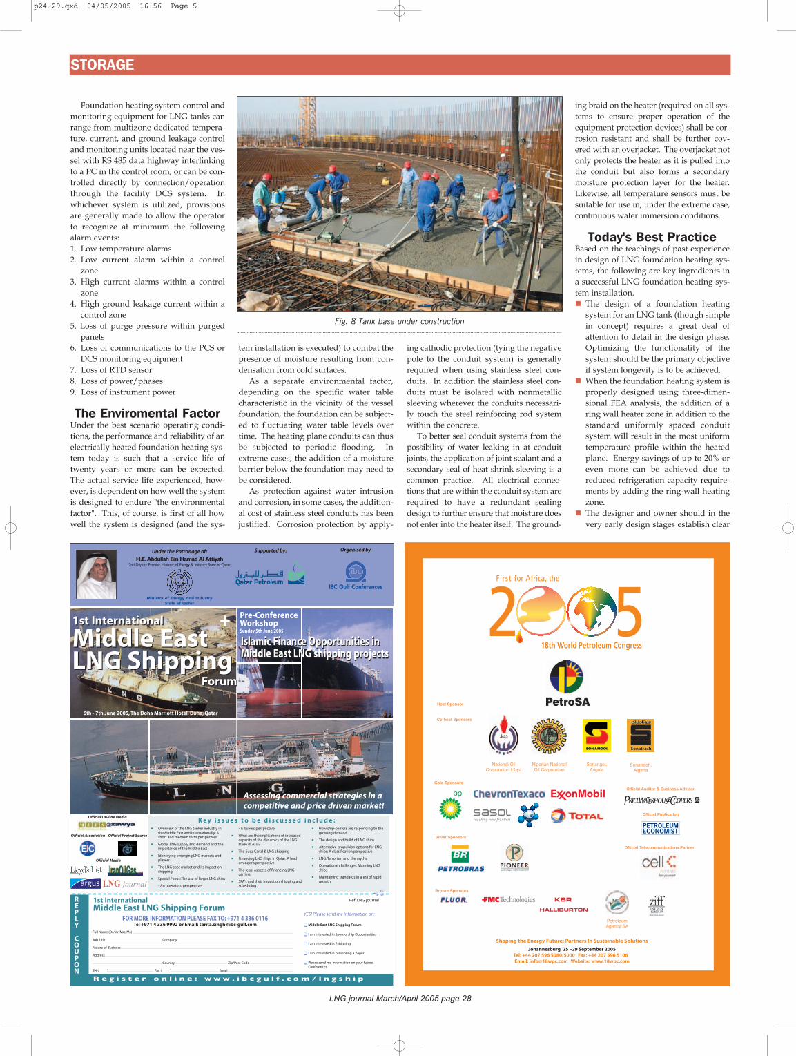
Fig. 8 Tank base under construction
IBC Gulf Conferences
Organised by
R e g i s t e r o n l i n e : w w w . i b c g u l f . c o m / l n g s h i p
1st International
Middle East LNG Shipping
Forum
1st International
Middle East LNG Shipping
Forum
6th - 7th June 2005, The Doha Marriott Hotel, Doha, Qatar
Ministry of Energy and IndustryState of Qatar
Supported by:Under the Patronage of:
H.E.Abdullah Bin Hamad Al Attiyah2nd Deputy Premier, Minister of Energy & Industry, State of Qatar
Assessing commercial strategies in a competitive and price driven market!
+ Pre-Conference WorkshopSunday 5th June 2005
Islamic Finance Opportunities inMiddle East LNG shipping projectsIslamic Finance Opportunities inMiddle East LNG shipping projects
K e y i s s u e s t o b e d i s c u s s e d i n c l u d e :
FOR MORE INFORMATION PLEASE FAX TO: +971 4 336 0116Tel +971 4 336 9992 or Email: [email protected]
Full Name (Dr/Mr/Mrs/Ms)
Job Title Company
Nature of Business
Address
Country Zip/Post Code
Tel ( ) Fax ( ) Email
YES! Please send me information on:
� Middle East LNG Shipping Forum
� I am interested in Sponsorship Opportunities
� I am interested in Exhibiting
� I am interested in presenting a paper
� Please send me information on your futureConferences
REPLY
COUPON
��Ref: LNG journal1st International
Middle East LNG Shipping Forum
� Overview of the LNG tanker industry inthe Middle East and internationally: Ashort and medium term perspective
� Global LNG supply and demand and theimportance of the Middle East
� Identifying emerging LNG markets andplayers
� The LNG spot market and its impact onshipping
� Special Focus: The use of larger LNG ships
- An operators’ perspective
- A buyers perspective
� What are the implications of increasedcapacity of the dynamics of the LNGtrade in Asia?
� The Suez Canal & LNG shipping
� Financing LNG ships in Qatar: A leadarranger's perspective
� The legal aspects of financing LNGcarriers
� SPA's and their impact on shipping andscheduling
� How ship-owners are responding to thegrowing demand
� The design and build of LNG ships
� Alternative propulsion options for LNGships: A classification perspective
� LNG: Terrorism and the myths
� Operational challenges: Manning LNGships
� Maintaining standards in a era of rapidgrowth
Official Project Source
Official On-line Media
Official Association
Official Media
p24-29.qxd 04/05/2005 16:56 Page 5

specifications for interrogation and monitoring of the heating system's performance to ensure that operators have a clear picture of the performance especially during possible abnormal operating condition scenarios.The high thermal inertia in the founda-tion mass makes fine tuning of the tem-perature control in a foundation h e a t -
ing system a process spanning weeks of observation. Patience is required.The power system should be designed with sufficient design margin to compensate for the removal of a speci-fied number of conduits from service without allowing localized freezing to occur.The effects of water entry into the con-
duit system must be anticipated and proper design allowances taken to en-sure continued operation in such cases.
ConclusionThe value in the use of state-of the artthree-dimensional FEA analysis to opti-mize the thermal design of foundationheating systems has been demonstrated.
Likewise, the power system can be opti-mized through the use of best practice ashas been described. Implementation ofthe optimization techniques presentedhere can result in improved operationalperformance, reduced energy cost, andenhanced system reliability for ownersand operators of LNG and other cryogenicvessel storage facilities.
LNG journal March/April 2005 page 29
LNGjournal
Vincent Schuhlis the head ofthe Frenchaffiliate ofThermon Man-u f a c t u r i n g
Company. He is a graduateof INPG with a Bachelor inMaterial Science. He hasmore than fifteen years ofextensive experience in heattracing applications for theoil and gas industry. He isrecognized expert for theIEC, for equipment used inhazardous areas, and a mem-ber of the French committeeof the UTE for normalizationfor the use of equipment inhazardous areas.
Gerard Grossis the head ofthe ElectricalDepartmentat the Engi-neering and
Process Division of SAIPEMSA in France. He is a gradu-ate of CELSA University witha Bachelor of Science inPower Engineering and alsoof the CNAM (National Con-servatory) in 1985. He hasover thirty years of extensiveexperience in staff manage-ment, engineering, construc-tion and project manage-ment, and the management ofdesign, development, con-struction, implementation,inspection and testing in theoil and gas industry.
LaurentDucoup is asenior engi-neer from theS A I P E Mgroup. He
graduated as an Engineer inSteel Structures (CHEM)from CHEC (Center of HighStudies of Construction -France). He has been work-ing for Technigaz for 10years and has been involvedin many LNG storage tankprojects, including currentTechnigaz projects in Spain,Egypt, India, China, andFrance. He was also involvedwith the Working Committeethat formulated a new Euro-pean code dealing with LNG storage tanks, due forpublication soon.
p24-29.qxd 04/05/2005 16:57 Page 6
Related Documents


