DESIGN AND SIMULATION OF HYDRAULIC SHAKING TABLE KHAIRULNIZAM BIN NGADIMON A project report submitted in partial fulfillment of the requirements for the award of the degree of Master of Engineering (Mechanical) Faculty of Mechanical Engineering University of Technology Malaysia 7 APRIL 2006

Welcome message from author
This document is posted to help you gain knowledge. Please leave a comment to let me know what you think about it! Share it to your friends and learn new things together.
Transcript

DESIGN AND SIMULATION OF HYDRAULIC SHAKING TABLE
KHAIRULNIZAM BIN NGADIMON
A project report submitted in partial fulfillment of the
requirements for the award of the degree of
Master of Engineering (Mechanical)
Faculty of Mechanical Engineering
University of Technology Malaysia
7 APRIL 2006

iii
To my beloved family,
The lover in you who brings my dreams comes true,
To my child Luqmanul Hakim and Fatin Nur Atikah, who have brought
a new level of love, patience and understanding
into our lives.

iv
ACKNOWLEDGEMENTS
First and above all, I am very grateful to Allah, with his blessing, allow me
to complete this project on time.
I would like to take this opportunity to express my deep sense of gratitude
and appreciation to my project advisor, Associate Professor Yahaya B. Ramli. His
endless help, useful information, support, advice and guidance have made it possible
for me to finish the project successfully.
I would also like to express my heartfelt thanks to my project co-advisor
Associate Professor Dr. Musa Mailah for the information and motivation to the
project. Not to forget Pn. Rosmawati from Structural Engineering Lab, Faculty of
Civil Engineering UTM Skudai, En. Asmadi from Bahagian Seismologi, Jabatan
Kajicuaca Malaysia for their expert advice. Also thanks to the technicians in the
structural lab for their guidance and technical advice. I am also indebted to Kolej
Universiti Teknologi Tun Hussein Onn and Jabatan Perkhidmatan Awam, Malaysia
for funding my Master study.
Finally, utmost thanks to my parents, my wife Siti Zubaidah and my lovely
son and daughter, there are no words that can replace their support, sacrifice and
encouragement. Last but not least to my colleagues and friends for the livelihood.
v
ABSTRACT
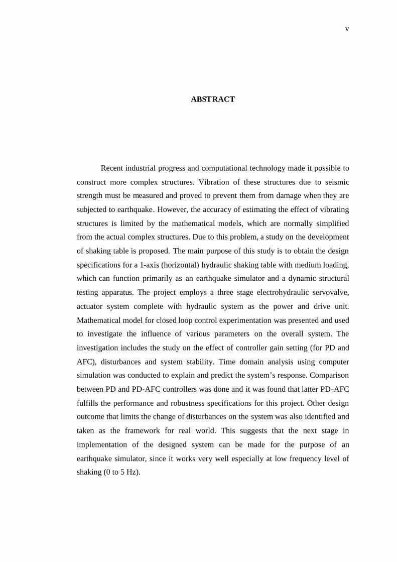
Recent industrial progress and computational technology made it possible to
construct more complex structures. Vibration of these structures due to seismic
strength must be measured and proved to prevent them from damage when they are
subjected to earthquake. However, the accuracy of estimating the effect of vibrating
structures is limited by the mathematical models, which are normally simplified
from the actual complex structures. Due to this problem, a study on the development
of shaking table is proposed. The main purpose of this study is to obtain the design
specifications for a 1-axis (horizontal) hydraulic shaking table with medium loading,
which can function primarily as an earthquake simulator and a dynamic structural
testing apparatus. The project employs a three stage electrohydraulic servovalve,
actuator system complete with hydraulic system as the power and drive unit.
Mathematical model for closed loop control experimentation was presented and used
to investigate the influence of various parameters on the overall system. The
investigation includes the study on the effect of controller gain setting (for PD and
AFC), disturbances and system stability. Time domain analysis using computer
simulation was conducted to explain and predict the system’s response. Comparison
between PD and PD-AFC controllers was done and it was found that latter PD-AFC
fulfills the performance and robustness specifications for this project. Other design
outcome that limits the change of disturbances on the system was also identified and
taken as the framework for real world. This suggests that the next stage in
implementation of the designed system can be made for the purpose of an
earthquake simulator, since it works very well especially at low frequency level of
shaking (0 to 5 Hz).

v
ABSTRAK
Perkembangan dan kemajuan teknologi terkini dalam bidang industri
dan perkomputeran membolehkan struktur bangunan yang lebih kompleks dibina.
Getaran struktur bangunan ini terhadap gegaran sismik perlu diukur dan dibuktikan
untuk mencegah daripada kerosakan teruk apabila gempa bumi sebenar berlaku.
Walaubagaimanapun, untuk struktur yang kompleks, penganggaran kesan
getarannya menggunakan model matematik adalah terhad disebabkan beberapa
anggapan dalam analisa dinamiknya. Disebabkan masalah ini, telah membawa
kepada perkembangan alat lantai gegaran hidraulik. Tujuan utama kajian ini adalah
untuk merekabentuk spesifikasi alat lantai gegaran hidraulik 1 paksi (mendatar) pada
skala beban yang sederhana. Ianya digunakan untuk tujuan simulator gempa bumi
dan untuk menguji pelakuan dinamik sesuatu model atau prototaip struktur. Projek
ini menggunakan peringkat ketiga injap servo elektrohidraulik, sistem penggerak
lelurus dan sistem hidraulik sebagai unit kuasa dan penggerak. Model matematik
untuk ujian kawalan gelung tertutup telah dibincangkan dan digunakan untuk
mengkaji kesan beberapa parameter terhadap keseluruhan sistem. Kesan yang dikaji
termasuk penetapan pemalar pengawal, kesan pengawal PD dan AFC, kesan
gangguan dan kestabilan sistem. Analisa dalam domain masa menggunakan simulasi
komputer telah dijalankan untuk mengenalpasti kelakuan sistem. Perbandingan
antara pengawal PD dan PD-AFC dikaji dan didapati pengawal PD-AFC memenuhi
keperluan spesifikasi sambutan masa dan kelasakannya untuk kajian ini. Parameter
lain hasil daripada simulasi yang menghadkan kelakuan sistem daripada kelakuan
asalnya juga telah dikenalpasti dan dijadikan asas dalam aplikasi sebenar. Secara
keseluruhannya, fasa untuk membangunkan sistem yang telah direkabentuk ini boleh
dilakukan untuk tujuan simulasi gempa bumi kerana ianya berfungsi dengan baik
terutamanya pada lingkungan frekuensi 0 hingga 5 Hz.

vi
TABLE OF CONTENTS
CHAPTER TITLE PAGE
TITLE PAGE i
DECLARATION ii
DEDICATION iii
ACKNOWLEDGEMENTS iv
ABSTRACT v
TABLE OF CONTENTS vi
LIST OF TABLES xi
LIST OF FIGURES xii
LIST OF SYMBOLS/ABBREVIATIONS xvii
LIST OF APPENDICES xxi
1 INTRODUCTION TO SHAKING TABLES
1.0 Project Introduction 1
1.1 Objectives of study 2
1.2 Scope of study 3
1.3 Operation of shaking tables 5
1.4 Types of Hydraulic Shaking Table 7
1.4.1 INOVA-Servo hydraulic testing system 7
1.4.2 ANCO-Model R150-142 Shaking table 9
1.4.3 NIED-E Defense Facility in Japan 10
1.4 Project Scheduling 12

vii
2 LITERATURE REVIEWS OF EARTHQUAKES
PARAMETER
2.0 Introduction 13
2.1 Magnitude and Intensity of Earthquakes 15
2.2 Representation of Ground Motion 16
2.3 Time Domain Analysis of Earthquake
Ground Motion 18
2.4 Earthquake Estimation using Shaking Table Test 19
2.5 The Use of Servovalve Actuator in Earthquakes
Response Test 20
2.5.1 Testing System in Displacement Control 21
2.6 Summary 24
3 DESIGN METHODOLOGY OF HYDRAULIC
SHAKING TABLE
3.0 Introduction 25
3.1 Design Steps of Hydraulic Circuit 26
3.2 Selection of Hydraulic Fluids 28
3.2.1 Effect of Bulk Modulus 28
3.2.2 Lubricating ability 29
3.3 Actuator Design 29
3.3.1 Calculation of Velocity and
Cylinder’s Pressure 30
3.4 Conductor Sizing for Flow Rate Requirements 32
3.4.1 Pressure Rating of Conductors 33
3.4.2 Steel Tubing Conductor 34
3.5 Pressure Relief Valve 35

viii
3.6 Pump Performance 36
3.6.1 Pump Selection 38
3.7 Summary 40
4 ACTUAL DESIGN CALCULATION
4.0 Introduction 41
4.1 Determination of Dynamic Force Acting
on the Actuator 41
4.2 Determination of Minimum Size of
Piston Diameter 43
4.3 Selection of Cylinder’s Mounting 44
4.4 Determination of Minimum Rod Diameter 45
4.5 Determination of Flow Rate at Different
Frequency Rating 47
4.6 Selection of Conductor for Pressure Line 52
4.7 Selection of Flexible Hydraulic Hose 53
4.8 Calculation of Theoretical Pump Power 53
4.9 Selection of Pump 56
4.10 Selection of Motor 58
4.11 Design of Hydraulic Reservoir 59
4.12 Selection of Conductor for Pump Suction Line 61
4.13 Selection of Hydraulic Fluid 62
4.14 Filter Positioning 63
4.15 Cooling System 63
4.16 The Shaking Table and Actuator Structure 65
4.17 Roller Rail System 67
4.18 Final Specifications of the Designed System 67
4.19 Summary 70

ix
5 SYSTEM MODELING OF HYDRAULIC SHAKING TABLE
5.0 Introduction 71
5.1 Determination of Natural Frequency and
Damping Ratio of Hydraulic Servomechanism 72
5.2 Actual Modeling of Servovalve Used in the Study 75
5.2.1 Servovalve Flow Property 77
5.2.2 Parameter Identification 80
5.2.3 Servovalve Transfer Function 81
5.3 The Proposed Controller Design 83
5.3.1 PID Controller 84
5.3.2 Active Force Control (AFC ) Controller 89
5.4 Interconnection of Servovalve Controller 86
5.5 Interconnection of Servovalve and
Hydraulic Actuator 88
5.6 Overall System Dynamics 95
5.7 Summary 97
6 SIMULATION
6.0 Introduction 98
6.1 Simulation of Servovalve 98
6.1.1 Performance Specifications 99
6.2 Simulation to Step Input Signal 101
6.3 Response Behavior with Sine Wave Input 103
6.4 Simulation of Servovalve and Actuator 105
6.4.1 Performance Specifications 106
6.5 Response Test without Any Controller 107
6.6 Response of PD-AFC controller to
Step Input Signal 109

x
6.7 Response of PD-AFC Controller to Sine Wave 111
6.8 Robustness of PD-AFC to Disturbances 114
6.8.1 Effect of Shaking Table Loading 114
6.8.2 Effect of Leakage 117
6.8.3 Effect of Dry and Viscous Friction 120
6.8.4 Effect of Hydraulic Fluid Compressibility 122
6.8.5 Effect of Change in Volume 125
6.9 Stability of the System 127
6.9 Summary 129
7 CONCLUSION 131 - 132
REFERENCES 133 - 134
Appendices A – M 135 - 165
xi
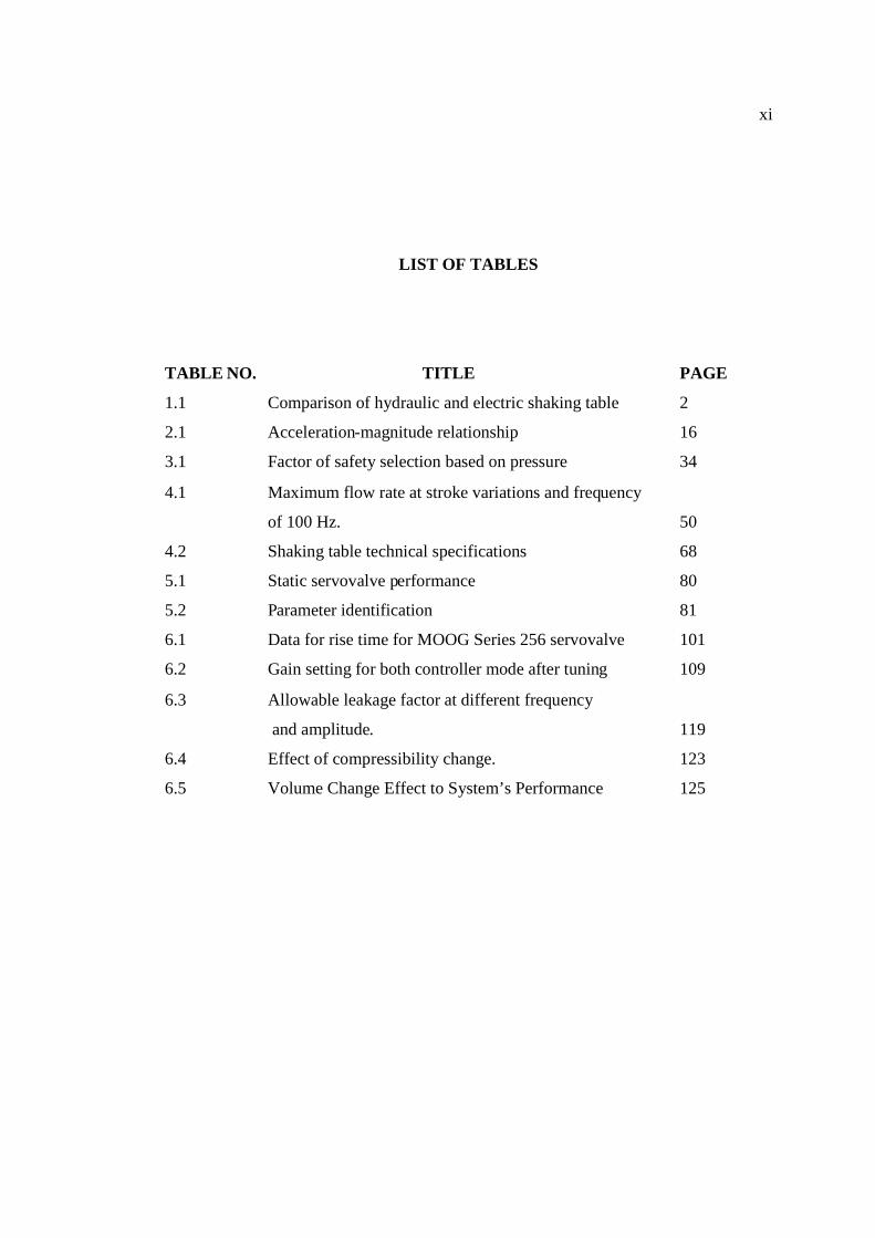
LIST OF TABLES
TABLE NO. TITLE PAGE
1.1 Comparison of hydraulic and electric shaking table 2
2.1 Acceleration-magnitude relationship 16
3.1 Factor of safety selection based on pressure 34
4.1 Maximum flow rate at stroke variations and frequency
of 100 Hz. 50
4.2 Shaking table technical specifications 68
5.1 Static servovalve performance 80
5.2 Parameter identification 81
6.1 Data for rise time for MOOG Series 256 servovalve 101
6.2 Gain setting for both controller mode after tuning 109
6.3 Allowable leakage factor at different frequency
and amplitude. 119
6.4 Effect of compressibility change. 123
6.5 Volume Change Effect to System’s Performance 125

xii
LIST OF FIGURES
FIGURE NO. TITLE PAGE
1.1 All electric shaking table 6
1.2 Servo hydraulic shaking table 6
1.3 Manual shaking table 6
1.4 6 Degree of Freedom Shaking System 8
1.5 3 Degree of Freedom Shaking System 8
1.6 1 Degree of Freedom Shaking System 8
1.7 Close up of the 22 Kip actuator with 3 Stage
Servo Valve 9
1.8 NIED Earthquake Simulator from Japan 11
2.1 Seismic waves P and S wave 14
2.2 Principal term used in describing earthquakes
(a) Geometry (b) transmission 14
2.3 Response Spectra for the 1940 El Centro earthquake 17
2.4 Sample of strong earthquake motion in Time Domain
Analysis 19
2.5 Schematic arrangement of actuator controlled system 22
2.6 System modeling for the servo actuator test 22
2.7 Response of the system subjected to a 12.7 cm
sine wave input (0 to 10 Hz) 23

xiii
3.1 Extending and retracting phase of actuator 30
3.2 Operation of pressure relief valve 36
3.3 Vane pump 39
4.1 Schematic diagram of the actuator and shaking table 42
4.2 Intermediate trunnion mounts. 44
4.3 Summary of the selected cylinder dimension 46
4.4 Spring vibration system 48
4.5 MATLAB programming code 49
4.6 Flow rate vs. frequency at stroke of 2-inch 52
4.7 Selection of double rod double acting cylinder 51
4.8 Hydraulic cycle operating at maximum frequency
of 20 Hz. 55
4.9 Internal design features of the hydraulic reservoir 60
4.10 Baffle plate controls the direction of flow in the
reservoir. 60
4.11 Proposed layout for the power pack unit 61
4.12 Positioning of filters in the system 64
4.13 Oil to air cooler (cross flow type). 65
4.14 Plate ASTM A36 Dimensions. 66
4.15 Hydraulic circuit for the hydraulic shaking table. 69
5.1 Valve and actuator arrangement 72
5.2 Cutaway view of a 3 stage model 256
MOOG Servovalve. 76
5.3 Schematic of main stage spool valve with actuator
(a) load flow orifice (b) leakage flow orifice 77
5.4 Flow curve for the MTS 256.25A-02 Servovalve 80
5.5 Schematic diagram of AFC loop in the modeling 85

xiv
5.6 3 Stage servovalve and actuator with feedback 87
5.7 Block diagram model of 3-stage servovalve 88
5.8 Equivalent scheme for hydraulic actuator 88
5.9 Equivalent scheme servovalve and actuator 89
5.10 Influence of loading at the actuator 89
5.11 Equivalent scheme including compressibility and
balance flow. 91
5.12 Equivalent scheme including damping factor 92
5.13 Feedback loop from actuator 93
5.14 Introduction of PID control block 94
5.15 The simplified transfer function for the combined system 95
5.16 Step response of the overall model
(a) MATLAB programming (b) Simulink model 96
6.1 Model of 256 MOOG Servovalve in Simulink. 100
6.2 Rise time plot for MOOG servovalve model 256.25A-02 101
6.3 Final fine-tuning of PID controller
(a) Opening in mm (b) opening in percentage 102
6.4 Enlarge view of overshoot. 102
6.5 Sine wave output response at 100% opening
(a) frequency 1 Hz. (b) frequency 5 Hz. 104
6.6 Sine wave output response at 10 mm opening
(a) at frequency 13 Hz (b) at frequency 20 Hz. 104
6.7 Simulink model of hydraulic shaking table. 106
6.8 (a) Removal of PID block
(b) The AFC Control switch is turn off 108
6.9 Response without any controller. 108

xv
6.10 Responses at 100% opening using step input signal
(a)=700 MPa (b) =200 MPa 108
6.11 Response after the implementation of controller mode;
(a) PD controller only (b) PD-AFC Controller. 110
6.12 Response at low frequency for PD Control mode
(a) at frequency 1 Hz. (b) at frequency 5 Hz. 111
6.13 Response at intermediate and high frequency
using PD Controller.
(a) at frequency 10 Hz (b) at frequency 20 Hz 111
6.14 Response at low frequency using PD-AFC Control
(a) frequency 1.5 Hz (b) frequency 5 Hz 112
6.15 Response at intermediate and high frequency using
PD-AFC Controller(a) at frequency 10 Hz (b) at frequency 20 Hz. 112
6.16 Response to a random wave signal
using PD-AFC Control 113
6.17 (a) The block setting for changing the weight (in kg)
(b) Mass block diagram in SIMULINK. 115
6.18 Responses at test model weight 500 kg.
(a) frequency 1.5 Hz (b) frequency 20 Hz. 116
6.19 Responses at test model weight 2830 kg
(a) frequency 1.5 Hz (b) frequency 20 Hz. 116
6.20 (a) Block for adjusting leakage factor.
(b) Model representation for leakage in Simulink 117
6.21 Responses using PD-AFC at frequency 2 Hz.
(a) L=2 (b) L=160 118
6.22 Responses using PD-AFC at frequency 10 Hz.
(a) L=2 (b) L=20 118

xvi
6.23 Step response using PD-AFC
(a) L=30 (b) L=5 118
6.24 Leakage control method 120
6.25 Response at the onset of dry and viscous friction
(a) step input test (b)sine wave at f = 5 Hz. 121
6.26 Response using PD-AFC at constant mass of 4330 kg.
(a)=700 MN/m2 (b) =692 MN/m2 123
6.27 Response of PD-AFC at =692 MN/m2
(a) mass of 500 kg (b) mass of 4330 kg 123
6.28 System response for the load of 4330 kg
(a) V=20,000 mm3 (b) V=171806 mm3 126
6.29 Routh diagram. 127
6.30 Parameter positioning in Routh diagram. 129

xvii
LIST OF SYMBOLS / ABBREVIATIONS
- Bulk modulus
V - Volume
dP - Change in pressure
dV - Change in volume
F - Force
- Coefficient of friction
N - Normal force
EQ - Input flow rate into the cylinder’s blank end side
v - Extending velocity of the cylinder rod.
Eq - Output flow rate from the cylinder’s rod end side
'a - Cross sectional area of the piston on the rod end side
A - Cross sectional area of the piston on the blank end side
D - Diameter of piston on the blank end side
d - Diameter of piston on the rod end side
1p - Pressure on the blank end side
2p - Pressure on the rod end side
RQ - Output flow rate from the cylinder’s blank end side
u - Extending velocity of the cylinder rod
Rq - Input flow rate into the cylinder’s rod end side
P - Pressure
Q - Flow rate
averagev - Average extending velocity
BP - Burst pressure
xviii
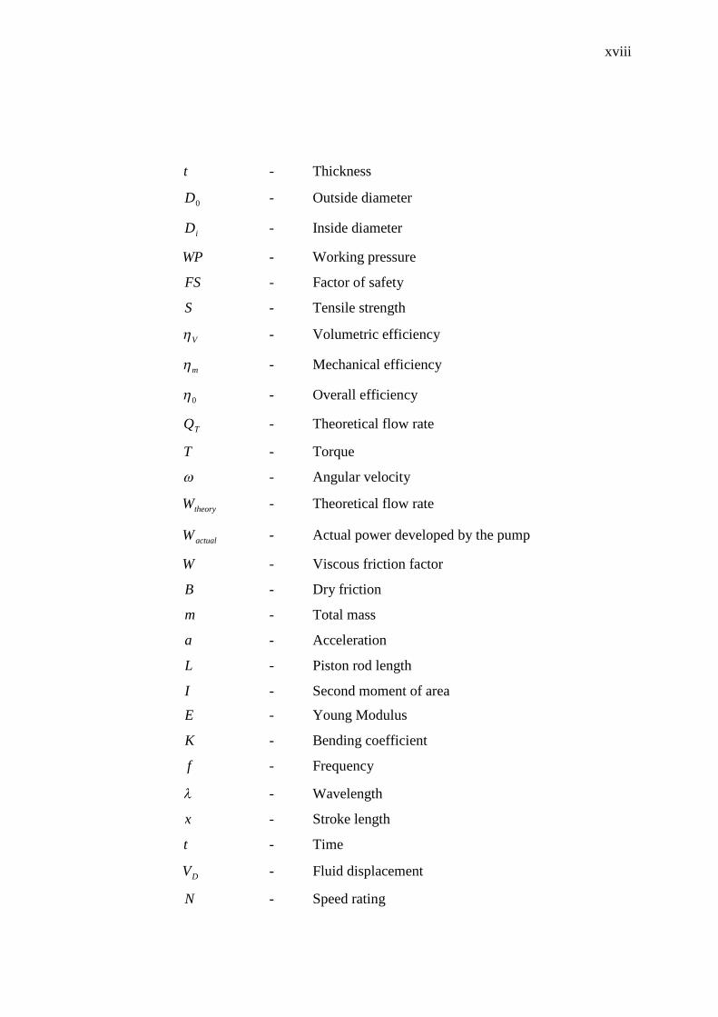
t - Thickness
0D - Outside diameter
iD - Inside diameter
WP - Working pressure
FS - Factor of safety
S - Tensile strength
V - Volumetric efficiency
m - Mechanical efficiency
0 - Overall efficiency
TQ - Theoretical flow rate
T - Torque
- Angular velocity
theoryW - Theoretical flow rate
actualW - Actual power developed by the pump
W - Viscous friction factor
B - Dry friction
m - Total mass
a - Acceleration
L - Piston rod length
I - Second moment of area
E - Young Modulus
K - Bending coefficient
f - Frequency
- Wavelength
x - Stroke length
t - Time
DV - Fluid displacement
N - Speed rating

xix
dq CC , - Discharge coefficient
SP - Supply pressure
TP - Load pressure
- Density
y - Additional displacement
Vx - Pilot spool displacement
mx - Main spool displacement
ecr ,, - Geometric coefficient
w - Valve spool perimeter
VPV KK , - Valve flow gain
T - Time constant
iV - Voltage error signal
PQ - Pilot stage flow rate
mA - Effective area of main spool valve
dK - Derivative gain
PK - Proportional gain
iK - Integral gain
EM - Estimated mass
aF - Measured force from sensor
activeF - Active force
aK - Servovalve controller gain
fK - LVDT 1 gain
pK - LVDT 2 gain
inV - Input voltage command signal
balQ - Compression flow rate
pistonQ - Volume oil flow because of piston movement

xx
totalQ - Total flow rate into actuator
rf - Natural frequency (Hz.)
VF - Viscous friction force
L - Leakage factor
leakQ - Leakage flow rate
CG - Overall reduced transfer function
aG - Sensor transfer function
n - Natural frequency (rad/sec)
st - Settling time
rt - Rise time
g - Gravity = 9.81 m/s2

xxi
LIST OF APPENDICES
APPENDIX TITLE PAGE
A Gantt chart of work for first and second 135 - 137
semester.
B Modified Mercalli (MM) Scale 138 - 139
C Linear change of acceleration method 140 - 141
D Cylinder standard BS 5785,
Eaton Actuator and accessories dimension 142 - 145
E Standard hydraulic hose from Parker dimension
and technical data. 146 - 147
F VMQ Series vane pump performance data and
dimensions. 148 - 149
G D.C Motor from ABB Motors Inc. technical data
and dimensions. 150 - 151
H Typical properties of selected engineering materials 152
I Properties of rolled-steel shapes 153

xxii
J Assembly drawing for shaking table and
actuators structure. 155 - 156
K Aluminium cassette and roller shoes
technical data and dimensions. 157 - 158
L Series 256 servovalves product specifications. 159 - 163
M MATLAB close loop programming code. 164 - 165

CHAPTER 1
INTRODUCTION TO SHAKING TABLES
1.0 Project Introduction
Shaking table is a machine that can perform realistic simulation of
earthquakes or any other dynamic loading imposed to the test model or structures.
There are many types of shaking table but it can be classify to its method of
vibration actuation by electrically driven, hydraulically driven and manually driven
shaking table. Shaking table is related to earthquake since much of its parameter is
custom designed to the earthquake’s parameter such as acceleration, displacement,
frequency and stroke.
However hydraulically driven shaking table have more advantages from
other method of actuation. Table 1.1 lists some of the advantages of using hydraulic
shaking table.

2
Table 1.1: Comparison of hydraulic and electric shaking table
Hydraulic shaking table Electric shaking table
1. Can be used for any size of load 1. Limited to small and medium size
load.
2. Some of the parameter such as stroke,
velocity, frequency can be changed
easily depend on application.
2. Most of the time , the parameter have
been set cannot be changed.
1.1 Objectives of Study
The main objectives of this study are:
1. To design a medium hydraulically driven shaking table to be used as an
earthquake simulator.
2. To perform simulation of the designed hydraulic shaking table using
techniques of dynamic system analysis especially in time domain method to
investigate the linearity characteristics between input signal and the desired
output.

3
1.2 Scope of Study
The scope of this study are:
1. Investigate the nature and properties of earthquake and its relation to the
parameter to be used in the design of hydraulic shaking table.
2. Design a complete hydraulic circuit of a medium scale simple hydraulic
shaking table based on selected parameter.
3. Derive the dynamic equation of the hydraulic shaking system and develop a
mathematical model for the overall system.
4. Select a proper practical value for each parameter assigned in the
mathematical model.
5. Perform computer simulation using MATLAB Simulink on the time domain
analysis, feedback system design and to check the stability of the overall
system.
6. All simulations are performed within the limitation of the selected parameter
such as maximum load range, frequency range, shaking axis and maximum
acceleration range.
In this project, the works are bounded in the frequency range of 20 Hz,
maximum acceleration of 1.5g and maximum load of 4330 kg. Main component of
hydraulic circuit and the hydraulic circuit diagrams have been designed and
discussed.
Mathematical modeling of this project is being done on the servovalve and
hydraulic servomechanism using Laplace Transform. Separate modeling will be

4
done that is modeling of servovalve and modeling of actuator mechanism. Not only
that due to nonlinearities in the servovalve, it is better to do a separate modeling of
servovalve so that proper steps can be applied in order to take care of the
nonlinearities. Then the modeling will be combined using block diagram and can be
programmed in the Simulink.
Simulation part will be done in Semester II and the program that will be used
is MATLAB Simulink. In this program the overall block diagram will be
programmed in it and input signal will be imposed on the block diagram. Types of
input signal to be tested are Step, Sinusoidal and Random input signals. Simulation
also being done separately that is simulation of servovalve and combined simulation
of servovalve and actuator to investigate the individual response. A proposed
controller will be added. Then it will be compared and tested against disturbance
effect on the system. Finally, the controller that fulfills the performance and
robustness specifications will be selected. In the simulation, some design limitation
and outcomes will be investigated in order to compensate for any practical changes
that might occur during the actual condition.
This project is important to get the preliminary design of hydraulic shaking
table of medium scale that have many benefit to the future work and development of
this machine. Future research in this field is interesting since it can develop more
realistic design of hydraulic shaking table.

5
1.3 Operation of Shaking Tables
Shaking table is a mechanical device that is used to test any structures under
seismic or other types of dynamic loading such as step load, sinusoidal varying
force, or random load. If the shaking table is designed primarily to test civil structure
under seismic loading, then it is also called earthquake simulator. Normally test
model are developed to understand the effects of different parameters and process
that leads to failure of prototype at a real time. If the test model are performed under
gravitational field of earth, then it is subjected to the shaking table test, whereas if
the model tests are performed under higher gravitational field then it is subjected to
centrifugal test. Therefore shaking table test is an experimental approach in order to
assure the validity of the theoretical estimation of the response of the structure with
the exact dynamic characteristics thus to develop the safety margin of design for the
structure.
In the shaking table test, test specimens are placed on the table and it is fixed
by mechanical fastener or artificial soil compacted on the table. Then the structure
will experience a shaking process at a certain frequency values until a certain time
limit set by the operator. The earthquake simulator or shaking table has a wide range
of applications such as:
Models of buildings or structure in a given scale, subjected to actual
earthquake.
Models of power supply or industrial buildings under specific
dynamic loading conditions.
Mechanical equipment and transportation facilities test
Mechanical testing and development of dampers for power
transmission lines.

6
Shaking table device operates in various means. Some of them use all-
electric servo motor driven type as in Figure 1.1, servo hydraulic means of actuation
for high mass payloads such as in Figure 1.2 and manually operated shaking table as
in Figure 1.3 that use external applied force to shake the table.
Figure 1.1: Electric shaking table [1] Figure 1.2: Servo hydraulic table [1]
Figure 1.3: Manual shaking table [2]

7
1.4 Types of hydraulic shaking table
Since most of the shaking table is used as an earthquake simulator purposes,
there is some of them been used as an apparatus to test the response or frequency of
a structure or a test model. This permits the versatility and wide range of shaking
table model. Shaking table is grouped based on its actuator power, frequency range
and the maximum load it can handle. Normally it is classified either in small scale,
medium scale or a large scale load. Small scale load hydraulic shaking table ranging
from 0 to 1000 kg load whereas for medium scale can range from 1000 to 5000 kg
and large scale range is greater than 5000 kg load. Section 1.4.1, 1.4.2 and 1.4.3
shows some manufacturer of hydraulic shaking table in the market.
1.4.1 INOVA – Servo hydraulic Testing System
INOVA is one of the leaders in seismic simulations for earthquake and
structural research. Their seismic simulator called “Seismic Shaking Table” is used
for seismic qualification and seismic simulation in civil engineering and academic
research into earthquake. INOVA’s seismic shaking tables are designed for
earthquake testing of a wide range of test applications. INOVA systems can be used
to simulate a variety of seismic tests as well as evaluating many different types of
components in vibration and shaking environments. The DOF refers to the number
of shaking axis the machine can apply to the test model. Typical configurations are
one, two, three and six degrees of freedom (DOF) as in Figure 1.4, 1.5 and 1.6.

8
Figure 1.4: 6 DOF shaking system [3] Figure 1.5: 3 DOF shaking system [3]
Figure 1.6: 1 DOF shaking system [3]
The six degrees of freedom hydraulic shaking table machine is intended for
general-purpose vibration tests. It is classified as a large-scale machine .In this
machine, test model can be loaded in one axis or simultaneous axes. Test can be run
in constant amplitude, block program or full simulation with combination of more
than one wave profiles to be simulated simultaneously.

9
1.4.2 ANCO-Model R150.142 shaking table
This servo-hydraulic type-shaking table was used by Columbia University. It
is a medium scale shaking table facility to conduct experimentation in structural
dynamics and particularly to monitor and actively control structures subjected to
earthquake ground motion or other force excitations. The table which was custom
designed by ANCO Engineers for the Civil and Structural Research Engineering
capable of carrying maximum three ton payload on the 5ft x 5 ft table size. The table
is able to shake two ton payload with 3g acceleration (three times the acceleration of
gravity in horizontal direction). Thus the table is ideally suited to seismic
application. The hydraulic actuator can produce a stroke of maximum 10 inch (± 5
inch). The actuator has a three-stage servo-valve controlled by an analog inner-loop
control system and a digital outer loop control system (acceleration feedback based).
Figure 1.7: Close up of the 22 kip actuator with 3 stage servo valve [1]

10
Specifications of ANCO-Model R150.142;
1. Shaking direction : Uni-axial horizontal motion
2. Table size : 5 ft x 5 ft.
3. Peak to peak displacement : 10 inches of double amplitude
4. Peak velocity : 60 inch / sec.
5. Peak acceleration : 3.0g
6. Maximum test specimen weight : 2 tonne
7. Frequency range : 0 – 100 Hz.
8. Servo valve : 3-stage electrohydraulic servovalve.
1.4.3 NIED-E Defense Facility in Japan
Recently due to a number of major damage caused by earthquakes and
structural buildings failure cases in Japan have led to the start of NIED-E Defense
project. National Research Institute for Earth Science and Disaster Prevention
(NIED) have three main objectives that are to conduct research and experimentation
on the structural building failure test, developing three dimensional motion of the
simulated real earthquake from past record earthquake data and build full scale
model to predict the real behavior of the damage. NIED use a big scale shaking table
facility as in Figure 1.8 to test their ready-made full-scale model. Some of the
specifications of the shaking table facilities are;
Shaking table type : 3D Full scale earthquake testing facility
Payload : 1200 ton
Shaking table size : 20m x 15m

11
Driving type : Accumulator charge, Electro-hydraulic
Servo control
Shaking direction : X and Y Horizontal, Z – Vertical
Maximum acceleration at
maximum loading. : X, Y Horizontal is > 900 cm/s2
Z-Vertical is >1500 cm/s2
Maximum displacement : X, Y Horizontal is ±100 cm
Z-Vertical is ±50 cm
Figure 1.8: NIED earthquake simulator from Japan [4]

12
1.4 Project Scheduling
This project will be done within two semesters. Thus, breakdown of work
structures must be implemented to make sure all the work being done within its
allocated time. In the first Semester, initial literature research work will be done.
This is to get a better picture on how to implement the scope of study number one
until three. In Semester two, scope of study number four until six was performed.
The breakdown of work structures for Semester one and two are attached in the
Appendix A.
Related Documents