Paper ID: 192, Page 1 DESIGN AND RATING OF AN EVAPORATOR FOR WASTE HEAT RECOVERY ORGANIC RANKINE CYCLE USING SES36 Alihan Kaya 1 *, Marija Lazova 1 and Michel De Paepe 1 1 Ghent University, Department of Flow, Heat and Combustion Mechanics, Ghent, Belgium e-mail: [email protected] * Corresponding Author ABSTRACT The paper presents a design and rating study of a 4MW evaporator having plain horizontal carbon steel tubes having diameters of 25,4 mm, 31,8 mm and 38 mm, to be used in waste heat recovery via Organic Rankine cycle (ORC). SES36 is chosen as working fluid due to its low boiling point, which makes it suitable for low-grade waste heat recovery with subcritical ORCs. Waste heat carrier industrial air arrives at the evaporator bundle at 280°C. Inlet temperature of the working fluid is 40°C and the evaporation occurs at 125°C and 1,09 MPa. Furthermore, a design sensitivity analysis is made by means of using 13 different in-tube flow boiling correlations. The resulting design and rating parameters yielded by each correlation are compared to each other. By those means, a design error margin of various thermo-hydraulic heat exchanger parameters is revealed, when different in-tube flow boiling heat transfer calculation methods are used. The change in the error margins are investigated with respect to changing tube outer diameter, tube wall thickness, fin density and tube layout (staggered and inline). 1. INTRODUCTION Waste heat recovery as an alternative energy source is receiving more and more attention from the industry and scientific world, as the energy shortage and environmental concerns in the world are rising. Organic Rankine cycles (ORCs) are promising applications for waste heat recovery, due to their heat recovery efficiencies and environmental-friendly features (Quoilin et al., 2013). ORCs are applicable with a wide range of waste heat sources rooting from industrial operations such as metallurgical industry, incinerators, combustion engines, annealing furnaces, drying, baking, cement production etc. ORCs are typically being applied on waste heat sources with the temperature range from 100°C up to 400°C, by being usually referred as low-temperature waste heat (100°C-250°C) and high-temperature waste heat (250°C-400°C). ORCs have a similar working principal with the conventional Rankine cycle which utilizes water or steam, however they utilize organic fluids as working fluid. Two among the most commonly used zero ozone depletion potential (ODP) working fluids for low-grade waste heat recovery are R245fa and Solkatherm® SES36. Their thermodynamic and environmental properties can be seen in the Table 1. Table 1: Properties of proposed fluids Working Fluid GWP ASHRAE Criteria M. Mass (g.mol -1 ) Boiling Point (K) T crit (K) P crit (MPa) R245fa 950 B1 134,05 288,05 427,2 3,64 Solkatherm® SES36 3710 Non-Flammable 184,53 308,79 450,7 2,85 The case-specific working conditions are the main determining parameters for an ORC system design. The efficiency of the cycle strongly depends on the considered working fluid. A reasonable selection process can be done by taking the fluids’ thermodynamic, stability, safety, legislative and environmental aspects into consideration for a particular case. Moreover, the critical temperature and brought to you by CORE View metadata, citation and similar papers at core.ac.uk provided by Ghent University Academic Bibliography

Welcome message from author
This document is posted to help you gain knowledge. Please leave a comment to let me know what you think about it! Share it to your friends and learn new things together.
Transcript

Paper ID: 192, Page 1
DESIGN AND RATING OF AN EVAPORATOR FOR WASTE HEAT
RECOVERY ORGANIC RANKINE CYCLE USING SES36
Alihan Kaya1*, Marija Lazova
1 and Michel De Paepe
1
1Ghent University,
Department of Flow, Heat and Combustion Mechanics,
Ghent, Belgium
e-mail: [email protected]
* Corresponding Author
ABSTRACT
The paper presents a design and rating study of a 4MW evaporator having plain horizontal carbon
steel tubes having diameters of 25,4 mm, 31,8 mm and 38 mm, to be used in waste heat recovery via
Organic Rankine cycle (ORC). SES36 is chosen as working fluid due to its low boiling point, which
makes it suitable for low-grade waste heat recovery with subcritical ORCs. Waste heat carrier
industrial air arrives at the evaporator bundle at 280°C. Inlet temperature of the working fluid is 40°C
and the evaporation occurs at 125°C and 1,09 MPa. Furthermore, a design sensitivity analysis is made
by means of using 13 different in-tube flow boiling correlations. The resulting design and rating
parameters yielded by each correlation are compared to each other. By those means, a design error
margin of various thermo-hydraulic heat exchanger parameters is revealed, when different in-tube
flow boiling heat transfer calculation methods are used. The change in the error margins are
investigated with respect to changing tube outer diameter, tube wall thickness, fin density and tube
layout (staggered and inline).
1. INTRODUCTION
Waste heat recovery as an alternative energy source is receiving more and more attention from the
industry and scientific world, as the energy shortage and environmental concerns in the world are
rising. Organic Rankine cycles (ORCs) are promising applications for waste heat recovery, due to their
heat recovery efficiencies and environmental-friendly features (Quoilin et al., 2013). ORCs are
applicable with a wide range of waste heat sources rooting from industrial operations such as
metallurgical industry, incinerators, combustion engines, annealing furnaces, drying, baking, cement
production etc. ORCs are typically being applied on waste heat sources with the temperature range
from 100°C up to 400°C, by being usually referred as low-temperature waste heat (100°C-250°C) and
high-temperature waste heat (250°C-400°C). ORCs have a similar working principal with the
conventional Rankine cycle which utilizes water or steam, however they utilize organic fluids as
working fluid. Two among the most commonly used zero ozone depletion potential (ODP) working
fluids for low-grade waste heat recovery are R245fa and Solkatherm® SES36. Their thermodynamic
and environmental properties can be seen in the Table 1.
Table 1: Properties of proposed fluids
Working Fluid GWP ASHRAE
Criteria M. Mass (g.mol
-1) Boiling Point (K)
Tcrit
(K)
Pcrit
(MPa)
R245fa 950 B1 134,05 288,05 427,2 3,64
Solkatherm® SES36 3710 Non-Flammable 184,53 308,79 450,7 2,85
The case-specific working conditions are the main determining parameters for an ORC system design.
The efficiency of the cycle strongly depends on the considered working fluid. A reasonable selection
process can be done by taking the fluids’ thermodynamic, stability, safety, legislative and
environmental aspects into consideration for a particular case. Moreover, the critical temperature and
brought to you by COREView metadata, citation and similar papers at core.ac.uk
provided by Ghent University Academic Bibliography

Paper ID: 192, Page 2
critical pressure values of the working fluid are the main criterion for distinguishing the cycle
conditions (subcritical, transcritical and supercritical) of an ORC. R245fa is reported to be a suitable
refrigerant for ORC applications by various researchers (Maalouf et al., 2012; Saleh et al., 2007;
Shengjun et al., 2011; Liu et al., 2012). Although, there are empirical examples of promising ORC
efficiency of SES36 (Mikielewicz et al., 2012; Mikielewicz, 2010; Riva et al., 2006; Siddiqi and
Atakan, 2011; Galvez, 2009), the ORC research with SES36 is still at its infancy. With the light of its
reported promising features in accordance to the aforementioned aspects, Solkatherm® SES36 is
chosen as the working fluid for the present study related to the subcritical ORC evaporators.
Waste heat recovery can be performed efficiently through a direct evaporator (e.g. finned tube
bundles) where the hot flue gas coming from a heat source (Ribatski and Thome, 2007) is in direct
contact with the heat exchanger outer surface. However, the thermodynamic efficiency of an
evaporator relies on heat transfer and pressure drops, the sizing of an evaporator needs to be performed
accordingly (Quoilin et al., 2013). In a design problem, the accuracy of the design method might have
a significant impact on the aspects related to heat transfer and thermo-economic efficiency. A too
small sized evaporator not capable to perform a complete evaporation might cause turbine or expander
damage in some cases. On the other hand, a too large evaporator will cause excessive working fluid
superheating, which may lead to a negative impact on system performance and a higher heat
exchanger cost (Fischer, 2011). Design of evaporators is often being done by means of commercial
software, where various generally applicable calculation methods are implemented, yet the methods
are usually undisclosed. Moreover, the validity range of those methods usually do not overlap with
present conditions. Thus, the accuracy of using different heat transfer correlations from the aspect of
specific ORC evaporator design and rating parameters is not known yet. In that manner, the accuracy
of in-tube flow boiling calculations might have an observable influence on the end design, even
though the design of evaporator for waste heat recovery ORC applications is significantly dependent
on flue gas heat carrier side. For having a concrete idea of the largest possible error margin of using
various flow boiling heat transfer methods, a design sensitivity analysis is performed by means of
using 13 different a priori flow boiling heat transfer correlations. The investigated correlations are
listed in Table 2.
Table 2: Used flow boiling correlations
Author(s) Year Source
Kandlikar 1990 (Kandlikar, 1990)
Gungor & Winterton 1987 (Thome, 2004)
Gungor & Winterton 1986 (Gungor and Winterton, 1986)
Wattelet et al. 1994 (Dobson et al., 1993)
Butterworth 1970 (Schlunder, 1986)
Chen 1966 (Chen, 1966)
Bennett et al. 1959 (Bennett and Chen, 1980)
Palen 1983 (Schlunder; 1986)
Shah 2009 (Shah, 1976)
Klimenko 1990 (Klimenko, 1988)
Liu & Winterton 1991 (Liu and Winterton, 1991)
Steiner & Taborek 1992 (Steiner and Taborek, 1992)
Chun & Seban 1971 (Chun and Seban, 1971)
The error margin sensitivity analysis is made for a typical low-temperature ORC waste recovery case
where the working fluid enters to the evaporator at 40°C and the evaporation occurs at 125°C and 1,09
MPa. The waste heat carrier fluid is industrial air and has a temperature of 280°C at the evaporator
inlet. The required capacity is 4 MW. The fixed and variable geometrical parameters of the evaporator
is given at the Table 3. It is important to mention that number of tubes and fin diameter changes
directly with the outer tube diameter. Moreover, an illustration of the evaporator is shown in the
Figure 1. Moreover, Figure 2 shows the geometric parameters of the inline and staggered layout, as
well as the geometrical definitions related to the fins around tubes.

Paper ID: 192, Page 3
Table 3: Evaporator
properties and parameters
Dout (mm) 25,4 – 31,8 –
38
# of Tubes 66 – 59 – 54
tw (mm) 2,11 – 2,77
Ltube (m) 3
W (m) 4
Tube
Material
Carbon Steel
Df (mm) 57 – 60,35 –
70
tf (mm) 0,4
Pf (fins/m) 236 – 275 –
314 – 354 –
393 – 432
Fin Material Aluminum
Dbend (mm) 3 x Dout
Tube Layout Staggered
(60°) - Inline
Figure 1: Evaporator drawing
Figure 2: Inline (upper left) and staggered (upper right) tube layouts; fin geometry (lower center)

Paper ID: 192, Page 4
2. DESIGN METHODOLOGY
Figure 3: Flow chart of iterative evaporator design methodology
A generic design methodology is implemented for finding the number of required rows in an iterative
manner, and the flow of the method is illustrated in Figure 3. The method starts with single row of
tubes in accordance with the diameter and heat exchanger width. The transferred heat (via ϵ-NTU
method, separate relations for superheated single-phase zone denoted as “SH” and two-phase zones
denoted as “TP”) and subsequently the working fluid exit enthalpy are calculated for that particular
row. The rows are increased by one incrementally until saturated (and also superheated) vapour is
attained at the last tube. The vapour quality (if saturation conditions are reached) is calculated through
linear ratio of latent heat and exit enthalpy at that particular tube. The air properties are calculated at
each new row encountered, whereas the working fluid property change (i.e. temperature glide) is
neglected due to very low pressure drops. At the end, a design solution for each combination of in-
tube convective coefficient correlation, tube diameter, tube wall thickness, fin density and tube layout
(13 x 3 x 2 x 6 x 2 = 936 design combinations in total) is attained.
Air-side convective coefficient is found through VDI-Wärmeatlas method given for forced convection
on finned tubes in cross flow (VDI-Wärmeatlas, 2010). The heat transfer equations for inline (Eqn. 1)
and the staggered (Eqn. 2) layout are given as:
𝑁𝑢𝐷 = 0,22𝑅𝑒𝐷0,6 (
𝐴
𝐴𝑡𝑜)
−0,15𝑃𝑟
13⁄ (1)
𝑁𝑢𝐷 = 0,38𝑅𝑒𝐷0,6 (
𝐴
𝐴𝑡𝑜)
−0,15𝑃𝑟
13⁄ (2)
The in-tube convective coefficients at the subcooled zone and the superheated zone are calculated
through Dittus-Boelter equation given as (for liquid and vapour phase):
ℎ = 0,023𝑅𝑒0.8𝑃𝑟0.4 (𝑘
𝐷𝑖𝑛) (3)
Paper ID: 192, Page 5
For evaluating the in-tube and outer pressure drops, Friedel correlation (Friedel, 1979) and Robinson
& Briggs correlation (Thome, 2004) were used, respectively. Two-phase pressure drop at U-bends
were calculated with Muller-Steinhagen and Heck correlation (Muller-Steinhagen and Heck, 1986).
The fouling outside (industrial air) and inside the tubes (working fluid) are determined as 0,0004
m²K/W and 0,0002 m²K/W, respectively. The fan power is estimated as:
𝐹𝑎𝑛 𝑃𝑜𝑤𝑒𝑟 = 𝐺𝑎𝑖𝑟𝐴𝑚𝑖𝑛∆𝑃𝑎𝑖𝑟
𝜌𝑎𝑖𝑟0.85 (4)
where the fan efficiency is assumed as 85%. The cost is estimated for comparative reasons and is
calculated by taking European market values of carbon steel tubing and welding labor cost per U-bend
into consideration, whereas the fin cost is excluded.
3. DESIGN SENSITIVITY ANALYSIS
The design solutions mentioned in the previous chapter are compared with each other by means of
fixing all geometric parameters except tube diameter, tube wall thickness, fin density and tube layout,
respectively. For each of those four variables, influence of the deviation of two-phase heat transfer
coefficients htp on estimated heat exchanger cost, fan power, total transferred heat Qtot, number of
bends Nbends, total longitudinal heat exchanger length Lhx, total tube length L, overall heat transfer
coefficient U, air-side pressure drop ΔPair and refrigerant-side pressure drop ΔPref is assessed for each
changing geometric variable. At a particular case, the error margin among the values yielded by 13
correlations were calculated for each parameter with the formula below:
𝐸𝑟𝑟𝑜𝑟 𝑀𝑎𝑟𝑔𝑖𝑛 =𝑆𝑡𝑎𝑛𝑑𝑎𝑟𝑑 𝑑𝑒𝑣𝑖𝑎𝑡𝑖𝑜𝑛 𝑜𝑓 𝑡ℎ𝑒 13 𝑣𝑎𝑙𝑢𝑒𝑠
𝐴𝑣𝑒𝑟𝑎𝑔𝑒 𝑜𝑓 13 𝑣𝑎𝑙𝑢𝑒𝑠x 100 (5)
The changes in the error margins are illustrated with 3D graphs and the exact values are provided at
the corresponding tables underneath. At each table, maximum and minimum deviations are shown
with yellow and green highlighting, respectively. The unchanging error margins and in-between values
are not indicated with any color. It is important to note that the deviations of cost, total tube length,
count of U-bends and longitudinal heat exchanger length are quite similar as they are directly related
to each other. Table 4 and Figure 4 show the deviations of a design case having staggered layout,
SES36 as working fluid, 3 m of tube length, 4m of heat exchanger width, Dout=1/2” and tw=2,11
mm with respect to 6 values of Pf changing between 236 - 432 fins/m. Apparently the maximum
deviation usually occurs (except Qtot and Lhx) when the fin density is 314 fins/m, which corresponds to
a heat transfer coefficient deviation of 29,1%. The minimum deviation of convective coefficient
occurs at the highest fin density (432 fins/m) as 24,6%. There is no linear but a Gaussian-like tendency
in error margin change with changing fin density. Thus, it can be said that the error margins are
relatively smaller at the lowest ands then the highest fin density. Largest deviations occur at ΔPref and
cost (10,7% and 11,6%), where Qtot is the least deviating parameter observed in all cases.
Table 4: Influence of htp deviation on all parameters for 6 fin density values
Pf htp Qtot Cost U Fan Power L Lhx Nbends ΔPair ΔPref
236 27,2% 3,1% 5,5% 4,0% 5,0% 4,6% 4,2% 4,3% 4,3% 10,2%
275 28,2% 2,9% 7,7% 5,6% 7,1% 6,4% 4,4% 5,9% 5,9% 9,8%
314 29,1% 3,8% 11,6% 8,3% 10,5% 9,5% 4,9% 8,7% 8,7% 10,7%
354 27,8% 4,3% 10,4% 7,3% 9,3% 8,4% 5,3% 7,7% 7,7% 10,7%
393 25,7% 4,3% 9,0% 6,3% 8,1% 7,3% 5,6% 6,7% 6,7% 9,3%
432 24,6% 3,6% 6,8% 4,7% 6,1% 5,5% 5,6% 5,0% 5,0% 7,1%

Paper ID: 192, Page 6
Figure 4: Influence of htp deviation on all parameters for 6 fin density values
Table 5 and Figure 5 show the deviations of a design case having staggered layout, SES36 as
working fluid, 3 m of tube length, 4m of heat exchanger width, Dout=1/2” and Pf=236 fins/m with
respect to 2 values of tw changing between 2,11 – 2,77 mm. As can be observed from the table, the
change in error margin is considerably low as the tube wall thickness changes. The convective
coefficients derive between 27% to 27,2%. As the wall thickness shrinks, the error margin gets
somewhat larger, but at a negligible value (0,6%) at ΔPref, where largest change in deviations occur.
Table 5: Influence of htp deviation on all parameters for 2 tube wall thickness values
tw htp Qtot Cost U Fan Power L Lhx Nbends ΔPair ΔPref
2,11 27,2% 3,1% 5,5% 4,0% 5,0% 4,6% 4,2% 4,3% 4,3% 10,2%
2,77 27,0% 3,0% 5,5% 4,0% 5,0% 4,6% 4,0% 4,2% 4,2% 10,8%
Figure 5: Influence of htp deviation on all parameters for 2 tube wall thickness values
2.11
2.770,0%
10,0%
20,0%
30,0%
De
viat
ion
20,0%-30,0%
10,0%-20,0%
0,0%-10,0%
Paper ID: 192, Page 7
Table 6 and Figure 6 show the deviations of a design case having staggered layout, SES36 as
working fluid, 3 m of tube length, 4m of heat exchanger width, Dout=1/2” and Pf=236 fins/m with
respect to 2 values of tw changing between 2,11 – 2,77 mm. Deviation of convective coefficients
change between 27,2% and 28,1%. In most of the investigated parameters, the error margin increase as
the tube layout is changed from staggered to inline. The largest deviation occur with ΔPref as 10,2%.
Smallest deviations are observed at Qtot which changes between 2,7% and 3,1%.
Table 6: Influence of htp deviation on all parameters for 2 tube layouts
Layout htp Qtot Cost U Fan Power L Lhx Nbends ΔPair ΔPref
Staggered 27,2% 3,1% 5,5% 4,0% 5,0% 4,6% 4,2% 4,3% 4,3% 10,2%
Inline 28,1% 2,7% 6,6% 5,3% 6,2% 5,8% 3,0% 5,3% 5,3% 10,2%
Figure 6: Influence of htp deviation on all parameters for 2 tube layouts
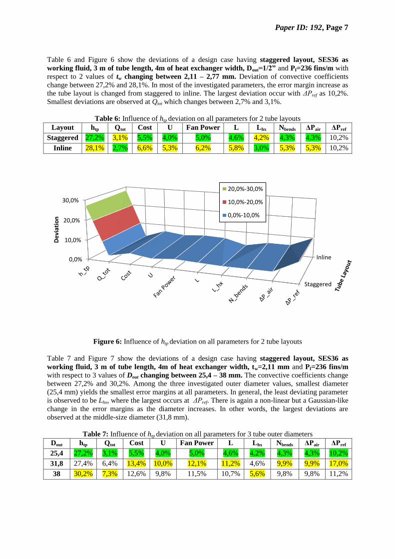
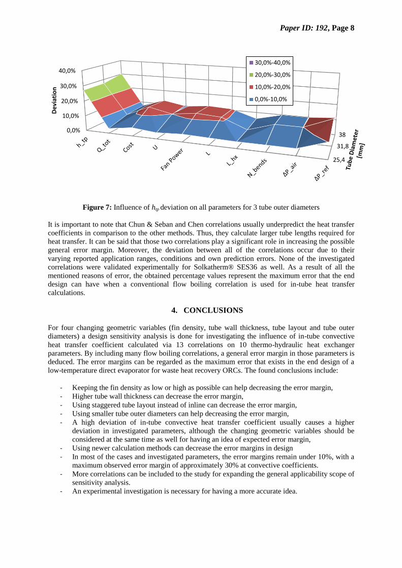
Table 7 and Figure 7 show the deviations of a design case having staggered layout, SES36 as
working fluid, 3 m of tube length, 4m of heat exchanger width, tw=2,11 mm and Pf=236 fins/m
with respect to 3 values of Dout changing between 25,4 – 38 mm. The convective coefficients change
between 27,2% and 30,2%. Among the three investigated outer diameter values, smallest diameter
(25,4 mm) yields the smallest error margins at all parameters. In general, the least deviating parameter
is observed to be Lhx, where the largest occurs at ΔPref. There is again a non-linear but a Gaussian-like
change in the error margins as the diameter increases. In other words, the largest deviations are
observed at the middle-size diameter (31,8 mm).
Table 7: Influence of htp deviation on all parameters for 3 tube outer diameters
Dout htp Qtot Cost U Fan Power L Lhx Nbends ΔPair ΔPref
25,4 27,2% 3,1% 5,5% 4,0% 5,0% 4,6% 4,2% 4,3% 4,3% 10,2%
31,8 27,4% 6,4% 13,4% 10,0% 12,1% 11,2% 4,6% 9,9% 9,9% 17,0%
38 30,2% 7,3% 12,6% 9,8% 11,5% 10,7% 5,6% 9,8% 9,8% 11,2%
Staggered
Inline0,0%
10,0%
20,0%
30,0%
De
viat
ion
20,0%-30,0%
10,0%-20,0%
0,0%-10,0%
Paper ID: 192, Page 8
Figure 7: Influence of htp deviation on all parameters for 3 tube outer diameters
It is important to note that Chun & Seban and Chen correlations usually underpredict the heat transfer
coefficients in comparison to the other methods. Thus, they calculate larger tube lengths required for
heat transfer. It can be said that those two correlations play a significant role in increasing the possible
general error margin. Moreover, the deviation between all of the correlations occur due to their
varying reported application ranges, conditions and own prediction errors. None of the investigated
correlations were validated experimentally for Solkatherm® SES36 as well. As a result of all the
mentioned reasons of error, the obtained percentage values represent the maximum error that the end
design can have when a conventional flow boiling correlation is used for in-tube heat transfer
calculations.
4. CONCLUSIONS
For four changing geometric variables (fin density, tube wall thickness, tube layout and tube outer
diameters) a design sensitivity analysis is done for investigating the influence of in-tube convective
heat transfer coefficient calculated via 13 correlations on 10 thermo-hydraulic heat exchanger
parameters. By including many flow boiling correlations, a general error margin in those parameters is
deduced. The error margins can be regarded as the maximum error that exists in the end design of a
low-temperature direct evaporator for waste heat recovery ORCs. The found conclusions include:
- Keeping the fin density as low or high as possible can help decreasing the error margin,
- Higher tube wall thickness can decrease the error margin,
- Using staggered tube layout instead of inline can decrease the error margin,
- Using smaller tube outer diameters can help decreasing the error margin,
- A high deviation of in-tube convective heat transfer coefficient usually causes a higher
deviation in investigated parameters, although the changing geometric variables should be
considered at the same time as well for having an idea of expected error margin,
- Using newer calculation methods can decrease the error margins in design
- In most of the cases and investigated parameters, the error margins remain under 10%, with a
maximum observed error margin of approximately 30% at convective coefficients.
- More correlations can be included to the study for expanding the general applicability scope of
sensitivity analysis.
- An experimental investigation is necessary for having a more accurate idea.
25,4
31,8
380,0%
10,0%
20,0%
30,0%
40,0%
De
viat
ion
30,0%-40,0%
20,0%-30,0%
10,0%-20,0%
0,0%-10,0%
Paper ID: 192, Page 9
NOMENCLATURE
A area (m²)
D diameter (mm)
G mass flux (kg/m²s)
h convective coefficient (W/m²K)
H Enthalpy (J/kg)
k thermal conductivity (W/mK)
L Length (m)
N number of (–)
P pressure, pitch (Pa, fins/m)
Pr Prandtl number (–)
Re Reynold’s number (–)
Q transferred heat (W)
t thickness (mm)
T temperature (°C)
U overall heat transfer coeff. (W/m²K)
W width (m)
Subscript
air air-side
bends U-bends
crit critical
evap evaporation
hx heat exchanger
in in-tube side
liq liquid phase
min minimum
out outer-tube side
ref refrigerant side
sat saturation
tp two-phase
tot total
Greek
ρ density (kg/m³)
Δ difference (-)
REFERENCES
Bennett, D.L., Chen, J.C., 1980, Forced convective boiling in vertical tubes for saturated pure
components and binary mixtures, AIChE Journal., vol. 26, no. 3: p. 454-461.
Chen, J.C., 1966, Correlation for boiling heat transfer to saturated fluids in convective flow, Industrial
& Engineering Chemistry Process Design and Development, vol. 5, no. 3: p. 322-329.
Chun, K.R., Seban, R.A., 1971, Heat transfer to evaporating liquid films, Journal of Heat Transfer,
vol. 93, no. 4: p. 391-396.
Dobson, M.K., Wattelet, J.P., Chato, J.C., 1993, Optimal sizing of two-phase heat exchangers, Project
Deliverable ACRC TR-42, 21 pages, Air Conditioning and Refrigeration Center. College of
Engineering. University of Illinois at Urbana-Champaign.
Fischer, J., 2011, Comparison of trilateral cycles and organic Rankine cycles, Energy, vol. 36: p.
6208-6219.
Friedel, L., 1979, Improved friction pressure drop correlations for horizontal and vertical two-phase
pipe flow, In European two-phase flow group meeting, Paper E, vol. 2: p. 1979.

Paper ID: 192, Page 10
Galvez, J.B., 2009, Publishable Executive Summary – Final Report, mechanical power generation
based on solar thermodynamic engines (POWERSOL), Project No: 032344, 42 pages
Gungor, K.E., Winterton, R.H.S., 1986, A general correlation for flow boiling in tubes and annuli,
International Journal of Heat and Mass Transfer, vol. 29, no. 3: p. 351-358.
Kandlikar, S.G., 1990, A general correlation for saturated two-phase flow boiling heat transfer inside
horizontal and vertical tubes, Journal of heat transfer, vol. 112, no. 1: p. 219-228.
Klimenko, V.V., 1988, A generalized correlation for two-phase forced flow heat transfer,
International Journal of heat and mass transfer, vol. 31, no. 3: p. 541-552.
Liu, C., He, C., Gao, H., Xu, X., Xu, J., 2012, The optimal evaporation temperature of subcritical
ORC based on second law efficiency for waste heat recovery, Entropy, vol. 14, no. 3: p. 491-
504.
Liu, Z., Winterton, R.H.S., 1991, A general correlation for saturated and subcooled flow boiling in
tubes and annuli, based on a nucleate pool boiling equation. International journal of heat and
mass transfer, vol. 34, no. 11: p. 2759-2766.
Maalouf, S., Boulawz-Ksayer, E., Clodic, D., 2012, ORC finned-tube evaporator design and system
performance optimazation, International Refrigeration and Air Conditioning Conference,
Purdue, Paper 2370, 10 pages.
Mikielewicz, D., Wajs, J., Gliński, M., Zrooga, A.B.R., 2012, Experimental investigation of dryout of
SES 36, R134a, R123 and ethanol in vertical small diameter tubes, Experimental thermal and
fluid science, vol. 44: p. 556-564.
Mikielewicz, J., 2010, Micro Heat and Power Plants Working in Organic Rankine Cycle, Polish J. of
Environ. Stud, vol, 19, no. 3: p. 499-505.
Müller-Steinhagen, H., Heck, K., 1986, A simple friction pressure drop correlation for two-phase flow
in pipes, Chemical Engineering and Processing: Process Intensification, vol. 20, no. 6: p. 297-
308.
Quoilin, S., van den Broek, M., Declaye, S., Dewallef, P., Lemort, V., 2013, Techno-economic survey
of Organic Rankine Cycle (ORC) systems, Renewable and Sustainable Energy Reviews, vol. 22:
p. 168-186.
Ribatski, G, Thome, J.R., 2007, Two-Phase Flow and Heat Transfer across Horizontal Tube Bundles‐A Review, Heat transfer engineering, vol. 28, no. 6: p. 508-524.
Riva, M., Flohr, F., Fröba, A., 2006, New fluid for high temperature applications, International
Refrigeration and Air Conditioning Conference, Purdue, Paper R106, 9 pages.
Saleh, B., Koglbauer, G., Wendland, M., Fischer, J., 2007, Working fluids for low-temperature
organic Rankine cycles, Energy, vol. 32, no. 7: p. 1210-1221.
Schlunder, E.U., 1986, Heat exchanger design handbook. Supplement 3, Taylor & Francis Inc, USA.
Shah, M.M., 1976, A new correlation for heat transfer during boiling flow through pipes, Ashrae
Trans, vol. 82, no. 2: p. 66-86.
Shengjun, Z., Huaixin, W., Tao, G., 2011, Performance comparison and parametric optimization of
subcritical Organic Rankine Cycle (ORC) and transcritical power cycle system for low-
temperature geothermal power generation, Applied Energy, vol. 88, no. 8: p. 2740-2754.
Siddiqi, M.A., Atakan, B., 2011, Investigation of the criteria for fluid selection in Rankine cycles for
waste heat recovery. International Journal of Thermodynamics, vol. 14, no. 3: p. 117-123.
Steiner, D., Taborek, J., 1992, Flow boiling heat transfer in vertical tubes correlated by an asymptotic
model. Heat transfer engineering, vol. 13, no. 2: p. 43-69.
Thome, J.R., 2004, Engineering data book III, Wolverine Tube Inc., Switzerland
VDI-Gesellschaft Verfahrenstechnik und Chemieingenieurwesen, & VDI Gesellschaft (Eds.), 2010,
VDI Heat Atlas, Springer, Germany, 1606 pages.
Related Documents