IOSR Journal of Mechanical and Civil Engineering (IOSR-JMCE) e-ISSN: 2278-1684,p-ISSN: 2320-334X, Volume 13, Issue 5 Ver. II (Sep. - Oct. 2016), PP 97-114 www.iosrjournals.org DOI: 10.9790/1684-13050297114 www.iosrjournals.org 97 | Page Design and Optimization of Straddle Carrier Trolley Gate Rajesh Kumar # , A. B. Gaikwad # # Department of Mechanical Engineering,Dr. D. Y. Patil School of engineering, Charholi(Bk), Pune- 412105, Savitribai Phule Pune University. Abstract: Straddle carriers help optimize terminal productivity by decoupling waterside and landside operations. The speed, reach and flexibility of straddle carriers allow terminals to use a single type of equipment for all container operations. Kalmar straddle carriers can handle loads of up to 60 tonnes and stack containers up to 4-high. Kalmar straddle carrier is built on a heritage of over 70 years. To date over 5000 units have been manufactured. The first fully automated terminal are using Kalmar Autostrada was open in Brisbane, Australia in 2005. Kalmar develops energy-efficient, safe and intelligent machinery and automation solutions at its Technology and Competence Centre in Tampere, Finland. The Centre is a unique research facility that simulates port operations and includes an extensive testing area for new equipment and solutions. There are different type of straddle carrier are using to handling the container on the port. In these there are different type of components are assembled in this vehicle.Here we are considering one of the important part of the straddle carrier which is called gate frame. This gate is important related to the safety for the people who are working there. Keywords: Gate design, Gate optimization, Bolt calculation, Finite element approach, experimental analysis. I. Introduction There are different type of straddle carrier are using to handling the container on the port. In these there are different type of components are assembled in this vehicle. Here we are considering one of the important parts of the straddle carrier which is called gate. This gate is important related to the safety for the people who are working there on the different platforms, 4 to 5 self- closing gates should be installed to prevent people from falling down. These gates need to withstand a force of 250 Kg both in horizontal as in vertical direction without plastic deforming. This needs to be proven by calculation notes provided by the manufacturer. The purpose of this research is to increase the load capacity of gate. For this there is requirement of modification in the shape of gate geometry. Thus gate is modified and check for the stress and vibration analysis. After doing modifications in the geometry and its iterations for the analysis, we will get the required results. As per the requirement, the simulation of a model should be done using software. For that we follow two basic steps as modeling and then analysis. We do modeling in CATIA V5 and analysis in „ANSYS'. The main part of this project is to do analysis using „ANSYS'. For this finite element analysis is required to study. The main motivation behind the work was to go for FEA of this structure. The gate structure is taken for staticanalysis.Since last decade advent of powerful finite element analysis (FEA) have proven good tool to analyses the problem. The Various complicated geometries can be analyzed by FEAinstead of doing analytical calculations. Optimized meshing and accurate simulation of boundary conditions along with the ability to apply complex load, provided by various FEM packages have helped the designer to carry vibration analysis with the investigation of critical stresses and contact stresses. FEM is used to find critical locations and quantitative analysis of stress distribution and deformed shape under loads. However detailed modeling and specialized knowledge of FEM theory are indispensable to perform these analyses with high accuracy. They also require complicated meshing strategies. Simulations of actual boundary conditions to equivalent FE boundary conditions have to be done carefully because a wrongly modeled boundary condition leads to erroneous results. The solution of such large scale FEM problem requires both large memory and disc space as computing resources. II. Literature Review Self-closing gate is used in the straddle carrier. It is used for the safety purpose of operator. This product is under the Cargotec Company. They have developed the process of this gate structure. But the initially load carrying capacity was less for the structure. Hence company needs to increase the load capacity of the gate structure [1]. Americannational standard (ANSI/ASSE Z359.14-2014) safety requirements for self-retracting devices for personal fall arrest & Rescue System. This standard establishes requirements for SRDs intended for use in personal fall arrest or rescue systems for authorized persons within the capacity range of 59 to 141 kg.[2]

Welcome message from author
This document is posted to help you gain knowledge. Please leave a comment to let me know what you think about it! Share it to your friends and learn new things together.
Transcript

IOSR Journal of Mechanical and Civil Engineering (IOSR-JMCE)
e-ISSN: 2278-1684,p-ISSN: 2320-334X, Volume 13, Issue 5 Ver. II (Sep. - Oct. 2016), PP 97-114
www.iosrjournals.org
DOI: 10.9790/1684-13050297114 www.iosrjournals.org 97 | Page
Design and Optimization of Straddle Carrier Trolley Gate
Rajesh Kumar#, A. B. Gaikwad
#
#Department of Mechanical Engineering,Dr. D. Y. Patil School of engineering, Charholi(Bk), Pune-
412105, Savitribai Phule Pune University.
Abstract: Straddle carriers help optimize terminal productivity by decoupling waterside and landside
operations. The speed, reach and flexibility of straddle carriers allow terminals to use a single type of
equipment for all container operations. Kalmar straddle carriers can handle loads of up to 60 tonnes and stack
containers up to 4-high. Kalmar straddle carrier is built on a heritage of over 70 years. To date over 5000 units
have been manufactured. The first fully automated terminal are using Kalmar Autostrada was open in Brisbane,
Australia in 2005. Kalmar develops energy-efficient, safe and intelligent machinery and automation solutions at
its Technology and Competence Centre in Tampere, Finland. The Centre is a unique research facility that
simulates port operations and includes an extensive testing area for new equipment and solutions. There are
different type of straddle carrier are using to handling the container on the port. In these there are different type
of components are assembled in this vehicle.Here we are considering one of the important part of the straddle
carrier which is called gate frame. This gate is important related to the safety for the people who are working
there.
Keywords: Gate design, Gate optimization, Bolt calculation, Finite element approach, experimental analysis.
I. Introduction There are different type of straddle carrier are using to handling the container on the port. In these there
are different type of components are assembled in this vehicle.
Here we are considering one of the important parts of the straddle carrier which is called gate. This gate
is important related to the safety for the people who are working there on the different platforms, 4 to 5 self-
closing gates should be installed to prevent people from falling down. These gates need to withstand a force of
250 Kg both in horizontal as in vertical direction without plastic deforming. This needs to be proven by
calculation notes provided by the manufacturer.
The purpose of this research is to increase the load capacity of gate. For this there is requirement of
modification in the shape of gate geometry. Thus gate is modified and check for the stress and vibration
analysis. After doing modifications in the geometry and its iterations for the analysis, we will get the required
results. As per the requirement, the simulation of a model should be done using software. For that we follow two
basic steps as modeling and then analysis. We do modeling in CATIA V5 and analysis in „ANSYS'. The main
part of this project is to do analysis using „ANSYS'. For this finite element analysis is required to study. The
main motivation behind the work was to go for FEA of this structure. The gate structure is taken for
staticanalysis.Since last decade advent of powerful finite element analysis (FEA) have proven good tool to
analyses the problem. The Various complicated geometries can be analyzed by FEAinstead of doing analytical
calculations. Optimized meshing and accurate simulation of boundary conditions along with the ability to apply
complex load, provided by various FEM packages have helped the designer to carry vibration analysis with the
investigation of critical stresses and contact stresses. FEM is used to find critical locations and quantitative
analysis of stress distribution and deformed shape under loads. However detailed modeling and specialized
knowledge of FEM theory are indispensable to perform these analyses with high accuracy. They also require
complicated meshing strategies. Simulations of actual boundary conditions to equivalent FE boundary
conditions have to be done carefully because a wrongly modeled boundary condition leads to erroneous results.
The solution of such large scale FEM problem requires both large memory and disc space as computing
resources.
II. Literature Review Self-closing gate is used in the straddle carrier. It is used for the safety purpose of operator. This
product is under the Cargotec Company. They have developed the process of this gate structure. But the initially
load carrying capacity was less for the structure. Hence company needs to increase the load capacity of the gate
structure [1].
Americannational standard (ANSI/ASSE Z359.14-2014) safety requirements for self-retracting devices
for personal fall arrest & Rescue System. This standard establishes requirements for SRDs intended for use in
personal fall arrest or rescue systems for authorized persons within the capacity range of 59 to 141 kg.[2]

Design and Optimization of Straddle Carrier Trolley Gate
DOI: 10.9790/1684-13050297114 www.iosrjournals.org 98 | Page
American national standard (ANSI/ASSE Z359.4-2013) safety requirements for assisted-rescue,
subsystems and components. Establishes requirements for the performance, design,marking, qualification,
instruction, training, use, maintenance and removal from service of connectors, harnesses, lanyards, anchorage
connectors, winches/hoists, descent control devices [3]
III. Problem Statement And Objective Design and optimization of self-closing gate for straddle carrier and improving the strength of gate and
provide safety to the operator”. The Existing gate was not able to provide the strength for safety of operator .The
straddle Carrier Company has decided to change the design with analysis of safety gate. Now for new design of
gate they increase the load capacity of the gate. Now the gate is designed in a category of self-closing gate. For
this project we will consider different type of arrangements for the gate installation like bolted arrangement or
bearing arrangement.
IV. Theoretical Calculation
A. The dimensions of gate structure
Table IDimensions of Gate
Properties Dimensions
Outer diameter of a circular pipe 33.7 mm
Inner diameter of a circular pipe 28.5 mm
Thickness 2.6 mm
Dimension of rectangular pipe 40*34 mm
Thickness of rectangular pipe 3 mm
Bolt size M16
Maximum vertical load (P) 2500 N
B .The material properties of steel
The material used for this structure is steel S235 JR.
Table IIMaterial Properties Material S235JR
Young‟s modulus 2.1e5MPa
Poisson‟s ratio 0.3
Density 7.850×10⁻³ tons/mm3.
Yield strength 355MPa
So, first we have to find out deflection forexisting and modifiedGate model.
C. Deflection of existing gate model
The basic principal point for this structure is to decrease the permanent deflection. For this these are
following terms and calculation process to calculate the deflection.
Let,
O.D of circular pipe = 33.7 mm
I.D of circular pipe = 28.5 mm
Thickness of pipe(T) = 2.6 mm
Pipe effective length in horizontal direction = 400 mm
Pipe effective length in vertical direction = 300 mm
For circular hollow cross section:
I (Area moment of inertia) = π/64[(D4)-(d
4)]
= .05 [(33.74)-(28.5
4)]
= 30927 mm4
Stiffness in X direction = Kx = K1, K3
Stiffness in Y direction = Ky = K2
Kx = (3×EI)/L3
= (3×210000×30927)/4003
= 304.44 Nmm
Ky = AE/L
= (254×210000)/300
= 177820.4 Nmm
K12 = (1/k1)+(1/k2)
= [(K1+K2)/K1×K2]
= [(304.44+177820.4)/(304.44×177820.4)]
Design and Optimization of Straddle Carrier Trolley Gate
DOI: 10.9790/1684-13050297114 www.iosrjournals.org 99 | Page
= 303.9 Nmm
K123 = K3 +K12
= 304.44+303.9
= 608.35 Nmm
K equivalent = K123
K equivalent = 608.35 Nmm
Deflection (δ) = Force/ Stiffness
= 2500/608.35
Deflection (δ) = 4.109 mm
D. Deflection of modified gate model
The basic principal point for this structure is to decrease the permanent deflection. For this these are
following terms and calculation process to calculate the deflection.
Let,
O.D of circular pipe = 33.7 mm
I.D of circular pipe = 28.5 mm
Thickness of pipe(T) = 2.6 mm
Pipe effective length in horizontal direction = 400 mm
Pipe effective length in vertical direction = 300 mm
For circular hollow cross section:
I(Area moment of inertia) = π/64[(D4)-(d
4)]
= (.05) [(33.74)-(28.5
4)]
= 30927 mm4
Stiffness of the structure ( K):
Stiffness in X direction= Kx = K1, K3& K5
Stiffness in Y direction= Ky = K2& K4
Kx = (3*EI)/L3
= (3*210000*30927)/4003
= 304.44Nmm
Ky = AE/L
= (254*210000)/300
= 177820.4 Nmm
K12= (1/k1)+(1/k2)
= [(K1+K2)/K1.K2]
= [(304.44+177820.4)/304.44*177820.4]
=303.9Nmm
K123= K3 +K12
= 304.44+303.9
= 608.35 Nmm
K14= [(1/K123)+(1/K4)]
= [(K4+K123)/K4*K123]
= [(177820.4+608.35)/(177820.4*608.35)]
= 606.3Nmm
K equivalent = K5+K14
= 304.44+606.3
= 910.7Nmm
Deflection(δ) = Force/ Stiffness
= 2500/910.7
= 2.745 mm
Design and Optimization of Straddle Carrier Trolley Gate
DOI: 10.9790/1684-13050297114 www.iosrjournals.org 100 | Page
E. Stress criteria:
Sut = Ultimate tensile strength of material
=510 Mpa
Su= Yield strength of material N/mm2
= 355Mpa
Sy= Working yield strength of material N/mm2
= 235Mpa
Fos (Factor of safety) = [Su/Sy]
= (355/235)
= 1.5
F. Natural frequency of structure:
K= Equivalent stiffness of structure= 910.7 Nmm
M= Mass of the structure = 10 kg
K = 91037N/mm
ωn = K
m
ωn= 910.7
10
ωn = 91.07 rad/sec
𝑓𝑛=
𝜔𝑛
2𝜋
𝒇𝒏 = 𝟐. 𝟎 𝑯𝒛
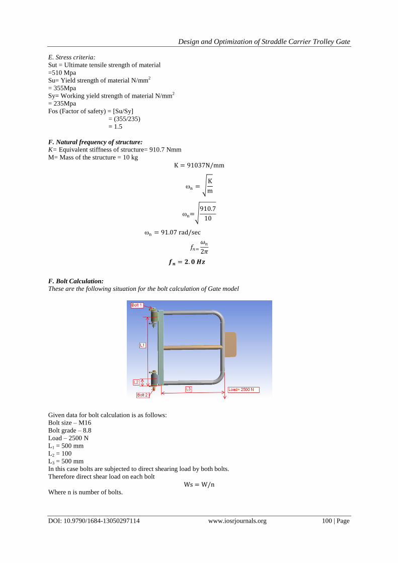
F. Bolt Calculation:
These are the following situation for the bolt calculation of Gate model
Given data for bolt calculation is as follows:
Bolt size – M16
Bolt grade – 8.8
Load – 2500 N
L1 = 500 mm
L2 = 100
L3 = 500 mm
In this case bolts are subjected to direct shearing load by both bolts.
Therefore direct shear load on each bolt
Ws = W/n
Where n is number of bolts.
Design and Optimization of Straddle Carrier Trolley Gate
DOI: 10.9790/1684-13050297114 www.iosrjournals.org 101 | Page
Ws = 0.25 × 1000 ×9.81
2
= 12262.5 N
= 12.26 KN
Each bolt will experience a different load which also depends up on the distance from the extreme load distance
Let W be the load in a bolt per unit distance due to the turning effect of bracket and W1 and W2 be the loads on
both bolt at distance L1 and L2
Load on each bolt at distance L1
W1 = w×L1
And moment of this load about extreme length
M1 = w×L1×L1
M1 = w× (L1)2
Similarly,
M2 = w× (L2)2
Hence total moment of the load on the bolts about extreme length
M = 4w (L1)2 + 4w (L2)
2
Also the moment due to the load 2500 N about extreme length
M = W×L
From equation (3.16) and (3.17)
W×L = w× (L1)2+w× (L2)
2
w = (W×L)/4[(L1)2+ (L2)
2
w = (0.25×1000×9.81×500)/ [(500)2+ (100)2]
= 4.80 N/mm
It may be noted that the most heavily loaded bolts are those which are situated at the greatest distance from
tilting edge. In this case, the bolts at distance L1 are heavily loaded
Hence, tensile load on each bolt at distance L1
Wt1 = w×L1
= 4.80×500
= 2400 N
= 2.4 KN
Since the bolts are subjected to shear load and tensile load therefore
Equivalent tensile load,
Wte = 1/2[Wt + √[ Wt2 + 4 Ws2 ] = 1/2[2.4+√ [(2.42) +4(12.262)]
= 13.518 KN
Here equivalent tensile load = 13.518 KN
For M16 bolt, Stress area is 157 mm2
Therefore,
Equivalent tensile stress =
Ϭteqv= (13.518×1000)/157
= 86 MPa
Equivalent shear load,
Wte = 1/2[√[ Wt2 + 4 Ws2 ] = 1/2[√ [(2.42) +4(12.262)]
= 12.32 KN
Here equivalent shear load = 12.32 KN
Equivalent shear stress =
Ϭseqv= (12.32*1000)/157
= 78 MPa

Design and Optimization of Straddle Carrier Trolley Gate
DOI: 10.9790/1684-13050297114 www.iosrjournals.org 102 | Page
Comparison of bolt calculation has been done in next chapter Finite Element Analysis.
Design and Optimization of Straddle Carrier Trolley Gate
DOI: 10.9790/1684-13050297114 www.iosrjournals.org 103 | Page
V. Finite Element Analysis
Static stress analysis of gate of straddle carrier is performed by ANSYS 16.1 software to determine the
stress and deflection values of both Existing and Modified structure.
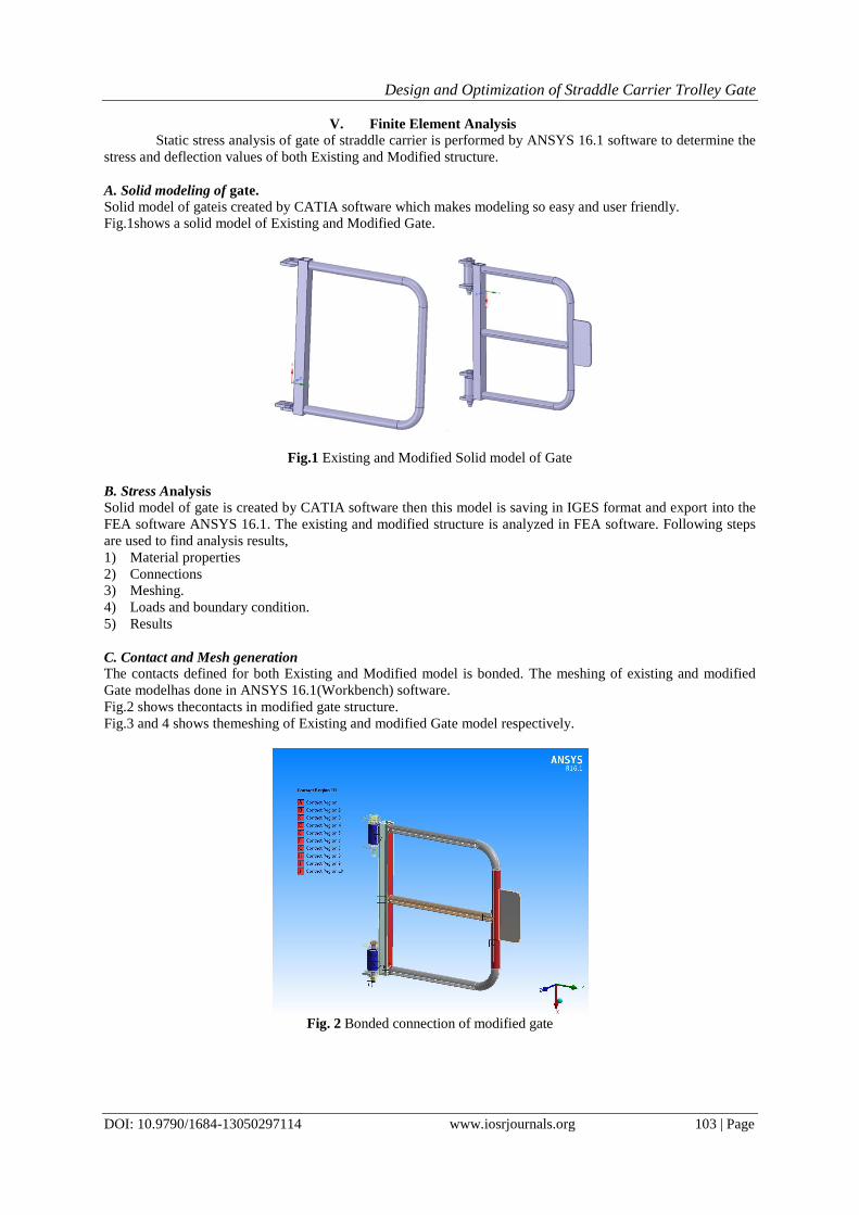
A. Solid modeling of gate.
Solid model of gateis created by CATIA software which makes modeling so easy and user friendly.
Fig.1shows a solid model of Existing and Modified Gate.
Fig.1 Existing and Modified Solid model of Gate
B. Stress Analysis
Solid model of gate is created by CATIA software then this model is saving in IGES format and export into the
FEA software ANSYS 16.1. The existing and modified structure is analyzed in FEA software. Following steps
are used to find analysis results,
1) Material properties
2) Connections
3) Meshing.
4) Loads and boundary condition.
5) Results
C. Contact and Mesh generation
The contacts defined for both Existing and Modified model is bonded. The meshing of existing and modified
Gate modelhas done in ANSYS 16.1(Workbench) software.
Fig.2 shows thecontacts in modified gate structure.
Fig.3 and 4 shows themeshing of Existing and modified Gate model respectively.
Fig. 2 Bonded connection of modified gate

Design and Optimization of Straddle Carrier Trolley Gate
DOI: 10.9790/1684-13050297114 www.iosrjournals.org 104 | Page
Fig. 3 meshing of existing gate
Fig. 4 meshing of modified gate
D. Loads and Boundary Conditions
Static structural analysis was performed to determine equivalent (von-misses) stresses and total
deformation of existing and modified Gate model by ANSYS software. For this above boundary conditions are

Design and Optimization of Straddle Carrier Trolley Gate
DOI: 10.9790/1684-13050297114 www.iosrjournals.org 105 | Page
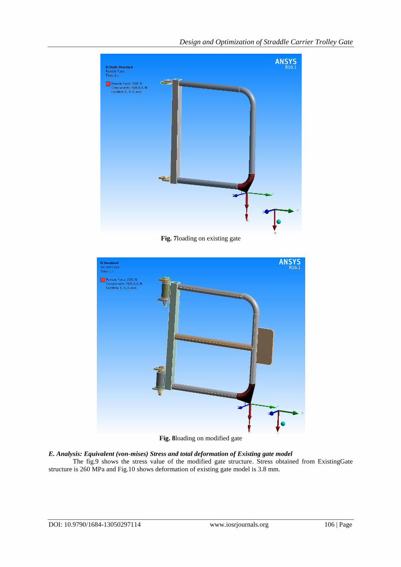
used: Fixed support and Force. Existing and modified Gate model is fixed as shown in fig.7 and fig.8 Maximum
load is 2500N. So, 2500N load was applied on vertical direction of structure in downward direction.
Fig. 5 Fixed supports for Existinggate
Fig. 6 Fixed supports for Modified Gate
Design and Optimization of Straddle Carrier Trolley Gate
DOI: 10.9790/1684-13050297114 www.iosrjournals.org 106 | Page
Fig. 7loading on existing gate
Fig. 8loading on modified gate
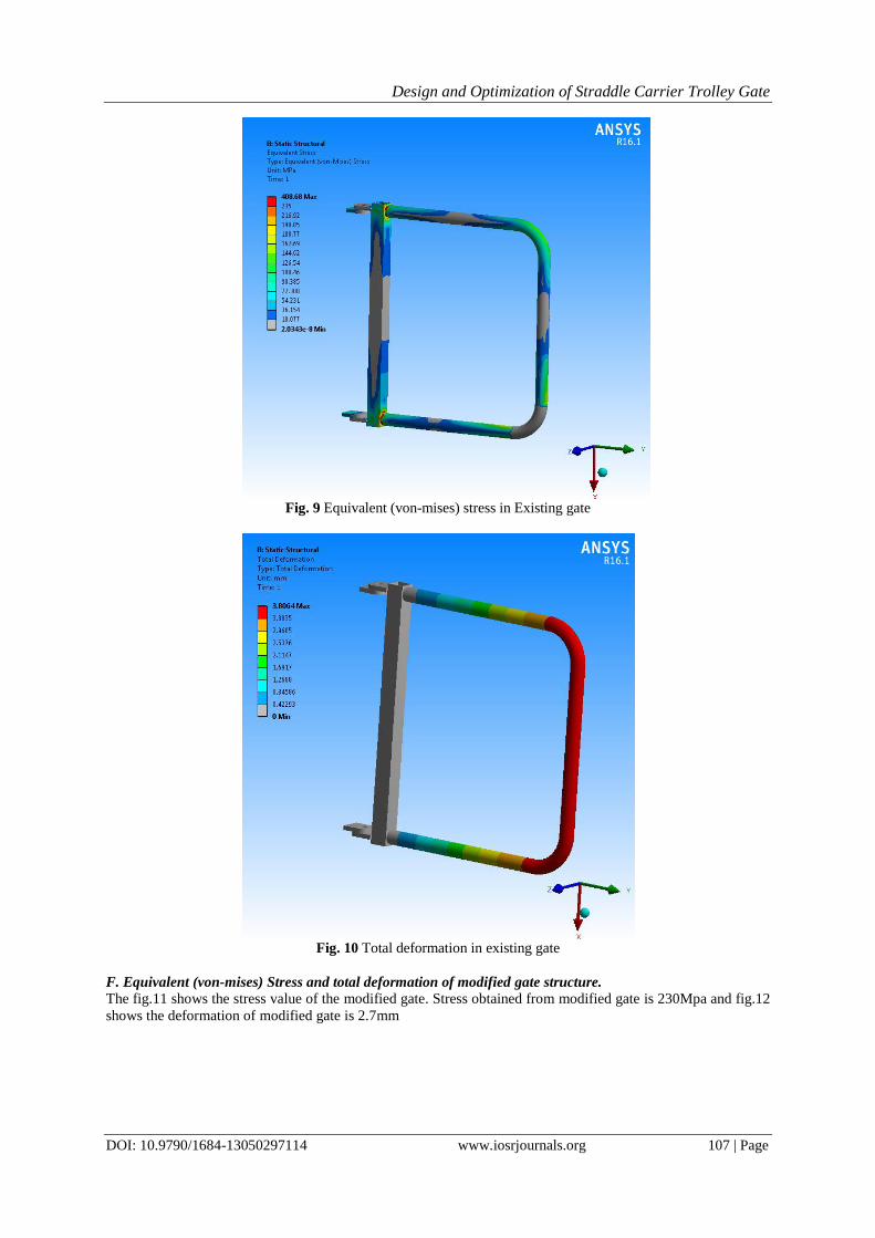
E. Analysis: Equivalent (von-mises) Stress and total deformation of Existing gate model
The fig.9 shows the stress value of the modified gate structure. Stress obtained from ExistingGate
structure is 260 MPa and Fig.10 shows deformation of existing gate model is 3.8 mm.
Design and Optimization of Straddle Carrier Trolley Gate
DOI: 10.9790/1684-13050297114 www.iosrjournals.org 107 | Page
Fig. 9 Equivalent (von-mises) stress in Existing gate
Fig. 10 Total deformation in existing gate
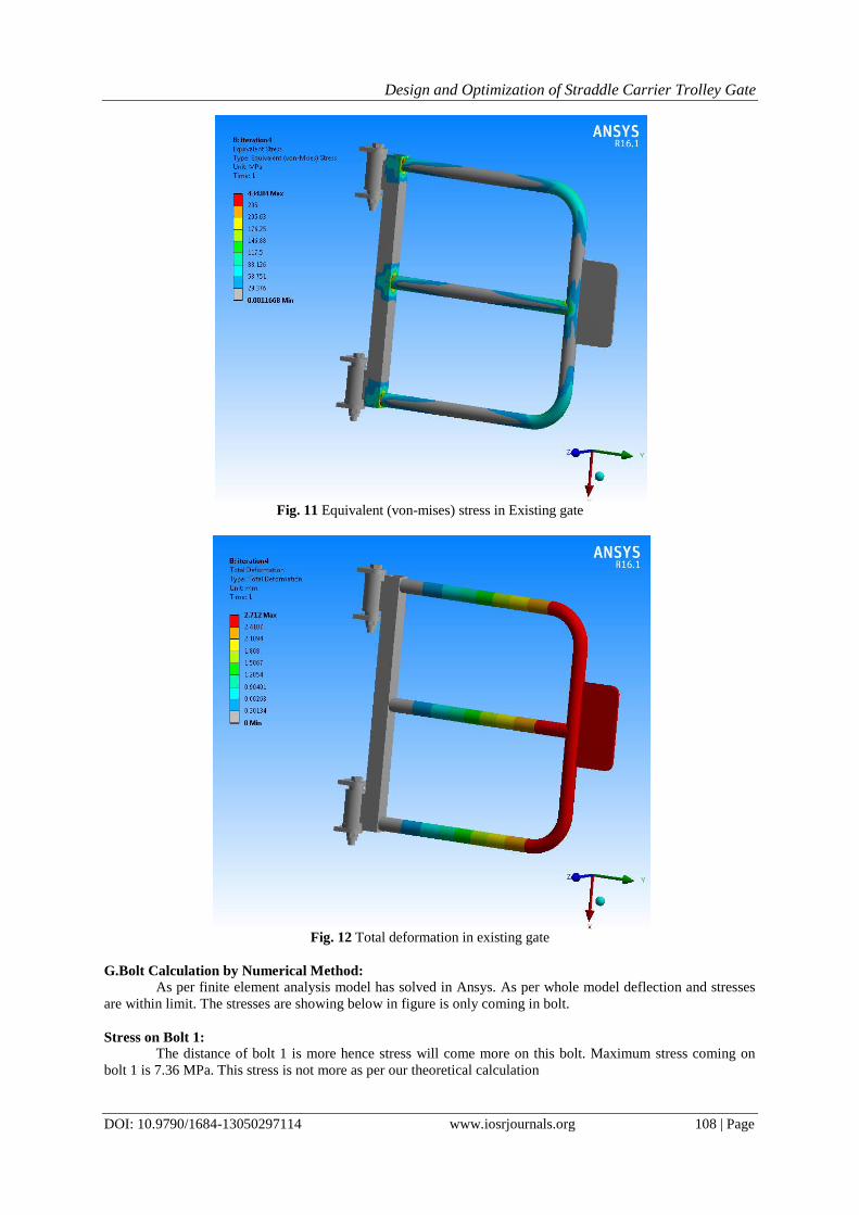
F. Equivalent (von-mises) Stress and total deformation of modified gate structure.
The fig.11 shows the stress value of the modified gate. Stress obtained from modified gate is 230Mpa and fig.12
shows the deformation of modified gate is 2.7mm
Design and Optimization of Straddle Carrier Trolley Gate
DOI: 10.9790/1684-13050297114 www.iosrjournals.org 108 | Page
Fig. 11 Equivalent (von-mises) stress in Existing gate
Fig. 12 Total deformation in existing gate
G.Bolt Calculation by Numerical Method:
As per finite element analysis model has solved in Ansys. As per whole model deflection and stresses
are within limit. The stresses are showing below in figure is only coming in bolt.
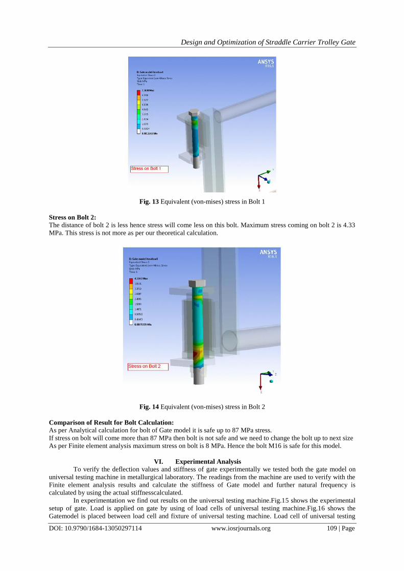
Stress on Bolt 1:
The distance of bolt 1 is more hence stress will come more on this bolt. Maximum stress coming on
bolt 1 is 7.36 MPa. This stress is not more as per our theoretical calculation
Design and Optimization of Straddle Carrier Trolley Gate
DOI: 10.9790/1684-13050297114 www.iosrjournals.org 109 | Page
Fig. 13 Equivalent (von-mises) stress in Bolt 1
Stress on Bolt 2:
The distance of bolt 2 is less hence stress will come less on this bolt. Maximum stress coming on bolt 2 is 4.33
MPa. This stress is not more as per our theoretical calculation.
Fig. 14 Equivalent (von-mises) stress in Bolt 2
Comparison of Result for Bolt Calculation:
As per Analytical calculation for bolt of Gate model it is safe up to 87 MPa stress.
If stress on bolt will come more than 87 MPa then bolt is not safe and we need to change the bolt up to next size
As per Finite element analysis maximum stress on bolt is 8 MPa. Hence the bolt M16 is safe for this model.
VI. Experimental Analysis
To verify the deflection values and stiffness of gate experimentally we tested both the gate model on
universal testing machine in metallurgical laboratory. The readings from the machine are used to verify with the
Finite element analysis results and calculate the stiffness of Gate model and further natural frequency is
calculated by using the actual stiffnesscalculated.
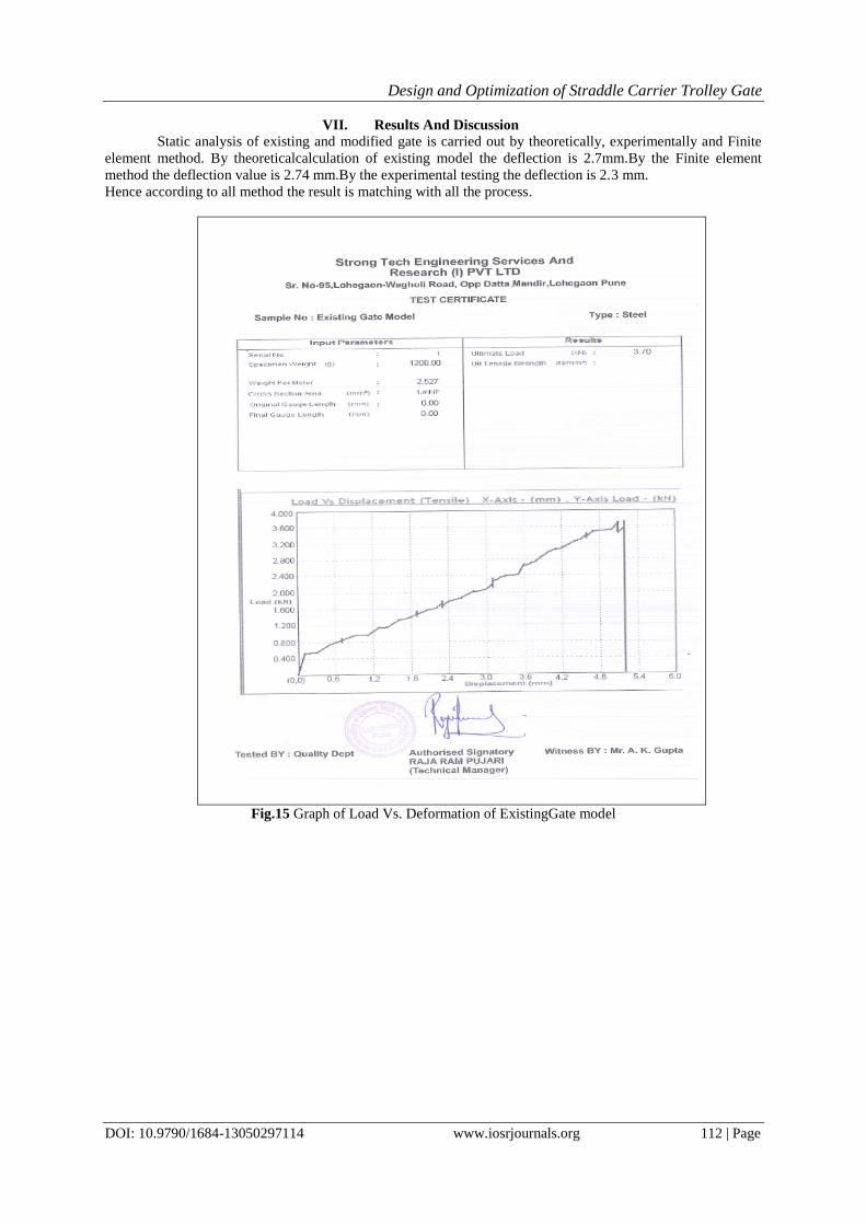
In experimentation we find out results on the universal testing machine.Fig.15 shows the experimental
setup of gate. Load is applied on gate by using of load cells of universal testing machine.Fig.16 shows the
Gatemodel is placed between load cell and fixture of universal testing machine. Load cell of universal testing

Design and Optimization of Straddle Carrier Trolley Gate
DOI: 10.9790/1684-13050297114 www.iosrjournals.org 110 | Page
machine is 2500N.Load limit is set on the computer also put cross sectional area of gate model to find out the
stresses on the peak load. As the load apply on the gate the display of universal testing machine shows the graph
of load vs. deformation.
By using this we can find out the deflection of gate at deformation point. We take peak load value for
both gate model and take deflection value on that peak load.Deflection values for the Existing gate are 3.6 mm
and Modified Gate model is 2.3 mm.
Fig. 15 Experimental setup
Fig.16Loading on gate by load cell.

Design and Optimization of Straddle Carrier Trolley Gate
DOI: 10.9790/1684-13050297114 www.iosrjournals.org 111 | Page
Fig 17: Adjustment of model in the UTM
The deflection value is taken at peak load and this value is compare with our FEA and theoretical
results also calculate stiffness for both gates from load vs. Deformation graph. By using stiffness we find out the
natural frequency of both model and frequencies of both structure is in the range. Same procedure was applied
for both gate models.
A.Experimental results
From experimentation, we obtain graph of load Vs. deformation of both gate on that graph we also get
the peak load value and stress on that load. So this stress was used to analized the results.Fig.11 & 12 shows the
graph of load Vs. deformation of Existing and modifiedGate model is respectively. On X axis it shows the
deflection(mm) values and Y axis it shows the load (KN) of Gate.
Design and Optimization of Straddle Carrier Trolley Gate
DOI: 10.9790/1684-13050297114 www.iosrjournals.org 112 | Page
VII. Results And Discussion
Static analysis of existing and modified gate is carried out by theoretically, experimentally and Finite
element method. By theoreticalcalculation of existing model the deflection is 2.7mm.By the Finite element
method the deflection value is 2.74 mm.By the experimental testing the deflection is 2.3 mm.
Hence according to all method the result is matching with all the process.
Fig.15 Graph of Load Vs. Deformation of ExistingGate model

Design and Optimization of Straddle Carrier Trolley Gate
DOI: 10.9790/1684-13050297114 www.iosrjournals.org 113 | Page
Fig.16 Graph of Load Vs. Deformation of ModifiedGate.
Allowable stress = Yield strength / Factor of safety
= 355/1.5
= 235 MPa
So, the calculated stress < allowable stress. i.e. 230 MP, our design of modified gate is proved to be safe.
By using FEA method stress values of Existing and modified gate are 260MPaand 230 MPa.These values also
are in the range. Experimental analysis is also shows the stress values are in range.
Table III Result Analysis Result Analysis between Existing & Modified gate
Sr.No Type of analysis Existing gate Modified gate
Theoretical Calculation (For Load-2500N)
2 Total deformation 2.745 mm 4.1 mm
FEA Analysis using ANSYS (For Load-2500N)
1 static stress 230MPa 260 MPa
2 Total deformation 2.7 mm 3.8 mm
Experimental analysis (Peak load from UTM, For existing and modified modelis 2500 N)
2. Total deformation 2.3 mm 3.6 mm
Table: Comparison of Deflection Result Sr. No.
Approach
Deflection (mm)
Existing Modified
1 FEA 3.8 2.69
2 Theoretical 4.1 2.74
3 Experimental 3.6 2.3
% Error
4 Theoretical and Experimental 8.1% 16.0%
5 FEA and Experimental 10.5% 14.5%
6 Theoretical and FEA 2.6% 1.82%

Design and Optimization of Straddle Carrier Trolley Gate
DOI: 10.9790/1684-13050297114 www.iosrjournals.org 114 | Page
VIII. Conclusion
As deflection and stress of modified gate model is within the range. Thus, the modified design is safe.
This will provide more safety for operators.
There are following important conclusion for this project.
1. As per all the three method of calculation modified model is safe. It will prevent permanent deflection of
gate.
2. Load carrying capacity of Modified model is now 250 kg.In comparison with Existing model 40% load
carrying capacity is increased.
3. According to bolt calculation bolt M16 is safe for this model.
4. As per weight comparison, Modified model weight is increase by 20% with respect to Existing model.
5. This is industry project hence they will consider all the iteration done in project and take final decision.
Acknowledgment I take this opportunity to thanks Prof A. B. Gaikwad and Prof. A. N. Patil for valuable guidance and for
providing all the necessary facilities, which were indispensable in completion of this work.
References [1]. SVENSK STANDARD SS-EN 13001-3-1:2012_1 [2]. ANSYS user manual 16.1.
[3]. American national standard (ANSI/ASSE Z359.14-2014) Safety Requirements.
[4]. Port technology reference. [5]. Dr.Sadhu Singh.(2011). Theory of Elasticity, 6th ed.Sudha Publication, India.
[6]. S. Ramamurtham, “Strength of Materials”14th Edition, DhanpatRaiPublishingCompany (P) Limited, 2012.
[7]. V. B. Bhandari, “Design of Machine Elements” Third Edition, Tata McGraw-Hill Education, 2010. [8]. A textbook of machine design by P.C.Sharma and D.K.Agarwal, S.K.Kataria and sons, 1998.
[9]. Mechanical engineering design by Joseph E. Shigley, McGraw Hill, 1986.
[10]. A Text Book Of Machine Design, R. S. Khurmi and J. K. Gupta, S. Chand and Co. Ltd.,2005Design Data Hand Book, K. Mahadevan and K. Balaveera Reddy, 3rd Edition.
[11]. Faculty of Mechanical Engineering, "Design Data Book Of Engineers", KalaikathirAchchagam, 2011, 7.110-7.(Book).
Related Documents