IOSR Journal of Mechanical and Civil Engineering (IOSR-JMCE) e-ISSN: 2278-1684,p-ISSN: 2320-334X, Volume 9, Issue 2 (Sep. - Oct. 2013), PP 15-21 www.iosrjournals.org www.iosrjournals.org 15 | Page Design and Optimization of Forged aluminium Tension strut *M. Rachel Roshiny, **K. Devaki Devi, *(Department of Mechanical Engineering, G Pulla Reddy Engineering College, Kurnool, A.P., India,) **(Department of Mechanical Engineering, G Pulla Reddy Engineering College, Kurnool, A.P., India,) Abstract: Suspension system of an automobile plays an important role in ensuring the stability of the automobile. Although it has been achieved to a considerable extent, another major aspect of suspension system is passenger car. Now a day in automobile Industries every supplier is trying to give a good product with cheap price to the customer. By considering the customer requirement I am designing Forged aluminium Tension Strut which will satisfy the customer requirement. Tension Strut is the part of Linkages system which is link between the Chassis and Wheel assembly with specific ball joint at one side and Bushing at another side. In SUV (sport utility vehicle) the strength requirement of tension strut is always in higher demand and shape should not be more bulge. Due to this requirement most of the suppliers are prefer to use “Steel” material for forged tension strut. In this project I am designing the Tension strut in 3D software Catia V-5 by providing the different types of shapes or Sections and will optimize the 3D model in FEA by applying the aluminium material for Static Load cases.FEA in V-5 will give 90% - 95% accuracy of result but it will take very less time as compare to other FEA software. For FEA(Finite Element analysis) we are having option to do in V-5 using GPS licence. For use of GPS we need to consider Boundary condition at bushing and ball joint. We need to check 3D model for manufacturing feasibility i.e. minimum draft angle and radius for forging process in V-5 before doing analysis. We will get the final optimized model in good shape or geometry with lighter in weight and also will be having a higher strength per customer requirement. Weight reduction of components in car plays a major role which may affect for cost reduction of car also. Keyword: Aluminium forging,CAD-Catia V-5,Finite Element Analysis-Catia V-5. I. Introduction Suspension system is the assembly of spring, Shock absorbers and linkages that will connect a vehicle body to wheel and then it will allow the relative motion between them. Linkages are most important to make the Fig.(a) Connection between wheel and the car body, in linkages control arm assembly, Tie rod assembly and tension strut assembly is having their different function and these are having different ball joints which is connected to Knuckle. Tie rod assembly will help to turn the wheel left and right, Control arm assembly control the change of camber angle and maintain the distance between wheel and body. Tension strut plays the same role and also help for TOE moment of the wheel in front axle. In tension strut assembly rubber or hydraulic bushing will use to link the tension strut with body and steel ball bin will use to make a spherical ball joint and it will link with knuckle.The above Fig.(a) shows the some components found in individual suspension system of front wheel. Index Explanation 1 Spring strut 2 Transverse control arm, top 3 Swivel bearing 4 Wheel bearing 5 5 Stabilizer link 6 Transverse control arm, bottom 7 Stabilizer bar 8 Tension strut with hydraulic mount 9 Front suspension, sub frame

Design and Optimization of Forged aluminium Tension strut
Jul 13, 2015
Welcome message from author
This document is posted to help you gain knowledge. Please leave a comment to let me know what you think about it! Share it to your friends and learn new things together.
Transcript

IOSR Journal of Mechanical and Civil Engineering (IOSR-JMCE)
e-ISSN: 2278-1684,p-ISSN: 2320-334X, Volume 9, Issue 2 (Sep. - Oct. 2013), PP 15-21 www.iosrjournals.org
www.iosrjournals.org 15 | Page
Design and Optimization of Forged aluminium Tension strut
*M. Rachel Roshiny, **K. Devaki Devi, *(Department of Mechanical Engineering, G Pulla Reddy Engineering College, Kurnool, A.P., India,)
**(Department of Mechanical Engineering, G Pulla Reddy Engineering College, Kurnool, A.P., India,)
Abstract: Suspension system of an automobile plays an important role in ensuring the stability of the
automobile. Although it has been achieved to a considerable extent, another major aspect of suspension system
is passenger car. Now a day in automobile Industries every supplier is trying to give a good product with cheap
price to the customer. By considering the customer requirement I am designing Forged aluminium Tension Strut which will satisfy the customer requirement. Tension Strut is the part of Linkages system which is link between
the Chassis and Wheel assembly with specific ball joint at one side and Bushing at another side. In SUV (sport
utility vehicle) the strength requirement of tension strut is always in higher demand and shape should not be
more bulge. Due to this requirement most of the suppliers are prefer to use “Steel” material for forged tension
strut. In this project I am designing the Tension strut in 3D software Catia V-5 by providing the different types of
shapes or Sections and will optimize the 3D model in FEA by applying the aluminium material for Static Load
cases.FEA in V-5 will give 90% - 95% accuracy of result but it will take very less time as compare to other FEA
software. For FEA(Finite Element analysis) we are having option to do in V-5 using GPS licence. For use of
GPS we need to consider Boundary condition at bushing and ball joint. We need to check 3D model for
manufacturing feasibility i.e. minimum draft angle and radius for forging process in V-5 before doing analysis. We will get the final optimized model in good shape or geometry with lighter in weight and also will be having a
higher strength per customer requirement. Weight reduction of components in car plays a major role which may
affect for cost reduction of car also.
Keyword: Aluminium forging,CAD-Catia V-5,Finite Element Analysis-Catia V-5.
I. Introduction Suspension system is the assembly of spring, Shock absorbers and linkages that will connect a vehicle
body to wheel and then it will allow the relative motion between them. Linkages are most important to make the
Fig.(a)
Connection between wheel and the car body, in linkages control arm assembly, Tie rod assembly and tension
strut assembly is having their different function and these are having different ball joints which is connected to
Knuckle. Tie rod assembly will help to turn the wheel left and right, Control arm assembly control the change of
camber angle and maintain the distance between wheel and body. Tension strut plays the same role and also help
for TOE moment of the wheel in front axle.
In tension strut assembly rubber or hydraulic bushing will use to link the tension strut with body and
steel ball bin will use to make a spherical ball joint and it will link with knuckle.The above Fig.(a) shows the
some components found in individual suspension system of front wheel.
Index Explanation
1 Spring strut
2 Transverse control arm, top
3 Swivel bearing
4 Wheel bearing
5 5 Stabilizer link
6 Transverse control arm, bottom
7 Stabilizer bar
8 Tension strut with hydraulic
mount
9 Front suspension, sub frame

Design and Optimization of Forged aluminium Tension strut
www.iosrjournals.org 16 | Page
1.1 TENSION STRUT:- The tension strut prevents torsion movement of the LCA. Its alignment usage is fairly important, it
maintains or changes toe.
II. Objective To design and optimize the forged aluminium tension strut by creating the 3D parametric model in 3D
software Catia V-5 and optimized the model for static analysis using Simulation and analysis module in
software Catia V-5.and also we will do the draft analysis in Catia V-5 for manufacturing feasibility of tension
strut.
III. Software Overview
a. Catia :-In catia we can use below modules for the design of Tension Strut.
3.1.1) Part Modelling:- for Solid feature.
This is the Default Workbench for creating 3D Model in V-5.
3.1.2) Generative shape design:- For Surface feature.
This workbench is used to create Line, Points and surfaces.
3.1.3) Analysis and Simulation:- To initiate FEA Calculation
To work in this module we need to select GPS licence in Catia V-5.It is useful to do FEA of Tension Strut. For Static case analysis and frequency analysis. Calculation to be done in pressure direction.
b. Design Consideration And Fea Requirement:- a) Minimum Forging radius:- 3mm.
b) Minimum Draft angle:- 3Degree.
c) Minimum Weight after Optimization .
d) FEA requirement for static:-
d.1). Material;-Aluminium Material
d.2). First Yield Force above 30kN.
d.3). Max. Von-Misses Stress at First Yield Force
d.4).Translation Displacement at first Yield Force d.5). Manual Calculation for Stiffness at First Yield Force
d.6). Frequency Analysis without weight
c. Pressure Direction:-Applying force at ball joint area with respect to Car point towards the Bushing area.
d. Material Properties:- Selection of material is depends upon their mechanical Properties, for Aluminium are as below.
Material Name=Aluminium
Material Type = ISOTROPIC
Yield Strength=350-375N/mm2
Young Modulus=70MPa Poisson’s ratio=0.3
e. Aluminium: Aluminium is a light weight material and its density is 2700kg_m3
f. Isotropic Materials: A material is isotropic if its mechanical and thermal properties are the same in all
directions. Isotropic materials can have homogeneous or non-homogeneous microscopic structures. For
example, steel demonstrates isotropic behaviour, although its microscopic structure is non-homogeneous
g. Yield Strength or Yield Point :- A material is defined in engineering and materials science as the stress at
which a material begins to deform plastically. Prior to the yield point the material will deform
elastically and will return to its original shape when the applied stress is removed. Once the yield point is
passed, some fraction of the deformation will be permanent and non-reversible
h. Young Modulus: Young’s modulus is the ratio of stress to strain within the elastic region of the stress
curve (prior to the yield point). It is a measure of the stiffness of a material and is also known as the
modulus of elasticity. i. Ultimate Tensile Strength (UTS), often shortened to Tensile Strength (TS) or Ultimate Strengths:- is
the maximum stress that a material can withstand while being stretched or pulled before failing or breaking.
Design and Optimization of Forged aluminium Tension strut
www.iosrjournals.org 17 | Page
j. Poisson's Ratio:- When a material is compressed in one direction, it usually tends to expand in the other
two directions perpendicular to the direction of compression. This phenomenon is called the Poisson effect.
Poisson's ratio (nu) is a measure of this effect. The Poisson ratio is the fraction (or percent) of expansion
divided by the fraction (or percent) of compression, for small values of these changes.
IV. Forging a. Forging Operation: Forging is the operation where the metal is heated and then a force is applied to
manipulate the metal in such way that the required final shape is obtained. This is the oldest of the metal
working processes.
b. Forging Types: 4.2.1) Smith forging: this is the traditional forging operation done openly or in open dies by the village black
smith or modern shop floor by manual hammering or by power hammers.
4.2.2) Drop forging: This operation done in closed impression dies by means of the drop hammer .Here the force shaping the component is applied in a series of blows.
4.2.3) Press forging: Similar to drop forging, the press forging is also done in closed impression dies with the
exception that the forces is continuous squeezing type applied by the hydraulic presses.
the material is upset to get the desired shape. The Tension Struts are mostly manufactured by drop
forging process.
c. Advantages: a) Uniformity of qualities for parts subjected to high stress and loads.
b) Close tolerances
c) Speed of production
d. )Disadvantages: a) High tool cost b) High tool maintenance
c) No core holes
d) Limitations in size and shape
e. Machine forging:- Unlike the drop or press forging where the material drawn out, in machine
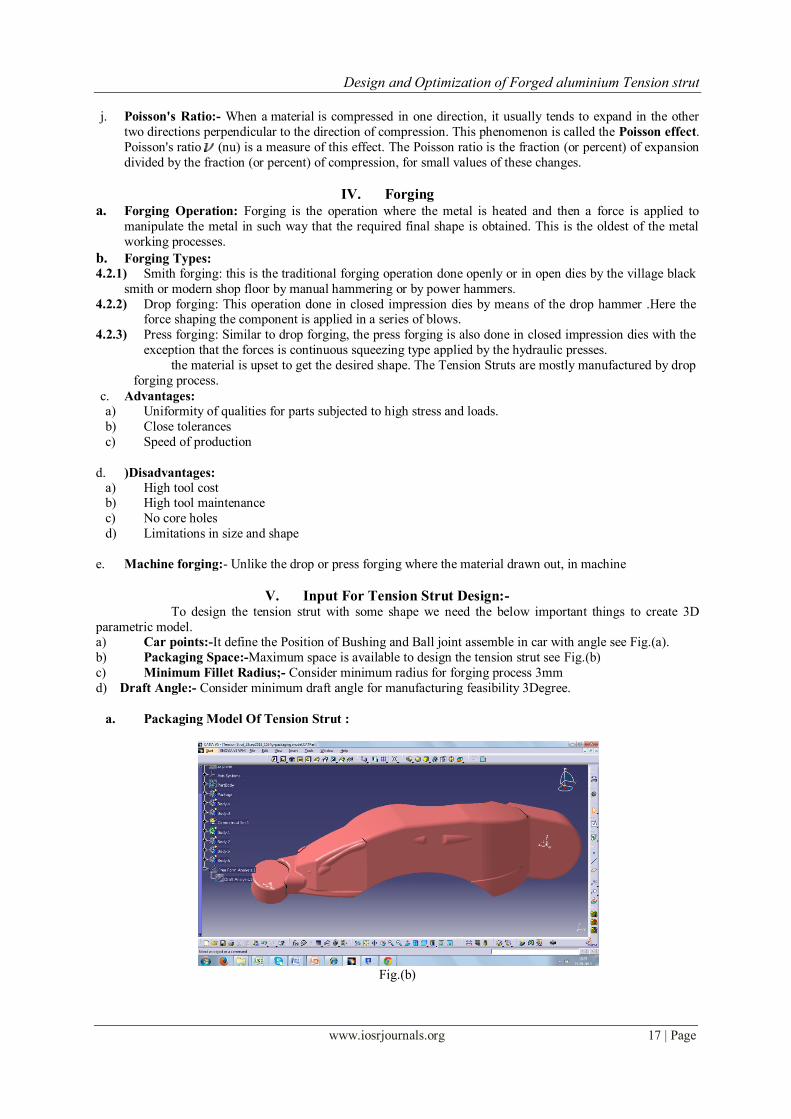
V. Input For Tension Strut Design:- To design the tension strut with some shape we need the below important things to create 3D
parametric model. a) Car points:-It define the Position of Bushing and Ball joint assemble in car with angle see Fig.(a).
b) Packaging Space:-Maximum space is available to design the tension strut see Fig.(b)
c) Minimum Fillet Radius;- Consider minimum radius for forging process 3mm
d) Draft Angle:- Consider minimum draft angle for manufacturing feasibility 3Degree.
a. Packaging Model Of Tension Strut :
Fig.(b)
Design and Optimization of Forged aluminium Tension strut
www.iosrjournals.org 18 | Page
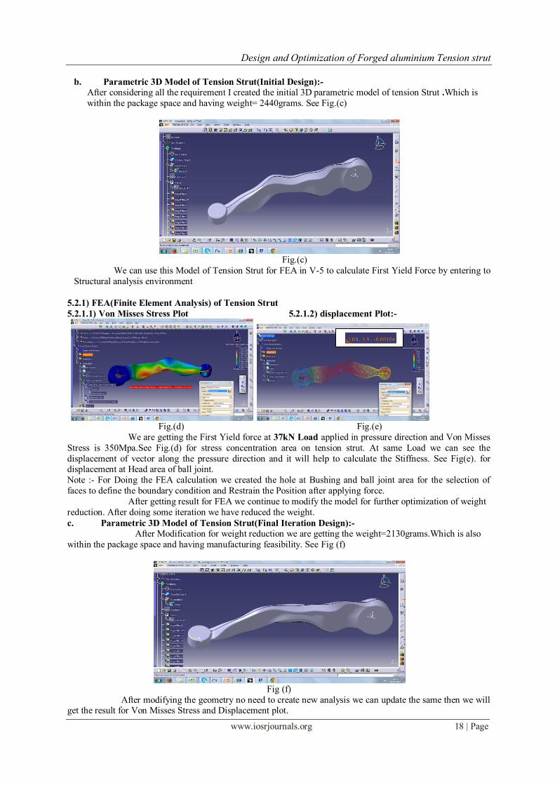
b. Parametric 3D Model of Tension Strut(Initial Design):-
After considering all the requirement I created the initial 3D parametric model of tension Strut .Which is
within the package space and having weight= 2440grams. See Fig.(c)
Fig.(c)
We can use this Model of Tension Strut for FEA in V-5 to calculate First Yield Force by entering to
Structural analysis environment
5.2.1) FEA(Finite Element Analysis) of Tension Strut
5.2.1.1) Von Misses Stress Plot 5.2.1.2) displacement Plot:-
Fig.(d) Fig.(e)
We are getting the First Yield force at 37kN Load applied in pressure direction and Von Misses
Stress is 350Mpa.See Fig.(d) for stress concentration area on tension strut. At same Load we can see the
displacement of vector along the pressure direction and it will help to calculate the Stiffness. See Fig(e). for displacement at Head area of ball joint.
Note :- For Doing the FEA calculation we created the hole at Bushing and ball joint area for the selection of
faces to define the boundary condition and Restrain the Position after applying force.
After getting result for FEA we continue to modify the model for further optimization of weight
reduction. After doing some iteration we have reduced the weight.
c. Parametric 3D Model of Tension Strut(Final Iteration Design):-
After Modification for weight reduction we are getting the weight=2130grams.Which is also
within the package space and having manufacturing feasibility. See Fig (f)
Fig (f)
After modifying the geometry no need to create new analysis we can update the same then we will get the result for Von Misses Stress and Displacement plot.

Design and Optimization of Forged aluminium Tension strut
www.iosrjournals.org 19 | Page
5.3.1) FEA(Finite Element Analysis) of Tension Strut
Von Misses Stress Plot and displacement Plot:-
5.3.1.1) Von Misses Stress Plot 5.3.1.2) displacement Plot:-
Fig (g) Fig (h)
We are getting the First Yield force at 32.1kN Load applied in pressure direction
and Von Misses Stress is 350Mpa.See Fig.(g) for stress concentration area on tension strut. At same Load we can
see the displacement of vector along the pressure direction and it will help to calculate the Stiffness. See Fig(h).
for displacement at Head area of ball joint.
We are getting FEA result of weight reduced model which is satisfying the requirement so we can
continue for Frequency analysis
VI. Frequency Analysis;- For frequency analysis we can consider same restrain for Static analysis without any masses. In
occurrence we can see the 10 mode of Tension strut having different frequency.
Fig (i):-Result at Mode.1 having Frequency=166.071Hz
Fig (j):-Result at Mode.2 having Frequency=460.349Hz
. Fig (i) Fig (j)
Fig (k):-Result at Mode.9 having Frequency=3738.77Hz Fig (l):-Result at Mode.10 having Frequency=4083.36Hz
Design and Optimization of Forged aluminium Tension strut
www.iosrjournals.org 20 | Page
. Fig (k) Fig (l)
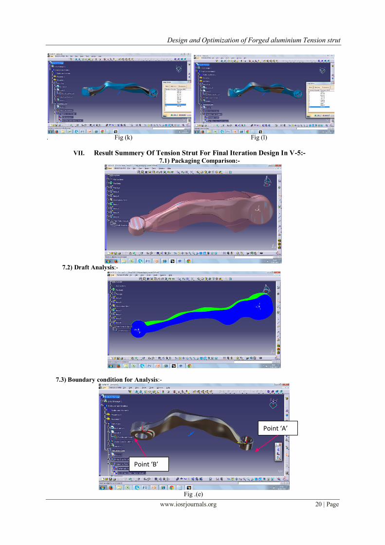
VII. Result Summery Of Tension Strut For Final Iteration Design In V-5:- 7.1) Packaging Comparison:-
7.2) Draft Analysis:-
7.3) Boundary condition for Analysis:-
Fig .(e)
Point ‘A’
Point ‘B’

Design and Optimization of Forged aluminium Tension strut
www.iosrjournals.org 21 | Page
At Point ‘B:- Three translation and one Rotation along pressure Axis
At Point ‘A:- Two translation except Pressure Axis.(Pressure axis-Imaginary Axis between point ‘A’&‘B’
VIII. Static Case Report Generated From V-5:- We can generate the total report of Static case from V-5 where we can see the consideration of FEA
calculation. See e.g.
e.g.
IX. Final Conclusion:- Final geometry of Tension strut is meeting all the FEA requirement for Static cases also having the manufacturing feasibility for forging operation checked with draft analysis in V-5.
After reducing the weight of Aluminium Tension strut in final iteration we are getting First yield Force, Von
Misses Stress and Stiffness as per requirement so ultimate it is reducing the material cost in mass production.
X. Future Scope:- The Design model can be optimised and can be reduce the weight as per the requirement by using
different materials by checking the previous analysis reports.
Reference:- [1]. http://forums.tccoa.com/showthread.php?t=124547
[2]. http://www.custommagnums.com/forums/engine-performance-mods/40365-how-replace-tension-struts.html
[3]. http://www.alu-stock.es/en/technical/information.html
[4]. http://www.witzenmann.in/download/Manual%20of%20metal%20bellows_0441e%20S%20174-199_2_04_10_20_web.pdf
[5]. http://www.grantadesign.com/education/datasheets/sciencenote.htm
Related Documents