MAE 4733 MECHATRONICS DESIGN TERM PROJECT-FALL 2011 REPORT Design and Implementation of an Autonomous Photovore Robot with Obstacle Avoidance SHUVRA BANIK BHARATH PAKALA 12/12/2011 SCHOOL OF MECHANICAL AND AEROSPACE ENGINEERING OKLAHOMA STATE UNIVERSITY

Design and Implementation of Autonomous Photovore Robot with Obstacle Avoidance (MAE 4733 Term Final Project Report)
Oct 25, 2015
MAE 4733 Term Final Project Report
Welcome message from author
This document is posted to help you gain knowledge. Please leave a comment to let me know what you think about it! Share it to your friends and learn new things together.
Transcript

MAE 4733 MECHATRONICS DESIGN
TERM PROJECT-FALL 2011 REPORT
Design and Implementation of an Autonomous Photovore Robot with
Obstacle Avoidance
SHUVRA BANIK BHARATH PAKALA
12/12/2011
SCHOOL OF MECHANICAL AND AEROSPACE ENGINEERING OKLAHOMA STATE UNIVERSITY

1
Abstract
A Photovore Robot is a robot which moves in the direction of light i.e. it will always move to a direction
where the intensity of light is higher. Obstacle Avoidance in a robot means an intelligence which will
guide the robot in such a way that it will always be able to avoid collisions with other objects. In this
project, mechanical and electronic designs have been accomplished for an Autonomous Photovore
Robot which also has the capability of Obstacle Avoidance.

2
Table Of Contents
Page Number
Introduction 3
Components 4
Hardware 4
IC 6
Working Principles 8
Differential Drive 8
Photovore Algorithm 9
Obstacle Avoidance 11
Operation 12
Circuit Diagram 12
Project Pictures 14
Applications 16
Problems And Recommendations 17
Problems 17
Recommendations 17
Future Works 18
Conclusion 19
References 21
Appendix 22
Project Code 22
3
Introduction
‘Photo’ means ‘Light’ in Greek and ‘Vore’ means ‘Swallow Up’ in Latin. So the literal meaning of a
Photovore Robot is a Light Eating Robot! In practical sense it is a robot which has affinity for light i.e. it is
a light-seeking robot. It will chase light and can be made using simplest of all sensor algorithms. Using
two light detecting sensors i.e. typical Photoresistors, this algorithm can be implemented. On the other
hand, Obstacle Avoidance is a familiar term in the field of robotics which stands for the capability of a
robot to avoid unnecessary collisions. The simplest algorithm for this can be done using IR Sensors
though with the use of image processing or artificial intelligence, very high precision algorithm for
Obstacle Avoidance can also be made. In this project the simplest approach has been made to detect
obstacles using IR Emitter and IR Detector.

4
Components
Hardware
Breadboard
A 3.25X2.125 400PNT breadboard has been used to place the electronic circuits.
Figure 1: Breadboard
Wires
Wires have been used to connect electronic devices on the breadboard.
Figure 2: Wires
Robot Chassis
A Pololu Robot Chassis RRC01A with cardboard has been used for the chassis.
Figure 3: Robot Chassis
Wheels

5
Two HS-5745MG wheels and one Tamiya Ball Caster has been used.
Figure 4: Wheels
Resistors
3 1K Resistors have been used.
Figure 5: Resistor
Batteries
One 9V and one 1.5V battery have been used.
Figure 6: Batteries
Servo Motors
2 Parallax Continuous Rotation Servo Motors have been used.
Figure 7: Servo Motor

6
Development Kit
One CCS PIC18F4520 Development Kit has been used.
Figure 8: Development Kit
Fasteners
Velcro fabric hook-and-loop fasteners have been used for attaching breadboard, development
kit and servo motors with the robot chassis.
Figure 9: Fastener
IC
Photoresistors
2 Photoresistors have been used to sense light.
Figure 10: Photoresistors
IR Sensors
One IR Emitter and One IR Detector have been used to detect obstacles.

7
Figure 11: IR Sensors
8
Working Principles
Differential Drive
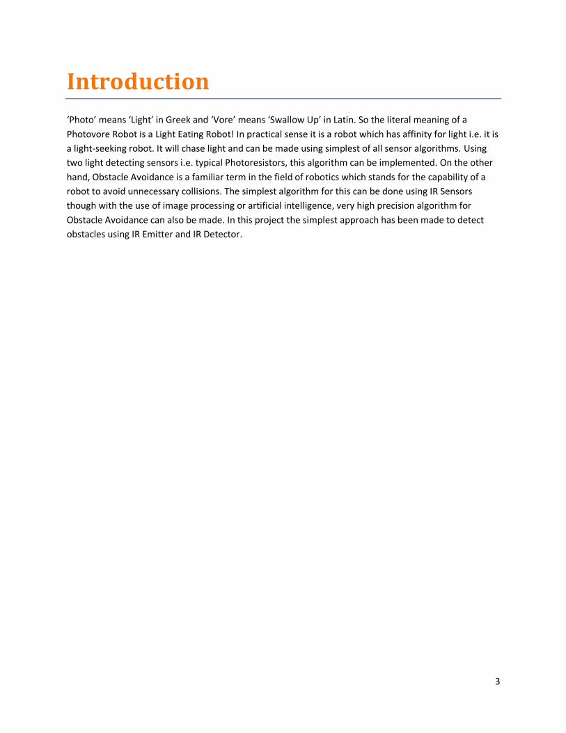
The movement of the robot has been done using Differential Drive algorithm. To move forward, both
front wheels are moved in the same direction. To move to right, right wheel is stopped and left wheel is
moved forward. To move to left, left wheel is stopped and right wheel is moved forward. To stop the
robot, both front wheels are stopped. A schematic diagram for Differential Drive algorithm is given
below (Drawn in Microsoft Word 2010).
Figure 12: Differential Drive
For the servo motors used in this project, the Base Positive Pulse Time is 1.5 ms with an interval
of 20 ms (From motor datasheet).
Figure 13: Base Positive Pulse Time
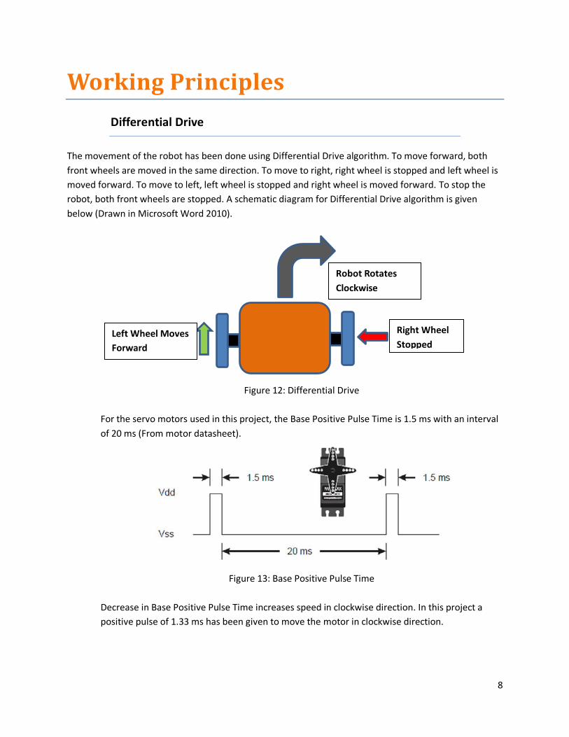
Decrease in Base Positive Pulse Time increases speed in clockwise direction. In this project a
positive pulse of 1.33 ms has been given to move the motor in clockwise direction.
Right Wheel
Stopped Left Wheel Moves
Forward
Robot Rotates
Clockwise
9
Figure 14: Movement in clockwise direction
Increase in Base Positive Pulse Time increases speed in counterclockwise direction. In this
project a positive pulse of 1.67 ms has been given to move the motor in counterclockwise
direction.
Figure 15: Movement in counterclockwise direction
Time interval between two positive pulses are always kept 20 ms for smooth operation.
Photovore Algorithm
Photovore Algorithm is implemented by using 2 photoresistors placed at the front side of the robot. A
photoresistor is a Light Dependent Resistor (LDR). So its resistance changes with the change in intensity
of the light falling upon it. In this project, a Voltage Divider Circuit has been made for each photoresistor
and voltage across each one has been measured using ADC. It has been found that the voltage across
each photoresistor decreases with the increase in the intensity of light. So the difference between
voltage of left and right photoresistors are taken to sense the intensity of light. The following figure
shows the Voltage Divider Circuit made across each photoresistor (Drawn in Microsoft Word 2010).

10
Figure 16: Voltage Divider Circuit (Photoresistor)
From calibration, it has been found that if the voltage difference is more than 0.08V, then the robot
should change the direction to right of left based on the intensity of light. So a C code has been written
using this criterion. The following figure shows a schematic diagram of Photovore Algorithm (Drawn in
Microsoft Word 2010).
Figure 17: Photovore Algorithm
More Light On
Right
Photoresistor
Robot Rotates
Clockwise
ADC Increase in Light
Decrease in Vout

11
Obstacle Avoidance
It has been implemented using one IR Emitter and one IR Detector. The IR Emitter emits IR light
continuously in the forward direction. If there is an obstacle in the front, then IR light bounces back. The
IR Detector receives the reflected IR light. An IR Detector is actually an IR Phototransistor which converts
IR light into voltage. In this project, it is found that the voltage across the IR Detector decreases with the
increase in IR light upon it. So a Voltage Divider has been made across the IR Detector and voltage has
been measured using ADC. The following figure shows the Voltage Divider Circuit made across the IR
Detector (Drawn in Microsoft Word 2010).
Figure 18: Voltage Divider Circuit (IR Detector)
For detecting a distance of 6 inches in room light, if the voltage is less than 4.94V, then robot has been
turned to right. This voltage has been found after calibration. The following figure shows a schematic
diagram of Obstacle Avoidance (Drawn in Microsoft Word 2010).
ADC
Decrease in Vout Increase in IR
IR Emitter
(1 K) IR Detector
Obstacle

12
Figure 19: Obstacle Avoidance
Operation
When power is given to microcontroller, by default, it works as a Photovore Robot. If anyone presses
button (PIN_A4) on the Development Kit, then an external interrupt occurs at PIN_B0 and the robot
works as an Obstacle Avoiding Robot. Another interrupt will make the robot to work as a Photovore
Robot and these operations continue alternatively with each button press until power is taken off.
Obstacle
Turns to Right
IR Detector
IR Light Reflects
IR Emitter
Around 6 inches

13
Circuit Diagram
The circuit diagram of project is given below (Drawn in Proteus ISIS Professional 7.7 SP2).
Figure 20: Circuit Diagram

14
Project Pictures
Several pictures of the final setup are given below:
Figure 21: Sensors
Figure 22: Circuits

15
Figure 23: Final Look

16
Applications
Photovore Algorithm and Obstacle Avoidance can be utilized in many ways such as:
A Photovore Robot can be used with a solar cell to get direct sunlight all the time of the day.
Obstacle Avoidance can be used to avoid undesired collisions such as in Mars Rovers.

17
Problems And Recommendations
Problems
Problems faced during this project were:
Same speed in both servo motors is not found using the same pulse rate.
The wheels slide on the floor due to lack of enough friction.
In order to keep the module compact, the chassis has been made smaller which in turn made
the placement of circuit boards and batteries clumsy.
Calibration of photoresistors is difficult because their resistance changes with the change in light
intensity and source.
Calibration of IR detector is difficult because voltage across it changes with respect to light
source (i.e. in sunlight or in room light), color and also surface structure of obstacle.
Recommendations
Some recommendations for the above stated problems are:
Using servos of same speed.
Using wheels having better friction.
Allocating enough space for the circuit boards and batteries.
Using better photoresistors with better calibration.
Using Sharp IR Range Finder sensors instead of IR Detectors.

18
Future Works
As an extension of this project these future works can be done:
A Photophobe Robot can be made by changing the code of Photovore Robot which will move
away from light or will seek darkness.
A Fire Fighting Robot can be made using IR Detector of this robot. In fact it was almost done but
enough time to write an efficient code was not available.
A Line Following Robot can also be made using the Photoresistors of this robot.

19
Conclusion
Our project can be considered as a success. We have applied our knowledge attained from MAE 4733
course and could successfully run the project. A video demonstration of this project has been given
during presentation and questions from the audience have been answered. We hope everyone has
enjoyed our work.

20
References
We have got a lot of information regarding this project from the following site:
1) Society Of Robots (http://www.societyofrobots.com/)
Figures for the Components section have been taken from these sites:
1) Figure 1:
http://simonpstevens.com/Content/Projects/Microcontrollers/Posts/MicrocontrollerIntroEquipmen
t_Files/Breadboard.jpg
2) Figure 2:
http://itp.nyu.edu/~bms415/blog/wp-content/uploads/2011/09/wire-jumpers.jpg
3) Figure 3:
http://doc-14-8g-
3dwarehouse.googleusercontent.com/3dwarehouse/secure/hhulr73hmmak89paul31eote4ben7ngk
/20i0m4vfbhvn47ueuk69mb4m7ob8tbq8/1323604800000/lt/*/275b87677bfaf417c048bd5374389c
59?ts=1233007659000&ctyp=other
4) Figure 4:
http://www.servocity.com/assets/images/316SH_on_servo.jpg
http://www.pololu.com/picture/0J263.300.jpg
5) Figure 5
http://www.basicmicro.com/assets/images/1k_resistor.jpg
6) Figure 6
http://www.a1gifts.co.uk/images/prodimages/Duracell_9v_imageL.jpg
http://alkalinebatteries.us/images/AA_Coppertop2.jpg
7) Figure 7
http://www.parallax.com/Portals/0/Images/Prod/9/900/900-00008-M.jpg
8) Figure 8
http://www.ccsinfo.com/product_info.php?products_id=18F452kit

21
9) Figure 9
http://1.bp.blogspot.com/_4CTz0Ff0Msc/TNyeUn-4E-I/AAAAAAAAAOE/KunJ2-
Vd15Y/s1600/Velcro.jpg
10) Figure 10
http://imgusr.tradekey.com/p-5717779-20111012020505/cds-photoresistor.jpg
11) Figure 11
http://www.t2retail.co.uk/lg_images/Dayga-T2-infrared_Emitter_And_Detector.jpg
22
Appendix
Project Code
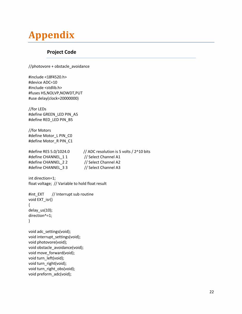
//photovore + obstacle_avoidance #include <18f4520.h> #device ADC=10 #include <stdlib.h> #fuses HS,NOLVP,NOWDT,PUT #use delay(clock=20000000) //for LEDs #define GREEN_LED PIN_A5 #define RED_LED PIN_B5 //for Motors #define Motor_L PIN_C0 #define Motor_R PIN_C1 #define RES 5.0/1024.0 // ADC resolution is 5 volts / 2^10 bits #define CHANNEL_1 1 // Select Channel A1 #define CHANNEL_2 2 // Select Channel A2 #define CHANNEL_3 3 // Select Channel A3 int direction=1; float voltage; // Variable to hold float result #int_EXT // Interrupt sub routine void EXT_isr() { delay_us(10); direction^=1; } void adc_settings(void); void interrupt_settings(void); void photovore(void); void obstacle_avoidance(void); void move_forward(void); void turn_left(void); void turn_right(void); void turn_right_obs(void); void preform_adc(void);

23
void main(void) { interrupt_settings(); adc_settings(); while(TRUE) { photovore(); obstacle_avoidance(); } } void preform_adc() { int16 AD_value; // Variable to hold 10 bit result delay_us(100); // Time given to complete AD conversion AD_value=read_adc(); // Gets 10 bit AD conversion result voltage=(float)AD_value*RES; } void photovore(void) { float voltage_left,voltage_right,vore_diff; while(direction==1) { move_forward(); set_adc_channel(CHANNEL_1); // Select channel AN1 for AD conversion preform_adc(); voltage_left=voltage; set_adc_channel(CHANNEL_2); // Select channel AN1 for AD conversion preform_adc(); voltage_right=voltage; vore_diff=voltage_left-voltage_right; if (vore_diff>.08) { turn_right(); }

24
else { if(vore_diff<0.0) {vore_diff=abs(vore_diff); if (vore_diff>.08) { turn_left(); } } } } } void move_forward() { output_high(Motor_L); delay_us(1670); output_low(Motor_L); delay_us(20000); output_high(Motor_R); delay_us(1330); output_low(Motor_R); delay_us(20000); } void turn_left(void) { int i; output_low(RED_LED); output_low(Motor_L); for(i=0;i<20;++i) { output_high(Motor_R); delay_us(1330); output_low(Motor_R); delay_us(20000); } output_high(RED_LED); }

25
void turn_right(void) { int i; output_low(GREEN_LED); output_low(Motor_R); for(i=0;i<20;++i) { output_high(Motor_L); delay_us(1670); output_low(Motor_L); delay_us(20000); } output_high(GREEN_LED); } void obstacle_avoidance(void) { while(direction==0) { move_forward(); set_adc_channel(CHANNEL_3); // Select channel AN1 for AD conversion preform_adc(); if (voltage<4.94) { turn_right_obs(); } } } void turn_right_obs(void) {

26
int i; output_low(GREEN_LED); output_low(Motor_R); for(i=0;i<88;++i) { output_high(Motor_L); delay_us(1670); output_low(Motor_L); delay_us(20000); } output_high(GREEN_LED); } void interrupt_settings(void) { set_tris_b(0x1); enable_interrupts(INT_EXT); enable_interrupts(GLOBAL); } void adc_settings(void) { setup_adc_ports(AN0_TO_AN5); // Specify ADC channel (here only AN1 is needed) setup_adc(ADC_CLOCK_INTERNAL); // Use internal clock to initiate ADC }
Related Documents