Design and Implementation of a Voice-Driven Animation System by Zhijin Wang B.Sc., Peking University, 2003 A THESIS SUBMITTED IN PARTIAL FULFILLMENT OF THE REQUIREMENTS FOR THE DEGREE OF MASTER OF SCIENCE in THE FACULTY OF GRADUATE STUDIES (Computer Science) THE UNIVERSITY OF BRITISH COLUMBIA February 2006 © Zhijin Wang, 2006

Welcome message from author
This document is posted to help you gain knowledge. Please leave a comment to let me know what you think about it! Share it to your friends and learn new things together.
Transcript

Design and Implementation of a Voice-Driven Animation System
by
Zhijin Wang
BSc Peking University 2003
A THESIS SUBMITTED IN PARTIAL FULFILLMENT OF
THE REQUIREMENTS FOR THE DEGREE OF
MASTER OF SCIENCE
in
THE FACULTY OF GRADUATE STUDIES
(Computer Science)
THE UNIVERSITY OF BRITISH COLUMBIA
February 2006
copy Zhijin Wang 2006
Abstract
This thesis presents a novel multimodal interface for directing the actions of computer
animated characters and camera movements Our system can recognize human voice input
combined with mouse pointing to generate desired character animation based on motion
capture data We compare our voice-driven system with a button-driven animation interface
that has equivalent capabilities An informal user study has indicated that our voice-user
interface (VUI) is faster and simpler for the users than traditional graphical user interface
(GUI) The advantage of VUI is more obvious when creating complex and high-detailed
character animation Applications for our system include creating computer character
animation in short movies directing characters in video games storyboarding for film or
theatre and scene reconstruction
ii
Table of Contents
Abstract ii
Table of Contents iii
List of Figures vi
Acknowledgements vii
1 Introduction 1
11 Animation Processes1
12 Motivation 2
13 System Features 3
14 An Example 4
15 Contributions 6
16 Thesis Organization 6
2 Previous Work7
21 History of Voice Recognition7
22 Directing for Video and Film9
221 Types of Shots9
222 Camera Angle 10
223 Moving Camera Shots 12
23 Voice-driven Animation13
24 Summary15
iii
3 System Overview16
31 System Organization16
32 Microsoft Speech API18
321 API Overview 19
322 Context-Free Grammar 20
323 Grammar Rule Example 21
33 Motion Capture Process22
34 The Character Model 25
4 Implementation 28
41 User Interface 28
42 Complete Voice Commands29
43 Motions and Motion Transition 31
44 Path Planning Algorithm32
441 Obstacle Avoidance32
442 Following Strategy34
45 Camera Control35
46 Action Record and Replay36
47 Sound Controller36
48 Summary37
5 Results38
51 Voice-Driven Animation Examples 38
511 Individual Motion Examples 38
512 Online Animation Example 40
513 Off-line Animation Example42
514 Storyboarding Example 45
52 Comparison between GUI and VUI47
iv
6 Conclusions 50
61 Limitations50
62 Future Work 51
Bibliography53
v
List of Figures
Figure 11 Example of animation created using our systemhelliphelliphelliphelliphelliphelliphelliphelliphelliphelliphellip 5
Figure 31 The architecture of the Voice-Driven Animation Systemhelliphelliphelliphelliphelliphelliphellip17
Figure 32 SAPI Engines Layouthelliphelliphelliphelliphelliphelliphelliphelliphelliphelliphelliphelliphelliphelliphelliphelliphelliphelliphelliphellip19
Figure 33 Grammar rule examplehelliphelliphelliphelliphelliphelliphelliphelliphelliphelliphelliphelliphelliphelliphelliphelliphelliphelliphelliphelliphellip21
Figure 34 Capture Space Configurationhelliphelliphelliphelliphelliphelliphelliphellip23
Figure 35 Placement of camerashelliphelliphelliphelliphelliphelliphelliphelliphelliphelliphelliphelliphelliphelliphelliphelliphelliphelliphelliphelliphellip24
Figure 36 The character hierarchy and joint symbol tablehelliphelliphelliphelliphelliphelliphelliphelliphelliphelliphelliphellip26
Figure 37 The calibrated subjecthelliphelliphelliphelliphelliphelliphellip27
Figure 41 Interface of our systemhelliphelliphelliphelliphelliphelliphelliphelliphelliphelliphelliphelliphelliphelliphelliphelliphelliphelliphelliphelliphellip29
Figure 42 Voice commands listhelliphelliphelliphelliphelliphelliphelliphelliphelliphelliphelliphelliphelliphelliphelliphelliphelliphelliphelliphelliphelliphellip30
Figure 43 Motion Transition Graphhelliphelliphelliphelliphelliphelliphelliphelliphelliphelliphelliphelliphelliphelliphelliphelliphelliphelliphelliphellip31
Figure 44 Collision detection exampleshelliphelliphelliphelliphelliphelliphelliphelliphelliphelliphelliphelliphelliphelliphelliphelliphelliphellip33
Figure 45 Path planning exampleshelliphelliphelliphelliphelliphelliphelliphelliphelliphelliphelliphelliphelliphelliphelliphelliphelliphelliphelliphellip34
Figure 46 Following examplehelliphelliphelliphelliphelliphelliphelliphelliphelliphelliphelliphelliphelliphelliphelliphelliphelliphelliphelliphelliphelliphellip34
Figure 51 Sitting down on the floorhelliphelliphelliphelliphelliphelliphelliphelliphelliphelliphelliphelliphelliphelliphelliphelliphelliphelliphelliphellip39
Figure 52 Pushing the other characterhelliphelliphelliphelliphelliphelliphelliphelliphelliphelliphelliphelliphelliphelliphelliphelliphelliphelliphellip39
Figure 53 Online animation examplehelliphelliphelliphelliphelliphelliphelliphelliphelliphelliphelliphelliphelliphelliphelliphelliphelliphelliphellip41
Figure 54 Off-line animation examplehelliphelliphelliphelliphelliphelliphelliphelliphelliphelliphelliphelliphelliphelliphelliphelliphelliphelliphellip44
Figure 55 Storyboarding examplehelliphelliphelliphelliphelliphelliphelliphelliphelliphelliphelliphelliphelliphelliphelliphelliphelliphelliphelliphelliphellip47
Figure 56 Average time of creating online animation using both interfaceshelliphelliphelliphelliphellip48
Figure 57 Average time of creating off-line animation using both interfaceshelliphelliphelliphellip49
vi
Acknowledgements
I would like to express my gratitude to all those who gave me the possibility to complete this
thesis The first person I would like to thank is my supervisor Michiel van de Panne for
providing this excellent research opportunity His inspiration his encouragement and his
expertise in computer character animation were very helpful to me during the whole project
and the thesis-writing I could not have completed all the work without his invaluable
guidance and support
I would also like to thank Robert Bridson who gave me very good suggestions and
useful comments on how to improve my thesis
I am very grateful to Kangkang Yin who spent a lot of time teaching me and working
with me on the Vicon Motion Capture System I also wish to thank Dana Sharon and Kevin
Loken for making the motion capture sessions a lot of fun to me
Finally I am forever indebted to my parents and my wife Tong Li for their understanding
encouragement and endless love
vii
Chapter 1
Introduction
By definition animation is the simulation of movement created by displaying a series of
pictures or frames [1] To create the illusion of movement a picture is displayed on the
screen then quickly replaced by a new picture similar to the previous one but shifted or
changed slightly In the past when animation was created by hand this process required a
great deal of time manpower and recording equipment However today the animation
process has become dramatically simpler What was once done with pencils sheets and
paints by a group of animators can now be accomplished by a single person with a personal
computer Not only has it become easier for people to create animation using computers the
application of computer animation has also spread into many aspects of our lives including
advertising architecture education industrial training motion pictures video games and
scientific visualization
11 Animation Processes
Broadly speaking there are three types of processes to create computer animation
keyframing physics-based simulation and motion capture Keyframing is a popular method
for animating articulated figures because it allows for artistic expressiveness by providing
unlimited control to the animator The animator defines a set of keyframes in which the
properties of the character such as its position orientation and joint angles are described at
specific instants in time The motion is then obtained by simply interpolating the property
values between these keyframes typically with cubic splines The drawback of this process is
that it requires significant time and effort for the animator Defining a movement often
1
requires a high level of detail to ensure that the interpolation curves induce the desired
collision-free motion This is time consuming and generating new motions must happen
offline
Physics-based simulation involves using mathematical equations to model natural
phenomena and then using numerical methods to compute an efficient and accurate solution
to the equations in order to create realistic passive motions One class of physics-based
animation uses forward-dynamic simulation and it has been used to analyze and reconstruct
active human motions such as running falling diving and so on An alternative technique is
that of ldquospacetime constraintsrdquo which optimizes a complete motion trajectory to
automatically generate the movements of physically simulated characters However
specifying the right control to achieve a desired result remains a difficult problem
Motion capture is the process of capturing the movement of a real object or person and
mapping it onto a computer generated object or person to create natural looking animation
For character animation motion capture systems are used to capture the motions of human
actors by placing markers at various key points on the actors Multiple cameras are used to
observe and reconstruct the position of those markers in real time and their motions are then
used to reconstruct the motion of the underlying skeleton An advantage of motion capture
over traditional animation techniques such as keyframing and simulation is the capability of
real-time visualization and the high quality of the generated animation However there is no
easy way to modify the captured data to interactively generate new motions for different
characters or for different environments
12 Motivation
No matter which one of the above methods is used to produce the animation user interaction
is always an important part of an interactive computer animation system Without a good
interface even an otherwise powerful system cannot enable the creation of good animation
2
Unfortunately many current computer animation systems have complex interfaces and as a
result require extensive training or reading of manuals in order to learn how to use the system
There are usually a large number of buttons on various panels and many keyboard shortcuts
for an animator to select desired motions or to create diverse animation effects The animator
must use a mouse and keyboard to specify the path along which the character is moving as
well as the specific types of motions to be carried at This is time-consuming even when
creating fairly generic motions For example if a character is to perform a slow walk
followed by running at normal speed and then followed by fast walking while waving a hand
it is necessary to look for specific buttons among multiple panels in order to select the correct
options This kind of visual search is inefficient and distracting for an animator trying to focus
on the animation
To improve user interaction and simplify the animation process we present a novel
voice-driven interface for computer animation systems This has strong parallels with
filmmaking where there is a director in charge of filming directing the actions of actors and
the placement of cameras If the director is not satisfied with a particular scene he can either
re-shoot the scene again or edit the footage in post-processing The direction is often
conducted through oral communication which is the most natural way for both director and
actors In our system the user becomes the director of the animation He can instruct the
movement of the characters and cameras using his voice much like a movie director albeit
with a more limited vocabulary Thus we attempt to directly implement the director-actor
metaphor for an animation system
13 System Features
To enable the voice-driven feature our animation system uses Microsoft Speech API as the
voice recognition engine We define a set of grammar rules for recognizable voice commands
All speech from the microphone is processed by the system If the spoken words match one of
3
the grammar rules it can be recognized as a voice command that then triggers a motion for
the character a camera motion or a system function
Our pre-defined voice commands are divided into three classes The first class of voice
commands allows users to control the actions of the characters Our characters can perform
simple actions such as walking running hand waving as well as more abstract actions such
as following another character or walking to a specified location while avoiding obstacles
The second class of voice commands allows for the control of camera movement The user
who is the director of the animation can make use of different classical film camera angles
such as an ldquoover the shoulder shotrdquo ldquopanning shotrdquo ldquozoom inrdquo and ldquozoom outrdquo The third
class of voice commands relates to global functions such as opening and saving animation
files resetting the scene and so forth
Our system can be used both online and off-line During online use the characters and
cameras react in real-time according to the instructions they receive from the user To create
off-line animation the user gives a series of instructions followed by an ldquoactionrdquo command to
indicate the start of the animation analogous to what a film director might do
Our system is also able to record and playback spoken dialogue This is a useful feature
for directly adding scripted dialogue to a storyboard or animation This is treated as a special
mode where the voice recognition process is temporarily disabled in order to avoid any
potential false recognition by the speech engine
14 An Example
Figure 11 shows an example of creating animation using our voice-driven animation system
The user directs the movement of the character by speaking into the microphone connected to
the computer The speech engine of our system will then analyze the speech input If any of
the voice commands is recognized the animation engine will find the corresponding motion
clip in our motion capture database Spoken dialogue can be added and additional mouse
4
input may be provided by the user to specify certain locations The desired animation will
then be generated and displayed on the screen as a visual feedback to the user
More specific and detailed examples are given in Chapter 5
Speech
Engine
Animation
Engine
Speech Input
Animation
Voice Commands Spoken
Dialogue
Mouse Input
Motion Capture
Database
Figure 11 Example of animation created using our system
5
15 Contributions
The primary contribution of this thesis is to provide a method for the multimodal interactive
control of 3D computer animation using spoken commands in order to approximate the
director-actor metaphor Specifically we present a voice-driven interface for creating
character animation based on motion capture data This interface is able to accept voice
commands and pointing input which allows a user with little knowledge of computer
animation techniques to quickly create character animations
We develop a system that implements this voice-driven interface as well as a
functionally equivalent GUI-based interface We qualitatively and quantitatively compare the
performance of creating computer animation using this voice-driven interface with that of the
GUI-based interface Our system demonstrates the feasibility of directing computer animation
using only spoken directives as well as the potential advantages of voice-driven interaction
over the traditional mouse and keyboard interaction
16 Thesis Organization
The remainder of this thesis is structured as follows After reviewing previous related work in
Chapter 2 we provide an overview of our system in Chapter 3 Chapter 4 describes the
components of our interface and explains the details of our implementation Chapter 5
demonstrates a variety of results obtained using our interface Finally conclusions and future
work are presented in Chapter 6
6
Chapter 2
Previous Work
Voice recognition technology has evolved rapidly over the past decades It is now being
widely used in user interfaces to allow the user to provide input to an application with his or
her own voice typically as a substitute for typing on a keyboard or clicking a mouse In this
chapter we first provide a brief historical overview of voice recognition technology We then
give a short introduction to directing for video and film Lastly we review work in animation
that relates to the use of voice and natural language
21 History of Voice Recognition
Interestingly a toy company logged the first success story in the field of voice recognition
many decades before major research in the area was considered The Radio Rex from 1920
was a celluloid dog that responded to its spoken name Lacking the computation power that
drives recognition devices today Radio Rex was a simple electromechanical device The dog
was held within its house by an electromagnet As current flowed through a circuit bridge the
magnet was energized The acoustic energy of the vowel sound of the word ldquoRexrdquo caused the
bridge to vibrate breaking the electrical circuit and allowing a spring to push Rex out of his
house While Radio Rex was not a commercial success the toy was an important first
demonstration of voice recognition [2]
During the 1940s and 1950s the US Department of Defense (DOD) and MIT became the
largest contributors to the speech recognition field The US DOD was driven by an interest in
automatic interception and translation of Russian radio transmissions The actual output their
devices generated from Russian statements was more amusing than accurate however and the
7
project was deemed a dismal failure [3]
Speech research was hamstrung because systems were designed that acknowledged only
complete words and sentences They would attempt to statistically guess the words following
another word But they took no account of the sounds used in the formation of the words
themselves These word formation elements are called phonemes and are sounds such as TH
PH etc Work at IBM derived the first statistical correlations between phenome sounds and
the words they ultimately formed [4] This was to prove the cornerstone of future research
By 1975 Jim Baker from Carnegie Mellon had developed his revolutionary Dragon
speech recognition model IBM continued to pioneer their statistical approach to speech
recognition adapting many algorithms from information theory By 1985 they had developed
a system capable of discerning 5000 different words and phrases [5]
Although much speech research took place over the next ten years little in the way of
commercially-viable voice recognition-related products materialized Then in 1995 IBM
who had conducted intensive research for 50 years but had released nothing commercially
finally entered into the consumer marketplace with VoiceTypereg and later ViaVoicereg In April
of 1997 Dragon Systems countered introducing Naturally Speakingreg the first large
vocabulary continuous speech software available
The development of voice recognition technology has facilitated the design of
multimodal interactions One of the earliest multimodal interfaces was built in 1980 by
Richard Bolt [6] The ldquoPut-That-Thererdquo system used basic speech recognition and equipment
that could track where the user was pointing This simple system allowed users to move
colored shapes around on a screen It was able to allow the free use of pronouns and figure
out which object the user was talking about The system also allowed users to give objects
names and then use those names to refer to the objects The system was a first attempt at
creating a more natural user interface
8
22 Directing for Video and Film
Video and film directors are artists who can take a completed script and imaginatively
transform it into exciting sounds and images Directors creatively organize many facets of
production to produce works of art They know how and when to use different types of
camera shots and have mastered the use of composition image qualities transition devices
and relations of time and space Directors know when and how to use different types of sound
and how to control sound and image interaction By using all of their creative powers
directors are able to produce films and video programs that have lasting value [7]
Directors prepare a shooting script by indicating specific types of images and sounds to
be recorded within each scene In order to record the different scenes and sequences described
in the script the director must organize the activities of many different people who are
involved in production The director must be able to communicate precisely and quickly with
cast and crew A specific communication system and language must be understood and
followed by each person as a command is directed at them
221 Types of Shots
A directors ability to select and control visual images begins with an understanding of
specific types of shots The camera can be close to or far away from the subject It can remain
stationary or move during a shot The shots commonly used in video and film production can
be described in terms of camera-to-subject distance camera angle camera movement and
shot duration
Long Shot (LS)
The long shot orients the audience to subjects objects and settings by viewing them from a
distance this term is sometimes used synonymously with the terms establishing shot wide
9
shot or full shot An establishing shot (ES) generally locates the camera at a sufficient
distance to establish the setting Place and time are clearly depicted A full shot (FS) provides
a full frame (head-to-toe) view of a human subject or subjects
Medium Shot (MS)
A medium shot provides approximately a three-quarter (knee-to-head) view of the subject
The extremes in terms of camera-to-subject distance within this type of shot are sometimes
referred to as a medium long shot (MLS) and a medium close-up (MCU) The terms two-shot
and three-shot define medium shots in which two or three subjects respectively appear in the
same frame
Close Shot (CS) or Close-Up (CU)
The terms close shot and close-up are often used synonymously A close-up refers to the
isolation of elements in the shot and normally indicates the head and shoulders of a person
When someone is making an important or revealing statement or facial gesture a close-up
will draw the audiencersquos attention to that event Close-ups focus and direct attention and
create dramatic emphasis When they are overused however their dramatic impact is
severely reduced A very close camera position is sometimes called an extreme close-up
(ECU)
222 Camera Angle
The camera angle is frequently used to establish a specific viewpoint such as to involve the
audience in sharing a particular characterrsquos perspective on the action The goal may be to
enhance identification with that personrsquos psychological or philosophical point of view
10
Point-of-View Shot (POV Shot)
A point-of-view shot places the camera in the approximate spatial positioning of a specific
character It is often preceded by a shot of a character looking in a particular direction which
establishes the characterrsquos spatial point of view within the setting followed by a shot of that
same characterrsquos reaction to what he or she has seen The latter shot is sometimes called a
reaction shot A closely related shot is the over-the-shoulder shot (OS) The camera is
positioned so that the shoulder of one subject appears in the foreground and the face or body
of another is in the background Another variation on the point-of-view shot is the subjective
shot which shows us what the person is looking at or thinking about Like point-of-view
shots subjective shots offer a nonobjective viewpoint on actions and events and can enhance
audience identification with more subjective points of view
Reverse-Angle Shot
A reverse-angle shot places the camera in exactly the opposite direction of the previous shot
The camera is moved in a 180-degree arc from the shot immediately preceding it
Low-Angle Shot
A low-angle shot places the camera closer to the floor than the normal camera height which
is usually at eye level A low angle tends to exaggerate the size and importance of the subject
High-Angle Shot
A high-angle shot places the camera high above the subject and tends to reduce its size and
importance
Overhead Shot
An overhead shot places the camera directly overhead and creates a unique perspective on the
action This can sometimes be accomplished by a set of periscope mirrors and overhead track
or by attaching the camera to an airplane helicopter or crane
11
223 Moving Camera Shots
A moving camera adds new information to the frame and often alters spatial perspective A
moving camera shot can maintain viewer interest for a longer period of time than a stationary
camera shot
Pan Shot
A camera can be panned by simply pivoting it from side to side on a fixed tripod or panning
device This shot is often used to follow action without having to move the camera from its
fixed floor position
Tilt Shot
A camera tilt is accomplished by moving the camera up and down on a swivel or tilting
device This shot is also used to follow action such as a person standing up or sitting down It
can also be used to follow and accentuate the apparent height of a building object or person
Pedestal Shot
A camera can be physically moved up and down on a pedestal dolly A hydraulic lift moves
the camera vertically up and down within the shot such as when a performer gets up from a
chair or sits down A pedestal shot allows the camera to remain consistently at the same
height as the performer unlike a tilt shot where the camera height usually remains unchanged
Pedestal shots are rare but a pedestal is often used to adjust the height of the camera between
shots
Zoom Shot
A zoom can be effected by changing the focal length of a variable focal-length lens in
midshot A zoom shot differs from a dolly shot in that a dolly shot alters spatial perspective by
actually changing the spatial positioning of objects within the frame During a zoom shot the
12
apparent distance between objects appears to change because objects are enlarged or
contracted in size at different rates During a zoom-in objects appear to get farther apart and
during a zoom-out they seem to get closer together
Dolly Shot
A dolly shot is a shot in which the camera moves toward or away from the subject while
secured to a movable platform on wheels It is often needed to follow long or complicated
movements of performers or to bring us gradually closer to or farther away from a person or
object
Trucking Shot
In a trucking shot the camera is moved laterally (from side to side) on a wheeled dolly The
camera may truck with a moving subject to keep it in frame If the dolly moves in a
semicircular direction the shot is sometimes referred to as an arc or camera arc
Tracking Shot
A tracking shot uses tracks laid over rough surfaces to provide a means of making smooth
camera moves in otherwise impossible locations
Crane or Boom Shot
The camera can be secured to a crane or boom so that it can be raised and lowered or moved
from side to side on a pivoting arm This type of shot can create a dramatic effect when it
places the subject in the context of a large interior space or a broad exterior vista
23 Voice-driven Animation
Voice recognition technology is currently used in automobiles telephones personal digital
13
assistants (PDAs) medical records e-commerce text dictation and editing Like the mouse
keyboard and the trackball voice recognition can enhance the control of a computer and
improve communication We discuss three animation systems which resemble our own work
by making use of voice recognition technology
The interactive movie system [8] has the capability of creating a virtual world with
various kinds of realistic scenes and computer characters People can enter cyberspace and
experience the stories of the virtual world through interactions with the characters and the
environments of the world The interactions include voice and gesture recognition However
only exaggerated gestures rather than minute gestures could be recognized because of low
lighting in the area where the system played As a result the system ran almost exclusively on
voice recognition and players were limited to available modalities that allowed only simple
interaction This system differs from ours in that the progress of the story is pre-defined and
mostly controlled by the system the user is only acting as a participant who can interact with
the system at some branch points where the results from voice or gesture recognition will
determine the future development of the story In our system the user takes the role of the
director and controls the entire storyline of the animation
VIRTUAL THEATER [9] provides a collaborative virtual environment for industrial
tele-training Instead of working with physical objects these are represented by virtual objects
that can then be placed in a virtual environment accessible to many users The users
represented by avatars can manipulate and interact with the objects as in the real world
gaining valuable experience and training before using the real equipment The environment
can be fully controlled in a wireless fashion where speech commands and user gestures are
used as input allowing for a more comfortable interaction between the human participants
For example the user may simply say pre-defined commands such as Go to the table for the
avatar to perform or may change views by saying Table Top View and so on However the
system is limited to a particular use eg training operators of ATM switching equipment in
this case The pre-defined high level actions make it impossible to create any free-style
animation with this system
14
Perhaps the most closely related work to ours is that of [10] This presents the design and
development of a Voice User Interface (VUI) which maps predefined voice commands to a
set of behavioral motions for humanoid avatars using Extensible 3D (X3D) graphics It uses
Virtual Reality Modeling Language (VRML) Humanoid Animation (H-Anim) Standard and
Java Speech API The VUI maps between human voice commands and a set of animations of
the avatar thus providing voice access to the animation application Graphical User Interface
(GUI) is also provided as an alternative interaction Their work demonstrates the possibility
of integrating speech-recognition technology into Networked Virtual Environments
(Net-VEs) However it cannot record voice dialogues and the avatar is restricted to do only a
small number of actions such as standing walking and jumping There is no control over the
camera shots either
24 Summary
In this chapter we have provided an overview of voice recognition technology directing and
previous work in animation based on these Our system shares the same motivation as most
applications in this category to speed up and simplify the human-computer interaction using
natural spoken languages We have developed a computer animation system with a number of
unique features which will be described in the following chapters
15
Chapter 3
System Overview
Our voice-driven animation system is divided into a number of functional blocks speech
recognition voice command analysis motion controller and camera controller The role of
each component is elaborated in this chapter
31 System Organization
The organization of our animation system and the path of user input and workflow through
the system are illustrated in Figure 31
Speech Recognition
The Microsoft Speech API is integrated into our system as the speech recognition engine It
takes and processes the user speech from the microphone If the speech matches one of the
pre-defined grammar rules the speech engine will trigger a recognition event and pass the
recognized rule id to the analysis module
Voice Command Analysis
This module analyzes the recognized voice command received from the speech recognition
engine and then extracts the associated parameters such as the walking speed of the character
and the zooming distance of the camera These parameters are then passed to different
controllers according to the type of the voice commands
16
Speech Input
Speech Recognition
Motion Capture Database
Voice Command Analysis
Motion Controller
Camera Controller
Sound Controller
Figure 31 The architecture of the Voice-Driven Animation System
otion Controller
determines which motion the character will be performing and then
M
The motion controller
loads the corresponding motion data from the motion capture database The controller is also
responsible for the transition of consecutive motions to make the animation as smooth as
possible Additional mouse input may be provided by the user to indicate the destination of
some movement which cannot easily be explained by speech input
Path Planner
Mouse Input Voice Input
Character Animation
17
Path Planner
and the destination have been decided by the motion controller the path
amera Controller
supported by our system is implemented by the camera controller
ound Controller
s of the sound recorder and sound player The sound recorder records
32 Microsoft Speech API
We evaluated two mainstream voice recognition products that are currently readily available
After the motion
planner takes into account the location of obstacles and generates a collision-free path to the
destination along which the character will be moving When a character is asked to follow
another character the path planner is also used to find out the shortest path to perform the
following action
C
Each camera movement
The controller makes the necessary changes of the position and shooting directions of the
camera whenever a camera-related voice command is issued by the user A timer is used in
the controller to produce the continuous zoom inout effect as well as the pan shot over a
specific point in the scene
S
This controller consist
any voice input from the user other than the voice commands The recorded sound is played
back as the voice of the character by the sound player during the animation in order to create
an audible dialogue between the virtual characters
IBM ViaVoice Dictation SDK based on many years of development by IBM and the
Microsoft Speech API also known as SAPI Both of them provide speech recognition and
speech synthesis engines as well as a complete development toolkit and documentations
They each also have their unique features such as the OLE automation support from
18
Microsoft and the specialized vocabularies support from IBM Our only requirement was that
of being able to recognize a set of voice commands made up by common words We chose to
use the Microsoft Speech API as our voice recognition system in this project because of its
functionality and because it is freely available
321 API Overview
The Microsoft Speech API (SAPI) provides a high-level interface between an application and
types of SAPI engines are text-to-speech (TTS) systems and speech
reco
speech engines for recognition and synthesis SAPI implements all the low-level details
needed to control and manage the real-time operations of various speech engines and thereby
reduces the code overhead required for an application to use speech recognition and
text-to-speech This makes the speech technology more accessible and robust for a wide range
of applications [11]
The two basic
gnizers TTS systems accept text strings and synthesize spoken audio using synthetic
voices Speech recognizers convert human spoken audio into text strings and files
Figure 32 SAPI Engines Layout [11]
In our system we only use the Speech gnition Engine There are two types of
ter
Reco
ut ances to be recognized by the Speech Engine The first one is dictation which means the
19
Speech Engine will attempt to recognize whatever the user is saying to the microphone The
speech recognition on such large vocabularies is extremely hard without a lot of training from
the user because the computer doesnt know what to expect from the users speech without
any given context
The other type of recognizable utterance is referred to as ldquocommand and control
gram
322 Context-Free Grammar
The command and control features of SAPI 5 are implemented as context-free grammars
xte
words it
inability of textual grammars by providing constructs for reusable text
nslation of recognized speech into application actions This is made easier by
marrdquo which means the application can tell the engine in advance what kinds of voice
commands are expected The speech engine will then try to match the speech with one of
those commands during run time of the application This is the approach we have adopted
because it requires less user training while it has a higher recognition rate than dictation
(CFGs) A CFG is a structure that defines a specific set of words and the combinations of
these words that can be used In basic terms a CFG defines the sentences that are valid and
in SAPI 5 defines the sentences that are valid for recognition by a speech recognition engine
The CFG format in SAPI 5 defines the structure of grammars and grammar rules using
E nsible Markup Language (XML) The XML format is an expertndashonlyndashreadable
declaration of a grammar that a speech application uses to accomplish the following
Improve recognition accuracy by restricting and indicating to an engine what
should expect
Improve mainta
components (internal and external rule references) phrase lists and string and numeric
identifiers
Improve tra
providing semantic tags (property name and value associations) to words or phrases
declared inside the grammar
20
The CFGGrammar compiler transforms the XML tags defining the grammar elements
into
323 Grammar Rule Example
Figure 33 shows an example of the grammar rules used in our system defined in XML
ltRULE ID=VID_TurnCommand TOPLEVEL=ACTIVEgt OgtturnltOgt
rectiongt
Ogt
gt PID=VID_Direction gt
ftltPgt Pgt
ltRULE ID=VID_Degree gt PID=VID_Degree gt
gttenltPgt entyltPgt
Pgt
Pgt
Figure 33 Grammar rule example
a binary format used by SAPI 5-compliant speech recognition engines This compiling
process can be performed either before or during application run time Since our system does
not need to modify the grammar at run time the compiled binary format is loaded statically
before the application run time in order to get the best performance
lt ltRULEREF REFID=VID_Direction PROPID=VID_Di
ltOgtbyltOgt ltOgtltRULEREF REFID=VID_Degree PROPID=VID_Degreegtlt ltOgtdegreesltOgt ltRULEgt ltRULE ID=VID_Direction ltL PRO ltP VAL=VID_Leftgtle ltP VAL=VID_Rightgtrightlt ltP VAL=VID_AroundgtaroundltPgt
ltLgt ltRULEgt
ltL PRO ltP VAL=VID_Ten
ltP VAL=VID_Twentygttw ltP VAL=VID_Thirtygtthirtylt ltP VAL=VID_FortygtfortyltPgt ltP VAL=VID_Forty_Fivegtforty-fivelt ltP VAL=VID_FiftygtfiftyltPgt ltP VAL=VID_SixtygtsixtyltPgt ltP VAL=VID_SeventygtseventyltPgt ltP VAL=VID_EightygteightyltPgt ltP VAL=VID_NinetygtninetyltPgt ltLgt ltRULEgt
21
According to this gram ht by 70 degrees then the
above degrees that are involved in the turning
tio
33 Motion Capture Process
Motion capture is the recording of 3D movement by an array of video cameras in order to
PC
t network connection
ables
d marker kit
The first step of motion capture is to determine the capture volume - the space in which
e s
mar rule if the user says turn rig
speech engine will indicate the application that rule name VID_TurnCommand has been
recognized with the property of child rule ldquoVID_Directionrdquo being right and the property of
child rule ldquoVID_Degreerdquo being seventy The recognized information is then collected by
the system to generate the desired animation
Right now our system only supports the
ac ns These are the most common degrees for an ordinary user More special degrees can
be easily added to the grammar rules if necessary
reproduce it in a digital environment We have built our motion library by capturing motions
using a Vicon V6 Motion Capture System The Vicon system consists of the following
bull Vicon DATASTATION
bull A host WORKSTATION
bull A 100 base T TCPIP Etherne
bull 6 camera units mounted on tripods with interfacing c
bull System and analysis software
bull Dynacal calibration object
bull Motion capture body suit an
th ubject will move The capture volume can be calculated based on the size of the space we
have available the kind of movements going to be captured and the number and type of
cameras we have in the system The space of our motion capture studio is about 996 meters
with 6 cameras placed in the corners and borders of the room The type of the cameras we use
22
is MCam 2 with 17mm lens operating at 120Hz which has 4862 degrees in the horizontal
field of view and 367 degrees in the vertical field of view according to [12] Therefore the
capture volume is approximately 35352 meters as shown in Figure 34
Figure 34 Capture Space Configuration
The capture volume is three-dimensional but in practice is more readily judged by its
boun
ion process There are two
main
daries marked out on the floor The area marked out is central to the capture space and at
the bottom of each camerarsquos field of view to maximize the volume we are able to capture To
obtain good results for human movements cameras are placed above the maximum height of
any marker we wish to capture and point down For example if the subject will be jumping
then cameras would need to be higher than the highest head or hand markers at the peak of
the jump Cameras placed in this manner reduce the likelihood of a marker passing in front of
the image of another cameras strobe as shown in Figure 35
Camera calibration is another important step of the preparat
steps to calibration Static calibration calculates the origin or centre of the capture
volume and determines the orientation of the 3D Workspace Dynamic calibration involves
movement of a calibration wand throughout the whole volume and allows the system to
calculate the relative positions and orientations of the cameras It also linearizes the cameras
35 35 2 m
Capture Volume
MCam 217mm lens
120Hz
38 m
23
Figure 35 Placement of cameras [13]
At the beginning of the motion capture process the actor with attached markers is asked
to perform a Range of Motion for the purpose of subject calibration The subject calibration
analyses the labeled range of motion captured from this particular actor and automatically
works out where the kinematic segmentsjoints should be in relation to the range of motion
using the kinematic model defined by the subject template It also scales the template to fit
the actorrsquos proportion and calculates statistics for joint constraints and marker covariances
The result of this process is a calibrated subject skeleton which can then be fit to captured
maker motion data
During the capture of the motion the actor moves around the capture space which is
surrounded by 6 high-resolution cameras Each camera has a ring of LED strobe lights fixed
around the lens The actor whose motion is to be captured has a number of retro-reflective
markers attached to their body in well-defined positions As the actor moves through the
capture volume light from the strobe is reflected back into the camera lens and strikes a light
sensitive plate creating a video signal [14] The Vicon Datastation controls the cameras and
strobes and also collects these signals along with any other recorded data such as sound and
24
digital video It then passes them to a computer on which the Vicon software suite is installed
for 3D reconstruction
34 The Character Model
We use Vicon iQ software for the post-processing of the data We define a subject template to
describe the underlying kinematic model which represents the type of subject we have
captured and how the market set is associated to the kinematic model The definition of the
subject template contains the following elements [15]
bull A hierarchical skeletal definition of the subject being captured
bull Skeletal topology limb length and proportion in relation to segments and marker
associations
bull A kinematic definition of the skeleton (constraints and degrees of freedom)
bull Simple marker definitions name color etc
bull Complex marker definitions and their association with the skeleton (individual segments)
bull Marker properties the definition of how markers move in relation to associated segments
bull Bounding boxes (visual aid to determine segment position and orientation)
bull Sticks (visual aid drawn between pairs of markers)
bull Parameter definitions which are used to define associated segments and markers from each
other to aid in the convergence of the best calibrated model during the calibration process
Our subject template has 42 markers and 44 degrees of freedom in total It consists of 25
segments arranged hierarchically as shown in Figure 36 Motions are exported as joint
angles time series with Euler angles being used to represent 3 DOF joints
25
O +Δ
O
ΔHead
Neck
Thorax LClav LHume
minus LRads
+ LHand
Δ LFin
Pelvis
OLHip
minusLTibia
OLAnkle
minusLToes
ΔLToend
OLumbar
+RClav
ORHume
minusRRads
+RHand
ΔRFin
ORHip
minusRTibia
ORAnkle
minusRToes
ΔRToend
Symbol Joint Type Degrees of Freedom Free Joint 6 O Ball Joint 3 + Hardy-Spicer Joint 2 minus Hinge Joint 1 Δ Rigid Joint 0
Figure 36 The character hierarchy and joint symbol table
26
The subject template is calibrated based on the range of motion captured from the real
actor This calibration process is fully automated and produces a calibrated subject which is
specific to our particular real world actor as shown in Figure 37
Figure 37 The calibrated subject
The calibrated subject can then be used to perform tasks such as labeling gap filling and
producing skeletal animation from captured and processed optical marker data
27
Chapter 4
Implementation
Details of our implementation are provided in this chapter Our voice-driven animation
system is developed under Microsoft Visual C++ Net IDE (Integrated Development
Environment) We use MFC (Microsoft Foundation Class library) to build the interface of our
system and OpenGL for the rendering of the animation
41 User Interface
Figure 41 shows the interface of our animation system On the left a window displays the
animation being created On the right is a panel with several groups of GUI buttons one for
each possible action At the top of the button panel is a text box used for displaying the
recognized voice commands which is useful for the user to check whether the voice
recognition engine is working properly
The action buttons are used to provide a point of comparison for our voice-driven
interface Each action button on the interface has its corresponding voice command but not
every voice command has the equivalent action button because otherwise it would take
excessive space to house all action buttons on a single panel which makes the interface more
complicated
Many of the action buttons are used to directly trigger a specific motion of the character
while some of them have associated parameter to define a certain attribute of the action such
as the speed of the walking action and the degree of the turning action These parameters are
selected using radio buttons check box or drop-down list controls As we can see from the
interface the more detailed an action is the more parameters and visual controls have to be
28
associated with the action button
Figure 41 Interface of our system
42 Complete Voice Commands
Figure 42 gives the complete voice commands list that is supported in our system There are
a total of 23 character actions 5 styles of camera movement and 10 system commands Some
of the voice commands have optional modifiers given in square brackets These words
correspond to optional parameters of the action or allow for redundancy in the voice
commands For example the user can say ldquoleft 20rdquo instead of ldquoturn left by 20 degreesrdquo By
omitting the optional words the former utterance is faster for the speech engine to recognize
29
[Character Action Commands] walk [straightfastslowly] [fastslow] backwards run [fastslowly] jump [fastslowly] [turn] leftright [by] [10-180] [degrees] turn around leftright curve [sharpshallow] wave [your hand] stop wavingput down [your hand] push pick up put down pass throw sit down stand up shake hands applaud wander around here follow him
[Camera Action Commands] frontsidetop [cam] closemediumlong shot zoom inout [to closemediumlong shot] [over] shoulder camshot [on character onetwo] panning camshot [on character onetwo] [System Commands] draw boxobstacleblock boxobstacleblock finish [select] character onetwo both [characters] action startend recording replay reset save file open file
dont followstop following walkrunjump [fastslowly] to here [and saypick upsit downhellip] when you get there sayhellip walk to there and talk to himhellip
Figure 42 Voice commands list
Voice commands can be expanded by creating new grammar rules for the speech engine
adding new motions into the motion capture database and mapping the new voice commands
with the corresponding new motions Similarly more tunings and controls over the existing
motions can be added to our system as long as the variations of the motions are also imported
into the motion capture database While the adding of new motions may require significant
change and redesign of the graphical user interface its impact on the voice-driven interface is
much smaller and the change is visually transparent to the users
30
43 Motions and Motion Transition
The motions of character in our system are animated directly from the motion capture data We
captured our own motions using Vicon V6 Motion Capture System The capture rate was 120
frames per second and there are a total of 44 degrees of freedom in our character model
By default the animated character is displayed in the rest pose Transitions between different
actions may pass through this rest pose or it may be a straight cut to the new action depending on
the types of the original and the target action The allowable transitions are illustrated using the
graph shown in Figure 43
Walk Run Jump
Backwards
Rest Pose
Pick Up Put Down
Pass Throw
Sit Down Stand Up
Shake Hands Applaud
Talk
Turn Wave
++
++
+Continuous Actions
Discrete Actions
Transition between different types of action
+ Adding compatible actions
Figure 43 Motion Transition Graph
In Figure 43 we divide the actions into several groups according to their attributes Actions
such as walk and run belong to continuous actions Transition among these actions is done by a
31
straight cut which may result in a visible discontinuity in the motion This choice was made to
simplify our implementation and could be replaced by blending techniques
Actions such as pick-up put-down are called discrete actions These actions cannot be
interrupted Transition among these actions is straight forward because every action needs to
complete before the next one can begin Transition between continuous actions and discrete
actions must go through the rest pose which serves as a connecting point in the transition
Several additional actions such as talk turn and wave can be added to the current actions
where they are compatible with each other For example talking can be added to the character
while he is performing any action and turning can be added to any continuous actions since it
only changes the orientation of the character over the time Waving is another action that can be
added to the continuous actions because it only changes the motion of the arm while the motion
of other parts of the body remains unchanged A special motion clip is dedicated to blending the
transition to and from the waving arm which makes the motion less discontinuous and more
realistic
44 Path Planning Algorithm
The character can perform two high level actions namely walking to a destination while avoiding
any obstacles and following another character as it moves through out the space These features
are implemented by using simple path planning algorithms as described below
441 Obstacle Avoidance
In our system obstacles are rectangular blocks in 3D space The size and locations of the blocks
are specified by the user and are given to the path planner At each time step the path planner
checks the positions of the characters and detects whether there is a potential future collision with
32
the blocks If there is any then the path planner will compute another path for the characters to
avoid hitting the obstacles
Since all the obstacles are assumed to be rectangular blocks the collision detection is very
straight forward The path planner only needs to check whether the character is within a certain
distance from the boundaries of the blocks and whether the character is moving
Figure 44 Collision detection examples
towards the blocks A collision is detected only when these two conditions are both satisfied
Figure 44 illustrates an obstacle as a shaded rectangle and the collision area as a dashed
rectangle The small shapes represent characters and the arrows represent their respective
directions of motion In this case only the character represented by the circle is considered having
a collision with the block because it is the only one that meets the two collision conditions
When a potential future collision is detected the path planner adjusts the direction of the
walking or running motion of the character according to the current position of the character and
the destination The character will move along the boundary of the block towards the destination
until it reaches a corner If there is no obstacle between the character and the destination the
character will move directly towards the destination Otherwise it will move onto the next corner
until it can reach the destination directly Figure 45 shows examples of these two cases The
circles represent the characters and the diamonds represent the destinations Note that the moving
direction of the character needs to be updated only when the collision is detected or the character
has reached a corner of the blocks
33
Figure 45 Path planning examples
442 Following Strategy
Another high level action that the character can perform is to follow another character in the
3D space At each time step the path planner computes the relative angle between the current
heading of the pursuer and the direction to the character as shown in Figure 46 If θ is greater
than a pre-defined threshold the character will make a corrective turn to follow the target
character
θ
(x1 y1)
(x2 y2)
Figure 46 Following example
If the other character has changed his action during the movement say from walking to
running the following character will also make the same change to catch up with him The
character follows the path along which the other character is moving and also enacts the same
action during the movement
34
45 Camera Control
The camera movements in our system modify the camera position and the look-at point There are
three kinds of static cameras available including the front camera the side camera and the top
camera Each of them can be used in one of three settings including the long shot the medium
shot and the close shot While each setting has its own camera position the look-at point of the
static camera is always on the center of the space
There are three types of moving camera shots in our system The first is the
over-the-shoulder shot where the camera is positioned behind a character so that the shoulder of
the character appears in the foreground and the world he is facing is in the background The
look-at point is fixed on the front of the character and the camera moves with the character to
keep a constant camera-to-shoulder distance
The second moving camera shot provides a panning shot With a fixed look-at point on the
character the camera slowly orbits around the character to show the different perspectives of the
character Regardless of whether or not the character is moving the camera is always located on a
circle centered on the character
The last moving shot is the zoom shot (including zoom in and zoom out) where the camerarsquos
field of view is shrunk or enlarged gradually over the time with a fixed look-at point on either the
character or the center of the space A zoom shot can be combined with over shoulder shot or
panning shot simply by gradually changing the field of view of the camera during those two
moving shots
The other types of camera shots that we discussed in Chapter 2 are not implemented in the
current version of our system We have only implemented the above camera shots because they
are the most common ones used in movie and video directing and they should be enough for
ordinary users of our system
35
46 Action Record and Replay
Our system can be used in online and off-line modes When creating an online animation the user
simply says a voice command to control the character or camera and then our system will try to
recognize this voice command and make the appropriate change to the characterrsquos action or the
camera movement in real-time according to the instruction from the user
When creating an animation in off-line mode the user gives a series of instructions followed
by an ldquoactionrdquo command to indicate the start of the animation We use a structure called an
ldquoaction pointrdquo to store information related to each of these instructions such as the type and
location of the action Each time a new action point is created it is places onto a queue When the
animation is started the system will dequeue the action points one by one and the character will
act according to the information stored in each action point
The animation created in online or off-line mode can also be recorded and replayed at a later
time During recording we use a structure called record point to store the type and starting frame
of each action being recorded The difference between a record point and an action point is that a
record point can be used to store the information of online actions and it contains the starting
frame but not the location of each action If some part of the animation is created off-line the
corresponding action points will be linked to the current record point All the record points are put
into a queue Once the recording is done the animation can be replayed by taking out and
accessing the record points from the queue again Since the record points are designed to be
serializable objects they can also be stored in a file and opened to replay the animation in the
future
47 Sound Controller
We have integrated the Wave Player amp Recorder Library [16] into our system as the sound
controller This allows spoken dialogue to be added to an animation as may be useful for
36
storyboarding applications The use starts recording his or other peoplersquos sound using a spoken
ldquotalkrdquo or ldquosayrdquo command Each recorded sound clip is attached to the current action of the
character During the recording of the sound the voice recognition process is temporarily disabled
in order to avoid any potential false recognition by the speech engine When the recording is done
the user clicks a button on the interface panel to stop the recording and then voice commands will
be accepted again
48 Summary
In this chapter we have presented implementation details of our system The character motions in
our system are animated directly from the motion capture data Transitions between different
motions may pass through the rest pose or it may be a straight cut to the new motion depending
on the types of the original and the target action Path planning algorithm is used in obstacle
avoidance and the following action of the character Online and off-line animation can be created
and stored in different data structures Finally spoken dialogue can be added to an animation via
sound controllers in our system
In the following chapter we will present voice-driven animation examples created using our
system and compare the results with a traditional graphical user interface
37
Chapter 5
Results
This chapter presents a selection of results generated with our voice-driven animation system
including some of the individual motions and two short animation examples created using the
online and off-line modes In order to illustrate the animation clearly we use figures to show
discrete character poses that are not equally spaced in time
A comparison between our voice-driven interface and a GUI-based interface is also given at
the end of this chapter
51 Voice-Driven Animation Examples
The animation examples below are created using voice as the only input with one exception
which is the off-line animation where the user has to use extra mouse input to draw the block and
specify the destinations of the movement of the character
511 Individual Motion Examples
Figure 51 and 52 illustrate two character motions available in our system ie sitting down on
the floor and pushing another character respectively The voice commands for these two motions
are simply ldquosit downrdquo and ldquopush himrdquo For the pushing motion if the two characters are not close
to each other at first they will both walk to a midpoint and keep a certain distance between them
before one of them starts to push the other one
38
Figure 51 Sitting down on the floor
Figure 52 Pushing the other character
39
512 Online Animation Example
Figure 53 illustrates an animation example created online by using our system The phrase below
each screenshot is the voice command spoken by the user When a voice command is recognized
the action of the character is changed immediately according to the command which can be seen
in the example images below
ldquoWalkrdquo ldquoTurn rightrdquo
ldquoWaverdquo ldquoTurn leftrdquo
40
ldquoStop wavingrdquo ldquoTurn aroundrdquo
ldquoRunrdquo ldquoTurn left by 120 degreesrdquo
ldquoJumprdquo ldquoStoprdquo
Figure 53 Online animation example
41
513 Off-line Animation Example
Figure 54 shows an example of creating off-line animation combined with online camera controls
During the off-line mode the camera is switched to the top cam viewing from the above and
additional mouse input is needed to specify the locations of the block and the action points Each
action point is associated with at least one off-line motion specified by the voice command When
the ldquoActionrdquo command is recognized the animation is generated by going through the action
points one by one At the same time the user can use voice to direct the movement of the camera
which is illustrated in Figure 54
ldquoDraw Blockrdquo ldquoBlock Finishedrdquo
ldquoWalk to here and pick it uprdquo ldquoThen run to here and throw itrdquo
42
ldquoActionrdquo ldquoShoulder Camrdquo
ldquoPanning Shotrdquo
43
ldquoZoom Outrdquo
Figure 54 Off-line animation example
44
514 Storyboarding Example
Figure 55 shows an example of using our system as an animation storyboarding tool In this
example the user wants to act out a short skit where two people meet and greet each other and
then one of them asks the other person to follow him to the destination At first they are walking
After a while the leading person thinks they should hurry up so they both start running together
Finally they arrive at the destination after going through all the bricks and walls on the way along
Instead of spending a lot more time on drawing a set of static storyboard pictures to describe the
short skit to others the user of our system can use his voice to create the equivalent animation in
less than a minute which is more illustrative and more convenient
Unlike the previous examples the voice commands that are used to create this example are
not displayed here The sentences below some of the figures in this example are spoken dialogues
which are added to the animation by the user
ldquoNice to meet yourdquo
ldquoNice to meet you toordquo
45
ldquoCome with me please I will show you the way
to the destinationrdquo
ldquoHurry up Letrsquos runrdquo
46
ldquoHere we arerdquo
Figure 55 Storyboarding example
52 Comparison between GUI and VUI
We have conducted an informal user study on a group of ten people to compare our voice user
interface (VUI) with the traditional graphical user interface (GUI) None of the users have
experience in using voice interface before but all of them have at least five years experience with
graphical user interface
Before using our system for the first time the users need to take a 10-minute training session
by reading three paragraphs of text to train the speech engine to recognize his or her speech
patterns Once the training is over the users are given 10 minutes to get familiar with the voice
user interface by creating short animation using voice commands Then they have another 10
minutes to get familiar with the graphical user interface After that each of them is asked to create
one online and one off-line animation using both interfaces according to the scripts that are given
to them The scripts consist of a series of actions which are listed along the X axis of Figure 55
and 56 Cumulative time is recorded as the user creates each action in the script using GUI and
VUI The average time of all the users performing the same task is plotted on Figure 56 for the
online animation and Figure 57 for the off-line animation
47
Figure 56 Average time of creating online animation using both interfaces
As we can see from the two figures using voice user interface (VUI) costs less time than
using graphical user interface (GUI) to create the same animation whether online or off-line We
can also note that when using GUI to create complex actions such as ldquoTurn right by 120 degreesrdquo
in Figure 55 and ldquoWalk fast to here and pick it uprdquo in Figure 56 it takes considerably more time
than creating simple actions such as ldquoWaverdquo and ldquoDraw Boxrdquo due to the fact that complex
actions involve searching and clicking more buttons in the graphical user interface While using
voice commands to create the same animation it doesnrsquot make much difference on the time taken
between simple and complex actions because one voice command is enough for either simple or
complex action
48
Figure 57 Average time of creating off-line animation using both interfaces
When making the above comparison between GUI and VUI we have not taken into account
the extra time spent in the voice recognition training session Although it takes more initial time
than using graphical user interface the training session is needed only once for a new user and
the time will be well compensated by using the faster and more convenient voice user interface in
the long run
49
Chapter 6
Conclusions
We have presented a voice-driven interface for creating character animation based on motion
capture data The current implementation of our system has simplified and improved the
traditional graphical user interface and provides a starting point for further exploration of
voice-driven animation system Our system can help users with little knowledge of animation to
create realistic character animation in a short time
As this research is still in its first stage our system has a number of limitations and directions
for future work
61 Limitations
The use of voice recognition technology has brought some limitations to our animation system
First of all each user needs to take a training session for the speech engine to memorize his or her
personal vocal characteristics before using our system for the first time Although it is feasible for
someone to use our system without taking the training session it will be harder for the speech
engine to recognize his or her speech and thus results in lower recognition rate
A constraint of using any voice recognition system is that our system is best to be used in a
quiet environment Any background noise may cause false recognition of the speech engine and
generates unpredictable results to the character animation being created
Currently our system only has a small number of motions available in our motion capture
database While capturing and adding new motions to the database is a straightforward process it
will require a more sophisticated motion controller especially for motions that require interactions
between multiple characters Some of the interactions may not be easy to express only in spoken
50
language In these cases a vision-driven system with graphical user interface may be a better
choice for the users
The transition between several actions in our system is now done by a straight cut which
may result in a visible discontinuity in the motion It can be replaced by using blending techniques
to make the transition more smooth and realistic
Presently the environment in our system only contains flat terrain and rectangular blocks as
obstacles and the character is animated as a skeleton for the sake of simplicity More types of
objects could be added to the environment in the future to reconstruct a life-like setting and
skinning could be added to the skeleton to make the character more realistic
62 Future Work
One straightforward direction for future work is to add new motions to the existing motion
capture database to enrich the capability of our animation system It would be interesting to add
new motions of characters interacting with other characters or objects in a more complex
environment As there are more complicated motions available there might also be a need to
redesign the grammar rules for the voice commands so that the user can direct the movement of
the character more efficiently
Our current system implements a simple path planning algorithm for collision detection and
obstacle avoidance based on the assumption that all the obstacles are rectangular blocks in the 3D
space With the addition of new objects of various shapes in the future we will also need to
employ more sophisticated path planning algorithm such as potential field method and level-set
method
Another possible direction for future work is towards using the timeline as another
dimension of the motion When creating an animation the user would be able to tell the character
exactly when an action should happen It could be in an explicit form eg ldquoWalk for 5 secondsrdquo
or in an implicit form eg ldquoRun until you see the other character comingrdquo The addition of
51
timeline will make the animation more flexible and is a way of attributing additional
ldquointelligencerdquo to the characters which can simplify the required directives
52
Bibliography
[1] Online Computer Dictionary for Computer and Internet Terms and Definitions
httpwwwwebopediacom
[2] Maurer J ldquoHistory of Speech Recognitionrdquo 2002
httpwwwstanfordedu~jmaurerhistoryhtm
[3] Golomb J Speech Recognition History 2001
httpflorinstanfordedu~t361Fall2000jgolombYYSpeechHistoryWBhtm
[4] Spectrographic Voice Recognition 25th February 2001
[5] History of speech recognition httpwwwnetbytelcomliteraturee-gramtechnical3htm
[6] Bolt R Put-That-There Voice and Gesture at the Graphics Interface Computer Graphics
14(3)262--270 1980 Proceedings of Siggraph 1980
[7] Kindem G Musburger RB Introduction to Media Production From Analog to Digital
Focal Press Publications 2001
[8] Nakatsu R etc Interactive movie system with multi-person participation and anytime
interaction capabilities Proceedings of the sixth ACM international conference on Multi-
media Technologies for interactive movies Bristol United Kingdom Pages 2 - 10 1998
[9] Oliveira JC etc Virtual Theater for Industrial Training A Collaborative Virtual
Environment Proceedings of 4th World Multiconference on Circuits Systems
Communications amp Computers (CSCC 2000) Greece July 2000
[10] Apaydin O Networked Humanoid Animation Driven by Human Voice Using Extensible 3D
(X3D) H-anim and Java Speech Open Standards Masterrsquos Thesis at Naval Postgraduate
School Monterey California 2002
[11] Microsoft Speech SDK 51 Documentation 2004
[12] Vicon V6 Manual Vicon Motion Systems Limited 2002
[13] Vicon Manual ndash Preparation V12 Vicon Motion Systems Limited 2002
[14] Vicon Manual V12 Vicon Motion Systems Limited 2002
53
[15] Vicon iQ 15 Tutorial 1 Subject Calibration Vicon Motion Systems Limited 2004
[16] Beletsky A etc Wave Player amp Recorder Library
httpwww codegurucomCppG-Mmultimediaaudioarticlephpc9305
54
- Abstract
- Table of Contents
- List of Figures
- Acknowledgements
- Introduction
-
- 11 Animation Processes
- 12 Motivation
- 13 System Features
- 14 An Example
- 15 Contributions
- 16 Thesis Organization
-
- Previous Work
-
- 21 History of Voice Recognition
- 22 Directing for Video and Film
-
- 221 Types of Shots
- 222 Camera Angle
- 223 Moving Camera Shots
-
- 23 Voice-driven Animation
- 24 Summary
-
- System Overview
-
- 31 System Organization
- 32 Microsoft Speech API
-
- 321 API Overview
- 322 Context-Free Grammar
- 323 Grammar Rule Example
-
- 33 Motion Capture Process
- 34 The Character Model
-
- Implementation
-
- 41 User Interface
- 42 Complete Voice Commands
- 43 Motions and Motion Transition
- 44 Path Planning Algorithm
-
- 441 Obstacle Avoidance
- 442 Following Strategy
-
- 45 Camera Control
- 46 Action Record and Replay
- 47 Sound Controller
- 48 Summary
-
- Results
-
- 51 Voice-Driven Animation Examples
-
- 511 Individual Motion Examples
- 512 Online Animation Example
- 513 Off-line Animation Example
- 514 Storyboarding Example
-
- 52 Comparison between GUI and VUI
-
- Conclusions
-
- 61 Limitations
- 62 Future Work
-
- Bibliography
-
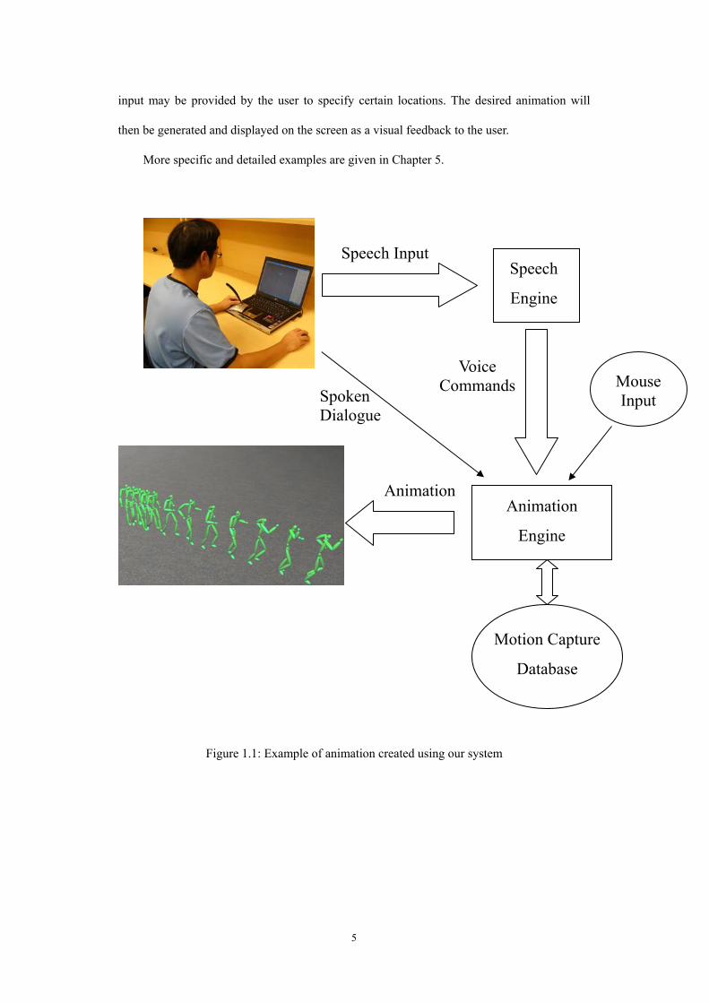
Related Documents