i Design and Implementation of a Cross Platform Real-Time Operating System and Embedded Hardware Driver Model By Christopher John Nitta B.S. (University of California, Davis) 2000 THESIS Submitted in partial satisfaction of the requirements for the degree of Master of Science in Computer Science in the OFFICE OF GRADUATE STUDIES of the UNIVERSITY OF CALIFORNIA DAVIS Approved: _____________________________ Professor Andrew Frank, Chair _____________________________ Dr. Mark Duvall _____________________________ Professor Ronald Olsson Committee in Charge 2004

Welcome message from author
This document is posted to help you gain knowledge. Please leave a comment to let me know what you think about it! Share it to your friends and learn new things together.
Transcript

i
Design and Implementation of a Cross Platform Real-Time Operating System and Embedded Hardware Driver Model
By
Christopher John Nitta B.S. (University of California, Davis) 2000
THESIS
Submitted in partial satisfaction of the requirements for the degree of
Master of Science
in
Computer Science
in the
OFFICE OF GRADUATE STUDIES
of the
UNIVERSITY OF CALIFORNIA
DAVIS
Approved:
_____________________________ Professor Andrew Frank, Chair
_____________________________ Dr. Mark Duvall
_____________________________
Professor Ronald Olsson
Committee in Charge
2004

ii
Abstract
Embedded real-time application code for embedded control systems is often developed
from the ground up. Often this produces code that couples the application to a specific
hardware platform and that must be compiled by a specific compiler. The development
of a cross-platform “Open Systems and the Corresponding Interfaces for Automotive
Electronics” (OSEK) implementation along with an abstracted driver model allows for
application code reuse across hardware platforms. Two hardware platforms, the
Motorola MPC565 and Motorola HCS12, were chosen as the initial targets to prove this
design concept. The first application of this design concept is in use as the powertrain
control software for a prototype hybrid-electric vehicle.

iii
Acknowledgments
I would like to thank Dr. Mark Duvall for his advice and friendship without it I would not
have even applied to graduate school, Professor Andrew Frank for the UC Davis HEV
Center, its creative environment is unlike any research lab I have ever seen and I believe
is without equal. I would also like to thank Professor Ronald Olsson for his guidance and
promptness in reading and editing my thesis. I would like to thank all of the members
and alumni of Team Fate who I have worked with over the past six years, words can not
describe how positive, innovative, and fun an environment you all have provided.
I must give my deepest thanks to my friends and colleagues in the Electronics lab,
without them this work would not have been possible. Thanks to Mark Alexander for all
the electronics discussions and for introducing me OSEK, Christopher Cardé for taking
on the HCS12 drivers for me, William Allan for his unparalleled CAD skills and endless
optimism, and Charnjiv “Chief” Bangar for always making sure I had the hardware I
needed.
I would like to thank my family for all their love and support. I would especially like to
thank my mother Gwen for being the strongest person I know and giving me something
which to aspire, and to my late father John for pushing me to succeed, I wished you could
have seen this. Finally, I dedicate this thesis to the memory of my grandmother, Mary for
providing me with the opportunity to go to college.

iv
Table of Contents
Table of Figures .................................................................................................................vi Table of Code Listings ......................................................................................................vii Table of Acronyms...........................................................................................................viii Chapter 1 Introduction ........................................................................................................ 1
1.1 Real-Time Operating System Selection .............................................................. 2 1.2 System Design and Initial Hardware Targets...................................................... 4 1.3 Initial Application of CPOI and ADMES ........................................................... 5 1.4 Outline................................................................................................................. 6
Chapter 2 Background......................................................................................................... 7 2.1 History of UC Davis HEV Center Controls........................................................ 7 2.2 OSEK RTOS ....................................................................................................... 9 2.3 Existing Tools ..................................................................................................... 9
2.3.1 IAR Embedded Workbench ...................................................................... 10 2.3.2 MetroWerks CodeWarrior......................................................................... 10 2.3.3 Wind River Tornado.................................................................................. 11
Chapter 3 OSEK Hardware-Independent Design.............................................................. 12 3.1 OSEK API Services .......................................................................................... 12
3.1.1 Task Management ..................................................................................... 13 3.1.2 Interrupt Processing................................................................................... 18 3.1.3 Resource Management .............................................................................. 20 3.1.4 Event Management.................................................................................... 22 3.1.5 Alarm Management................................................................................... 25 3.1.6 Operating System Execution Control........................................................ 27
3.2 Design Choices.................................................................................................. 30 3.2.1 Independent Task Stacks........................................................................... 30 3.2.2 Priority Heap ............................................................................................. 32
3.3 Deviations From the OSEK Specification ........................................................ 33 3.3.1 Addition of Mutex Functions .................................................................... 34 3.3.2 Activation of Tasks in StartupHook.......................................................... 35 3.3.3 Precision Count Functions ........................................................................ 36 3.3.4 Relaxation of TerminateTask/ChainTask Requirement............................ 38
3.4 Summary ........................................................................................................... 39 Chapter 4 OSEK Hardware Specific Design..................................................................... 40
4.1 Motorola MPC565 ............................................................................................ 40 4.1.1 Mutex Functions........................................................................................ 40 4.1.2 Idle Counter............................................................................................... 41 4.1.3 Task Functions .......................................................................................... 42 4.1.4 AlarmTickInterrupt ................................................................................... 43 4.1.5 Precision Count Functions ........................................................................ 44
4.2 Motorola HCS12 ............................................................................................... 44 4.2.1 Mutex Functions........................................................................................ 45 4.2.2 Idle Counter............................................................................................... 46 4.2.3 Task Functions .......................................................................................... 47 4.2.4 AlarmTickInterrupt ................................................................................... 48

v
4.2.5 Precision Count Functions ........................................................................ 48 4.3 Summary ........................................................................................................... 49
Chapter 5 Abstracted Driver Model for Embedded Systems............................................ 50 5.1 Introduction to ADMES.................................................................................... 51 5.2 Driver Classes ................................................................................................... 53
5.2.1 Analog To Digital Converters ................................................................... 53 5.2.2 Digital To Analog Converters ................................................................... 54 5.2.3 Digital Input / Output Ports....................................................................... 54 5.2.4 Digital Input / Output Pin.......................................................................... 55 5.2.5 Pulse Width Modulation............................................................................ 56 5.2.6 Period Measurement.................................................................................. 58 5.2.7 Counters .................................................................................................... 59 5.2.8 Queued Serial Peripheral Interfaces .......................................................... 59 5.2.9 Universal Asynchronous Receiver Transmitter Serial Communications.. 61 5.2.10 Controller Area Network........................................................................... 62
5.3 Driver Chaining................................................................................................. 65 5.4 Summary ........................................................................................................... 66
Chapter 6 Conclusions ...................................................................................................... 67 6.1 Analysis of CPOI and ADMES......................................................................... 67 6.2 Future Work ...................................................................................................... 67
6.2.1 ADMES Driver Classes ............................................................................ 68 6.2.2 System Configuration Software Tools ...................................................... 68
References ......................................................................................................................... 70 Appendix A Hardware Independent OSEK OS Source .................................................... 72 Appendix B Motorola MPC565 Hardware Dependent OSEK Source ............................. 81 Appendix C Motorola HCS12 Hardware Dependent OSEK Source ................................ 88 Appendix D Abstract Driver Model for Embedded Systems Hardware Classes.............. 91

vi
Table of Figures
Figure 1. Ideal OSEK/Driver Model Hierarchy .................................................................. 3 Figure 2. 2003 UC Davis FutureTruck PCM System Hierarchy ........................................ 5 Figure 3. Distributed Vehicle Control System Example..................................................... 8 Figure 4. Basic Task State Model ..................................................................................... 14 Figure 5. Extended Task State Model ............................................................................... 14 Figure 6. Priority Inversion Example................................................................................ 21 Figure 7. Deadlock Example............................................................................................. 21 Figure 8. Event Mechanism Example ............................................................................... 23 Figure 9. SetEvent/WaitEvent Bitwise Anding Example ................................................. 24 Figure 10. ClearEvent Math Example............................................................................... 24 Figure 11. StartOS Program Flow..................................................................................... 29 Figure 12. ShutdownOS Program Flow ............................................................................ 29 Figure 13. BCC1 Common Stack Implementation ........................................................... 31 Figure 14. Two Extended Task Stack Overrun ................................................................. 31 Figure 15. Priority Heap Insertion Example ..................................................................... 33 Figure 16. Task Calls TerminateTask ............................................................................... 38 Figure 17. TaskSkeleton Calls TerminateTask ................................................................. 38 Figure 18. CPOI/ADMES System Hierarchy ................................................................... 51 Figure 19. HwX Interface Code Example......................................................................... 52 Figure 20. PWM Example................................................................................................. 57 Figure 21. Period Measurement Example ......................................................................... 59 Figure 22. QSPI 8-bit Data Transfer Example.................................................................. 60 Figure 23. UART Serial Bit Stream.................................................................................. 62 Figure 24. Standard CAN Frame ...................................................................................... 63 Figure 25. Extended CAN Frame...................................................................................... 63 Figure 26. Driver Chaining Examples............................................................................... 66

vii
Table of Code Listings
Code Listing 1. ActivateTask Source Code ...................................................................... 72 Code Listing 2. TerminateTask Source Code ................................................................... 72 Code Listing 3. ChainTask Source Code .......................................................................... 73 Code Listing 4. Schedule Source Code............................................................................. 73 Code Listing 5. GetTaskID Source Code.......................................................................... 74 Code Listing 6. GetTaskState Source Code ...................................................................... 74 Code Listing 7. GetResource Source Code....................................................................... 74 Code Listing 8. ReleaseResource Source Code ................................................................ 75 Code Listing 9. SetEvent Source Code ............................................................................. 76 Code Listing 10. ClearEvent Source Code........................................................................ 76 Code Listing 11. GetEvent Source Code .......................................................................... 76 Code Listing 12. WaitEvent Source Code ........................................................................ 77 Code Listing 13. GetAlarmBase Source Code.................................................................. 77 Code Listing 14. GetAlarm Source Code ......................................................................... 77 Code Listing 15. SetRelAlarm Source Code..................................................................... 78 Code Listing 16. SetAbsAlarm Source Code.................................................................... 79 Code Listing 17. CancelAlarm Source Code .................................................................... 79 Code Listing 18. GetActiveApplication Source Code ...................................................... 79 Code Listing 19. StartOS Source Code............................................................................. 80 Code Listing 20. ShutdownOS Source Code .................................................................... 80 Code Listing 21. TaskSkeleton Source Code.................................................................... 80 Code Listing 22. MPC565 GetMutex Source Code.......................................................... 81 Code Listing 23. MPC565 ReleaseMutex Source Code ................................................... 81 Code Listing 24. MPC565 OSEK_INCREMENT_IDLE_COUNTER Source Code ...... 81 Code Listing 25. MPC565 SwitchContextTo Source Code.............................................. 84 Code Listing 26. MPC565 TASK_INIT_STACK Source Code ...................................... 87 Code Listing 27. MPC565 AlarmTickInterrupt Source Code........................................... 87 Code Listing 28. HCS12 GetMutex Source Code............................................................. 88 Code Listing 29. HCS12 ReleaseMutex Source Code...................................................... 88 Code Listing 30. HCS12 OSEK_INCREMENT_IDLE_COUNTER Source Code......... 88 Code Listing 31. HCS12 SwitchContextTo Source Code................................................. 89 Code Listing 32. HCS12 TASK_INIT_STACK Source Code ......................................... 89 Code Listing 33. HCS12 AlarmTickInterrupt Source Code ............................................. 90 Code Listing 34. Analog To Digital Converter Interface.................................................. 91 Code Listing 35. Digital To Analog Converter Interface.................................................. 91 Code Listing 36. Digital Input / Output Port Interface ..................................................... 92 Code Listing 37. Digital Input / Output Pin Interface....................................................... 92 Code Listing 38. Pulse Width Modulation Interface......................................................... 93 Code Listing 39. Period Measurement Interface............................................................... 93 Code Listing 40. Counter Interface ................................................................................... 93 Code Listing 41. Queued Serial Peripheral Interface (QSPI) Interface ............................ 94 Code Listing 42. UART Interface ..................................................................................... 94 Code Listing 43. Controller Area Network (CAN) Interface............................................ 95

viii
Table of Acronyms
ADC Analog to Digital Converter ADMES Abstract Driver Model for Embedded Systems API Application Programming Interface ASCII American Standard Code for Information Interchange CAN Controller Area Network CASE Computer Aided Software Engineering CCR Condition Code Register CPOI Cross-Platform OSEK Implementation CPU Central Processing Unit CPUIES Central Processing Unit Interrupt Enable State DAC Digital to Analog Converter DIO Digital Input Output ERTS Embedded Real-Time System I/O Input / Output IC Integrated Circuit ID Identifier IDE Integrated Development Environment ioctl Input Output Control Function IP Internet Protocol MISO Master Input Slave Output MOSI Master Output Slave Input MSR Machine Status Register MUTEX Mutual Exclusive Control of CPU OIL OSEK Implementation Language OS Operating System OSEK Open Systems and the Corresponding Interfaces for Automotive Electronics PCM Powertrain Control Module PWM Pulse Width Modulation QSPI Queued Serial Peripheral Interface RTOS Real Time Operating System RTR Remote Transmission Request SPI Serial Peripheral Interface TCP Transmission Control Protocol TPU Time Processing Unit UART Universal Asynchronous Receiver Transmitter VDX Vehicle Distributed eXecutive VMT Virtual Method Table

1
Chapter 1 Introduction
Embedded real-time application code is often developed from the ground up [1]. Often
this leads to code that is directly coupled to a specific hardware platform and must be
compiled by a specific compiler. The intermingling of compiler specific or hardware
specific code directly in the application code creates application code that is coupled to a
specific hardware platform or must be compiled by a specific compiler. The use of
compiler specific directives occurs because many embedded real-time operating systems
(RTOS) are proprietary and therefore directly coupled to a specific compiler vendor. The
interlacing of hardware specific code in the application occurs because embedded
systems developers often directly access hardware from the application code to gain what
they perceive as a “speed” increase. Embedded system developers do little in the way of
developing hardware drivers separate from application code. Directly accessing
hardware couples the application code with hardware specific code, and can make
changing hardware platforms or upgrading microcontrollers difficult and tedious.
Solutions exist to decouple application code from hardware specific implementations,
usually in the form of auto code generation software. Software such as MATRIXX™,
AutoCode™, and TargetLink™ auto generate code for embedded real-time systems
(ERTS) from a graphical description of the control systems. TargetLink™ auto generates
™ MATRIXX, AutoCode, and LabView are trademarks of National Instruments.
™ TargetLink is a trademark of dSpace.

2
C code from Simulink® for embedded targets. MATRIXX™ and AutoCode™ perform a
similar function as TargetLink™, but auto generates code from LabView™. These pieces
of auto code generation software, while very reliable, typically generate obfuscated C
code that is difficult to debug or modify. The use of auto code generators binds all
applications designed in them to a specific software vendor because they use proprietary
file formats to store the system model. A limited number of embedded targets are
available for these auto code generators making a hardware platform change impossible
without significant investment in time and money.
The decoupling of application code from hardware specific or compiler specific code
allows developers to change hardware platforms or compiler vendors with a minimal
amount of software rewrite. The ultimate goal of this project is to allow for the
application code reuse in ERTS across hardware platforms. Furthermore the application
code should not be restricted to a single compiler vendor. The development of a cross
platform RTOS with associated hardware drivers would allow for application code reuse
in new ERTS.
1.1 Real-Time Operating System Selection
An RTOS for an ERTS should meet the following requirements:
• Allow for preemptive multitasking; the OS must be able to preemptively switch to the highest priority task.
• Provide methods for task management; the OS must have mechanisms for activation and termination of tasks.
® Simulink is a registered trademark of MathWorks.

3
• Provide a method of task synchronization; the OS must have a mechanism to synchronize tasks.
• Provide Real-Time system response; the OS must provide a method for prioritizing the system tasks.
The “Open Systems and the Corresponding Interfaces for Automotive Electronics”
(OSEK™) OS specifies an API and allows for specific implementation to be decided by
the system designer. This in combination with meeting the previous system requirements
makes OSEK™ an ideal RTOS choice for decoupling the application code from the
hardware platform and compiler vendor. In order for application code to be decoupled
from the hardware platform, the drivers must be written to follow a defined interface.
Only the hardware specific implementation will need to be rewritten if the hardware
interfaces are well defined. Figure 1 shows the ideal system hierarchy for an embedded
system with application code that is decoupled from the hardware platform and compiler.
Figure 1. Ideal OSEK/Driver Model Hierarchy
™ OSEK is a registered trademark of Siemens AG.

4
1.2 System Design and Initial Hardware Targets
After evaluating the existing tools the decision was made to develop a Cross Platform
OSEK™ Implementation (CPOI) and the hardware drivers. The development of an
OSEK™ implementation was chosen over purchasing OSEK™ since the development
would create a body of code that could later be ported to target new hardware platforms.
The Motorola MPC565 and the Motorola HCS12 were the two hardware platforms
chosen for the first implementations of CPOI and hardware interface drivers. It was
estimated that the development for OSEK™ and associated hardware drivers would take
twelve weeks for the Motorola MPC565 platform. IAR was chosen as the development
platform for the Motorola HCS12, while MetroWerks CodeWarrior was used for the
MPC565. The use of multiple hardware platforms and multiple compilers would prove
the ability to write and test reusable application code based on the proposed OS and
hardware driver interfaces. The cross platform OS and hardware driver interfaces should
also decrease the development cycle for targeting new hardware platforms since
compatible test applications from previous platforms would be available for testing the
new hardware dependent code.
CPOI was developed for the MPC565 and HCS12 microcontroller targets. Hardware
driver interfaces were defined using the Abstracted Driver Model for Embedded Systems
(ADMES). ADMES was developed as part of this project to define a method of
hardware abstraction for ERTS. The development of CPOI and ADMES allows for
application code reuse in ERTS. Application code developed using CPOI and ADMES
can be ported to another hardware platform or compiled by another compiler without

5
being rewritten. Only hardware specific or compiler specific CPOI and ADMES code
must be rewritten for applications to be ported.
1.3 Initial Application of CPOI and ADMES
The first application developed using CPOI and ADMES was for the University of
California Davis’ 2003 FutureTruck Powertrain Control Module (PCM) [2]. The
FutureTruck PCM has three tasks:
• Powertrain Control Task (inputs driver commands and sends commands out to powertrain components)
• Inter-microcontroller Communications Task (handles Controller Area Network (CAN) communication frames and implements proprietary communication protocol stack)
• Diagnostics and Calibration Interface Task (provides an interface for vehicle designers to diagnose and calibrate the PCM operation)
The FutureTruck PCM application has been successfully controlling the FutureTruck
powertrain since June 2003. Figure 2 shows the FutureTruck PCM system hierarchy.
Figure 2. 2003 UC Davis FutureTruck PCM System Hierarchy

6
1.4 Outline
The following chapters describe the background and design of both CPOI and ADMES.
Chapter 2 explains the background information for this project and justifies the choice of
the MPC565 and HCS12 as the two test platforms. Chapter 3 describes the CPOI
hardware independent design as well as the OSEK™ Application Programming Interface
(API). Chapter 4 describes the CPOI hardware specific design for the MPC565 and
HCS12. Chapter 5 describes the Abstracted Driver Model for Embedded Systems and a
set of hardware driver interfaces. Chapter 6 concludes this work.

7
Chapter 2 Background
Multiple hardware platforms needed to be chosen for the development of the cross
platform RTOS and hardware driver interfaces. Multiple hardware platforms were also
necessary in order to prove that the concept could be applied to real world ERTS. The
University of California Davis Hybrid Electric Vehicle Center at the time of this project
was developing on two hardware platforms for use in advanced hybrid electric vehicles.
The availability of the in-vehicle multiple hardware platform ERTS made the UC Davis
HEV Center’s hybrid vehicle a perfect candidate for testing the cross platform application
code reuse. At the time of this project the UC Davis HEV Center was also in the process
of changing microcontroller platforms making it the proper time to change RTOSs and
hardware driver interfaces.
2.1 History of UC Davis HEV Center Controls
The UC Davis HEV Center develops vehicles with distributed control systems. An
example of a distributed vehicle control system similar to those seen in the UC Davis
HEVs can be seen in Figure 3. Until the year 2000 most of the source code written at the
UC Davis HEV Center consisted of infinite loops that accessed hardware directly. In
2000 the UC Davis HEV Center replaced the Z-World BL1700 microcontroller PCM
with a PC-104 microcontroller based on the x86 architecture. The UC Davis HEV Center
decided to take this opportunity to develop a set of hardware drivers for the PC-104
microcontroller as source code needed to be ported for the PCM in any case. In 2001 the
UC Davis HEV Center switched from using Microchip PICs to Motorola HC12s as the
auxiliary controllers. A set of hardware drivers for the HC12 was developed during the

8
hardware switch because of the success of the PC-104 driver set. However, the hardware
drivers were incompatible across platforms and therefore application code could not be
reused between hardware platforms. Additionally the PC-104 driver set were C++ based
and the compiler used for the HC12 only supported C.
Figure 3. Distributed Vehicle Control System Example
As of 2001 the two hardware platforms at the UC Davis HEV Center each had a set of
drivers, but none of the software written for either platform allowed for multitasking. In
2002 the UC Davis HEV Center developed an RTOS for the PC-104 PCM loosely based
on the µCOS-II RTOS [6]. During late 2002 and early 2003 the decision to change both
hardware platforms was made. The HC12 design was replaced with the Motorola HCS12
microcontroller and the PC-104 PCM was replaced with a Motorola MPC565
microcontroller. The hardware platform change required software to be rewritten and it
was decided to use this opportunity to move from the UC Davis proprietary RTOS to a

9
standardized RTOS that would support both hardware platforms. It was also decided that
the hardware driver sets should be consistent across hardware platforms.
2.2 OSEK RTOS
The “Offene Systeme und deren Schnittstellen für die Elektronik im Kraftfahrzeug” or in
English “Open Systems and the Corresponding Interfaces for Automotive Electronics”
(OSEK™) operating system is a specification for an RTOS API [3]. The OSEK™ RTOS
was started in May of 1993 as a joint project among the German automotive
manufacturers to develop an industry standard for an open-ended architecture for
distributed control units in vehicles. In 1994 the French automotive manufacturers joined
OSEK™, developing the Vehicle Distributed eXecutive (VDX) approach that is similar
to OSEK™. OSEK™ has moved from a European to an industry wide automotive
standard [4][5].
2.3 Existing Tools
OSEK™ was chosen as the RTOS for its industry wide acceptance and availability. Most
importantly the use of OSEK™ does not bind the project to a specific hardware or
compiler platform. A set of hardware driver interfaces would need to be developed to
allow for application code reuse on any embedded real-time hardware platform,
especially the HCS12 and MPC565 platforms. Obviously the RTOS and hardware
™ OSEK is a registered trademark of Siemens AG.

10
drivers would also allow for application code reuse in the case of hardware platform
upgrades and changes.
A choice of an integrated development environment (IDE) needed to be made for the
development of this project. IAR Embedded Workbench, MetroWerks CodeWarrior, and
Wind River Tornado were the three IDEs given serious thought.
2.3.1 IAR Embedded Workbench
Unfortunately IAR does not have an OSEK™ implementation for the HCS12. Third
party vendors support their own proprietary RTOSs, but no third party vendor has
OSEK™ for IAR Embedded Workbench targeting the HCS12. Furthermore, IAR does
not support the Motorola MPC565 target.
2.3.2 MetroWerks CodeWarrior
MetroWerks CodeWarrior supports both the Motorola MPC565 and the Motorola
HCS12. MetroWerks also offers OSEKturbo an OSEK™ implementation for both
hardware platforms along with a set of low-level hardware drivers for both target
platforms with a minimal configuration tool. Unfortunately the use of these drivers
would couple any application code written to the CodeWarrior compiler. A set of
hardware drivers would need to be written to allow application code reuse. It was
estimated from previous experience that six weeks would be required to develop the
hardware drivers for both platforms if two graduate students worked on the development
full time. The lead time to obtain these software tools was estimated at four weeks due in
part to University overhead.

11
2.3.3 Wind River Tornado
Wind River Tornado, like MetroWerks CodeWarrior, supports both hardware platforms
and offers OSEKWorks an OSEK™ implementation. Wind River, like MetroWerks,
offers low level hardware drivers, but like the MetroWerks drivers they would need to be
rewritten. The estimates for development time and software delivery lead time were the
same as the MetroWerks solution, ten weeks.

12
Chapter 3 OSEK Hardware-Independent Design
We designed Cross Platform OSEK™ Implementation (CPOI) to follow the OSEK™ API
Specification, but allow it to easily be ported to other hardware platforms. The majority
of the CPOI is written as hardware independent code. The CPOI hardware independent
code is similar to the hardware independent microkernel design described in [24]; it is
built on a hardware dependent nanokernel that must be written for each hardware
platform target. This design criterion was imposed so that minimal code rewrite would
be required to implement OSEK™ on another hardware platform. An effort to separate
algorithm from implementation was made during the design and development of CPOI.
The hardware independent CPOI source code can be found in the Appendix A. This
chapter encompasses the OSEK™ API description (Section 3.1), the OSEK™ API
implementation (Section 3.1), the high-level design choices (Section 3.2), and the
deviations of the CPOI from the OSEK™ standard (Section 3.3).
3.1 OSEK API Services
The OSEK™ API Services are the set of functions and macros described in the
OSEK/VDX™ Operating System Specification [3]. The OSEK™ API Services are
developed using abstracted function calls and macros that are hardware or
implementation specific. The bulk of the CPOI code has been written such that a
minimal set of functions and macros must be developed specifically for each platform.
All OSEK™ API services are grouped into six categories: task management, interrupt
processing, resource management, event management, alarm management, and execution

13
control. Each API description in this section presents the OSEK™ specification for the
specific function and then describes the actual implementation of that specification.
3.1.1 Task Management
Tasks are the framework subdivision chosen in OSEK™ to provide asynchronous
concurrent execution of code. An OSEK™ task is similar to that of a thread since, noting
that OSEK™ applications typically are compiled into a single executable, access to
global memory is possible. Each task is referenced by its unique task identifier (task ID).
The task management functions of the OSEK™ API services encompass activation,
termination, scheduling, and querying task state. OSEK™ specifies two types of tasks:
Basic and Extended. Their difference is that Basic tasks cannot call the WaitEvent API;
basic tasks must execute until termination only being preempted by higher priority tasks.
Figure 4 shows the state transition model for Basic tasks and Figure 5 shows the state
transition model for Extended tasks. Basic tasks have three possible task states:
SUSPENDED, READY, and RUNNING. Extended tasks, similar to Basic tasks, can
also incur a WAITING state. Tasks in the SUSPENDED state must be activated before
running. A READY task will run when it is the highest priority READY task. An
Extended task that is WAITING will become READY when one or more of the events
that the Extended task is waiting for is set. The only task ever in the RUNNING state is
the currently executing task.

14
running
ready
suspended
terminate
activate
preempt start
Figure 4. Basic Task State Model
running
ready
suspendedwaiting
terminate
activaterelease
wait
preempt start
Figure 5. Extended Task State Model
3.1.1.1 ActivateTask
ActivateTask activates a task from the SUSPENDED state to the READY state*. If the
task being activated is of higher priority than the activating task, the task being activated
will be put into the RUNNING state and subsequently execute. If the task being
activated is of lower priority than the activating task then the task being activated will be
placed in the READY state. The newly activated task will wait in the READY state until
it is the highest priority task of the READY and RUNNING tasks, then it will execute.
ActivateTask, shown in Code Listing 1 in Appendix A, acquires exclusive control of the
CPU by disabling interrupts through a call to GetMutex†. ActivateTask then checks the
* Note: A task may immediately transition from READY to the RUNNING state.
† Note: The use of Mutex in GetMutex and Release Mutex is from legacy CPOI code. See Section 3.3.1 for
more information on GetMutex and ReleaseMutex.

15
task to be activated for a valid task ID and a SUSPENDED state. If either the task ID is
invalid or the task is not in the SUSPENDED state the previous CPU Interrupt Enable
State (CPUIES) is restored and the appropriate error status is returned. Otherwise the
task is initialized. During task initialization the task’s events are cleared, effective
priority is reset, the stack is initialized, the task’s state is set to READY, and the task is
added to the priority heap. After the task has been initialized, Schedule is called to
accommodate a context switch if a higher priority task than the current task has entered
the READY state.
3.1.1.2 TerminateTask
TerminateTask terminates the current task by changing its state from RUNNING to
SUSPENDED. The OSEK™ standard specifies that all tasks must call either
TerminateTask or ChainTask at the end of their task code.
TerminateTask, listed in Code Listing 2, disables interrupts upon entry. If the current
task has not released all previously acquired resources, TerminateTask restores the
previous CPUIES and returns the corresponding error. The PostTaskHook is called prior
to task termination while the task state is still RUNNING. After the PostTaskHook call
the task state is changed to SUSPENDED and Schedule is called so that the proper
context switch can occur. TerminateTask will not return upon successful task
termination.

16
3.1.1.3 ChainTask
ChainTask is a combination of TerminateTask and ActivateTask. ChainTask terminates
the current task and then activates the task with the taskid parameter. Again, OSEK™
standard specifies that all tasks must call either ChainTask or TerminateTask at the end of
its task code.
ChainTask, listed in Code Listing 3, disables interrupts and then checks that the taskid
parameter is valid, the task state of taskid is SUSPENDED, and that the current task has
released all previously acquired resources. If any of the prior conditions are not met the
previous CPUIES is restored and a corresponding error status is returned. If all
conditions have been met, the task being activated is initialized and the PostTaskHook is
called. The current task state is subsequently changed to SUSPENDED and Schedule is
called. ChainTask will not return upon successful task termination.
3.1.1.4 Schedule
Schedule determines the task with the highest priority and switches context to it if the
highest priority task is not currently running. Schedule is called by ActivateTask,
TerminateTask, ChainTask, ReleaseResource, SetEvent, and WaitEvent OSEK™ API
services. It is not necessary for the OSEK™ application developer to call Schedule since
any time a task of higher priority could be ready Schedule is called. As Schedule is part
of the OSEK™ API services, precautions were taken so application developers may call
Schedule without adversely affecting the system.

17
Interrupts are disabled by Schedule through a call to GetMutex, as shown in Section
3.3.1. GetMutex and ReleaseMutex calls can be nested so, in the cases where Schedule is
called by another OSEK™ API service, there is no deadlock issue or loss of mutual
exclusion. After acquiring exclusive control of the CPU, Schedule, listed in Code Listing
4, checks that the current task has released all previously acquired resources; in such a
case the previous CPUIES is restored and the corresponding error status is returned. If
the current task is in the RUNNING state the top of the task priority heap is compared
with the current task’s priority. If the current task’s priority is lower than the top of the
heap or if the current task is not in the RUNNING state then the task on the top of the
heap is removed and the placed in the RUNNING state. If a context switch is necessary a
call to SwitchContextTo is made. SwitchContextTo is a hardware dependent function
that saves the current context and switches context to the task ID that is passed as a
parameter.
3.1.1.5 GetTaskID
GetTaskID returns the task ID of the current task. Exclusive control of the CPU is not
required during the GetTaskID call since context switches will not affect the value
returned by GetTaskID. The GetTaskID source can be viewed in Code Listing 5.
3.1.1.6 GetTaskState
GetTaskState returns the current state of the task with ID taskid. Interrupts are disabled
by GetTaskState because a context switch could change the state of the task being
queried in the middle of the line *state = TASK_STATE(taskid); in GetTaskState.
Since this line is not guaranteed to be atomic on all platforms, a exclusive CPU control is
18
used to protect *state from an invalid value. If either the taskid is not valid or state is a
NULL pointer GetTaskState will restore the previous CPUIES and return with a
corresponding error. The GetTaskState source can be seen in Code Listing 6.
3.1.2 Interrupt Processing
Interrupt processing functions control the enabling and disabling of interrupts. The
Enable/DisableAllInterrupts functions are hardware dependent since they control
interrupt processing of the microcontroller; however the Resume/SuspendAllInterrupts
functions may be implemented using standard C and calls to the
Enable/DisableAllInterrupts functions. Suspend/Resume pairs of functions can be
nested, but no other OSEK™ Service API may be called between these pairs. Another
method of suspending and resuming interrupts is available in CPOI and is discussed in
Section 3.3.1.
3.1.2.1 EnableAllInterrupts
EnableAllInterrupts enables all interrupts in the microcontroller allowing the
microcontroller to respond to hardware interrupts. EnableAllInterrupts is always
hardware specific and must be either written in assembly or with compiler specific
macros.
3.1.2.2 DisableAllInterrupts
DisableAllInterrupts disables all interrupts in the microcontroller allowing the
microcontroller to ignore all maskable hardware interrupts. DisableAllInterrupts, like
EnableAllInterrupts, is always hardware specific and must be either written in assembly
or with compiler specific macros.
19
3.1.2.3 ResumeAllInterrupts
ResumeAllInterrupts will re-enable all interrupts within the microcontroller given that it
has been called an equal number of times as SuspendAllInterrupts. If
ResumeAllInterrupts is called fewer times than SuspendAllInterrupts then the interrupts
will remain disabled. ResumeAllInterrupts, as stated earlier, can be implemented in C
using a global counter and calls to EnableAllInterrupts.
3.1.2.4 SuspendAllInterrupts
SuspendAllInterrupts disables all interrupts within the microcontroller and increments the
nesting count for Suspend/ResumeAllInterrupts. SuspendAllInterrupts as stated earlier
can be implemented in C using a global counter and a call to DisableAllInterrupts.
3.1.2.5 ResumeOSInterrupts
ResumeOSInterrupts, like ResumeAllInterrupts, will re-enable all OS interrupts within
the microcontroller given that it has been called an equal number of times as
SuspendOSInterrupts. The ResumeOSInterrupts implementation must be hardware
specific since enabling and disabling specific interrupts may not be possible on all
hardware platforms. ResumeOSInterrupts may be implemented in C like
ResumeAllInterrupts, but is platform dependent.
3.1.2.6 SuspendOSInterrupts
SuspendOSInterrupts, like SuspendAllInterrupts, disables all OS interrupts within the
microcontroller and increments the nesting count for the Suspend/ResumeOSInterrupts.
SuspendOSInterrupts, as stated above for ResumeOSInterrupts, may be implemented in
C.

20
3.1.3 Resource Management
Resources provide a mechanism to coordinate access of a shared resource by multiple
tasks. OSEK™ OS specifies the OSEK™ Priority Ceiling Protocol for resources to
prevent priority inversion and deadlocks. Priority inversion occurs when a lower-priority
task delays the execution of a higher-priority task. An example of priority inversion can
be seen in Figure 6: Task 2 prevents Task 3 from running because Task 1 has acquired a
resource for which Task 3 is waiting. Deadlock occurs when two or more tasks wait for
the impossible release of mutually locked resources, Figure 7 shows an example of
deadlock. If OSEK™ resources follow the OSEK™ Priority Ceiling Protocol priority
inversion and deadlock will be avoided. The OSEK™ Priority Ceiling Protocol states
that each resource has a statically assigned priority such that:
• The priority will be greater than or equal to the highest priority of all tasks that access it.
• The priority will be greater than or equal to any resources linked to this resource. • The priority must be lower than the lowest priority of all tasks that do not access the
resource, and which have priorities higher than the highest priority of all tasks that access the resource.
When acquiring a resource if a task’s current priority is lower than the resource’s priority
the task’s priority is raised to that of the resource. When releasing a resource the task’s
priority is reset to the priority which was dynamically assigned before acquiring the
resource.

21
Running Ready Ready
Suspended Running
Resource 1Acquired
Resource 1Requested
Resource 1Released
Task 1
Task 2
Time
Suspended WaitingTask 3 Running
Ready Running Suspended
Running
Running
Priority Inversion Task 2Preventing Task 1 FromReleasing Resource 1
Figure 6. Priority Inversion Example
Figure 7. Deadlock Example
3.1.3.1 GetResource
GetResource acquires a resource for the current task. The current task’s effective priority
is raised according to the OSEK™ Priority Ceiling Protocol.
The GetResource source can be seen in Code Listing 7, exclusive CPU control is not
necessary since the Priority Ceiling Protocol would prevent another task requesting the
resource from running. If the resource ID is invalid or if the resource has already been
acquired by another task, GetResource will return with the corresponding error state. If
another task has acquired a common resource the current task should not be running.
This condition would, however, occur if the system configuration was incorrect and the
resource priorities were improperly chosen. The higher of the resource priority and the
current task effective priority is pushed onto the current task effective priority stack. The
task ID of the current task is stored to maintain resource ownership after the current
task’s effective priority is updated.

22
3.1.3.2 ReleaseResource
ReleaseResource releases a resource so that it may be acquired by another task. The task
releasing the resource has its effective priority lowered according to the OSEK™ Priority
Ceiling Protocol.
Interrupts are disabled since the releasing the resource can change the current task’s
effective priority and scheduling may be necessary. If the resource ID is invalid or if the
resource has not been acquired by the current task ReleaseResource, seen in Code Listing
8, will return with the corresponding error state. The resource owner is set to
INVALID_TASK_ID to signal that it is again free, but the resource is not completely
released until the current task pops the effective priority from its priority stack. Schedule
is called if, after popping the effective priority from the priority stack, the current task’s
effective priority is lower than the highest on the task priority heap.
3.1.4 Event Management
OSEK™ events provide a mechanism for tasks to ‘block’, or wait for a specific event or
events to occur. Only Extended tasks can wait for events to occur; though any task can
query or set an event for another task. Events are implemented as a bitmask, with the
EventMaskType being platform dependent. An example of the ‘blocking’ event
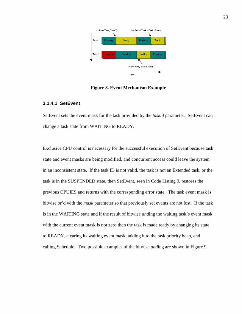
mechanism is illustrated in Figure 8.
23
Figure 8. Event Mechanism Example
3.1.4.1 SetEvent
SetEvent sets the event mask for the task provided by the taskid parameter. SetEvent can
change a task state from WAITING to READY.
Exclusive CPU control is necessary for the successful execution of SetEvent because task
state and event masks are being modified, and concurrent access could leave the system
in an inconsistent state. If the task ID is not valid, the task is not an Extended task, or the
task is in the SUSPENDED state, then SetEvent, seen in Code Listing 9, restores the
previous CPUIES and returns with the corresponding error state. The task event mask is
bitwise or’d with the mask parameter so that previously set events are not lost. If the task
is in the WAITING state and if the result of bitwise anding the waiting task’s event mask
with the current event mask is not zero then the task is made ready by changing its state
to READY, clearing its waiting event mask, adding it to the task priority heap, and
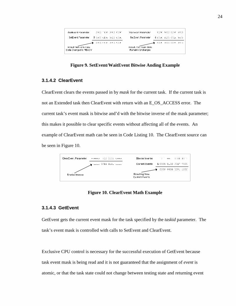
calling Schedule. Two possible examples of the bitwise anding are shown in Figure 9.
24
Figure 9. SetEvent/WaitEvent Bitwise Anding Example
3.1.4.2 ClearEvent
ClearEvent clears the events passed in by mask for the current task. If the current task is
not an Extended task then ClearEvent with return with an E_OS_ACCESS error. The
current task’s event mask is bitwise and’d with the bitwise inverse of the mask parameter;
this makes it possible to clear specific events without affecting all of the events. An
example of ClearEvent math can be seen in Code Listing 10. The ClearEvent source can
be seen in Figure 10.
Figure 10. ClearEvent Math Example
3.1.4.3 GetEvent
GetEvent gets the current event mask for the task specified by the taskid parameter. The
task’s event mask is controlled with calls to SetEvent and ClearEvent.
Exclusive CPU control is necessary for the successful execution of GetEvent because
task event mask is being read and it is not guaranteed that the assignment of event is
atomic, or that the task state could not change between testing state and returning event

25
mask. If the task ID is not valid, the task is not an Extended task, or the task is in the
SUSPENDED state then GetEvent, seen in Code Listing 11, restores the previous
CPUIES and returns with the corresponding error state.
3.1.4.4 WaitEvent
WaitEvent sets the wait event mask for the current task, and then waits until at least one
of the specified events has occurred. If one of the waiting events has previously been set
through a call to SetEvent, and has not been cleared through a call to ClearEvent, then the
task will not enter the WAITING state.
Exclusive CPU control is necessary for the successful execution of WaitEvent because
task state and event masks are being modified, and concurrent access could leave the
system in an inconsistent state. If the current task is not an Extended task, or the task has
acquired resources, WaitEvent, seen in Code Listing 12, restores the previous CPUIES
and returns with the corresponding error state. If the result of bitwise anding the task’s
waiting event mask with the event mask is not zero then WaitEvent returns; otherwise the
current task is placed in the WAITING state and Schedule is called to switch to the
highest priority ready task.
3.1.5 Alarm Management
The OSEK™ alarm mechanism provides a method for handling recurring events. Alarms
can activate a task, set an event, or call a callback function when they expire. OSEK™
alarms provide application developers a mechanism for timing, encoder measurement, or
26
any other regular countable event. Alarms may be set ‘single-shot’ or cyclically for
absolute or relative measurement.
3.1.5.1 GetAlarmBase
GetAlarmBase gets the alarm’s base info for the alarm specified by the alarmid
parameter. If the alarmid is invalid GetAlarmBase will return with an E_OS_ID error
status. The AlarmBaseType is a structure type that contains the maximum allowable tick
count, tick base for the significant unit, and minimum cycle value for the alarm. The
GetAlarmBase source can be seen in Code Listing 13.
3.1.5.2 GetAlarm
GetAlarm gets the alarm’s relative value in ticks before the alarm specified by the
alarmid parameter will expire. If the alarmid is invalid GetAlarmBase will return with
an E_OS_ID error status. A value of zero ticks means that the alarm is not active or that
the alarm has already occurred. The GetAlarm source can be seen in Code Listing 14.
3.1.5.3 SetRelAlarm
SetRelAlarm sets an alarm to occur increment ticks relative to the SetRelAlarm call. If
cycle is non-zero the alarm will recur every cycle ticks from the first expiration of the
alarm until the alarm is canceled. If alarmid is not valid, increment is greater than the
max-allowed value, cycle is non-zero and less than the minimum cycle, or the alarm is
currently active, then SetRelAlarm will return with the correct error status. The alarm’s
ticks left and cycle are set from the increment and cycle parameters. The SetRelAlarm
source can be seen in Code Listing 15.

27
3.1.5.4 SetAbsAlarm
SetAbsAlarm sets an alarm to occur at start ticks. If cycle is non-zero the alarm will
recur every cycle ticks from start until the alarm is canceled. If alarmid is not valid, start
is greater than the max-allowed value, cycle is non-zero and less than the minimum cycle,
or the alarm is currently active, then SetAbsAlarm will return with the correct error
status. The alarm’s ticks left is set equal to the current ticks minus start, where the cycle
is set from the cycle parameter. The SetAbsAlarm source can be seen in Code Listing 16.
3.1.5.5 CancelAlarm
CancelAlarm cancels the alarm so that it will not expire. CancelAlarm cancels the alarm
by setting the ticks left to zero so that there will not be a one to zero transition signaling
alarm expiration. If the alarmid is not valid or the alarm is not active, CancelAlarm will
return the corresponding error status. The CancelAlarm source can be seen in Code
Listing 17.
3.1.6 Operating System Execution Control
The OS execution control functions encompass the OS startup, shutdown, and application
mode identification.
3.1.6.1 GetActiveApplicationMode
GetActiveApplicationMode returns the application mode that was set when the OS was
started. OSDEFAULTAPPMODE is the only OSEK™ defined application mode; all
other application modes are application specific. The GetActiveApplicationMode source
can be seen in Code Listing 18.

28
3.1.6.2 StartOS
StartOS starts the OSEK™ operating system and also becomes the system Idle task. The
mode parameter sets the application mode for the OS and can be accessed by tasks and
hook functions through the calls to GetActiveApplicationMode. StartOS clears all
events, effective priority stack, and sets task state to SUSPENDED for all tasks. All
alarms are canceled and all resources are released. The resetting of all tasks, alarms, and
resources is performed in case the global system structures have not been statically
initialized properly or in the case of the OS restarting without the low level C
initialization occurring. After resetting the OS data structures the current task is set to
zero, or the Idle task. The Idle task state is set to RUNNING, the Idle Counter is reset,
and the RES_SCHEDULER resource is acquired to prevent context switches. The
StartupHook is then called where ActivateTask, SetRelAlarm, SetAbsAlarm, and
SetEvent may be called within, since the RES_SCHEDULER resource has already been
acquired by the Idle task as discussed in Section 3.3.2. After the StartupHook completes,
the OSEKStartupHWHook is called so hardware specific implementations may complete
the initialization without requiring the application developer to have knowledge of the
hardware platform. Interrupts are then enabled through a call to EnableAllInterrupts and
the RES_SCHEDULER resource is released. At this time the OS is fully functional and
context switches may occur. StartOS then enters an infinite loop that continually calls
OSEK_INCREMENT_IDLE_COUNTER, thus it becomes the Idle task. The StartOS
source can be seen in Code Listing 19. Figure 11 shows the system startup program flow.

29
Figure 11. StartOS Program Flow
3.1.6.3 ShutdownOS
ShutdownOS stops execution of the OS. Interrupts are disabled so that ShutdownOS has
exclusive control of the CPU. The ShutdownHook is called with the error parameter
passed to ShutdownOS. The OSEKShutdownHWHook is then called if the
ShutdownHook returns so that hardware specific implementations can shutdown
hardware without requiring the application developer to have knowledge of the hardware
platform. ShutdownOS enters an infinite loop if both the ShutdownHook and the
OSEKShutdownHWHook return. The ShutdownOS source can be seen in Code Listing
20. Figure 12 shows the system shutdown program flow.
Figure 12. ShutdownOS Program Flow

30
3.2 Design Choices
The design choices that were made for the development of CPOI are primarily platform
dependent. The use of independent task stacks is hardware platform dependent; there is
nothing in the hardware independent CPOI code that prevents an implementation of
integrated task stacks. The use of a heap to maintain the highest priority READY task is
also hardware platform dependent, but the macro/functions in the hardware independent
CPOI code that deal with the highest priority task contain “HEAP” in the identifier.
These two design choices discussed in this section were the two that had the greatest
impact on the system implementation; most of the other design choices made were the
obvious solution based on the OSEK™ specification.
3.2.1 Independent Task Stacks
Basic tasks can be implemented either with independent stacks or with the use of a
common stack. Basic tasks can be implemented as a function call using a common stack
since they cannot enter the waiting state; Basic tasks only release the processor if they
terminate or a higher priority task or an interrupt is scheduled. The OSEK™ BCC1
conformance class can be implemented by function calls without context switching
through stack switch. This yields a simple implementation with minimal processor and
memory overhead. Figure 13 shows an implementation of BCC1 conformance class with
a common stack. The task number is also the task priority.

31
Figure 13. BCC1 Common Stack Implementation
The OSEK™ ECC1 conformance class allows for both Extended and Basic tasks but no
multiple task activations; there may only be one task per priority. Extended tasks, unlike
Basic tasks, cannot be implemented as function calls; each Extended task must have its
own stack because there is no guarantee that they will continue execution until
termination. Figure 14 illustrates what could happen if two Extended tasks shared a
single stack.
Figure 14. Two Extended Task Stack Overrun
Activation overhead for Basic tasks can be reduced when a common stack is used. The
stack initialization that Extended tasks require is not necessary for Basic tasks using a
common stack as the task function is called directly instead of through a stack swap.
This performance improvement for Basic tasks comes at a cost of slightly lower

32
performance for all other context switches. A few extra comparison and branch
instructions are required to implement the common stack.
Both independent task stacks and a shared Basic task stack were implemented for the
MPC565. It was determined that Extended tasks were used more frequently and
therefore the common Basic task stack implementation had slightly poorer performance
that the independent stack implementation. The time for a context switch is constant in
the independent task stacks implementation; this in turn makes the job of determining the
OS overhead much easier.
3.2.2 Priority Heap
It is necessary for the OSEK™ implementation to determine which task in the READY
state has the highest priority. The determination of the highest priority task must be done
every time there is a possibility for a context switch. A simple linked list could be
searched each time. Insertions and deletions to and from the linked list require constant
time, but the overhead of determining the highest priority task requires O(n) time. For
small values of n this is not a problem, but it is desirable for CPOI to be very scalable.
While the constant insertion and deletion time is very desirable, a determination of the
highest priority task will occur at least as often as the insertion and deletions.
A heap data structure was chosen over the linked list to maintain the highest priority task.
The top of a heap can be determined in constant time and accordingly the highest priority
task can be determined in constant time. The overhead of maintaining the highest
priority task requires O(log2n) time since this is the time bound on insertions and

33
deletions to and from a heap. Figure 15 shows an example of Task 3 being inserted into
the priority heap.
Task 2Prio 7
Task 4Prio 5
Task 6Prio 3
IdleTaskPrio 0
Task 5Prio 1
Task 8Prio 4
Task 3 Addedto Heap
Task 3“Bubbled” Up
Task 2Prio 7
Task 4Prio 5
Task 6Prio 3
IdleTaskPrio 0
Task 5Prio 1
Task 8Prio 4
Task 3Prio 6
Task 2Prio 7
Task 3Prio 6
Task 6Prio 3
IdleTaskPrio 0
Task 5Prio 1
Task 8Prio 4
Task 4Prio 5
Figure 15. Priority Heap Insertion Example
3.3 Deviations From the OSEK Specification
All of the deviations from the OSEK™ specification were chosen to ease the
development of OSEK™ applications and to provide standard mechanisms for necessary
OS services not covered by the OSEK™ specification. CPOI deviations from the
OSEK™ specification allow applications written to the OSEK™ specification to function
properly. CPOI relaxes some of the requirements described in the OSEK™ specification
and provides added services. Other services were evaluated to be added to CPOI, but

34
those deviations from the OSEK™ specification chosen were done since they were
necessary for decoupling application code from the hardware specific code.
3.3.1 Addition of Mutex Functions
The OSEK™ Standard specifies the SuspendAllInterrupts function, which can provide
the application developer with mutually exclusive control of the CPU. The
SuspendAllInterrupts function’s inverse is the ResumeAllInterrupts function. The
OSEK™ standard specifies that no other OSEK™ API calls besides
SuspendAllInterrupts/ ResumeAllInterrupts pairs be allowed within a
SuspendAllInterrupts/ ResumeAllInterrupts pair. This means that there are no API
functions for the application developer to gain mutual exclusion and maintain it into an
OSEK™ API call.
The SuspendAllInterrupts/ResumeAllInterrupts functions are implemented with a single
global count variable that maintains the call nesting level. It is not necessary to maintain
individual counts for each task since it is not possible to switch to another task within a
SuspendAllInterrupts/ResumeAllInterrupts pair.
It is necessary to gain mutually exclusive control of the CPU to properly implement the
OSEK™ API functions. Being interrupted in the middle of an OSEK™ API call could
leave the system in an inconsistent state. Since the
SuspendAllInterrupts/ResumeAllInterrupts functions are implemented using globals and
context switches could occur within the pairs, it is not possible to use these functions as a

35
solution. The use of two separate mutual exclusion methods by the OSEK™
implementation designer and the application developer could lead to loss of mutual
exclusion by either party.
Two functions were added to CPOI as a solution to both the OSEK™ API
implementation and application developer’s mutual exclusion requirements. The
GetMutex and ReleaseMutex functions are used in the OSEK™ implementation and are
also provided for the application developers as a method of gaining mutual exclusion.
The GetMutex function suspends all interrupts and returns a MutexType, which is
platform dependent. A MutexType variable returned by the previous GetMutex call is
passed as parameter to the ReleaseMutex function. The ReleaseMutex function will re-
enable interrupts if interrupts were enabled prior to the GetMutex call that returned the
MutexType parameter.
The implementation of GetMutex and ReleaseMutex is platform dependent, as are
SuspendAllInterrupts and ResumeAllInterrupts. The MutexType is an integer the size of
the CPU flags register in the two platforms currently supported by CPOI. The interrupt
enable bit is typically part of the CPU flags register. Current implementations of
GetMutex save the flags register, disable interrupts and return the saved flags. The
ReleaseMutex function restores the flags register with the MutexType parameter.
3.3.2 Activation of Tasks in StartupHook
The OSEK™ standard specifies API service restrictions for task types, hooks, and
callbacks. In CPOI some of the API service restrictions have been lifted in order to

36
simplify application development. The StartupHook is only allowed to call
GetActiveApplicationMode and ShutdownOS. An interrupt must activate the first non-
”Idle” task since no Tasks can be activated in the StartupHook. An Alarm cannot even
be set to activate the first task since both of the SetXAlarm functions are not allowed in
the StartupHook.
The API service restrictions for ActivateTask, SetRelAlarm, SetAbsAlarm, and SetEvent
during the StartupHook have been lifted under CPOI. The StartOS function takes the
RES_SCHEDULER resource prior to calling StartupHook so no task switching occurs
from the StartupHook even though they have been activated. The StartOS function
acquires the RES_SCHEDULER so it can finish the system startup after the StartupHook
call. This lifting of the API service restrictions was not implemented to change the
OSEK™ specification, but to ease the burden of the OSEK™ application developer.
Those OSEK™ application developers adhering strictly to the OSEK™ specification have
the option of not using the normally restricted API services .
3.3.3 Precision Count Functions
Often it is necessary for application developers to delay for short periods of time such as
a few milliseconds. The clock interrupt source for an Alarm may not have the precision
to measure at the millisecond level or provide microsecond accuracy. Even if the clock
interrupt source can provide the required accuracy, the overhead of having a high
precision Alarm may not be desirable.

37
One common solution to the short delay problem is hand tuned countdown loops. These
loops are simple to implement, but only guarantee the minimum delay. If a task using
one of these delay loops is switched out during its waiting period and then restored it will
continue to wait until the loop has counted down, even though the delay period may have
already lapsed. Delay loops such as these are very platform dependent and will have to
be tuned for each platform. A better solution than the count down delay loop is a delay
loop that compares an expiration time with a current time.
PrecisionCount and PrecisionFrequency functions were added to provide a method for
application developers to determine time advancement precisely in a platform
independent manner. Both PrecisionCount and PrecisionFrequency return a
PrecisionCountType. The value returned by PrecisionCount is incremented at the rate
returned by PrecisionFrequency, such that every second the current PrecisionCount is
incremented PrecisionFrequency counts.
Some hardware platforms have a free running counter incrementing at the speed of the
external crystal. Hardware platforms that do not have a free running counter typically
will have some form of periodic interrupt timer or modulus down counter. If the
timer/counter has a current count register, that current count can be used to add precision
timing beyond that of the Alarm source. The current count and Alarm source may even
be the same piece of hardware.

38
3.3.4 Relaxation of TerminateTask/ChainTask Requirement
The OSEK™ standard specifies that a task must call TerminateTask or ChainTask at the
end of the task, Figure 16 illustrates program flow under OSEK™ standard. Failure to call
one of the two termination APIs can result in unknown behavior; this requirement is
relaxed in CPOI. The TaskSkeleton, seen in Code Listing 21, wraps all tasks. The
TaskSkeleton function is used as the primary entry point for all tasks. TaskSkeleton calls
the PreTaskHook and then enters the beginning of the task. TaskSkeleton prevents Tasks
that do not call one of the two termination APIs from causing unknown behavior, and
instead will terminate those tasks normally, this is shown in Figure 17. This relaxation of
the TerminateTask/ChainTask requirement was not implemented to change the OSEK™
specification, but to enhance the system reliability for beginning OSEK™ application
developers. Those OSEK™ application developers that adhere strictly to the OSEK™
specification will not notice any change in system performance.
Figure 16. Task Calls TerminateTask
Figure 17. TaskSkeleton Calls
TerminateTask

39
3.4 Summary
The development of CPOI was split into a hardware independent microkernel and a
hardware dependent nanokernel. The use of heaps and independent task stacks allow for
a scalable system with predictable task switching overhead. The deviations of CPOI
from the OSEK™ standard are enhancements that ease application development; those
applications strictly written to the OSEK™ standard will still execute properly. The
development of the CPOI nanokernels for both the MPC565 and the HCS12 is discussed
in the next chapter.

40
Chapter 4 OSEK Hardware Specific Design
As stated previously, the two hardware platforms targeted for CPOI are Motorola
embedded microcontrollers designed for automotive use. The Motorola MPC565 and the
HCS12 were the two microcontrollers chosen as targets for CPOI. These two hardware
platforms were chosen for there availability at the UC Davis HEV Center, but are not the
only two platforms that CPOI could target. Nothing prevents CPOI from targeting any
embedded microcontroller with at compiler that supports the C language.
4.1 Motorola MPC565
The Motorola MPC565 was the first platform target for the CPOI. MetroWerks
CodeWarrior for the embedded PowerPC was the compiler used for development of
MPC565 target. The Motorola MPC565, the successor to the Motorola MPC555, is an
automotive grade microcontroller implementing the PowerPC instruction standard, a
megabyte for FLASH memory, and advanced peripheral set such as Time Processing
Units (TPU). The hardware dependent source code for the MPC565 implementation of
CPOI can be seen in Appendix B. This chapter describes the MPC565 hardware
dependent implementation of the CPOI subfunctions.
4.1.1 Mutex Functions
The GetMutex and ReleaseMutex functions are implemented for the MPC565 using
inline assembly. The MutexType for the MPC565 target is a 32-bit integer since the
Machine State Register (MSR) is 32-bits wide. The importance of the MSR will be
shown the following two subsections.

41
4.1.1.1 GetMutex
The GetMutex function moves the MSR into the return register, and then disables
interrupts by clearing the EE bit in the MSR. By returning the previous MSR value the
application developer can restore the previous machine state whether interrupts were
enabled or disabled. The GetMutex source code for the MPC565 can be seen in Code
Listing 22.
4.1.1.2 ReleaseMutex
ReleaseMutex is implemented by restoring the MSR with the mutex parameter. This
restores the previous machine state. The ReleaseMutex source code for the MPC565 can
be seen in Code Listing 23.
4.1.2 Idle Counter
The OSEKIdleCounter variable is constantly incremented while the Idle Task is running.
Application developers can determine approximately how much free processing time is
still available by calling the OSEK_IDLE_PERCENT function. The Idle Counter
functions are a useful tool to determine system load, and if more time is available for
increased system responsibilities.
4.1.2.1 OSEK_RESET_IDLE_COUNTER
OSEK_RESET_IDLE_COUNTER resets the OSEKIdleCounter and the
OSEKIdlePercent variables to zero.

42
4.1.2.2 OSEK_INCREMENT_IDLE_COUNTER
The Idle Task repeatedly calls OSEK_INCREMENT_IDLE_COUNTER while it runs.
OSEK_INCREMENT_IDLE_COUNTER acquires mutual exclusion by disabling
interrupts, incrementing the OSEKIdleCounter, and then reenabling interrupts. The
OSEK_INCREMENT_IDLE_COUNTER is implemented using inline assembly for
efficiency, but could easily been implemented in C using calls to GetMutex and
ReleaseMutex. The OSEK_INCREMENT_IDLE_COUNTER source code for the
MPC565 can be seen in Code Listing 24.
4.1.2.3 OSEK_IDLE_PERCENT
OSEK_IDLE_PERCENT returns the OSEKIdlePercent value. The OSEKIdlePercent is
the average value of the OSEKIdleCounter since the OSEKIdleCounter is reset during
each call to AlarmTickInterrupt. The OSEKIdlePercent variable should use by
application developers instead of reading OSEKIdleCounter directly to accommodate
other target platform without a similar Idle Counter implementation.
4.1.3 Task Functions
The platform specific task functions are those that initialize and switch tasks, and thus
require knowledge of the specific platform.
4.1.3.1 SwitchContextTo
SwitchContextTo switches the current running task to the task that is passed in as the
taskid parameter. The MPC565 implementation of the SwitchContextTo is written in
assembly. SwitchContextTo saves all of the non-volatile registers onto the stack.
MetroWerks CodeWarrior for the embedded PowerPC uses registers r3 through r12 as

43
volatile registers and therefore do not need to be saved by the called function. After all of
the registers have been saved the current stack pointer is stored in the current task’s
global area. The stack pointer is then restored with the switch to taskid’s stack pointer.
After the registers are popped off the stack, the context has been switched. The
SwitchContextTo source code for the MPC565 can be seen in Code Listing 25.
4.1.3.2 TASK_INIT_STACK
TASK_INIT_STACK prepares a SUSPENDED task’s stack so that it can be switched to
when it is the highest priority READY task. The task stack being initialized has initial
values for the 32 general-purpose and 32 floating-point registers*. Initial values for the
other condition and status registers have been chosen such that the system has floating-
point math and interrupts enabled. The Link Register initial value, chosen so that the
return of SwitchContextTo would jump the system into the beginning of the newly
initialized task, is set to point to the TaskSkeleton. The TASK_INIT_STACK source
code for the MPC565 can be seen in Code Listing 26.
4.1.4 AlarmTickInterrupt
The real time interrupt calls AlarmTickInterrupt. This function handles the single Alarm
source and signals the expired alarms. The AlarmTickInterrupt function also updates the
OSEKIdlePercent variable so that it can be maintained at a regular interval. The
AlarmTickInterrupt function acquires the RES_SCHEDULER so that it can signal all
necessary Events and activate all necessary Tasks without being switched out. The
* Note: These initial values were chosen for debugging purposes.

44
AlarmTickInterrupt may not be switched out of since multiple tasks could be activated at
the same time, and therefore a lower priority task could be switched to before
AlarmTickInterrupt has had a chance to activate the higher priority task. The
AlarmTickInterrupt source code for the MPC565 can be seen in Code Listing 27.
4.1.5 Precision Count Functions
The PrecisionCountType is a 64-bit unsigned integer on the MPC565 implementation.
64-bit math was chosen because even with a 4MHz source for the PrecisionCount a
wraparound will only occur about every 146,135 years.
4.1.5.1 PrecisionCount
The PrecisionCount function, as described in Section 3.3.3, provides highly precise
timing capability. The MPC565 Time Base Register is used to keep the Precision Count.
The current value of the Time Base, a 64-bit free running counter incremented at the rate
of the external clock, is returned by the PrecisionCount function.
4.1.5.2 PrecisionFrequency
The PrecisionFrequency function returns the frequency of the MPC565 external clock.
This is a constant value that is dependent on the MPC565 external circuitry. The first
implementation of CPOI was on an MPC565 with an external clock of 4MHz. This
provided a PrecisionCount accurate to the nearest 250ns.
4.2 Motorola HCS12
The Motorola HCS12 is the successor to the HC12 family of microcontrollers. The
HC12 family of microcontrollers was developed for instruction set compatibility with the

45
Motorola HC11, an automotive industry standard microcontroller for many years. The
HCS12 was the second platform target for CPOI. IAR Systems Embedded Workbench
for the HC12 and HCS12 was the development environment used for the HCS12 target.
The Motorola HCS12, like the MPC565, is an automotive grade microcontroller. The
HCS12 implements an instruction set compatible with the Motorola HC11 while
incorporating 256KB of FLASH memory and 12KB of RAM. The HCS12 has an
advanced set of peripherals including analog-to-digital converters and capture compare
hardware. The hardware dependent source code for the HCS12 implementation of CPOI
can be seen in Appendix C. This section describes the HCS12 hardware dependent
implementation of the CPOI subfunctions.
4.2.1 Mutex Functions
The GetMutex and ReleaseMutex functions are implemented for the HCS12 using
assembly. The MutexType for the HCS12 target is a 16-bit integer since the Condition
Code Register (CCR) is 16-bit wide register. The importance of the CCR will be shown
the following two subsections.
4.2.1.1 GetMutex
The GetMutex function moves the CCR into the return register, and then disables
interrupts by clearing the I bit in the CCR. By returning the previous CCR value the
application developer can restore the previous machine state with a call to ReleaseMutex.
The GetMutex source code for the HCS12 can be seen in Code Listing 28.

46
4.2.1.2 ReleaseMutex
ReleaseMutex is implemented by restoring the CCR with the mutex parameter. This
restores the previous machine state. The ReleaseMutex source code for the HCS12 can
be seen in Code Listing 29.
4.2.2 Idle Counter
The OSEKIdleCounter variable gets incremented constantly while the Idle Task is
running. Application developers can determine approximately how much free processing
time is available by calling the OSEK_IDLE_PERCENT function. The Idle Counter
functions are a useful tool to determine system load, and if more time is available for
increased system responsibilities.
4.2.2.1 OSEK_RESET_IDLE_COUNTER
OSEK_RESET_IDLE_COUNTER resets the OSEKIdleCounter and the
OSEKIdlePercent variables to 0.
4.2.2.2 OSEK_INCREMENT_IDLE_COUNTER
The Idle Task repeatedly calls OSEK_INCREMENT_IDLE_COUNTER while it runs.
OSEK_INCREMENT_IDLE_COUNTER acquires mutual exclusion by disabling
interrupts, incrementing the OSEKIdleCounter, and then reenabling interrupts. The
OSEK_INCREMENT_IDLE_COUNTER is implemented in C using calls to GetMutex
and ReleaseMutex. The OSEK_INCREMENT_IDLE_COUNTER source code for the
HCS12 can be seen in Code Listing 30.

47
4.2.2.3 OSEK_IDLE_PERCENT
OSEK_IDLE_PERCENT returns the OSEKIdlePercent value. The OSEKIdlePercent is
the average value of the OSEKIdleCounter since the OSEKIdleCounter is reset during
each call to AlarmTickInterrupt. The OSEKIdlePercent variable should use by
application developers instead of reading OSEKIdleCounter directly in case another
target platform did not implement the Idle Counter in the same way.
4.2.3 Task Functions
The platform specific task functions are those that initialize and switch tasks, and thus
require knowledge of the specific platform.
4.2.3.1 SwitchContextTo
SwitchContextTo switches the current running task to the task that is passed in as a
parameter. The HCS12 implementation of the SwitchContextTo is written in assembly.
SwitchContextTo saves all of the registers onto the stack and then stores the current stack
pointer in the current tasks global area. The stack pointer is then restored with the task
that is being switched to. All the registers are popped off of the stack and the context has
been switched. The SwitchContextTo source code for the HCS12 can be seen in Code
Listing 31.
4.2.3.2 TASK_INIT_STACK
TASK_INIT_STACK prepares a SUSPENDED task’s stack so that a context switch to
the task may occur when necessary. The task stack being initialized has initial values for
the CCR, X, Y, and D registers. Unlike the MPC565, the HCS12 does not have a Link
Register and therefore an initial return subroutine location is set to TaskSkeleton for the

48
non-banked memory model. For the banked memory model version the bank location is
also placed on the stack for a return from call instruction instead of a return from
subroutine. The TaskSkeleton value was chosen so that the return of SwitchContextTo
would jump the system into the beginning of the newly initialized task. The
TASK_INIT_STACK source code for the HCS12 can be seen in Code Listing 32.
4.2.4 AlarmTickInterrupt
The real time interrupt calls AlarmTickInterrupt. This function handles the single Alarm
source and signals the expired alarms. The AlarmTickInterrupt function also updates the
OSEKIdlePercent variable so that it can be maintained at a regular interval. The
AlarmTickInterrupt function acquires the RES_SCHEDULER so that it can signal all
necessary Events and activate all necessary Tasks without being switched out of; multiple
tasks could be activated at the same time and thus a lower priority task could be switched
to before AlarmTickInterrupt has had a chance to activate the higher priority task. The
AlarmTickInterrupt source code for the HCS12 can be seen in Code Listing 33.
4.2.5 Precision Count Functions
The PrecisionCountType is a 64-bit unsigned integer on the HCS12 implementation. 64-
bit math was chosen because even with a 2.5MHz source for the PrecisionCount a
wraparound will only occur about every 233,816 years.
4.2.5.1 PrecisionCount
The PrecisionCount function, as described in Section 3.3.3, provides capability for high
precision timing. The Modulus Down-Counter is used to keep the Precision Count. The
Modulus Down-Counter is a 16-bit free running counter that is decremented at a rate

49
proportional to the external clock. When the Modulus Down-Counter reaches zero an
interrupt is generated and the upper 48-bits of the 64-bit Precision Count is incremented.
The current value of the Modulus Down-Counter is combined with the upper 48-bits of
the 64-bit Precision Count and then returned by the PrecisionCount function.
4.2.5.2 PrecisionFrequency
The PrecisionFrequency function returns the frequency at which the Precision Count is
incremented; this frequency is proportional to the HCS12 external clock. This is a
constant value that is dependent upon the HCS12 external circuitry. The first
implementation of CPOI for the HCS12 was with an external clock of 10MHz, and the
Modulus Down-Counter was decremented at 1/4th that frequency or 2.5MHz. This
provided a PrecisionCount accurate to the nearest 400ns.
4.3 Summary
The development of the CPOI nanokernel services for the MPC565 and HCS12 were
discussed in this chapter. The separation of the microkernel from the nanokernel
increases the portability of CPOI. CPOI can be ported to other platforms with
development of the ten nanokernel functions described in this chapter. The previous two
sections show that application code written for CPOI can be ported from one
microcontroller platform to another. Hardware access is the final problem to be solved in
this design, and will be discussed in the next chapter.

50
Chapter 5 Abstracted Driver Model for Embedded
Systems
Often embedded systems developers directly access hardware in application code and do
little in the way of developing hardware drivers. This behavior stems from the attitude
that the speed is required and that it is easier to work with embedded hardware in this
manner [1]. Directly accessing hardware couples the algorithm code with hardware
specific code, and can make changing hardware platforms or upgrading microcontrollers
difficult and tedious.
The ADMES was designed with the following goals in mind:
• Allow for application code reuse across hardware platforms • Small code and memory size, since the target microcontrollers could have as little as
32KB of flash and 1KB of RAM • Fast execution, since automotive embedded systems are real-time systems and can
have severe consequences if real-time performance is not met. • No runtime reconfigurability, since changes in the system that would require
reconfiguring hardware would typically also require updated firmware. The combination of CPOI with ADMES provides the ability for application code reuse in
automotive embedded systems. Figure 18 shows the CPOI with ADMES system
hierarchy.

51
Figure 18. CPOI/ADMES System Hierarchy
5.1 Introduction to ADMES
The ADMES abstracts interfaces for different hardware classes. Existing driver models
such as the Linux/Unix driver model are better suited for desktop systems, but not as well
suited for embedded systems. In automotive embedded systems hardware is initialized
and then used, but rarely needs to be disabled. Many embedded hardware systems have
more complex interfaces than can easily be controlled with read and write functions; this
leads to overuse of the ioctl function. Those embedded systems described in [24], [25],
and [26] have simpler hardware interfaces than those found in the ERTS of this project.
The fact that the networking interfaces such as TCP/IP are not fully integrated into the
Linux/Unix driver model is a further argument that it would not suit the purposes of the
ERTS of this project. The ADMES defines hardware classes and their interfaces by
specifying an “adapter pattern” for each hardware class [11]. The “adapter pattern”

52
converts the interface of a class into another interface that clients expected. This lets
classes work together that could not otherwise because of incompatible interfaces.
C was chosen as the language for the ADMES since almost all embedded compilers
support C, and very few support C++, or only support a subset of C++. The obvious
choice for the ADMES hardware interfaces would be C++ virtual classes, but the
unavailability of embedded C++ compilers removed C++ as an option. All hardware
class interfaces define a C structure that contains function pointers and a void pointer to
point to internal data. C++ classes can be simulated in C using the previously discussed
method. Macros are provided to simplify the function calls for each hardware type. An
example of a generic hardware class HwX interface can be seen in Figure 19.
The void pointer can be a dangerous programming practice since all type information has
been lost, but the alternative is to pass a pointer that needs to be recast to the internal
structure type, and therefore equally as dangerous.
Figure 19. HwX Interface Code Example
typedef struct{ void (*DInitializationFunction)(void *); void *DData; void (*DDoSomethingFunction)(void *); ... }SHwX; #define HwXInitialize(x) (x)->DInitializationFunction((x)->DData) #define HwXDoSomething(x) (x)->DDoSomethingFunction((x)->DData)

53
5.2 Driver Classes
The driver classes that have been developed for ADMES were designed to meet the needs
of an automotive PCM. The following hardware class interfaces have been defined for
ADMES: analog to digital converters, digital to analog converters, digital input / output
ports, pulse width modulation, period measurement, counters, queued serial peripheral
interfaces, universal asynchronous receiver transmitter serial ports, and Controller Area
Network interfaces. The interface header source for the ADMES hardware classes can be
seen in Appendix D.
5.2.1 Analog To Digital Converters
Analog to digital converters (ADC) sample an analog voltage and convert the value into
an integer value that is linearly proportional to the voltage. For example a 12-bit, 0 to 5V
ADC will produce a value that is equal to 4095 counts / 5V or 1 count per 1.22mV.
ADCs typically have accuracies ranging from 6 to 24 bit, minimum voltage ranges of
minus10V to 0V and maximum voltage ranges of plus 5V to 10V.
Three ADC class interfaces were defined: 8, 16, and 32-bit, since ADC accuracies do not
always align to byte boundaries. The ADC class interface header code can be seen in
Code Listing 34. The ADC interface describes three functions: AToDXInitialize,
AToDXRead, and AToDXMaxValue, where the X is 8, 16, or 32. AToDXInitialize
initializes the ADC if any initialization is necessary. AToDXRead performs an analog to
digital conversion or returns the value of the previous conversion in the case of an
interval sampling ADC. AToDXMaxValue returns the maximum value that could
possibly be returned from AToDXRead; this value is equal to 2N – 1 where N is the bit

54
accuracy of the ADC. It is important to note that N is not guaranteed to equal X, but X
must be greater than or equal to N.
5.2.2 Digital To Analog Converters
Digital to analog converters (DACs) produce an analog voltage that is linearly
proportional to the digital value provided. For example a 10-bit, 0 to 5V DAC will
produce 5V / 1023 counts, or 4.88mV per count. DACs typically have accuracies
ranging from 6 to 24 bit, and maximum voltage ranges of 2.5V to 10V.
Three DAC class interfaces were defined: 8, 16, and 32-bit, since DAC accuracies do not
always align to byte boundaries. The DAC class interface header code can be seen in
Code Listing 35. The DAC interface describes four functions: DToAXInitialize,
DToAXRead, DToAXWrite and DToAXMaxValue, where the X is 8, 16, or 32.
DToAXInitialize initializes the DAC if any initialization is necessary. DToAXRead
returns the value the previously written to the DAC. DToAXWrite makes the analog
voltage appear at the output pin that corresponds to the value written. DToAXMaxValue
returns the maximum value that could possibly be written to DToAXWrite; this value is
equal to 2N – 1 where N is the bit accuracy of the DAC. It is important to note that N is
not guaranteed to equal X, but X must be greater than or equal to N.
5.2.3 Digital Input / Output Ports
Digital input/output (I/O) ports are made up of multiple pins that are set as either inputs
or outputs. Each pin has a digital value either 0 or 1. If the pin is set as an output then
the value present at the pin is dictated by the microcontroller, otherwise the pin is set to

55
high impedance and the digital value received is controlled by external circuitry. Like
the analog converter classes there are three digital input/output class interfaces defined: 8,
16, and 32-bit. A separate interface is defined for a single digital input/output pin.
The digital input/output interface defines five functions: DIOXInitialize, DIOXRead,
DIOXWrite, DIOXGetDirection, and DIOXSetDirection where X is 8, 16, or 32. The
digital input/output port class interface header code can be seen in Code Listing 36.
DIOXInitialize initializes the digital input/output port, including setting an initial port
direction and output value, if necessary. DIOXRead reads the current settings for the port
independent of the port direction; input pins read the externally set value while output
pins read back the last value set. DIOXWrite writes the value to the output port, this
function has no effect on pins set to input. DIOXGetDirection returns the pin direction
bitmask where each bit set to 1 defines an output pin and each bit set to 0 defines an
input. DIOXSetDirection sets the pin direction bitmask using the same I/O logic as the
bitmask returned by DIOXGetDirection.
5.2.4 Digital Input / Output Pin
Digital I/O pins, as described for the digital I/O ports, are set as either inputs or outputs.
Each pin has a digital value either 0 or 1; if the pin is set as an output then the value
present at the pin is dictated by the microcontroller, otherwise the pin is set to high
impedance and the digital value is controlled by external circuitry.
The digital input/output pin interface defines seven functions: DIOPinInitialize,
DIOPinGet, DIOPinSet, DIOPinClear, DIOPinToggle, DIOPinGetDirection, and

56
DIOPinSetDirection. The digital I/O pin class interface header code can be seen in Code
Listing 37. DIOPinInitialize initializes the digital I/O pin, including setting an initial pin
direction and output value, if necessary. DIOPinGet reads the current setting for the pin
independent of the port direction; if the pin is set to input it reads the externally set value
while if the pin is set to output it reads back the last value set. DIOPinSet sets the value
of the pin to logic 1 if the pin is set to output. DIOPinClear sets the value of the pin to
logic 0 if the pin is set to output. DIOPinToggle sets the value of the pin to the opposite
logic value prior to the function call if the pin is set to output. DIOPinSet, DIOPinClear,
and DIOPinToggle functions have no effect if the pin is set to input.
DIOPinGetDirection returns the pin direction where 1 means output and 0 means input.
DIOPinSetDirection sets the pin direction using the same logic as DIOPinGetDirection.
5.2.5 Pulse Width Modulation
Pulse width modulation (PWM) is modulation where the pulse duration is varied for
control. PWM parameters include the duty cycle and the switching frequency. The duty
cycle is the proportion of time the signal is high versus low, and the switching frequency
is the frequency at which the beginning and end of a cycle are marked. PWM hardware
is often used to control loads such as fans and DC motors. PWM hardware can also be
used for variable frequency output, where the duty cycle is always set to 50%.
Three PWM class interfaces were defined: 8, 16, and 32-bit. The PWM class interface
header code can be seen in Code Listing 38. The PWM interface describes seven
functions: PWMXInitialize, PWMXPulse, PWMXPeriod, PWMXPulsePeriod,
PWMXBaseFrequency, PWMXEnable, and PWMXDisable, where the X is 8, 16, or 32.

57
PWMXInitialize initializes the PWM hardware if any initialization is necessary; this will
likely include setting an initial period. PWMXPulse sets the number of counts the PWM
signal will remain high. The pulse input should be less than or equal to the previously set
period value; pulse values greater than the period value will provide a 100% duty cycle.
To adjust the switching frequency, PWMXPeriod sets the PWM period in counts based
on the base frequency. Period values of less than two counts will result in the PWM
hardware only able to output duty cycles of 0 or 100%. PWMXPulsePeriod sets both the
pulse width and the period in a single atomic action; this function is useful when the
PWM hardware is being used as a variable frequency output. PWMXBaseFrequency
returns a 32-bit unsigned integer that is equal to the frequency at which counts are
incremented; this base frequency is necessary so that the proper pulse and period values
can be calculated independent of hardware. A 32-bit value was chosen for the base
frequency since it is highly unlikely that automotive embedded hardware will approach
4GHz running speeds. PWMXEnable and PWMXDisable functions were provided as a
simple way to enable and disable the PWM output, and it should be noted that this could
have been achieved by setting a pulse of zero. Figure 20 shows an example of PWM
with a period of eighteen counts and a pulse of fourteen counts.
Figure 20. PWM Example

58
5.2.6 Period Measurement
Period measurement measures either the high, low, entire, or multiple periods of an input
signal. Speeds are typically measured using period measurement in automotive
powertrain and vehicle embedded electronics. Inductive or magnetic pickups provide
pulses that can be used to calculate speed.
The period measurement class interfaces currently defined is for 16, 32, and 64-bit. The
period measurement class interface header code can be seen in Code Listing 39. The
period measurement interface describes four functions: PeriodXInitialize, PeriodXGet,
PeriodXBaseFrequency, and PeriodXFreshData where X is 16, 32, or 64.
PeriodXInitialize initializes the period measurement hardware so that it will measure the
correct type of period. PeriodXGet returns the number of counts at the base frequency
was measured during the last period. The PeriodXBaseFrequency function returns a 32-
bit unsigned integer that is equal to the frequency at which counts are incremented by the
period measurement hardware. Like the PWM interface, a 32-bit value was chosen for
the base frequency since it is highly unlikely that automotive embedded hardware will
approach 4GHz running speeds. PeriodXFreshData returns a non-zero value if the value
returned by PeriodXGet will be a new value; this is important so a long period is not
mistaken for the previous period duration. Figure 21 shows an example of a period
measurement which would return a value of eighteen.

59
Figure 21. Period Measurement Example
5.2.7 Counters
Counters count events that occur at frequencies higher than can be obtained by software
counters. Counters can be used to count such events as drive shaft rotations, which in
automotive applications can be directly correlated to distance traveled.
The counter class interfaces currently defined are 32 and 64-bit. The counter class
interface header code can be seen in Code Listing 40. The counter interface describes
three functions: CounterXInitialize, CounterXCount, and CounterXCumulativeCount
where X is 32 or 64. CounterXInitialize initializes the counter hardware. CounterXCount
returns the count since the previous call to CounterXCount. CounterXCumulativeCount
returns the total count since the initialization of the counter hardware.
5.2.8 Queued Serial Peripheral Interfaces
Queued Serial Peripheral Interfaces (QSPIs) are serial interfaces primarily designed for
inter-chip communication in embedded systems. SPI is a synchronized serial interface
with three signals: a Master Output Slave Input (MOSI), Master Input Slave Output
(MISO), and a serial clock. Typically a chip select signal accompanies all SPI slave
devices. The master uses chip select lines so that a single SPI host port can service

60
multiple SPI slave devices. SPI allows for simultaneous read/write transactions. The
QSPI class interface handles the queuing of data transactions and the chip select line. A
separate QSPI device will be required for each external slave SPI device. An example of
two 8-bit SPI data transfers is illustrated in Figure 22.
Figure 22. QSPI 8-bit Data Transfer Example
The QSPI class interfaces currently defined are for 8 and 16-bit. The QSPI class interface
header code can be seen in Code Listing 41. Class interfaces of 32-bit or larger were not
implemented since data transfers can be performed using either the 8 or 16-bit QSPI in
the hold chip select mode, and the typical data transfer size for SPI slave devices is either
8 or 16-bits in size. The QSPI interface describes five functions: QueuedSPIXInitialize,
QueuedSPIXRead, QueuedSPIXWrite, QueuedSPIXBlocking, and
QueuedSPIXChipSelect. QueuedSPIXInitialize initializes the QSPI hardware if any
initialization is necessary, such as initialization of software queues. QueuedSPIXRead
performs an SPI read/write transaction, since data must be written out during the read
transaction. QueuedSPIXRead requires four parameters: datain, dataout, length, and
eventmask. The datain parameter is a pointer to the beginning of an array where read
data will be placed, while dataout is a pointer to the beginning of data to be written out.

61
Both datain and dataout point to arrays of size length. The eventmask parameter is an
OSEK EventMaskType that defines the event to be set when the transaction has
completed. QueuedSPIXWrite is identical to QueuedSPIXRead except that it does not
have the datain parameter; all the SPI data read in during the QueuedSPIXWrite is
ignored. QueuedSPIXBlocking sets the QSPI device into blocking or non-blocking
mode. If the QSPI device is in blocking mode calls to QueuedSPIXRead and
QueuedSPIXWrite will block until the transaction has completed. If the QSPI device is
in non-blocking mode calls to QueuedSPIXRead and QueuedSPIXWrite will return
immediately and the event defined by the eventmask parameter will be set when the
transaction has completed. QueuedSPIXChipSelect sets the chip select mode for the
QSPI device. If the QSPI chip select mode is set to hold, then the chip select will be held
active until the entire read/write transaction has completed; otherwise the chip select line
will be brought to inactive between each data unit transaction.
5.2.9 Universal Asynchronous Receiver Transmitter Serial
Communications
The Universal Asynchronous Receiver Transmitter (UART) Serial Communications
device is a serial port that allows for full duplex communication. The UART Serial
Communication device defined follows the electrical and communication byte format of
RS232, but does not require the Request To Send, Clear To Send, Data Set Ready, and
Data Terminal Ready signals. Furthermore communication data rates may exceed 19,200
bps. Figure 23 shows two bytes being transferred via a UART.

62
Figure 23. UART Serial Bit Stream
The UART Serial Communications class interface defines four functions:
UARTInitialize, UARTRead, UARTWrite, and UARTBlocking. The UART Serial
Communications class interface header code can be seen in Code Listing 42.
UARTInitialize initializes the UART hardware and any associated software queues.
UARTRead reads in length bytes into the array pointed to by datain and will signal the
event eventmask when completed. UARTWrite writes length bytes out starting at the
byte pointed to by dataout and then signals the event eventmask when completed.
UARTBlocking sets the blocking mode for UART. If the UART is in blocking mode,
calls to UARTRead and UARTWrite will not return until the data transfer has completed.
If the UART is in non-blocking mode, calls to UARTRead and UARTWrite will return
immediately and the event eventmask will be signaled when the data transfer has
completed.
5.2.10 Controller Area Network
Controller Area Network (CAN) is a serial communications protocol that is designed for
automotive and industrial applications [23]. CAN supports distributed real time control
systems with bit rates up to 1Mbps. Real time support is possible because the CAN
protocol specifies a collision resolution scheme without data or time loss. CAN
specification 2.0 allows for two data frame types: standard and extended frames.

63
Standard data frames have eleven bit identifiers and zero to eight bytes of data. Extended
data frames added with the 2.0 specification of CAN have twenty nine bit identifiers and
like standard data frames zero to eight bytes of data. The Standard CAN frame and
Extended CAN frame layouts can be seen in Figure 24 and Figure 25 respectively.
Unlike many other networking technologies, CAN frames do not specify a source or
destination fields, but instead leave that for the higher layer protocols developer to handle
from the identifier. Since CAN interfaces lack an address, masking of the identifier
provides hardware level filtering. Typically the filtering incorporates a filter identifier
and a “care/don’t care” bitmask.
Figure 24. Standard CAN Frame
Figure 25. Extended CAN Frame
The CAN class interface defines three structures: SCANFrame, SCANPort, and
SCANObject. The CAN class interface header code can be seen in Code Listing 43. The
SCANFrame is the data structure used by both the SCANPort and the SCANObject

64
interfaces. The SCANPort is the CAN interface and has six functions associated with it:
CANInitialize, CANRead, CANWrite, CANGlobalMask, CANBlocking, and
CANCreateObject. The CANInitialize function initializes the CAN interfaces baud rate
and prepares any software queues. CANRead reads length CAN frames into the array
starting at the datain pointer. CANRead will signal the event eventmask when it has
completed. CANWrite will transmit length CAN frames starting at the CAN frame
pointed to by dataout and then signals the event eventmask when the transmission of all
frames has completed. CANGlobalMask sets the global identifier filter for received
CAN frames. All CAN frames are ignored unless the CAN frames identifier, when
bitwise anded with mask, is equal to the value of id bitwise anded with mask.
CANBlocking sets the blocking mode for the CAN port. If the CAN port is in blocking
mode then calls to CANRead and CANWrite will not return until the
transmission/reception of CAN frames has completed. If the CAN port is in non-
blocking mode then calls to CANRead and CANWrite will return immediately and the
event eventmask will be signaled when the transmission/reception of CAN frames has
completed.
CANCreateObject is used to quickly filter can frames for specific application use, the
CAN objects may be implemented in software, but often CAN hardware supports CAN
objects. CANCreateObject creates the CAN object from frame a SCANFrame, a mask,
and the rxortx parameter that sets the CAN object to be either a transmission or reception
frame. The SCANObject interface returned by CANCreateObject has three functions:

65
CANObjectInitialize, CANObjectRead, and CANObjectWrite. CANObjectInitialize
initializes any hardware that may not have already been initialized by the call to
CANCreateObject. CANObjectRead places the last CAN frame to match the CAN
object into the frame parameter, and returns a non-zero value if the frame is one that has
not been read through a previous call to CANObjectRead. CANObjectWrite writes
frame out to the CAN bus when possible. CANObjectRead and CANObjectWrite unlike
CANRead and CANWrite cannot block.
5.3 Driver Chaining
Driver chaining describes the development of a hardware class interface by using other
hardware class interfaces. Automotive controllers typically have multiple integrated
circuits (IC) external to the microcontroller; often they are ADCs or DACs connected via
QSPI. The device drivers for such external ICs would conform to an ADMES driver
class, but would also use a QSPI device to implement the driver. This means that
hardware class interfaces for external ICs can be written in a platform independent
manner.
Another possible use of driver chaining is to emulate a hardware device with other device
interfaces. An example of hardware emulation is implementing a QSPI using only digital
input/output pins; four digital input/output pins would be required for such an
implementation. A digital input could be implemented using an ADC that used a mid
value as the cut off between zero and one. A digital output could be implemented using a
DAC that sets the output values to extremes. By defining the ADMES driver classes

66
some hardware may be emulated through the use of other ADMES devices. Figure 26
shows a few examples of driver chaining.
Figure 26. Driver Chaining Examples
5.4 Summary
ADMES describes hardware interface classes for use in embedded systems. The
ADMES interfaces are adapter design patterns designed to decouple the application code
for hardware dependent software. The ADMES hardware drivers adapt hardware specific
code to an interface that is compatible with application code. ADMES hardware
interfaces are developed on top of CPOI. The use of an adapter pattern allows for driver
chaining and development of new ADMES hardware implementations using existing
ADMES interfaces. This means that ADMES hardware implementations may even be
written in a platform independent manner; this is especially true of ICs external to the
microcontroller.

67
Chapter 6 Conclusions
6.1 Analysis of CPOI and ADMES
The CPOI and ADMES initial development for the MPC565 hardware was completed
within the twelve week estimate including initial 2003 FutureTruck PCM application
code. The HCS12 development of CPOI with ADMES was completed in three weeks
after the completion of the MPC565 development. CPOI alone was ported to the HCS12
platform with less than a day of development. The CPOI and ADMES development
was completed in less time than originally estimated. The combination of CPOI with
ADMES provides the ability for application code reuse between hardware platforms in
ERTS. The development of CPOI and ADMES is considered successful since
application code built on this design is in use in a real-world application, the UC Davis
2003 FutureTruck.
6.2 Future Work
There are two obvious areas for future CPOI and ADMES work. The definition of more
ADMES driver classes and the reevaluation of the existing ADMES driver classes is one
area of possible future work. Software tools to aid in the embedded system configuration
can also be developed. Computer Aided Software Engineering (CASE) tools are
becoming widely used in the automotive industry especially in combination with
OSEK™ [27][28][29][30].

68
6.2.1 ADMES Driver Classes
The development of the existing ADMES driver classes was done for the 2003 UC Davis
FutureTruck control system but other ADMES driver classes may need to be declared.
The existing ADMES driver class interfaces may also need to be redeclared to
incorporate functionality previously overlooked in the initial interface declaration.
The ADMES driver classes are currently implemented using data structures each with all
the interface function pointers, this is a non-Virtual Method Table (VMT) object
orientated design [36]. The ADMES driver classes could be implemented using another
level of indirection and a single structure with all the interface function pointers, or in
other words a VMT design. Adding another level of indirection can save space, but this
comes at a cost of performance. For the purposes of this project the VMT design would
not save much space since few identical ADMES driver objects exist in a single system.
The limited space savings of a VMT design at this time does not justify the cost of
system performance.
6.2.2 System Configuration Software Tools
The OSEK™ Implementation Language (OIL) is a specification language to describe the
OSEK™ RTOS system configuration. Many OSEK™ implementations have software
tools that input OIL files to configure the system [27][28]. No software tool has been
written to automate the configuration of any of the CPOI implementations.
Software tools to automate the configuration of CPOI and ADMES data structures would
be the greatest addition to the existing body of work, and were originally planned if time

69
had permitted. The planned software tools would not use OIL, but would have a
graphical interface for ease of use. They would be similar to those tools described in
Chapter 1, but would only be used for system configuration, not full system development.
Ideally the software tool would input files that describe the ADMES drivers and can
output the source required for configuring the embedded system. Preferably the input
files would be structured, ASCII files so that the configuration files could be easily
modified to target new hardware platforms. In this way the software tools would not
require recompilation to target new hardware platforms.

70
References
[1] Hsiung, P., Lee, T., et al., “VERTAF: An Object-Oriented Application Framework for Embedded Real-Time Systems”, Proceedings of Fifth IEEE International Symposium on Object-Oriented Real-Time Distributed Computing, pp 322 – 329, April 2002.
[2] Allen, W., Bangar, C., Cardé C., Dalal, A., Holdener, J., Meyr, N., Nitta, C., Frank, A. "Design and Development of the 2003 UC Davis FutureTruck", presented at SAE 2004 World Congress. 2004. Detroit, MI: Society of Automotive Engineers.
[3] OSEK Group (2001), OSEK/VDX Operating System Specification 2.2, Available at: http://www.osek-vdx.org/mirror/os22.pdf.
[4] Brook, D., “Embedded Real Time Operating Systems and the OSEK Standard”, SAE 2000-01-0382, March 2000.
[5] Kiencke, U., Thierer, C., "The OSEK/VDX Standard for Automotive Applications - Current Status", SAE 2000-01-0385, March 2000.
[6] Labrosse, J., MicroC/OS-II, The Real-Time Kernel, CMP Books, Lawrence, KS 2002.
[7] Barr, M., Programming Embedded Systems in C and C++, O’Reilly, Sebastopol, CA, 1999.
[8] Andrews, G., Concurrent Programming Principles and Practices, Addison-Wesley, Menlo Park, CA, 1991.
[9] Noble, J., Weir, C., Small Memory Software Patterns for Systems with Limited Memory, Addison-Wesley, London, 2001.
[10] Cormen, T., Leisserson, C., et al., Introduction to Algorithms, MIT Press, 1990.
[11] Gamma, E., Helm, R., et al., Design Patterns Elements of Reusable Object Oriented Software, Reading, Addison-Wesley, MA, 1995.
[12] Motorola, Inc., Risc Central Processing Unit Reference Manual, February 1999, Available at: http://e-www.motorola.com/files/microcontrollers/doc/ref_manual/RCPURM.pdf.
[13] Motorola, Inc., MPC565/MPC566 User’s Manual Revision 2, September 2002, Available at: http://e-www.motorola.com/files/microcontrollers/doc/ref_manual/MPC565RM_ZIP.zip
[14] Metrowerks, CodeWarrior Development Studio for PowerPC ISA Targeting Manual, October 2002, Available at: ftp://ftp.metrowerks.com/pub/docs/Targets/EPPC_6.5/Manuals/Targeting_Embedded_PPC.pdf.
[15] Metrowerks, CodeWarrior Development Tools Assembler Reference, May 2002, Available at: ftp://ftp.metrowerks.com/pub/docs/Targets/EPPC_6.5/Manuals/Assembler_Reference.pdf.
[16] Motorola, Inc., MC9S12DP256B Device User Guide V02.14, March 2001, Available at: http://e-www.motorola.com/files/soft_dev_tools/doc/data_sheet/9S12DP256B-ZIP.zip.
[17] Motorola, Inc., CPU12 Reference Manual, 1997.
[18] Morotora, Inc., S12CPUV2 Reference Manual, July 2003, Available at: http://e-www.motorola.com/files/microcontrollers/doc/ref_manual/S12CPUV2.pdf.
[19] IAR Systems, 68HC12 Assembler, Linker, and Librarian Programming Guide, September 1997.
[20] IAR Systems, 68HC12 C Compiler Programming Guide, September 1997.
[21] IAR Systems, 68HC12 C-Spy User Guide, September 1997.
[22] IAR Systems, IAR XLINK Linker and IAR XLIB Librarian Reference Guide, October 2001.

71
[23] Bosch GmbH, “CAN Specification Version 2.0”, September 1991, Available at: http://www.can.bosch.com/docu/can2spec.pdf.
[24] Yoo S., Jerraya, A., “Introduction to Hardware Abstraction Layers for SoC”, IEEE Design, Automation and Test in Europe Conference and Exhibition, pp 336-337,2003.
[25] Stewart, D.,Volpe, R., Khosla, P., "Design of Dynamically Reconfigurable Real-Time Software Using Port-Based Objects", IEEE Transactions on Software Engineering, vol. 23, no. 12, pp 759 - 776, December 1997.
[26] Stewart, D.,"An I/O Device Driver Model and Framework for Embedded Systems", Proceedings of Middleware for Distributed Real-Time Systems Workshop, December 1997.
[27] Martin, T., “Software Architectures for OSEK/VDX Applications Using MATRIXX™ and AutoCode™”, Proceedings of IEEE International Symposium on Computer Aided Control System Design, pp 231 – 236, August 1999.
[28] Foster, N., “The Complete OSEK Development Platform: Automatic OSEK Code Generation, an OSEK Operating System and Tools Development Platform”, SAE 2000-01-2583, September 2000.
[29] Swortzel, R., “Reducing Cycle Time and Costs of Embedded Control Software Using Rapid Prototyping and Automated Code Generation and Test Tools”, SAE 981984, September 1998.
[30] Köster, L., Thomsen, T., Stracke, R., "Connecting Simulink to OSEK: Automatic Code Generation for Real-Time Operating Systems with TargetLink", SAE 2001-01-0024, March 2001.
[31] Leveille, L., Gary P., Brown J., “The Embedded Cake: A Layers Model of Embedded Systems”, SAE 2002-01-0872, March 2002.
[32] Foster N., Zorbas, A., “OSEK Communications and Network Management on CAN and J1850: Software Implementation and Configuration”, SAE 2000-01-0555, March 2000.
[33] Young, J., Boulanger, R., “Adopting Industry Standards for Control Systems Within Advanced Life Support”, SAE 2002-01-2515, July 2002.
[34] Balarin, F., Lavagno, L., “Scheduling for Embedded Real-Time Systems”, IEEE Design & Test of Computers, vol 15, issue 1, pp 71 – 82, Jan – March 1998.
[35] Foster, N., Schwab, M., “Real-Time 32-Bit Microcontroller with OSEK/VDX Operating System Support”, SAE 2000-01-1243, March 2000.
[36] Louden, K., Programming Languages Principles and Practices, PWS Publishing Company, Boston, MA, 1993.

72
Appendix A Hardware Independent OSEK OS Source
StatusType ActivateTask(TaskType taskid){ StatusType ReturnStatus; MutexType Mutex; Mutex = GetMutex(); if(OSEK_TASK_COUNT <= taskid){ ReleaseMutex(Mutex); return E_OS_ID; } if(SUSPENDED != TASK_STATE(taskid)){ ReleaseMutex(Mutex); return E_OS_LIMIT; } TASK_EVENTS_CLEAR(taskid); TASK_EFFECTIVE_PRIORITY_RESET(taskid); TASK_INIT_STACK(taskid); TASK_STATE(taskid) = READY; TASK_PRIORITY_HEAP_ADD(taskid); ReturnStatus = Schedule(); ReleaseMutex(Mutex); return ReturnStatus; }
Code Listing 1. ActivateTask Source Code
StatusType TerminateTask(void){ StatusType ReturnStatus; MutexType Mutex; Mutex = GetMutex(); if(TASK_ACQUIRED_RESOURCE_COUNT(OSEKCurrentTask)){ ReleaseMutex(Mutex); return E_OS_RESOURCE; } PostTaskHook(); TASK_STATE(OSEKCurrentTask) = SUSPENDED; ReturnStatus = Schedule(); ReleaseMutex(Mutex); return ReturnStatus; }
Code Listing 2. TerminateTask Source Code
StatusType ChainTask(TaskType taskid){ StatusType ReturnStatus; MutexType Mutex; Mutex = GetMutex(); if(OSEK_TASK_COUNT <= taskid){ ReleaseMutex(Mutex);

73
return E_OS_ID; } if(SUSPENDED != TASK_STATE(taskid)){ ReleaseMutex(Mutex); return E_OS_LIMIT; } if(TASK_ACQUIRED_RESOURCE_COUNT(OSEKCurrentTask)){ ReleaseMutex(Mutex); return E_OS_RESOURCE; } TASK_EVENTS_CLEAR(taskid); TASK_EFFECTIVE_PRIORITY_RESET(taskid); TASK_INIT_STACK(taskid); TASK_STATE(taskid) = READY; TASK_PRIORITY_HEAP_ADD(taskid); PostTaskHook(); TASK_STATE(OSEKCurrentTask) = SUSPENDED; ReturnStatus = Schedule(); ReleaseMutex(Mutex); return ReturnStatus; }
Code Listing 3. ChainTask Source Code
StatusType Schedule(void){ TaskType SwitchToTask; MutexType Mutex; Mutex = GetMutex(); if(TASK_ACQUIRED_RESOURCE_COUNT(OSEKCurrentTask)){ ReleaseMutex(Mutex); return E_OS_RESOURCE; } if(TASK_PRIORITY_HEAP_COUNT()){ SwitchToTask = TASK_PRIORITY_HEAP_TOP(); if(RUNNING == TASK_STATE(OSEKCurrentTask)){ if(TASK_EFFECTIVE_PRIORITY(SwitchToTask) < TASK_EFFECTIVE_PRIORITY(OSEKCurrentTask)){ ReleaseMutex(Mutex); return E_OK; } TASK_STATE(OSEKCurrentTask) = READY; TASK_PRIORITY_HEAP_ADD(OSEKCurrentTask); } TASK_PRIORITY_HEAP_DEL_TOP(); TASK_STATE(SwitchToTask) = RUNNING; SwitchContextTo(SwitchToTask); ReleaseMutex(Mutex); return E_OK; } ReleaseMutex(Mutex); return E_OK; }
Code Listing 4. Schedule Source Code

74
StatusType GetTaskID(TaskRefType taskid){ if(NULL == taskid){ return E_OK; } *taskid = OSEKCurrentTask; return E_OK; }
Code Listing 5. GetTaskID Source Code
StatusType GetTaskState(TaskType taskid, TaskStateRefType state){ MutexType Mutex; Mutex = GetMutex(); if(OSEK_TASK_COUNT <= taskid){ ReleaseMutex(Mutex); return E_OS_ID; } if(NULL == state){ ReleaseMutex(Mutex); return E_OK; } *state = TASK_STATE(taskid); ReleaseMutex(Mutex); return E_OK; }
Code Listing 6. GetTaskState Source Code
StatusType GetResource(ResourceType resid){ if(OSEK_RESOURCE_COUNT <= resid){ return E_OS_ID; } if(INVALID_TASK_ID != RESOURCE_TASK_ID(resid)){ return E_OS_ACCESS; } if(TASK_EFFECTIVE_PRIORITY(OSEKCurrentTask) < RESOURCE_PRIORITY(resid)){ TASK_EFFECTIVE_PRIORITY_PUSH(OSEKCurrentTask, RESOURCE_PRIORITY(resid)); } else{ TASK_EFFECTIVE_PRIORITY_PUSH(OSEKCurrentTask, TASK_EFFECTIVE_PRIORITY(OSEKCurrentTask)); } RESOURCE_TASK_ID(resid) = OSEKCurrentTask; return E_OK; }
Code Listing 7. GetResource Source Code

75
StatusType ReleaseResource(ResourceType resid){ StatusType ReturnStatus; MutexType Mutex; Mutex = GetMutex(); if(OSEK_RESOURCE_COUNT <= resid){ ReleaseMutex(Mutex); return E_OS_ID; } if(OSEKCurrentTask != RESOURCE_TASK_ID(resid)){ ReleaseMutex(Mutex); return E_OS_ACCESS; } RESOURCE_TASK_ID(resid) = INVALID_TASK_ID; TASK_EFFECTIVE_PRIORITY_POP(OSEKCurrentTask); if(TASK_EFFECTIVE_PRIORITY(OSEKCurrentTask) < TASK_PRIORITY_HEAP_TOP()){ ReturnStatus = Schedule(); ReleaseMutex(Mutex); return ReturnStatus; } ReleaseMutex(Mutex); return E_OK; }
Code Listing 8. ReleaseResource Source Code
StatusType SetEvent(TaskType taskid, EventMaskType mask){ StatusType ReturnStatus; MutexType Mutex; Mutex = GetMutex(); if(OSEK_TASK_COUNT <= taskid){ ReleaseMutex(Mutex); return E_OS_ID; } if(!TASK_EXTENDED(taskid)){ ReleaseMutex(Mutex); return E_OS_ACCESS; } if(SUSPENDED == TASK_STATE(taskid)){ ReleaseMutex(Mutex); return E_OS_STATE; } TASK_EVENTS(taskid) |= mask; if(WAITING == TASK_STATE(taskid)){ if(TASK_WAITING_EVENTS(taskid) & TASK_EVENTS(taskid)){ TASK_WAITING_EVENTS_CLEAR(taskid); TASK_STATE(taskid) = READY; TASK_PRIORITY_HEAP_ADD(taskid); ReturnStatus = Schedule(); ReleaseMutex(Mutex);

76
return ReturnStatus; } } ReleaseMutex(Mutex); return E_OK; }
Code Listing 9. SetEvent Source Code
StatusType ClearEvent(EventMaskType mask){ MutexType Mutex; Mutex = GetMutex(); if(!TASK_EXTENDED(OSEKCurrentTask)){ ReleaseMutex(Mutex); return E_OS_ACCESS; } TASK_EVENTS(OSEKCurrentTask) &= ~mask; ReleaseMutex(Mutex); return E_OK; }
Code Listing 10. ClearEvent Source Code
StatusType GetEvent(TaskType taskid, EventMaskRefType event){ MutexType Mutex; Mutex = GetMutex(); if(OSEK_TASK_COUNT <= taskid){ ReleaseMutex(Mutex); return E_OS_ID; } if(!TASK_EXTENDED(taskid)){ ReleaseMutex(Mutex); return E_OS_ACCESS; } if(SUSPENDED == TASK_STATE(taskid)){ ReleaseMutex(Mutex); return E_OS_STATE; } *event = TASK_EVENTS(taskid); ReleaseMutex(Mutex); return E_OK; }
Code Listing 11. GetEvent Source Code
StatusType WaitEvent(EventMaskType mask){ StatusType ReturnStatus; MutexType Mutex; Mutex = GetMutex(); if(!TASK_EXTENDED(OSEKCurrentTask)){

77
ReleaseMutex(Mutex); return E_OS_ACCESS; } if(TASK_ACQUIRED_RESOURCE_COUNT(OSEKCurrentTask)){ ReleaseMutex(Mutex); return E_OS_RESOURCE; } TASK_WAITING_EVENTS(OSEKCurrentTask) |= mask; if(TASK_WAITING_EVENTS(OSEKCurrentTask) & TASK_EVENTS(OSEKCurrentTask)){ TASK_WAITING_EVENTS_CLEAR(OSEKCurrentTask); ReleaseMutex(Mutex); return E_OK; } TASK_STATE(OSEKCurrentTask) = WAITING; ReturnStatus = Schedule(); ReleaseMutex(Mutex); return ReturnStatus; }
Code Listing 12. WaitEvent Source Code
StatusType GetAlarmBase(AlarmType alarmid, AlarmBaseRefType info){ MutexType Mutex; Mutex = GetMutex(); if(OSEK_ALARM_COUNT <= alarmid){ ReleaseMutex(Mutex); return E_OS_ID; } *info = ALARM_ALARM_BASE(alarmid); ReleaseMutex(Mutex); return E_OK; }
Code Listing 13. GetAlarmBase Source Code
StatusType GetAlarm(AlarmType alarmid, TickRefType tick){ MutexType Mutex; Mutex = GetMutex(); if(OSEK_ALARM_COUNT <= alarmid){ ReleaseMutex(Mutex); return E_OS_ID; } *tick = ALARM_TICKS(alarmid); ReleaseMutex(Mutex); return E_OK; }
Code Listing 14. GetAlarm Source Code

78
StatusType SetRelAlarm(AlarmType alarmid, TickType increment, TickType cycle){ MutexType Mutex; Mutex = GetMutex(); if(OSEK_ALARM_COUNT <= alarmid){ ReleaseMutex(Mutex); return E_OS_ID; } if(ALARM_ALARM_BASE(alarmid).maxallowedvalue < increment){ ReleaseMutex(Mutex); return E_OS_VALUE; } if(cycle){ if(ALARM_ALARM_BASE(alarmid).mincycle > cycle){ ReleaseMutex(Mutex); return E_OS_VALUE; } } if(ALARM_TICKS(alarmid)){ ReleaseMutex(Mutex); return E_OS_STATE; } ALARM_TICKS(alarmid) = increment; ALARM_CYCLE(alarmid) = cycle; ReleaseMutex(Mutex); return E_OK; }
Code Listing 15. SetRelAlarm Source Code
StatusType SetAbsAlarm(AlarmType alarmid, TickType start, TickType cycle){ MutexType Mutex; Mutex = GetMutex(); if(OSEK_ALARM_COUNT <= alarmid){ ReleaseMutex(Mutex); return E_OS_ID; } if(ALARM_ALARM_BASE(alarmid).maxallowedvalue < start){ ReleaseMutex(Mutex); return E_OS_VALUE; } if(cycle){ if(ALARM_ALARM_BASE(alarmid).mincycle > cycle){ ReleaseMutex(Mutex); return E_OS_VALUE; } } if(ALARM_TICKS(alarmid)){ ReleaseMutex(Mutex); return E_OS_STATE; }

79
ALARM_TICKS(alarmid) = OSEKAlarmTicks - start; ALARM_CYCLE(alarmid) = cycle; ReleaseMutex(Mutex); return E_OK; }
Code Listing 16. SetAbsAlarm Source Code
StatusType CancelAlarm(AlarmType alarmid){ MutexType Mutex; Mutex = GetMutex(); if(OSEK_ALARM_COUNT <= alarmid){ ReleaseMutex(Mutex); return E_OS_ID; } if(0 == ALARM_TICKS(alarmid)){ ReleaseMutex(Mutex); return E_OS_NOFUNC; } ALARM_TICKS(alarmid) = 0; ReleaseMutex(Mutex); return E_OK; }
Code Listing 17. CancelAlarm Source Code
AppModeType GetActiveApplicationMode(void){ return OSEKApplicationMode; }
Code Listing 18. GetActiveApplication Source Code
void StartOS(AppModeType mode){ AlarmType AlarmIndex; ResourceType ResourceIndex; OSEKApplicationMode = mode; for(OSEKCurrentTask = 1; OSEKCurrentTask < OSEK_TASK_COUNT; OSEKCurrentTask++){ TASK_EVENTS_CLEAR(OSEKCurrentTask); TASK_EFFECTIVE_PRIORITY_RESET(OSEKCurrentTask); TASK_STATE(OSEKCurrentTask) = SUSPENDED; } for(AlarmIndex = 0; AlarmIndex < OSEK_ALARM_COUNT; AlarmIndex++){ ALARM_TICKS(AlarmIndex) = 0; ALARM_CYCLE(AlarmIndex) = 0; } for(ResourceIndex = 0; ResourceIndex < OSEK_RESOURCE_COUNT; ResourceIndex++){ RESOURCE_TASK_ID(ResourceIndex) = INVALID_TASK_ID; }

80
OSEKCurrentTask = 0; TASK_PRIORITY_HEAP_CLEAR(); TASK_EVENTS_CLEAR(OSEKCurrentTask); TASK_EFFECTIVE_PRIORITY_RESET(OSEKCurrentTask); TASK_STATE(OSEKCurrentTask) = RUNNING; OSEKAlarmTicks = 0; OSEK_RESET_IDLE_COUNTER(); GetResource(RES_SCHEDULER); StartupHook(); OSEKStartupHWHook(); EnableAllInterrupts(); ReleaseResource(RES_SCHEDULER); while(1){ OSEK_INCREMENT_IDLE_COUNTER(); } }
Code Listing 19. StartOS Source Code
void ShutdownOS(StatusType error){ DisableAllInterrupts(); ShutdownHook(error); OSEKShutdownHWHook(); while(1); }
Code Listing 20. ShutdownOS Source Code
void TaskSkeleton(void){ PreTaskHook(); TASK_ENTRY_POINT(OSEKCurrentTask); TerminateTask(); }
Code Listing 21. TaskSkeleton Source Code

81
Appendix B Motorola MPC565 Hardware Dependent
OSEK Source
asm MutexType GetMutex(void){ mfmsr r3 mtspr 82, r3 }
Code Listing 22. MPC565 GetMutex Source Code
asm void ReleaseMutex(MutexType mutex){ nofralloc mtmsr r3 blr }
Code Listing 23. MPC565 ReleaseMutex Source Code
asm void OSEK_INCREMENT_IDLE_COUNTER(void){ nofralloc mtspr 82, r3 lis r4, OSEKIdleCounter@ha lwz r3, OSEKIdleCounter@l(r4) addi r3, r3, 1 stw r3, OSEKIdleCounter@l(r4) mtspr 80, r3 blr }
Code Listing 24. MPC565 OSEK_INCREMENT_IDLE_COUNTER Source Code
asm void SwitchContextTo(TaskType taskid){ nofralloc stwu rsp, -376(rsp) stw r31, 104(rsp) mfmsr r31 stw r31, 0(rsp) mtspr 82, r31 mfsrr0 r31 stw r31, 4(rsp) mfsrr1 r31 stw r31, 8(rsp) mfcr r31 stw r31, 12(rsp) mfxer r31 stw r31, 16(rsp)

82
mflr r31 stw r31, 20(rsp) mfctr r31 stw r31, 24(rsp) mfdar r31 stw r31, 28(rsp) stw r0, 32(rsp) stw r14, 36(rsp) stw r15, 40(rsp) stw r16, 44(rsp) stw r17, 48(rsp) stw r18, 52(rsp) stw r19, 56(rsp) stw r20, 60(rsp) stw r21, 64(rsp) stw r22, 68(rsp) stw r23, 72(rsp) stw r24, 76(rsp) stw r25, 80(rsp) stw r26, 84(rsp) stw r27, 88(rsp) stw r28, 92(rsp) stw r29, 96(rsp) stw r30, 100(rsp) stfd fp0, 120(rsp) mffs fp0 stfd fp0, 112(rsp) stfd fp1, 128(rsp) stfd fp2, 136(rsp) stfd fp3, 144(rsp) stfd fp4, 152(rsp) stfd fp5, 160(rsp) stfd fp6, 168(rsp) stfd fp7, 176(rsp) stfd fp8, 184(rsp) stfd fp9, 192(rsp) stfd fp10, 200(rsp) stfd fp11, 208(rsp) stfd fp12, 216(rsp) stfd fp13, 224(rsp) stfd fp14, 232(rsp) stfd fp15, 240(rsp) stfd fp16, 248(rsp) stfd fp17, 256(rsp) stfd fp18, 264(rsp) stfd fp19, 272(rsp) stfd fp20, 280(rsp) stfd fp21, 288(rsp) stfd fp22, 296(rsp) stfd fp23, 304(rsp) stfd fp24, 312(rsp) stfd fp25, 320(rsp) stfd fp26, 328(rsp) stfd fp27, 336(rsp) stfd fp28, 344(rsp) stfd fp29, 352(rsp)
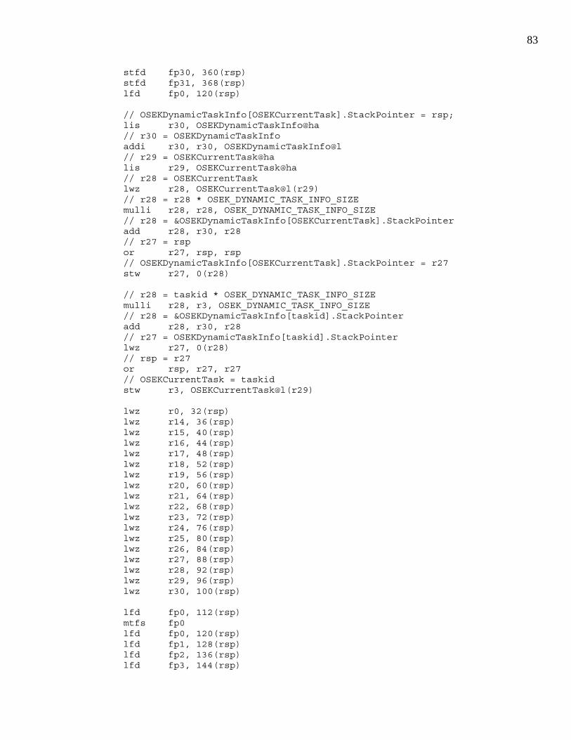
83
stfd fp30, 360(rsp) stfd fp31, 368(rsp) lfd fp0, 120(rsp) // OSEKDynamicTaskInfo[OSEKCurrentTask].StackPointer = rsp; lis r30, OSEKDynamicTaskInfo@ha // r30 = OSEKDynamicTaskInfo addi r30, r30, OSEKDynamicTaskInfo@l // r29 = OSEKCurrentTask@ha lis r29, OSEKCurrentTask@ha // r28 = OSEKCurrentTask lwz r28, OSEKCurrentTask@l(r29) // r28 = r28 * OSEK_DYNAMIC_TASK_INFO_SIZE mulli r28, r28, OSEK_DYNAMIC_TASK_INFO_SIZE // r28 = &OSEKDynamicTaskInfo[OSEKCurrentTask].StackPointer add r28, r30, r28 // r27 = rsp or r27, rsp, rsp // OSEKDynamicTaskInfo[OSEKCurrentTask].StackPointer = r27 stw r27, 0(r28) // r28 = taskid * OSEK_DYNAMIC_TASK_INFO_SIZE mulli r28, r3, OSEK_DYNAMIC_TASK_INFO_SIZE // r28 = &OSEKDynamicTaskInfo[taskid].StackPointer add r28, r30, r28 // r27 = OSEKDynamicTaskInfo[taskid].StackPointer lwz r27, 0(r28) // rsp = r27 or rsp, r27, r27 // OSEKCurrentTask = taskid stw r3, OSEKCurrentTask@l(r29) lwz r0, 32(rsp) lwz r14, 36(rsp) lwz r15, 40(rsp) lwz r16, 44(rsp) lwz r17, 48(rsp) lwz r18, 52(rsp) lwz r19, 56(rsp) lwz r20, 60(rsp) lwz r21, 64(rsp) lwz r22, 68(rsp) lwz r23, 72(rsp) lwz r24, 76(rsp) lwz r25, 80(rsp) lwz r26, 84(rsp) lwz r27, 88(rsp) lwz r28, 92(rsp) lwz r29, 96(rsp) lwz r30, 100(rsp) lfd fp0, 112(rsp) mtfs fp0 lfd fp0, 120(rsp) lfd fp1, 128(rsp) lfd fp2, 136(rsp) lfd fp3, 144(rsp)

84
lfd fp4, 152(rsp) lfd fp5, 160(rsp) lfd fp6, 168(rsp) lfd fp7, 176(rsp) lfd fp8, 184(rsp) lfd fp9, 192(rsp) lfd fp10, 200(rsp) lfd fp11, 208(rsp) lfd fp12, 216(rsp) lfd fp13, 224(rsp) lfd fp14, 232(rsp) lfd fp15, 240(rsp) lfd fp16, 248(rsp) lfd fp17, 256(rsp) lfd fp18, 264(rsp) lfd fp19, 272(rsp) lfd fp20, 280(rsp) lfd fp21, 288(rsp) lfd fp22, 296(rsp) lfd fp23, 304(rsp) lfd fp24, 312(rsp) lfd fp25, 320(rsp) lfd fp26, 328(rsp) lfd fp27, 336(rsp) lfd fp28, 344(rsp) lfd fp29, 352(rsp) lfd fp30, 360(rsp) lfd fp31, 368(rsp) lwz r31, 28(rsp) mtdar r31 lwz r31, 24(rsp) mtctr r31 lwz r31, 20(rsp) mtlr r31 lwz r31, 16(rsp) mtxer r31 lwz r31, 12(rsp) mtcr r31 lwz r31, 8(rsp) mtsrr1 r31 lwz r31, 4(rsp) mtsrr0 r31 lwz r31, 0(rsp) mtmsr r31 lwz r31, 104(rsp) addi rsp, rsp, 376 blr }
Code Listing 25. MPC565 SwitchContextTo Source Code
void TASK_INIT_STACK(TaskType taskid){ INT8U *StackTop;

85
StackTop = (INT8U *)TASK_STACK_BASE(taskid); StackTop -= sizeof(FLOAT64); *(FLOAT64 *)StackTop = (FLOAT64)31.0; StackTop -= sizeof(FLOAT64); *(FLOAT64 *)StackTop = (FLOAT64)30.0; StackTop -= sizeof(FLOAT64); *(FLOAT64 *)StackTop = (FLOAT64)29.0; StackTop -= sizeof(FLOAT64); *(FLOAT64 *)StackTop = (FLOAT64)28.0; StackTop -= sizeof(FLOAT64); *(FLOAT64 *)StackTop = (FLOAT64)27.0; StackTop -= sizeof(FLOAT64); *(FLOAT64 *)StackTop = (FLOAT64)26.0; StackTop -= sizeof(FLOAT64); *(FLOAT64 *)StackTop = (FLOAT64)25.0; StackTop -= sizeof(FLOAT64); *(FLOAT64 *)StackTop = (FLOAT64)24.0; StackTop -= sizeof(FLOAT64); *(FLOAT64 *)StackTop = (FLOAT64)23.0; StackTop -= sizeof(FLOAT64); *(FLOAT64 *)StackTop = (FLOAT64)22.0; StackTop -= sizeof(FLOAT64); *(FLOAT64 *)StackTop = (FLOAT64)21.0; StackTop -= sizeof(FLOAT64); *(FLOAT64 *)StackTop = (FLOAT64)20.0; StackTop -= sizeof(FLOAT64); *(FLOAT64 *)StackTop = (FLOAT64)19.0; StackTop -= sizeof(FLOAT64); *(FLOAT64 *)StackTop = (FLOAT64)18.0; StackTop -= sizeof(FLOAT64); *(FLOAT64 *)StackTop = (FLOAT64)17.0; StackTop -= sizeof(FLOAT64); *(FLOAT64 *)StackTop = (FLOAT64)16.0; StackTop -= sizeof(FLOAT64); *(FLOAT64 *)StackTop = (FLOAT64)15.0; StackTop -= sizeof(FLOAT64); *(FLOAT64 *)StackTop = (FLOAT64)14.0; StackTop -= sizeof(FLOAT64); *(FLOAT64 *)StackTop = (FLOAT64)13.0; StackTop -= sizeof(FLOAT64); *(FLOAT64 *)StackTop = (FLOAT64)12.0; StackTop -= sizeof(FLOAT64); *(FLOAT64 *)StackTop = (FLOAT64)11.0; StackTop -= sizeof(FLOAT64); *(FLOAT64 *)StackTop = (FLOAT64)10.0; StackTop -= sizeof(FLOAT64); *(FLOAT64 *)StackTop = (FLOAT64)9.0; StackTop -= sizeof(FLOAT64); *(FLOAT64 *)StackTop = (FLOAT64)8.0; StackTop -= sizeof(FLOAT64); *(FLOAT64 *)StackTop = (FLOAT64)7.0; StackTop -= sizeof(FLOAT64); *(FLOAT64 *)StackTop = (FLOAT64)6.0; StackTop -= sizeof(FLOAT64); *(FLOAT64 *)StackTop = (FLOAT64)5.0; StackTop -= sizeof(FLOAT64);

86
*(FLOAT64 *)StackTop = (FLOAT64)4.0; StackTop -= sizeof(FLOAT64); *(FLOAT64 *)StackTop = (FLOAT64)3.0; StackTop -= sizeof(FLOAT64); *(FLOAT64 *)StackTop = (FLOAT64)2.0; StackTop -= sizeof(FLOAT64); *(FLOAT64 *)StackTop = (FLOAT64)1.0; StackTop -= sizeof(FLOAT64); *(FLOAT64 *)StackTop = (FLOAT64)0.0; StackTop -= sizeof(FLOAT64); //FPSCR *(INT32U *)StackTop = (INT32U)0x00000000; //FPSCR StackTop -= sizeof(INT32U); StackTop -= sizeof(INT32U); *(INT32U *)StackTop = (INT32U)0x31; StackTop -= sizeof(INT32U); *(INT32U *)StackTop = (INT32U)0x30; StackTop -= sizeof(INT32U); *(INT32U *)StackTop = (INT32U)0x29; StackTop -= sizeof(INT32U); *(INT32U *)StackTop = (INT32U)0x28; StackTop -= sizeof(INT32U); *(INT32U *)StackTop = (INT32U)0x27; StackTop -= sizeof(INT32U); *(INT32U *)StackTop = (INT32U)0x26; StackTop -= sizeof(INT32U); *(INT32U *)StackTop = (INT32U)0x25; StackTop -= sizeof(INT32U); *(INT32U *)StackTop = (INT32U)0x24; StackTop -= sizeof(INT32U); *(INT32U *)StackTop = (INT32U)0x23; StackTop -= sizeof(INT32U); *(INT32U *)StackTop = (INT32U)0x22; StackTop -= sizeof(INT32U); *(INT32U *)StackTop = (INT32U)0x21; StackTop -= sizeof(INT32U); *(INT32U *)StackTop = (INT32U)0x20; StackTop -= sizeof(INT32U); *(INT32U *)StackTop = (INT32U)0x19; StackTop -= sizeof(INT32U); *(INT32U *)StackTop = (INT32U)0x18; StackTop -= sizeof(INT32U); *(INT32U *)StackTop = (INT32U)0x17; StackTop -= sizeof(INT32U); *(INT32U *)StackTop = (INT32U)0x16; StackTop -= sizeof(INT32U); *(INT32U *)StackTop = (INT32U)0x15; StackTop -= sizeof(INT32U); *(INT32U *)StackTop = (INT32U)0x14; StackTop -= sizeof(INT32U); *(INT32U *)StackTop = (INT32U)0x00; //r0 StackTop -= sizeof(INT32U); *(INT32U *)StackTop = (INT32U)0x00; //DAR StackTop -= sizeof(INT32U); *(INT32U *)StackTop = (INT32U)0x00; //CTX

87
StackTop -= sizeof(INT32U); *(INT32U *)StackTop = (INT32U)TaskSkeleton; //LR StackTop -= sizeof(INT32U); *(INT32U *)StackTop = (INT32U)0x00; //XER StackTop -= sizeof(INT32U); *(INT32U *)StackTop = (INT32U)0x00; //CR StackTop -= sizeof(INT32U); *(INT32U *)StackTop = (INT32U)0x0000B002; //SRR1 StackTop -= sizeof(INT32U); *(INT32U *)StackTop = (INT32U)TaskSkeleton; //SRR0 StackTop -= sizeof(INT32U); *(INT32U *)StackTop = (INT32U)0x0000B002; //MSR TASK_STACK(taskid) = (StackType *)StackTop; }
Code Listing 26. MPC565 TASK_INIT_STACK Source Code
void AlarmTickInterrupt(void){ AlarmType AlarmID; GetResource(RES_SCHEDULER); OSEKAlarmTicks++; OSEKIdlePercent = (OSEKIdlePercent>>1) + (OSEKIdleCounter>>1); OSEKIdleCounter = 0; for(AlarmID = 0; AlarmID < OSEK_ALARM_COUNT; AlarmID++){ if(ALARM_TICKS(AlarmID)){ ALARM_TICKS(AlarmID)--; if(0 == ALARM_TICKS(AlarmID)){ if(NULL != ALARM_CALLBACK(AlarmID)){ ALARM_CALLBACK(AlarmID)(); } else if(ALARM_EVENT_MASK(AlarmID)){ SetEvent(ALARM_TASKID(AlarmID), ALARM_EVENT_MASK(AlarmID)); } else{ ActivateTask(ALARM_TASKID(AlarmID)); } ALARM_TICKS(AlarmID) = ALARM_CYCLE(AlarmID); } } } ReleaseResource(RES_SCHEDULER); }
Code Listing 27. MPC565 AlarmTickInterrupt Source Code
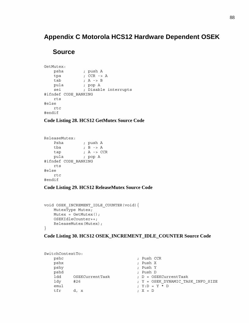
88
Appendix C Motorola HCS12 Hardware Dependent OSEK
Source
GetMutex: psha ; push A tpa ; CCR -> A tab ; A -> B pula ; pop A sei ; Disable interrupts #ifndef CODE_BANKING rts #else rtc #endif
Code Listing 28. HCS12 GetMutex Source Code
ReleaseMutex: Psha ; push A tba ; B -> A tap ; A -> CCR pula ; pop A #ifndef CODE_BANKING rts #else rtc #endif
Code Listing 29. HCS12 ReleaseMutex Source Code
void OSEK_INCREMENT_IDLE_COUNTER(void){ MutexType Mutex; Mutex = GetMutex(); OSEKIdleCounter++; ReleaseMutex(Mutex); }
Code Listing 30. HCS12 OSEK_INCREMENT_IDLE_COUNTER Source Code
SwitchContextTo: pshc ; Push CCR pshx ; Push X pshy ; Push Y pshd ; Push D ldd OSEKCurrentTask ; D = OSEKCurrentTask ldy #26 ; Y = OSEK_DYNAMIC_TASK_INFO_SIZE emul ; Y:D = Y * D tfr d, x ; X = D

89
sts OSEKDynamicTaskInfo, x ; *(OSEKDynamicTaskInfo + X) = SP ldd 0, sp ; D = id std OSEKCurrentTask ; OSEKCurrentTask = id; ldy #26 ; Y = OSEK_DYNAMIC_TASK_INFO_SIZE emul ; Y:D = Y * D tfr d, x ; X = D lds OSEKDynamicTaskInfo, x ; SP = *(OSEKDynamicTaskInfo + X) puld ; Pop D puly ; Pop Y pulx ; Pop X pulc ; Pop CCR #ifndef CODE_BANKING rts #else rtc #endif
Code Listing 31. HCS12 SwitchContextTo Source Code
void TASK_INIT_STACK(TaskType taskid){ INT8U *StackTop; StackTop = (INT8U *)TASK_STACK_BASE(taskid); StackTop -= sizeof(INT16U); *(INT16U *)StackTop = (INT16U)TaskSkeleton; #ifdef CODE_BANKING StackTop -= sizeof(INT8U); *(INT8U *)StackTop = (INT8U)(((INT32U)TaskSkeleton)>>16); #endif StackTop -= sizeof(INT8U); *(INT8U *)StackTop = (INT8U)0x40; //CCR Must set X bit StackTop -= sizeof(INT16U); *(INT16U *)StackTop = (INT16U)0x2222; //X register StackTop -= sizeof(INT16U); *(INT16U *)StackTop = (INT16U)0x1111; //Y register StackTop -= sizeof(INT16U); *(INT16U *)StackTop = (INT16U)0x0000; //D register TASK_STACK(taskid) = (StackType *)StackTop; }
Code Listing 32. HCS12 TASK_INIT_STACK Source Code
void AlarmTickInterrupt(void){ AlarmType AlarmID; GetResource(RES_SCHEDULER); OSEKAlarmTicks++; OSEKIdlePercent = (OSEKIdlePercent>>1) + (OSEKIdleCounter>>1); OSEKIdleCounter = 0; for(AlarmID = 0; AlarmID < OSEK_ALARM_COUNT; AlarmID++){ if(ALARM_TICKS(AlarmID)){ ALARM_TICKS(AlarmID)--;

90
if(0 == ALARM_TICKS(AlarmID)){ if(NULL != ALARM_CALLBACK(AlarmID)){ ALARM_CALLBACK(AlarmID)(); } else if(ALARM_EVENT_MASK(AlarmID)){ SetEvent(ALARM_TASKID(AlarmID), ALARM_EVENT_MASK(AlarmID)); } else{ ActivateTask(ALARM_TASKID(AlarmID)); } ALARM_TICKS(AlarmID) = ALARM_CYCLE(AlarmID); } } } ReleaseResource(RES_SCHEDULER); }
Code Listing 33. HCS12 AlarmTickInterrupt Source Code

91
Appendix D Abstract Driver Model for Embedded
Systems Hardware Classes
typedef struct{ void (*DInitializationFunction)(void *); void *DData; INTXU (*DReadFunction)(void *); INTXU DMaxValue; } SAToDX; #define AToDXInitialize(atod) (atod)->DInitializationFunction((atod)->DData) #define AToDXRead(atod) (atod)->DReadFunction((atod)->DData) #define AToDXMaxValue(atod) (atod)->DmaxValue
Code Listing 34. Analog To Digital Converter Interface
typedef struct{ void (*DInitializationFunction)(void *data); void *DData; INTXU (*DReadFunction)(void *data); void (*DWriteFunction)(void *data, INTXU value); INTXU DMaxValue; } SDToAX; #define DToAXInitialize(dtoa) (dtoa)->DInitializationFunction((dtoa)->DData) #define DToAXRead(dtoa) (dtoa)->DReadFunction((dtoa)->DData) #define DToAXWrite(dtoa, value) (dtoa)->DWriteFunction((dtoa)->DData, value) #define DToAXMaxValue(dtoa) (dtoa)->DMaxValue
Code Listing 35. Digital To Analog Converter Interface
typedef struct{ void (*DInitializationFunction)(void *); void *DData; INTXU (*DReadFunction)(void *); void (*DWriteFunction)(void *, INTXU); INTXU (*DGetDirectionFunction)(void *); void (*DSetDirectionFunction)(void *, INTXU); } SDIOX; #define DIOXInitialize(dio) (dio)->DInitializationFunction((dio)->DData) #define DIOXRead(dio) (dio)->DReadFunction((dio)->DData)

92
#define DIOXWrite(dio, val) (dio)->DWriteFunction((dio)->DData, (val)) #define DIOXGetDirection(dio) (dio)-> DGetDirectionFunction ((dio)->DData) #define DIOXSetDirection (dio, val) (dio)-> DSetDirectionFunction ((dio)->DData, (val))
Code Listing 36. Digital Input / Output Port Interface
typedef struct{ void (*DInitializationFunction)(void *); void *DData; INT8U (*DGetFunction)(void *); void (*DSetFunction)(void *); void (*DClearFunction)(void *); void (*DToggleFunction)(void *); INT8U (*DGetDirectionFunction)(void *); void (*DSetDirectionFunction)(void *, INT8U); } SDIOPin; #define DIOPinInitialize(dio) (dio)->DInitializationFunction((dio)->DData) #define DIOPinGet(dio) (dio)->DGetFunction((dio)->DData) #define DIOPinSet(dio) (dio)->DSetFunction((dio)->DData) #define DIOPinClear(dio) (dio)->DClearFunction((dio)->DData) #define DIOPinToggle(dio) (dio)->DToggleFunction((dio)->DData) #define DIOPinGetDirection(dio) (dio)->DGetDirectionFunction((dio)->DData) #define DIOPinSetDirection(dio, val) (dio)->DSetDirectionFunction((dio)->DData, (val))
Code Listing 37. Digital Input / Output Pin Interface
typedef struct{ void (*DInitializationFunction)(void *data); void *DData; void (*DPulseFunction)(void *data, INTXU pulse); void (*DPeriodFunction)(void *data, INTXU period); void (*DPulsePeriodFunction)(void *data, INTXU pulse, INTXU period); INT32U (*DBaseFrequencyFunction)(void *data); void (*DEnableFunction)(void *data); void (*DDisableFunction)(void *data); } SPWMX; #define PWMXInitialize(pwm) (pwm)->DInitializationFunction((pwm)->DData) #define PWMXPulse(pwm, pul) (pwm)->DPulseFunction((pwm)->DData, pul) #define PWMXPeriod(pwm, per) (pwm)->DPeriodFunction((pwm)->DData, per)

93
#define PWMXPulsePeriod(pwm, pul, per) (pwm)->DPulsePeriodFunction((pwm)->DData, pul, per) #define PWMXBaseFrequency(pwm) (pwm)->DbaseFrequencyFunction((pwm)->DData) #define PWMXEnable(pwm) (pwm)->DEnableFunction((pwm)->DData) #define PWMXDisable(pwm) (pwm)->DDisableFunction((pwm)->DData)
Code Listing 38. Pulse Width Modulation Interface
typedef struct{ void (*DInitializationFunction)(void *data); void *DData; INTXU (*DGetFunction)(void *data); INTXU (*DBaseFrequencyFunction)(void *data); INTXU (*DFreshDataFunction)(void *data); } SPeriodX; #define PeriodXInitialize(p) (p)->DInitializationFunction((p)->DData) #define PeriodXGet(p) (p)->DGetFunction((p)->DData) #define PeriodXBaseFrequency(p) (p)->DBaseFrequencyFunction((p)->DData) #define PeriodXFreshData(p) (p)->DFreshDataFunction((p)->DData)
Code Listing 39. Period Measurement Interface
typedef struct{ void (*DInitializationFunction)(void *); void *DData; INTXU (*DCountFunction)(void *); INTXU (*DCumulativeCountFunction)(void *); } SCounterX; #define CounterXInitialize(cntr) (cntr)->DInitializationFunction((cntr)->DData) #define CounterXCount(cntr) (cntr)->DCountFunction((cntr)->DData) #define CounterXCumulativeCount(cntr) (cntr)->DCumulativeCountFunction((cntr)->DData)
Code Listing 40. Counter Interface
typedef struct{ void (*DInitializationFunction)(void *); void *DData; INTXU (*DReadFunction)(void *data, INTXU *datain, INTXU *dataout, INTXU length, EventMaskType event); INTXU (*DWriteFunction)(void *data, INTXU *dataout, INTXU length, EventMaskType event); void (*DBlockingFunction)(void *data, INTXU blocking); void (*DChipSelectFunction)(void *data, INTXU hold);

94
} SQueuedSPIX; #define QueuedSPIXInitialize(spi) (spi)->DInitializationFunction((spi)->DData) #define QueuedSPIXRead(spi,datain,dataout,length,event) (spi)->DReadFunction((spi)->DData, datain, dataout, length, event) #define QueuedSPIXWrite(spi,dataout,length,event) (spi)->DWriteFunction((spi)->DData, dataout, length, event) #define QueuedSPIXBlocking(spi,block) (spi)->DBlockingFunction((spi)->DData, block) #define QueuedSPIXChipSelect(spi,hold) (spi)->DChipSelectFunction((spi)->DData, hold)
Code Listing 41. Queued Serial Peripheral Interface (QSPI) Interface
typedef struct{ void (*DInitializationFunction)(void *); void *DData; INT8U (*DReadFunction)(void *data, INT8U *datain, INT8U length, EventMaskType event); INT8U (*DWriteFunction)(void *data, INT8U *dataout, INT8U length, EventMaskType event); void (*DBlockingFunction)(void *data, INT8U blocking); } SUART; #define UARTInitialize(uart) (uart)->DInitializationFunction((uart)->DData) #define UARTRead(uart,datain,length,event) (uart)->DReadFunction((uart)->DData, datain, length, event) #define UARTWrite(uart,dataout,length,event) (uart)->DWriteFunction((uart)->DData, dataout, length, event) #define UARTBlocking(uart,block) (uart)->DBlockingFunction((uart)->DData, block)
Code Listing 42. UART Interface
typedef struct{ void (*DInitializationFunction)(void *); void *DData; INT8U (*DReadFunction)(void *data, SCANFrame *datain, INT8U length, EventMaskType event); INT8U (*DWriteFunction)(void *data, SCANFrame *dataout, INT8U length, EventMaskType event); void (*DGlobalMask)(void *data, INT32U id, INT32U mask); void (*DBlockingFunction)(void *data, INT8U blocking); void* (*DCreateObjectFunction)(void *data, SCANFrame *frame, INT32U mask, INT8U rxortx); } SCANPort; typedef struct{ void (*DInitializationFunction)(void *); void *DData; INT8U (*DReadFunction)(void *data, SCANFrame *frame); void (*DWriteFunction)(void *data, SCANFrame *frame);
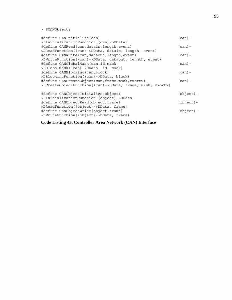
95
} SCANObject; #define CANInitialize(can) (can)->DInitializationFunction((can)->DData) #define CANRead(can,datain,length,event) (can)->DReadFunction((can)->DData, datain, length, event) #define CANWrite(can,dataout,length,event) (can)->DWriteFunction((can)->DData, dataout, length, event) #define CANGlobalMask(can,id,mask) (can)->DGlobalMask((can)->DData, id, mask) #define CANBlocking(can,block) (can)->DBlockingFunction((can)->DData, block) #define CANCreateObject(can,frame,mask,rxortx) (can)->DCreateObjectFunction((can)->DData, frame, mask, rxortx) #define CANObjectInitialize(object) (object)->DInitializationFunction((object)->DData) #define CANObjectRead(object,frame) (object)->DReadFunction((object)->DData, frame) #define CANObjectWrite(object,frame) (object)->DWriteFunction((object)->DData, frame)
Code Listing 43. Controller Area Network (CAN) Interface
Related Documents


![[shaderx7] 8.1 Cross-Platform Rendering Thread : Design and Implementation](https://static.cupdf.com/doc/110x72/558deed81a28ab2b7e8b466a/shaderx7-81-cross-platform-rendering-thread-design-and-implementation.jpg)