© 2019 JETIR March 2019, Volume 6, Issue 3 www.jetir.org (ISSN-2349-5162) JETIR1903E51 Journal of Emerging Technologies and Innovative Research (JETIR) www.jetir.org 334 DESIGN AND FABRICATION OF AUTOMATIC PIPE CUTTING MACHINE 1 B. Anbarasan, 2 K.M. Sharan, 3 T. Uday prasad, 4 B.C Vignesh 1 Assistant Professor, 2 B.E., Student, 3 B.E., Student, 4 B.E., Student 1,2,3,4 Department of Mechanical Engineering 1,2,3,4 Sri Shakthi Institute of Engineering & Technology, Coimbatore-62, Tamilnadu, India Abstract: The project “Design and fabrication of automatic pipe cutting machine” was done in SLI at SIDCO. Automatic pipe cutting machine is a device that cuts multiple pieces efficiently and comparatively it reduces the time consumed than that of ordinary cutting operations. They are used in Job and Mass production. This invention relates to pipe cutting machines used for cutting pipe into different lengths based on requirements. The primary object of the invention is to provide an improved machine of the character mentioned which is purely automatic in operation, and one which cuts the pipe in an expeditious and effective manner. This operation is usually performed by hand and is slow and laborious and involves making templates for each pipe diameter, and for each combination of pipe diameters when one of the pipes is smaller than the other. The objective of the present invention is to provide a machine for doing this work quickly and automatically and which may be set to handle pipes of various different diameters. Index Terms – Automatic pipe cutting machine, cutting operation, pipe, proximity sensor, 5inch cutter. 1. Introduction The Industry which is located in sidco named as “Sree lakshmi Engineering Works”. The main objective of our project is to perform cutting operations with the help of motor and. For a developing industry the operation performed and the parts (or) components produced should have it minimum possible production cost and then only industry runs profitability. In small-scale industry and some workshops, this increases the initial cost required, large area requirements and large number of machines is required. In our project the rod cutting operation is carried out by small arrangements and easy operations. There will be need to cut similar length of rods in industries such as construction, manufacturing etc., for this purpose industries employ two or more persons to measure the length and then cut the rod. Our project gives a solution for this there is no need to measure each and every rod for cutting. 2. Objective The main objective is to design and fabricate automatic pipe cutting machine used for valve manufacturing process. To increase productivity, faster operation, reliability and accuracy of the cutting operation. 3. Construction of automatic pipe cutting machine Fig.3.1. Automatic pipe cutting machine In this project an automatic pipe feeding mechanism and a cutting machine is used. In the pipe feeding mechanism a motor is used to feed the bar. There are four rollers mounted, in-between them the bar is feed. Two rollers shaft is connected with a chain drive and these rollers are driven rollers. The driving arrangement is placed at the bottom of the driven rollers and all the three are connected by means of chain drive. The chain drive and the other end is connected with motor arrangement. As the three drives are connected through chain every roller rotates when the motor is rotated. Thus, pipe is feed with the help of the rollers. A stopper with proximity sensor is provided at the end to maintain uniform length. Once the rod is fed, using the clamping arrangement the rod is clamped. With the help of the cutting machine attached the pipe will be cut. Then the split pipe will drop down. Again, the

Welcome message from author
This document is posted to help you gain knowledge. Please leave a comment to let me know what you think about it! Share it to your friends and learn new things together.
Transcript

© 2019 JETIR March 2019, Volume 6, Issue 3 www.jetir.org (ISSN-2349-5162)
JETIR1903E51 Journal of Emerging Technologies and Innovative Research (JETIR) www.jetir.org 334
DESIGN AND FABRICATION OF
AUTOMATIC PIPE CUTTING MACHINE
1B. Anbarasan, 2K.M. Sharan, 3T. Uday prasad, 4B.C Vignesh 1Assistant Professor, 2 B.E., Student, 3 B.E., Student, 4 B.E., Student
1,2,3,4 Department of Mechanical Engineering 1,2,3,4 Sri Shakthi Institute of Engineering & Technology, Coimbatore-62, Tamilnadu, India
Abstract: The project “Design and fabrication of automatic pipe cutting machine” was done in SLI at SIDCO. Automatic pipe
cutting machine is a device that cuts multiple pieces efficiently and comparatively it reduces the time consumed than that of ordinary
cutting operations. They are used in Job and Mass production. This invention relates to pipe cutting machines used for cutting pipe
into different lengths based on requirements. The primary object of the invention is to provide an improved machine of the character
mentioned which is purely automatic in operation, and one which cuts the pipe in an expeditious and effective manner. This
operation is usually performed by hand and is slow and laborious and involves making templates for each pipe diameter, and for
each combination of pipe diameters when one of the pipes is smaller than the other. The objective of the present invention is to
provide a machine for doing this work quickly and automatically and which may be set to handle pipes of various different
diameters.
Index Terms – Automatic pipe cutting machine, cutting operation, pipe, proximity sensor, 5inch cutter.
1. Introduction The Industry which is located in sidco named as “Sree lakshmi Engineering Works”. The main objective of our project is to perform
cutting operations with the help of motor and. For a developing industry the operation performed and the parts (or) components
produced should have it minimum possible production cost and then only industry runs profitability. In small-scale industry and
some workshops, this increases the initial cost required, large area requirements and large number of machines is required. In our
project the rod cutting operation is carried out by small arrangements and easy operations. There will be need to cut similar length
of rods in industries such as construction, manufacturing etc., for this purpose industries employ two or more persons to measure
the length and then cut the rod. Our project gives a solution for this there is no need to measure each and every rod for cutting.
2. Objective
The main objective is to design and fabricate automatic pipe cutting machine used for valve manufacturing process. To increase
productivity, faster operation, reliability and accuracy of the cutting operation.
3. Construction of automatic pipe cutting machine
Fig.3.1. Automatic pipe cutting machine
In this project an automatic pipe feeding mechanism and a cutting machine is used. In the pipe feeding mechanism a motor is used
to feed the bar. There are four rollers mounted, in-between them the bar is feed. Two rollers shaft is connected with a chain drive
and these rollers are driven rollers. The driving arrangement is placed at the bottom of the driven rollers and all the three are
connected by means of chain drive. The chain drive and the other end is connected with motor arrangement. As the three drives are
connected through chain every roller rotates when the motor is rotated. Thus, pipe is feed with the help of the rollers. A stopper
with proximity sensor is provided at the end to maintain uniform length. Once the rod is fed, using the clamping arrangement the
rod is clamped. With the help of the cutting machine attached the pipe will be cut. Then the split pipe will drop down. Again, the
© 2019 JETIR March 2019, Volume 6, Issue 3 www.jetir.org (ISSN-2349-5162)
JETIR1903E51 Journal of Emerging Technologies and Innovative Research (JETIR) www.jetir.org 335
motor is rotated to feed the rod which is stocked already and the cutting machine is operated pneumatic cylinder to cut the pipe.
The process can be continued to cut the pipe.
3.1. Scope
Job stock cutting in production of automobile and industrial components. Conduit cutting for wire harnesses used in cars. PVC
sleeve cutting used as insulating material in electrical machine. Used in various length pipe cutting.
4. Experimental Procedure
4.1 Machine components
The automatic pipe cutting machine is consists of the following components to full fill the requirements of complete operation of
the machine.
Frame
Pulley
Chain drive
Cutter
Pneumatic cylinder
Proximity sensor
Solenoid valve
Microcontroller
Dc motor
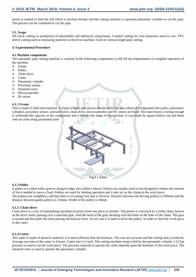
4.1.1 Frame
This is made of mild steel material. A frame is major part in core shooter and it the area where all components like pulley, pneumatic
cylinders, proximity sensor, solenoid valve, chain drive, microcontroller and DC motor are fixed. The main frame is strong enough
to withstand the capacity of the components and it defines the shape of the machine. It was made by square hollow rod and these
rods are joint using permanent joint
Fig.4.1 frame
4.1.2 Pulley
A pulley is a wheel with a groove along its edge, also called a sheave. Pulleys are usually used in sets designed to reduce the amount
of force needed to move a load. Pulleys are used for feeding operation and it also act as the clamp to the work piece.
The pulleys are weightless, and that there is no energy loss due to friction. Distance between the driving pulleys is 280mm and the
distance between guide pulleys is 110mm. Width of the pulley is 30mm.
4.1.3. Chain drive
Chain drive is a way of transmitting mechanical power from one place to another. The power is conveyed by a roller chain, known
as the drive chain, passing over a sprocket gear, with the teeth of the gear meshing with the holes in the links of the chain. The gear
is turned and this pulls the chain putting mechanical force. In our case it is used to drive the pulley. In order to feed the work piece
to the cutter.
4.1.4 Cutter
The cutter is made of abrasive material; it is more efficient than the hacksaw. The cuts are accurate and the cutting time is reduced.
Average run time of the cutter is 4 hours. Cutter size is 5 inch. The cutting machine setup is fed by the pneumatic cylinder 1.22 bar
pressure is used to cut the work piece. The pressure required to operate the cutter depends upon the diameter of the work piece. The
solenoid valve is used to operate the pneumatic cylinder.
© 2019 JETIR March 2019, Volume 6, Issue 3 www.jetir.org (ISSN-2349-5162)
JETIR1903E51 Journal of Emerging Technologies and Innovative Research (JETIR) www.jetir.org 336
4.1.5 Pneumatic cylinder
The pneumatic cylinder is a device which is operated with the help of compressed air. The stroke length of pneumatic cylinder 1 is
100 and bore diameter is 32, the stroke length of pneumatic cylinder 2 is 125 and bore diameter is 25. Solenoid valve is used to
operate the pneumatic cylinder 1. The pressure maintained is 1.22 bars and it is used for cutting operation. The pneumatic cylinder
2 is used for clamping operation.
4.1.6 Solenoid valves
Solenoid valve is a device which is used to operate the pneumatic cylinder. Two 5/2 solenoid valves are used. It is used to control
the flow of air in the pneumatic cylinders. 12volt coil is used in this solenoid valves. This microcontroller gives supply to the
solenoid valve. The coil gets energized and controls the pneumatic cylinder.
4.1.7Proximity sensor A proximity sensor is a sensor able to detect the presence of nearby objects without any physical contact. A proximity sensor
often emits an electromagnetic field or a beam of electromagnetic radiation and looks for changes in the field or return signal.
4.1.8 Microcontroller
5038 Microcontroller is used. It is a small computer on a single integrated circuit. It consists of a microprocessor. It receives signal
from the proximity sensor and actuates the solenoid valve. It is powered with the help of battery.
4.1.9 DC motor
A 12v DC motor is used. It is used to drive the bevel gears attached to the chain drive. The motor provides the necessary for the
displacement of the machine. The motor is mounted at the bottom of the frame and it is coupled to the bevel gears. The rated speed
of the motor is 45rpm at no load condition and has a rated capacity of 100watts.
4.1.10 Clamps
Two clamps made of MS are used. They are mounted on the frame, one is operated with the help of pneumatic cylinders and other
clamp is operated with the help of spring tension. They prevent the slippage of work piece during cutting operation.
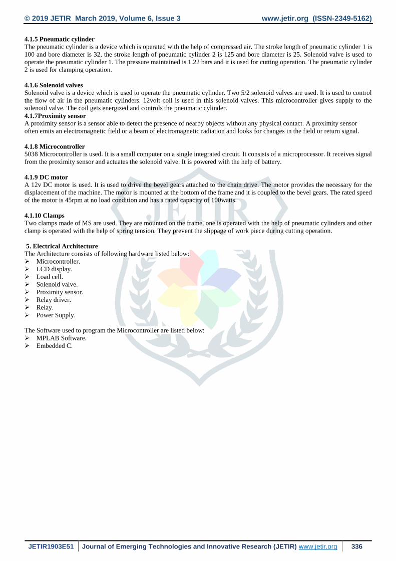
5. Electrical Architecture
The Architecture consists of following hardware listed below:
Microcontroller.
LCD display.
Load cell.
Solenoid valve.
Proximity sensor.
Relay driver.
Relay.
Power Supply.
The Software used to program the Microcontroller are listed below:
MPLAB Software.
Embedded C.
© 2019 JETIR March 2019, Volume 6, Issue 3 www.jetir.org (ISSN-2349-5162)
JETIR1903E51 Journal of Emerging Technologies and Innovative Research (JETIR) www.jetir.org 337
Fig 5.1. Block diagram of electrical architecture of pipe cutting machine
6. Fabrication process
The Fabrication processes has some design calculations to solve the errors while fabricating the equipment to mold up to a set of
assembly and not involving any resistance to each other to form a problem to the project and it is well analyzed in the design
software also.
6.1 Sequence of operation
The pipe cutting operation has to undergo steps in the below given sequential order.
Feed bar stock to stopper that is set according to length of work piece to be cut
Clamp the bar stock
Feed the cutter blade to cut the required length
Retract the cutter
De-clamp the work piece
7. Design Calculations
Design calculation for pneumatic cylinder (32 x100)
Mini pressure applied in the cylinder (p): 2x10⁵N/m2
Diameter of the cylinder (D) : 32 mm
Stroke length : 100 mm
Area of cylinder (A) : (3.14/4*(D2)
: (.785x.0322) : 8.0384 x 10⁻⁴m2
Force exerted in the piston (F) : Pressures applied X area of cylinder
Force : (2 x 10⁵ n /m2)
(8.0384 x 10⁻⁴m2)
: 160.68 N
For lifting one kg weight, the force required is given by,
Force = m x a
= 10 x9.81
= 98.1 N
And the pressure required for one pneumatic cylinder to lift 10 kg is given by,
Pressure, P = Force/ Area
= 98.1 N/8.0384 x 10-4 m2
= 122039.2 N/m2
= 122039.2 pa
© 2019 JETIR March 2019, Volume 6, Issue 3 www.jetir.org (ISSN-2349-5162)
JETIR1903E51 Journal of Emerging Technologies and Innovative Research (JETIR) www.jetir.org 338
Pressure = 1.220392 bar
Maximum load in the cylinder = Pressure*area
= 97.9 N
Specifications of dc motor
Speed = 45 RPM
Voltage = 12 VOLT
Watts = 18 WATT
Power P = I × V
Where
V = 12
W = 18
I = 18/12
= 1.5 A
Torque of the motor
Torque = (P X 60) / (2 X 3.14 X N)
Torque = (18X 60) / (2 X 3.14 X 30)
Torque = 5.72 Nm
Torque = 5.72 x 10³ N mm
The shaft is made of MS and its allowable shear stress = 42 MPa
Battery calculation
To find the Current
Watt = 18 w
Volt = 12v
Current = ?
P = V x I
18 = 12 x I
I = 18/12
= 1.5 AMPS
Battery usage with 1.5 amps
BAH /I
8/1.5 = 5.3 hrs
Battery calculation
To find the Current
Watt = 18 w
Volt = 12v
Current = ?
P = V x I
18 = 12 x I
I = 18/12
= 1.5 AMPS
Battery usage with 1.5 amps
BAH /I
8. Results and discussion
Depending upon the parameters that are variable such as length, diameter, material to be drilled.

© 2019 JETIR March 2019, Volume 6, Issue 3 www.jetir.org (ISSN-2349-5162)
JETIR1903E51 Journal of Emerging Technologies and Innovative Research (JETIR) www.jetir.org 339
Table 8.1 Trial of cutting operation in stainless steel & mild steel
Material Length
(mm)
Diameter
(mm)
Time
(sec)
Mild steel
L1 10 12
L1 15 14
L1 20 16
L2 10 13
L2 15 15
L2 20 17
L3 10 14
L3 15 16
L3 20 18
Stainless steel
L1 10 15
L1 15 17
L1 20 19
L2 10 16
L2 15 18
L2 20 20
L3 10 17
L3 15 19
L3 20 21
The effectiveness of these parameters can vary according to the thickness of workpiece and working conditions in which the cutting
operation is done. The variations are tabulated and assessed as given in Table 4.4.
Where,
L1 – 50mm
L2 – 100mm
L3 – 150mm
8.1 Graphs of Mild steel and stainless-steel length
8.1.1 Length 1
In this graph it explains that, if the length is less then time taken to cut the pipe is less. The blue line indicates the time taken to cut
mild steel pipe and the orange line indicates the time taken to cut stainless steel.

© 2019 JETIR March 2019, Volume 6, Issue 3 www.jetir.org (ISSN-2349-5162)
JETIR1903E51 Journal of Emerging Technologies and Innovative Research (JETIR) www.jetir.org 340
Fig.8.1 Time taken to cut the pipe of length 1
8.1.2 Length 2
In this graph it explains that, if the length is moderate then time taken to cut the pipe is also moderate.
Fig.8.2 Time taken to cut the pipe of length 2
8.1.3 Length 3
In this graph it explains that, if the length is more then time taken to cut the pipe is also less.
0
2
4
6
8
10
12
14
16
18
20
10 15 20
TIM
E T
AK
EN
(se
c)
DIAMETER (mm)
MILD STEEL
STAINLESS STEEL
0
5
10
15
20
25
10 15 20
TIM
E T
AK
EN
(se
c)
DIAMETER (mm)
MILD STEEL
STAINLESS STEEL
© 2019 JETIR March 2019, Volume 6, Issue 3 www.jetir.org (ISSN-2349-5162)
JETIR1903E51 Journal of Emerging Technologies and Innovative Research (JETIR) www.jetir.org 341
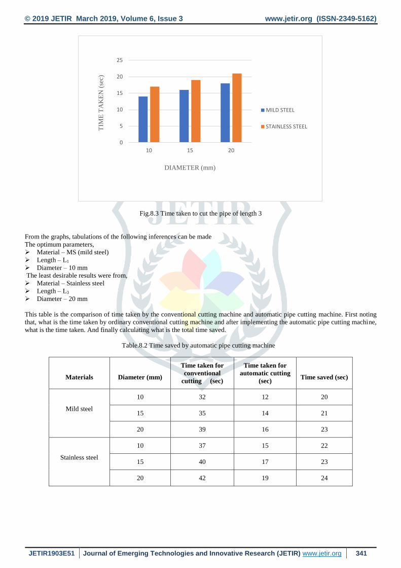
Fig.8.3 Time taken to cut the pipe of length 3
From the graphs, tabulations of the following inferences can be made
The optimum parameters,
Material – MS (mild steel)
Length – L1
Diameter – 10 mm
The least desirable results were from,
Material – Stainless steel
Length – L3
Diameter – 20 mm
This table is the comparison of time taken by the conventional cutting machine and automatic pipe cutting machine. First noting
that, what is the time taken by ordinary conventional cutting machine and after implementing the automatic pipe cutting machine,
what is the time taken. And finally calculating what is the total time saved.
Table.8.2 Time saved by automatic pipe cutting machine
Materials
Diameter (mm)
Time taken for
conventional
cutting (sec)
Time taken for
automatic cutting
(sec)
Time saved (sec)
Mild steel
10 32 12 20
15 35 14 21
20 39 16 23
Stainless steel
10 37 15 22
15 40 17 23
20 42 19 24
0
5
10
15
20
25
10 15 20
TIM
E T
AK
EN
(se
c)
DIAMETER (mm)
MILD STEEL
STAINLESS STEEL

© 2019 JETIR March 2019, Volume 6, Issue 3 www.jetir.org (ISSN-2349-5162)
JETIR1903E51 Journal of Emerging Technologies and Innovative Research (JETIR) www.jetir.org 342
9. Conclusion
Finally, the Automatic pipe cutting machine has been assembled and various observations such as different time taken and
production rate with respect to the speed and using different workpieces were successfully carried out. This project is made with
proper planning. Smoother and noiseless operation by the medium of “Automatic pipe cutting machine”. This project is designed
with the hope that it is very much economical and helpful to many industries and workshops. As per the test conducted in the
different vehicles the developed automated pipe cutting machine reduces 75% of the time consumed by the manual pipe cutting
process. The production rate can be optimized effectively by implementing automatic pipe cutting machine during machining
process. Thus, we have completed the project successfully.
It is justified that our design is more efficient than manual cutting, it reduces the overall cutting time by 75%.
The further development of the tool involves replacement of flat pulleys instead of groove pulleys which makes the handling
of the square pipe possible.
10. References
[1]. Prof. P.D. Menghani, Akarsh Jaiswal, Nikhil Jain, and Mansi Borse, “Automatic Pipe Cutting Machine”, International
Conference on Ideas, Impact and Innovation in Mechanical Engineering (ICIIIME 2017) Volume: 5 Issue: 6.
[2]. Mr. Pandit Mandar Bipinchandra, Mr. Pathan Arfat Sherkhan, “Design & Fabrication of Automatic- Pneumatic Pipe
Cutting Machine”, International Journal of Modern Trends in Engineering and Research, April, 2016.
[3]. Ajit Kumar Singh & Harpreet Singh, “Design and Fabrication of Pneumatic Auto Sheet Metal Cutting Machine Using
Solar Energy”, March-2015.
[4]. P.Balashanmugam and G. Balasubramanian, “Design and Fabrication of Typical Pipe Cutting Machine”, May- 2015.
[5]. Shinde Kailasingh &Anish Jahagirdar, “Study of Automatic Pipe/ Rod Slitting Machine (Pneumatically Controlled)”, 2014.
Related Documents