Design and Evaluation of a PIFA Array for MIMO-Enabled Portable Wireless Communication Devices Rashid A. Bhatti*, Mingoo Choi, JangHwan Choi, and Seong Ook Park Information and Communications University, Yuseong-gu, Daejeon, Korea E-mail: {rashid, layers, jhchoi, sopark}@icu.ac.kr Introduction Performance of MIMO-enabled portable devices is heavily dependent on the characteristics of its antenna arrays [1]-[2]. A typical MIMO antenna array for portable devices should have compact structure, high radiation efficiency, and low spatial correlation in addition to the required bandwidth and nearly omni-directional radiation pattern. Various MIMO antenna arrays for portable devices have been reported in the literature where mostly the frequency of interest is either 2.4 GHz or 5.2 GHz [3]-[8]. In this paper, design and experimental characterization of a four-element PIFA array for MIMO-enabled portable devices is presented. Basic element of the array is a compact PIFA structure with a volume of 0.16 cm 3 . PIFA elements are symmetrically located at the corners of a rectangular PAD-sized ground plane. The antenna array is initially characterized by measuring scattering parameters and radiation patterns at the individual antenna ports. In order to measure channel impulse responses, indoor MIMO measurements under line-of-sight (LOS) and non-line-of-sight (NLOS) propagation conditions are then performed for a linear array of monopoles and the PIFA array. The measured channel data is then post-processed to evaluate spatial correlation and capacity for the two arrays. Power azimuth spectrum (PAS) at LOS and NLOS locations is estimated to determine the angle-of-arrival information for the significant multipaths. Capacity and spatial correlation for the PIFA array under both propagation scenarios are compared to that of the standard quarter-wave monopole array. Design of PIFA Array The proposed MIMO array consists of four elements symmetrically located at the corners of a PDA-sized ground plane. Basic element of the array is a single band PIFA with L- shaped slot in the horizontal part of the radiating element. Slot is created to increase the surface current path length. The PIFA structure is bent at the slot for further compact construction resulting in a total volume of 0.16 cm 3 . The antenna has a 1 mm wide short- circuiting strip and is fed through a semi-ridged coaxial cable. PIFA element and the array are shown in Figure 1(a) and (b) respectively. Spacing between the feed and short points is adjusted for impedance matching over the desired frequency band of 3.7 GHz to 4.2 GHz. Dependence of the antenna operating frequency on slot length is shown in Fig. 2(a). S-parameters of the array are shown in Fig. 2(b). The antennas were fabricated using a copper sheet of 0.2 mm thickness. The PIFA array was then characterized initially by measuring scattering parameters and radiation patterns and finally through indoor MIMO measurements. Radiation patterns of PIFA-1 in the array environment are shown in Fig. 3. A four-element linear array of quarter-wave monopoles was also constructed and used to measure the channel matrix for comparison purposes. Spatial correlation and capacity are calculated through the measured channel matrix data for both the proposed PIFA and the monopole arrays. 978-1-4244-2042-1/08/$25.00 ©2008 IEEE

Welcome message from author
This document is posted to help you gain knowledge. Please leave a comment to let me know what you think about it! Share it to your friends and learn new things together.
Transcript
Design and Evaluation of a PIFA Array for MIMO-Enabled Portable Wireless Communication Devices
Rashid A. Bhatti*, Mingoo Choi, JangHwan Choi, and Seong Ook Park Information and Communications University, Yuseong-gu, Daejeon, Korea
E-mail: {rashid, layers, jhchoi, sopark}@icu.ac.kr
Introduction
Performance of MIMO-enabled portable devices is heavily dependent on the characteristics of its antenna arrays [1]-[2]. A typical MIMO antenna array for portable devices should have compact structure, high radiation efficiency, and low spatial correlation in addition to the required bandwidth and nearly omni-directional radiation pattern. Various MIMO antenna arrays for portable devices have been reported in the literature where mostly the frequency of interest is either 2.4 GHz or 5.2 GHz [3]-[8]. In this paper, design and experimental characterization of a four-element PIFA array for MIMO-enabled portable devices is presented. Basic element of the array is a compact PIFA structure with a volume of 0.16 cm3. PIFA elements are symmetrically located at the corners of a rectangular PAD-sized ground plane. The antenna array is initially characterized by measuring scattering parameters and radiation patterns at the individual antenna ports. In order to measure channel impulse responses, indoor MIMO measurements under line-of-sight (LOS) and non-line-of-sight (NLOS) propagation conditions are then performed for a linear array of monopoles and the PIFA array. The measured channel data is then post-processed to evaluate spatial correlation and capacity for the two arrays. Power azimuth spectrum (PAS) at LOS and NLOS locations is estimated to determine the angle-of-arrival information for the significant multipaths. Capacity and spatial correlation for the PIFA array under both propagation scenarios are compared to that of the standard quarter-wave monopole array.
Design of PIFA Array
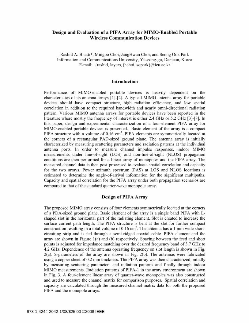
The proposed MIMO array consists of four elements symmetrically located at the corners of a PDA-sized ground plane. Basic element of the array is a single band PIFA with L-shaped slot in the horizontal part of the radiating element. Slot is created to increase the surface current path length. The PIFA structure is bent at the slot for further compact construction resulting in a total volume of 0.16 cm3. The antenna has a 1 mm wide short-circuiting strip and is fed through a semi-ridged coaxial cable. PIFA element and the array are shown in Figure 1(a) and (b) respectively. Spacing between the feed and short points is adjusted for impedance matching over the desired frequency band of 3.7 GHz to 4.2 GHz. Dependence of the antenna operating frequency on slot length is shown in Fig. 2(a). S-parameters of the array are shown in Fig. 2(b). The antennas were fabricated using a copper sheet of 0.2 mm thickness. The PIFA array was then characterized initially by measuring scattering parameters and radiation patterns and finally through indoor MIMO measurements. Radiation patterns of PIFA-1 in the array environment are shown in Fig. 3. A four-element linear array of quarter-wave monopoles was also constructed and used to measure the channel matrix for comparison purposes. Spatial correlation and capacity are calculated through the measured channel matrix data for both the proposed PIFA and the monopole arrays.
978-1-4244-2042-1/08/$25.00 ©2008 IEEE
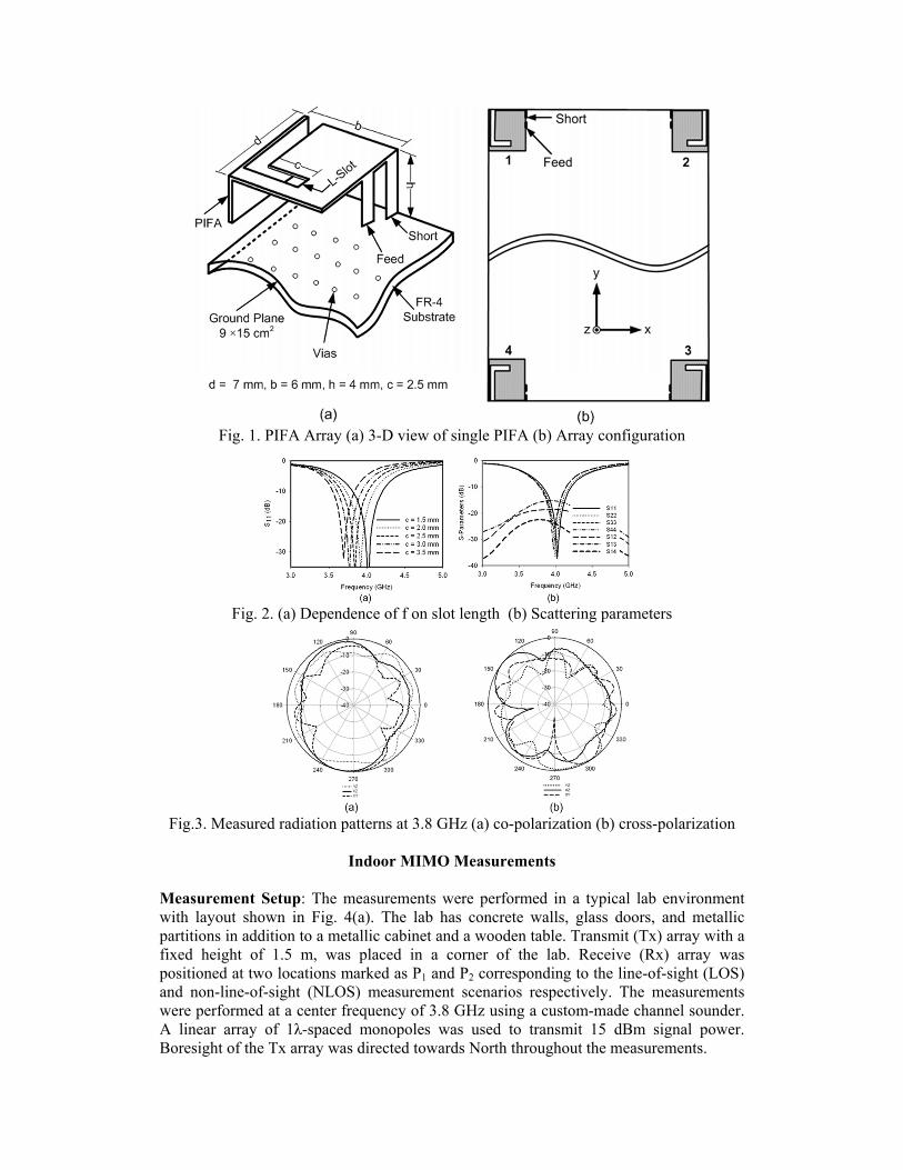
Fig. 1. PIFA Array (a) 3-D view of single PIFA (b) Array configuration
Fig. 2. (a) Dependence of f on slot length (b) Scattering parameters
Fig.3. Measured radiation patterns at 3.8 GHz (a) co-polarization (b) cross-polarization
Indoor MIMO Measurements
Measurement Setup: The measurements were performed in a typical lab environment with layout shown in Fig. 4(a). The lab has concrete walls, glass doors, and metallic partitions in addition to a metallic cabinet and a wooden table. Transmit (Tx) array with a fixed height of 1.5 m, was placed in a corner of the lab. Receive (Rx) array was positioned at two locations marked as P1 and P2 corresponding to the line-of-sight (LOS) and non-line-of-sight (NLOS) measurement scenarios respectively. The measurements were performed at a center frequency of 3.8 GHz using a custom-made channel sounder. A linear array of 1λ-spaced monopoles was used to transmit 15 dBm signal power. Boresight of the Tx array was directed towards North throughout the measurements.
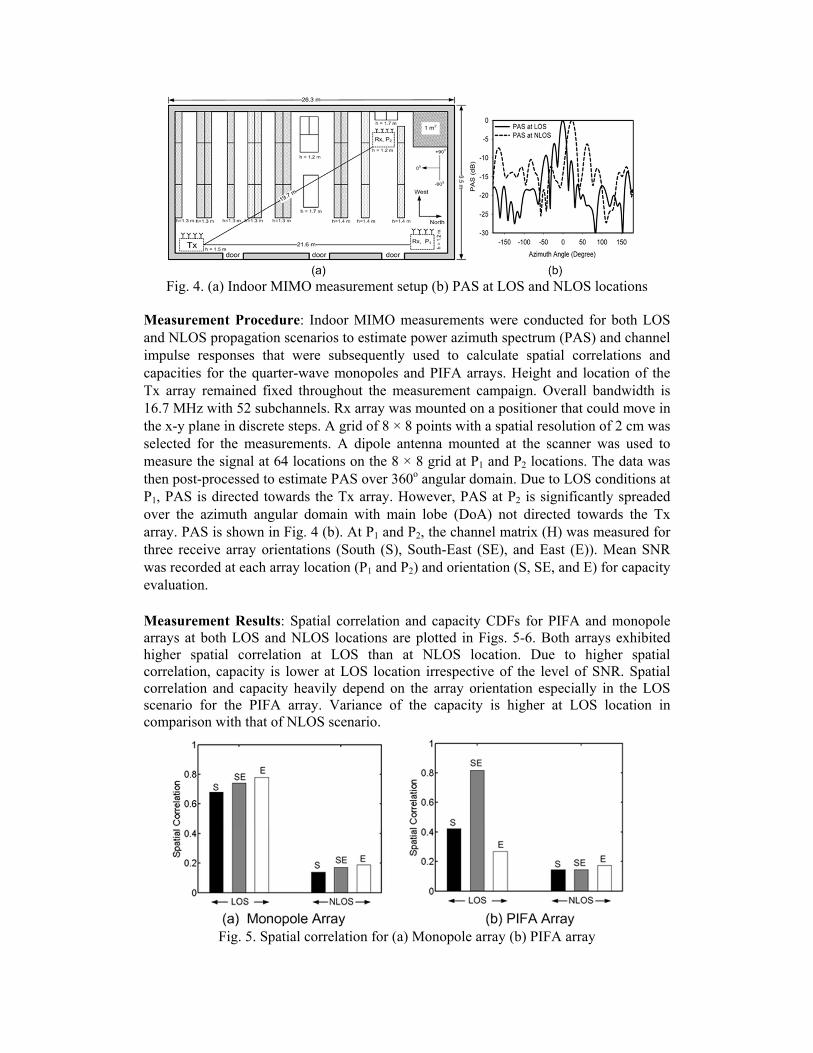
Fig. 4. (a) Indoor MIMO measurement setup (b) PAS at LOS and NLOS locations
Measurement Procedure: Indoor MIMO measurements were conducted for both LOS and NLOS propagation scenarios to estimate power azimuth spectrum (PAS) and channel impulse responses that were subsequently used to calculate spatial correlations and capacities for the quarter-wave monopoles and PIFA arrays. Height and location of the Tx array remained fixed throughout the measurement campaign. Overall bandwidth is 16.7 MHz with 52 subchannels. Rx array was mounted on a positioner that could move in the x-y plane in discrete steps. A grid of 8 × 8 points with a spatial resolution of 2 cm was selected for the measurements. A dipole antenna mounted at the scanner was used to measure the signal at 64 locations on the 8 × 8 grid at P1 and P2 locations. The data was then post-processed to estimate PAS over 360o angular domain. Due to LOS conditions at P1, PAS is directed towards the Tx array. However, PAS at P2 is significantly spreaded over the azimuth angular domain with main lobe (DoA) not directed towards the Tx array. PAS is shown in Fig. 4 (b). At P1 and P2, the channel matrix (H) was measured for three receive array orientations (South (S), South-East (SE), and East (E)). Mean SNR was recorded at each array location (P1 and P2) and orientation (S, SE, and E) for capacity evaluation. Measurement Results: Spatial correlation and capacity CDFs for PIFA and monopole arrays at both LOS and NLOS locations are plotted in Figs. 5-6. Both arrays exhibited higher spatial correlation at LOS than at NLOS location. Due to higher spatial correlation, capacity is lower at LOS location irrespective of the level of SNR. Spatial correlation and capacity heavily depend on the array orientation especially in the LOS scenario for the PIFA array. Variance of the capacity is higher at LOS location in comparison with that of NLOS scenario.
Fig. 5. Spatial correlation for (a) Monopole array (b) PIFA array
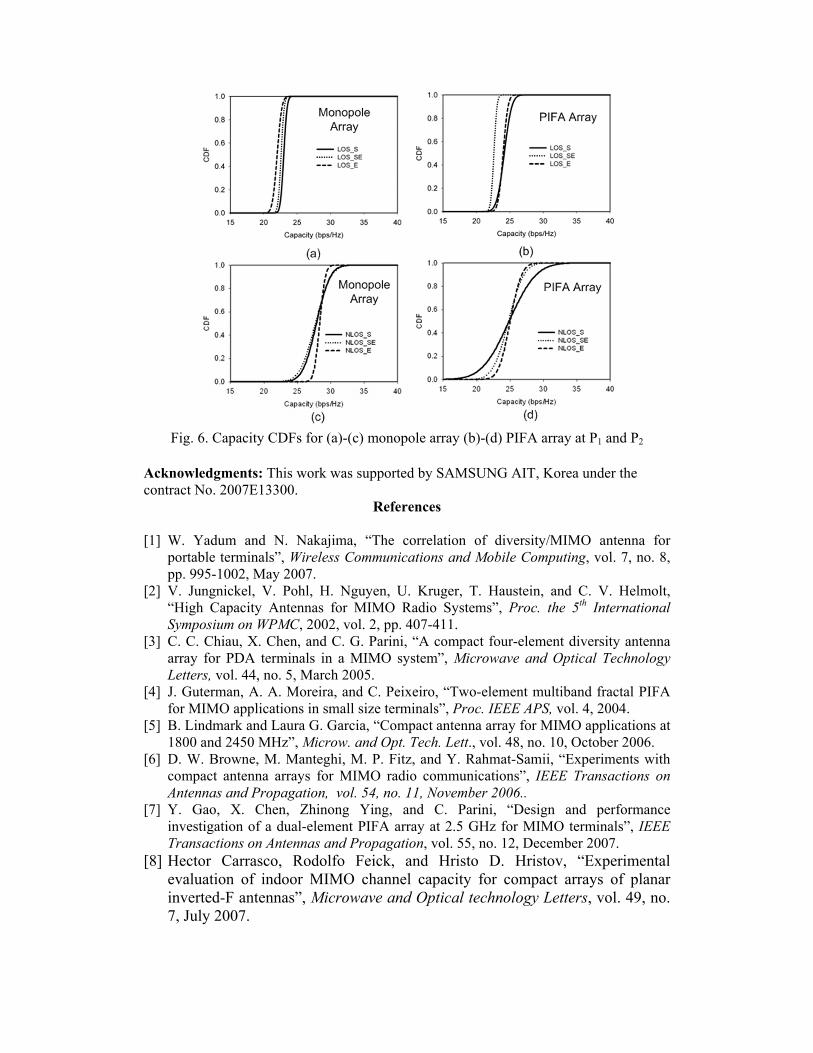
Fig. 6. Capacity CDFs for (a)-(c) monopole array (b)-(d) PIFA array at P1 and P2
Acknowledgments: This work was supported by SAMSUNG AIT, Korea under the contract No. 2007E13300.
References
[1] W. Yadum and N. Nakajima, “The correlation of diversity/MIMO antenna for portable terminals”, Wireless Communications and Mobile Computing, vol. 7, no. 8, pp. 995-1002, May 2007.
[2] V. Jungnickel, V. Pohl, H. Nguyen, U. Kruger, T. Haustein, and C. V. Helmolt, “High Capacity Antennas for MIMO Radio Systems”, Proc. the 5th International Symposium on WPMC, 2002, vol. 2, pp. 407-411.
[3] C. C. Chiau, X. Chen, and C. G. Parini, “A compact four-element diversity antenna array for PDA terminals in a MIMO system”, Microwave and Optical Technology Letters, vol. 44, no. 5, March 2005.
[4] J. Guterman, A. A. Moreira, and C. Peixeiro, “Two-element multiband fractal PIFA for MIMO applications in small size terminals”, Proc. IEEE APS, vol. 4, 2004.
[5] B. Lindmark and Laura G. Garcia, “Compact antenna array for MIMO applications at 1800 and 2450 MHz”, Microw. and Opt. Tech. Lett., vol. 48, no. 10, October 2006.
[6] D. W. Browne, M. Manteghi, M. P. Fitz, and Y. Rahmat-Samii, “Experiments with compact antenna arrays for MIMO radio communications”, IEEE Transactions on Antennas and Propagation, vol. 54, no. 11, November 2006..
[7] Y. Gao, X. Chen, Zhinong Ying, and C. Parini, “Design and performance investigation of a dual-element PIFA array at 2.5 GHz for MIMO terminals”, IEEE Transactions on Antennas and Propagation, vol. 55, no. 12, December 2007.
[8] Hector Carrasco, Rodolfo Feick, and Hristo D. Hristov, “Experimental evaluation of indoor MIMO channel capacity for compact arrays of planar inverted-F antennas”, Microwave and Optical technology Letters, vol. 49, no. 7, July 2007.
Related Documents