N E W S L E T T E R DESIGN AND DEVELOPMENT OF SHUT-OFF ROD DRIVE MECHANISM FOR THE ‘CRITICAL FACILITY’ N.K. Singh, M.K. Mishra, N.S. Dalal, G. Veda Vyas, C.B. Kothari, D.N. Badodkar and Manjit Singh Division of Remote Handling & Robotics (DRHR), BARC Preamble The ‘Critical Facility’ is a low power research reactor, being commissioned at BARC, Trombay. It will be used for conducting lattice physics experiments, for validating physics design parameters, for future generation Advance Heavy Water Reactors (AHWRs) and also for 540 MW e PHWRs. This reactor has built-in design features, which allow the arrangement of fuel rods, safety rods and experimental assemblies, in the variable lattice spacing, to simulate different core configurations, for conducting various reactor physics experiments. This work is being taken up under the X plan project ‘Advance Reactor Development Programme’ The Control Mechanism Section, DRHR has been working on the design and development of reactivity control mechanisms for research reactors and for 220 MW e /540 MW e PHWRs. This paper presents the functional requirements, design specifications, a brief description and salient design features of shut-off rod drive mechanism for the ‘Critical Facility’. Current status of this development work is highlighted in the concluding remarks. No. 247 August 2004 C o n t e n t s 1. Design and development of shut-off rod drive mechanism for the ‘Critical Facility’……………………… .1 2. Drum manipulator …………10 3. IAEA – Regional workshop on development of national strategies for improving control over radioactive sources including orphan sources …11 4. Advanced workshop on radiochemistry and applications of radioisotopes ………………13 5. Training course in basic radiation protection ………..15 6. International conference on recent trends in radiation biology ……………………. 15 7. Fourth DAE-BRNS National Laser Symposium (NLS-4) ………16 8. BARC transfers know-how of "Nisargruna - a biogas plant"…………………………17 9. BARC transfers technology of ‘Alarm Annunciation System’ to ECIL …………..18 10. ž¸¸.œ¸.‚. ˆ½¿ÅÍ ˆ½Å ¨¸¾±¸¸¹›¸ˆÅ¸½¿ ˆÅ¸½ ¬¸ŸŸ¸¸›¸ / BARC scientists honoured ……….19

Welcome message from author
This document is posted to help you gain knowledge. Please leave a comment to let me know what you think about it! Share it to your friends and learn new things together.
Transcript

N E W S L E T T E R
DESIGN AND DEVELOPMENT OF SHUT-OFF ROD DRIVE MECHANISM FOR THE ‘CRITICAL FACILITY’ N.K. Singh, M.K. Mishra, N.S. Dalal, G. Veda Vyas, C.B. Kothari, D.N. Badodkar and Manjit Singh Division of Remote Handling & Robotics (DRHR), BARC
Preamble The ‘Critical Facility’ is a low power research reactor, being commissioned at BARC, Trombay. It will be used for conducting lattice physics experiments, for validating physics design parameters, for future generation Advance Heavy Water Reactors (AHWRs) and also for 540 MWe PHWRs. This reactor has built-in design features, which allow the arrangement of fuel rods, safety rods and experimental assemblies, in the variable lattice spacing, to simulate different core configurations, for conducting various reactor physics experiments. This work is being taken up under the X plan project ‘Advance Reactor Development Programme’ The Control Mechanism Section, DRHR has been working on the design and development of reactivity control mechanisms for research reactors and for 220 MWe/540 MWe PHWRs. This paper presents the functional requirements, design specifications, a brief description and salient design features of shut-off rod drive mechanism for the ‘Critical Facility’. Current status of this development work is highlighted in the concluding remarks.
No. 247 August 2004
C o n t e n t s
1. Design and development of shut-off rod drive mechanism for the ‘Critical
Facility’……………………… .1
2. Drum manipulator …………10
3. IAEA – Regional workshop on development of national strategies for improving control over radioactive sources including orphan sources …11
4. Advanced workshop on radiochemistry and applications of radioisotopes ………………13
5. Training course in basic radiation protection ………..15
6. International conference on recent trends in radiation biology ……………………. 15
7. Fourth DAE-BRNS National Laser Symposium (NLS-4) ………16
8. BARC transfers know-how of "Nisargruna - a biogas plant"…………………………17
9. BARC transfers technology of ‘Alarm Annunciation System’ to ECIL …………..18
10. ž¸¸.œ¸.‚. ˆ½¿ÅÍ ˆ½Å ¨¸¾±¸¸¹›¸ˆÅ¸½¿ ˆÅ¸½ ¬¸ŸŸ¸¸›¸ / BARC scientists honoured ……….19

Introduction The mechanical shut-off rods constitute one of the most critical safety systems of a reactor. The ‘Critical Facility’ utilises six fast-acting mechanical shut-off rods. The principal purpose of the mechanical shut-off rods is to provide a reliably negative reactivity, within a specified time and render the reactor adequately sub-critical, following operational transients, postulated initiating events as well as under normal operating conditions as required. However, in case of a reactor trip, the moderator is also dumped to a predetermined level, which provides an additional shut down margin.
The drive mechanism is designed to meet required functional requirements which include rod raising/lowering/holding, fail-safe and non-reverse scram characteristics, size constraints, rod position indication, end limit indications (direct/indirect), environmental conditions, service life and minimum maintenance conditions.
Fig.1 gives the location plan for shut-off rods. Under normal operating conditions, all the shut-
off rods are parked above the core. They are independently driven. For reactor shut down, all the rods fall freely under gravity into the reactor core, in a specified time. At the time of reactor start up, the rods are withdrawn, one rod at a time, in a given sequence, at a speed such that reactivity addition rate is limited to the desired value, from reactor physics considerations. Single rod failure criterion is taken into consideration for the purpose of safety analysis.
Description
The Shut-off rod drive mechanism consists of the absorber assembly and the headgear assembly.
Absorber assembly
The Absorber assembly consists of Guide tube locator, Guide tube, Transition piece, Push tube sub-assembly, Absorber element sub-assembly and Disc spring sub-assembly.
The Guide tube (Aluminium Grade 57S) is closed at the bottom and hence the absorber element and mechanism components are not in contact with the moderator. The Guide tube

locator (SS 304) rests on the girder and the drive mechanism is mounted to the girder through this locator. The guide tube rests inside the guide tube locator and fits precisely into it. The Push tube sub-assembly rests inside the guide tube locator and on the guide tube top face. This sub-
assembly has a disc at the bottom and a plunger at the top. When the absorber element is taken up, the element top attachment pushes this disc against a helical spring, also known as the initial accelerating spring, thereby, pushing the
plunger, which in turn, actuates the direct top micro switches. These are housed inside the drive mechanism. When absorber element reaches it's top limit, the initial accelerating spring is in compressed condition. During scram, the element is made to fall freely inside the guide
tube and the initial accelerating spring assists this free fall (it provides the initial thrust to the element, overcoming inertia, for it's downward fall). The maximum compression of this spring is
Fig. 2: Absorber assembly details
Absorber assembly alongwith Headgear

about 100 mm giving a maximum thrust of 8 Kgs to the element. There is a provision to adjust the spring compression and hence the initial thrust to be imparted to the absorber element can be controlled. The push tube sub-assembly also carries another helical spring, known as cushioning spring, which damps out the plunger downward movement, at the time of rod release. The Absorber sub-assembly consists of the absorber element (Cadmium sandwiched between two Aluminium tubes Grade 1S) and it's top attachment. The top attachment is joined to the element through a threaded joint after fitting, this joint is locked using two rivets. The wire rope end, through a support pad, is attached to the top attachment. The wire rope passes through the push tube assembly and it's other end is attached to the sheave in the drive mechanism assembly. Absorber assembly details are shown in Fig. 2.
Headgear assembly An electromechanical cable-winch-type drive is selected for this purpose. The shut-off rod headgear assembly is mounted on the girders. General assembly and details are shown in Fig. 3. The headgear consists of the following sub-assemblies: 1. Motor sub-assembly 2. Worm gear sub-assembly 3. Electromagnetic (EM) clutch sub-assembly 4. Reduction Unit-I sub-assembly 5. Mechanism housing sub-assembly 6. Sheave shaft sub-assembly 7. Position Indication (PI) unit sub-assembly 8. Reduction a Unit-II sub-assembly 9. Hydraulic dashpot sub-assembly 10. Limit switch sub-assembly 11. Direct top indication unit sub-assembly
Fig. 3: General assembly of headgear

The power to drive the absorber rod is provided by a 3-phase, 110 volts, 50 Hz induction motor connected to a Class-II bus (derived from 415/110 volts, 50 Hz transformer). The drive motor, through a pair of worm and worm gear, an electromagnetic clutch and gear reduction stages, is connected to the sheave. One end of the steel wire rope is attached to the sheave, while the other end is connected to the absorber element. In this reactor, all the six shut-off rods are used and every one of them has independent drive. Normally, the rods are parked above the core. For reactor shut down, all the rods fall freely into the core.
As stated earlier the time of reactor start-up, the absorber rods are withdrawn at a predetermined speed, such that, the rate of reactivity addition (even when the rod is reaching it's parking position) is restricted to the desired value, from reactor physics considerations. For the purpose of rod withdrawal, all the rods are grouped into two banks, one of the banks is marked as SR-1, 4 and 5 and other one is marked as SR-2, 3 and 6 (Fig.1). Rod withdrawal speed typically varies from 15 mm/sec (rod is at the bottom) to 21 mm/sec (rod is at the top) and the total rod withdrawal time is 132 sec. ± 5 sec. for a total rod travel of 2400 mm. An electromagnetic clutch acts as coupling between the worm gear unit and a set of spur gears connected to a sheave. The EM clutch is fed from 48 Volts DC power supply (derived from Class-II under normal operating condition and backed up by Class-I). When energized, clutch couples drive motor to the sheave and enables rod to be withdrawn at a predetermined speed. While not in motion, shut-off rod is held in position through irreversible feature of the worm gear unit (built in by design) coupled through gears and energized clutch. However, for reactor shut down function, the clutch is de-energized, making rod to fall freely into the core, as described above. This ensures the ‘fail-safe’ operation of the mechanism.
At the time of rod drop, a set of pick-up rings are made to lapse one after the other. After the rod has travelled 90% of it's specified distance, sheave shaft engages the hydraulic dashpot, which decelerates the rod and helps in bringing down the rod velocity smoothly to zero at the end of travel. When the dashpot is engaged, it rotates the dashpot shaft with two vanes in a hydraulic medium through approximately 120°. As the vanes rotate, fluid on one side of the vane escapes to the other side through narrow passages. This offers high resistance to the rotation of the vane and hence to the falling rod after 90% travel. A mechanical stopper is provided in the dashpot to avoid damage due to the moving vanes hitting the fixed vanes. The vane is designed in such a way that it offers negligible resistance when rotated in the opposite direction i.e. during rod withdrawal. A spiral spring is attached to the dashpot shaft, to bring the dashpot vane back to its normal position, as soon as the rod withdrawal starts. This resets the hydraulic dashpot (100% reset after rod withdrawal by 10% travel from bottom) and readies it to provide damping to the falling rod, if required, during rod withdrawal. In the dashpot assembly, provision is made to mount the pressure transducer for oil pressure measurements. An oil level indicator-cum-oil reservoir is also mounted on the dashpot and this port is used to check the oil level.
The continuous position of the rod is monitored by using a dual type high-precision wire-wound potentiometer, which is connected to the sheave shaft through spur gears. Direct top limit of the rod is given by two sets of two micro-switches, mounted in the bottom part of the headgear (direct top indication unit sub-assembly). These are actuated by a plunger assembly, in which a plunger moves and hits the microswitch lever, when the rod reaches it's top limit. This is also used to cut-off the power supply to the drive motor, during rod withdrawal. Arrangement is also provided to give indirect top end limit indication through two sets of mcroswitches

(PI unit sub-assembly). The Limit switch sub-assembly houses two triplicated cam operated limit switches, which give indirect 90% and 100% rod travel and they are used for drop time measurements. A potentiometer is coupled with the dashpot shaft, and is used to monitor the dashpot shaft movement from 0° through 120°. During rod withdrawal, actuation of 90% indirect is compared with rod position signal (through potentiometer), to generate an interlock, which prevents rod withdrawal beyond 10% travel (from the bottom).
Drive Mechanism Requirements
The shut-off rod drive mechanism is designed to meet the following requirements: • To release the rod within 300 msec
(actuation delay time), upon actuation of the trip signal.
• To provide minimum resistance to rod fall under gravity so as to provide 90% insertion of the rod within a specified time of 1 sec. ± 0.2 sec. (excluding delay time).
• To facilitate the shut-off rod drop at any stage, without external power supply.
• To provide a ‘fail-safe’ operation (shut down function).
• To decelerate the rod during the remaining 10% travel and to bring down the rod terminal velocity smoothly to zero at the end of travel.
• To provide continuous rod-position indications at all locations.
• To provide a reliable facility for withdrawal of the rod, at a given speed.
• To limit rod withdrawal time (motorised) within 132 sec. ± 5 sec.
• To reset the dashpot during initial stage of rod withdrawal so as to provide damping, if the rod is dropped at any stage during withdrawal (after 10% withdrawal).
• To facilitate the monitoring of dashpot vane movement.
• To accommodate the given headgear within a space limitation of 210 mm x 196 mm x 750 mm.
Salient Design Features • Rope-sheave arrangement to eliminate the
rope jumping problem • ‘Fail-safe’ design • 90% free fall, assisted by initial accelerating
spring • Modular design layout for ease of
maintenance. The drive mechanism assembly (along with absorber assembly) can be located at any lattice location.
Basic Design Specifications No. of Shut-off rods : 6 Nos. (independently driven) Absorber rod material : Cadmium sandwiched in Aluminium tubes Absorber element sectional details
Outer Aluminium tube (Grade: 57S) : 64 mm OD x 2 mm WT Cadmium sheet thickness : 1.5 mm ± 0.1 mm Inner Aluminium tube (Grade: 57S) : 57 mm OD x 2 mm WT Total length of absorber element : 1660 mm (including top attachment) Weight of absorber element : ~ 10 Kgs.
Total reactivity worth of SR’s for reference core : 83 mk Total reactivity worth of SR’s for reference core : 66 mk In the absence of the most effective rod. Total reactivity worth of the most effective bank : 33 mk No. of banks : Two

Note:
1. Rod actuation delay is measured from the instant the ‘scram’ switch is actuated to the instant the rod leaves it's parking position (i.e. time from the instant the scram switch contact changeover takes place to the instant the direct top limit switch de-actuates).
2. For safety analysis, total delay time (start of initiating event to the instant the rod leaves it's parking position) is taken as 500 msec.
Table Continued……
Rod withdrawal : One rod at a time Reactor trip : All the rods fall freely under gravity Active length of the absorber (Cadmium) : 1500 mm Total travel Distance : 2400 mm Free fall travel for the rod : 2160 mm (90% of full travel) Rod actuation delay (Refer note 1) : Less than 300 msec. Rod drop time for 90% travel (excluding delay time) : 1 sec. ± 0.2 sec. Rod drop time for 100% travel : 4 sec. ± 2 sec. Tolerance for 90% and 100% travel : 1% of full travel (max.) Rod linear speed during withdrawal
Minimum (rod at the bottom) : ~ 15 mm/sec Maximum (rod at the top) : ~ 21 mm/sec
Total time for rod withdrawal : ~ 132 sec. ± 5 sec. Ambient conditions at the headgear location
Temp. : Normal ambient (55°C max. only during specific experiments) Pressure : ~ 100 mm of water gauge Fluid : Nitrogen saturated with D2O vapour
Max. radiation field at the headgear location : ~ 10 R/hr. Overall size of the headgear : 210 mm x 196 mm x 750 mm height Drive motor : 3 ph induction motor
[fed from 110 Volts (Line), 50 Hz supply] Sheave shaft speed (motorized movement) : ~ 3 rpm EM clutch : 48 Volts DC, 3 Kg.m torque (static)
Wire rope Details : SS 316, 3 mm dia., 540 Kgs breaking load Max. load on the wire rope (Element weight, : ~102 Kgs. (max at 90% rod position) bending load & deceleration load)
Factor of safety for the wire rope : ~5 Maximum load seen by the guide tube (in case of wire rope snap, without taking into account the cushioning effect of bottom disc springs) :
Max. load seen by the guide tube : 18,100 Kgs. Max. stress in the guide tube : 3.83 Kg/mm2 UTS for guide tube material : 19.3 Kg/mm2 (Aluminium grade 57S)
Weight of the headgear assembly (without absorber) : ~ 80 Kgs. Weight of the absorber assembly : ~ 10 Kgs.

Prototyping, Design Qualification and Life Cycle Testing The design of the shut-off rod drive mechanism is tested by prototyping and subjecting it to the cycle testing, under simulated conditions, on a full-scale test station, in accordance with general safety guidelines. A prototype mechanism has
been manufactured and assembled at DRHR, BARC and is being tested on a full-scale test station, using a dummy absorber element of the same size and weight. Fig. 4 shows the photograph of the prototype SOR headgear on full-scale test set-up with test console and Fig. 5 shows the photograph of the full-
Fig.4: Prototype SOR Headgear on full-scale test set-up with Test Console at DRHR
Fig. 5 : Full scale test facility at DRHR

scale test facility at DRHR. A typical rod drop profile (rod velocity/rod position vs time) is shown in Fig 6. Typical values of rod drops data (rod position and time) are given in Table-1. A list of position indicating devices provided in the headgear assembly is given in Table-2. The prototype mechanism has been tested for 5000 drops without maintenance or replacement. Further drop tests are being conducted to establish the design, consistency of rod drop performance and reliability. In general, the ambient temperature at the DM (Drive Mechanism) location is expected to be normal. However, in some physics experiments, the ambient temp. at DM location is expected to go upto a maximum of 55°C. Rod drop
performance has been checked with an ambient temp of 60°C at DM location. Rod drop performance is also established under guide tube filled conditions (postulated event).
0
0.5
1
1.5
2
2.5
3
3.5
0 0.3 0.6 0.9 1.2 1.5 1.8 2.1 2.4 2.7
Time (sec)
Rod
Vel
ocity
(m/s
ec)
0
10
20
30
40
50
60
70
80
90
100
110
Rod
Tra
vel (
%)
Fig. 6: Typical rod drop profile of SOR for the Critical Facility
Table 1: Rod drop data (position and time): typical values
Sr. No. Time (sec) (excluding actuation delay) Rod travel (mm) Rod travel (%)
1. 0 0 0 2. 0.05 20.7 0.87 3. 0.10 68.9 2.90 4. 0.15 103.1 4.33 5. 0.20 157.7 6.62 6. 0.25 222.1 9.32 7. 0.30 272.7 11.44 8. 0.40 472.2 19.81 9. 0.50 667.4 28.00
10. 0.60 858.3 36.02 11. 0.70 1166.9 48.97 12. 0.80 1492.6 62.63 13. 0.90 1803.9 75.69 14. 1.00 2074.3 87.04 15. 1.04 2179.1 91.44 16. 1.10 2256.5 94.69 17. 1.20 2282.0 95.76 18. 1.40 2320.2 97.36 19. 1.60 2327.7 97.68 20. 1.80 2337.8 98.10 21. 2.00 2347.9 98.53 22. 2.40 2368.0 99.37 23. 2.70 2383.1 100
Concluding Remarks The Performance of the prototype headgear on full-scale test station for 5000 drop tests without maintenance or replacement and consistent 90% rod drop performance is considered to be satisfactory. Further cycle testing is in progress. Design Basis Report (DBR) has been submitted for the safety review. Based on satisfactory performance of the prototype drive mechanism on full-scale test set-up, action has been initiated for the manufacture of drive mechanisms for use in the reactor. Seismic qualification of the drive mechanism for OBE and SSE conditions are being taken up with the help from RED. The reactor site facility is categorised as a Class ‘C’ category II structure and design inputs for seismic analysis are based on the guidelines mentioned in the IAEA report TECDOC-348.
References
• Safety assessment report on critical facility for AHWR and 500 MWe PHWR: Chapter 4 on reactor physics and Chapter-7 on Control and Instrumentation.
• Manjit Singh & G. Govindarajan, ‘Evolution of shutdown mechanism for PHWRs’, Workshop on reactor shutdown system held during March 4-6, 1997, IGCAR, III 1.1-III1.14.
• Manjit Singh et al.,‘Design and development of drive mechanisms for adjuster Rods, control rods and shut-off rods of TAPP-3 & 4’- BARC Newsletter, No. 209, June 2001, 10-17.
• Earthquake resistant design of nuclear facilities with limited radioactivity inventory: IAEA TECDOC-348 (Revised Draft of March 1999).
• AERB safety guide on ‘safety critical systems’: AERB/SG/D-10.
• AERB safety guide on ‘core reactivity control’: AERB/SG/D-7.
• AERB safety guide on ‘design basis events’: AERB/SG/D-5.
DRUM MANIPULATOR CDM has designed and manufactured a drum manipulator for Gamma ray scanning of radioactive materials contained in a 200 Ltr drum, (with a maximum weight of 200 Kgs). It consists of two sub-assemblies:
1) Rotary table sub-assembly 2) Vertical column sub-assembly
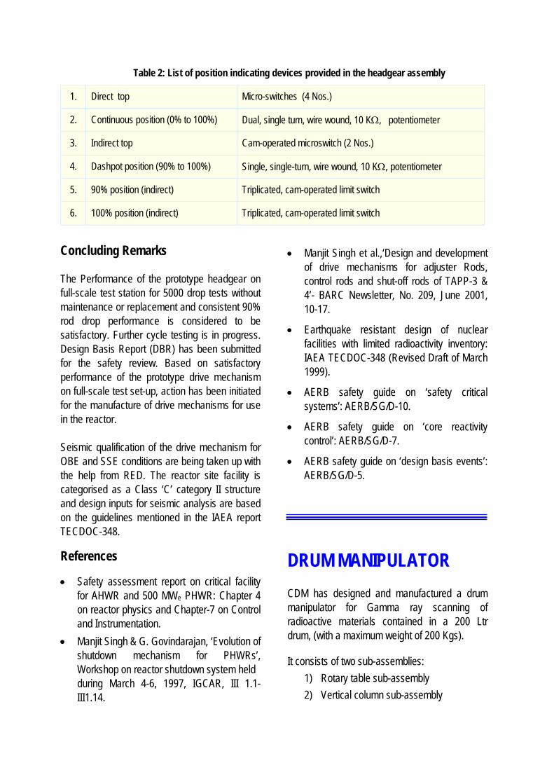
Table 2: List of position indicating devices provided in the headgear assembly
1. Direct top Micro-switches (4 Nos.)
2. Continuous position (0% to 100%) Dual, single turn, wire wound, 10 KΩ, potentiometer
3. Indirect top Cam-operated microswitch (2 Nos.)
4. Dashpot position (90% to 100%) Single, single-turn, wire wound, 10 KΩ, potentiometer
5. 90% position (indirect) Triplicated, cam-operated limit switch
6. 100% position (indirect) Triplicated, cam-operated limit switch
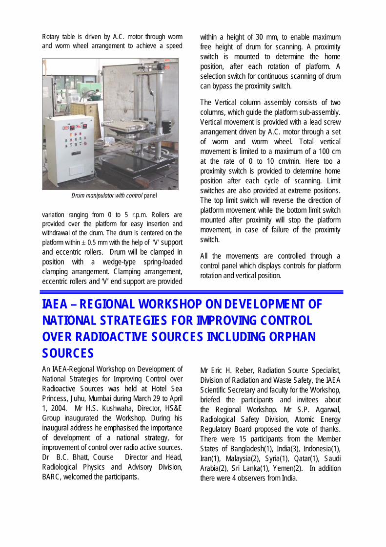
Rotary table is driven by A.C. motor through worm and worm wheel arrangement to achieve a speed
variation ranging from 0 to 5 r.p.m. Rollers are provided over the platform for easy insertion and withdrawal of the drum. The drum is centered on the platform within ± 0.5 mm with the help of 'V' support and eccentric rollers. Drum will be clamped in position with a wedge-type spring-loaded clamping arrangement. Clamping arrangement, eccentric rollers and ‘V’ end support are provided
within a height of 30 mm, to enable maximum free height of drum for scanning. A proximity switch is mounted to determine the home position, after each rotation of platform. A selection switch for continuous scanning of drum can bypass the proximity switch.
The Vertical column assembly consists of two columns, which guide the platform sub-assembly. Vertical movement is provided with a lead screw arrangement driven by A.C. motor through a set of worm and worm wheel. Total vertical movement is limited to a maximum of a 100 cm at the rate of 0 to 10 cm/min. Here too a proximity switch is provided to determine home position after each cycle of scanning. Limit switches are also provided at extreme positions. The top limit switch will reverse the direction of platform movement while the bottom limit switch mounted after proximity will stop the platform movement, in case of failure of the proximity switch.
All the movements are controlled through a control panel which displays controls for platform rotation and vertical position.
IAEA – REGIONAL WORKSHOP ON DEVELOPMENT OF NATIONAL STRATEGIES FOR IMPROVING CONTROL OVER RADIOACTIVE SOURCES INCLUDING ORPHAN SOURCES An IAEA-Regional Workshop on Development of National Strategies for Improving Control over Radioactive Sources was held at Hotel Sea Princess, Juhu, Mumbai during March 29 to April 1, 2004. Mr H.S. Kushwaha, Director, HS&E Group inaugurated the Workshop. During his inaugural address he emphasised the importance of development of a national strategy, for improvement of control over radio active sources. Dr B.C. Bhatt, Course Director and Head, Radiological Physics and Advisory Division, BARC, welcomed the participants.
Mr Eric H. Reber, Radiation Source Specialist, Division of Radiation and Waste Safety, the IAEA Scientific Secretary and faculty for the Workshop, briefed the participants and invitees about the Regional Workshop. Mr S.P. Agarwal, Radiological Safety Division, Atomic Energy Regulatory Board proposed the vote of thanks. There were 15 participants from the Member States of Bangladesh(1), India(3), Indonesia(1), Iran(1), Malaysia(2), Syria(1), Qatar(1), Saudi Arabia(2), Sri Lanka(1), Yemen(2). In addition there were 4 observers from India.
Drum manipulator with control panel

The objective of the workshop was, to evolve national strategies, for control over radioactive sources and to provide practical guidance to the Member States, on the development of national strategy for improving control over radioactive sources, particularly dangerous sources (Categories 1-3). This involves the determination of the magnitude of the potential problem with orphan and vulnerable sources and the evolution and implementation of an appropriate action plan which would result in all significant sources being managed in a safe and secure manner.
The 4-day programme for Regional Workshop consisted of 7 lectures - six delivered by Mr Reber, IAEA and one was delivered by Mr K.V.S. Sastry, BRIT, DAE on recycling of radioactive sources The programme included exercises on preparation of action plan by the participants for improving control over radioactive sources, tailored to suit national needs, presentation of a action plan by the participants, review of action plans presented by the participants, and submission of written action plans. The participants were provided with
copies of IAEA publications, which included the report IAEA - TECDOC - 1388 on “Strengthening control over radioactive sources in authorized use and regaining control over orphan sources”, which was relevant to the topic of the Workshop.
The Workshop concluded on April 1, 2004 at about 12.30 hrs. Valedictory Address was delivered by Mr S.K. Sharma, Vice Chairman, Atomic Energy Regulatory Board. During his address he stressed the need for safety and security of radioactive sources. While presenting his remarks about the Workshop, Mr
Reber, IAEA thanked BARC for hosting the Workshop in India and making excellent arrangements during the Workshop. Mr U.B. Tripathi, Radiological Physics and Advisory Division, BARC, proposed the vote of thanks.
During the feedback session, the participants appreciated the contents of the workshop and thanked IAEA for giving them an opportunity to participate in the Workshop on such an important topic.
Mr H.S. Kushwaha, Director, HS&E Group, BARC, giving the Inaugural Address at the IAEA - Regional Workshop. Seated on the dais (right to left) Mr. Eric H. Reber, Radiation Source Specialist, Division of Radiation and Waste Safety, IAEA, Dr B.C. Bhatt, Course Director and Mr S.P. Agarwal, RSD, AERB.
Mr S.K. Sharma, Vice-Chairman, AERB, giving the Valedictory Address on the concluding day. Seated on the dais (right to left) Mr U.B. Tripathi, RPAD, BARC, Mr Eric H. Reber, IAEA and Dr .B.C. Bhatt, Course Director .

ADVANCED WORKSHOP ON RADIOCHEMISTRY AND APPLICATIONS OF RADIOISOTOPES The Indian Association of Nuclear Chemists and Allied Scientists (IANCAS) is engaged in popularising nuclear sciences in Indian universities. To achieve this objective, it publishes monographs and quarterly thematic bulletins and also conducts National workshops on Radiochemistry and Applications of Radioisotopes in universities/institutes as well as in schools/colleges all over the country. In the Golden Jubilee Year of DAE, it has been conferred the first Indian Nuclear Society Award (from the President of India) for science communication, in recognition of its outstanding contributions, for popularization of nuclear science and technology in the country. After having conducted more than 50 National workshops an advanced workshop on Radiochemistry and Applications of Radioisotopes was organized at BARC during 3-24 May 2004 on the occasion of the Golden Jubilee year of DAE, The objective of this workshop was to enhance the theoretical and experimental knowledge base of the participants in the discipline of Radiochemistry and applications of Radioisotopes in agriculture, medicine, industry and research. It was also intended to acquaint the participants with current and future programmes of DAE, such as Nuclear Power Production (PHWR/LWR), thorium utilization, advanced fuels, fast breeder reactors, accelerators, nuclear fuel reprocessing and waste management. The course content was designed, to highlight the role of Radiochemistry, in implementing different programmes of DAE to identify complementary R&D activities which could be pursued at
different academic institutions of the country. It also aimed to discussing the current status of radiochemical work, being pursued at different academic institutions in the country and to devise plans to strengthen it.
There were 35 participants from all over the country primarily engaged in teaching and research in Radiochemistry. Apart from their individual credentials, the participants were selected on the basis of the proximity of their institutions to DAE facilities and other institutions contributing significantly to the HRD program of DAE. A series of 45 lectures and 9 experiments were conducted in the areas of radiochemical separation, radiation measurement & detection, radioanalytical methods, isotope applications in medicine and research. The participants visited TIFR, BRIT-Vashi, RMC, ISOMED, CIRUS, APSARA, WMD and several other divisions in BARC. A special presentation was made by each participant on his/her current and proposed teaching/research programme. The participants provided feedback obtained through a carefully designed questionnaire and a written test.
The workshop was inaugurated by Mr R.K. Sinha, Director, RD&D Group who addressed the participants on “Thorium utilization: Indian scenario”. He also stressed on the nurturing of nuclear sciences in universities and lauded the
Participants and distinguished invitees at the inaugural function

role played by IANCAS in this endeavour. A similar sentiment was shared by Mr H.S. Kamath, Director, NF and RC&I Groups, who
presided over the function and highlighted the role played by chemists in nuclear energy programs. Dr V. Venugopal, President, IANCAS briefed the audience on the activities of IANCAS. Dr V.K. Manchanda, Vice president, IANCAS and convener of the workshop highlighted the objectives and expectations of the participants attending the workshop. Dr A.V.R. Reddy, Chairman, Technical Committee spoke about the course contents and P.K. Pujari, General Secretary, IANCAS proposed the vote of thanks.
The valedictory function was presided over by Dr R.B. Grover, Director, Knowledge Management Group, DAE and Secretary,
BRNS, who delivered a talk on “Growth of Nuclear Energy in India”. He also enlightened the participants on various avenues of interaction between BRNS and academic institutions. Dr Baldev Raj, Director, IGCAR was the chief guest on the occasion. He delivered a technical lecture on “R&D to realise robust fast breeder reactor and fuel cycle” as well as the valedictory address. He congratulated the participants for successfully completing the course and complimented the organizers for their untiring efforts in popularizing the discipline of radiochemistry. The participants were given copies
of IANCAS publications, a CD highlighting the activities of DAE and a certificate of participation.
Dr V. Venugopal, President, IANCAS, Dr V.K. Manchanda, convener and vice president, IANCAS, Dr A.V.R. Reddy, Mr S. Venkiteswaran and several participants presented their views on ways and means of achieving the objectives of the Workshop.
Dr V. Venugopal, Dr Baldev raj and Dr R. B. Grover during the valedictory function
Dr Baldev Raj giving away the certificates to participants
Inaugural function of the advanced Workshop (from L to R) Dr V.N. VaidyaDr V. Venugopal, Mr R.K. Sinha, Mr H.S. Kamath, Dr V.K. ManchandaDr A.V.R Reddy and Dr P.K. Pujari.

TRAINING COURSE IN BASIC RADIATION PROTECTION The Radiation Safety Systems Division, BARC organised a (two-day) training course in Basic Radiation Protection, during 15-16 June 2004 at the "A Block" auditorium in the Modular Laboratories for the benefit of the technical staff, working at Radiological Laboratories (RLG). The course comprised of lectures on various topics pertaining radiation safety such as, nature of radiation and radioactivity, hazards and risk from ionizing radiation, control of risk with sealed/ unsealed radioactive material in laboratories, monitoring methods, radioactive waste management and concepts and methods in industrial hygiene (Chemical and industrial safety). A demonstration on the usage of health physics monitoring instruments was also arranged for the benefit of the participants. Fifty-five participants from different divisions of Radiological Laboratories, BARC, BRIT, Isomed and HLU/ESS, attended the two-day training course. The participants belonged to different trades such as electrician, mechanical maintenance, engineering service and laboratory assistants. The faculty from HS&E Group, BARC included Dr Pushparaja, Dr P.R. Sangurdekar,. Dr M.V. Dingankar, Mr N. Swaminathan, Mr D. V. Venkata Rao, Mr Sathe, Mr Dinesh Patre, Dr I.S. Singh and Ms. G.L.V. Padmavati. Dr (Ms) V. Meera, Head, Radiopharmaceuticals Division, BARC and General Manager, BRIT welcomed the audience and said that safe working practices should become part of our work culture which would benefit both the individual and the society at large. Dr V. Venugopal, Associate Director, Isotope & Radiochemistry Group and Head, Fuel Chemistry Division, BARC inaugurated the training course and also released a compilation volume of lecture
notes. He said that such training programme, specially conducted for tradesmen and laboratory assistants would create safety awareness and would also improve radiation safety standard during radiological operations. Dr D.N. Sharma, Head, Radiation Safety Systems Division and Secretary, BARC Safety Council briefed the participants about the training course. He further said that the topics for the course were chosen carefully to make them more facility specific. Working of safety related monitoring instruments was also demonstrated which would improve safety awareness among the working staff. Dr Gursharan Singh, Head, Isotope Application Division and Chairman, Isotope Safety Committee was the chief guest for the valedictory function. Dr Gursharan Singh in his valedictory address, appreciated RSSD'S efforts in conducting the training course in Hindi. He later gave away the certificates to the participants. A test was conducted to evaluate the effectiveness of the training course. The feedback received from the participants was quite encouraging. Dr P. R. Sangurdekar, Course Coordinator and Officer In charge of RHC unit, RLG delivered the vote of thanks.
INTERNATIONAL CONFERENCE ON RECENT TRENDS IN RADIATION BIOLOGY
The International Conference on Recent Trends in Radiation Biology & the 7Th Biennial Meeting of Indian Society for Radiation Biology will be held at BARC Guest House and Training School Hostel Auditorium, Anushaktinagar, Mumbai - 400 094, during December 1-3, 2004.
Major topics for the Conferences include: • Low and high dose radiation effects in
mammalian and plant systems.
• Heavy ion radiation biology
• Post radiation modification of cellular injury
• Cytogenetic and molecular markers of radiation damage for prediction of health risk.
• Radiation effects on apoptosis and cell cycle regulation
• Radiomodifiers
• Bystander effects
• Radiation biodosimetry and biological monitoring
• Cancer radiotherapy and hyperthermia
• Radioadaptation and its mechanism(s) of action
• Biochemistry of radiation damage and indicators of oxidative damage
• Cellular and molecular effects of ionizing radiation on DNA damage, genetic instability and membrane damage
• Use of genomic and proteomic technologies in Radiation Biology
• Radiation, oxidative stress, free radical biology and human health
• Other areas of Radiation Biology of topical interest
An exhibition of scientific equipments/chemicals related to molecular biology / radiation biology will be organised at the venue of the conference for the benefit of the delegates and trade. For further details contact or write to: Dr R.C. Chaubey Organising Secretary, ICRTRB-2004 Radiation Biology & Health Sciences Division Bhabha Atomic Research Centre Mumbai 400 085, INDIA Fax: (91) (22) 2550 5151 / 2551 9613, Phone: (91) (22) 2559 3949 (0), (91) (22) 2558 3221 (R) E-mail: [email protected] [email protected] .in
FOURTH DAE-BRNS NATIONAL LASER SYMPOSIUM (NLS-4) The Fourth DAE-BRNS National Laser Symposium (NLS-4) will be organised at BARC from January 10 to 13, 2005 under the auspices of Board of Research in Nuclear Sciences, Department of Atomic Energy, Government of India. Prior to the symposium, Indian Laser Association (ILA) will conduct short courses. The objective of this meet is to provide an opportunity for interaction between leading scientists and engineers from India and abroad, carrying out research and development, in different areas of laser technology. The symposium will have a special session on the theme, "Lasers in Nuclear Science & Technology".
Major topics for the symposium will be: • Physics and technology of lasers . • Laser materials • Devices and components • Quantum optics • Femtosecond lasers and applications • Nonlinear optics • Lasers in Materials Science
• Lasers in Nuclear Science & Technology
• Tunable lasers and applications
• Laser plasma interaction
• Lasers in industry & defence
• Lasers in Spectroscopy
• Lasers in Chemistry, Biology and Medicine
• Laser based instrumentation
For further details, contact or write to: B.M. Suri / V.K. Mago / Alok K. Ray B-204 A, Modular Labs, Laser & Plasma Technology Division Bhabha Atomic Research Centre Mumbai 400 085 Tel.: 022-2559 5017 / Fax. (+91) (22) 2550 5151 Email: [email protected]

BARC TRANSFERS KNOW-HOW OF "NISARGRUNA - A BIOGAS PLANT" The know-how of NISARGRUNA, a biogas plant, based on biodegradable waste, has been developed by the NA&BTD (Nuclear Agriculture & Bio-technology Division), BARC. The process involves segregating the waste, and turning it into a slurry form in a mixer, The aerobic digestion of the slurry is carried out in a Pre-digester tank using thermophilic bacteria and hot water. This is followed by anaerobic digestion by methanogenic bacterial consortium in the Main Digester Tank. The biogas(mainly methane) is tapped from the floating head of the Main Digester Tank and the residual slurry is sent to manure pits where the nutrient-rich water from manure separates out. This water can be recycled for gardening purposes. NISARGRUNA offers a "Zero effluent" method for management of solid waste. A 5 ton/day plant generates around 10-12 cylinders (14.3 kg gas/cyl.) of biogas and around 0.5 ton of high quality organic manure. The gas can be utilized for cooking, generation of electricity(7-8 KW through a dual-fuel based 10 KV A generator) or as fuel for vehicles. The manure can be used as an excellent soil conditioner/fertilizer.
After signing the agreement with M/s. Shivshakti Engineers,Thane. Seen from left to right Mr T.H. Salunke, TT&CD, MrS.P. Bakshi & Mr C.K. Dandekar, M/s. Shivshakti Engineers,Dr R.B. Grover, Director, KMG, Dr S.F. D'Souza, Head,NA&BTD, Dr K.B. Sainis, AD, BSG, Mr A.M. Patankar,Head, TT&CD, Dr S.P. Kale, NA&BTD and Mr B.K.Pathak, TT &CD.
After signing the agreement with M/s. Britto Bio Industries, Vasai. Seen from left to right Dr S.P. Kale, NA&BTD, Mr A.M. Patankar, Head, TT&CD, Mr Oscar Britto, Proprietor Britto Bio Industries, Mr B.K. Pathak, TT&CD and Mr Atul Mishra, TT&CD
Dr S.P. Kale, NA&BTD handing over the guideline document to Mr S.A. Nikam, Director, Chemtrols Engg. Ltd., Mumbai. Others seen from the left are Mr A.M. Patankar, Head, TT&CD and Mr B.K. Pathak, TT &CD.
Dr S.F. D'Souza, Head, NA&BTD handing over the guideline document to Mr S.G. Chougule, Chairman, Indage Group of Industries Mumbai. Others seen from the left are Mr A.M. Patankar, Head, TT&CD and Dr K.B. Sainis, AD, BSG.
The technology of NISARGRUNA has been transferred to 11 parties till 11-8-2004. I. Shivshakti Engineers, Thane on 31-7-2003 2. Ken Bio-links Pvt. Ltd., Chennai on 11-9-2003 3. Alps Environmental Technologies, Mumbai
on 12-9-2003 4. Britto Bio Industries, Vasai(MS) on 8-12-2003 5. Chemtrols Engg. Ltd., Mumbai on 8-12-2003 6. Champagne Vineyards Pvt. Ltd. (Indage
Group), Mumbai on 11-12-2003 7. All India Institute of Local Self-Government,
Mumbai on 2-1-2004 8. Hindustan Agro Corporation Ltd.,
Ahmednagar on 6-1-2004 9. Orissa Power Generation Corporation,
Jharsuguda, Orissa on 29-01-2004 10. Bharuch Enviro Infrastructure Ltd.,
Ankleshwar, Gujarat on 16-2-2004 11. Ankur Scientific Energy Pvt. Ltd., Vadodara
on 11-8-2004 The Technology Transfer and Collaboration Division coordinated all activities related to the transfer of this technology, such as advertisement of the technology, preparation of technical brochure and the technology transfer document, preparation of the transfer agreement and the signing of the agreement.
BARC TRANSFERS TECHNOLOGY OF ‘ALARM ANNUNCIATION SYSTEM’ TO ECIL On 18th August 2004, BARC signed an MoU with ECIL to transfer the technology of the Alarm Annunciation System, developed by Reactor Control Division, BARC. The Alarm Annunciation System has been developed in two versions. The first version is meant for use in nuclear reactors. This system is a
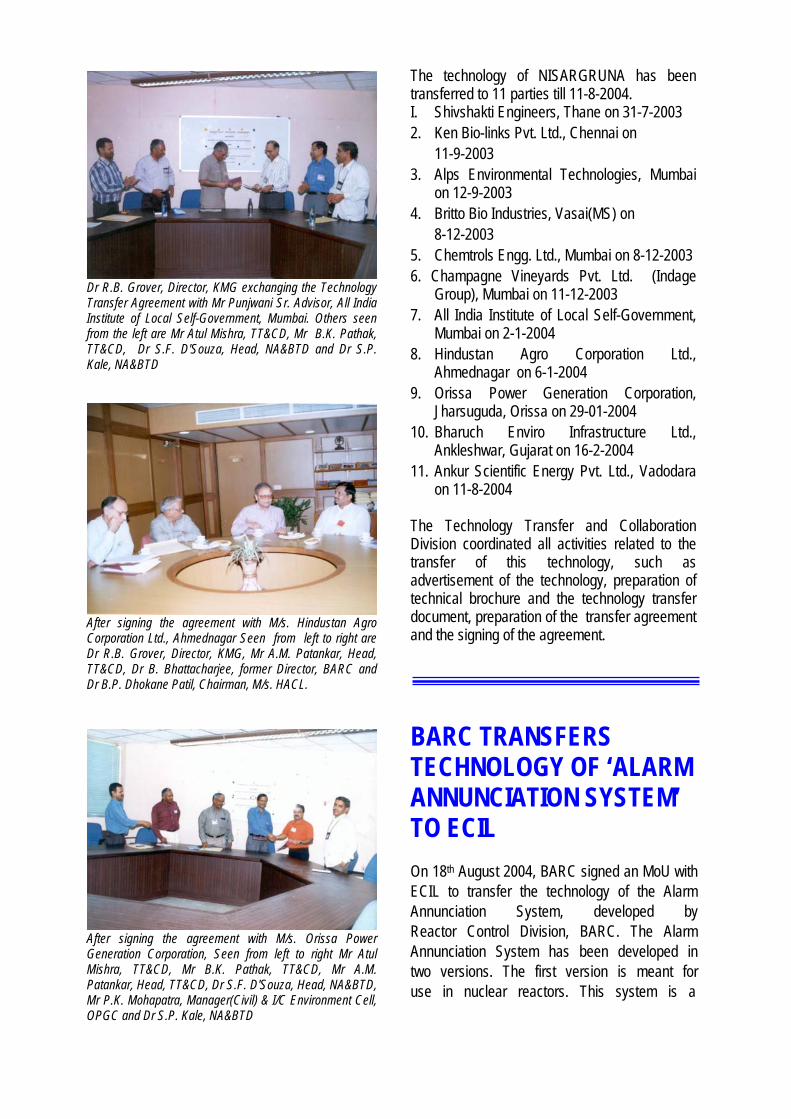
Dr R.B. Grover, Director, KMG exchanging the Technology Transfer Agreement with Mr Punjwani Sr. Advisor, All India Institute of Local Self-Government, Mumbai. Others seen from the left are Mr Atul Mishra, TT&CD, Mr B.K. Pathak, TT&CD, Dr S.F. D'Souza, Head, NA&BTD and Dr S.P. Kale, NA&BTD
After signing the agreement with M/s. Hindustan Agro Corporation Ltd., Ahmednagar Seen from left to right are Dr R.B. Grover, Director, KMG, Mr A.M. Patankar, Head, TT&CD, Dr B. Bhattacharjee, former Director, BARC and Dr B.P. Dhokane Patil, Chairman, M/s. HACL.
After signing the agreement with M/s. Orissa Power Generation Corporation, Seen from left to right Mr Atul Mishra, TT&CD, Mr B.K. Pathak, TT&CD, Mr A.M. Patankar, Head, TT&CD, Dr S.F. D'Souza, Head, NA&BTD, Mr P.K. Mohapatra, Manager(Civil) & I/C Environment Cell, OPGC and Dr S.P. Kale, NA&BTD

microcontroller-based system with distributed modular architecture and hot redundancy. It meets the category-IB requirements of nuclear reactor Alarm Annunciation System as per the guidelines laid down by AERB. It has additional features of self-diagnostics, communication, time stamping, printing etc. The system is committed
to three nuclear reactors in BARC. The second version which is also a microcontroller based distributed system, is for cost-conscious commercial users. With the transfer of this technology, ECIL will be in a position to meet the demands from nuclear reactor facilities as well as from commercial plants.
ž¸¸.œ¸.‚. ˆ½¿ÅÍ ˆ½Å ¨¸¾±¸¸¹›¸ˆÅ¸½¿ ˆÅ¸½ ¬¸ŸŸ¸¸›¸ / BARC SCIENTISTS HONOURED
ž¸¸ž¸¸ œ¸£Ÿ¸¸µ¸º ‚›¸º¬¸¿š¸¸›¸ ˆ½¿ÅÍ, Ÿ¸º¿¸ƒÄ, Ÿ¸½¿ ‚œ¾Ï¥¸ 15-16, 2004 ˆ½Å ™¸¾£¸›¸ ‚¸¡¸¸½¹¸÷¸ "”½¨¸¥¸œŸ¸½¿’ ƒ›¸ ƒÄ¸ú ‡›” Š¸¸Ÿ¸¸ £½¹”¡¸½©¸›¸ ’½Æ›¸|¥¸¸½¸ú œ¸£ ‡›¸‡‡‚¸£‚¸£‚¸ƒ ˆ½Å ¨¸¸¹«¸ÄˆÅ ¬¸ŸŸ¸½¥¸›¸ (‡›¸‡¬¸ú) Ÿ¸½¿
¨¸ú£½¿Í ˆºÅŸ¸¸£, ¨¸¸ƒ. ˆ½Å. ž¸¸£×¸¸, ‡¬¸. ‡›¸. ¸¸Ÿ¸™¸£ ‡¨¸¿ ‡¬¸. ¬¸ž¸£¨¸¸¥¸ ׸£¸ ¹¥¸¹‰¸÷¸ "œÏ¸½’ú›¸
(¸ú‡¬¸‡) ¸¸¿ƒ¹”¿Š¸ ¬’”ú¸ ‚|ûÅ £½¹”¡¸½©¸›¸ ŠÏ¸É’½” ¬¸½¥¡¸»¥¸¸½¸ Ÿ¸½¹’ïƬ¸ −½ë¨¸Š¸ ¹¨¸›¸¸ƒ¥¸¸½¿¸¸ƒÄ¥¸’︡¸¹Ÿ¸˜¸¸ƒÄ¥¸Ÿ¸¸½¹›¸¡¸Ÿ¸ ŠÏºœ¸" ›¸¸Ÿ¸ˆÅ ©¸¸½š¸ œ¸°¸ ˆÅú œ¸¸½¬’£ œÏ¬÷¸º¹÷¸ ˆÅ¸½ „¸ ˆÅ¸½¹’ ˆÅ¸ Ÿ¸¸›¸¸ Š¸¡¸¸— ©¸¸½š¸-œ¸°¸ ˆ½Å Ÿ¸º‰¡¸ ¥¸½‰¸ˆÅ ¨¸ú£½¿Í ˆºÅŸ¸¸£ ˆÅ¸½ ‡ˆÅ œÏ©¸¿¬¸›¸ú¡¸ œÏŸ¸¸µ¸œ¸°¸ ÷¸˜¸¸ ‡ˆÅ −¸¸£ ²œ¸‡ ˆÅú £¸¹©¸, œ¸º£¬ˆÅ¸£ ˆ½Å ³œ¸ Ÿ¸½¿ œÏ™¸›¸ ¹ˆÅ‡ Š¸‡— The paper entitled "Protein(BSA) binding studies of radiation grafted cellulose matrix having vinylbenzyltrimethylammonium group" authored
On the occasion of signing the MoU, seen from left to right are: Mr G.P. Srivastava, CMD, ECIL (holding technology documents), Mr Jose Joseph, RCnD, Mr Vikas Chauhan, RCnD, Mr G. Govindarajan, Director E&I and A&M groups, Mr R.K. Patil, Head, RCnD and Mr B.B. Biswas, RCnD

by Virendra Kumar, Y.K. Bhardwaj, S.N. Jamdar and S. Sabharwal was adjudged as best poster presentation at the NAARRI Annual Conference (NAC) on a Development in EB and Gamma Radiation Technology" held during April 15-16, 2004 at BARC, Mumbai. The first author of the paper Mr Virendra Kumar was awarded a merit certificate and Rs.1000/- (Rupees one thousand only) as cash award.
ýú ‚¹‰¸¥¸½©¸ ˆºÅŸ¸¸£ ¸¸¾£¹¬¸¡¸¸, ‚¸µ¸¹¨¸ˆÅ ¸ú¨¸-¹¨¸±¸¸›¸ œÏž¸¸Š¸, (œÏ¸¡¸¸½¹¸÷¸ œ¸¹£¡¸¸½¸›¸¸, ¸ú¨¸-œÏ¸¾Ô¸¸¾¹Š¸ˆÅú ¹¨¸ž¸¸Š¸) ›¸½ ûÅ£¨¸£ú 26-27,2004 ˆ½Å ™¸¾£¸›¸ œ¸ºµ¸½ ¹¨¸©¨¸¹¨¸Ô¸¸¥¸¡¸, œ¸ºµ¸½ ˆ½Å ž¸¸¾¹÷¸ˆÅú
¹¨¸ž¸¸Š¸ Ÿ¸½¿ 9¨¸ì £Ÿ¸µ¸ Ÿ¸½Ÿ¸¸½¹£¡¸¥¸ ¬¸ŸŸ¸½¥¸›¸ Ÿ¸½¿ ‡.ˆ½Å. ¸¸¾£¹¬¸¡¸¸, ‡.‡.œ¸¸£¬¸¹›¸¬¸ ‡¨¸¿ ‡¬¸. ˆ½Å. ‚¸œ’½ ׸£¸ ¹¥¸¹‰¸÷¸ "”½¨¸¥¸œŸ¸½¿’ ‚|ûÅ ’︿¬¸¸ú¹›¸ˆÅ ¬¸¸ƒ›¸¸½¸½Æ’ú¹£¡¸¥¸ ¬’ï½›¸¬¸ ¡¸»¹¸Š¿¸ ƒ¥¸½Æ’︽œ¸¸½£½©¸›¸ ’½Æ›¸úˆÅ" ©¸¸½š¸-œ¸°¸ ˆÅ¸½ œÏ¬÷¸º÷¸ ¹ˆÅ¡¸¸— ƒ¬¸ Ÿ¸¸¾¹‰¸ˆÅ œÏ¬÷¸º¹÷¸ ˆ½Å ¹¥¸‡ ƒ›−½¿ ¹×÷¸ú¡¸ œ¸º£¬ˆÅ¸£ ˆ½Å ³œ¸ Ÿ¸½¿ œ¸~¸ ¬¸¸¾ ²œ¸‡ ‡¨¸¿ ‡ˆÅ œÏŸ¸¸µ¸œ¸°¸ œÏ™¸›¸ ¹ˆÅ‡ Š¸‡— Mr Ahkhilesh Kumar Chaurasia, (JRF, working under a Dept. of Biotechnology - sponsored project in Molecular Biology Division), presented a paper entitled "Development of transgenic cyanobacterial strains using electroporation technique" authored by A.K. Chaurasia, A.A. Parasnis and S.K. Apte, at the IXth Raman Memorial Conference held at the Department of Physics, University of Pune, Pune, during February 26-27, 2004. His presentation fetched him the second prize of Rs. 500/- and a certificate.
ýúŸ¸÷¸ú −½Ÿ¸¸ £¸¸¸£¸Ÿ¸, ‚¸µ¸¹¨¸ˆÅ ¸ú¨¸-¹¨¸±¸¸›¸ œÏž¸¸Š¸, ›¸½ 20 Ÿ¸¸¸Ä 2004 ˆÅ¸½ ž¸¨¸›¸ Ÿ¸−¸¹¨¸Ô¸¸¥¸¡¸, ‚¿š¸½£ú, Ÿ¸º¿¸ƒÄ Ÿ¸½¿ ”|. š¸¸¥¸¸ ‚¹ž¸›¸¿™›¸ ˆÅ¸½«¸ ׸£¸
œÏ¸¡¸¸½¹¸÷¸ 12¨¸ì ¨¸¸¹«¸ÄˆÅ ©¸¸½š¸ œ¸°¸ œÏ¬÷¸º¹÷¸ Ÿ¸½¿ −½Ÿ¸¸ £¸¸¸£¸Ÿ¸ ‡¨¸¿ ‡¬¸ ˆ½Å ‚¸œ’½ ׸£¸ ¹¥¸¹‰¸÷¸ "›¸|¨¸½¥’ú¸ ‚|ûÅ −ú’-©¸|ˆÅ £½¬¸œ¸~¬¸ ƒ›¸ ¹™ ›¸¸ƒ’︽¸›¸ ¹ûŹƬ¸¿Š¸ ¬¸¸ƒ›¸¸½¸½Æ’ú¹£¡¸Ÿ¸ ‚¸›¸¸¸ú›¸¸ ‡¬¸œ¸ú. ¬’½ï¿›¸ ‡¥¸-31" ©¸ú«¸ÄˆÅ ©¸¸½š¸-œ¸°¸ œÏ¬÷¸º÷¸ ¹ˆÅ¡¸¸— „›¸ˆÅ¸ ©¸¸½š¸-œ¸°¸ œ¸ú‡¸.”ú. ý½µ¸ú Ÿ¸½¿ „¸ œÏ¬÷¸º¹÷¸ Ÿ¸¸›¸¸ Š¸¡¸¸ ÷¸˜¸¸ „›−½¿ œ¸º£¬ˆÅ¸£ ˆ½Å ³œ¸ Ÿ¸½¿ ‡ˆÅ −¸¸£ ²œ¸‡ ›¸ˆÅ™ ÷¸˜¸¸ ‡ˆÅ œÏŸ¸¸µ¸œ¸°¸ œÏ™¸›¸ ¹ˆÅ‡ Š¸‡— Ms Hema Rajaram of Molecular Biology Division presented a research paper entitled "Novelties of heat-shock response in the nitrogen fixing cyano-bacterium Anabaena sp. strain L-31" authored by Hema Rajaram and S.K. Apte, at the XIIth Annual Research Paper Presentation sponsored by Dr Dhala's Felicitation Fund in Bhavan's College, Andheri, Mumbai on March 20, 2004. Her paper was adjudged the best presentation in the Ph.D.category and was awarded a cash prize of Rs.1000/- and a certificate. ýú ¬¸¿¸¡¸ Ÿ¸¥−¸½°¸¸, ¹›¸¡¸¿°¸µ¸ ¡¸¿°¸úˆÅ£µ¸ œÏž¸¸Š¸, ž¸¸œ¸‚ ˆ½¿ÅÍ
ˆÅ¸½ ƒ¹›”¡¸›¸ ‚|ƒ¥¸ ˆÅ|£œ¸¸½£½©¸›¸ ˆÅú ž¸»¹Ÿ¸Š¸÷¸ ¹¸Žú −ºƒÄ œ¸¸ƒœ¸ ¥¸¸ƒ¿¬¸ ˆÅ¸ ‚¸¨¸¹š¸ˆÅ ƒ›¸-¥¸¸ƒ›¸ ¹›¸£ú®¸µ¸ ˆÅ£›¸½ −½÷¸º ƒ›¬’ñŸ¸½¿’” œ¸¸ƒœ¸¥¸¸ƒ›¸ ƒ›¬¸œ¸½Æ©¸›¸ Š¸½¸ ˆ½Å ¸º¿¸ˆÅú¡¸ Ÿ¸Á¸”ḻ¥¸ ˆÅ¸ ¹¨¸ˆÅ¸¬¸ ÷¸˜¸¸ œ¸¹£ˆÅ¥œ¸›¸
ˆÅ£›¸½ ˆ½Å ¹¥¸‡, ƒ¹›”¡¸›¸ ›¸¾©¸›¸¥¸ ‚ˆÅ¸™Ÿ¸ú ‚|ûÅ ƒ¿¸ú¹›¸¡¸ë£Š¸ ˆ½Å ¨¸«¸Ä 2003 ˆÅ¸ ¡¸º¨¸¸ ƒ¿¸ú¹›¸¡¸£ œ¸º£¬ˆÅ¸£ ¬¸½ ¬¸ŸŸ¸¸¹›¸÷¸ ¹ˆÅ¡¸¸ Š¸¡¸¸— Mr Sanjay Malhotra of Control Instrumentation Division, BARC was conferred the Young Engineer Award 2003 by the Indian National Academy of Engineering, for designing and developing the magnetic module of the Instrumented Pipeline Inspection Gauge, for periodic in-line inspection of buried pipelines, belonging to Indian Oil Corporation.
Edited and published by Dr Vijai Kumar, Head, Scientific Information Resource Division, Bhabha Atomic Research Centre, Trombay, Mumbai 400 085.
Editorial Management : S.C. Deokattey, Computer graphics & layout : N. Kanagaraj and P.A.S. Warrier, SIRD, BARC
BARC Newsletter is also available at URL:http://www.barc.ernet.in (for private circulation only)
Related Documents