ISSN(Online): 2319-8753 ISSN (Print): 2347-6710 International Journal of Innovative Research in Science, Engineering and Technology (An ISO 3297: 2007 Certified Organization) Website: www.ijirset.com Vol. 6, Issue 8, August 2017 Copyright to IJIRSET DOI:10.15680/IJIRSET.2017.0608246 16519 Design and Development of Kaplan Turbine Runner Blade Aadilahemad Momin 1 , Nairutya Dave 2 , Parth Patel 3 , Karan Panchal 4 Bachelor Student, Department of Mechanical Engineering, Navrachana University, Vadodara, Gujarat, India 1 Bachelor Student, Department of Mechanical Engineering, ITM Universe, Vadodara, Gujarat, India 2 Bachelor Student, Department of Mechanical Engineering, SVIT, Vasad, Gujarat, India 3 Bachelor Student, Department of Mechanical Engineering, GEC, Surat, Gujarat, India 4 ABSTRACT: Use of renewable energy has been of great interest since last few years, especially the hydropower energy. Usually electricity is generated from hydropower energy, which is obtained from potential pressure heads, water discharge and hydro sites. Based on the location constraints, different types of hydro turbines can be designed and developed to generate electricity. The primary concern is to reduce the dependency on fossil fuels and increase the use of renewable power in rural areas such as ChotaUdepur (Amalwant check dam). In this paper, designing of Kaplan turbine runner mechanism for Amalwant Check Dam(Vadodara) which has a head of 17m for the generation of power upto 5MW is carried out. For thickness calculation, occurring forces are established which is followed by detailed drawings of the developed runner mechanism drawn in SolidWorks 2014. KEYWORDS:Renewable Energy, Hydropower, Electricity, Kaplan Turbine, Check Dam, Design, Runner, SolidWorks I. INTRODUCTION Hydropower, generated mainly from hydroelectric dams, is a clear, green, and sustainable source of energy that produces cheaper electricity andlowers carbon emissions. Because of its high energy density, hydropower is the most efficient and most primarily available renewable power source to produce electricity [7]. In order to obtain greater efficiency, hydraulic turbines installed in the hydroelectric power plants have to be suitable, depending on the discharge of the site and head. There are a lot of hydraulic turbines available which are generally classified into two categories: 1] Impulse turbines 2] Reaction turbines A hydraulic turbine in which all hydraulic energy of water gets converted into kinetic energy before the water reaches to the runner of the turbine is called impulse turbine. While in case of reaction turbine, some amount of available hydraulic energy is converted into kinetic energy before it strikes on the runner of the turbine. For flow head range available at the chosen site, reaction turbine is well suited. Reaction turbines include Propeller, Kaplan, and Francis turbine [2]. Table 1 Classification of the Turbines Type Head Flow Rate Specific Speed Pelton Turbine High Low Low Francis Turbine Medium Medium Medium Kaplan Turbine Low High High

Welcome message from author
This document is posted to help you gain knowledge. Please leave a comment to let me know what you think about it! Share it to your friends and learn new things together.
Transcript
ISSN(Online): 2319-8753 ISSN (Print): 2347-6710
International Journal of Innovative Research in Science, Engineering and Technology
(An ISO 3297: 2007 Certified Organization)
Website: www.ijirset.com
Vol. 6, Issue 8, August 2017
Copyright to IJIRSET DOI:10.15680/IJIRSET.2017.0608246 16519
Design and Development of Kaplan Turbine Runner Blade
Aadilahemad Momin1, Nairutya Dave2, Parth Patel3, Karan Panchal4 Bachelor Student, Department of Mechanical Engineering, Navrachana University, Vadodara, Gujarat, India1
Bachelor Student, Department of Mechanical Engineering, ITM Universe, Vadodara, Gujarat, India2
Bachelor Student, Department of Mechanical Engineering, SVIT, Vasad, Gujarat, India3
Bachelor Student, Department of Mechanical Engineering, GEC, Surat, Gujarat, India4
ABSTRACT: Use of renewable energy has been of great interest since last few years, especially the hydropower energy. Usually electricity is generated from hydropower energy, which is obtained from potential pressure heads, water discharge and hydro sites. Based on the location constraints, different types of hydro turbines can be designed and developed to generate electricity. The primary concern is to reduce the dependency on fossil fuels and increase the use of renewable power in rural areas such as ChotaUdepur (Amalwant check dam). In this paper, designing of Kaplan turbine runner mechanism for Amalwant Check Dam(Vadodara) which has a head of 17m for the generation of power upto 5MW is carried out. For thickness calculation, occurring forces are established which is followed by detailed drawings of the developed runner mechanism drawn in SolidWorks 2014. KEYWORDS:Renewable Energy, Hydropower, Electricity, Kaplan Turbine, Check Dam, Design, Runner,
SolidWorks
I. INTRODUCTION Hydropower, generated mainly from hydroelectric dams, is a clear, green, and sustainable source of energy that produces cheaper electricity andlowers carbon emissions. Because of its high energy density, hydropower is the most efficient and most primarily available renewable power source to produce electricity [7]. In order to obtain greater efficiency, hydraulic turbines installed in the hydroelectric power plants have to be suitable, depending on the discharge of the site and head. There are a lot of hydraulic turbines available which are generally classified into two categories:
1] Impulse turbines 2] Reaction turbines
A hydraulic turbine in which all hydraulic energy of water gets converted into kinetic energy before the water reaches to the runner of the turbine is called impulse turbine. While in case of reaction turbine, some amount of available hydraulic energy is converted into kinetic energy before it strikes on the runner of the turbine. For flow head range available at the chosen site, reaction turbine is well suited. Reaction turbines include Propeller, Kaplan, and Francis turbine [2].
Table 1 Classification of the Turbines
Type Head Flow Rate Specific Speed
Pelton Turbine High Low Low
Francis Turbine Medium Medium Medium
Kaplan Turbine Low High High
ISSN(Online): 2319-8753 ISSN (Print): 2347-6710
International Journal of Innovative Research in Science, Engineering and Technology
(An ISO 3297: 2007 Certified Organization)
Website: www.ijirset.com
Vol. 6, Issue 8, August 2017
Copyright to IJIRSET DOI:10.15680/IJIRSET.2017.0608246 16520
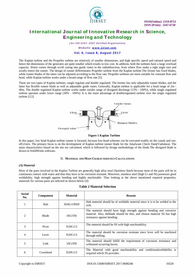
The Kaplan turbine and the Propeller turbine are relatively of smaller dimensions, and high specific speed and rational speed and hence the dimensions of the generator are quite smaller which results in low cost. In addition, both the turbines have a large overload capacity. Water comes through scroll casing into guide vanes in the radialdirection, from where flow make a right angle turn and axially enters the runner. The design of runner differentiates Propeller turbine from the Kaplan turbine.The former has fixed blades, while runner blades of the latter can be adjusted according to the flow rate. Propeller turbines are more suitable for constant flow and head, while Kaplan turbine works under a broad range of flow rate [5].
There are two types of Kaplan turbines: single regulate and double regulated. The former has only adjustable runner blades, and the latter has flexible runner blade as well as adjustable guide vanes. Generally, Kaplan turbine is applicable for a head range of 2m - 40m. The double regulated Kaplan turbine works under awider range of designed discharge (15% - 100%), while single regulated turbine operates under lower range (30% - 100%). It is the main advantage of doubleregulated turbine over the single regulated turbine [2,5].
Figure 1 Kaplan Turbine
In this paper, low head Kaplan turbine runner is focused, because low-head schemes can be executed readily on the canals and run-off-rivers. The primary focus is on the development of Kaplan turbine runner blade for the Amalwant Check Dam(Vadodara). The main characteristics based on the site are calculated, which is followed by design methodology of the blade.The designed blade is drawn in SolidWorks software.
II. MATERIAL AND MAIN CHARACTERISTICS CALCULATIONS (A) Material
Most of the parts involved in the Kaplan Turbine are generally high alloy steel (Stainless Steel) because most of the parts will be in continuous contact with water and thus they have to be corrosion resistant. Moreover, stainless steel (high Cr and Ni) possesses good weldability, high strength against bending and highly machinable. Thus looking at the above mentioned required properties, materials for various parts are selected as shown below [4]:
Table 2 Material Selection
Serial No. Component Material Reason
1 Hub X04Cr19Ni9 Hub material should be of weldable material since it is to be welded to the axle.
2 Blade 16Cr5Ni
The material should have high strength against bending and corrosive material. Also, theblade should be thin, and chosen material SS has high resistance against bending.
3 Pivot X20Cr13 The material should be SS with high machinability.
4 Lever X20Cr13 The material should be corrosion resistant since lever will be machined through milling.
5 Link 16Cr5Ni The material should fulfill the requirement of corrosion resistance and withstand occurring forces.
6 Crosshead X20Cr13 The Material with good machinability and conditionalweldability is required which SS provides.
ISSN(Online): 2319-8753 ISSN (Print): 2347-6710
International Journal of Innovative Research in Science, Engineering and Technology
(An ISO 3297: 2007 Certified Organization)
Website: www.ijirset.com
Vol. 6, Issue 8, August 2017
Copyright to IJIRSET DOI:10.15680/IJIRSET.2017.0608246 16521
(B) Main Characteristics Calculations
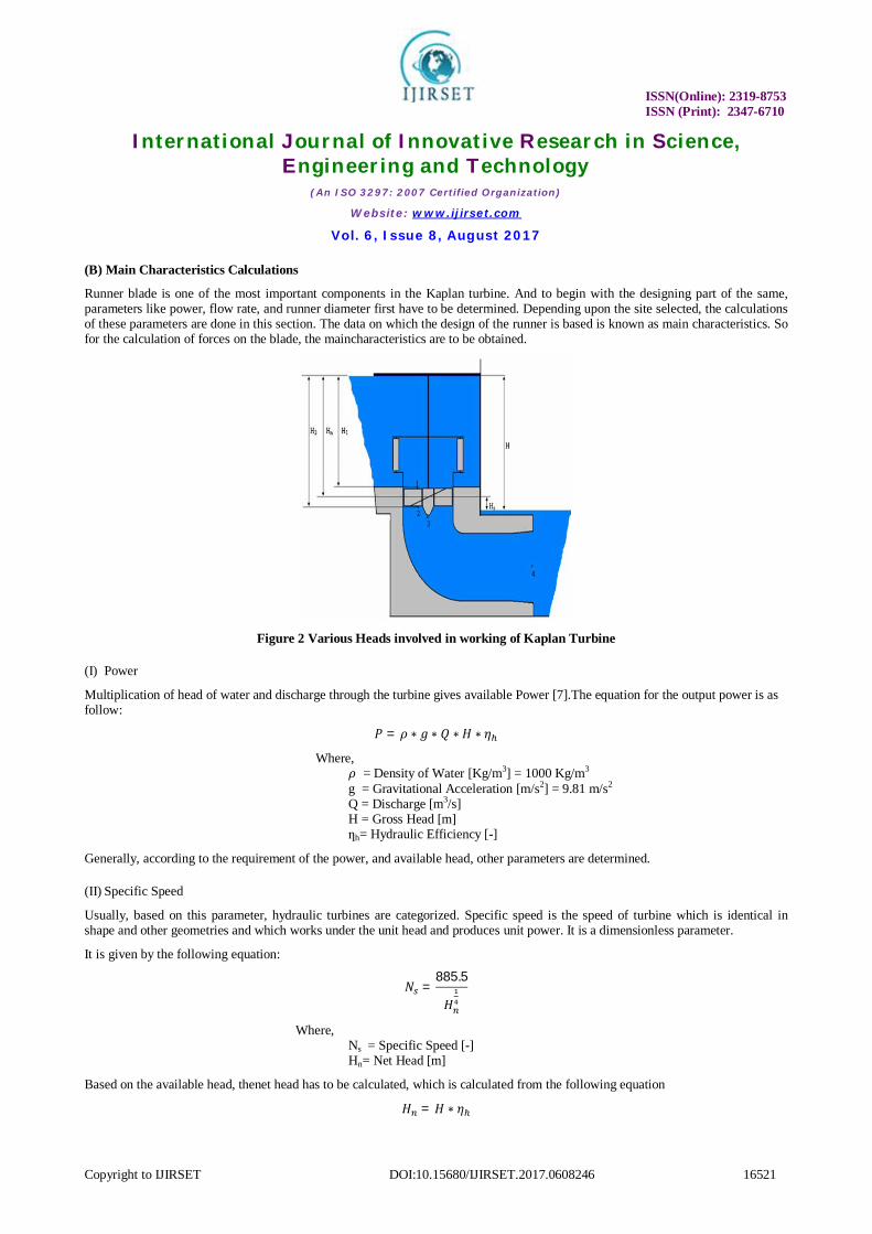
Runner blade is one of the most important components in the Kaplan turbine. And to begin with the designing part of the same, parameters like power, flow rate, and runner diameter first have to be determined. Depending upon the site selected, the calculations of these parameters are done in this section. The data on which the design of the runner is based is known as main characteristics. So for the calculation of forces on the blade, the maincharacteristics are to be obtained.
Figure 2 Various Heads involved in working of Kaplan Turbine
(I) Power
Multiplication of head of water and discharge through the turbine gives available Power [7].The equation for the output power is as follow:
푃 = 휌 ∗ 푔 ∗ 푄 ∗ 퐻 ∗ 휂
Where, 휌 = Density of Water [Kg/m3] = 1000 Kg/m3
g = Gravitational Acceleration [m/s2] = 9.81 m/s2 Q = Discharge [m3/s] H = Gross Head [m] ƞh= Hydraulic Efficiency [-]
Generally, according to the requirement of the power, and available head, other parameters are determined.
(II) Specific Speed
Usually, based on this parameter, hydraulic turbines are categorized. Specific speed is the speed of turbine which is identical in shape and other geometries and which works under the unit head and produces unit power. It is a dimensionless parameter.
It is given by the following equation:
푁 =885.5
퐻
Where, Ns = Specific Speed [-] Hn= Net Head [m]
Based on the available head, thenet head has to be calculated, which is calculated from the following equation
퐻 = 퐻 ∗ 휂
ISSN(Online): 2319-8753 ISSN (Print): 2347-6710
International Journal of Innovative Research in Science, Engineering and Technology
(An ISO 3297: 2007 Certified Organization)
Website: www.ijirset.com
Vol. 6, Issue 8, August 2017
Copyright to IJIRSET DOI:10.15680/IJIRSET.2017.0608246 16522
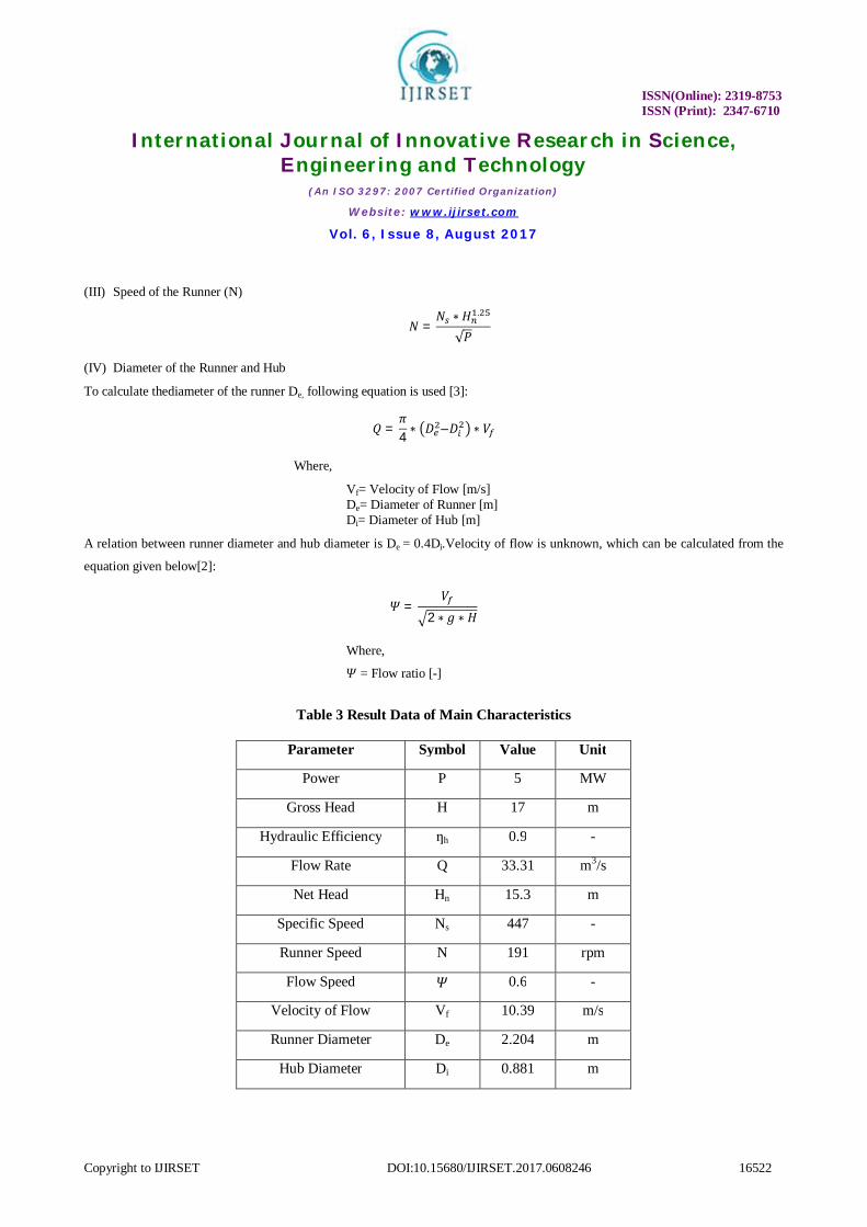
(III) Speed of the Runner (N)
푁 =푁 ∗ 퐻 .
√푃
(IV) Diameter of the Runner and Hub
To calculate thediameter of the runner De, following equation is used [3]:
푄 =휋4 ∗ 퐷 –퐷 ∗ 푉
Where,
Vf= Velocity of Flow [m/s] De= Diameter of Runner [m] Di= Diameter of Hub [m]
A relation between runner diameter and hub diameter is De = 0.4Di.Velocity of flow is unknown, which can be calculated from the
equation given below[2]:
훹 =푉
2 ∗ 푔 ∗ 퐻
Where,
훹 = Flow ratio [-]
Table 3 Result Data of Main Characteristics
Parameter Symbol Value Unit
Power P 5 MW
Gross Head H 17 m
Hydraulic Efficiency ƞh 0.9 -
Flow Rate Q 33.31 m3/s
Net Head Hn 15.3 m
Specific Speed Ns 447 -
Runner Speed N 191 rpm
Flow Speed 훹 0.6 -
Velocity of Flow Vf 10.39 m/s
Runner Diameter De 2.204 m
Hub Diameter Di 0.881 m

ISSN(Online): 2319-8753 ISSN (Print): 2347-6710
International Journal of Innovative Research in Science, Engineering and Technology
(An ISO 3297: 2007 Certified Organization)
Website: www.ijirset.com
Vol. 6, Issue 8, August 2017
Copyright to IJIRSET DOI:10.15680/IJIRSET.2017.0608246 16523
III. DESIGN METHODOLOGY The designing of the blade is mainly done in three parts. In the first part, the blade is considered to be a few sections. The radius of each section is to be calculated. Velocity diagram is drawn for each section, and involved velocities and blade angles of each section are calculated in the second part, While the thickness of the blade is calculated in the third part, once the occurring forces are established.In order to get a streamlined flow of water over the runner blade, the leading edge is designed thicker than the trailing edge. In addition, the cavitation characteristics can also be improved by keeping the blade as thin as possible; blade is designed so that thickness gradually reduces from the flange to the tip.
Figure 3Runner Blade
(I) Distortion of the Blade
As per this theory, the blade is considered to be distorted into six sections.The velocity triangles of six different sections of the blade are determined. The angle β∞ of each section gives conclusions on the distortion of the blade. Before beginning with the computation of the velocity triangle of each section of the blade, radiuses of each section needs to be determined.
Figure 4 Blade Sections
For Section 1,
R1 and hub radius (Ri) are same. So using Ri, radiusesof all the blade sections are calculated from following equations.
푅 = 푅
For Section 2,
푅 =퐷2 + 0.0015 ∗ 퐷
ISSN(Online): 2319-8753 ISSN (Print): 2347-6710
International Journal of Innovative Research in Science, Engineering and Technology
(An ISO 3297: 2007 Certified Organization)
Website: www.ijirset.com
Vol. 6, Issue 8, August 2017
Copyright to IJIRSET DOI:10.15680/IJIRSET.2017.0608246 16524
For Section 4,
푅 =퐷2 ∗
1 +
2
For Section 3,
푅 = 푅 + 푅 − 푅
2
For Section 6,
푅 =퐷2 − 0.015 ∗ 퐷
For Section 5,
푅 = 푅 + 푅 − 푅
2
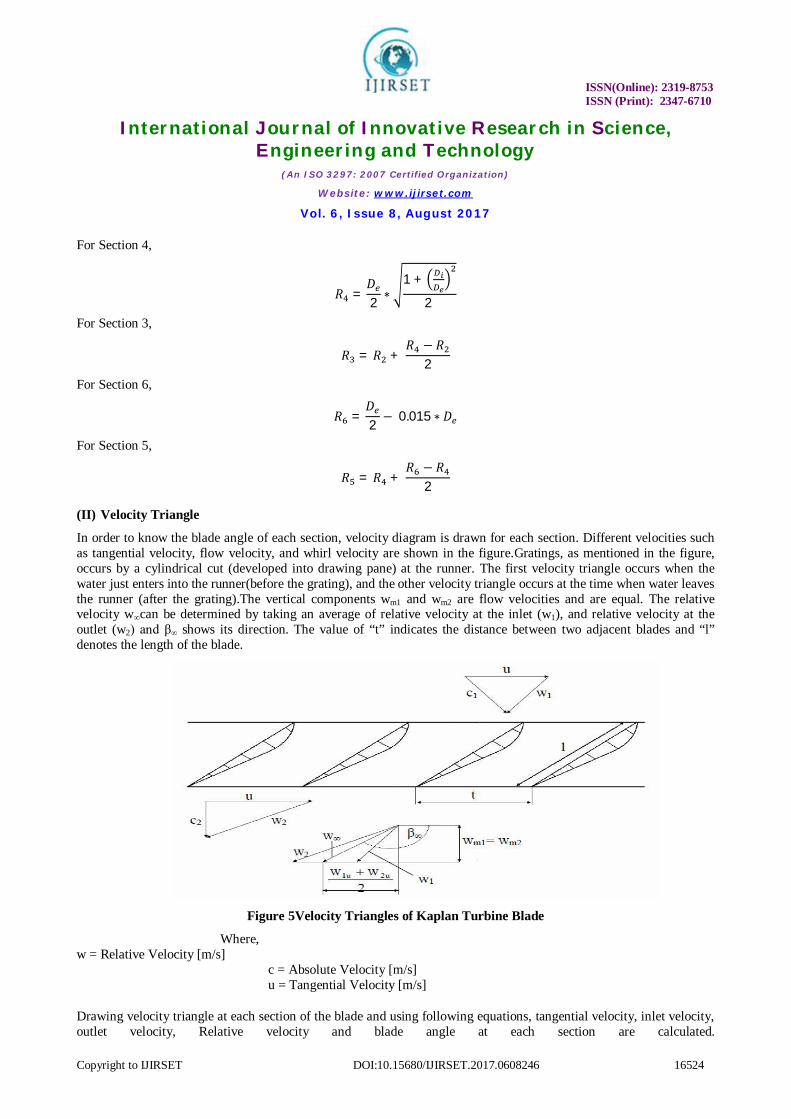
(II) Velocity Triangle
In order to know the blade angle of each section, velocity diagram is drawn for each section. Different velocities such as tangential velocity, flow velocity, and whirl velocity are shown in the figure.Gratings, as mentioned in the figure, occurs by a cylindrical cut (developed into drawing pane) at the runner. The first velocity triangle occurs when the water just enters into the runner(before the grating), and the other velocity triangle occurs at the time when water leaves the runner (after the grating).The vertical components wm1 and wm2 are flow velocities and are equal. The relative velocity w∞can be determined by taking an average of relative velocity at the inlet (w1), and relative velocity at the outlet (w2) and β∞ shows its direction. The value of “t” indicates the distance between two adjacent blades and “l” denotes the length of the blade.
Figure 5Velocity Triangles of Kaplan Turbine Blade
Where, w = Relative Velocity [m/s]
c = Absolute Velocity [m/s] u = Tangential Velocity [m/s]
Drawing velocity triangle at each section of the blade and using following equations, tangential velocity, inlet velocity, outlet velocity, Relative velocity and blade angle at each section are calculated.
ISSN(Online): 2319-8753 ISSN (Print): 2347-6710
International Journal of Innovative Research in Science, Engineering and Technology
(An ISO 3297: 2007 Certified Organization)
Website: www.ijirset.com
Vol. 6, Issue 8, August 2017
Copyright to IJIRSET DOI:10.15680/IJIRSET.2017.0608246 16525
Tangential Velocity,
푢 = 휋 ∗ 푑 ∗ 푛
Absolute Velocity,
푐 = 퐻 ∗ 푔푢
Whirl Velocity,
푤 = 푐 − 푢
Flow Velocity,
푤 =푄퐴
Relative Velocity,
푤 = 푤 + 푤
Blade Angle,
훽 = 푎푟푐푐표푠
푤푤
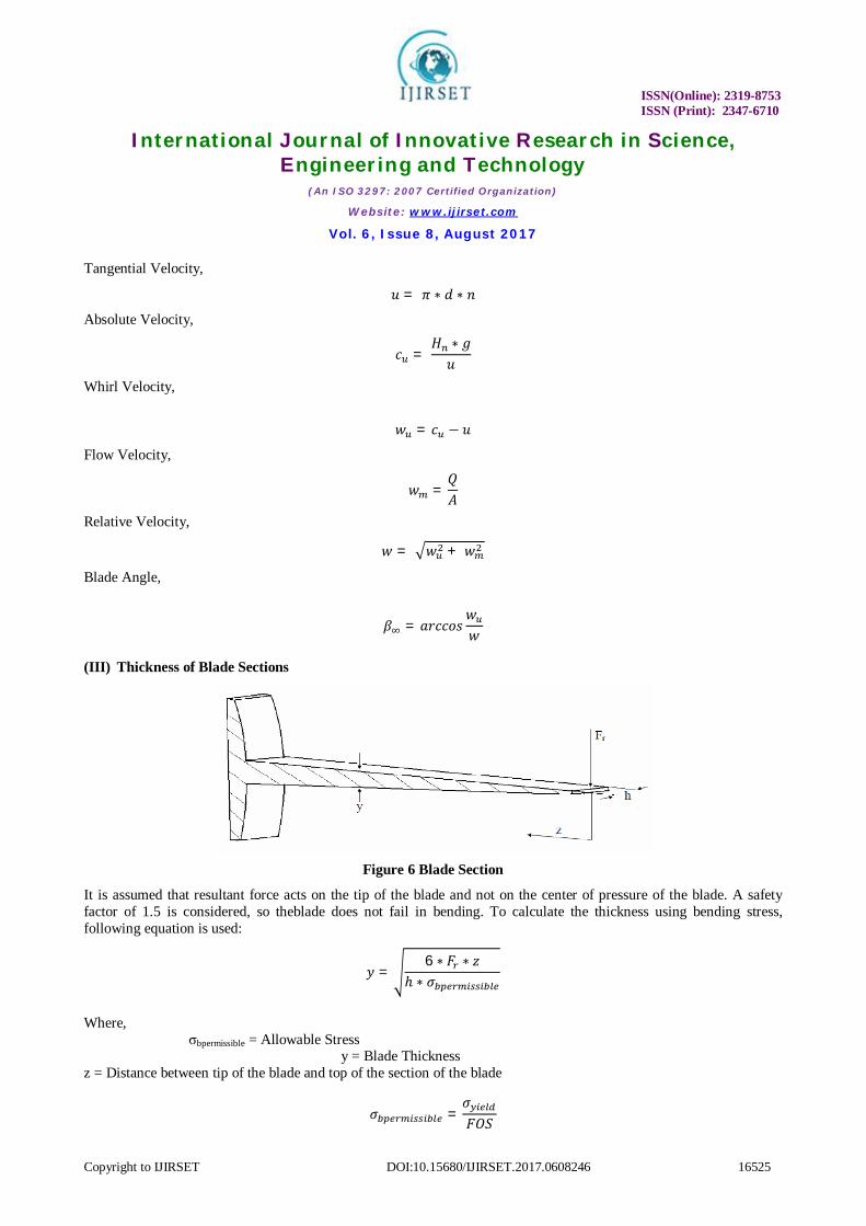
(III) Thickness of Blade Sections
Figure 6 Blade Section
It is assumed that resultant force acts on the tip of the blade and not on the center of pressure of the blade. A safety factor of 1.5 is considered, so theblade does not fail in bending. To calculate the thickness using bending stress, following equation is used:
푦 =6 ∗ 퐹 ∗ 푧
ℎ ∗ 휎
Where, σbpermissible = Allowable Stress y = Blade Thickness z = Distance between tip of the blade and top of the section of the blade
휎 =휎퐹푂푆

ISSN(Online): 2319-8753 ISSN (Print): 2347-6710
International Journal of Innovative Research in Science, Engineering and Technology
(An ISO 3297: 2007 Certified Organization)
Website: www.ijirset.com
Vol. 6, Issue 8, August 2017
Copyright to IJIRSET DOI:10.15680/IJIRSET.2017.0608246 16526
For thechosen material of the blade (16Cr5Ni), σyield = 750 MPa and factor of safety is taken as 1.5. So from above equation, σbpermissible yields out to be 500MPa. Distance z is found from the following equation:
푧 = 푅 −푅
Resultant Force,
퐹 = 퐹 + 퐹
Where,
Ft = Tangential Force [N] Fa = Axial Force [N]
Tangential force,
퐹 =푃
2 ∗ 휋 ∗ 푁 ∗ 푍 ∗ 푟
Where, N = Rotational Speed [rpm] Z = Number of Blade [-] rcp = Radius of the center of pressure [m]
Centre of pressure is a point on the blade on which the entire resultant force can be assumed to be acted and distance of which is calculated from the following equation:
푟 =푅 + 푅
2
Axial Force,
퐹 = 휌 ∗ 푔 ∗ 퐻 ∗ 퐴
Where, Ab= Area of the Blade
= ∗ ∗°
Table 4Result Data of Blade Profile
Parameter Unit 1 2 3 4 5 6 R m 0.473 0.656 0.839 0.954 1.068 1.102 L m 0.844 0.980 1.226 1.374 1.414 1.414 u m/s 9.50 13.16 16.83 19.13 21.43 20.86
wm m/s 10.39 10.39 10.39 10.39 10.39 10.39 wu m/s 15.79 11.39 8.91 7.84 7.00 6.83 cu m/s 18.90 15.42 17.81 13.02 14.78 12.45 w1 m/s 12.15 10.54 13.06 15.34 17.78 19.37 w2 m/s 14.08 16.77 19.78 21.77 23.82 25.29 w∞ m/s 13.11 13.66 16.42 18.56 20.80 22.33 β∞ º 127.55 130.42 140.71 145.92 150.01 152.00
180-β∞ º 52.44 49.57 39.28 34.07 29.98 28.00
ISSN(Online): 2319-8753 ISSN (Print): 2347-6710
International Journal of Innovative Research in Science, Engineering and Technology
(An ISO 3297: 2007 Certified Organization)
Website: www.ijirset.com
Vol. 6, Issue 8, August 2017
Copyright to IJIRSET DOI:10.15680/IJIRSET.2017.0608246 16527
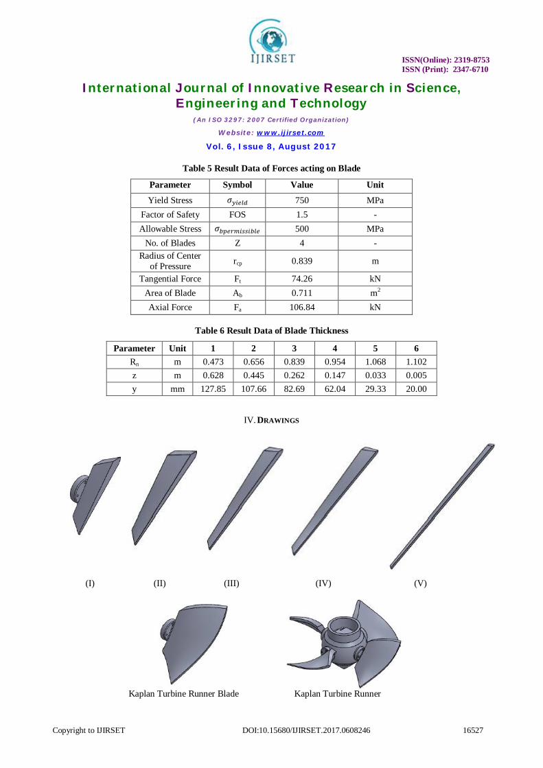
Table 5 Result Data of Forces acting on Blade
Parameter Symbol Value Unit
Yield Stress 휎 750 MPa Factor of Safety FOS 1.5 - Allowable Stress 휎 500 MPa
No. of Blades Z 4 - Radius of Center
of Pressure rcp 0.839 m
Tangential Force Ft 74.26 kN Area of Blade Ab 0.711 m2 Axial Force Fa 106.84 kN
Table 6 Result Data of Blade Thickness
Parameter Unit 1 2 3 4 5 6 Rn m 0.473 0.656 0.839 0.954 1.068 1.102 z m 0.628 0.445 0.262 0.147 0.033 0.005 y mm 127.85 107.66 82.69 62.04 29.33 20.00
IV. DRAWINGS
(I) (II) (III) (IV) (V)
Kaplan Turbine Runner Blade Kaplan Turbine Runner
ISSN(Online): 2319-8753 ISSN (Print): 2347-6710
International Journal of Innovative Research in Science, Engineering and Technology
(An ISO 3297: 2007 Certified Organization)
Website: www.ijirset.com
Vol. 6, Issue 8, August 2017
Copyright to IJIRSET DOI:10.15680/IJIRSET.2017.0608246 16528
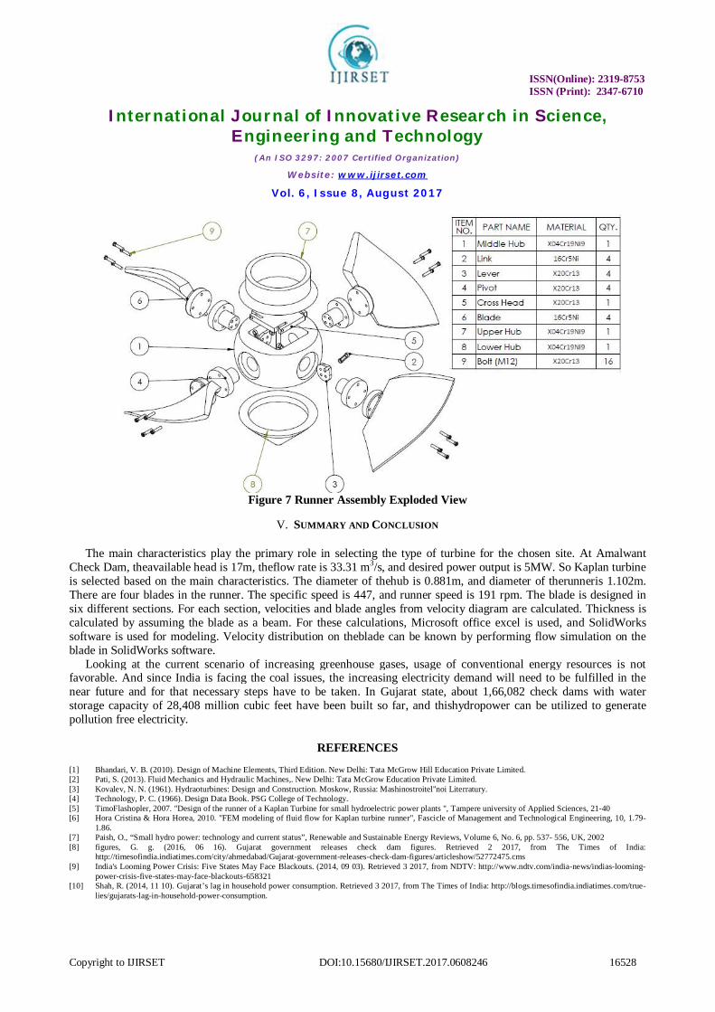
Figure 7 Runner Assembly Exploded View
V. SUMMARY AND CONCLUSION
The main characteristics play the primary role in selecting the type of turbine for the chosen site. At Amalwant Check Dam, theavailable head is 17m, theflow rate is 33.31 m3/s, and desired power output is 5MW. So Kaplan turbine is selected based on the main characteristics. The diameter of thehub is 0.881m, and diameter of therunneris 1.102m. There are four blades in the runner. The specific speed is 447, and runner speed is 191 rpm. The blade is designed in six different sections. For each section, velocities and blade angles from velocity diagram are calculated. Thickness is calculated by assuming the blade as a beam. For these calculations, Microsoft office excel is used, and SolidWorks software is used for modeling. Velocity distribution on theblade can be known by performing flow simulation on the blade in SolidWorks software.
Looking at the current scenario of increasing greenhouse gases, usage of conventional energy resources is not favorable. And since India is facing the coal issues, the increasing electricity demand will need to be fulfilled in the near future and for that necessary steps have to be taken. In Gujarat state, about 1,66,082 check dams with water storage capacity of 28,408 million cubic feet have been built so far, and thishydropower can be utilized to generate pollution free electricity.
REFERENCES
[1] Bhandari, V. B. (2010). Design of Machine Elements, Third Edition. New Delhi: Tata McGrow Hill Education Private Limited. [2] Pati, S. (2013). Fluid Mechanics and Hydraulic Machines,. New Delhi: Tata McGrow Education Private Limited. [3] Kovalev, N. N. (1961). Hydraoturbines: Design and Construction. Moskow, Russia: Mashinostroitel''noi Literratury. [4] Technology, P. C. (1966). Design Data Book. PSG College of Technology. [5] TimoFlashopler, 2007. "Design of the runner of a Kaplan Turbine for small hydroelectric power plants ", Tampere university of Applied Sciences, 21-40 [6] Hora Cristina & Hora Horea, 2010. "FEM modeling of fluid flow for Kaplan turbine runner", Fascicle of Management and Technological Engineering, 10, 1.79-
1.86. [7] Paish, O., “Small hydro power: technology and current status”, Renewable and Sustainable Energy Reviews, Volume 6, No. 6, pp. 537- 556, UK, 2002 [8] figures, G. g. (2016, 06 16). Gujarat government releases check dam figures. Retrieved 2 2017, from The Times of India:
http://timesofindia.indiatimes.com/city/ahmedabad/Gujarat-government-releases-check-dam-figures/articleshow/52772475.cms [9] India's Looming Power Crisis: Five States May Face Blackouts. (2014, 09 03). Retrieved 3 2017, from NDTV: http://www.ndtv.com/india-news/indias-looming-
power-crisis-five-states-may-face-blackouts-658321 [10] Shah, R. (2014, 11 10). Gujarat’s lag in household power consumption. Retrieved 3 2017, from The Times of India: http://blogs.timesofindia.indiatimes.com/true-
lies/gujarats-lag-in-household-power-consumption.
Related Documents