International OPEN ACCESS Journal Of Modern Engineering Research (IJMER) | IJMER | ISSN: 2249–6645 | www.ijmer.com | Vol. 4 | Iss. 5| May. 2014 | 37 | Design and Development of Arm Manikin for Blood Pressure and Pulse Simulation Mr. Mahavir K. Beldar 1 , Mr. Prasanna Balan 2 , Dr. B. B. Ahuja 3 1, 2, 3 (Mechatronics Engineering, Deputy Director, Production Engineering, Government College of Engineering Pune, India) I. Introduction 1.1 Introduction Using patient simulators in medical, nursing, and pharmacy education has increased. Simulators can be used as an effective teaching strategy to facilitate learning and improve knowledge, provide controlled and safe practice opportunities, and aid in the development of strong clinical skills. Patient simulators can range from using technology and volunteers portraying patients to high-fidelity full-body human patient simulators. Blood pressure simulator arm is among one simulator. Using the simulator arm is an acceptable method for teaching blood pressure measurement skills to students. The simulator arm allows a student to practice the same skills and techniques in measuring a blood pressure as executed on a human subject. Systolic and diastolic pressure, heart rate settings are adjusted using an external control panel allowing for variability, as seen in clinical practice. The simulator arm closely resembles a human subject's arm anatomically, therefore the proper application of the blood pressure cuff and stethoscope is necessary to measure successfully the blood pressure. 1.2 Need of Blood Pressure Measurement Simulator Arm This blood pressure simulator helps resolve the uncertainties common in teaching students to take blood pressure. This simulator allows the presetting of values for both systolic and diastolic pressures, provides an excellent means to practice listening to and distinguishing blood pressure sounds prior to actual clinical experience. Many times when working with a live subject, pressures are difficult to auscultate , making accurate evaluation of student proficiency almost impossible, and undermining the student’s self-confidence. With this realistic unit, the student can find the preset results and the instructor can unfailingly know if the student has performed the procedure accurately. Teacher can easily calibrate the unit for use with any sphygmomanometer. Advantages of Blood pressure simulator arm are as follows 1) Helps to resolve the uncertainties common in teaching students to take Blood Pressure. 2) Avoid the Fatigue coming on the patient due to frequently checking of Blood Pressure. 3) Avoids the bursting of Artery due to Excessive blood Pressure. Abstract: The purpose of this study is to develop an arm manikin for oscillometric methods of blood pressure measurement over full clinical range of blood pressure, heart rate. Blood pressure simulator helps to resolve the uncertainties common in teaching students to take blood pressure. Simulator allows the pre-setting of values for both systolic and diastolic pressures and provides an excellent means to practice listening and distinguishing blood pressure sounds prior to actual clinical experience. With this realistic unit, the student can find the preset results and the instructor can unfailingly know if the student has performed the procedure accurately. The arm manikin is a mould made up of rexine material which is coated with ethaflex as a skin material. A small rubber tube is used as blood vessel and a small micro-speaker for heart beat listening. An external electronic box is used to make students do the whole practice of blood pressure and pulse measurement. The compressed air with 2x2 NC solenoid valve and other pneumatic accessories are used to create the artificial pulses. A small micro-speaker with pre-recorded sound is used to generate heart beating sound in the antecubital area. A blood pressure sensor MPX5050GP is used to sense the sphygmomanometer dial pressure. PCB designed using a 16-bit micro-controller with on-chip ADC and DAC. It has five keys and graphical 16x2 LCD for setting the simulation parameters including the heart rate, systolic pressure, diastolic pressure. Keywords: Mechatronics System Design, Components Selection-Pressure Sensor, Solenoid Valve, μC, PCB Design.

Design and Development of Arm Manikin for Blood Pressure and Pulse Simulation
Nov 12, 2014
The purpose of this study is to develop an arm manikin for oscillometric methods of blood
pressure measurement over full clinical range of blood pressure, heart rate. Blood pressure
simulator helps to resolve the uncertainties common in teaching students to take blood pressure.
Simulator allows the pre-setting of values for both systolic and diastolic pressures and provides an
excellent means to practice listening and distinguishing blood pressure sounds prior to actual
clinical experience. With this realistic unit, the student can find the preset results and the instructor
can unfailingly know if the student has performed the procedure accurately. The arm manikin is a
mould made up of rexine material which is coated with ethaflex as a skin material. A small rubber
tube is used as blood vessel and a small micro-speaker for heart beat listening. An external electronic
box is used to make students do the whole practice of blood pressure and pulse measurement. The
compressed air with 2x2 NC solenoid valve and other pneumatic accessories are used to create the
artificial pulses. A small micro-speaker with pre-recorded sound is used to generate heart beating
sound in the antecubital area. A blood pressure sensor MPX5050GP is used to sense the
sphygmomanometer dial pressure. PCB designed using a 16-bit micro-controller with on-chip ADC
and DAC. It has five keys and graphical 16x2 LCD for setting the simulation parameters including
the heart rate, systolic pressure, diastolic pressure.
Welcome message from author
This document is posted to help you gain knowledge. Please leave a comment to let me know what you think about it! Share it to your friends and learn new things together.
Transcript

International
OPEN ACCESS Journal Of Modern Engineering Research (IJMER)
| IJMER | ISSN: 2249–6645 | www.ijmer.com | Vol. 4 | Iss. 5| May. 2014 | 37 |
Design and Development of Arm Manikin for Blood Pressure and
Pulse Simulation
Mr. Mahavir K. Beldar1, Mr. Prasanna Balan
2 , Dr. B. B. Ahuja
3
1, 2, 3 (Mechatronics Engineering, Deputy Director, Production Engineering, Government College of Engineering
Pune, India)
I. Introduction
1.1 Introduction
Using patient simulators in medical, nursing, and pharmacy education has increased. Simulators can be
used as an effective teaching strategy to facilitate learning and improve knowledge, provide controlled and safe practice opportunities, and aid in the development of strong clinical skills. Patient simulators can range from
using technology and volunteers portraying patients to high-fidelity full-body human patient simulators. Blood
pressure simulator arm is among one simulator. Using the simulator arm is an acceptable method for teaching
blood pressure measurement skills to students. The simulator arm allows a student to practice the same skills
and techniques in measuring a blood pressure as executed on a human subject. Systolic and diastolic pressure,
heart rate settings are adjusted using an external control panel allowing for variability, as seen in clinical
practice. The simulator arm closely resembles a human subject's arm anatomically, therefore the proper
application of the blood pressure cuff and stethoscope is necessary to measure successfully the blood pressure.
1.2 Need of Blood Pressure Measurement Simulator Arm
This blood pressure simulator helps resolve the uncertainties common in teaching students to take blood pressure. This simulator allows the presetting of values for both systolic and diastolic pressures, provides
an excellent means to practice listening to and distinguishing blood pressure sounds prior to actual clinical
experience. Many times when working with a live subject, pressures are difficult to auscultate , making accurate
evaluation of student proficiency almost impossible, and undermining the student’s self-confidence. With this
realistic unit, the student can find the preset results and the instructor can unfailingly know if the student has
performed the procedure accurately. Teacher can easily calibrate the unit for use with any sphygmomanometer.
Advantages of Blood pressure simulator arm are as follows
1) Helps to resolve the uncertainties common in teaching students to take Blood Pressure.
2) Avoid the Fatigue coming on the patient due to frequently checking of Blood Pressure.
3) Avoids the bursting of Artery due to Excessive blood Pressure.
Abstract: The purpose of this study is to develop an arm manikin for oscillometric methods of blood
pressure measurement over full clinical range of blood pressure, heart rate. Blood pressure
simulator helps to resolve the uncertainties common in teaching students to take blood pressure.
Simulator allows the pre-setting of values for both systolic and diastolic pressures and provides an excellent means to practice listening and distinguishing blood pressure sounds prior to actual
clinical experience. With this realistic unit, the student can find the preset results and the instructor
can unfailingly know if the student has performed the procedure accurately. The arm manikin is a
mould made up of rexine material which is coated with ethaflex as a skin material. A small rubber
tube is used as blood vessel and a small micro-speaker for heart beat listening. An external electronic
box is used to make students do the whole practice of blood pressure and pulse measurement. The
compressed air with 2x2 NC solenoid valve and other pneumatic accessories are used to create the
artificial pulses. A small micro-speaker with pre-recorded sound is used to generate heart beating
sound in the antecubital area. A blood pressure sensor MPX5050GP is used to sense the
sphygmomanometer dial pressure. PCB designed using a 16-bit micro-controller with on-chip ADC
and DAC. It has five keys and graphical 16x2 LCD for setting the simulation parameters including
the heart rate, systolic pressure, diastolic pressure.
Keywords: Mechatronics System Design, Components Selection-Pressure Sensor, Solenoid Valve,
µC, PCB Design.

Design and Development of Arm Manikin for Blood Pressure and Pulse Simulation
| IJMER | ISSN: 2249–6645 | www.ijmer.com | Vol. 4 | Iss. 5| May. 2014 | 38 |
1.3 Blood pressure measurement Method selected for making simulator The auscultator method (from the Latin word for "listening") uses a stethoscope and a
sphygmomanometer. Fig.1.1 shows the auscultatory method of blood pressure measurement. This comprises an inflatable cuff placed around the upper arm at roughly the same vertical height as the heart, attached to a
mercury or aneroid manometer. The mercury manometer, considered the gold standard, measures the height of a
column of mercury, giving an absolute result without need for calibration and, consequently, not subject to the
errors and drift of calibration which affect other methods. The use of mercury manometers is often required
in clinical trials and for the clinical measurement of hypertension in high-risk patients, such as pregnant women.
A cuff of appropriate size is fitted smoothly and snugly, and then inflated manually by repeatedly squeezing a
rubber bulb until the artery is completely occluded. Listening with the stethoscope to the brachial artery at
the elbow, the examiner slowly releases the pressure in the cuff. When blood just starts to flow in the artery,
the turbulent flow creates a "whooshing" or pounding (first Korotkoff sound). The pressure at which this sound
is first heard is the systolic blood pressure. The cuff pressure is further released until no sound can be heard
(fifth Korotkoff sound), at the diastolic arterial pressure. The auscultatory method is the predominant method of clinical measurement.
Fig.1.1 Auscultatory method aneroid sphygmomanometer with stethoscope
1.4 Medical Terms used in blood pressure measurement
Blood pressure-Blood pressure is the amount of force (pressure) that blood exerts on the walls of the
blood vessels as it passes through them.
1.4.1) Systolic pressure
Systolic blood pressure is a measure of blood pressure while the heart is beating. Systolic pressure is peak
pressure in the arteries, which occurs near the end of the cardiac cycle when the ventricles are contracting.
1.4.2) Diastolic pressure Diastolic pressure is a measure of blood pressure while the heart is relaxed. Diastolic pressure is the minimum
pressure in the arteries, which occurs near the beginning of the cardiac cycle when the ventricles are filled
with blood.
1.4.3) Pulse pressure
The up and down fluctuation of the arterial pressure results from the pulsatile nature of the cardiac output, i.e.
the heartbeat. The pulse pressure is determined by the interaction of the stroke volume of the heart, compliance
(ability to expand) of the aorta, and the resistance to flow in the arterial tree. By expanding under pressure, the
aorta absorbs some of the force of the blood surge from the heart during a heartbeat. In this way, the pulse
pressure is reduced from what it would be if the aorta wasn't compliant. The loss of arterial compliance that
occurs with aging explains the elevated pulse pressures found in elderly patients. The pulse pressure can be
simply calculated from the difference of the measured systolic and diastolic pressures. According to American
Heart Association the pulse pressure is given by,
1.5) Actual Procedure for Measuring Blood Pressure
Blood pressure is the amount of force (pressure) that blood exerts on the walls of the blood vessels as it
passes through them. Two pressures are required to be measure for a blood pressure reading:
1.5.1) Systolic blood pressure is a measure of blood pressure while the heart is beating
1.5.2) Diastolic pressure is a measure of blood pressure while the heart is relaxed, between heartbeats.
Blood pressure (BP), sometimes referred to as arterial blood pressure, is the pressure exerted by circulating
blood upon the walls of blood vessels. During each heartbeat, blood pressure varies between a maximum
Design and Development of Arm Manikin for Blood Pressure and Pulse Simulation
| IJMER | ISSN: 2249–6645 | www.ijmer.com | Vol. 4 | Iss. 5| May. 2014 | 39 |
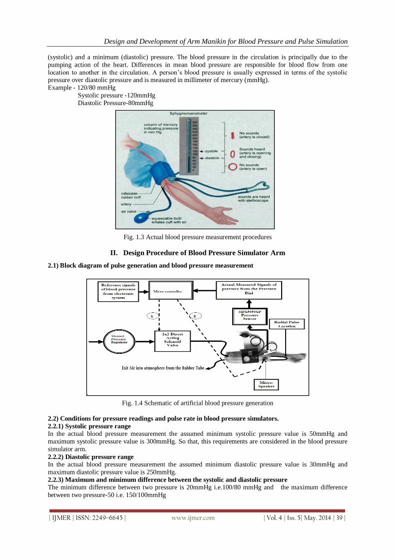
(systolic) and a minimum (diastolic) pressure. The blood pressure in the circulation is principally due to the
pumping action of the heart. Differences in mean blood pressure are responsible for blood flow from one
location to another in the circulation. A person’s blood pressure is usually expressed in terms of the systolic pressure over diastolic pressure and is measured in millimeter of mercury (mmHg).
Example - 120/80 mmHg
Systolic pressure -120mmHg
Diastolic Pressure-80mmHg
Fig. 1.3 Actual blood pressure measurement procedures
II. Design Procedure of Blood Pressure Simulator Arm
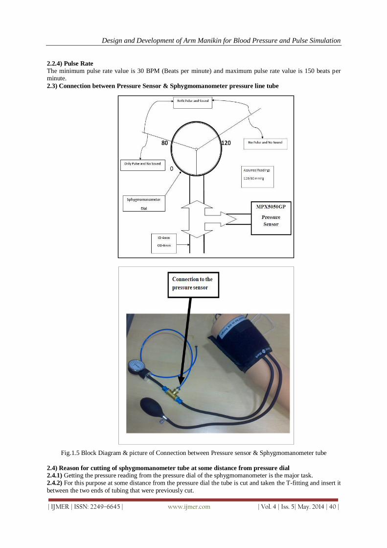
2.1) Block diagram of pulse generation and blood pressure measurement
Fig. 1.4 Schematic of artificial blood pressure generation
2.2) Conditions for pressure readings and pulse rate in blood pressure simulators.
2.2.1) Systolic pressure range
In the actual blood pressure measurement the assumed minimum systolic pressure value is 50mmHg and
maximum systolic pressure value is 300mmHg. So that, this requirements are considered in the blood pressure
simulator arm.
2.2.2) Diastolic pressure range
In the actual blood pressure measurement the assumed minimum diastolic pressure value is 30mmHg and
maximum diastolic pressure value is 250mmHg.
2.2.3) Maximum and minimum difference between the systolic and diastolic pressure
The minimum difference between two pressure is 20mmHg i.e.100/80 mmHg and the maximum difference
between two pressure-50 i.e. 150/100mmHg
Design and Development of Arm Manikin for Blood Pressure and Pulse Simulation
| IJMER | ISSN: 2249–6645 | www.ijmer.com | Vol. 4 | Iss. 5| May. 2014 | 40 |
2.2.4) Pulse Rate
The minimum pulse rate value is 30 BPM (Beats per minute) and maximum pulse rate value is 150 beats per minute.
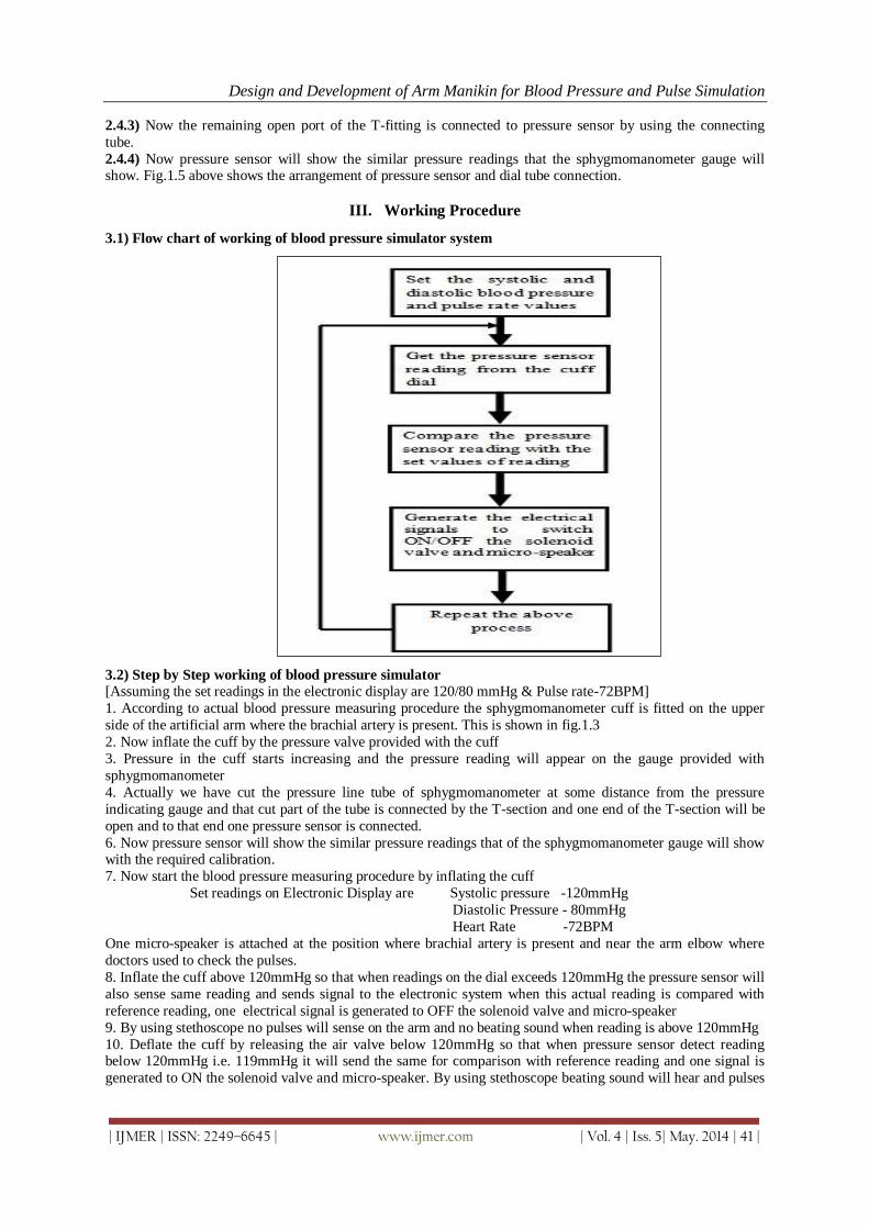
2.3) Connection between Pressure Sensor & Sphygmomanometer pressure line tube
Fig.1.5 Block Diagram & picture of Connection between Pressure sensor & Sphygmomanometer tube
2.4) Reason for cutting of sphygmomanometer tube at some distance from pressure dial
2.4.1) Getting the pressure reading from the pressure dial of the sphygmomanometer is the major task.
2.4.2) For this purpose at some distance from the pressure dial the tube is cut and taken the T-fitting and insert it
between the two ends of tubing that were previously cut.
Design and Development of Arm Manikin for Blood Pressure and Pulse Simulation
| IJMER | ISSN: 2249–6645 | www.ijmer.com | Vol. 4 | Iss. 5| May. 2014 | 41 |
2.4.3) Now the remaining open port of the T-fitting is connected to pressure sensor by using the connecting
tube.
2.4.4) Now pressure sensor will show the similar pressure readings that the sphygmomanometer gauge will show. Fig.1.5 above shows the arrangement of pressure sensor and dial tube connection.
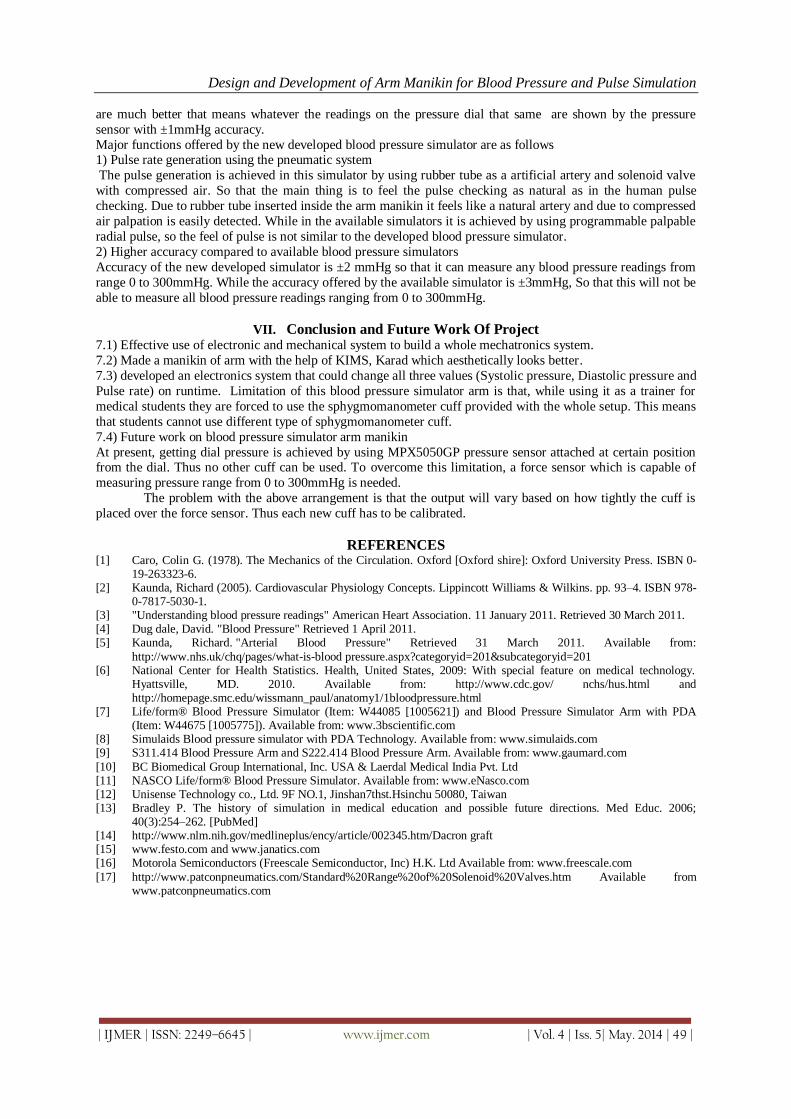
III. Working Procedure
3.1) Flow chart of working of blood pressure simulator system
3.2) Step by Step working of blood pressure simulator
[Assuming the set readings in the electronic display are 120/80 mmHg & Pulse rate-72BPM]
1. According to actual blood pressure measuring procedure the sphygmomanometer cuff is fitted on the upper
side of the artificial arm where the brachial artery is present. This is shown in fig.1.3
2. Now inflate the cuff by the pressure valve provided with the cuff
3. Pressure in the cuff starts increasing and the pressure reading will appear on the gauge provided with
sphygmomanometer
4. Actually we have cut the pressure line tube of sphygmomanometer at some distance from the pressure
indicating gauge and that cut part of the tube is connected by the T-section and one end of the T-section will be
open and to that end one pressure sensor is connected.
6. Now pressure sensor will show the similar pressure readings that of the sphygmomanometer gauge will show with the required calibration.
7. Now start the blood pressure measuring procedure by inflating the cuff
Set readings on Electronic Display are Systolic pressure -120mmHg
Diastolic Pressure - 80mmHg
Heart Rate -72BPM
One micro-speaker is attached at the position where brachial artery is present and near the arm elbow where
doctors used to check the pulses.
8. Inflate the cuff above 120mmHg so that when readings on the dial exceeds 120mmHg the pressure sensor will
also sense same reading and sends signal to the electronic system when this actual reading is compared with
reference reading, one electrical signal is generated to OFF the solenoid valve and micro-speaker
9. By using stethoscope no pulses will sense on the arm and no beating sound when reading is above 120mmHg
10. Deflate the cuff by releasing the air valve below 120mmHg so that when pressure sensor detect reading below 120mmHg i.e. 119mmHg it will send the same for comparison with reference reading and one signal is
generated to ON the solenoid valve and micro-speaker. By using stethoscope beating sound will hear and pulses

Design and Development of Arm Manikin for Blood Pressure and Pulse Simulation
| IJMER | ISSN: 2249–6645 | www.ijmer.com | Vol. 4 | Iss. 5| May. 2014 | 42 |
sensation. Now the pressure reading at the time when first heart beating sound hears is called as systolic
pressure.
12. Again deflate the cuff below 80mmHg i.e.79mmHg when sensor detect the same pressure reading and send it for comparison with reference reading and again system will generate one electrical signal to OFF the beating
sound(micro-speaker) and remains ON the solenoid valve. By using the stethoscope no beating sound will detect
and only pulse sensation takes place. Now the pressure reading at the time when last heat beating sound hears is
called as diastolic pressure. Above procedure will repeat for different set of pressure readings. Assuming the set
readings in the electronic display are 120/80 mmHg & Heart Rate-72BPM
3.3) Analogy of pulse and heart beating sound (Assuming the set readings in the electronic display are
120/80 mmHg & Pulse rate-72BPM)
Table 1.1 Analogy between pulse and heart beating
IV. Component's Selection
4.1) Selection of pressure sensor
4.1.1) Pressure sensor selection parameters
1) Range
The region between the limits within which an instrument is designed to operate for measuring, indicating or
recording a physical quantity is called the range of the instrument. So that required lower range of the sensor is
0mmHg and upper range is 300mmHg.Which is shown in fig.1.6
Fig.1.6 sphygmomanometer Dial
2) Resolution
The smallest amount of input signal change that the instrument can detect reliably. In the world of electronic
equipment, the term “resolution” refers to the measurement of the finest detail that can be resolved by the
sensors on a device. So that from the above picture of sphygmomanometer dial the sensor should be able to
measure minimum 2mmHg pressure.
3) Accuracy
The accuracy is a measure of the degree of closeness of a measured or calculated value to its actual value.
Accuracy required for the pressure sensor is ±1mmHg or less than ±0.33%FSS (full scale span) (Required full
scalespanis300mmHg)
4) Precision It prescribes the ability of the instrument to reproduce its readings over and over again for a constant input
signal. For the pressure sensor it must be as high as possible.

Design and Development of Arm Manikin for Blood Pressure and Pulse Simulation
| IJMER | ISSN: 2249–6645 | www.ijmer.com | Vol. 4 | Iss. 5| May. 2014 | 43 |
5) Sensitivity
Sensitivity of an instrument or an instrumentation system is the ratio of the magnitude of the response (output
signal) to the magnitude of the quantity being measured (input signal) i.e. Change of output signal
Sensitivity= ----------------------------
Change of input signal
The sensitivity for the sensor should be linear or almost constant over wide range of readings.
6) Mounting type
The sensor should be panel mountable or preferably on the printed circuit boards (PCB) mountable.
7) Electrical Specifications
7.1) Supply Voltage
As circuit design for blood pressure simulator arm is operating at 5Vdc .So that supply voltage required for the
sensor preferably 5Vdc supply.
7.2) Output Voltage The micro-controller (µC) used in the circuit design is operating in the voltage range of 0 to 5Vdc so that the
output of the sensor required for our application preferably in the volts (Vdc) instead of mill volts (mVdc).
4.1.2) Selected Pressure Sensor
The freescale semiconductors, Inc provides the MPX2050GP series device and it is a silicon piezoresistive
pressure sensor providing a highly accurate and linear voltage output directly proportional to the applied
pressure. The sensor is a single, monolithic silicon diaphragm with the strain gauge and a thin–film resistor
network integrated on–chip. The chip is laser trimmed for precise span and offset calibration and temperature
compensation.
Table 1.2. Operating Characteristic of pressure sensor [Model no.MPX2050GP]
.1.3) Works out calculations while selecting the pressure sensor are as follows
Minimum pressure measurement by the sensor should be 2mmHg. Let us calculate the resolution or the least
count as follows.
MPX5050GP pressure sensor is connected to port, which is an input to the on-chip 10-bit analog-to-
digital (A/D) converter. The pressure sensor provides a signal output to the microcontroller of approximately 0.2
Vdc at 0 mm Hg to 4.7 Vdc at 375 mm Hg of applied pressure. In this example, the input range of the A/D
converter is set at approximately 0 Vdc to 5Vdc. This compresses the range of the A/D converter around 0 mm
Hg to 300 mm Hg to maximize the resolution; 0 to 1023 counts is the range of the A/D converter. VRH and

Design and Development of Arm Manikin for Blood Pressure and Pulse Simulation
| IJMER | ISSN: 2249–6645 | www.ijmer.com | Vol. 4 | Iss. 5| May. 2014 | 44 |
VRL are the reference voltage inputs to the A/D converter. Vensor is output of the sensor. The resolution is
defined by the following:
Count = [(Vsensor - VRL) / (VRH - VRL)] x 1023 The count at 0 mmHg = [(0.2 - 0)/ (5.0 - 0)] x 1023 =40.92≈ 41
The count at 300 mmHg = [(5.0 - 0)/ (5.0 - 0)] x 1023 ≈ 1023
Therefore the resolution = 1023-41 = 982 counts.
This translates to a system that will resolve to [300/982] 0.3054 mmHg. That is the sensor is used to measure
0.3054 mmHg minimum pressure so this MPX5050GP sensor is selected. The output of the pressure sensor is
ratio metric to the voltage applied to it. Resolution= 0.3054 mmHg So that, the resolution of the selected sensor
is 0.3054 mmHg which will be rounded to 1mmHg in the electronic system
5.3) Selection of other pneumatic Accessories
5.3.1) Requirement of the solenoid valve in the blood pressure simulator arm
Reason for the use of the solenoid valve in the blood pressure simulator arm is to generate the
artificial pulse with the use of electronic delay signals & which will be felt at the wrist location of the hand. Assuming the maximum and minimum heart beats of the human in the range of 40 to 140 beats per minute
(BPM) so that accordingly solenoid valve is selected and having response time in the range of 0.42(for 140
beats) to 1.5(for 40 beats) second. After studying the specifications of different types of solenoid valves, the
patcon pneumatics solenoid valve model number is PC22CD selected.
5.3.2) Details of the solenoid valve model PC22CD
Patcon Pneumatics offers Direct Acting 2/2 Way NC Solenoid Valve. Patcon Pneumatics supplies
pneumatic systems and equipments in wide ranges. Direct Acting 2/2 Way NC Solenoid Valve is applied in
various sectors like- water treatment plants, nuclear power plants, domestic water purifiers, thermal power
plants, welding industry and packaging industry etc. Direct Acting 2/2 Way NC Solenoid Valve is suited with 0-
40 Bar pressure. Direct Acting 2/2 Way NC Solenoid Valve requires 1/8 inch to 1/2 inch BSP/NPT connections.
5.3.2a) Specifications of the solenoid valve 1) Operating pressure range- 0 to 10Bar
2) Coil Voltage- 24Vdc
3) Coil rating- Continuous duty rated
4) Fluids- Air, Inert gas.
5.3.2b) Technical Specifications of Direct Acting 2/2 Way NC Solenoid Valve
Table No. 1.3 Technical Specification of solenoid valve
5.4) Selection of the connectors and Tubes

Design and Development of Arm Manikin for Blood Pressure and Pulse Simulation
| IJMER | ISSN: 2249–6645 | www.ijmer.com | Vol. 4 | Iss. 5| May. 2014 | 45 |
In order to connect the pneumatic nylon tubes with pressure regulator, solenoid valve and finally to the
rubber tube which is artificial artery we require some pneumatic connectors and which are listed below. For our
application we have selected and used nylon tubes having sizes are 8x6 mm and 4x2 mm.
Table No.1.4 Selected connectors and tubes
5.5) Electronic components selection
5.5.1) Transformer
The Transformer used here is a 18-0-18 centre tap transformer which gives a final output of 36 V AC output.
As we know that
VRMS = VPeak /√2 The value here comes here to be 25.455 V sufficient inputs for a 24 V output of LM317.
5.5.2) Rectifier circuit
The rectifier circuit used here is commonly used when its output is to be fed to a linear regulator. The circuit
here uses a centre tap transformer with two diodes to give a pulsating DC signal. This then is fed into a series of
caps into a linear regulator. This technique is very simple and easy to build.
Fig.1.7 Rectifier circuit
5.5.3) linear regulators
Linear regulator ICs are used primarily for regulating DC voltages. These are primarily used for getting a
fixed/variable voltage when power losses are not much of a concern. Various power regulator ICs are available depending on power losses and voltage levels. The generic diagram of a power regulator is as below:
Fig.1.8 Basic operation of linear power regulator

Design and Development of Arm Manikin for Blood Pressure and Pulse Simulation
| IJMER | ISSN: 2249–6645 | www.ijmer.com | Vol. 4 | Iss. 5| May. 2014 | 46 |
As you can see, Vin is the input voltage and Vout or voltage across RL is the output voltage. The op-amp sees to
it that voltage on both its inputs remains the same. This causes output to be equal to VREF. In fixed voltage regulators like the 78xx series, the reference voltage is fixed whereas in ICs like LM317 and so on, reference
voltage is also variable and is set using a pair of resistances.
Fig.1.9 LM317 IC
Varying values of R2 gives different values at output. Changing the output value only means changing 1 (at
most 2) resistances.
5.3.4) Micro-controller
The micro-controller is the heart of the circuit. It is technically a mini-computer which can be programmed and
used in such smaller circuits. It has an internal RAM, ROM, ALU and peripherals that are used in getting the
work done. There are many different companies manufacturing different types of micros. Popular amongst them are Microchip, Atmel, Parallax, Motorola etc. The micro-controller that we are using here is Atmega 16.
It's specifications are:
1. 8 bit CPU. This also means 8 bit ALU
2. 16 KB Internal Flash
3. 512 Bytes EEPROM
4. 1KB Internal SRAM
5. In System Programming Feature
6. Two 8 bit Timer/Counter and 1 16 Bit Timer/Counter with PWM
7. 8 channel 10 bit ADC
8. External and Internal Interrupt sources
9. 9. 32 programmable I/O lines 10. Support for USART and slave/master SPI
5.3.5) L293D IC
It is the most commonly used motor control driver IC. It is very highly used for controlling 2 DC motors or a
single stepper motor. It is a very versatile tool and can be used wherever current limit is about 1.2 A. The main
reason why such motor drivers are needed is because motors need a lot of current. The average current
consumption of a micro is less than 100mA. That’s not enough for a motor to rotate. Motor driver ICs have 2
sets of input voltages, supply voltage and logic supply voltage.
For L293D it is as below:
Max Supply Voltage: 36V
Max Logic Supply Voltage: anything from about 1.5V to supply voltage
Max Enable Voltage: 7V Based on the logic voltage input and enable pin, supply voltage is given to the motors. Logic
voltage can be taken from the micro-controller. In this way, motors can be controlled by a micro. It is this
feature that makes these devices useful.
5.3.6) 16x2 LCD display
This display is used here to set the input and output and also as a tool for debugging in case some things go
wrong. It has 2 lines of display, 16 characters per line. Hence, the name is 16x2. There are a lot of varieties of
this display available. All of them use the IC HD44780 from Hitachi.

Design and Development of Arm Manikin for Blood Pressure and Pulse Simulation
| IJMER | ISSN: 2249–6645 | www.ijmer.com | Vol. 4 | Iss. 5| May. 2014 | 47 |
Fig 2.0 16X2 LCD Display
This display has: 1. 8 bit data bus. It can be used in 8 bit or 4 bit mode.
2. 3 control pins
1. Enable pin to enable/disable the display
2. R/S pin to set whether command or data
3. RW pin to set whether to read or write to the LCD
3. 2 back light pins
4. 1 contrast pin to set contrast of output displayed
5. VCC and GND power inputs
5.4) Micro-controller ADC considerations and Works out calculations
There is one component of any system that is very important and must be studied in detail when using any such
sensor that outputs analog data, ADC. Every processor or computer based circuit needs to have an ADC because computers/micros work in the digital world whereas sensors still work in the analog world. Atmega 16 has a 10
bit ADC. This basically means that the whole range is divided into 0 to 2^10-1 (i.e.) 1023 levels. In the case of
this project, overall voltage level is 0-5V.
Thus, 1 level= 5V/1023 = 4.88 mV .Thus, the least count of ADC should be more than 4.88 mV otherwise the
ADC cannot show correct readings. Our least count of pressure is 2mm Hg as the dial cannot show 1 mm Hg.
Hence, least count of the sensor must be 4.88mV/2mmHg (i.e.) 2.44mV/mm Hg or less.
Also, care should be taken that multiple values don't round up to the same actual value. This care is taken here in
the code.
5.5) Code for micro-controller
Code is compiled using avr-gcc and burnt using avrdude.
V. PCB Design And Complete Circuit Board
The diagram and the schematic have been made using eagle software. The board uses Eagle’s maximum size of
10 cm by 8 cm. This is a single layer board full of through hole components.
Fig2.1 PCB Design and Complete circuit

Design and Development of Arm Manikin for Blood Pressure and Pulse Simulation
| IJMER | ISSN: 2249–6645 | www.ijmer.com | Vol. 4 | Iss. 5| May. 2014 | 48 |
Fig.2.2 Complete arm manikin setup
VI. Sensor Testing and Results
Calculations and graph plotting of sensor output voltage Vs Input pressure applied- Checking of the
sensor output voltage with input pressure applied is very necessary. Transfer function for the output voltage provided by the freescale semiconductor Inc; is given by,
Vout = Vs (P x 0.018+0.04)
Whereas, Vout- Output voltage of the sensor in Volts
Vs- Supply voltage to the sensor in Volts
P- Input pressure to the sensor in kPa
From the transfer function, Values of the actual output voltage of the sensor and measured output voltage of the
sensor with input pressure are calculated as below.
Table1.4 Reading and Graph of Sensor output voltage (V) Vs Input pressure (kPa)
Repeatability of the blood pressure readings are explained below-
Above graph clearly shows that the true values and measured values of sensor output voltage coincides except some deviation. Above graph is plotted for 0 to 300mmHg pressure range (i.e.0 to 40kPa) on X-axis and
Sensor output voltage range 0.2 to 3.8V on Y-axis. The deviation in the output voltage occurs or rather graph is
non-linear at the pressure points 5kPa (37.5mmHg), 10kPa (75mmHg), 35kPa (262.5mmHg).As this is the direct
output measured from the pressure sensor with digital-multimeter (DMM). When pressure sensor output signal
is interfaced with the micro-controller (µc) with proper analog to digital conversion (ADC) the results obtained
Design and Development of Arm Manikin for Blood Pressure and Pulse Simulation
| IJMER | ISSN: 2249–6645 | www.ijmer.com | Vol. 4 | Iss. 5| May. 2014 | 49 |
are much better that means whatever the readings on the pressure dial that same are shown by the pressure
sensor with ±1mmHg accuracy.
Major functions offered by the new developed blood pressure simulator are as follows 1) Pulse rate generation using the pneumatic system
The pulse generation is achieved in this simulator by using rubber tube as a artificial artery and solenoid valve
with compressed air. So that the main thing is to feel the pulse checking as natural as in the human pulse
checking. Due to rubber tube inserted inside the arm manikin it feels like a natural artery and due to compressed
air palpation is easily detected. While in the available simulators it is achieved by using programmable palpable
radial pulse, so the feel of pulse is not similar to the developed blood pressure simulator.
2) Higher accuracy compared to available blood pressure simulators
Accuracy of the new developed simulator is ±2 mmHg so that it can measure any blood pressure readings from
range 0 to 300mmHg. While the accuracy offered by the available simulator is ±3mmHg, So that this will not be
able to measure all blood pressure readings ranging from 0 to 300mmHg.
VII. Conclusion and Future Work Of Project
7.1) Effective use of electronic and mechanical system to build a whole mechatronics system.
7.2) Made a manikin of arm with the help of KIMS, Karad which aesthetically looks better.
7.3) developed an electronics system that could change all three values (Systolic pressure, Diastolic pressure and
Pulse rate) on runtime. Limitation of this blood pressure simulator arm is that, while using it as a trainer for
medical students they are forced to use the sphygmomanometer cuff provided with the whole setup. This means
that students cannot use different type of sphygmomanometer cuff.
7.4) Future work on blood pressure simulator arm manikin
At present, getting dial pressure is achieved by using MPX5050GP pressure sensor attached at certain position from the dial. Thus no other cuff can be used. To overcome this limitation, a force sensor which is capable of
measuring pressure range from 0 to 300mmHg is needed.
The problem with the above arrangement is that the output will vary based on how tightly the cuff is
placed over the force sensor. Thus each new cuff has to be calibrated.
REFERENCES [1] Caro, Colin G. (1978). The Mechanics of the Circulation. Oxford [Oxford shire]: Oxford University Press. ISBN 0-
19-263323-6. [2] Kaunda, Richard (2005). Cardiovascular Physiology Concepts. Lippincott Williams & Wilkins. pp. 93–4. ISBN 978-
0-7817-5030-1. [3] "Understanding blood pressure readings" American Heart Association. 11 January 2011. Retrieved 30 March 2011. [4] Dug dale, David. "Blood Pressure" Retrieved 1 April 2011. [5] Kaunda, Richard. "Arterial Blood Pressure" Retrieved 31 March 2011. Available from:
http://www.nhs.uk/chq/pages/what-is-blood pressure.aspx?categoryid=201&subcategoryid=201 [6] National Center for Health Statistics. Health, United States, 2009: With special feature on medical technology.
Hyattsville, MD. 2010. Available from: http://www.cdc.gov/ nchs/hus.html and http://homepage.smc.edu/wissmann_paul/anatomy1/1bloodpressure.html
[7] Life/form® Blood Pressure Simulator (Item: W44085 [1005621]) and Blood Pressure Simulator Arm with PDA (Item: W44675 [1005775]). Available from: www.3bscientific.com
[8] Simulaids Blood pressure simulator with PDA Technology. Available from: www.simulaids.com [9] S311.414 Blood Pressure Arm and S222.414 Blood Pressure Arm. Available from: www.gaumard.com
[10] BC Biomedical Group International, Inc. USA & Laerdal Medical India Pvt. Ltd [11] NASCO Life/form® Blood Pressure Simulator. Available from: www.eNasco.com [12] Unisense Technology co., Ltd. 9F NO.1, Jinshan7thst.Hsinchu 50080, Taiwan [13] Bradley P. The history of simulation in medical education and possible future directions. Med Educ. 2006;
40(3):254–262. [PubMed] [14] http://www.nlm.nih.gov/medlineplus/ency/article/002345.htm/Dacron graft [15] www.festo.com and www.janatics.com [16] Motorola Semiconductors (Freescale Semiconductor, Inc) H.K. Ltd Available from: www.freescale.com
[17] http://www.patconpneumatics.com/Standard%20Range%20of%20Solenoid%20Valves.htm Available from www.patconpneumatics.com
Related Documents