18 Design and Development of an Unmanned Surveillance Aerial Vehicle (USAV) Using Locally Sourced Materials Basil Akinnuli, Olayinka Oluwole Agboola, Peter Pelumi Ikubanni An Unmanned Surveillance Aerial Vehicle (USAV) is an air vehicle which is largely used for surveillance, monitoring, reconnaissance, data relay, and data collection or to enter an area which is not safe for human. This study documents the development and evaluation of a low cost, short range unmanned aerial vehicle to monitor a fixed operational urban area. Aerodynamic principles were employed to develop a better concept through reasonable design considerations and assumptions. The design was then modeled using National Aeronautics and Space Administration (NASA) Vehicle Sketch Pad (VSP). Analysis of aerodynamic properties of the wing airfoil section, lift and drag analysis of resisting surfaces, stability in flight were carried out with the aid of Computational Fluid dynamics software (JAVA FOIL). Ultimately, in achieving the goal of this study, the design concept was supported by the fabrication of a flying prototype. Keywords: Aerial Vehicle, Surveillance, Aerodynamic, JAVA Foil, Airfoil 1. Introduction An Unmanned Aerial Vehicle (UAV), as a type of aircraft, has no onboard crew or passengers. They can either be autonomous drones or remotely piloted vehicles (RPVs). A UAV is capable of controlled, sustained level flight and is powered by a jet, reciprocating, or electric engine. Although, UAVs are a relatively modern concept, their origin dates back to pre-aviation times, the earliest application being surveillance and warfare (NOVA, 2014). Aerial reconnaissance has always been an essential feature of military intelligence. The first use of aircraft in a military context was as artillery spotter planes at the start of World War I (Ian, 2013). Surveillance has subsequently been more safely undertaken by sophisticated and expensive satellite systems. Coupled with recent technological advancements the UAV has made its mark as a valuable addition to the arsenal of various military bodies all around the globe. The use of machine instead of man has caused a drop in the loss of military personnel due to ANALELE UNIVERSITĂŢII “EFTIMIE MURGU” REŞIŢA ANUL XXIV, NR. 1, 2017, ISSN 1453 - 7397

Welcome message from author
This document is posted to help you gain knowledge. Please leave a comment to let me know what you think about it! Share it to your friends and learn new things together.
Transcript

18
Design and Development of an Unmanned Surveillance Aerial Vehicle (USAV) Using Locally Sourced Materials
Basil Akinnuli, Olayinka Oluwole Agboola, Peter Pelumi Ikubanni
An Unmanned Surveillance Aerial Vehicle (USAV) is an air vehicle which is largely used for surveillance, monitoring, reconnaissance, data relay, and data collection or to enter an area which is not safe for human. This study documents the development and evaluation of a low cost, short range unmanned aerial vehicle to monitor a fixed operational urban area. Aerodynamic principles were employed to develop a better concept through reasonable design considerations and assumptions. The design was then modeled using National Aeronautics and Space Administration (NASA) Vehicle Sketch Pad (VSP). Analysis of aerodynamic properties of the wing airfoil section, lift and drag analysis of resisting surfaces, stability in flight were carried out with the aid of Computational Fluid dynamics software (JAVA FOIL). Ultimately, in achieving the goal of this study, the design concept was supported by the fabrication of a flying prototype.
Keywords: Aerial Vehicle, Surveillance, Aerodynamic, JAVA Foil, Airfoil
1. Introduction
An Unmanned Aerial Vehicle (UAV), as a type of aircraft, has no onboard crew or passengers. They can either be autonomous drones or remotely piloted vehicles (RPVs). A UAV is capable of controlled, sustained level flight and is powered by a jet, reciprocating, or electric engine. Although, UAVs are a relatively modern concept, their origin dates back to pre-aviation times, the earliest application being surveillance and warfare (NOVA, 2014).
Aerial reconnaissance has always been an essential feature of military intelligence. The first use of aircraft in a military context was as artillery spotter planes at the start of World War I (Ian, 2013). Surveillance has subsequently been more safely undertaken by sophisticated and expensive satellite systems. Coupled with recent technological advancements the UAV has made its mark as a valuable addition to the arsenal of various military bodies all around the globe. The use of machine instead of man has caused a drop in the loss of military personnel due to
ANALELE UNIVERSITĂŢII
“EFTIMIE MURGU” REŞIŢA
ANUL XXIV, NR. 1, 2017, ISSN 1453 - 7397

19
actual combat. In addition to military prowess, UAVs have found application in civil and quasi-civil fields such as remote sensing, maritime patrol, drug law enforcement, remote high-value facility protection, civil disorder border control, police surveillance, traffic intelligence, environmental protection, disaster management, livestock monitoring, geophysical surveys for oil gas and mineral exploration and production, sport, motion picture filmmaking, relay for radio messages, weather monitoring.
Various works have been done such as selection of various wing design parameters (Sadraey, 2013). Etkin (1996) developed Aerodynamics for naval Aviators that focused on the basic aerodynamic factors that affect the performance of all aircraft. Various types of polymers and composite materials that can be used were discussed by Lehman et al. (1999). Few importance of the unmanned Aerial vehicle from literatures is stated below. Pratt et al. (2006) explored the utility of UAVs for conducting structural damage inspections of several multi-story commercial buildings damaged by Hurricane Katrina. Using a UAV equipped with a digital camera capable of both still and video imagery, the study found that UAVs have great potential for post-disaster data collection and assessment. The use of UAV imagery for post-disaster assessments has been explored in the capacity of both automatic and manual imagery assessments (Jenkinson et al., 2010).
Recent earthquakes have also seen UAV deployment for post-disaster imagery collection in L’Aquila in 2009 (Kruggl et al., 2010) and Haiti in 2010 (Huber, 2011). Moreover, a UAV (Global Hawk) equipped with telescopic, infrared sensors was used to determine the effectiveness of attempts to cool the reactors for the damages done by earthquake and Tsunami on the Fukushima Daiichi nuclear facility in Japan (Ackerman, 2011) as the hazard complicated repair and traditional reconnaissance efforts as humans were advised to avoid the area. Frankenberger et al. (2008) investigated the ability of low-altitude UAVs to collect photogrammetric-quality imagery of ephemeral gullies. Yang et al. (2010) compared the advantages of Unmanned Aerial System inspection with those of manual and helicopter inspection. Suzuki et al. (2008) investigated two methods to create real-time hazard maps using UAV-collected digital imagery and sensor data (e.g. positioning and attitude) transmitted to a ground control system.
However, this wave of advancement in the field of UAVs has not gained recognition so much in Africa (Nigeria as a case study) either due to ignorance or technical and material limitations. Therefore, this study seeks to provide a design and model base for a USAV using cheap materials and other cost effective methods without compromise for technical efficiency and functionality. With the Nigeria’s current security challenges, it is believed that the government has a lot to gain from harnessing this technology in combating crime and terrorism. Moreover, the study aims at designing and fabrication of a prototype Unmanned Surveillance Aerial Vehicle (USAV) and also performance evaluation was done. According to Raymer (2006), a classical analysis approach for each of the major aircraft design from a conceptual point of view and focuses on the development of a feasible design concept is important to be employed. It is important in the development of
20
an airframe that additional structural design information such as stress analysis, composite structures etc, be applicable (Niu, 1992).
2. Material and Methods
2.1. Description of the USAV
The USAV is very much an aircraft but without a pilot sitting in the cockpit hence they both experience the same forces acting on their surfaces though on varying scale. At equilibrium or cruising, four forces act on a flying body these include; weight, lift, drag, thrust. The components of the USAV include fuselage, airfoil, aileron, elevator, rudder, power plant, radio controller and servomechanisms.
2.2 Design analysis
The assumptions made for proper design analysis of USAV to be carried out are:
1. Flow over the wing is incompressible i.e. constant density. 2. No slip condition is present i.e. the velocity of the fluid on the surface is
the same as that of the surface. 3. The center of gravity of the USAV is located at 30 % chord of the wing. 4. Propeller efficiency ( ) is at 70 %.
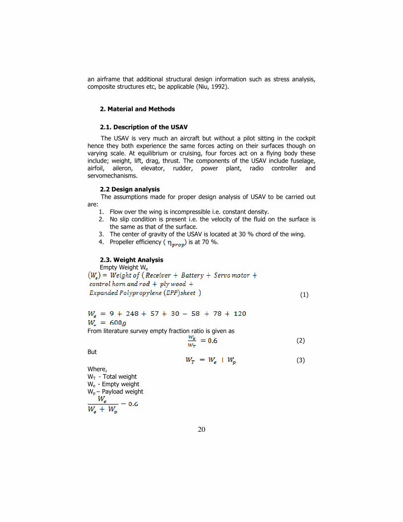
2.3. Weight Analysis Empty Weight We
(1)
From literature survey empty fraction ratio is given as
(2)
But
(3)
Where, WT - Total weight We - Empty weight Wp – Payload weight

21
With
Total take-off weight
2.4. Wing / Lift design analysis
During cruise or level flight Weight and Lift generated by the aircraft are in equilibrium
(4)
Where, WT – Total take-off Weight ρ – Air density V – Cruise Velocity S – Surface area of the wing For an elliptical wing,
(5)
Where, a – Major axis of the ellipse b – Minor axis of the ellipse
By rearranging the wing lift equation the sectional ideal lift coefficient can be calculated as follow
(6)
Where, Vc – Velocity during cruise
Wing ideal lift coefficient
(7)
Ideal Airfoil lift coefficient
(8)
Sectional Maximum lift coefficient
(9)
where, Vs – Stall Velocity
Wing Maximum lift coefficient

22
(10)
Airfoil gross Maximum lift coefficient
(11)
where the wing airfoil “gross” maximum lift coefficient is the airfoil maximum lift coefficient in which the effect of high lift device (e.g. flap) is included.
Aspect Ratio A.R (12)
Where, b – Wing Span (Tip to Tip) c – Mean Aerodynamic Chord (MAC)
Taper ratio (λ) = (13)
Taper ratio (λ) = 0, since the tip chord is Zero for an elliptical wing
2.5. Drag analysis
Fuselage Geometry
Plan Area of fuselage, (14)
Fuselage thickness t = 0.027 Thickness to length (t/l) = 0.05294 Wetted Area i.e. Area exposed to air while flying
(15)
2.6. Fuselage Drag
Mach number, (16)
Where, V – Cruise Velocity γ – Specific heat ratio R – Gas constant T – Temperature of air at sea level

23
Reynold’s Number is given
(17)
Where, Re – Reynold’s number V – Velocity of fluid flow over the fuselage l – Length of the fuselage ν – Kinematic viscosity of air
Boundary layer flow is turbulent
Fuselage coefficient of friction, (18)
From literature survey fuselage finesse ratio
Fuselage Form factor, + 0.0025 FR (19)
Fuselage coefficient of drag, (20)
Fuselage drag force, (21)
2.7. Wing induced drag
Wing coefficient of induced drag, (22)
Wing induced drag force, (23)

24
2.8. Total Drag Force
(24)
2.9. Motor Selection
Power required in overcoming the total drag force
(25)
Hence, a motor rated at five times the power was selected to compensate for
excess drag from high speed flight and also empennage (tail) drag since no analysis were done on them.
2.10. Thrust Analysis
Table 1. Propulsion Summary KV parameter of motor 1100 kV Battery Voltage 11.1 V Propeller Diameter × pitch 6 × 4 Power 240 W
(26)
Converting RPM to rad/sec
Assuming propeller efficiency ( ) is at 70%
Pitch Velocity, (27)
Thrust produced, (28)
2.11. Control Surfaces
There are two main aspects to the design of control surfaces, i.e. their position and size. Varying them will give different degrees of control effectiveness in terms of roll, pitch and yaw.
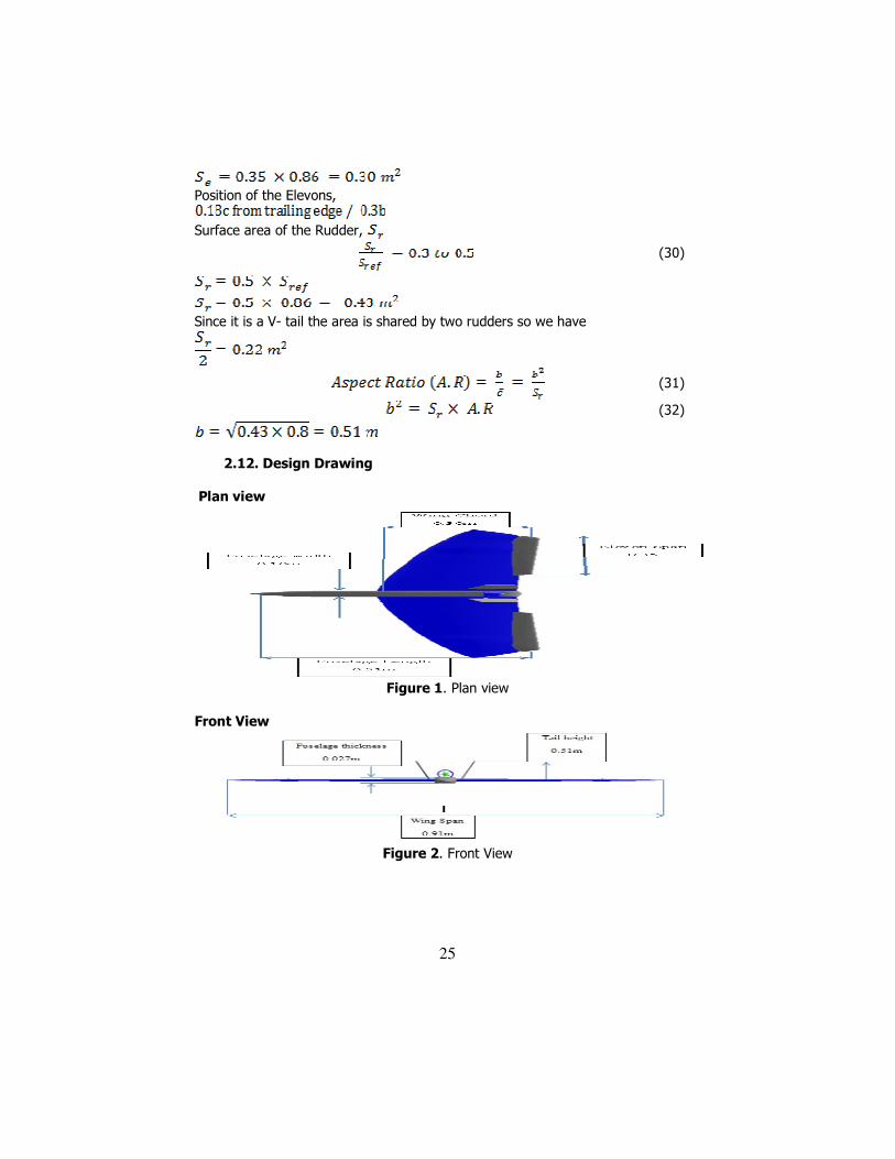
Surface area of the Elevons,
(29)
25
Position of the Elevons,
Surface area of the Rudder,
(30)
Since it is a V- tail the area is shared by two rudders so we have
(31)
(32)
2.12. Design Drawing
Plan view
Figure 1. Plan view
Front View
Figure 2. Front View
26
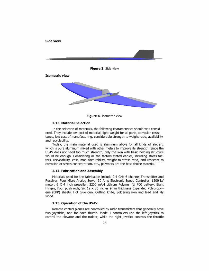
Side view
Figure 3. Side view
Isometric view
Figure 4. Isometric view
2.13. Material Selection
In the selection of materials, the following characteristics should was consid-ered. They include low cost of material, light weight for all parts, corrosion resis-tance, low cost of manufacturing, considerable strength to weight ratio, availability and recyclability.
Today, the main material used is aluminum alloys for all kinds of aircraft, which is pure aluminum mixed with other metals to improve its strength. Since the USAV does not need too much strength, only the skin with basic holding structure would be enough. Considering all the factors stated earlier, including stress fac-tors, recyclability, cost, manufacturability, weight-to-stress ratio, and resistant to corrosion or stress concentration, etc., polymers are the best choice material.
2.14. Fabrication and Assembly
Materials used for the fabrication include 2.4 GHz 6 channel Transmitter and Receiver, Four Micro Analog Servo, 30 Amp Electronic Speed Controller, 1200 kV motor, 6 X 4 inch propeller, 2200 mAH Lithium Polymer (Li PO) battery, Eight Hinges, Four push rods, Six 12 X 36 inches 9mm thickness Expanded Polypropyl-ene (EPP) sheets, Hot glue gun, Cutting knife, Soldering iron and lead and Ply wood.
2.15. Operation of the USAV
Remote control planes are controlled by radio transmitters that generally have two joysticks, one for each thumb. Mode 1 controllers use the left joystick to control the elevator and the rudder, while the right joystick controls the throttle

27
and ailerons. The right stick has springs to return it to the center, while the left stick will only be centered horizontally. This makes it easy to find the throttle control, as this is the stick that does not center itself vertically. Moving the left stick forward will cause the plane to dive, moving the left stick left will turn the plane left, moving the right stick forward will cause the plane to increase speed and moving the right stick left will cause the plane to roll left. The center of gravity of airplane represents the origin of this coordinate system. The axes are called lateral, longitudinal, and vertical which correspond to pitch, roll, and yaw respectively.
3. Results and Discussions
3.1 Airfoil analysis
Analyses of airfoils were done with computational fluid dynamic software known as JavaFoil. JavaFoil has the ability to generate characteristic curves of air-foils based on the design parameter inputted to it. The performance parameters were then deduced from these curves. The design parameter inputted are listed below
1. Design coefficient of lift (Clmax) = 0.22 2. Thickness to chord ratio (t/c) = 0.03 3. Aspect ratio (A.R) = 3 4. Mach number (M) = 0.05
For a cambered plate the following results were obtained;
Figure 5. Airfoil geometry
Figure 5 shows the airfoil geometry for a cambered plate developed by JAVA foil for a thickness to chord ratio (t/c) of 0.03, design coefficient of lift (Clmax) of 0.22. Lift has been defined as the net force developed perpendicular to the relative wind. The aerodynamic force of lift on an airplane results from the generation of a pressure distribution on the wing.
Figure 6. Pressure distribution

28
The typical airflow patterns exemplify the relationship of static pressure and velocity as defined by Bernoulli. Any object placed in an airstream will have air impact or stagnate at some point near the leading edge. The pressure at this point of stagnation will be an absolute static pressure equal to the total pressure of the airstream. As the flow divides and proceeds around the object, the increases in local velocity produced decreases in static pressure. This procedure of flow is best illustrated by the pressure distributions and flow pattern shown in Figure 7.
Figure 7. Flow pattern
3.2. Lift characteristics
Coefficient of lift plot
-0.4
-0.2
0
0.2
0.4
-15 -10 -5 0 5 10 15 20 25
Angle of attack α˚
Coeff
icie
nt
of
lift
Cl
Figure 8. Coefficient of lift plot
This lift force is described by the following equation:
(33)
The lift coefficient used in this equation is the ratio of the lift pressure and dynamic pressure and is a function of the shape of the wing and angle of attack. Plotting the lift coefficient of the aircraft wing plan form versus angle of attack (α˚) produces the graph of Figure 8. Since the effects of speed, density, area, weight, altitude, etc. are eliminated by the coefficient form; an indication of the true lift capability is obtained. Each angle of attack produces a particular lift coefficient since the angle of attack is the controlling factor in the pressure distribution. Lift coefficient increases with angle of attack up to the maximum lift coefficient Clmax and, as angle of attack is increased beyond the maximum lift angle, the airflow is unable to adhere to the upper surface. The airflow then separates from the upper surface and stall occurs.
29
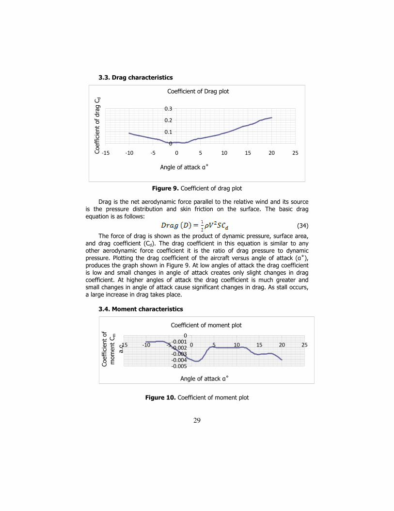
3.3. Drag characteristics
Coefficient of Drag plot
0
0.1
0.2
0.3
-15 -10 -5 0 5 10 15 20 25
Angle of attack α˚
Coeff
icie
nt
of
dra
g C
d
Figure 9. Coefficient of drag plot
Drag is the net aerodynamic force parallel to the relative wind and its source is the pressure distribution and skin friction on the surface. The basic drag equation is as follows:
(34)
The force of drag is shown as the product of dynamic pressure, surface area, and drag coefficient (Cd). The drag coefficient in this equation is similar to any other aerodynamic force coefficient it is the ratio of drag pressure to dynamic pressure. Plotting the drag coefficient of the aircraft versus angle of attack (α˚), produces the graph shown in Figure 9. At low angles of attack the drag coefficient is low and small changes in angle of attack creates only slight changes in drag coefficient. At higher angles of attack the drag coefficient is much greater and small changes in angle of attack cause significant changes in drag. As stall occurs, a large increase in drag takes place.
3.4. Moment characteristics
Coefficient of moment plot
-0.005
-0.004
-0.003
-0.002
-0.001
0
-15 -10 -5 0 5 10 15 20 25
Angle of attack α˚
Coeff
icie
nt
of
mom
ent
Cm
a.c
Figure 10. Coefficient of moment plot

30
The moment about the aerodynamic center has its source in the relative pressure distribution and requires application of the coefficient form of expression for proper evaluation. The moment about the aerodynamic center is expressed by the following equation:
(35)
Where, Ma.c – Moment about the aerodynamic center (a.c) Cm a.c – Coefficient of moment about the aerodynamic center S – Wing area C – Chord
A graph of coefficient of moment about the aerodynamic centre against angle of attack was as shown in Figure 10.The sign convention applied to moment coefficients is that the nose-up moment is positive. Since the plot shows a negative trend the aircraft will tend to nose-down.
3.5. Lift to drag ratio
With the lift and drag data available for the airplane, the proportions of Cl and Cd can be calculated for each specific angle of attack. The resulting plot of lift-drag ratio with angle of attack in Figure 11 shows that L/D increases to some maximum then decreases at the higher lift coefficients and angles of attack. The (L/D)max occurs at one specific angle of attack and lift coefficient. If the airplane is operated in steady flight at (L/D)max the total drag is at a minimum. Any angle of attack lower or higher than that for (L/D)max reduces the lift-drag ratio and consequently increases the total drags for a given aircraft lift.
L/D VS Angle of attack α˚
-20
-10
0
10
20
-15 -10 -5 0 5 10 15 20 25
Angle of attack α˚
Lift
to D
rag R
atio -
L/D
Figure 11. Plot of Lift to drag ratio against Angle of attack
3.6. Aerodynamic center (A.C)
The aerodynamic center is the point on the chord where the coefficients of moment are constant-the point where all changes in lift take place.

31
If the two symmetrical airfoils are subject to an up gust, an increase in lift will take place at the aerodynamic center (A.C). If the center of gravity (C.G) is ahead of the aerodynamic center (A.C), the change in lift creates a nose down moment about the C.G which tends to return the airfoil to the equilibrium angle of attack. This stable, “weather cocking” tendency to return to equilibrium is a very necessary feature in any airplane. If the C.G is aft of the A.C the change in lift due to the up gust takes place at the AC and creates a nose up moment about the C.G. this nose up moment tends to displace the airplane farther from the equilibrium and makes the aircraft unstable. The aircraft is similar to a ball balanced on a peak. Hence, to have a stable aircraft, the C.G must be located ahead of the aircraft A.C.
Since the aerodynamic center (A.C) has a maximum of 50% and a minimum of 20 % chord, the aircraft center of gravity (C.G) has to be placed forward of 20% chord for the aircraft to have longitudinal stability.
4. Conclusion
The USAV is a complex combination of advanced technologies in aerodynamics, structures, materials, stability and system integration. The airfoil geometry and pressure distribution, lift characteristics, drag characeristics, moment characteristics, lift to drag ratio and the aerodynamic centre for the USAV were determined. These parameters are important to the design and workability of the USAV.
References
[1] Ackerman E., Japan Earthquake: Global Hawk UAV May Be Able to Peek Inside Damaged Reactors, Spectrum. IEEE, 17 Mar. 2011.
[2] Etkin B., Reid L.D., Dynamics of Flight, Stability and Control, Third Edi-tion, Wiley, 1996.
[3] Frankenberger J.R., Huang C., Nouwakpo K., Low-Altitude Digital Pho-togrammetry Technique to Assess Ephemeral Gully Erosion, Geoscience and Remote Sensing Symposium, IGARSS 2008. IEEE International, 2008.
[4] Huber M., Evergreen supports UAV team mapping Haitian Relief, Avia-tion International News, 2011.
[5] Ian G.R, The rate of the predator empire: Tracing the History of U.S Drones, understanding empire, 2013. http://understandingempire.word press.com/2-0-G-brief-history-of-US-Drones/.html
[6] Jenkinson L.R., Simpkin P., Rhodes D., Civil Jet Aircraft Design, But-terworth-Heinemann, 2010.
[7] Kruggl K., Quaritsch M., Wischounig-Strucl D., Bhattacharya S., Shah M., Rinner B., Networked UAVs as aerial sensor network for disaster management applications, Elektrotechnik und Informationstechnik 127(3): 56-63, 2010.

32
[8] Lehman R.L., McLaren M. G., Greenhut V. A., Idol J. D., Strange D.J., Kosmatka S.H., Wang W., Ridilla D.R, Buczek M. B, Fische W.F., Mechani-cal Engineering Handbook Ed. Frank Kreith Boca Raton: CRC Press LLC., 1999.
[9] Niu C.Y., Airframe structural design. Conmilit press LTD Hong Kong, 1992.
[10] NOVA,“spies that fly – Timeline of UAVs” http://www.pbs.org/wgbh/nova/spiesfly/UAVs.html,
[11] Pratt K., Hans T., Ludwig C., Requirements for Semi-Autonomous Flight in Miniature UAVs for Structural Inspection, AUVSI's Unmanned Systems North America, Orlando, Florida, Association for Unmanned Ve-hicle Systems International, 2006.
[12] Raymer D.P., Aircraft Design: a conceptual approach, American Insti-tute of Aeronautics and Astronautics Inc., Washington D.C., 2006.
[13] Sadraey M., Aircraft Performance Analysis, VDM Verlag Dr. Müller, 2013.
[14] Suzuki T., Kitamura M., Amano Y., Hashizume T., Real-time hazard map generation using small unmanned aerial vehicle, SICE Annual Con-ference, 2008.
[15] Wikipedia: History of Unmanned Aerial Vehicles http://en.m.wikipedia.org/wiki/History_of_Unmanned_aerial_Vehicle,
[16] Yang Q.C., HaiYan C., YongCan C., Autopilots for Small Unmanned Ae-rial Vehicles: A Survey, International Journal of Control, Automation, and Systems, 8(1) 36-44, 2010.
Addresses:
• Akinnuli B.O., Department of Mechanical Engineering, Federal Univer-sity of Technology, Akure, Ondo State, Nigeria. [email protected]
• Agboola O.O., Department of Mechanical Engineering, Landmark Uni-versity, Omu-Aran, Kwara State, Nigeria, [email protected]
• Ikubanni P.P., Department of Mechanical Engineering, Landmark Uni-versity, Omu-Aran, Kwara State, Nigeria. [email protected]
Related Documents


