International Journal of Recent Technology and Engineering (IJRTE) ISSN: 2277-3878 (Online), Volume-8 Issue-4, November 2019 12428 Published By: Blue Eyes Intelligence Engineering & Sciences Publication Retrieval Number: D8954118419/2019©BEIESP DOI:10.35940/ijrte.D8954.118419 Journal Website: www.ijrte.org Abstract: Silos usually work as storage structures between offer and demand for varied product, and their structural safety has long been of interest to the engineering profession due to seismic effect. This is especially true for dynamically loaded silos, e.g., just in case of seismic excitation. Significantly thin-walled cylindrical silos are extremely susceptible to seismic Iatrogenic pressures which might cause essential buckling phenomena of the silo shell. The analysis of silos may be administered in two, alternative ways. Within the initial, self-Wight, the seismic loading is sculpturesque through statically equivalent loads acting on the shell. As an alternative, a time history analysis could be administered, during which nonlinear phenomena because of the filling as well because the interaction between the shells, and therefore, the granular material is taken under consideration. The paper presents a comparison of an analytical design of steel and concrete comparison. Do all different types of loads which is action on the steel and concrete silo those approaches. The model used for the nonlinear time history analysis considers the granular material by suggests that of thinker granular strain approach for hypoplasticity theory. The interaction effects between the two types of Reaction and the cost comparison of the silos. Keywords :. Concrete silos, Steel Silo, Corrugated Sheet, Vertical Storage System, seismic load, cost. I. INTRODUCTION Silo and therefore, the corresponding structure is analyzed and designed. Silos are the generic name for upright containers used for storing granular materials, and their supports. Containers are the tanks for storing granular materials. The term granular materials are taken to incorporate, “fine particles.” Silo walls are the upright wall of the containers. Hopper is the inclined wall of the containers. The structural materials of the silos are often concrete and steel. Bulk material handling system could be a tedious Manuscript published on November 30, 2019. * Correspondence Author D.S.Vijayan*, is Associate Professor Department of civil Engineering Aarupadai Veedu Institute of Technology, Vinayaka mission research foundation, India PH-+91-9176477171. E-mail: [email protected] S Arviand, Research Scholar Department of civil Engineering Aarupadai Veedu Institute of Technology, Vinayaka mission research foundation, India PH-+91-9940089968. E-mail: [email protected] Mithun P S, Nizam Muhammed, UG student Department of civil Engineering Aarupadai Veedu Institute of Technology, Vinayaka mission research foundation, India Yahiya Yoosuf Thattarth, UG student Department of civil Engineering Aarupadai Veedu Institute of Technology, Vinayaka mission research foundation, India © The Authors. Published by Blue Eyes Intelligence Engineering and Sciences Publication (BEIESP). This is an open access article under the CC-BY-NC-ND license http://creativecommons.org/licenses/by-nc-nd/4.0/ method. Several failures are the results of loading, and therefore, the owner faces the immediate prices of lost conditions not anticipated by the designer. In production and repairs, personnel within the neighborhood we tend to describe style procedures that are exposed to danger, and therefore, the designer has found it to achieve success. The design of silos & their structure involves three vital factors like, bulk material, geometric, and structural issues. Bulk material concerns are vital as a result of the resistance and cohesive properties of bulk solids vary from one solid to a different, and these properties have an effect on material behavior significantly. Additionally, a given bulk solid’s flow properties will vary dramatically with changes in varied parameters, together with particle size, moisture, temperature, and consolidating pressure. This variability of properties makes testing at actual conditions a lot of vital for correct bin and silo style than initially seem. Established style procedures embrace choice of the optimum hopper angles and minimum outlet dimensions. The best discharge mode is one wherever, at a steady state, all material flows while not obstruction. This can be noted as mass flow. The discharge mode wherever just some fabric flows is allowed is termed funnel flow. In the mass flow, the fabric doesn't essentially move at a standardized rate throughout: rate variations across any horizontal crosswise are doable. Fig. 1.Silo supporting structure The structural style of a silo needs, among different things, data of the distribution of pressures and shear stresses on its walls and the way that distribution varies throughout charging, storage at rest, discharging, and recharging. Design and Cost Efficiency of Steel Silos and Concrete Silo D.S.Vijayan, S.Arvindan, Mithun P S, Nizam Muhammed, Yahiya Yoosuf Thattarth

Welcome message from author
This document is posted to help you gain knowledge. Please leave a comment to let me know what you think about it! Share it to your friends and learn new things together.
Transcript
International Journal of Recent Technology and Engineering (IJRTE) ISSN: 2277-3878 (Online), Volume-8 Issue-4, November 2019
12428
Published By: Blue Eyes Intelligence Engineering & Sciences Publication
Retrieval Number: D8954118419/2019©BEIESP DOI:10.35940/ijrte.D8954.118419 Journal Website: www.ijrte.org
Abstract: Silos usually work as storage structures between offer
and demand for varied product, and their structural safety has long been of interest to the engineering profession due to seismic effect. This is especially true for dynamically loaded silos, e.g., just in case of seismic excitation. Significantly thin-walled cylindrical silos are extremely susceptible to seismic Iatrogenic pressures which might cause essential buckling phenomena of the silo shell. The analysis of silos may be administered in two, alternative ways. Within the initial, self-Wight, the seismic loading is sculpturesque through statically equivalent loads acting on the shell. As an alternative, a time history analysis could be administered, during which nonlinear phenomena because of the filling as well because the interaction between the shells, and therefore, the granular material is taken under consideration. The paper presents a comparison of an analytical design of steel and concrete comparison. Do all different types of loads which is action on the steel and concrete silo those approaches. The model used for the nonlinear time history analysis considers the granular material by suggests that of thinker granular strain approach for hypoplasticity theory. The interaction effects between the two types of Reaction and the cost comparison of the silos.
Keywords :. Concrete silos, Steel Silo, Corrugated Sheet, Vertical Storage System, seismic load, cost.
I. INTRODUCTION
Silo and therefore, the corresponding structure is analyzed and designed. Silos are the generic name for upright containers used for storing granular materials, and their supports. Containers are the tanks for storing granular materials. The term granular materials are taken to incorporate, “fine particles.” Silo walls are the upright wall of the containers. Hopper is the inclined wall of the containers. The structural materials of the silos are often concrete and steel. Bulk material handling system could be a tedious Manuscript published on November 30, 2019. * Correspondence Author
D.S.Vijayan*, is Associate Professor Department of civil Engineering Aarupadai Veedu Institute of Technology, Vinayaka mission research foundation, India PH-+91-9176477171. E-mail: [email protected]
S Arviand, Research Scholar Department of civil Engineering Aarupadai Veedu Institute of Technology, Vinayaka mission research foundation, India PH-+91-9940089968. E-mail: [email protected]
Mithun P S, Nizam Muhammed, UG student Department of civil Engineering Aarupadai Veedu Institute of Technology, Vinayaka mission research foundation, India
Yahiya Yoosuf Thattarth, UG student Department of civil Engineering Aarupadai Veedu Institute of Technology, Vinayaka mission research foundation, India © The Authors. Published by Blue Eyes Intelligence Engineering and Sciences Publication (BEIESP). This is an open access article under the CC-BY-NC-ND license http://creativecommons.org/licenses/by-nc-nd/4.0/
method. Several failures are the results of loading, and therefore, the owner faces the immediate prices of lost conditions not anticipated by the designer. In production and repairs, personnel within the neighborhood we tend to describe style procedures that are exposed to danger, and therefore, the designer has found it to achieve success. The design of silos & their structure involves three vital factors like, bulk material, geometric, and structural issues. Bulk material concerns are vital as a result of the resistance and cohesive properties of bulk solids vary from one solid to a different, and these properties have an effect on material behavior significantly. Additionally, a given bulk solid’s flow
properties will vary dramatically with changes in varied parameters, together with particle size, moisture, temperature, and consolidating pressure. This variability of properties makes testing at actual conditions a lot of vital for correct bin and silo style than initially seem.
Established style procedures embrace choice of the optimum hopper angles and minimum outlet dimensions. The best discharge mode is one wherever, at a steady state, all material flows while not obstruction. This can be noted as mass flow. The discharge mode wherever just some fabric flows is allowed is termed funnel flow. In the mass flow, the fabric doesn't essentially move at a standardized rate throughout: rate variations across any horizontal crosswise are doable.
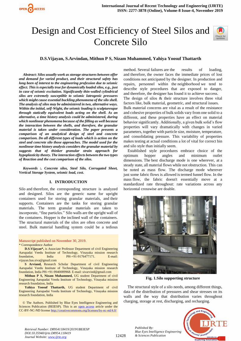
Fig. 1. Silo supporting structure
The structural style of a silo needs, among different things, data of the distribution of pressures and shear stresses on its walls and the way that distribution varies throughout charging, storage at rest, discharging, and recharging.
Design and Cost Efficiency of Steel Silos and Concrete Silo
D.S.Vijayan, S.Arvindan, Mithun P S, Nizam Muhammed, Yahiya Yoosuf Thattarth
Design and Cost Efficiency of Steel Silos and Concrete Silo
12429
Published By: Blue Eyes Intelligence Engineering & Sciences Publication
Retrieval Number: D8954118419/2019©BEIESP DOI:10.35940/ijrte.D8954.118419 Journal Website: www.ijrte.org
II. DATA AND CALCULATION
A. GENERAL
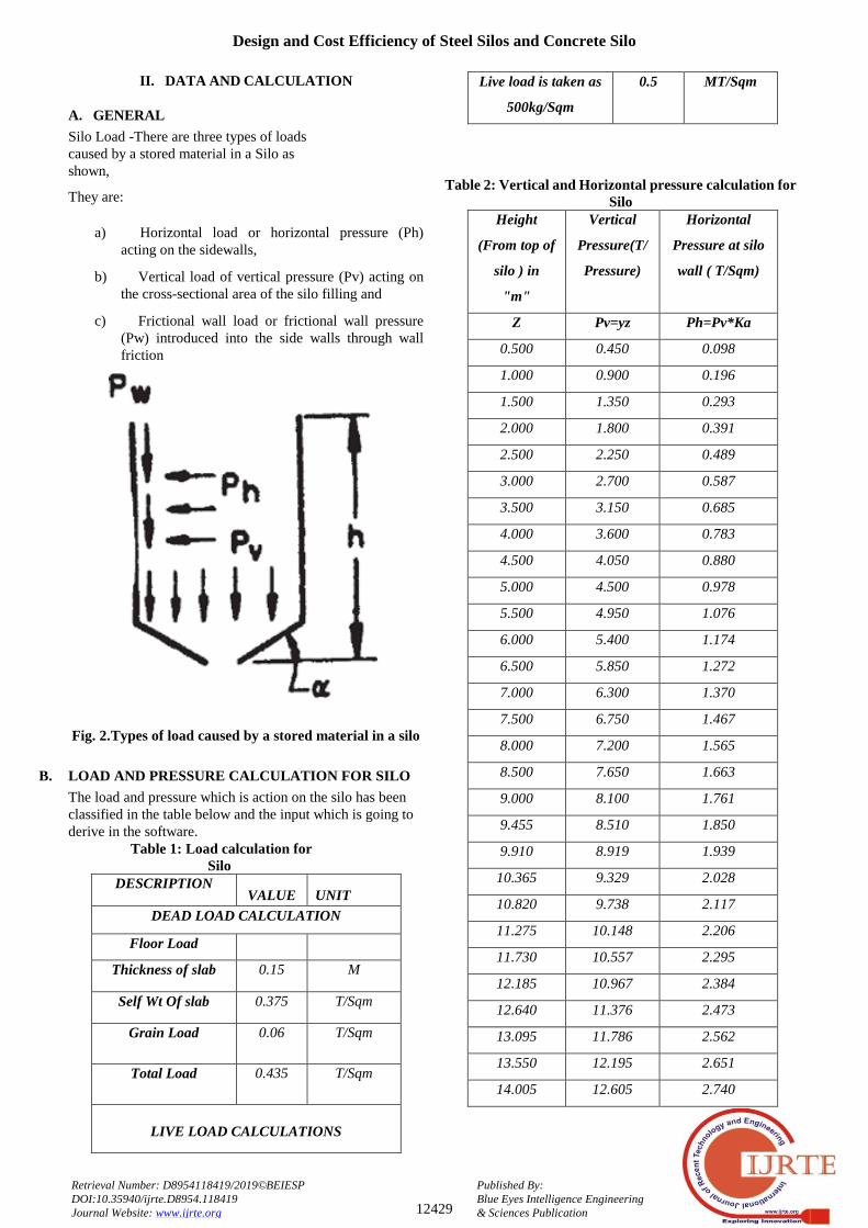
Silo Load -There are three types of loads caused by a stored material in a Silo as shown,
They are:
a) Horizontal load or horizontal pressure (Ph) acting on the sidewalls,
b) Vertical load of vertical pressure (Pv) acting on the cross-sectional area of the silo filling and
c) Frictional wall load or frictional wall pressure (Pw) introduced into the side walls through wall friction
Fig. 2. Types of load caused by a stored material in a silo
B. LOAD AND PRESSURE CALCULATION FOR SILO
The load and pressure which is action on the silo has been classified in the table below and the input which is going to derive in the software.
Table 1: Load calculation for Silo
DESCRIPTION VALUE UNIT
DEAD LOAD CALCULATION
Floor Load
Thickness of slab 0.15 M
Self Wt Of slab 0.375 T/Sqm
Grain Load 0.06 T/Sqm
Total Load 0.435 T/Sqm
LIVE LOAD CALCULATIONS
Live load is taken as
500kg/Sqm
0.5 MT/Sqm
Table 2: Vertical and Horizontal pressure calculation for Silo
Height
(From top of
silo ) in
"m"
Vertical
Pressure(T/
Pressure)
Horizontal
Pressure at silo
wall ( T/Sqm)
Z Pv=yz Ph=Pv*Ka
0.500 0.450 0.098
1.000 0.900 0.196
1.500 1.350 0.293
2.000 1.800 0.391
2.500 2.250 0.489
3.000 2.700 0.587
3.500 3.150 0.685
4.000 3.600 0.783
4.500 4.050 0.880
5.000 4.500 0.978
5.500 4.950 1.076
6.000 5.400 1.174
6.500 5.850 1.272
7.000 6.300 1.370
7.500 6.750 1.467
8.000 7.200 1.565
8.500 7.650 1.663
9.000 8.100 1.761
9.455 8.510 1.850
9.910 8.919 1.939
10.365 9.329 2.028
10.820 9.738 2.117
11.275 10.148 2.206
11.730 10.557 2.295
12.185 10.967 2.384
12.640 11.376 2.473
13.095 11.786 2.562
13.550 12.195 2.651
14.005 12.605 2.740
International Journal of Recent Technology and Engineering (IJRTE) ISSN: 2277-3878 (Online), Volume-8 Issue-4, November 2019
12430
Published By: Blue Eyes Intelligence Engineering & Sciences Publication
Retrieval Number: D8954118419/2019©BEIESP DOI:10.35940/ijrte.D8954.118419 Journal Website: www.ijrte.org
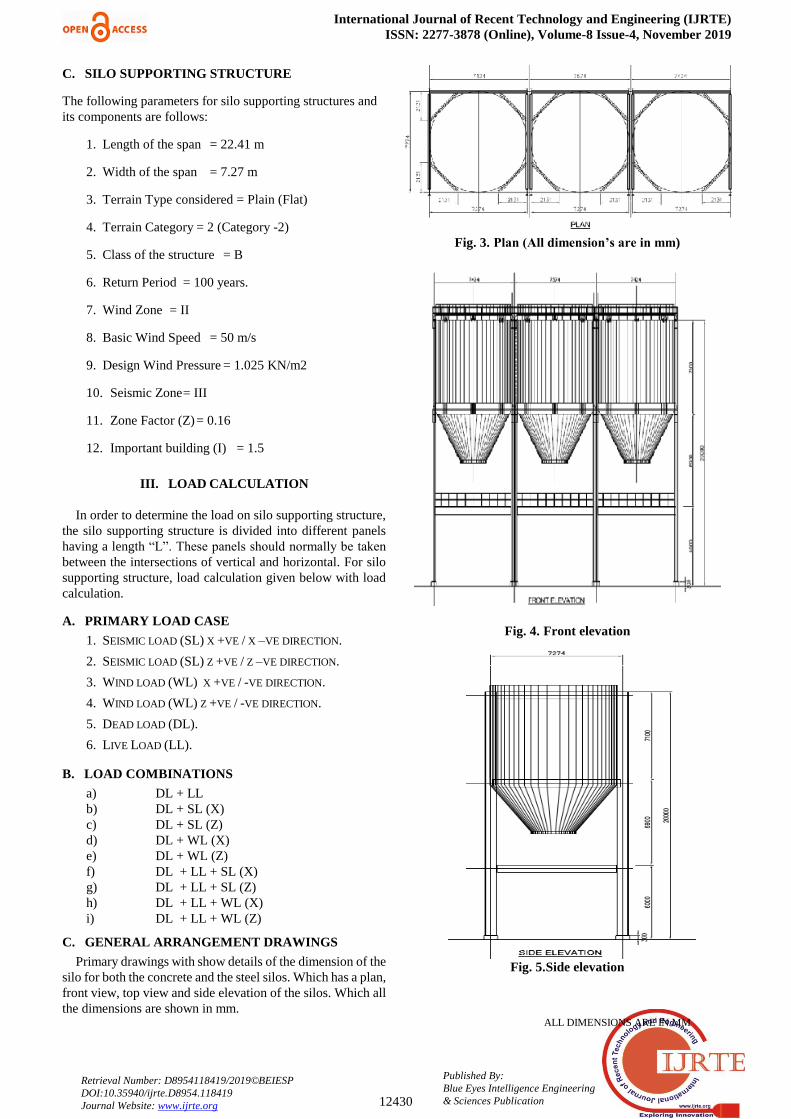
C. SILO SUPPORTING STRUCTURE
The following parameters for silo supporting structures and its components are follows:
1. Length of the span = 22.41 m
2. Width of the span = 7.27 m
3. Terrain Type considered = Plain (Flat)
4. Terrain Category = 2 (Category -2)
5. Class of the structure = B
6. Return Period = 100 years.
7. Wind Zone = II
8. Basic Wind Speed = 50 m/s
9. Design Wind Pressure = 1.025 KN/m2
10. Seismic Zone = III
11. Zone Factor (Z) = 0.16
12. Important building (I) = 1.5
III. LOAD CALCULATION
In order to determine the load on silo supporting structure, the silo supporting structure is divided into different panels having a length “L”. These panels should normally be taken
between the intersections of vertical and horizontal. For silo supporting structure, load calculation given below with load calculation.
A. PRIMARY LOAD CASE
1. SEISMIC LOAD (SL) X +VE / X –VE DIRECTION.
2. SEISMIC LOAD (SL) Z +VE / Z –VE DIRECTION.
3. WIND LOAD (WL) X +VE / -VE DIRECTION.
4. WIND LOAD (WL) Z +VE / -VE DIRECTION.
5. DEAD LOAD (DL).
6. LIVE LOAD (LL).
B. LOAD COMBINATIONS
a) DL + LL b) DL + SL (X) c) DL + SL (Z) d) DL + WL (X) e) DL + WL (Z) f) DL + LL + SL (X) g) DL + LL + SL (Z) h) DL + LL + WL (X) i) DL + LL + WL (Z)
C. GENERAL ARRANGEMENT DRAWINGS
Primary drawings with show details of the dimension of the silo for both the concrete and the steel silos. Which has a plan, front view, top view and side elevation of the silos. Which all the dimensions are shown in mm. ALL DIMENSIONS ARE IN MM
Fig. 3. Plan (All dimension’s are in mm)
Fig. 4. Front elevation
Fig. 5. Side elevation
Design and Cost Efficiency of Steel Silos and Concrete Silo
12431
Published By: Blue Eyes Intelligence Engineering & Sciences Publication
Retrieval Number: D8954118419/2019©BEIESP DOI:10.35940/ijrte.D8954.118419 Journal Website: www.ijrte.org
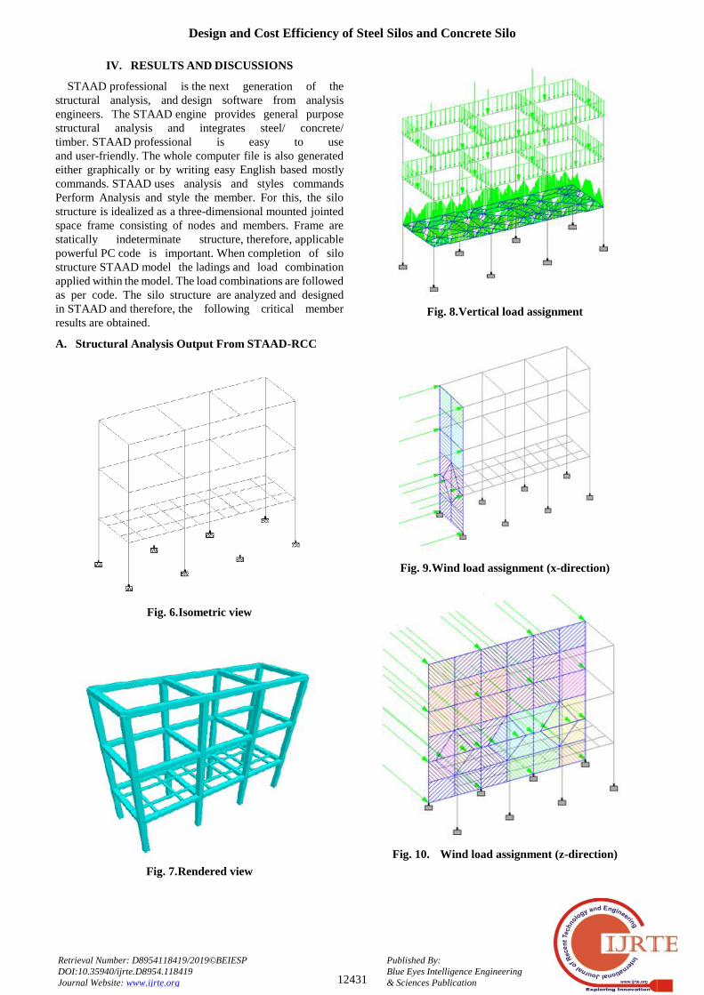
IV. RESULTS AND DISCUSSIONS
STAAD professional is the next generation of the structural analysis, and design software from analysis engineers. The STAAD engine provides general purpose structural analysis and integrates steel/ concrete/ timber. STAAD professional is easy to use and user-friendly. The whole computer file is also generated either graphically or by writing easy English based mostly commands. STAAD uses analysis and styles commands Perform Analysis and style the member. For this, the silo structure is idealized as a three-dimensional mounted jointed space frame consisting of nodes and members. Frame are statically indeterminate structure, therefore, applicable powerful PC code is important. When completion of silo structure STAAD model the ladings and load combination applied within the model. The load combinations are followed as per code. The silo structure are analyzed and designed in STAAD and therefore, the following critical member results are obtained.
A. Structural Analysis Output From STAAD-RCC
Fig. 6. Isometric view
Fig. 7. Rendered view
Fig. 8. Vertical load assignment
Fig. 9. Wind load assignment (x-direction)
Fig. 10. Wind load assignment (z-direction)
International Journal of Recent Technology and Engineering (IJRTE) ISSN: 2277-3878 (Online), Volume-8 Issue-4, November 2019
12432
Published By: Blue Eyes Intelligence Engineering & Sciences Publication
Retrieval Number: D8954118419/2019©BEIESP DOI:10.35940/ijrte.D8954.118419 Journal Website: www.ijrte.org
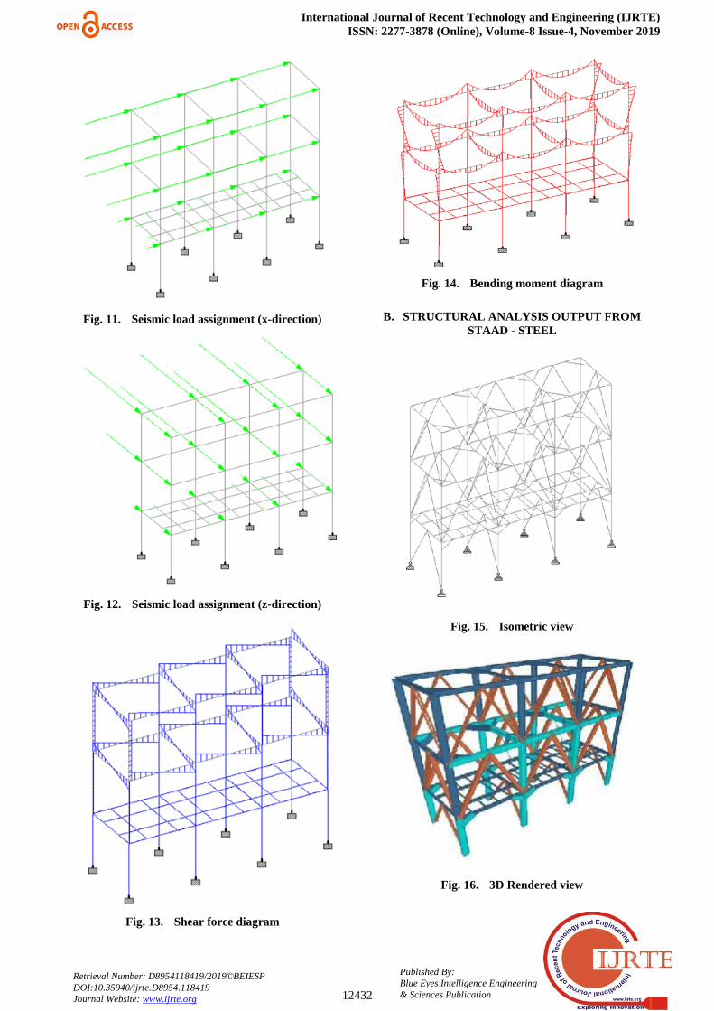
Fig. 11. Seismic load assignment (x-direction)
Fig. 12. Seismic load assignment (z-direction)
Fig. 13. Shear force diagram
Fig. 14. Bending moment diagram
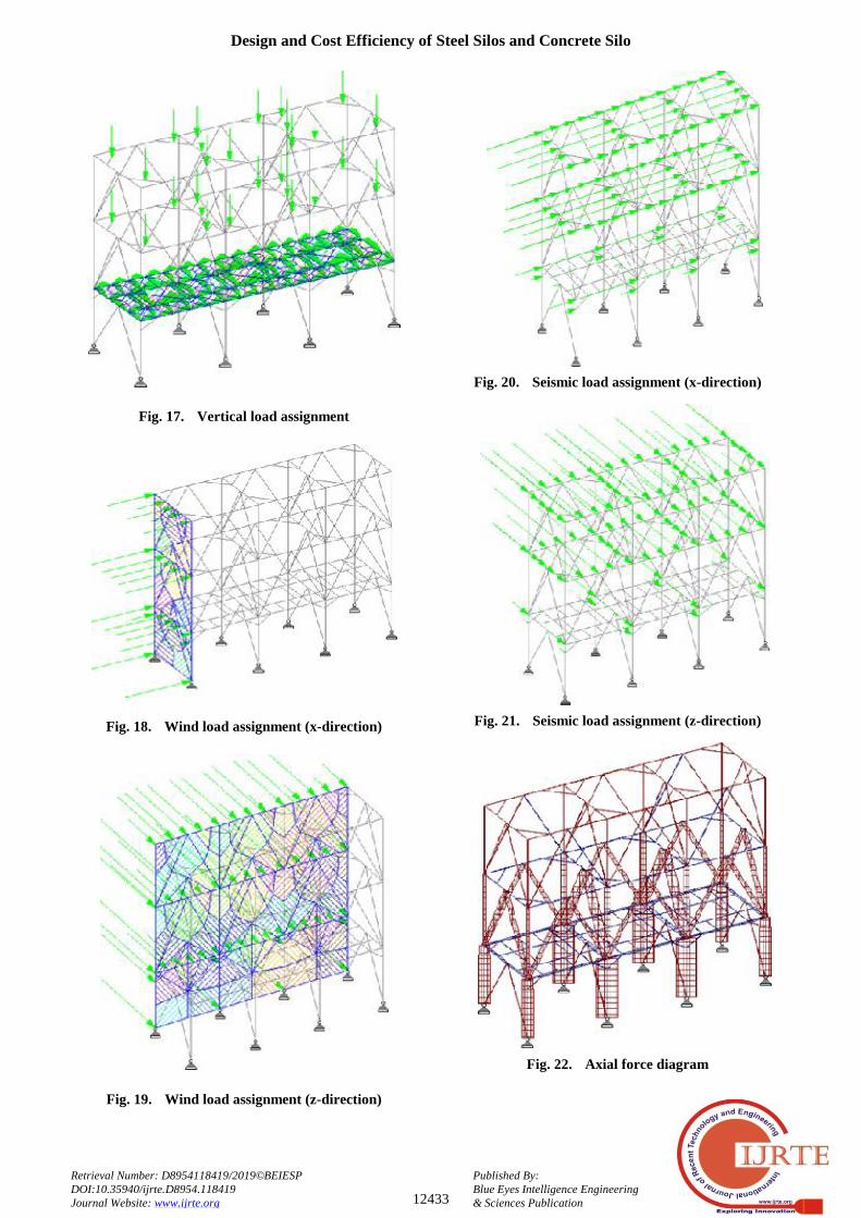
B. STRUCTURAL ANALYSIS OUTPUT FROM STAAD - STEEL
Fig. 15. Isometric view
Fig. 16. 3D Rendered view
Design and Cost Efficiency of Steel Silos and Concrete Silo
12433
Published By: Blue Eyes Intelligence Engineering & Sciences Publication
Retrieval Number: D8954118419/2019©BEIESP DOI:10.35940/ijrte.D8954.118419 Journal Website: www.ijrte.org
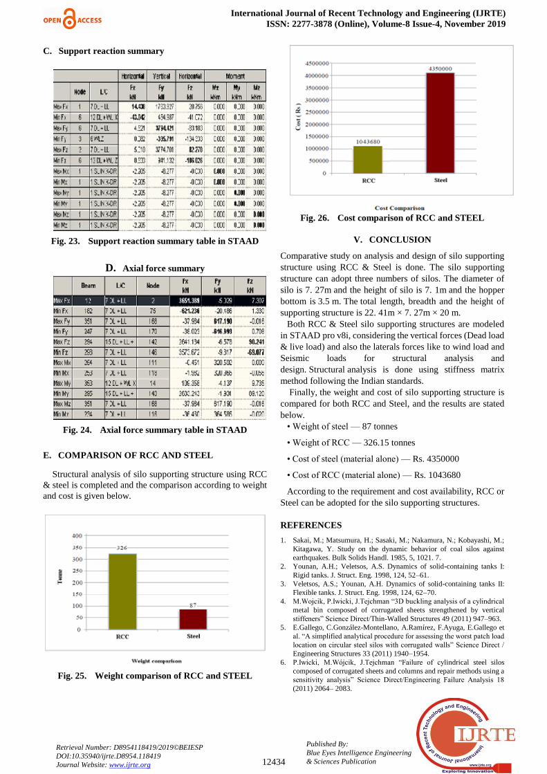
Fig. 17. Vertical load assignment
Fig. 18. Wind load assignment (x-direction)
Fig. 19. Wind load assignment (z-direction)
Fig. 20. Seismic load assignment (x-direction)
Fig. 21. Seismic load assignment (z-direction)
Fig. 22. Axial force diagram
International Journal of Recent Technology and Engineering (IJRTE) ISSN: 2277-3878 (Online), Volume-8 Issue-4, November 2019
12434
Published By: Blue Eyes Intelligence Engineering & Sciences Publication
Retrieval Number: D8954118419/2019©BEIESP DOI:10.35940/ijrte.D8954.118419 Journal Website: www.ijrte.org
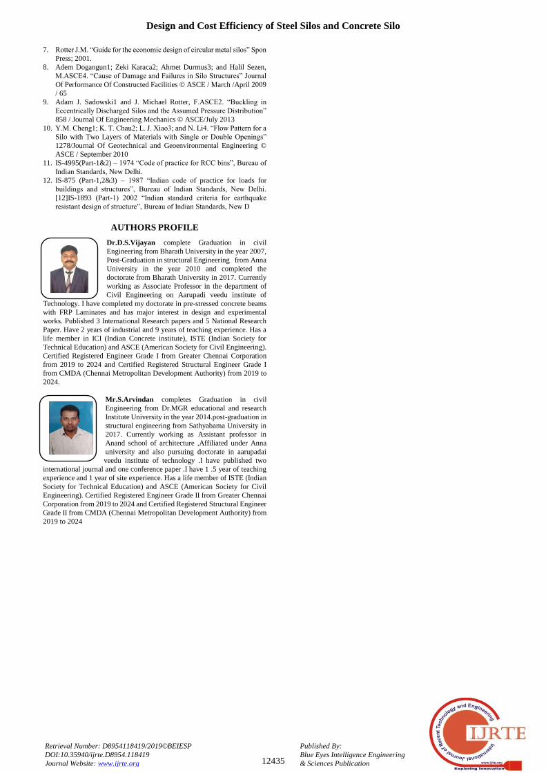
C. Support reaction summary
Fig. 23. Support reaction summary table in STAAD
D. Axial force summary
Fig. 24. Axial force summary table in STAAD
E. COMPARISON OF RCC AND STEEL
Structural analysis of silo supporting structure using RCC & steel is completed and the comparison according to weight and cost is given below.
Fig. 25. Weight comparison of RCC and STEEL
Fig. 26. Cost comparison of RCC and STEEL
V. CONCLUSION
Comparative study on analysis and design of silo supporting structure using RCC & Steel is done. The silo supporting structure can adopt three numbers of silos. The diameter of silo is 7. 27m and the height of silo is 7. 1m and the hopper bottom is 3.5 m. The total length, breadth and the height of supporting structure is 22. 41m × 7. 27m × 20 m.
Both RCC & Steel silo supporting structures are modeled in STAAD pro v8i, considering the vertical forces (Dead load & live load) and also the laterals forces like to wind load and Seismic loads for structural analysis and design. Structural analysis is done using stiffness matrix method following the Indian standards.
Finally, the weight and cost of silo supporting structure is compared for both RCC and Steel, and the results are stated below.
• Weight of steel — 87 tonnes
• Weight of RCC — 326.15 tonnes
• Cost of steel (material alone) — Rs. 4350000
• Cost of RCC (material alone) — Rs. 1043680
According to the requirement and cost availability, RCC or Steel can be adopted for the silo supporting structures.
REFERENCES
1. Sakai, M.; Matsumura, H.; Sasaki, M.; Nakamura, N.; Kobayashi, M.; Kitagawa, Y. Study on the dynamic behavior of coal silos against earthquakes. Bulk Solids Handl. 1985, 5, 1021. 7.
2. Younan, A.H.; Veletsos, A.S. Dynamics of solid-containing tanks I: Rigid tanks. J. Struct. Eng. 1998, 124, 52–61.
3. Veletsos, A.S.; Younan, A.H. Dynamics of solid-containing tanks II: Flexible tanks. J. Struct. Eng. 1998, 124, 62–70.
4. M.Wojcik, P.Iwicki, J.Tejchman “3D buckling analysis of a cylindrical
metal bin composed of corrugated sheets strengthened by vertical stiffeners” Science Direct/Thin-Walled Structures 49 (2011) 947–963.
5. E.Gallego, C.González-Montellano, A.Ramírez, F.Ayuga, E.Gallego et al. “A simplified analytical procedure for assessing the worst patch load
location on circular steel silos with corrugated walls” Science Direct /
Engineering Structures 33 (2011) 1940–1954. 6. P.Iwicki, M.Wójcik, J.Tejchman “Failure of cylindrical steel silos
composed of corrugated sheets and columns and repair methods using a sensitivity analysis” Science Direct/Engineering Failure Analysis 18
(2011) 2064– 2083.
Design and Cost Efficiency of Steel Silos and Concrete Silo
12435
Published By: Blue Eyes Intelligence Engineering & Sciences Publication
Retrieval Number: D8954118419/2019©BEIESP DOI:10.35940/ijrte.D8954.118419 Journal Website: www.ijrte.org
7. Rotter J.M. “Guide for the economic design of circular metal silos” Spon
Press; 2001. 8. Adem Dogangun1; Zeki Karaca2; Ahmet Durmus3; and Halil Sezen,
M.ASCE4. “Cause of Damage and Failures in Silo Structures” Journal
Of Performance Of Constructed Facilities © ASCE / March /April 2009 / 65
9. Adam J. Sadowski1 and J. Michael Rotter, F.ASCE2. “Buckling in
Eccentrically Discharged Silos and the Assumed Pressure Distribution”
858 / Journal Of Engineering Mechanics © ASCE/July 2013 10. Y.M. Cheng1; K. T. Chau2; L. J. Xiao3; and N. Li4. “Flow Pattern for a
Silo with Two Layers of Materials with Single or Double Openings”
1278/Journal Of Geotechnical and Geoenvironmental Engineering © ASCE / September 2010
11. IS-4995(Part-1&2) – 1974 “Code of practice for RCC bins”, Bureau of
Indian Standards, New Delhi. 12. IS-875 (Part-1,2&3) – 1987 “Indian code of practice for loads for
buildings and structures”, Bureau of Indian Standards, New Delhi.
[12]IS-1893 (Part-1) 2002 “Indian standard criteria for earthquake
resistant design of structure”, Bureau of Indian Standards, New D
AUTHORS PROFILE
Dr.D.S.Vijayan complete Graduation in civil Engineering from Bharath University in the year 2007, Post-Graduation in structural Engineering from Anna University in the year 2010 and completed the doctorate from Bharath University in 2017. Currently working as Associate Professor in the department of Civil Engineering on Aarupadi veedu institute of
Technology. I have completed my doctorate in pre-stressed concrete beams with FRP Laminates and has major interest in design and experimental works. Published 3 International Research papers and 5 National Research Paper. Have 2 years of industrial and 9 years of teaching experience. Has a life member in ICI (Indian Concrete institute), ISTE (Indian Society for Technical Education) and ASCE (American Society for Civil Engineering). Certified Registered Engineer Grade I from Greater Chennai Corporation from 2019 to 2024 and Certified Registered Structural Engineer Grade I from CMDA (Chennai Metropolitan Development Authority) from 2019 to 2024.
Mr.S.Arvindan completes Graduation in civil Engineering from Dr.MGR educational and research Institute University in the year 2014.post-graduation in structural engineering from Sathyabama University in 2017. Currently working as Assistant professor in Anand school of architecture ,Affiliated under Anna university and also pursuing doctorate in aarupadai veedu institute of technology .I have published two
international journal and one conference paper .I have 1 .5 year of teaching experience and 1 year of site experience. Has a life member of ISTE (Indian Society for Technical Education) and ASCE (American Society for Civil Engineering). Certified Registered Engineer Grade II from Greater Chennai Corporation from 2019 to 2024 and Certified Registered Structural Engineer Grade II from CMDA (Chennai Metropolitan Development Authority) from 2019 to 2024
Related Documents