Design and Correction of optical Systems Part 7: Geometrical aberrations Summer term 2012 Herbert Gross 1

Welcome message from author
This document is posted to help you gain knowledge. Please leave a comment to let me know what you think about it! Share it to your friends and learn new things together.
Transcript

Design and Correction of optical Systems
Part 7: Geometrical aberrations
Summer term 2012
Herbert Gross
1

Overview
1. Basics 2012-04-18
2. Materials 2012-04-25
3. Components 2012-05-02
4. Paraxial optics 2012-05-09
5. Properties of optical systems 2012-05-16
6. Photometry 2012-05-23
7. Geometrical aberrations 2012-05-30
8. Wave optical aberrations 2012-06-06
9. Fourier optical image formation 2012-06-13
10. Performance criteria 1 2012-06-20
11. Performance criteria 2 2012-06-27
12. Measurement of system quality 2012-07-04
13. Correction of aberrations 1 2012-07-11
14. Optical system classification 2012-07-18
2012-04-18
2

7.1 Representations
7.2 Power expansion of aberrations
7.3 Seidel aberrations
7.4 Surface contributions
7.5 Primary monochromatic aberrations
7.6 Chromatical aberrations
Part 7: Contents
3
2012-05-30

Optical Image Formation
� Perfect optical image:
All rays coming from one object point intersect in one image point
� Real system with aberrations:
1. transverse aberrations in the image plane
2. longitudinal aberrations from the image plane
3. wave aberrations in the exit pupil
4

� Longitudinal aberrations ∆s
� Transverse aberrations ∆y
Representation of Geometrical Aberrations
Gaussian imageplane
ray
longitudinalaberration
∆ s'
optical axis
system
U'reference
point
referenceplane
reference ray
(real or ideal chief ray)
transverse
aberration∆∆∆∆y'
optical axis
system
ray
U'
Gaussianimageplane
reference ray
longitudinal aberrationprojected on the axis
∆∆∆∆l'
optical axis
system
ray
∆∆∆∆l'o
logitudinal aberrationalong the reference ray
5

Representation of Geometrical Aberrations
ideal reference ray angular aberration∆∆∆∆U'
optical axis
system
real ray
x
z
s' < 0∆∆∆∆
W > 0
reference sphere
paraxial ray
real ray
wavefront
R
C
y'∆∆∆∆
Gaussianreference
plane
U'
� Angle aberrations ∆u
� Wave aberrations ∆W
6

Transverse Aberrations
� Typical low order polynomial contributions for:
Defocus, coma, spherical, lateral color
� This allows a quick classification of real curves
linear:
defocus
quadratic:
coma
cubic:
spherical
offset:
lateral color
7

Transverse Aberrations
∆∆∆∆y ∆∆∆∆x
xp
yp
1
-1
1-1
5 µµµµm5 µµµµm
λλλλ= 486 nm
λλλλ= 588 nm
λλλλ= 656 nm
Dy
Dx
tangential sagittal
� Classical aberration curves
� Strong relation to spot diagram
� Usually only linear sampling along the x-, y-axis
no information in the quadrant of the aperture
8

Spot Diagram
� All rays start in one point in the object plane
� The entrance pupil is sampled equidistant
� In the exit pupil, the transferred grid
may be distorted
� In the image plane a spreaded spot
diagram is generated
9

Spot Diagram
� Table with various values of:
1. Field size
2. Color
� Small circle:
Airy diameter for
comparison
� Large circle:
Gaussian moment
486 nm 546 nm 656 nm
axis
fieldzone
fullfield
10

Aberrations of a Single Lens
� Single plane-convex lens,
BK7, f = 100 mm, λ = 500 nm
� Spot as a function of
field position
� Coma shape rotates according
to circular symmetry
� Decrease of performance with
the distance to the axis
x
y
11

Polynomial Expansion of the Aberrations
� Paraxial optics: small field and aperture angles
Aberrations occur for larger angle values
� Two-dimensional Taylor expansion shows field
and aperture dependence
� Expansion for one meridional field point y
� Pupil: cartesian or polar grid in xp / yp
field
point
opticalaxis
axispoint
entrance
pupil
coma rays
outer rays of aperture cone
chief
ray
objectheight y
xp
O
xp
yp
r
θθθθ
yp
ray
objectplane
meridionalplane
sagittalplane
12

∑ ⋅⋅⋅=∆mlk
ml
p
k
klmp ryaryy,,
cos'),,'( θθ
isum number of terms
Type of aberration
2 2 image location
4 5 primary aberrations, 3rd/4th order
6 9 secondary aberrations, 5th/6th order
8 14 higher order
Polynomial Expansion of Aberrations
� Taylor expansion of the deviation:
y' Image height index k
rp Pupil height index l
θ Pupil azimuth angle index m
� Symmetry invariance: selection of special combinations of exponent terms
� Number of terms: sum of
indices in the exponent isum
� The order of the aperture function
depends on the aberration type used:
primary aberrations:
- 3rd order in transverse aberration ∆y
- 4th order in wave aberration W
Since the coupling relation
changes the order by 1
px
W
Ry
∂
∂⋅−=∆
1
13

Power Series Expansion of Aberrations
� General case : two coordinates in object plane and pupil
� Rotational symmetry: 3 invariants
1. Scalar product of field vector and pupil vector
2. Square of field height
3. Square of pupil height
� Therefore:
Only special power
combinations are
physically meaningful
Object
Pupilx
y
P
F
y
x
xp
yp
z
xp
yp
F
P
222 yxFFF +==⋅rr
222
pp yxPPP +==⋅rr
yyxxFPFP pp ⋅+⋅=−⋅⋅=⋅ )cos(PF
ϕϕrr
14

Polynomial Expansion of Aberrations
� Representation of 2-dimensional Taylor series vs field y and aperture r
� Selection rules: checkerboard filling of the matrix
� Constant sum of exponents according to the order
Field y
Spherical
y0 y 1 y 2 y3 y 4 y 5
Distortion r 0y y3
primary
y 5
secondary
r 1r 1
Defocus
Aper-
ture
r r 2r2yComa
primary
r 3r 3
Spherical
primary
r4
r 5r 5
Spherical
secondary
DistortionDistortionTilt
Coma Astigmatism
Image
location
Primary
aberrations /
Seidel
Astig./Curvat.
cos
cos
cos2
cos
Secondary
aberrations
cos
r 3y 2cos2
Coma
secondary
r 4y cos
r 2y3cos
3
r2y3
cos
r1y 4
r1y 4
cos2
r 3y 2
r 12yr 12y
15

Primary Aberrations
Dy
PryAry
CryrSry
⋅+
⋅⋅+⋅⋅⋅+
⋅⋅⋅⋅+⋅=∆
3
222
223
cos
cos
θ
θ
� Expansion of the transverse aberration ∆y on image height y and pupil height r
� Lowest order 3 of real aberrations: primary or Seidel aberrations
� Spherical aberration: S
- no dependence on field, valid on axis
- depends in 3rd order on apertur
� Coma: C
- linear function of field y
- depends in 2rd order on apertur with azimuthal variation
� Astigmatism: A
- linear function of apertur with azimuthal variation
- quadratic function of field size
� Image curvature (Petzval): P
- linear dependence on apertur
- quadratic function of field size
� Distortion: D
- No dependence on apertur
- depends in 3rd order on the field size
16

Transverse Aberrations of Seidel
� Transverse deviations
� Sum of surface
contributions
( ) ( ) ( )[ ]
( ) ( )
( )'
''2
'''''
'''2
''''''
''
'''''''
'''2
''''''''''2'
''2
'''''
3
322
3
2222
3
22
3
322
3
422
DRn
ssyxy
PRn
ssyxyA
Rn
ssyyxxy
CRn
ssyxyyyxxyS
Rn
syxyy
p
p
p
pppp
p
ppp
p
pppppp
p
ppp
+−
++
++
+++−
+=∆
( ) ( ) ( )[ ]
( ) ( )
( )'
''2
'''''
'''2
''''''
''
'''''''
'''2
''''''''''2'
''2
'''''
3
322
3
2222
3
22
3
322
3
422
DRn
ssyxx
PRn
ssyxxA
Rn
ssyyxxx
CRn
ssyxxyyxxxS
Rn
syxxx
p
p
p
pppp
p
ppp
p
pppppp
p
ppp
+−
++
++
+++−
+=∆
∑=
=k
j
jSS1
'
∑=
=k
j
jCC1
'
∑=
=k
j
jAA1
'
∑=
=k
j
jPP1
'
∑=
=k
j
jDD1
'
17

Surface Contributions
� Spherical aberration
� Coma
� Astigmatisms
� Field curvature
� Distortion
−=
jjjj
jjjsnsn
QS1
''
124ω
−⋅⋅
−=
11
124 111
''
1
pjj
pjpj
jjjj
jjjssQ
Qn
snsnQC
ω
ωω
18
2
11
2
124 111
''
1
−⋅
⋅
−=
pjj
pjpj
jjjj
jjjssQ
Qn
snsnQA
ω
ωω
−⋅−
−⋅
⋅
−=
jjrpjj
pjpj
jjjj
jjjnnrssQ
Qn
snsnQP
1
'
11111
''
12
11
2
124
ω
ωω
−⋅
−⋅−
−⋅
⋅
−=
11
1
2
11
2
124 111
'
11111
''
1
pjj
pjpj
jjrpjj
pjpj
jjjj
jjjssQ
Qn
nnrssQ
Qn
snsnQD
ω
ω
ω
ωω

Surface Contributions of Chromatical Aberrations
� Axial chromatical aberration
� Transverse chromatical aberration
� Total chromatical errors
of a system
Hs s
s sQ
n
nj
CHV p
p
j pj pj F
j
j j
=⋅
−⋅
−
1 1
1 1
1ω ω
ν∆
∆ y y HCHV n j
CHV
j
n
' '= ⋅=
∑1
∆ ss
nK
h
fCHL
n
n n
Linse
CHL'
'
' '= − ⋅ = −
⋅
2
2
2
ω ν
j
j
j
CHL
jKν
ωΦ
= 2)(
19

Surface Contributions
� Abbreviations:
1. height ratio of marginal rays
2. height ratio of chief rays
3. Surface invariant of Abbe
4. Abbe invariant of the pupil imaging
ω j
jh
h=
1
ω pj
pj
p
h
h=
1
Q nr s
j j
j j
= ⋅ −
1 1
Q nr s
pj j
j pj
= ⋅ −
1 1
20

Surface Contributions of Seidel
� In 3rd order (Seidel) :
Additive contributions of all surfaces of a system to the total aberration
� Spherical aberration
� Coma
� Astigmatisms
� Field curvature
� Distortion
SRs
psRC ⋅
−
+−⋅=
'
''4
SRs
psRA ⋅
−
+−⋅=
2
'
''4
21
42
2'
'
'
''
'
11
8
)'('
+−⋅
−⋅
−−=
p
s
s
nn
R
n
sRn
nnnS
2
2
'4
)'('
'
''2
nRp
nnnS
Rs
psRP
−−⋅
−
+−⋅=
Rs
psR
nRp
nnnS
Rs
psRE
−
+−⋅
−−⋅
−
+−⋅=
'
''
'2
)'('
'
''4
2
3

Surface Contributions: Example
22
� Seidel aberrations:
representation as sum of
surface contributions possible
� Gives information on correction
of a system
� Example: photographic lens
12
3 45
6 8 9
10
7
Retrofocus F/2.8
Field: w=37°
SI
Spherical Aberration
SII
Coma
-200
0
200
-1000
0
1000
-2000
0
2000
-1000
0
1000
-100
0
150
-400
0
600
-6000
0
6000
SIII
Astigmatism
SIV
Petzval field curvature
SV
Distortion
CI
Axial color
CII
Lateral color
Surface 1 2 3 4 5 6 7 8 9 10 Sum

Lens Contributions of Seidel
� In 3rd order (Seidel) :
Additive contributions of lenses to the total aberration value
(stop at lens position)
� Spherical aberration
� Coma
� Astigmatisms
� Field curvature
� Distortion 0=lensD
+−
−
+⋅= MnX
n
n
fnsClens )12(
1
1
'4
12
2'2
1
sfAlens
⋅−=
2'4
1
snf
nPlens
⋅
+−=
23
⋅
+
−−
⋅
+
−−⋅
−
++
−−= 2
22
23
32
)1(
2
)1(2
1
2
1)1(32
1M
n
nnM
n
nX
n
n
n
n
fnnSlens

Spherical Aberration
� Spherical aberration:
On axis, circular symmetry
� Perfect focussing near axis: paraxial focus
� Real marginal rays: shorter intersection length (for single positive lens)
� Optimal image plane: circle of least rms value
paraxial
focus
marginal
ray focusplane of the
smallest
rms-value
medium
imageplane
As
plane of the
smallest
waist
2 A s
24

Spherical Aberration
� Single positive lens
� Paraxial focal plane near axis,
Largest intersection length
� Shorter intersection length for
rim ray and outer aperture zones
25

� Spherical aberration and focal spot diameter
as a function of the lens bending (for n=1.5)
� Optimal bending for incidence averaged
incidence angles
� Minimum larger than zero:
usually no complete correction possible
Spherical Aberration: Lens Bending
objectplane
imageplane
principalplane
26

Aplanatic Surfaces
� Aplanatic surfaces: zero spherical aberration:
1. Ray through vertex
2. concentric
3. Aplanatic
� Condition for aplanatic
surface:
� Virtual image location
� Applications:
1. Microscopic objective lens
2. Interferometer objective lens
s s und u u' '= =
s s' = = 0
ns n s= ' '
rns
n n
n s
n n
ss
s s=
+=
+=
+'
' '
'
'
'
27

� Aplanatic lenses
� Combination of one concentric and
one aplanatic surface:
zero contribution of the whole lens to
spherical aberration
� Not useful:
1. aplanatic-aplanatic
2. concentric-concentric
bended plane parallel plate,
nearly vanishing effect on rays
Aplanatic Lenses
A-A : parallel offset
A-C :
convergence enhanced
C-C :no effect
C-A :convergence reduced
28

� Reason for astigmatism:
chief ray passes a surface under an oblique angle,
the refractive power in tangential and sagittal section are different
� A tangential and a sagittal focal line is found in different
distances
� Tangential rays meets closer to the surface
� In the midpoint between both focal lines:
circle of least confusion
Astigmatism
29

� Beam cross section in the case of astigmatism:
- Elliptical shape transforms its aspect ratio
- degenerate into focal lines in the focal plane distances
- special case of a circle in the midpoint: smallest spot
y
x
z
tangentialfocus
sagittalfocuscircle of least
confusion
tangentialaperture
sagittalaperture
Astigmatism
30

Imaging of a polar grid in different planes
sagittal line
tangential line
entrance
pupil
exit
pupil
object
circlesagittal
focus
tangential
focus
best focus
image space
Astigmatism
31

Field Curvature and Image Shells
� Imaging with astigmatism:
Tangential and sagittal image shell depending on the azimuth
� Difference between the image shells: astigmatism
� Astigmatism corrected:
It remains a curved image shell,
Bended field: also called Petzval curvature
� System with astigmatism:
Petzval sphere is not an optimal
surface with good imaging resolution
� Law of Petzval: curvature given by:
� No effect of bending on curvature,
important: distribution of lens
powers and indices
1 1
rn
n fp k kk
= − ⋅⋅
∑'
32

Astigmatisms and Curvature of Field
∆∆ ∆
ss s
best
sag'
' 'tan
=+
2
( )∆ ∆ ∆ ∆s s s spet sag pet' ' ' 'tan − = ⋅ −3
∆ ∆ ∆s s sast sag' ' 'tan
= −
� Image surfaces:
1. Gaussian image plane
2. tangential and sagittal image shells (curved)
3. image shell of best sharpness
4. Petzval shell, arteficial, not a good image
� Seidel theory:
� Astigmatism is difference
� Best image shell
2
''3'
tanss
ssag
pet
∆−∆=∆
z
y'
Petzval
surface
sagittalsurface
tangentialsurface
Gaussianimageplane
mediumsurface
∆∆∆∆s'sag
∆∆∆∆s'tan
∆∆∆∆s'pet
∆∆∆∆∆∆∆∆
∆∆∆∆
33

� Focussing into different planes of a system with field curvature
� Sharp imaged zone changes from centre to margin of the image field
focused in center
(paraxial image plane)focused in field zone
(mean image plane)
focused at field boundary
z
y'
receiving
planes
image
sphere
Field Curvature
34
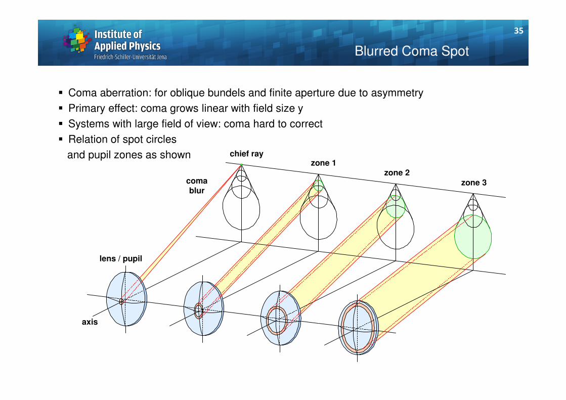
Blurred Coma Spot
� Coma aberration: for oblique bundels and finite aperture due to asymmetry
� Primary effect: coma grows linear with field size y
� Systems with large field of view: coma hard to correct
� Relation of spot circles
and pupil zones as shown chief rayzone 1
zone 3
zone 2comablur
lens / pupil
axis
35

Distortion Example: 10%
Ref : H. Zügge
� What is the type of degradation of this image ?
� Sharpness good everywhere !
36

Distortion Example: 10%
Ref : H. Zügge
� Image with sharp but bended edges/lines
� No distortion along central directions
37

� Purely geometrical deviations without any blurr
� Distortion corresponds to spherical aberration of the chief ray
� Important is the location of the stop:
defines the chief ray path
� Two primary types with different sign:
1. barrel, D < 0
front stop
2. pincushion, D > 0
rear stop
� Definition of local
magnification
changes
Distortion
pincussion
distortion
barreldistortion
object
D < 0
D > 0
lens
rear
stop
imagex
x
y
y
y'
x'
y'
x'
front stop
ideal
idealreal
y
yyD
'
'' −=
38

� Non-symmetrical systems:
Generalized distortion types
� Correction complicated
General Distortion Types
original
anamorphism, a10
x
keystone, a11
xy
1. orderlinear
2. orderquadratic
3. order
cubic
line bowing, a02
y2
shear, a01
y
a20
x2
a30
x3 a21
x2y a12
xy2 a03
y3
39

Axial Chromatical Aberration
∆ s s sCHL F C' ' '' '
= −
white
H'
s'F'
s'
s'
e
C'green
red
blue
� Axial chromatical aberration:
Higher refractive index in the blue results in a shorter intersection length for a single lens
� The colored images are defocussed along the axis
� Definition of the error: change in image location /
intersection length
� Correction needs several glasses with different dispersion
40

s∆∆∆∆
λλλλ
e C'F'
Axial Chromatical Aberration
� Simple achromatization / first order
correction:
- two glasses with different dispersion
- equal intersection length for outer
wavelengths (blue F', red C')
- residual deviation for middle wavelength
(green e)
� Residual erros in image location:
secondary spectrum
� Apochromat:
- coincidence of the image location
for at least 3 wavelengths
- three glasses necessary, only with
anomal partial dispersion
(exceptions possible)
white
H'
s'F'
s'
s'
e
C'
green
redblue
secondary
spectrum
41

Axial Chromatical Aberration
� Longitudinal chromatical aberration for a single lens
� Best image plane changes with wavelength
Ref : H. Zügge
42

stop
red
blue
reference
image
plane
y'CHV
'' ''' CFCHV yyy −=∆
e
CF
CHVy
yyy
'
''' '' −=∆
Chromatic Variation of Magnification
� Lateral chromatical aberration:
Higher refractive index in the blue results in a stronger
ray bending of the chief ray for a single lens
� The colored images have different size,
the magnification is wavelength dependent
� Definition of the error: change in image height/magnification
� Correction needs several glasses with different dispersion
� The aberration strongly depends on the stop position
43

� Impression of CHV in real images
� Typical colored fringes blue/red at edges visible
� Color sequence depends on sign of CHV
Chromatic Variation of Magnification
original
withoutlateral
chromaticaberration
0.5 % lateralchromatic
aberration
1 % lateralchromatic
aberration
44

Summary of Important Topics
� There are different representations for aberrations
� Transverse aberrations are the most useful type
� Aberrations can be expanded into a Taylor series for field and aperture coordinate
� There are 7 primary aberrations (Seidel) of 3rd order; spherical aberration, coma,
astigmatism, field curvature, distortion, axial chromatical, lateral chromatical
� In the Seidel definition, surface and lens contributions are additive
� Lens bending strongly changes aberration contribution due to variation of the incidence
angles
� There are special setups with vanishing spherical aberration,
important are aplanatic surfaces
� The image surface has two different equivalent representations:
1. tangential and sagittal image shell
2. astigmatism (difference) and field curvature (mean)
� Chromatic aberrations: axial and lateral, same size as monochromatic primary aberrations
45

Outlook
Next lecture: Part 8 – Wave optical aberrations
Date: Wednesday, 2012-04-25
Contents: 8.1 Introduction, phase and optical path length
8.2 Definition of wave aberrations
8.3 Power expansion of the wave aberration
8.4 Zernike polynomials
8.5 Measurement of wave aberrations
8.6 Special aspects
46

Outlook
Next lecture: Part 7 – Geometrical aberrations
Date: Wednesday, 2012-06-06
Contents: 7.1 Representations
7.2 Power expansion of aberrations
7.3 Surface contributions
7.4 Primary monochromatic aberrations
7.5 Chromatical aberrations
47
Related Documents
![Power Factor Correction Products - Max Group Factor Correction Products Description Minimum Ordering Quantity (No.) Reference Unit MRP [`] Varplus Standard Duty (S Duty) 440V Range](https://static.cupdf.com/doc/110x72/5ae474457f8b9a7b218e6ad8/power-factor-correction-products-max-factor-correction-products-description-minimum.jpg)