rsif.royalsocietypublishing.org Research Cite this article: Caluwaerts K, Despraz J, Is¸c ¸en A, Sabelhaus AP, Bruce J, Schrauwen B, SunSpiral V. 2014 Design and control of compliant tensegrity robots through simulation and hardware validation. J. R. Soc. Interface 11: 20140520. http://dx.doi.org/10.1098/rsif.2014.0520 Received: 16 May 2014 Accepted: 12 June 2014 Subject Areas: biomechanics, biomimetics Keywords: tensegrity, bioinspired locomotion, central pattern generators, compliant robotics, soft robotics, planetary exploration Author for correspondence: Ken Caluwaerts e-mail: [email protected] Electronic supplementary material is available at http://dx.doi.org/10.1098/rsif.2014.0520 or via http://rsif.royalsocietypublishing.org. Design and control of compliant tensegrity robots through simulation and hardware validation Ken Caluwaerts 1,2 , Je ´re ´mie Despraz 1,3 , Atıl Is¸c ¸en 1,4 , Andrew P. Sabelhaus 1,5 , Jonathan Bruce 1,6 , Benjamin Schrauwen 2 and Vytas SunSpiral 1,7 1 Dynamic Tensegrity Robotics Lab, NASA Ames Research Center, Moffett Field, CA, USA 2 Reservoir Lab, Department of Electronics and Information Systems, Ghent University, Ghent, Belgium 3 Biorobotics Laboratory, Ecole Polytechnique Fe ´de ´rale de Lausanne (EPFL), Lausanne, Switzerland 4 School of Electrical Engineering & Computer Science, Oregon State University, Corvallis, OR, USA 5 Berkeley Institute of Design, University of California Berkeley, Berkeley, CA, USA 6 USRA, University of California Santa Cruz, Santa Cruz, CA, USA 7 SGT Inc., NASA Ames Intelligent Robotics Group, Moffett Field, CA, USA To better understand the role of tensegrity structures in biological systems and their application to robotics, the Dynamic Tensegrity Robotics Lab at NASA Ames Research Center, Moffett Field, CA, USA, has developed and validated two software environments for the analysis, simulation and design of tensegrity robots. These tools, along with new control methodologies and the modular hardware components developed to validate them, are pre- sented as a system for the design of actuated tensegrity structures. As evidenced from their appearance in many biological systems, tensegrity (‘ten- sile–integrity’) structures have unique physical properties that make them ideal for interaction with uncertain environments. Yet, these characteristics make design and control of bioinspired tensegrity robots extremely challen- ging. This work presents the progress our tools have made in tackling the design and control challenges of spherical tensegrity structures. We focus on this shape since it lends itself to rolling locomotion. The results of our analyses include multiple novel control approaches for mobility and terrain interaction of spherical tensegrity structures that have been tested in simulation. A hard- ware prototype of a spherical six-bar tensegrity, the Reservoir Compliant Tensegrity Robot, is used to empirically validate the accuracy of simulation. 1. Introduction Prior work has investigated the unique structural properties of tensegrity systems, their role in biology and control strategies for different tensegrity mor- phologies. One of the centres for this research is NASA Ames Research Center, Moffett Field, CA, USA, where there is interest in these systems for planetary exploration missions. 1.1. Tensegrity structures Tensegrity structures are composed of compression elements encompassed within a network of tensional elements; consequently, each element experiences either pure compression or pure tension. This allows individual elements to be extremely lightweight, as designs do not need to resist bending or shear forces. Active motion in tensegrity structures can be performed with minimal energy expenditure as actuators work linearly along load paths in tension elements, avoiding torques caused by long lever arms of traditional robotic designs. A unique property of tensegrity structures is how they internally distribute forces. As there are no leverarms, forces do not magnify around joints or other common points of failure. Rather, externally applied forces distribute through the structure via multiple load paths, creating system-level mechanical robustness and tolerance to forces applied from any direction or failure of individual & 2014 The Author(s) Published by the Royal Society. All rights reserved. on June 21, 2018 http://rsif.royalsocietypublishing.org/ Downloaded from

Welcome message from author
This document is posted to help you gain knowledge. Please leave a comment to let me know what you think about it! Share it to your friends and learn new things together.
Transcript

on June 21, 2018http://rsif.royalsocietypublishing.org/Downloaded from
rsif.royalsocietypublishing.org
ResearchCite this article: Caluwaerts K, Despraz J,
Iscen A, Sabelhaus AP, Bruce J, Schrauwen B,
SunSpiral V. 2014 Design and control of
compliant tensegrity robots through simulation
and hardware validation. J. R. Soc. Interface
11: 20140520.
http://dx.doi.org/10.1098/rsif.2014.0520
Received: 16 May 2014
Accepted: 12 June 2014
Subject Areas:biomechanics, biomimetics
Keywords:tensegrity, bioinspired locomotion, central
pattern generators, compliant robotics,
soft robotics, planetary exploration
Author for correspondence:Ken Caluwaerts
e-mail: [email protected]
Electronic supplementary material is available
at http://dx.doi.org/10.1098/rsif.2014.0520 or
via http://rsif.royalsocietypublishing.org.
& 2014 The Author(s) Published by the Royal Society. All rights reserved.
Design and control of complianttensegrity robots through simulationand hardware validation
Ken Caluwaerts1,2, Jeremie Despraz1,3, Atıl Iscen1,4, Andrew P. Sabelhaus1,5,Jonathan Bruce1,6, Benjamin Schrauwen2 and Vytas SunSpiral1,7
1Dynamic Tensegrity Robotics Lab, NASA Ames Research Center, Moffett Field, CA, USA2Reservoir Lab, Department of Electronics and Information Systems, Ghent University, Ghent, Belgium3Biorobotics Laboratory, Ecole Polytechnique Federale de Lausanne (EPFL), Lausanne, Switzerland4School of Electrical Engineering & Computer Science, Oregon State University, Corvallis, OR, USA5Berkeley Institute of Design, University of California Berkeley, Berkeley, CA, USA6USRA, University of California Santa Cruz, Santa Cruz, CA, USA7SGT Inc., NASA Ames Intelligent Robotics Group, Moffett Field, CA, USA
To better understand the role of tensegrity structures in biological systems
and their application to robotics, the Dynamic Tensegrity Robotics Lab at
NASA Ames Research Center, Moffett Field, CA, USA, has developed and
validated two software environments for the analysis, simulation and
design of tensegrity robots. These tools, along with new control methodologies
and the modular hardware components developed to validate them, are pre-
sented as a system for the design of actuated tensegrity structures. As
evidenced from their appearance in many biological systems, tensegrity (‘ten-
sile–integrity’) structures have unique physical properties that make them
ideal for interaction with uncertain environments. Yet, these characteristics
make design and control of bioinspired tensegrity robots extremely challen-
ging. This work presents the progress our tools have made in tackling the
design and control challenges of spherical tensegrity structures. We focus on
this shape since it lends itself to rolling locomotion. The results of our analyses
include multiple novel control approaches for mobility and terrain interaction
of spherical tensegrity structures that have been tested in simulation. A hard-
ware prototype of a spherical six-bar tensegrity, the Reservoir Compliant
Tensegrity Robot, is used to empirically validate the accuracy of simulation.
1. IntroductionPrior work has investigated the unique structural properties of tensegrity
systems, their role in biology and control strategies for different tensegrity mor-
phologies. One of the centres for this research is NASA Ames Research Center,
Moffett Field, CA, USA, where there is interest in these systems for planetary
exploration missions.
1.1. Tensegrity structuresTensegrity structures are composed of compression elements encompassed
within a network of tensional elements; consequently, each element experiences
either pure compression or pure tension. This allows individual elements to be
extremely lightweight, as designs do not need to resist bending or shear forces.
Active motion in tensegrity structures can be performed with minimal energy
expenditure as actuators work linearly along load paths in tension elements,
avoiding torques caused by long lever arms of traditional robotic designs.
A unique property of tensegrity structures is how they internally distribute
forces. As there are no lever arms, forces do not magnify around joints or other
common points of failure. Rather, externally applied forces distribute through
the structure via multiple load paths, creating system-level mechanical robustness
and tolerance to forces applied from any direction or failure of individual
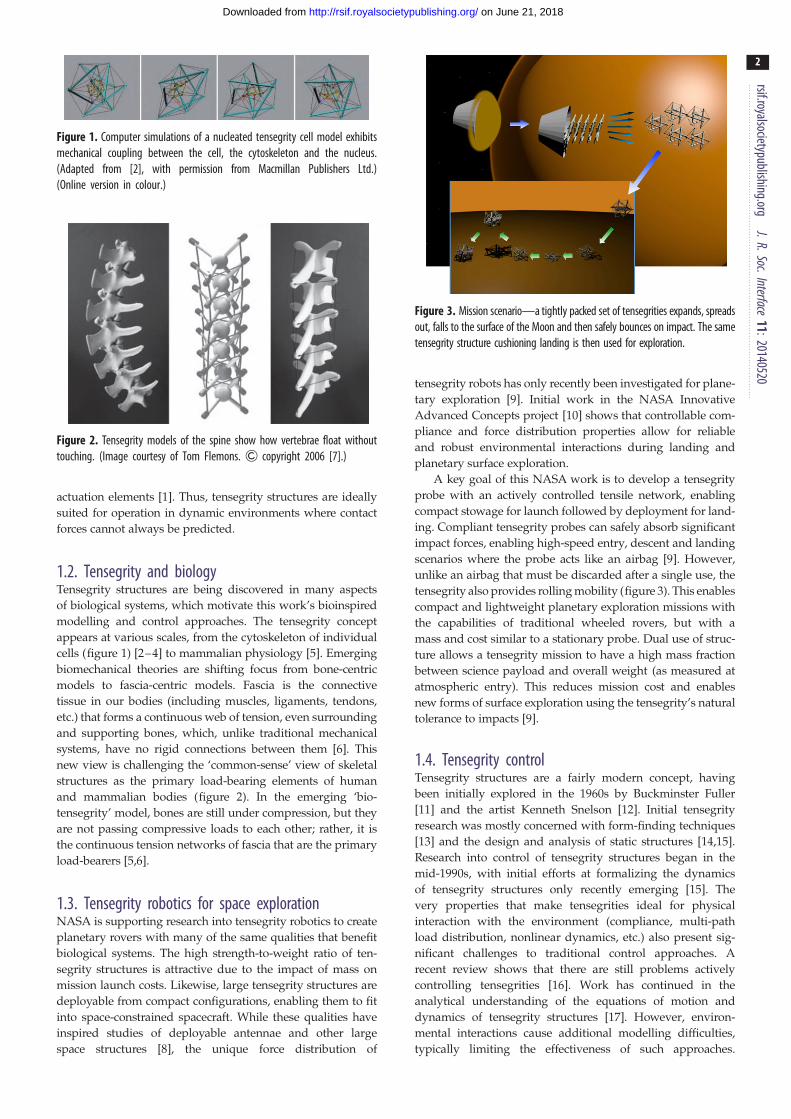
Figure 1. Computer simulations of a nucleated tensegrity cell model exhibitsmechanical coupling between the cell, the cytoskeleton and the nucleus.(Adapted from [2], with permission from Macmillan Publishers Ltd.)(Online version in colour.)
Figure 2. Tensegrity models of the spine show how vertebrae float withouttouching. (Image courtesy of Tom Flemons. & copyright 2006 [7].)
Figure 3. Mission scenario—a tightly packed set of tensegrities expands, spreadsout, falls to the surface of the Moon and then safely bounces on impact. The sametensegrity structure cushioning landing is then used for exploration.
rsif.royalsocietypublishing.orgJ.R.Soc.Interface
11:20140520
2
on June 21, 2018http://rsif.royalsocietypublishing.org/Downloaded from
actuation elements [1]. Thus, tensegrity structures are ideally
suited for operation in dynamic environments where contact
forces cannot always be predicted.
1.2. Tensegrity and biologyTensegrity structures are being discovered in many aspects
of biological systems, which motivate this work’s bioinspired
modelling and control approaches. The tensegrity concept
appears at various scales, from the cytoskeleton of individual
cells (figure 1) [2–4] to mammalian physiology [5]. Emerging
biomechanical theories are shifting focus from bone-centric
models to fascia-centric models. Fascia is the connective
tissue in our bodies (including muscles, ligaments, tendons,
etc.) that forms a continuous web of tension, even surrounding
and supporting bones, which, unlike traditional mechanical
systems, have no rigid connections between them [6]. This
new view is challenging the ‘common-sense’ view of skeletal
structures as the primary load-bearing elements of human
and mammalian bodies (figure 2). In the emerging ‘bio-
tensegrity’ model, bones are still under compression, but they
are not passing compressive loads to each other; rather, it is
the continuous tension networks of fascia that are the primary
load-bearers [5,6].
1.3. Tensegrity robotics for space explorationNASA is supporting research into tensegrity robotics to create
planetary rovers with many of the same qualities that benefit
biological systems. The high strength-to-weight ratio of ten-
segrity structures is attractive due to the impact of mass on
mission launch costs. Likewise, large tensegrity structures are
deployable from compact configurations, enabling them to fit
into space-constrained spacecraft. While these qualities have
inspired studies of deployable antennae and other large
space structures [8], the unique force distribution of
tensegrity robots has only recently been investigated for plane-
tary exploration [9]. Initial work in the NASA Innovative
Advanced Concepts project [10] shows that controllable com-
pliance and force distribution properties allow for reliable
and robust environmental interactions during landing and
planetary surface exploration.
A key goal of this NASA work is to develop a tensegrity
probe with an actively controlled tensile network, enabling
compact stowage for launch followed by deployment for land-
ing. Compliant tensegrity probes can safely absorb significant
impact forces, enabling high-speed entry, descent and landing
scenarios where the probe acts like an airbag [9]. However,
unlike an airbag that must be discarded after a single use, the
tensegrity also provides rolling mobility (figure 3). This enables
compact and lightweight planetary exploration missions with
the capabilities of traditional wheeled rovers, but with a
mass and cost similar to a stationary probe. Dual use of struc-
ture allows a tensegrity mission to have a high mass fraction
between science payload and overall weight (as measured at
atmospheric entry). This reduces mission cost and enables
new forms of surface exploration using the tensegrity’s natural
tolerance to impacts [9].
1.4. Tensegrity controlTensegrity structures are a fairly modern concept, having
been initially explored in the 1960s by Buckminster Fuller
[11] and the artist Kenneth Snelson [12]. Initial tensegrity
research was mostly concerned with form-finding techniques
[13] and the design and analysis of static structures [14,15].
Research into control of tensegrity structures began in the
mid-1990s, with initial efforts at formalizing the dynamics
of tensegrity structures only recently emerging [15]. The
very properties that make tensegrities ideal for physical
interaction with the environment (compliance, multi-path
load distribution, nonlinear dynamics, etc.) also present sig-
nificant challenges to traditional control approaches. A
recent review shows that there are still problems actively
controlling tensegrities [16]. Work has continued in the
analytical understanding of the equations of motion and
dynamics of tensegrity structures [17]. However, environ-
mental interactions cause additional modelling difficulties,
typically limiting the effectiveness of such approaches.

rsif.royalsociety
3
on June 21, 2018http://rsif.royalsocietypublishing.org/Downloaded from
Consequently, successful demonstrations of tensegrity mobi-
lity have primarily used non-analytical methods [1,18–20].
Our approach to these problems is therefore to develop control
algorithms based on central pattern generators (CPGs),
distributed learning and genetic algorithms instead of more
traditional control approaches.
publishing.orgJ.R.Soc.Interface
11:20140520
1.4.1. Central pattern generatorsCPGs are neural circuits found in both vertebrate and invert-
ebrate animals that produce rhythmic patterns of neural
activity without receiving rhythmic inputs. CPGs have been
studied from a biological perspective and have been used exten-
sively in robotics [21]. The term central indicates that rhythms of
the CPG are not driven by sensory input, but are self-generated.
CPGs are the fundamental building blocks for locomotor neural
circuits in many animals and are also key to other fundamental
rhythmic activities such as chewing, breathing and digesting.
Recent research shows a close relationship between CPGs and
motion primitives in the spine that enable both rhythmic and
discrete motions [22]. Alongside their biological inspiration
for use in robotic motion, CPGs present several interesting
and useful properties including distributed control, robustness
to perturbations, inherent tolerance to redundancies, fast con-
trol loops and the ability to modulate locomotion by simple
control signals.
CPGs are therefore well suited for controlling tensegrities
[23] and other biomimetic structures [24]. Additionally, there
is intuition for pairing tensegrity robots with CPG networks:
the dynamics of physical forces propagating through a tense-
grity structure are similar to the dynamics of control patterns
propagating through CPG networks.
1.4.2. Evolutionary algorithmsInstead of defining a control policy directly, evolutionary algor-
ithms can be used to learn a control policy. This is accomplished
through an iterative cycle, where in simulation a control policy
is run and evaluated, and this evaluation is fed back into
the genetic algorithm so that it can improve the control
policy. Evolutionary algorithms have the following advantages:
(1) Complex, nonlinear control policies can be learned.
(2) Underlying dynamics need not be known.
(3) Control policies can be learned or parameters of existing
control policies can be optimized.
(4) Distributed learning can be used to scale to larger
tensegrities and to accelerate learning.
Moreover, coevolutionary algorithms provide distributed
learning for multi-agent problems [25]. Each component can
individually learn a control policy that decides how to
actuate its individual end cap in such a way that global
performance is maximized [26]. Challenges controlling ten-
segrity robots using traditional approaches have led some
researchers to consider biologically inspired evolutionary or
coevolutionary algorithms [1,27–29].
1.5. OutlineThis paper is organized as follows: §2 introduces our simu-
lators and hardware platform; §3 presents our simulator
validation results; §4 describes our various control strategies;
and §5 discusses our future work and our results and
control strategies in context of other work. And last, §6
presents our conclusion.
2. Systems and modelsWe introduce three systems to evaluate the design and con-
trol of tensegrity structures. The first two are simulation
environments, while the third is an untethered, lightweight
robot prototype.
2.1. Spring – cable assembliesAll tensile members of the structures we study in this work
are compliant and we refer to them as spring–cable assemblies.
Although various implementations are possible, all spring–
cable assemblies in this work can be modelled as a zero
rest-length passive spring in series with a non-elastic cable.
The tension on spring–cable assembly i is given by
fi ¼ ki max (kpi,0 � pi,1k � ‘i, 0), (2:1)
where ki is the spring stiffness, kpi,0 � pi,1k is the Euclidean
distance between the attachments of the spring–cable assem-
bly and ‘i is the cable length. Actuated members have a
controllable rest length ‘i.
2.2. Euler – Lagrange simulatorWe extended the Euler–Lagrange formulation described in
Skelton’s reference work on tensegrity systems by adding
support for ground contacts and gravity [15]. In Skelton’s
work, the tensegrity structure struts are modelled as cylin-
ders with infinitesimal radius. Strut-to-strut contacts are
not modelled, which is an acceptable approximation for
NASA-scale missions.
We found that this environment provides particularly accu-
rate results for two types of experiments: tests of structural
forces and tests of effective structural stiffness. This simulator
is used for payload acceleration prediction during impacts
from drop tests, as well as stiffness analyses and form-finding.
However, its simple underlying model makes it unsuited for
the study of complex environmental interactions.
2.3. NASA Tensegrity Robotics ToolkitOur main simulation environment, the NASA Tensegrity
Robotics Toolkit (NTRT), is built on the discrete time Bullet
Physics engine (a game physics simulator) [30].
As game physics requires real-time simulation, Bullet is
designed to handle collisions without excessive processing
power. However, the Bullet physics library does not currently
provide models of ropes, cables or springs with realistic
material properties and stress analysis. Instead of using
these default soft body models, we built an additional library
to simulate spring–cable assemblies as two-point tensional
elements that apply directional forces to rigid bodies.
This approach gives the ability to calculate the amount of
stretch and tension for each simulated cable, as well as the
force exerted to the bodies, using more mathematically rigorous
models. A current limitation of this method is that the cables do
not exist in the simulation world as physical bodies. Thus, their
collisions and interaction with rigid bodies are not simulated.
For locomotion tasks and terrain types we have explored so
far, this is not a problem, but will be addressed in the future
to simulate more extreme terrain interactions.

Figure 4. ReCTeR: an untethered, highly compliant, spherical tensegrityrobot. Top left: deployed robot. (Credit: NASA Ames/Eric James.) Centreright: active folding. Bottom: ReCTeR rolling from right to left.
rsif.royalsocietypublishing.orgJ.R.Soc.Interface
11:20140520
4
on June 21, 2018http://rsif.royalsocietypublishing.org/Downloaded from
2.4. PrototypeIn addition to these two software environments, a physical
prototype of the six-bar tensegrity was constructed. Reservoir
Compliant Tensegrity Robot (ReCTeR) is a highly compliant,
lightweight (1.1 kg), underactuated tensegrity icosahedron
robot, as shown in figure 4. The robot’s 24 outer tensile
elements are passive spring–cable assemblies with low-
stiffness springs (28.4 N m21) under moderate pretension
(�10 N). Six actuated spring–cable assemblies run through
the robot connecting active and passive end caps (also see
§2.5). Their rest length is adjusted by a rotational DC motor
(4.5 W, 4.4 : 1 gear ratio) that spins a snag-resistant bobbin
(5.5 mm diameter). The other end of the cable attaches to a
stiffer spring (81 N m21) affixed to a passive end cap. We
use low-stiffness springs to allow active folding (figure 4)
without plastic deformation of the 24 passive tensile
members or excessive motor power requirements.
The six active spring–cables run through the robot and
connect non-parallel struts in an advantageous way. Stiffness
analysis revealed that this pattern allows for large shape
deformations with low motor power requirements. As a con-
sequence of low spring stiffnesses, the lowest natural
frequencies of oscillatory modes for the structure are of the
order of a few hertz.
Sensing and feedback control are achieved by 24 tension
sensors using strain gauges, six ground reaction-force sensors
and three six-DOF inertial measurement units distributed
evenly among the actuated end caps. To allow dynamic
motion and rolling, each self-contained strut holds a hardware
module with battery power and wireless communication. The
battery is mounted at the centre of the strut to minimize the
moment of inertia around its longitudinal axis. This makes
ReCTeR fully untethered.
2.5. Robot modelsOur control methods are implemented on platforms with
varying configurations. Figure 5 shows the three tensegrity
icosahedra analysed in this paper.
We put a particular emphasis on spherical icosahedron
tensegrities. This symmetric configuration provides a large
interior volume with a moderate number of members
and can be folded easily. It lends itself naturally to rolling
locomotion because of its triangular faces. Additionally,
tensile-member failure will result in reduced locomotion
capabilities instead of full failure, due to its redundant
number of tensile members [31].
The basic tensegrity icosahedron is shown in figure 5a.
This structure has 24 spring–cable assemblies and six rigid
rods. The spring–cable assemblies are also referred to as
outer-shell elements.
A tensegrity icosahedron with a payload is displayed in
figure 5b. This structure has an additional 12 spring–cable
assemblies to suspend the payload in the centre of the
robot. We also refer to these as inner members.
Figure 5c displays the model ReCTeR’s configuration with
actual dimensions. ReCTeR has the basic tensegrity icosahedron
configuration with six extra actuated spring–cable assemblies.
3. Validation of simulations3.1. Experimental set-upTo track the full state of the robot, an active marker motion
capture set-up was used. Passive struts were fitted with
two markers, and active struts received three markers.
3.2. KinematicsThe forward kinematics of the Euler–Lagrange and NTRT
simulators were compared against motion capture data
from ReCTeR.
The six-strut ReCTeR robot was placed on one of its tri-
angular faces and two top spring–cable assemblies were
actuated, as shown in figure 6. We tracked vertical displace-
ment of an end cap not directly actuated by one of these
two members. The incident strut was suspended in air by a
total of 10 springs.
Lengths of the two actuated spring assemblies were
varied from the point of no tension in the given configuration
(slack) to 0.32 m beyond this length. Each range was sampled
at 10 equally spaced lengths, resulting in 100 measurement
positions. Ranges were manually tuned to maximally
deform the robot without causing it to roll. This experiment
was repeated three times with no meaningful difference in
observed displacements.
The average observed difference between motion capture
data and the Euler–Lagrange simulator was 6.5 mm. For
NTRT, we obtained an average error of 15 mm (0.5% and
1.3% of ReCTeR’s diameter).
3.3. DynamicsNext, we compared the dynamics of the NTRT simulator with
the ReCTeR hardware. This experiment was designed for two
purposes: first, to verify that the simulator can replicate
ground interactions; and second, that it can simulate conversion
of potential energy into kinematic energy when a spring is
released. The experimental set-up is shown in figure 7. The
robot initially has a non-minimal ground contact (four end
caps on the ground instead of just three), and three actuated
springs are tensioned. Next, one of the tensioned, actuated
springs is loosened by its actuator, causing the robot to roll over.
As the experiment also depends on ReCTeR’s initial state, the
observed initial state from the motion capture data was copied
to the NTRT simulator. The ReCTeR model in the NTRT simu-
lator was then released from this initial configuration, allowing
it to reach the simulated, predicted equilibrium. Recorded
motor positions from the physical test were then applied into
the simulator, causing a similar roll-over motion.

(a) (b) (c)
payload
strutsshell spring–cable assembliespayload spring–cable assembliesReCTeR actuated spring–cable assemblies
1 m
Figure 5. The various tensegrity configurations used in this paper. (a) Tensegrity icosahedron with only outer-shell members. (b) Tensegrity icosahedron with apayload by inner elements. (c) ReCTeR configuration with passive outer-shell and actuated spring – cable assemblies. (Online version in colour.)
0.8
0.7
0.6
0.5
Z(m
)
Y (m)
0.4
0.3
0.2
0.1
–0.3–0.2–0.1 00.1
0.2 0.3 0.4 0.6
E-L
actuator 1 position (m) actuator 2 position (m)
0.35 0.050.10 0.150.20 0.25
0.300.35–0.10
node
ver
tical
dis
plac
emen
t (m
)
–0.08
–0.06
–0.04
–0.02
0
0.02
0.04
0.06
0.300.250.200.150.100.05
actuator 1 position (m) actuator 2 position (m)
0.35 0.050.10 0.150.20 0.25
0.300.35–0.10
node
ver
tical
dis
plac
emen
t (m
)–0.08
–0.06
–0.04
–0.02
0
0.02
0.04
0.06
0.300.250.200.150.100.05
NTRT
actuator 1 position (m) actuator 2 position (m)
0.35 0.050.10 0.150.20 0.25
0.300.35–0.10
node
ver
tical
dis
plac
emen
t (m
)
–0.08
–0.06
–0.04
–0.02
0
0.02
0.04
0.06
0.300.250.200.150.100.05
motion capture
0.40.2
X (m)
0–0.2
(b)(a)
(c) (d )
Figure 6. (a – d) Kinematic comparison of Euler – Lagrange (E-L) and NTRT simulators and ReCTeR motion capture data. (a) shows the experimental set-up. The restlength of two actuated spring – cable assemblies (dashed lines) is modified. The full range of tracked end-cap motion during the experiment is shown in transparentyellow (convex hull). The end caps indicated by small squares are on the ground. (b – d) show vertical displacement of the end cap indicated by the large black dotin (a) as a function of the lengths of the two actuated cables. The end cap where we trace the displacement is not directly actuated and is floating. The nodaldisplacement as a function of the actuator position is nonlinear, even for modest displacements. Note that the left-most point (0.05, 0.05, 0) is the reference point;displacements are relative to this initial state. (Online version in colour.)
rsif.royalsocietypublishing.orgJ.R.Soc.Interface
11:20140520
5
on June 21, 2018http://rsif.royalsocietypublishing.org/Downloaded from
4. Locomotion controlOnce it had been determined that the NTRT simulator mod-
elled these robotic dynamics reasonably well, locomotion
experiments were performed with tensegrity robots in both
simulation and hardware. The algorithms described in §4.1
apply to various configurations, but are presented here in
simulation for the first configuration, as shown in figure 5
with 1.5 m rods, weighing 15 kg. The controls in §4.2 were
applied to simulations of the second configuration. Section
4.3 presents hardware results on ReCTeR and a comparison
of those results with previously simulated implementations.
Appendix A provides a summary of the control methods in
this work and an overview of related work.
4.1. Coevolutionary controlThe first control method from our group is based on coevolu-
tionary algorithms [25]. We demonstrated successful rolling
locomotion of a tensegrity icosahedron with this technique

NT
RT
robo
t
t = 0 s t = 0.50 s t = 1.00 s t = 1.50 s t = 2.00 s t = 2.50 s
Figure 7. Comparing the dynamics of the robot and NTRT. The tensioned spring – cable assembly indicated by the dashed line is released (0.32 – 0.535 m at0.6 m s21), causing the robot to topple. Two other actuated members are also tensioned, while the other three actuated springs are at their initial lengths, resultingin two slack springs. We observed a time-averaged error of the end caps’ vertical positions of less than 5% of ReCTeR’s diameter for all end caps. (Online version incolour.)
05
101520253035
0 2000 4000 6000 8000 10 000 12 000
00.010.020.030.040.05
dist
ance
rol
led
(m)
failu
re r
ate
simulations
best policy
average failures
Figure 8. Distance covered by the robot in 60 s with distributed learning ofopen-loop controllers based on coevolutionary algorithms. Each of the 24outer-shell spring – cable assembly controllers has a different evolutionpool, but their combined behaviour is optimized. (Online version in colour.)
rsif.royalsocietypublishing.orgJ.R.Soc.Interface
11:20140520
6
on June 21, 2018http://rsif.royalsocietypublishing.org/Downloaded from
in the NTRT [29]. In this scheme, each spring–cable assembly
is active and has a controller that evolves independently
from the other controllers (i.e. in independent pools), but
cooperation is used to optimize behaviour of the entire
robot. The objective function for this maximization was set
to be ReCTeR’s distance travelled during a fixed amount
of time. The simplest implementation of this technique is
an optimization of open-loop control signals that are only a
function of time; sinusoidal functions performed well.
After this method was explored, the effects of different
complexities and frequencies of these open-loop signals
were analysed. More precisely, we optimized stepwise func-
tions with varying numbers of via points. This enables the
study of computational load and scaling properties needed
to estimate power consumption of various controllers, as
well as to investigate the effects of actuator failure. Figure 8
shows the learning curve of this process. In this case, opti-
mized rest-length signals had four via points. An analysis
of practical aspects of these results (power consumption,
actuator failure, etc.) is underway.
While these open-loop controllers demonstrated basic
rolling behaviour, they commonly failed in the presence of
external forces or unexpected terrain conditions. To solve
this problem, we developed a simple rolling algorithm that
uses ground-contact sensors located on the simulated end
caps. Preliminary results have shown steerable rolling on
various terrains.
This brief analysis of coevolutionary learning for icosahe-
dral tensegrity locomotion demonstrates that learning-based
controls can provide robust rolling locomotion without
analytical knowledge of the robot’s dynamics.
4.2. Bioinspired controlIn contrast to the direct learning technique presented above,
our second set of approaches is more designer-involved
and specific to this structure. State feedback was used to
increase rolling performance of the tensegrity robot with
payload simulated with the NTRT (figure 5).
The idea behind these control laws is to create torque by
moving the robot’s centre of mass with respect to the
ground-contact surface to cause the robot to roll, as illustrated
in figure 9. This motion is achieved with a two-layer control
architecture: the robot’s heading and speed are controlled by
displacement of the central payload using the inner spring–
cable assemblies, and motion is simplified by actuating the
outer shell.
Three control approaches test inner spring–cable
assemblies: reactive controls, inverse kinematics (IK)-based
controls and CPG-based controls. Outer spring–cable assem-
blies are controlled with hand-tuning. Actuation of the outer
shell reduces ground contacts, not directly influencing head-
ing or speed. This affects motion in several ways. First, it
allows for creation of greater torques with the same payload
displacement. Second, it smoothens rolling behaviour of
the structure by preventing discontinuities due to excessive
ground contact.
For each control approach, inputs were taken as functions
of the robotic state. The height of each strut was computed
using simulated omnidirectional distance sensors located at
the end of each rod. The height assigned to each spring–
cable assembly was computed as the average of the two
endpoints’ height. We understand that omnidirectional dis-
tance sensors can be difficult to realize in hardware; it is

N
mg
Figure 9. Regular icosahedron tensegrity shape with central payload(figure 5b). The highlighted contact surface with the ground creates a reac-tion force N (upwards arrow) that, at rest, balances the weight of thestructure, represented on the figure by the downwards arrow mg. Torqueis created on the whole structure when displacement of the centre ofmass from its rest position occurs. (Online version in colour.)
rsif.royalsocietypublishing.orgJ.R.Soc.Interface
11:20140520
7
on June 21, 2018http://rsif.royalsocietypublishing.org/Downloaded from
not practical to rely on the full state of the robot as input.
However, multiple solutions to this problem exist. An inter-
esting approach is to embed ground reaction-force sensors
in a protective soft cap on each rod end. A second possibility,
motivated by the separation principle of control theory [32],
is to estimate system states from other sources, such as
accelerometer and gyroscope measurements. This second
approach could be augmented with the knowledge that this
icosahedron robot often rolls over an edge of a face triangle
[20]. Finally, one could use a CPG to emulate rhythmic
activation of sensors, similar to the approach in §4.2.2.
The control for the outer-shell cables was designed to
tighten the bottom part of the structure when rolling, chan-
ging the lever arms of the gravitational force from the
robot’s centre of mass, requiring less force to induce a roll.
Typically in the presence of a slope, reduction of ground-
contact surface is sufficient to cause a roll down the slope.
In order to take this into account, we added a measure of
speed, which is computed as the dot product between the
centre-of-mass position and the robot’s overall heading direc-
tion vector. With this method, speed is a scalar number and
its sign depends on the robot’s heading (positive in the
desired direction and negative otherwise). Speed can then
be used as feedback to influence the spring actuator com-
mand. Rest lengths of the shell spring–cable assemblies are
computed using the following actuation rule:
_‘i ¼ ws(‘0 þmin (h2i , h2
0)� ‘i), speed � 0_‘i ¼ ws(�‘� ‘i), otherwise,
((4:1)
where hi is the height of spring–cable assembly i as measured
from the distance sensors; ‘i is its current rest length; ‘0, h0
and �‘ are constant parameters; and ws [ Rþ accounts for
the time scale where length corrections occur. ‘0 and h0 rep-
resent the offset-rest length of the spring and the maximum
height measurement. The parameter �‘ represents the default
rest lengths of the springs that, if given as a command to
all motors, puts the tensegrity in a stable position on the
ground. Input and output parameters of this control law
are updated continuously through feedback control. Impe-
dance control, which was adapted to tensegrities previously
[24,33], is used to modify spring–cable rest lengths.
4.2.1. Reactive controlsThe first technique for actuation of inner payload spring–
cable assemblies was the use of reactive controllers. We
note that the only controllable parameter is cable length.
The variables ‘i here are the rest length of the inner springs.
Global heading direction in a chosen inertial reference
frame is defined by the unit vector v and the orientation of
each spring in this same reference frame, represented by the
vector vi. For each inner spring–cable assembly, we use the
dot product di ¼ v � vi as feedback to control the position of
the payload as follows:
_‘i ¼ (‘0 þ dig� k pi,0 � pi,1 k )wr (4:2)
and ‘i(0) ¼ ‘0, (4:3)
where the weight wr determines reactivity of the system and
g , 0 is a fixed parameter. Thus, without any external pertur-
bation, the system has a stable equilibrium position at
‘0 þ dig. Rest length of the spring–cable assemblies where
the orientation aligns with the global heading is reduced.
Vice versa, springs pointing in the opposite direction are
elongated. The global result is displacement of the payload in
the direction of the heading vector, as shown in figure 10.
Note that the heading direction v can be chosen arbitrarily
and adjusted dynamically. This method resulted in stable
and smooth rolling gaits, allowing a roll of up to 1 m s21
(�1 body-length per second) over flat terrain. The robot
could also handle slopes up to 88, bumpy terrain, obstacles
and collisions.
The main disadvantage of the reactive method is the type
and amount of sensor feedback required to implement this
approach in hardware. This issue is addressed by the control
methods presented next, which are based on the same phys-
ical principle but require less feedback information.
4.2.2. Central pattern generator controlsCPGs have been successfully used in past tensegrity systems
[23]. Such controls are a feasible alternative to reactive con-
trollers that enable generation of regular motion patterns.
For this control, full-state information is used to generate
smooth motion under reactive controls. Then, resulting peri-
odic commands were stored as a stable limit cycle of a CPG.
Once this process completes, the tensegrity can be driven by
CPG output with much less feedback. We used an adaptive
frequency Hopf oscillator [34] during the learning phase
where the tensegrity was reactively control-driven. The
underlying dynamical system reads
_u ¼ g(m� (u2 þ g2))u� vgþ eb(t), (4:4)
_g ¼ g(m� (u2 þ g2))gþ vu (4:5)
and _v ¼ �eb(t)g
u2 þ g2, (4:6)
where u, g and v are state variables of the dynamical system,
g is a time constant, m is the target frequency and v is the
target pulsation of the signal. Note the element and time indi-
ces are dropped to simplify notation: u designates ui(t), with ithe index of the spring–cable assembly. The output u can

v2¢
v3¢
v4¢
v1¢
v v
v3
v2
v1
v4
�1(n) = �1
(n–1) – d
�2(n) = �2
(n–1) – d
�3(n) = �3
(n–1) + d
�4(n) = �4
(n–1) + d
Figure 10. Computation of new rest lengths according to the spring – cable assemblies’ individual orientations vi (time t (n – 1)). Length modification is indicated bycoloured lines, dashed red if reduced and light green if elongated. The resulting effect is displacement of the central payload in the desired direction v (timet(n) ¼ t(n�1) þ dt). (Online version in colour.)
rsif.royalsocietypublishing.orgJ.R.Soc.Interface
11:20140520
8
on June 21, 2018http://rsif.royalsocietypublishing.org/Downloaded from
synchronize to any periodic input signal b(t) and replaces the
feedback signal from the previous section,
di(t) ¼ ui(t): (4:7)
Once the signal is learned, time dependency of the pulsa-
tion is removed, i.e. v is held constant and a term
accounting for ground-contact coupling is added to the
dynamical system
_u ¼ g(m� (u2 þ g2))u� vg� hh(t), (4:8)
_g ¼ g(m� (u2 þ g2))gþ vu (4:9)
and _v ¼ 0, (4:10)
where h(t) denotes the height signal fed back by the
omnidirectional ranging sensors and h [ Rþ is a coeffi-
cient. This method has the advantage of requiring
minimal feedback and, thus, minimal computations. How-
ever, it is important to note that the dynamical system
runs on a much larger time scale than perturbations dis-
turbing the system. A tensegrity driven only by a CPG
would then, in the best case, only have a stable rolling
gait on a flat, obstacle-free terrain. Consequently, it is
necessary to include a second control method that works
on this smaller time scale and gives an appropriate
response to external perturbations.
4.2.3. Hybrid central pattern generator: inverse kinematicscontrols
The final control method we tested is a hybrid technique with
inverse kinematics. First, the position of the central payload
p ¼ ( px, py, pz) is defined as a function of the inner cable
lengths ‘ ¼ (‘1, :::, ‘n). We can write this as a small displacement
dp of the payload
d pi � pi(‘(0))þ
Xn
j¼1
@ pi(‘(0))
@‘jd‘j
þ 1
2
Xn
j¼1
Xn
k¼1
@2 pi(‘(0))
@‘j@‘kd‘jd‘k (4:11)
or
d pi � pi(‘(0))þ
�J(p(0))d‘
�i
þ 1
2d‘TH
�pi(‘
(0))�d‘, (4:12)
for i [ {x, y, z} and where H( pi) ¼ [@2 pi=@‘j@‘k] jk is the
Hessian matrix associated with pi and J ¼ ½@pi=@lj�ij.Considering equation (4.12), we additionally define
Dp ¼ dp� p(‘(0)) and f(d‘; Dp) as
fi(d‘; Dp) ¼�
J(p(0))d‘�
iþ 1
2d‘TH�
pi(‘(0))�d‘� D pi: (4:13)
Computation of the spring–cable rest-length changes d‘
for a desired payload displacement Dp corresponds to
finding the d‘ that cause f ¼ 0. As this last equation is
over-determined, nonlinear and might not possess a real sol-
ution, we employed a quasi-Newtonian iterative method to
approximate the solution. Starting from a candidate solution,
e.g. d‘0 ¼ 0, the next iteration is computed as
d‘kþ1 ¼ d‘k � J�1k f(d‘k; Dp) (4:14)
until convergence. J21 here denotes the Moore–Penrose
pseudo-inverse of the Jacobian defined by
J ¼ @ fi@(d‘j)
� �ij
: (4:15)
Note that this matrix is not the same as the one in the Taylor
expansion of p(‘).
The outputs of the IK algorithm j ¼ d‘1 (where 1 indi-
cates convergence) represent length corrections that have to
be made to reposition the payload at the desired location.
The outputs j can be used together with the adaptive fre-
quency oscillator as presented in §4.2.2. This approach is
inspired by two previous works by Ajallooeian et al. [35]
and Gay et al. [36]. We update j if and only if the payload
position lies on the opposite side of the robot’s centre of
mass, and we continuously adjust j with time according to
the following evolution rule:
d
dtj(t) ¼ �aj(t), (4:16)
0–10
0
10
20
30
40
50
60
20
reactive
CPG
CPG + lK
40x (m)
y(m
)
60 80
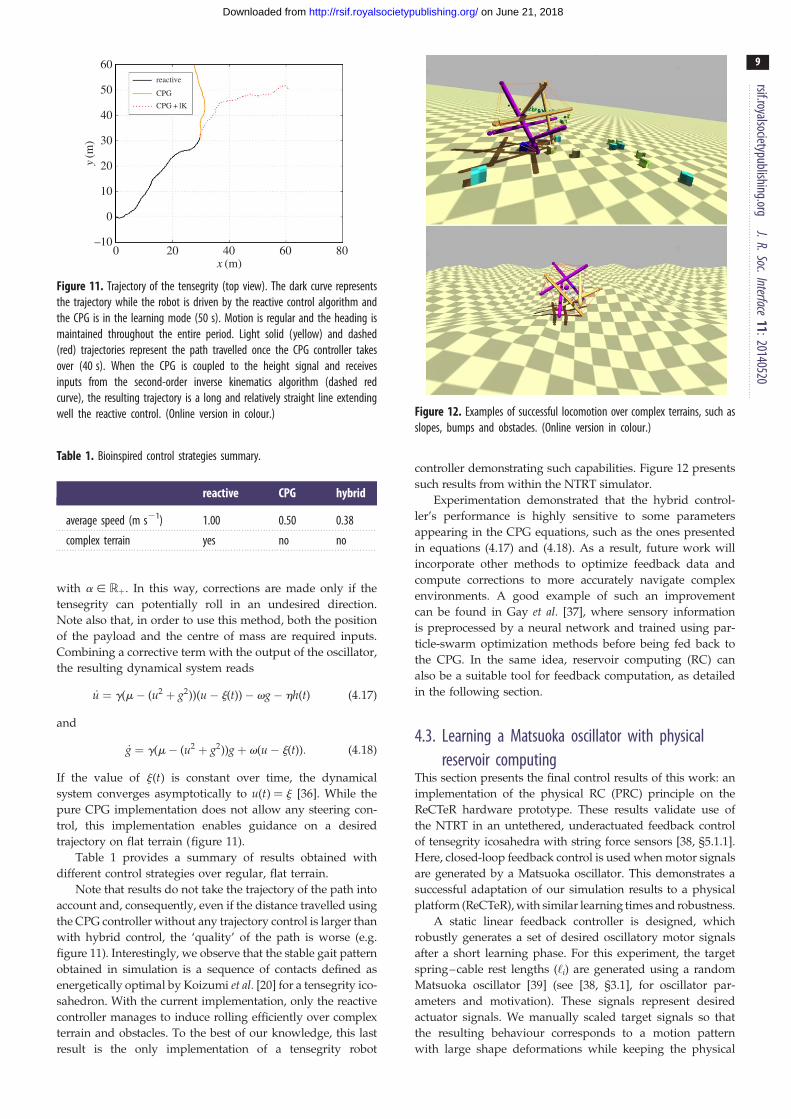
Figure 11. Trajectory of the tensegrity (top view). The dark curve representsthe trajectory while the robot is driven by the reactive control algorithm andthe CPG is in the learning mode (50 s). Motion is regular and the heading ismaintained throughout the entire period. Light solid (yellow) and dashed(red) trajectories represent the path travelled once the CPG controller takesover (40 s). When the CPG is coupled to the height signal and receivesinputs from the second-order inverse kinematics algorithm (dashed redcurve), the resulting trajectory is a long and relatively straight line extendingwell the reactive control. (Online version in colour.)
Table 1. Bioinspired control strategies summary.
reactive CPG hybrid
average speed (m s21) 1.00 0.50 0.38
complex terrain yes no no
Figure 12. Examples of successful locomotion over complex terrains, such asslopes, bumps and obstacles. (Online version in colour.)
rsif.royalsocietypublishing.orgJ.R.Soc.Interface
11:20140520
9
on June 21, 2018http://rsif.royalsocietypublishing.org/Downloaded from
with a [ Rþ. In this way, corrections are made only if the
tensegrity can potentially roll in an undesired direction.
Note also that, in order to use this method, both the position
of the payload and the centre of mass are required inputs.
Combining a corrective term with the output of the oscillator,
the resulting dynamical system reads
_u ¼ g(m� (u2 þ g2))(u� j(t))� vg� hh(t) (4:17)
and
_g ¼ g(m� (u2 þ g2))gþ v(u� j(t)): (4:18)
If the value of j(t) is constant over time, the dynamical
system converges asymptotically to u(t) ¼ j [36]. While the
pure CPG implementation does not allow any steering con-
trol, this implementation enables guidance on a desired
trajectory on flat terrain (figure 11).
Table 1 provides a summary of results obtained with
different control strategies over regular, flat terrain.
Note that results do not take the trajectory of the path into
account and, consequently, even if the distance travelled using
the CPG controller without any trajectory control is larger than
with hybrid control, the ‘quality’ of the path is worse (e.g.
figure 11). Interestingly, we observe that the stable gait pattern
obtained in simulation is a sequence of contacts defined as
energetically optimal by Koizumi et al. [20] for a tensegrity ico-
sahedron. With the current implementation, only the reactive
controller manages to induce rolling efficiently over complex
terrain and obstacles. To the best of our knowledge, this last
result is the only implementation of a tensegrity robot
controller demonstrating such capabilities. Figure 12 presents
such results from within the NTRT simulator.
Experimentation demonstrated that the hybrid control-
ler’s performance is highly sensitive to some parameters
appearing in the CPG equations, such as the ones presented
in equations (4.17) and (4.18). As a result, future work will
incorporate other methods to optimize feedback data and
compute corrections to more accurately navigate complex
environments. A good example of such an improvement
can be found in Gay et al. [37], where sensory information
is preprocessed by a neural network and trained using par-
ticle-swarm optimization methods before being fed back to
the CPG. In the same idea, reservoir computing (RC) can
also be a suitable tool for feedback computation, as detailed
in the following section.
4.3. Learning a Matsuoka oscillator with physicalreservoir computing
This section presents the final control results of this work: an
implementation of the physical RC (PRC) principle on the
ReCTeR hardware prototype. These results validate use of
the NTRT in an untethered, underactuated feedback control
of tensegrity icosahedra with string force sensors [38, §5.1.1].
Here, closed-loop feedback control is used when motor signals
are generated by a Matsuoka oscillator. This demonstrates a
successful adaptation of our simulation results to a physical
platform (ReCTeR), with similar learning times and robustness.
A static linear feedback controller is designed, which
robustly generates a set of desired oscillatory motor signals
after a short learning phase. For this experiment, the target
spring–cable rest lengths (‘i) are generated using a random
Matsuoka oscillator [39] (see [38, §3.1], for oscillator par-
ameters and motivation). These signals represent desired
actuator signals. We manually scaled target signals so that
the resulting behaviour corresponds to a motion pattern
with large shape deformations while keeping the physical

0
0.5
1.0ex
tern
al C
PG f
ract
ion
external CPG versus feedback controller fraction
0 50 100 150 200
200
400
600
vert
ical
pos
ition
(m
m) vertical position nodes
230 232 234 236 238 2400
200
400
600
vert
ical
posi
tion
(mm
) end of testing phase
0 2 4 6 8
200
400
600
time (s)
vert
ical
pos
ition
(m
m) start learning, mix feed-forward and feedback
time (s) time (s)80 82 84 86 88 900
200
400
600
end of learning phase
120 122 124 126 128 1300
200
400
600
constraining the robot190 192 194 196 198 2000
200
400
600
recovering motion after lifting the robot up
no learning, feedback controllearning, mixedfeed-forward/feedback control
(b) (c) (d) (e)(a)
(a) (b) (c)
(d)
(e)
Figure 13. Fast online learning of a static feedback controller for a Matsuoka oscillator on ReCTeR based on uncalibrated strain-gauge sensors. The top left plotshows the fraction of feed-forward versus feedback control. During learning, both feedback and feed-forward controllers (training signals) are active. The influence ofthe open-loop feed-forward controller decreases, and when its fraction is below 0.2, learning stops and only the trained feedback controller is active. The left plot onthe second row shows vertical coordinates (in millimetres) of the four end caps with the largest vertical displacements as a function of time. The five surroundingplots are details of this plot, showing different training and testing phases. (a) Fully open-loop control. (b) Switch from partially open-loop and feedback control tofull feedback control, learning stops. (c) We perturb the robot by pushing it down, preventing all movements. (d ) The feedback controller recovers after the robotwas lifted from the ground. (e) Behaviour of the robot after 250 s (170 s closed loop).
rsif.royalsocietypublishing.orgJ.R.Soc.Interface
11:20140520
10
on June 21, 2018http://rsif.royalsocietypublishing.org/Downloaded from
structure from moving too fast (as this impeded motion track-
ing). The resulting gait was a slow crawling motion that
allowed motion-capture tracking of the full experiment.
The algorithm proceeds by first applying target rest
lengths to actuators in an open-loop set-up, inducing the
robot to start moving. Next, online learning is applied to
approximate desired signals based on sensor readings. These
approximations are the feedback signals. The ratio of open-
loop to feedback signals is gradually decreased until signals
are generated by the feedback loop alone. At this point, the
robot will robustly maintain oscillatory patterns. The precise
equations and parameters used in the experiment are provided
in [38] and the electronic supplementary material.
In our prior simulation work, we used the term PRC to
describe how nonlinear computations, which are inherently
performed by a physical system, can be easily exploited to
simplify control of tensegrities [38]. PRC extends the RC con-
cept that, at its origin, is a simple technique to train recurrent
neural networks [40,41]. The common idea is that a system
with complex dynamics is perturbed externally, but is other-
wise left untouched. Instead, a simple readout mechanism is
trained to perform the desired computational task. A number
of related demonstrations have recently appeared in the soft
robotics fields, e.g. RC applied to a soft, simulated octopus
arm [42,43].
Controller feedback signals are obtained from ReCTeR’s 24
force transducers. As these sensors are mounted perpendicu-
larly to the robot’s struts, output values depend on the angle
of attack and tension of the attached spring–cable assembly.
Thus, the sensors provide a readout of the robot’s state, simi-
lar to state observations in RC. The robot’s behaviour was
evaluated using the motion-capture set-up described in §3.1.
Figure 13 shows the result of an experiment where we
first outsourced motor-signal generation to the feedback
loop by online learning of the feedback weights. After
training, we disturbed the system (lifting and constraining
the robot). In this case, the robot stops moving and switches
back to its original oscillatory mode when released, demon-
strating robustness of the learned feedback controller,
corresponding to our simulation results.
This experiment is a first demonstration of a simple,
robust feedback control strategy implemented in both hard-
ware and simulation for this class of untethered tensegrity
robots. Additionally, this result shows the usefulness of ten-
sion sensors for tensegrity control. These PRC experiments
are part of a continuous effort to develop low-level control-
lers for compliant robots that maximally exploit the robots’
proper dynamics and that allow mitigation of stringent
sensor requirements. We discussed many variations and
extensions on the hardware experiment presented here in
our prior simulation work [38].
5. Future workCurrent prototype hardware allows for multiple verification
levels of NTRT simulations. However, a more capable robot
design is required to implement fully dynamic controls
from the CPG systems and related work. ReCTeR has a maxi-
mum tension–force limit in its cables, as well as with the
number of cables actuated. We are currently working on a rede-
signed six-strut robot with twice the number of actuators, with
torque and velocity capabilities an order of magnitude higher
than ReCTeR [44]. This robot will be able to implement the
more advanced control schemes described in this paper.
Design of this new robot will also target payload protection,
a crucial feature for space exploration.
On the control side, one of our future goals is further inte-
gration of CPG and RC approaches, to maximally exploit the
advantages of both.

Table 2. Overview of various types of controllers for tensegrity robots and our experiments.
controller type main features type of locomotion
robot HW/SIM loop actuators sensors references
motion capture experiments untethered, underactuated control and simulator
validation
rolling, single flop and forward kinematics
ReCTeR HW and SIM open 6 motion capture §3
reactive controller with coevolution robust feedback controller with minimal assumptions steerable rolling over unknown terrain
icosahedron with/without payload SIM closed 24 touch sensors [45] and §4.1
bioinspired strategies (CPG) robust and bioinspired steerable rolling over unknown terrain
icosahedron with payload SIM closed 36 distance sensors §4.2
physical reservoir computing robust controller with uncalibrated sensors, link with
CPGs
crawling (HW), various (SIM)
ReCTeR (HW), icosahedron (SIM) HW and SIM closed 6 (HW), variable (SIM) tension sensors [38] and §4.3
sine waves with coevolution simple, distributed implementation forward rolling on flat terrain
icosahedron with/without payload SIM open 24/36 — [29]
stepwise functions with coevolution HW constraints and power consumption information forward rolling
icosahedron with/without payload SIM open 24 — §4.1
morphological communication communication through body dynamics, distributed
control
crawling like tension
sensors
[27]
15 bar tensegrity tower SIM closed 30
genetic algorithms first dynamic locomotion crawling
3 and 4 bar prisms SIM open 9/12 — [1]
pneumatic actuators insightful control, original hardware implementation rolling
icosahedron with pneumatic actuators HW open 24 — [19,20]
feedback nonlinear control control theory approach position/trajectory control
any tensegrity SIM closed all full state [15]
vibration driven cheap hardware, exploits body dynamics various
various HW open 1 — [46]
kinematic controllers tested on HW platforms and well studied none
various (constrained) HW and SIM both variable — [47,48]
CPG resonance entrainment demonstration of HW CPG control none
class 2 tensegrity beam HW and SIM both two linear actuators tension and position [23]
rsif.royalsocietypublishing.orgJ.R.Soc.Interface
11:20140520
11
on June 21, 2018http://rsif.royalsocietypublishing.org/Downloaded from
6. ConclusionTensegrity is a curious design concept, spanning art, science
and biology. This work presented the tensegrity workflow
developed at the NASA Ames Research Center. Our simulator
set-ups were described and demonstrated, and a new, highly
compliant, untethered tensegrity robot—ReCTeR—was used
to validate simulator set-ups in both dynamic and kinematic
situations. Next, various control strategies were presented,
based on evolutionary algorithms and CPGs, and a feedback
controller was implemented on the hardware platform to
demonstrate sensor capabilities. The biologically inspired con-
trol approaches we are exploring appear naturally suited
for biologically inspired tensegrity structures, due to their
matching nonlinear and oscillatory qualities.
An important aspect of this work is the creation of an Open
Source simulation environment (the NTRT) for tensegrity-
based mobility and manipulation controls research that has
now been validated against hardware. This simulation
environment enables us to develop an understanding of the
structure and qualities of successful control approaches.
Using evolutionary exploration of parameters for different
structural and biologically inspired control approaches, this
system can be used to develop performance-driven hardware
requirements, such as the forces experienced in the rods,
speed and torque requirements for actuators, elasticity con-
stants for springs and sensor requirements and placements.
Developing the right toolset and design workflow enables pro-
gress beyond tensegrity robots that merely move, and into a
realm where tensegrity systems purposefully interact with
the environment and execute tasks.
Acknowledgements. The authors would like to thank Ryan Adams, AdrianAgogino, Alice Agogino, Mostafa Ajallooeian, Lee Brownston, MichielD’Haene, Stephen R. Ellis, Tom Flemons, Terry Fong, Jeffrey Friesen,Auke Jan Ijspeert, George Korbel, Stephen Levin, Sophie Milam,

rsif.royalsocietypublishing.org
12
on June 21, 2018http://rsif.royalsocietypublishing.org/Downloaded from
Kyle Morse, Greg Orzech, In Won Park, Alexandra Pogue, Brian Tietz,Kagan Tumer, Tim Vets, Tim Waegeman, Kyunam Kim and the NASAAmes Intelligent Robotics Group.
Data accessibility. Our simulators and the ReCTeR robot hardwaredesigns are Open Source and can be obtained from our website:http://ti.arc.nasa.gov/tech/asr/intelligent-robotics/tensegrity/.
Funding statement. This research was supported by the European Com-mission’s FP7 programme under grant agreement no. 248311—AMARSi and the NASA Innovative Advanced Concepts program.K.C. was supported by a PhD fellowship of the Research Foun-dation—Flanders (FWO). Support also came from NSF GraduateResearch Fellowship no. DGE1106400, and from NASA Prime
Contract no. NAS2–03144 awarded to the University of California,Santa Cruz, University Affiliated Research Center.
Appendix A. Tensegrity control methodsoverviewTable 2 provides an overview of various control methods for
tensegrity structures. We list their main features and the type
of locomotion.
J.R.Soc.In
Referencesterface11:20140520
1. Paul C, Valero-Cuevas FJ, Lipson H. 2006 Design andcontrol of tensegrity robots for locomotion. IEEETrans. Robot. 22. 944 – 957. (doi:10.1109/TRO.2006.878980)
2. Wang N, Tytell JD, Ingber DE. 2009Mechanotransduction at a distance: mechanicallycoupling the extracellular matrix with the nucleus.Nat. Rev. Mol. Cell Biol. 10, 75 – 82. (doi:10.1038/nrm2594)
3. Ingber DE. 1993 Cellular tensegrity: defining newrules of biologic design that govern thecytoskeleton. J. Cell Sci. 104, 613 – 627.
4. Wang N, Naruse K, Stamenovic D, Fredberg JJ,Mijailovich SM, Tolic-Nørrelykke IM, Polte T, MannixR, Ingber DE. 2001 Mechanical behavior in livingcells consistent with the tensegrity model. Proc.Natl Acad. Sci. USA 98, 7765 – 7770. (doi:10.1073/pnas.141199598)
5. Levin S. 2002 The tensegrity-truss as a model forspine mechanics: biotensegrity. J. Mech. Med. Biol.2, 375 – 388. (doi:10.1142/S0219519402000472)
6. Myers TW. 2009 Anatomy trains: myofascialmeridians for manual and movement therapists, 2ndedn. Edinburgh, UK: Churchill Livinstone.
7. Flemons T. 2012 The bones of tensegrity. See http://www.intensiondesigns.com/bones_of_tensegrity.
8. Tibert G. 2002 Deployable tensegrity structures forspace applications. PhD thesis, Royal Institute ofTechnology, Stockholm, Sweden.
9. SunSpiral V, Gorospe G, Bruce J, Iscen A, Korbel G,Milam S, Agogino A, Atkinson D. 2013 Tensegritybased probes for planetary exploration: entry,descent and landing (EDL) and surface mobilityanalysis. In Proc. 10th Int. Planetary ProbeWorkshop, San Jose, CA, 17 – 21 June 2013.
10. Agogino A, SunSpiral V, Atkinson D. 2013 Super ballbot: structures for planetary landing and exploration.NASA Innovative Advanced Concepts (NIAC) Program,Final Report. See http://www.nasa.gov/sites/default/files/files/Agogino_SuperBallBot.pdf.
11. Fuller RB. 1975 Synergetics: explorations in thegeometry of thinking. New York, NY: Scribner.
12. Snelson K. 1965 Continuous tension, discontinuouscompression structures. US patent no. 3169611.
13. Juan SH, Tur JMM. 2008 Tensegrity frameworks:static analysis review. Mech. Mach. Theory 43, 859 –881. (doi:10.1016/j.mechmachtheory.2007.06.010)
14. Bel Hadj Ali N, Rhode-Barbarigos L, Pascual Albi A,Smith I. 2010 Design optimization and dynamicanalysis of a tensegrity-based footbridge. Eng.Struct. 32, 3650 – 3659. (doi:10.1016/j.engstruct.2010.08.009)
15. Skelton RE, De Oliveira MC. 2009 Tensegrity systems.New York, NY: Springer.
16. Tur JMM, Juan SH. 2009 Tensegrity frameworks:dynamic analysis review and open problems.Mech. Mach. Theory 44, 1 – 18. (doi:10.1016/j.mechmachtheory.2008.06.008)
17. Graells Rovira A, Mirats-Tur JM. 2009 Control andsimulation of a tensegrity-based mobile robot.Robot. Auton. Syst. 57, 526 – 535. (doi:10.1016/j.robot.2008.10.010)
18. Paul C, Roberts JW, Lipson H, Valero Cuevas FJ.2005 Gait production in a tensegrity based robot. InProc. Int. Conf. on Advanced Robotics (ICAR), Seattle,WA, 18 – 20 July 2005, pp. 216 – 222. Piscataway,NJ: IEEE. (doi:10.1109/ICAR.2005.1507415)
19. Shibata M, Saijyo F, Hirai S. 2009 Crawling by bodydeformation of tensegrity structure robots. In Proc.ICRA, Kobe, Japan, 12 – 17 May 2009, pp. 4375 –4380. Piscataway, NJ: IEEE. (doi:10.1109/ROBOT.2009.5152752)
20. Koizumi Y, Shibata M, Hirai S. 2012 Rollingtensegrity driven by pneumatic soft actuators. InProc. ICRA, Saint Paul, MN, 14 – 17 May 2012, pp.1988 – 1993. Piscataway, NJ: IEEE. (doi:10.1109/ICRA.2012.6224834)
21. Ijspeert AJ. 2008 Central pattern generators forlocomotion control in animals and robots: a review.Neural Netw. 21, 642 – 653. (doi:10.1016/j.neunet.2008.03.014)
22. Degallier S, Ijspeert AJ. 2010 Modeling discrete andrhythmic movements through motor primitives: areview. Biol. Cybern. 103, 319 – 338. (doi:10.1007/s00422-010-0403-9)
23. Bliss T, Werly J, Iwasaki T, Bart-Smith H. 2012Experimental validation of robust resonanceentrainment for CPG-controlled tensegritystructures. IEEE Trans. Control Syst. Technol. 21,666 – 678. (doi:10.1109/TCST.2012.2189400)
24. Orki O, Ayali A, Shai O, Ben-Hanan U. 2012Modeling of caterpillar crawl using novel tensegritystructures. Bioinspiration Biomimetics 7, 046006.(doi:10.1088/1748-3182/7/4/046006)
25. Panait L. 2010 Theoretical convergenceguarantees for cooperative coevolutionaryalgorithms. Evol. Comput. 18, 581 – 615.(doi:10.1162/EVCO_a_00004)
26. Tumer K, Agogino A. 2007 Distributed agentbasedair traffic flow management. In Proc. AAMAS,Honolulu, HI, 14 – 18 May 2007, pp. 330 – 337. NewYork, NY: ACM. (doi:10.1145/1329125.1329434)
27. Rieffel J, Valero-Cuevas FJ, Lipson H. 2010Morphological communication: exploiting coupleddynamics in a complex mechanical structure toachieve locomotion. J. R. Soc. Interface 7, 613 – 621.(doi:10.1098/rsif.2009.0240)
28. Iscen A, Agogino A, SunSpiral V, Tumer K. 2013Learning to control complex tensegrity robots. InProc. AAMAS, Saint Paul, MN, 6 – 10 May 2013, pp.1193 – 1194. Richland, SC: International Foundationfor Autonomous Agents and Multiagent Systems(IFAAMAS).
29. Iscen A, Agogino A, SunSpiral V, Tumer K. 2013Controlling tensegrity robots through evolution. InProc. GECCO, Amsterdam, The Netherlands, 6 – 10July 2013. New York, NY: ACM. (doi:10.1145/2463372.2463525)
30. Coumans E. 2005 Bullet physics engine. See http://bulletphysics.org/.
31. Calladine CR. 1978 Buckminster Fuller’s tensegritystructures and Clerk Maxwell’s rules for theconstruction of stiff frames. Int. J. Solids Struct. 14,161 – 172. (doi:10.1016/0020-7683(78)90052-5)
32. Brezinski C. 2002 Computational aspects of linearcontrol (numerical methods and algorithms).New York, NY: Springer.
33. Tietz BR, Carnahan RW, Bachmann RJ, Quinn RD,SunSpiral V. 2013 Tetraspine: robust terrainhandling on a tensegrity robot using central patterngenerators. In Proc. AIM, Wollongong, New SouthWales, 9 – 12 July 2013, pp. 261 – 267. Piscataway,NJ: IEEE. (doi:10.1109/AIM.2013.6584102)
34. Righetti L, Buchli J, Ijspeert AJ. 2005 From dynamicHebbian learning for oscillators to adaptive centralpattern generators. In Proc. AMAM, Ilmenau,Germany, 25 – 30 September 2005, p. 45. Ilmenau,Germany: ISLE.
35. Ajallooeian M, Gay S, Tuleu A, Sproewitz A, IspeertA. 2013 Modular control of limit cycle locomotionover unperceived rough terrain. In Proc. IROS, Tokyo,

rsif.royalsocietypublishing.orgJ.R.Soc.Interface
11:20140520
13
on June 21, 2018http://rsif.royalsocietypublishing.org/Downloaded from
Japan, 3 – 7 November 2013, pp. 3390 – 3397.Piscataway, NJ: IEEE. (doi:10.1109/IROS.2013.6696839)
36. Gay S, Degallier S, Pattacini U, Ijspeert A, Victor JS.2010 Integration of vision and central patterngenerator based locomotion for path planning of anonholonomic crawling humanoid robot. In Proc.IROS, Taipei, Taiwan, 18 – 22 October 2010, pp.183 – 189. Piscataway, NJ: IEEE. (doi:10.1109/IROS.2010.5648788)
37. Gay S, Santos-Victor J, Ijspeert A. 2013 Learningrobot gait stability using neural networks as sensoryfeedback function for central pattern generators. InProc. IROS, Tokyo, Japan, 3 – 7 November 2013, pp.192 – 201. Piscataway, NJ: IEEE. (doi:10.1109/IROS.2013.6696353)
38. Caluwaerts K, D’Haene M, Verstraeten D, SchrauwenB. 2013 Locomotion without a brain:physical reservoir computing in tensegritystructures. Artif. Life 19, 35 – 66. (doi:10.1162/ARTL_a_00080)
39. Matsuoka K. 1987 Mechanisms of frequency andpattern control in the neural rhythm generators. Biol.Cybern. 56, 345 – 353. (doi:10.1007/bf00319514)
40. Verstraeten D, Schrauwen B, D’Haene M, StroobandtD. 2007 An experimental unification of reservoircomputing methods. Neural Netw. 20, 391 – 403.(doi:10.1016/j.neunet.2007.04.003)
41. Jaeger H, Haas H. 2004 Harnessing nonlinearity:predicting chaotic systems and saving energy inwireless communication. Science 304, 78 – 80.(doi:10.1126/science.1091277)
42. Nakajima K, Hauser H, Kang R, Guglielmino E,Caldwell DG, Pfeifer R. 2013 A soft body as areservoir: case studies in a dynamic model ofoctopus-inspired soft robotic arm. Front. Comput.Neurosci. 7, 91. (doi:10.3389/fncom.2013.00091)
43. Nakajima K, Hauser H, Kang R, Guglielmino E, CaldwellDG, Pfeifer R. 2013 Computing with a muscular-hydrostat system. In Proc. ICRA, Karlsruhe, Germany,6 – 10 May 2013, pp. 1504 – 1511. Piscataway, NJ:IEEE. (doi:10.1109/ICRA.2013.6630770)
44. Bruce J, Caluwaerts K, Iscen A, Sabelhaus AP,SunSpiral V. 2014 Design and evolution of amodular tensegrity robot platform. In Proc. ICRA,Hong Kong, 31 May – 7 June 2014, pp. 3483 – 3489.Piscataway, NJ: IEEE.
45. Iscen A, Agogino A, SunSpiral V, Tumer K. In press.Flop and roll: learning robust navigation for rollingtensegrity robot. In Proc. IROS, Chicago, IL, 14 – 18September 2014. Piscataway, NJ: IEEE.
46. Bohm V, Zimmermann K. 2013 Vibration-drivenmobile robots based on single actuated tensegritystructures. In Proc. ICRA, Karlsruhe, Germany, 6 – 10May 2013, pp. 5475 – 5480. Piscataway, NJ: IEEE.(doi:10.1109/ICRA.2013.6631362)
47. Fest E, Shea K, Smith IF. 2004 Activetensegrity structure. J. Struct. Eng. 130,1454 – 1465. (doi:10.1061/(ASCE)0733-9445(2004)130:10(1454))
48. Mirats-Tur J, Camps J. 2011 A three-DOF actuatedrobot. IEEE Robot. Autom. Mag. 18, 96 – 103.(doi:10.1109/MRA.2011.940991)
Related Documents