204 TECHNICAL JOURNAL 13, 3(2019), 204-212 ISSN 1846-6168 (Print), ISSN 1848-5588 (Online) Original scientific paper https://doi.org/10.31803/tg-20180908135420 DESIGN AND CONSTRUCTION OF THE PRESSURE SWIRL NOZZLE AND EXPERIMENTAL INVESTIGATION OF SPRAY CHARACTERISTICS Seyed Hadi SEYEDIN, Majid AHMADI, Seyed Vahid SEYEDIN Abstract: This paper focuses on the structure and performance of the pressure swirl nozzle and the study of liquid atomization. In this study, the atomizer has been designed and some experiments have been performed on it. Since image processing is an efficient method for measuring the size of the droplet and since it considerably reduces the total measuring time and eliminates the subjective observer’s error in sizing and counting spray drops, a digital camera has been used for capturing images and image processing has been done by the MATLAB software. The results show that by increasing the atomization air pressure, the spray angle increases and the droplet’s size decreases. It is concluded that the spray angle is a function of the atomization air pressure and orifice diameter. Moreover, when the distance from the spray centre line increases, the droplet’s average velocity decreases. Keywords: atomization; droplet size; image processing; pressure swirl nozzle; spray 1 INTRODUCTION The prediction of droplet size distributions for atomization nozzles is important for the process design and the improvement of industrial spraying processes [1]. In one of the recent researches, the spray flow structure, droplet Sauter mean diameter, and droplet impingement energy were characterized at predefined axial distances and pressure drops. It was found that the spray cone produced by the pressure swirl nozzles changes from a hollow cone to a full cone as the axial distance increases. The droplet’s size initially decreases with the increasing of the axial distance but subsequently increases in the investigated range of the axial distance, while the droplet impinging Weber number decreases monotonously [2]. An experimental study on the spray characteristics, including mass flow rate, spray flux distribution, spray cone angle and drop size spectrum, was conducted. Based on the experimental data, the curves of the flow rate and spray cone angle versus the nozzle pressure drop were obtained. Several typical spray flux distributions were derived and the results indicated that the flux distribution changes significantly even with small pressure changes. Thus, it was proposed that the instability of the spray flux distribution should be considered in the pressurizer [3]. In a new study, the spray cone-angle of the full cone nozzles is measured by the evaluation of images recorded with a camera by using the IMAGE J software. Correlations for the coefficient of discharge, spray cone angle and Sauter mean diameter are suggested on the basis of the experimental results. [4] made an important contribution by making the full linear stability analysis of a helical column of fluid in zero gravity and they successfully compared their prediction with the experimental data collected through high-speed imaging. The droplet size distribution is one of the most important parameters of spray nozzles. The hollow conical spray is made up of large droplets. According to the experiments, the recirculation zone contains the smallest droplets. In recent researches, the Eulerian model has been developed to model liquid sheet atomization with high Weber and Reynolds numbers. The model considers a single phase of the liquid–gas mixture to represent the turbulent mixing of the liquid sheet with the ambient gas [5]. Various measuring techniques such as laser doppler anemometry (LDA), phase doppler particle analysis (PDPA) and computational fluid dynamic (CFD) have been applied for modelling the turbulent mixing of the liquid sheet with the ambient gas. The size of most spray drops is in the range of (10-1000) microns. The technique of real-time image sensing and processing is the one of the most promising methods to size and count such small drops. By using this technique, one can store real-time images of the spray drops in a computer through a video camera. Subsequently, the stored information can be analysed automatically. The main advantage of the technique is that the measurement and analysis can be performed in a very short time. Furthermore, the subjective human error, which is almost unavoidable in manual sizing and counting, can be eliminated so that it is possible to analyse sprays in various environments by appropriate image processing. Despite these advantages, there are some basic problems related to the system, resolution and light diffraction. On the other hand, this is a rapid and available method in comparison to the LDA and PDPA techniques [6]. In a new paper on a better understanding of the injector performance, the characteristics of the pressure-swirl atomizer were experimentally investigated and data were correlated to the Reynolds numbers (Re) [7]. Image processing is not a quantitative method but it can give us a good idea about the spray pattern and droplet size. Nowadays, a high-speed photographic system can be built up by using almost only the conventional devices. A simple set was successfully used to carry out tests on a group of pressure swirl nozzles. The camera does not need to have high speed shutter capabilities. As a matter of fact, even special high-speed shutters enable to "stop" the spray image because of the droplet’s velocity stream. The shutter is kept open while the trigger is pressed. The photo is taken in the

Welcome message from author
This document is posted to help you gain knowledge. Please leave a comment to let me know what you think about it! Share it to your friends and learn new things together.
Transcript

204 TECHNICAL JOURNAL 13, 3(2019), 204-212
ISSN 1846-6168 (Print), ISSN 1848-5588 (Online) Original scientific paper https://doi.org/10.31803/tg-20180908135420
DESIGN AND CONSTRUCTION OF THE PRESSURE SWIRL NOZZLE AND EXPERIMENTAL INVESTIGATION OF SPRAY CHARACTERISTICS
Seyed Hadi SEYEDIN, Majid AHMADI, Seyed Vahid SEYEDIN
Abstract: This paper focuses on the structure and performance of the pressure swirl nozzle and the study of liquid atomization. In this study, the atomizer has been designed and some experiments have been performed on it. Since image processing is an efficient method for measuring the size of the droplet and since it considerably reduces the total measuring time and eliminates the subjective observer’s error in sizing and counting spray drops, a digital camera has been used for capturing images and image processing has been done by the MATLAB software. The results show that by increasing the atomization air pressure, the spray angle increases and the droplet’s size decreases. It is concluded that the spray angle is a function of the atomization air pressure and orifice diameter. Moreover, when the distance from the spray centre line increases, the droplet’s average velocity decreases. Keywords: atomization; droplet size; image processing; pressure swirl nozzle; spray 1 INTRODUCTION
The prediction of droplet size distributions for atomization nozzles is important for the process design and the improvement of industrial spraying processes [1]. In one of the recent researches, the spray flow structure, droplet Sauter mean diameter, and droplet impingement energy were characterized at predefined axial distances and pressure drops. It was found that the spray cone produced by the pressure swirl nozzles changes from a hollow cone to a full cone as the axial distance increases. The droplet’s size initially decreases with the increasing of the axial distance but subsequently increases in the investigated range of the axial distance, while the droplet impinging Weber number decreases monotonously [2]. An experimental study on the spray characteristics, including mass flow rate, spray flux distribution, spray cone angle and drop size spectrum, was conducted. Based on the experimental data, the curves of the flow rate and spray cone angle versus the nozzle pressure drop were obtained. Several typical spray flux distributions were derived and the results indicated that the flux distribution changes significantly even with small pressure changes. Thus, it was proposed that the instability of the spray flux distribution should be considered in the pressurizer [3]. In a new study, the spray cone-angle of the full cone nozzles is measured by the evaluation of images recorded with a camera by using the IMAGE J software. Correlations for the coefficient of discharge, spray cone angle and Sauter mean diameter are suggested on the basis of the experimental results. [4] made an important contribution by making the full linear stability analysis of a helical column of fluid in zero gravity and they successfully compared their prediction with the experimental data collected through high-speed imaging.
The droplet size distribution is one of the most important parameters of spray nozzles. The hollow conical spray is made up of large droplets. According to the experiments, the recirculation zone contains the smallest droplets. In recent researches, the Eulerian model has been
developed to model liquid sheet atomization with high Weber and Reynolds numbers. The model considers a single phase of the liquid–gas mixture to represent the turbulent mixing of the liquid sheet with the ambient gas [5]. Various measuring techniques such as laser doppler anemometry (LDA), phase doppler particle analysis (PDPA) and computational fluid dynamic (CFD) have been applied for modelling the turbulent mixing of the liquid sheet with the ambient gas. The size of most spray drops is in the range of (10-1000) microns. The technique of real-time image sensing and processing is the one of the most promising methods to size and count such small drops. By using this technique, one can store real-time images of the spray drops in a computer through a video camera. Subsequently, the stored information can be analysed automatically. The main advantage of the technique is that the measurement and analysis can be performed in a very short time. Furthermore, the subjective human error, which is almost unavoidable in manual sizing and counting, can be eliminated so that it is possible to analyse sprays in various environments by appropriate image processing. Despite these advantages, there are some basic problems related to the system, resolution and light diffraction. On the other hand, this is a rapid and available method in comparison to the LDA and PDPA techniques [6]. In a new paper on a better understanding of the injector performance, the characteristics of the pressure-swirl atomizer were experimentally investigated and data were correlated to the Reynolds numbers (Re) [7].
Image processing is not a quantitative method but it can give us a good idea about the spray pattern and droplet size. Nowadays, a high-speed photographic system can be built up by using almost only the conventional devices. A simple set was successfully used to carry out tests on a group of pressure swirl nozzles. The camera does not need to have high speed shutter capabilities. As a matter of fact, even special high-speed shutters enable to "stop" the spray image because of the droplet’s velocity stream. The shutter is kept open while the trigger is pressed. The photo is taken in the

Seyed Hadi SEYEDIN et al.: DESIGN AND CONSTRUCTION OF THE PRESSURE SWIRL NOZZLE AND EXPERIMENTAL INVESTIGATION OF SPRAY …
TEHNIČKI GLASNIK 13, 3(2019), 204-212 205
darkness or by a black sheet at the back of spray. Moreover, an investigation of spray characteristics such as the liquid breakup length and spray cone angle of a charge-injected electrostatic pressure-swirl nozzle has been conducted. The liquid breakup length decreased, while the spray angle increased with an increase in the applied voltage and injection pressure. An empirical equation to predict the breakup length for the electrostatic pressure-swirl nozzle has been suggested. The experimental result was within the range of the predicted equation [6, 8].The above-mentioned two techniques are deducing the particle size information from the optical signals scattered from an individual particle or a group of particles. In measuring volume, it is assumed that all particles are spheres. Thus, basically, only the spherical particles should be processed with other techniques for accurate measurement. On the other hand, in principle, various non-spherical particles can be processed through the image processing technique because it is based on direct visualization and wide application is possible. Moreover, the measurement accuracy of the image processing techniques is relatively insensitive to the optical properties of the particles in comparison with the other techniques and optical alignment is much easier [9]. In some cases, the simulation program can be used in combination with calculation models to predict the drop size depending on the hollow cone nozzle's geometry and the volume flow for the atomization of Newtonian fluids [10]. In a new paper, the viscous flow through the swirl chamber of a pressure-swirl atomizer has been studied theoretically [11]. Additionally, the thermal effects on the spray cone formation of a pressure swirl nozzle in spray cooling have been investigated experimentally by particle image velocimetry (PIV) [12].
The main purpose of the image processing is to develop a simple appropriate algorithm to size and count the number of spherical spray drops in the image frames, and emphasis was placed on eliminating undesirable objects from the image. Such objects included odd-shaped foreign materials and drops in contact or overlapping and parts of single drops cut off by the image frame boundaries [6]. Therefore, this paper investigates the pressure swirl nozzle property and the application of a new image processing method for determining the droplet size distribution and droplet velocity distribution. The pressure of the liquid and gas mixture is measured in a mixing chamber by a pressure gauge. 1.1 Usage and Performance of Pressure Swirl Nozzle
Pressure-swirl nozzles are used in a broad range of industrial uses, e.g. washing, cooling system, combustion chamber, heavy fuel injection, painting and food processing, etc. Their spray characteristics are approximately linked to the internal flow which predetermines the values of the liquid sheet formed at the outlet and discharge orifice. Pressure-swirl atomizers are easy to make and prepare good atomization. They are frequently used in different applications where a large surface area of droplets is needed or a surface must be coated by a liquid, e.g. combustion, fire suspension or air conditioning. In principle, the pumped liquid is injected via tangential ports into a swirl chamber
where it gains a swirl motion, under which it leaves the exit orifice as a conical liquid sheet which consequently breaks up into small droplets due to aerodynamic forces. The centrifugal motion of the swirling liquid makes a low-pressure area in the swirl chamber centre and generates an air core along the centreline. The flow pattern inside the atomizer is rather complex; it is a two-phase flow with secondary flow effects. There is a strong link between the resulting spray characteristics and internal flow conditions; however, not all aspects of the internal flow are well realized [16]. Moreover, the pressure swirl and air-blast atomizers are the two types of atomizers used in gas-turbine engines [17]. In recent years, some researchers studied the characteristics of atomization for pressure-swirl atomizers of two various geometries. The important effect of atomizer construction on the atomization process has been observed. Furthermore, a guided experimental study reported that they aimed to intensify the process of atomization and improve the properties of the spray [18]. 2 ATOMIZER DESIGN AND CONSTRUCTION
The two phases of atomizing including the following stages and different sections of the atomizer have been shown in Fig. 1. (1) Primary mixing of liquid and gas in the distributer (2) Secondary mixing in the mixing chamber (3) Severe mixing in the spiral tube (4) Liquid film formation in the cone cap (5) Final atomization in the output of the nozzle tip.
Section (1) consists of two concentric tubes. Along the
internal tube, there are some holes to mix the liquid feed and atomizer gas. The liquid feed (water or vacuum gasoil) and the atomizer gas (air or steam) enter into the internal tube and annular space, respectively, and mix together through the holes existing on the internal tube. Then, the two-phase mixture enters the section (3) which consists of a cylindrical spiral surrounded by a connecting tube. This spiral produces a homogeneous mixture by circulatory movement and hard mixing at the opening of the orifice. Thus, the homogeneous mixture is atomized to a hollow conical spray after passing the circular orifice. The orifice size and design have a main role in the droplet size and droplet velocity at the nozzle outlet. The parameters for the design of the pressure swirl atomizer and operational variables are summarized in Tab. 1.
Table 1 Summary of the design parameters for the pressure swirl nozzle. Design data Spray Angle 60°
Length of the distribution tube 0.14 m Number of holes in the distribution tube 15 Holes diameter 0.00075 m Length of the connecting tube 0.8 m Length of spiral 0.8 m Orifice shape conical Cone angle 60o Orifice hole diameter 0.001 m Orifice hole depth 0.005 m Pressure of mixture 2 bar Maximum liquid flow rate 6.5 L/h Maximum gas flow rate 205 L/h

Seyed Hadi SEYEDIN et al.: DESIGN AND CONSTRUCTION OF THE PRESSURE SWIRL NOZZLE AND EXPERIMENTAL INVESTIGATION OF SPRAY …
206 TECHNICAL JOURNAL 13, 3(2019), 204-212
The schematic drawing of the pressure swirl nozzle and its design characteristics are shown in Fig. 1. Here the pressure swirl atomizer is designed for gas oil having the maximum flow rate of 6.5 L/s, the average injection pressure of 2.5 bar and a half spray cone angle of 30°, and the material is made from stainless steel for the prevention of corrosion.
Figure 1 The schematic drawing of the pressure swirl nozzle (1) Distributer tube
(2) Mixing chamber (3) Spiral part (4) Nozzle conical cap (5) Nozzle orifice
3 THE EXPERIMENTAL SET-UP
The experimental set-up is shown in Fig. 2 .The air with high pressure exits from the compressor, passes through the tube and enters into the liquid pressure vessel. In Fig. 2, the schematic images of various equipment used in the pressure swirl nozzle’s performance analysis are shown.
When the sprayed stream exits the nozzle orifice, the images of produced droplets are captured by a digital camera.
After the investigation and modification of images, they are processed by a R2014a version of the MAT LAB software.
Figure 2 The schematic representation of the pressure swirl nozzle and the
performance analysis system
4 PHOTOGRAPHY AND IMAGE PROCESSING METHOD
In this study, a digital camera is used. Furthermore, for the sharper spray image, a black plastic retain is used at the back of the nozzle. This part is useful for visualizing the transparent spray droplets.
Before image processing, the following steps for image preparing must be conducted: 1) Shooting (taking a photograph) from the nozzle spray 2) Preparing and modifying the image for better resolution 3) Checking images and obtaining the necessary
information. The schematic image of spray droplets after photography
is shown in Fig. 3

Seyed Hadi SEYEDIN et al.: DESIGN AND CONSTRUCTION OF THE PRESSURE SWIRL NOZZLE AND EXPERIMENTAL INVESTIGATION OF SPRAY …
TEHNIČKI GLASNIK 13, 3(2019), 204-212 207
Figure 3 The model image of spray droplets containing undesirable objects
4.1 Calculation of the Mean Droplet Velocity (MDV)
For calculating MDV, the first shooting from the spray by means of a high speed camera (Casio Exilim-1200 frame per second) was done. Film or video frames were then extracted by a computer. After this step, the movement of droplets from one frame to the next one was computed based on the pixel unit and it was converted to the metric unit. Droplet displacement value was then divided by time (seconds) to calculate the velocity droplet by using the Eq. (1):
2 1 1200 m/s
100x xV
pix−
= ××
(1)
Figure 4 Calculation of droplet displacement in two different consecutive frames: a)
Previous frame. b) Next frame, captured by Casio Exilim Pro EX-F1 high speed digital camera, 6.0 MP, 1200 fps
In Eq. (1), x is the droplet distance that transfers based
on the pixel in the digital image. The pix is the number of pixels that is equivalent to 1 cm and this formula is divided by 100 for converting to the meter unit (SI). They are calculated by the MATLAB image processing toolbox based on the pixel unit. It takes the time of 1/1200 second for the droplet to move from one frame to another frame; therefore,
the equation is multiplied by 1200. To our knowledge, velocity is displacement divided by time (meter per second, here Δt = 1/1200 and Δx = x2 – x1). Moreover, the mean velocity of droplets is calculated by the average velocity of droplets, in each area of the frame. Droplet displacement in two consecutive frames for measuring velocity is shown in Fig. 4.
4.2 Calculation of the Mean Droplet Size (MDS)
The high quality digital images were captured from the spray for MDS calculation. The original images were converted to black and white (BW) images. Each white colour has a pixel value equal to 1 and each black colour has the pixel value equal to 0 (i.e., an image includes the 0 and 1 matrix). The droplet shape is assumed to be elliptic. Therefore, by having the area of (A) and ellipse eccentricity of (e) for a droplet in a black and white image, the diameter of the droplet is calculated by using the MATLAB software and image processing toolbox. The droplet is more spherical in shape as the parameter of (e) approaches to 1.
2
, 1 bA ab ea
π = = −
(2)
In Eq. (2), a and b are half of the large and small
diameters of the oval object. The droplet shape is shown in Fig. 5, and it is near the elliptic shape.
Figure 5 Droplet surface is approximately equivalent to the oval area
In Fig. 6, two models of connectivity for calculating the
droplet size by means of the image processing method has been presented. The droplets are white and the image background has the black colour (BW image). The 0 and 1 matrix for image processing is presented in Fig. 6 (SE is the structure element in MATLAB).
Figure 6 (a) The 0 and 1 matrix of the BW image. (b) Two types of pixels’
connectivity in the MATLAB Software for image processing, 4th and 8th connectivity [14]
Seyed Hadi SEYEDIN et al.: DESIGN AND CONSTRUCTION OF THE PRESSURE SWIRL NOZZLE AND EXPERIMENTAL INVESTIGATION OF SPRAY …
208 TECHNICAL JOURNAL 13, 3(2019), 204-212
The initial image includes RGB image and grey levels (between 0 and 1) must be converted to the BW image. Each image must be bmp (2D format) before processing. Therefore, there is a matrix from the image including 0 and 1. Non-isolated droplets (i.e. droplets in overlap condition, or droplets in contact) are all eliminated and the holes (empty spaces) of drops are filled by the same pixels.
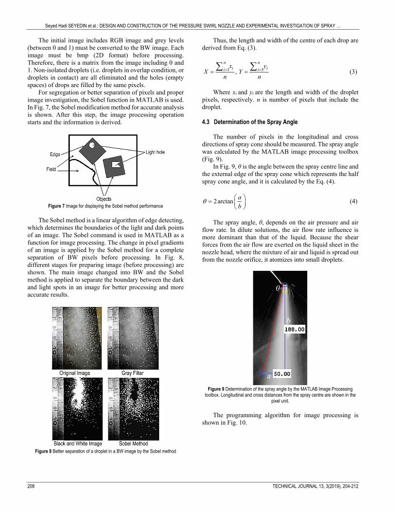
For segregation or better separation of pixels and proper image investigation, the Sobel function in MATLAB is used. In Fig. 7, the Sobel modification method for accurate analysis is shown. After this step, the image processing operation starts and the information is derived.
Figure 7 Image for displaying the Sobel method performance
The Sobel method is a linear algorithm of edge detecting,
which determines the boundaries of the light and dark points of an image. The Sobel command is used in MATLAB as a function for image processing. The change in pixel gradients of an image is applied by the Sobel method for a complete separation of BW pixels before processing. In Fig. 8, different stages for preparing image (before processing) are shown. The main image changed into BW and the Sobel method is applied to separate the boundary between the dark and light spots in an image for better processing and more accurate results.
Figure 8 Better separation of a droplet in a BW image by the Sobel method
Thus, the length and width of the centre of each drop are derived from Eq. (3).
1 1, n n
i ii ix y
X Yn n= == =
∑ ∑ (3)
Where xi and yi are the length and width of the droplet
pixels, respectively. n is number of pixels that include the droplet. 4.3 Determination of the Spray Angle
The number of pixels in the longitudinal and cross
directions of spray cone should be measured. The spray angle was calculated by the MATLAB image processing toolbox (Fig. 9).
In Fig. 9, θ is the angle between the spray centre line and the external edge of the spray cone which represents the half spray cone angle, and it is calculated by the Eq. (4).
2arctan ab
θ =
(4)
The spray angle, θ, depends on the air pressure and air
flow rate. In dilute solutions, the air flow rate influence is more dominant than that of the liquid. Because the shear forces from the air flow are exerted on the liquid sheet in the nozzle head, where the mixture of air and liquid is spread out from the nozzle orifice, it atomizes into small droplets.
Figure 9 Determination of the spray angle by the MATLAB Image Processing
toolbox. Longitudinal and cross distances from the spray centre are shown in the pixel unit.
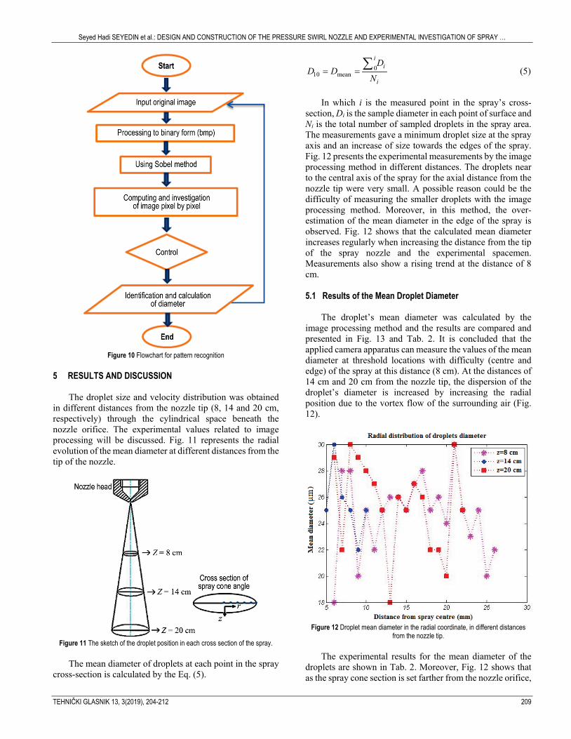
The programming algorithm for image processing is
shown in Fig. 10.
Seyed Hadi SEYEDIN et al.: DESIGN AND CONSTRUCTION OF THE PRESSURE SWIRL NOZZLE AND EXPERIMENTAL INVESTIGATION OF SPRAY …
TEHNIČKI GLASNIK 13, 3(2019), 204-212 209
Figure 10 Flowchart for pattern recognition
5 RESULTS AND DISCUSSION
The droplet size and velocity distribution was obtained in different distances from the nozzle tip (8, 14 and 20 cm, respectively) through the cylindrical space beneath the nozzle orifice. The experimental values related to image processing will be discussed. Fig. 11 represents the radial evolution of the mean diameter at different distances from the tip of the nozzle.
Figure 11 The sketch of the droplet position in each cross section of the spray.
The mean diameter of droplets at each point in the spray
cross-section is calculated by the Eq. (5).
010 mean
ii
i
DD D
N= =
∑ (5)
In which i is the measured point in the spray’s cross-
section, Di is the sample diameter in each point of surface and Ni is the total number of sampled droplets in the spray area. The measurements gave a minimum droplet size at the spray axis and an increase of size towards the edges of the spray. Fig. 12 presents the experimental measurements by the image processing method in different distances. The droplets near to the central axis of the spray for the axial distance from the nozzle tip were very small. A possible reason could be the difficulty of measuring the smaller droplets with the image processing method. Moreover, in this method, the over-estimation of the mean diameter in the edge of the spray is observed. Fig. 12 shows that the calculated mean diameter increases regularly when increasing the distance from the tip of the spray nozzle and the experimental spacemen. Measurements also show a rising trend at the distance of 8 cm.
5.1 Results of the Mean Droplet Diameter
The droplet’s mean diameter was calculated by the
image processing method and the results are compared and presented in Fig. 13 and Tab. 2. It is concluded that the applied camera apparatus can measure the values of the mean diameter at threshold locations with difficulty (centre and edge) of the spray at this distance (8 cm). At the distances of 14 cm and 20 cm from the nozzle tip, the dispersion of the droplet’s diameter is increased by increasing the radial position due to the vortex flow of the surrounding air (Fig. 12).
Figure 12 Droplet mean diameter in the radial coordinate, in different distances
from the nozzle tip. The experimental results for the mean diameter of the
droplets are shown in Tab. 2. Moreover, Fig. 12 shows that as the spray cone section is set farther from the nozzle orifice,
Seyed Hadi SEYEDIN et al.: DESIGN AND CONSTRUCTION OF THE PRESSURE SWIRL NOZZLE AND EXPERIMENTAL INVESTIGATION OF SPRAY …
210 TECHNICAL JOURNAL 13, 3(2019), 204-212
the droplet mean diameter has some fluctuations in the droplet size.
Table 2 The mean diameter of the droplets in different distances from the nozzle tip
Distance (cm) Mean Diameter (μm) 8 25.02 14 24.5 20 26.09
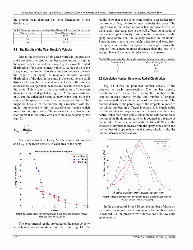
5.2 The Results of the Mean Droplet’s Velocity
Due to the existence of air-cored vortex in the pressure
swirl atomizer, the droplet number concentration is high at the region near the axis of the spray. Fig. 13 shows the radial distribution of the droplet mean velocity. At the centre of the spray cone, the droplet velocity is high and reduces towards the edge of the spray. A relatively uniform velocity distribution of droplets in the spray is observed. At the axial distance of 8 cm, the calculated mean velocity of the droplets at the centre is larger than the measured results at the edge of the spray. This is due to the over-estimation of the mean diameter which is depicted in Fig. 13. At the axial distance of 20 cm, the calculated mean velocity of the droplets at the centre of the spray is smaller than the measured results. This might be because of the uncertainty associated with the model implemented within the experimental results which may have out layer points. The mean velocity of droplets at each interval in the spray cross-section is calculated by the Eq. (6).
1Avg
Nii
vV
N==
∑ (6)
The vi is the droplet velocity, N is the number of droplets
and VAvg is the mean velocity in each area of the spray.
Figure 13 Droplet mean velocity distribution in the redial coordinate in various
distances from the nozzle tip The experimental results are based on the mean velocity
at each section and are shown in Tab. 3 and Fig. 13. The
results show that as the spray cone section is set farther from the nozzle orifice, the droplet mean velocity decreases. The liquid flow in the orifice centre is fast and near the orifice walls, and it decreases due to the wall effects. As a result of the mean droplet velocity, this velocity decreases. In the spray cone centre line, the velocity reaches the maximum. Since the spray jet is in the straight trajectory and away from the spray cone centre, the spray stream angle causes the droplets’ movement in more distances than the one of a straight line and the mean droplet velocity decreases.
Table 3 The mean velocity of the droplets in different distances from the nozzle tip
Distance (cm) Mean Velocity (m/s) 8 14.9 14 6.9 20 5.05
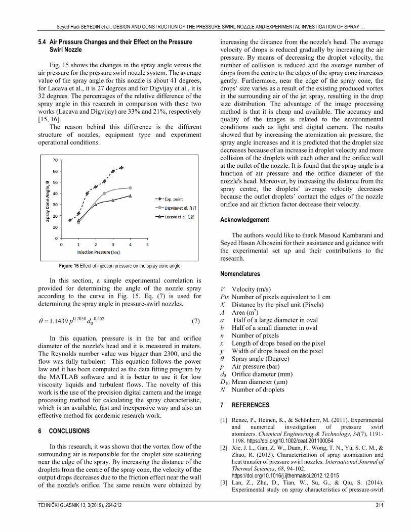
5.3 Calculation Number Density as Radial Distribution
Fig. 14 shows the predicted number density of the
droplets at each cross-section. The number density distributions are defined by dividing the number of the droplets in each interval by the total number of droplets accommodated on the circle radius of the cone section. The number density is the percentage of the droplets’ number to the whole number, in different intervals. It is considerable that the number of drops is more at the area near the spray centre, rather than other points, and is an indicator of the swirl motion of air-liquid mixture, which is counted as a feature of the nozzle. Moreover, at intervals of 14 and 20 cm, the distance of droplets increases from the spray cone centre and the number of drops reduces at that area, which is why the number density reduces as well.
Figure 14 Radial distribution of the number density at different zones of the
nozzle's output - image processing In the distances of 14 and 20 cm, the number of drops on
that surface is reduced and consequently the number density is reduced, i.e. the pressure swirl nozzle has a hollow cone spray pattern.
Seyed Hadi SEYEDIN et al.: DESIGN AND CONSTRUCTION OF THE PRESSURE SWIRL NOZZLE AND EXPERIMENTAL INVESTIGATION OF SPRAY …
TEHNIČKI GLASNIK 13, 3(2019), 204-212 211
5.4 Air Pressure Changes and their Effect on the Pressure Swirl Nozzle Fig. 15 shows the changes in the spray angle versus the
air pressure for the pressure swirl nozzle system. The average value of the spray angle for this nozzle is about 41 degrees, for Lacava et al., it is 27 degrees and for Digvijay et al., it is 32 degrees. The percentages of the relative difference of the spray angle in this research in comparison with these two works (Lacava and Digvijay) are 33% and 21%, respectively [15, 16].
The reason behind this difference is the different structure of nozzles, equipment type and experiment operational conditions.
Figure 15 Effect of injection pressure on the spray cone angle
In this section, a simple experimental correlation is
provided for determining the angle of the nozzle spray according to the curve in Fig. 15. Eq. (7) is used for determining the spray angle in pressure-swirl nozzles.
0 7058 0 452
01 1439 . .. p dθ −= (7) In this equation, pressure is in the bar and orifice
diameter of the nozzle's head and it is measured in meters. The Reynolds number value was bigger than 2300, and the flow was fully turbulent. This equation follows the power law and it has been computed as the data fitting program by the MATLAB software and it is better to use it for low viscosity liquids and turbulent flows. The novelty of this work is the use of the precision digital camera and the image processing method for calculating the spray characteristic, which is an available, fast and inexpensive way and also an effective method for academic research work.
6 CONCLUSIONS
In this research, it was shown that the vortex flow of the
surrounding air is responsible for the droplet size scattering near the edge of the spray. By increasing the distance of the droplets from the centre of the spray cone, the velocity of the output drops decreases due to the friction effect near the wall of the nozzle's orifice. The same results were obtained by
increasing the distance from the nozzle's head. The average velocity of drops is reduced gradually by increasing the air pressure. By means of decreasing the droplet velocity, the number of collision is reduced and the average number of drops from the centre to the edges of the spray cone increases gently. Furthermore, near the edge of the spray cone, the drops’ size varies as a result of the existing produced vortex in the surrounding air of the jet spray, resulting in the drop size distribution. The advantage of the image processing method is that it is cheap and available. The accuracy and quality of the images is related to the environmental conditions such as light and digital camera. The results showed that by increasing the atomization air pressure, the spray angle increases and it is predicted that the droplet size decreases because of an increase in droplet velocity and more collision of the droplets with each other and the orifice wall at the outlet of the nozzle. It is found that the spray angle is a function of air pressure and the orifice diameter of the nozzle's head. Moreover, by increasing the distance from the spray centre, the droplets’ average velocity decreases because the outlet droplets’ contact the edges of the nozzle orifice and air friction factor decrease their velocity. Acknowledgement
The authors would like to thank Masoud Kambarani and
Seyed Hasan Alhoseini for their assistance and guidance with the experimental set up and their contributions to the research.
Nomenclatures V Velocity (m/s) Pix Number of pixels equivalent to 1 cm X Distance by the pixel unit (Pixels) A Area (m2) a Half of a large diameter in oval b Half of a small diameter in oval n Number of pixels x Length of drops based on the pixel y Width of drops based on the pixel θ Spray angle (Degree) p Air pressure (bar) d0 Orifice diameter (mm) D10 Mean diameter (µm) N Number of droplets 7 REFERENCES [1] Renze, P., Heinen, K., & Schönherr, M. (2011). Experimental
and numerical investigation of pressure swirl atomizers. Chemical Engineering & Technology, 34(7), 1191-1198. https://doi.org/10.1002/ceat.201100054
[2] Xie, J. L., Gan, Z. W., Duan, F., Wong, T. N., Yu, S. C. M., & Zhao, R. (2013). Characterization of spray atomization and heat transfer of pressure swirl nozzles. International Journal of Thermal Sciences, 68, 94-102. https://doi.org/10.1016/j.ijthermalsci.2012.12.015
[3] Lan, Z., Zhu, D., Tian, W., Su, G., & Qiu, S. (2014). Experimental study on spray characteristics of pressure-swirl
Seyed Hadi SEYEDIN et al.: DESIGN AND CONSTRUCTION OF THE PRESSURE SWIRL NOZZLE AND EXPERIMENTAL INVESTIGATION OF SPRAY …
212 TECHNICAL JOURNAL 13, 3(2019), 204-212
nozzles in pressurizer. Annals of Nuclear Energy, 63, 215-227. https://doi.org/10.1016/j.anucene.2013.07.048
[4] Jain, M., John, B., Iyer, K. N., & Prabhu, S. V. (2014). Characterization of the full cone pressure swirl spray nozzles for the nuclear reactor containment spray system. Nuclear Engineering and Design, 273, 131-142. https://doi.org/10.1016/j.nucengdes.2014.02.025
[5] Belhadef, A., Vallet, A., Amielh, M., & Anselmet, F. (2012). Pressure-swirl atomization: Modeling and experimental approaches. International Journal of Multiphase Flow, 39, 13-20. https://doi.org/10.1016/j.ijmultiphaseflow.2011.09.009
[6] Kim, H. H., Ogata, A., & Kim, J. H. (2009, June). High speed camera observation of electrospray. In Electrostatics Joint Conf., Boston, MA. https://doi.org/10.1016/j.jaerosci.2011.01.007
[7] Lee, E. J., Oh, S. Y., Kim, H. Y., James, S. C., & Yoon, S. S. (2010). Measuring air core characteristics of a pressure-swirl atomizer via a transparent acrylic nozzle at various Reynolds numbers. Experimental thermal and fluid science, 34(8), 1475-1483. https://doi.org/10.1016/j.expthermflusci.2010.07.010
[8] Laryea, G. N., & No, S. Y. (2004). Spray angle and breakup length of charge-injected electrostatic pressure-swirl nozzle. Journal of Electrostatics, 60(1), 37-47. https://doi.org/10.1016/j.elstat.2003.11.001
[9] Jiang, Y., Jeon, H. Y., Tian, L., & Bode, L. E. (2010). Measuring particle size distribution using LED-illumination. International Journal of Multiphase Flow, 36(3), 193-201. https://doi.org/10.1016/j.ijmultiphaseflow.2009.11.004
[10] Nonnenmacher, S. & Piesche, M. (2000). Design of hollow cone pressure swirl nozzles to atomize Newtonian fluids. Chemical Engineering Science, 55(19), 4339-4348. https://doi.org/10.1016/S0009-2509(00)00043-9
[11] Wimmer, E. & Brenn, G. (2013). Viscous flow through the swirl chamber of a pressure-swirl atomizer. International Journal of Multiphase Flow, 53, 100-113. https://doi.org/10.1016/j.ijmultiphaseflow.2013.02.003
[12] Xie, J. L., Gan, Z. W., Wong, T. N., Duan, F., Yu, S. C. M., & Wu, Y. H. (2014). Thermal effects on a pressure swirl nozzle in spray cooling. International Journal of Heat and Mass Transfer, 73, 130-140. https://doi.org/10.1016/j.ijheatmasstransfer.2014.01.077
[13] www.mathworks.com, MATLAB software Help. Version R2014b. Developed by Mathworks Co.
[14] Kulshreshtha, D. B., Dikshit, S., & Channiwala, S. A. (2011). Experimental investigations of air assisted pressure swirl atomizer. Indian Journal of Science and Technology, 4(2), 126-130. https://doi.or/10.17485/ijst/2011/v4i2/29947
[15] Sapee, S. (2015). Computational Fluid Dynamics Study on Droplet Size of Kerosene Fuel. Journal of Advanced Research in Fluid Mechanics and Thermal Sciences, 16, 1-14.
[16] Malý, M., Sapík, M., Jedelský, J., Janáčková, L., Jícha, M., Sláma, J., & Wigley, G. (2018). Internal flow characteristics in scaled pressure-swirl atomizer. In EPJ Web of Conferences, 180, p. 02059. EDP Sciences. https://doi.org/10.1051/epjconf/201818002059
[17] Garai, A., Pal, S., Mondal, S., Ghosh, S., Sen, S., & Mukhopadhyay, A. (2017). Experimental investigation of spray characteristics of kerosene and ethanol-blended kerosene using a gas turbine hybrid atomizer. Sādhanā, 42(4), 543-555. https://doi.org/10.1007/978-981-10-7449-3_9
[18] Maly, M., Jedelsky, J., Slama, J., Janackova, L., Sapík, M., Wigley, G., & Jicha, M. (2018). Internal flow and air core dynamics in Simplex and Spill-return pressure-swirl atomizers. International Journal of Heat and Mass Transfer, 123, 805-814. https://doi.org/10.1016/j.ijheatmasstransfer.2018.02.090
Authors’ contacts:
Seyed Hadi SEYEDIN Department of Chemical Engineering, Science and Research Branch, Islamic Azad University, Daneshgah Blvd, Simon Bulivar Blvd, Tehran, Iran Majid AHMADI Corresponding author Department of Mechanical Engineering, Science and Research Branch, Islamic Azad University, Daneshgah Blvd, Simon Bulivar Blvd, Tehran, Iran [email protected] Seyed Vahid SEYEDIN Department of Software Engineering, Tehran South Branch, Islamic Azad University, Azarshahr Street, North Iranshahr Street, Karimkhan-e-Zand Avenue, Tehran, Iran
Related Documents