Design and construction of the Akashi Kaikyo bridge's superstructure Autor(en): Fuchida, Masanobu / Kurino, Sumitaka / Kitagawa, Makoto Objekttyp: Article Zeitschrift: IABSE reports = Rapports AIPC = IVBH Berichte Band (Jahr): 79 (1998) Persistenter Link: http://doi.org/10.5169/seals-59832 PDF erstellt am: 07.07.2022 Nutzungsbedingungen Die ETH-Bibliothek ist Anbieterin der digitalisierten Zeitschriften. Sie besitzt keine Urheberrechte an den Inhalten der Zeitschriften. Die Rechte liegen in der Regel bei den Herausgebern. Die auf der Plattform e-periodica veröffentlichten Dokumente stehen für nicht-kommerzielle Zwecke in Lehre und Forschung sowie für die private Nutzung frei zur Verfügung. Einzelne Dateien oder Ausdrucke aus diesem Angebot können zusammen mit diesen Nutzungsbedingungen und den korrekten Herkunftsbezeichnungen weitergegeben werden. Das Veröffentlichen von Bildern in Print- und Online-Publikationen ist nur mit vorheriger Genehmigung der Rechteinhaber erlaubt. Die systematische Speicherung von Teilen des elektronischen Angebots auf anderen Servern bedarf ebenfalls des schriftlichen Einverständnisses der Rechteinhaber. Haftungsausschluss Alle Angaben erfolgen ohne Gewähr für Vollständigkeit oder Richtigkeit. Es wird keine Haftung übernommen für Schäden durch die Verwendung von Informationen aus diesem Online-Angebot oder durch das Fehlen von Informationen. Dies gilt auch für Inhalte Dritter, die über dieses Angebot zugänglich sind. Ein Dienst der ETH-Bibliothek ETH Zürich, Rämistrasse 101, 8092 Zürich, Schweiz, www.library.ethz.ch http://www.e-periodica.ch

Welcome message from author
This document is posted to help you gain knowledge. Please leave a comment to let me know what you think about it! Share it to your friends and learn new things together.
Transcript
Design and construction of the Akashi Kaikyobridge's superstructure
Autor(en): Fuchida, Masanobu / Kurino, Sumitaka / Kitagawa, Makoto
Objekttyp: Article
Zeitschrift: IABSE reports = Rapports AIPC = IVBH Berichte
Band (Jahr): 79 (1998)
Persistenter Link: http://doi.org/10.5169/seals-59832
PDF erstellt am: 07.07.2022
NutzungsbedingungenDie ETH-Bibliothek ist Anbieterin der digitalisierten Zeitschriften. Sie besitzt keine Urheberrechte anden Inhalten der Zeitschriften. Die Rechte liegen in der Regel bei den Herausgebern.Die auf der Plattform e-periodica veröffentlichten Dokumente stehen für nicht-kommerzielle Zwecke inLehre und Forschung sowie für die private Nutzung frei zur Verfügung. Einzelne Dateien oderAusdrucke aus diesem Angebot können zusammen mit diesen Nutzungsbedingungen und denkorrekten Herkunftsbezeichnungen weitergegeben werden.Das Veröffentlichen von Bildern in Print- und Online-Publikationen ist nur mit vorheriger Genehmigungder Rechteinhaber erlaubt. Die systematische Speicherung von Teilen des elektronischen Angebotsauf anderen Servern bedarf ebenfalls des schriftlichen Einverständnisses der Rechteinhaber.
HaftungsausschlussAlle Angaben erfolgen ohne Gewähr für Vollständigkeit oder Richtigkeit. Es wird keine Haftungübernommen für Schäden durch die Verwendung von Informationen aus diesem Online-Angebot oderdurch das Fehlen von Informationen. Dies gilt auch für Inhalte Dritter, die über dieses Angebotzugänglich sind.
Ein Dienst der ETH-BibliothekETH Zürich, Rämistrasse 101, 8092 Zürich, Schweiz, www.library.ethz.ch
http://www.e-periodica.ch

63
Design and Construction of the Akashi Kaikyo Bridge's Superstructure
Masanobu FUCHIDADir., First Constr. BureauHonshu-Shikoku Bridge AuthorityKobe, Japan
Sumitaka KURINOMgr, Tarumi Constr. OfficeHonshu-Shikoku Bridge AuthorityKobe, Japan
Makoto KITAGAWAGen. Mgr, Tarumi Constr. OfficeHonshu-Shikoku Bridge AuthorityKobe, Japan
Minora SHIMOMURAMgr, Tarumi Constr. OfficeHonshu-Shikoku Bridge AuthorityKobe, Japan
Summary
This paper describes some technical features of the Akashi Kaikyo Bridge's superstructure asfollows: 1 For the towers, wind resistant design was required. The towers were fabricatedand erected with high vertical accuracy. 2 For the cables, erection was done by prefabricatedstrand PS method using newly developed high-tensile strength wires. The dehumidificationsystem was newly developed to increase the life of cables. 3 For the stiffening girder, windresistant design was done using a newly built large boundary layer wind tunnel facility. 4Because of some displacement of foundations due to the Southern Hyogo Earthquake, designand fabrication of the stiffening girders had to be modified in order to adjust to the newconfiguration of the Bridge.
1. Some problems to be overcome for the superstructures
Foliowings were essential problems to be solved for the superstructures of the Bridge.1 The Akashi Kaikyo Bridge is a suspension bridge spanning an international navigationchannel that is more than 1.5 km wide and has a sea traffic of 1,400 ships a day. Then, theerection of superstructures had to be done not to interrupt the sea traffic.2 Because of its long-span and high-rise structures, the bridge is very flexible and issusceptible to wind. Then, the wind induced dynamic oscillation of the tower and thestiffening girder had to be suppressed thorough the wind resistant design.3 Some displacement of foundations occurred by the crustal movement due to the SouthernHyogo Earthquake in January 1995, when the cable erection was almost over. To the changeof the Bridge's configuration, some modifications of the design and fabrication of thestiffening girders had to be done.
64 DESIGN AND CONSTRUCTION OF THE AKASHI KAIKYO BRIDGE
2. Technical features of tower
2.1 Wind resistant design of the tower
The tower is a steel flexible tower, with the height of 287 m. From experiences so far, thetower vibrations by the wind vortex due to the wind from the transverse direction had been a
problem to be overcome, during erection. Since the primary natural frequency of the tower ofthe Bridge is half as low as that of other 1 km class Honshu Shikoku Bridges, it was fearedthat vibration would occur below the design wind velocity of 66.7 m/s, not only duringerection but also even after completion of the bridge.
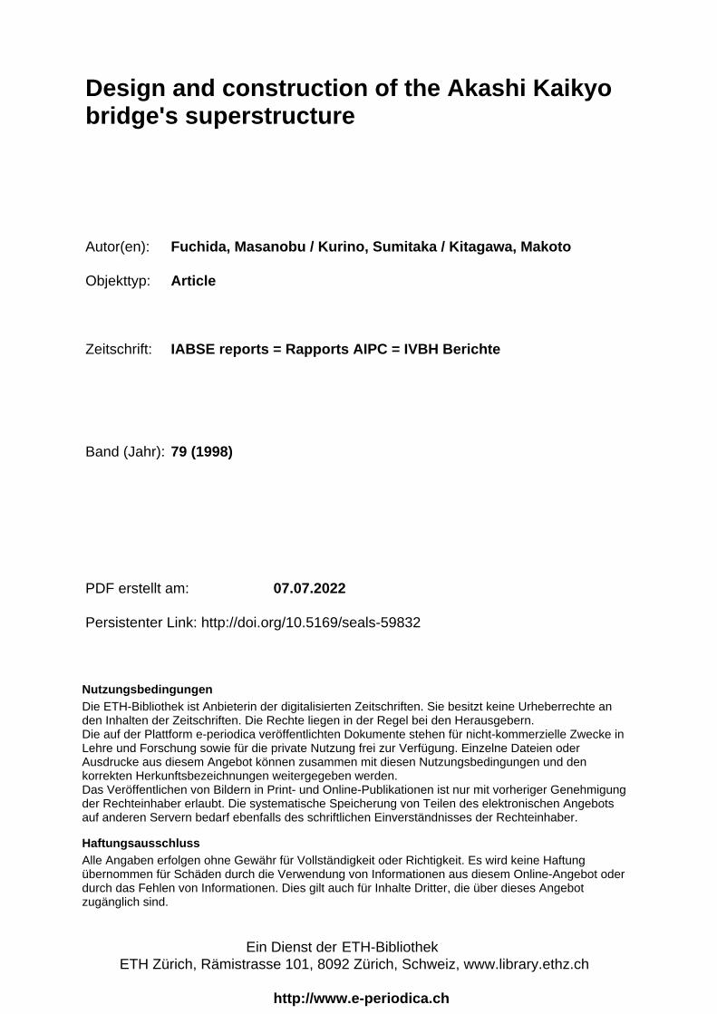
Table. 1 Comparison ofaerodynamic properties of towers
Name of Bridge Tower height 1 st bending ResonantH frequency wind speed
(m) (Hz) m/sFree standingAkashi Kaikvo 287.6 0.131 10.0
Kita Bisan Seto 169.5 0.256 16.5
CompletionAkashi Kaikyo 287.6 0.465 41.8Kita Bisan Seto 169.5 1.126 86.0
Free standing Completion
Fig. 1 Installation ofTuned Mass Damper
The vibration can be controlled either by aerodynamicimprovement of the cross section or by installing dampingdevices. For aerodynamic improvement of the cross section,fabrication of corner cut-offs in the cross section wasjudged to be most effective to suppress vortex-inducedoscillation, through several wind tunnel tests.At the same time, damping devices had to be installed tosuppress the amplitude of vortex-induced oscillation to theallowable level.The chosen damping devices were a group of tuned massdampers TMD for economical and structural reasons.TMD consists of a hanging pendulum mass, a spring andoil damper, as shown in Fig. 1. TMD-1 84 t is adamping device to suppress the vibration of the 1st bendingmode, and TMD-2 114 t is for the 1st torsional modefor the completed bridge. Both devices were installedinside of the tower shafts.
2. 2 Fabrication and erection
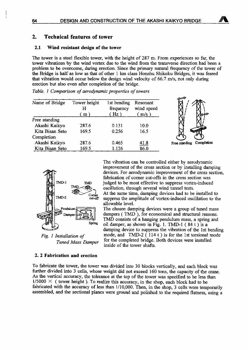
To fabricate the tower, the tower was divided into 30 blocks vertically, and each block weisfurther divided into 3 cells, whose weight did not exceed 160 tons, the capacity of the crane.As the vertical accuracy, the tolerance at the top of the tower was specified to be less than1/5000 X tower height To realize this accuracy, in the shop, each block had to befabricated with the accuracy of less than 1/10,000. Then, in the shop, 3 cells were temporarilyassembled, and the sectional planes were ground and polished to the required flatness, using a
S. KURINO, M. FUCHIDA, M. KITAGAWA, M. SHIMOMURA 65
Painting &
Inspections Grinding of Section
Fig. 2 Fabrication of towershafts
Fabrication C)Assembling Cells
Photo. 1 Erection by ClimbingTower Crane
-A f
specially madelarge-size cutting& grindingmachine.Afterward, theblocks were againseparated into 3
cells andtransported to thesite. At the site, aclimbing towercrane wasadopted tominimize theerection period.After it had laideach block, thecrane jacked itselfup to the next
level and hoisted up another one. The actual error at the top of towers was 39 mm at 2P and29 mm at 3 P.
3. Technical features of cable
3. 1 Development of high tensile strength wire
For more than 50 years, galvanized steel wire, with a diameter of 5 mm and with tensilestrength of 155-160 kg/mm", had been used for the cable of suspension bridges, due to theestablished production technology and stable quality. The size of the cable is determined bythe sag ratio and the allowable stress of wires. Using 160 kg/mm2 class wire for the Bridge,the diameter became too large, exceeding the experience of cable erections so far. So the,double cable system 2 cable/one side could not be avoided. But the double cable has
'
problems, such as increased dead load, complicated structure of the girder and long erectionperiod. To solve those problems, development of high strength galvanized steel wire wasrequired. To increase the strength of galvanized steel wire, the following three means wereconsidered.
1 Increasing the degree of processing during wire drawing2 Adding small amounts of other elements3 Controlling strength loss due to the heat reaction during galvanizing
Table. 2 Comparison ofchemical ingredientsofgalvanized wire
As a result of the investigations,low-alloy steel wire with the
C % 0.75 ~ 0.80 0.80 — 0.85Si (%) 0.12 ~ 0.32 0.80 ~ 1.00Mn % Q.60 — 0.90 0.60 ~ 0.90
160 kg/mm2 class 180 kg/mm2 classaddition of Si proved to be themost effective way to raise thetensile strength to 180 kg/mm2.The properties of the developed180 kg/mm2 class wire are
the same or better quality than the conventional wires.
3. 2 Erection of the cable
shown in Table. 2. The newlydeveloped wire showed almost
To minimize the erection period, the prefabricated parallel wire method PS method was
66 DESIGN AND CONSTRUCTION OF THE AKASHI KAIKYO BRIDGE
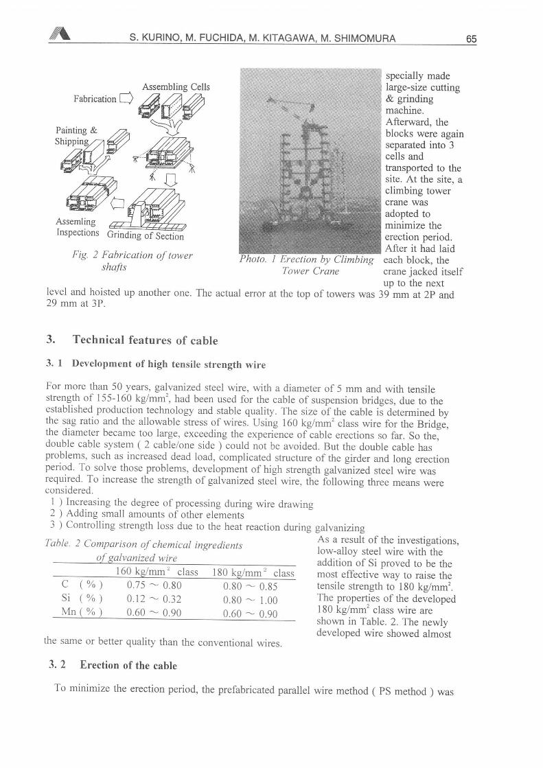
Cable 290 strands
Strand (127 wires
1.122 mm
Cross section of cable
adopted. The composition of the cable was shown in Fig. 3.
The cable erection was started by carrying a pilot rope from shore to shore. The conventional
way to carry a pilot rope is to pull a rope with floats
by a tug-boat or to pull a rope by a tall crane ship.
But these methods required sea traffic to be halted,
so it was decided to pull the rope by the helicopter,so as not to interrupt the sea traffic on theinternational navigation channel. For the helicopter,the pilot rope had to be light, strong and easy tohandle. So, a poliaramid fiber rope, with a diameter
of 10 mm, weight of 0.0917 kg/m and tensilestrength of 4700 kg, was used.The pilot ropes were connected with steel ropes, and
were pulled for the
replacement to the strongerropes. These works wererepeated, and the system tohaul cable strands werecompleted. Using this system,catwalk ropes were erectedwith floors on them. Cablestrands were erected asfollows: 1 strand reels weretransported to the yard of 1A,2 each strand was pulled bya strand carrier on a haulingsystem along the catwalk.Cable sag was measured and
adjusted during the nightwhen the temperature is stable.
To minimize the erection period two hauling systems were used for one cable.
Photo. 2 Carrying a pilot ropeby helicopter
by hauling system
3. 3 Corrosion protection method of cable
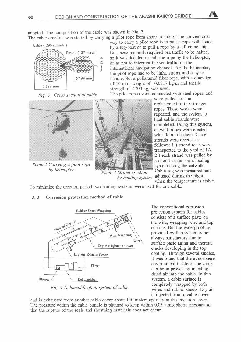
Rubber Sheet Wrapping
Fig. 4 Dehumidification system of cable
The conventional corrosionprotection system for cablesconsists of a surface paste onthe wire, wrapping wire and topcoating. But the waterproofingprovided by this system is notalways satisfactory due tosurface paste aging and thermalcracks developing in the topcoating. Through several studies,it was found that the atmosphereenvironment inside of the cablecan be improved by injectingdried air into the cable. In thissystem, a cable surface iscompletely wrapped by bothwires and rubber sheets. Dry airis injected from a cable cover
and is exhausted from another cable-cover about 140 meters apart from the injection cover.The pressure within the cable bundle is planned to keep within 0.03 atmospheric pressure sothat the rupture of the seals and sheathing materials does not occur.
S. KURINO, M. FUCHIDA, M. KITAGAWA, M. SHIMOMURA 67
4. Technical features of stiffening girder
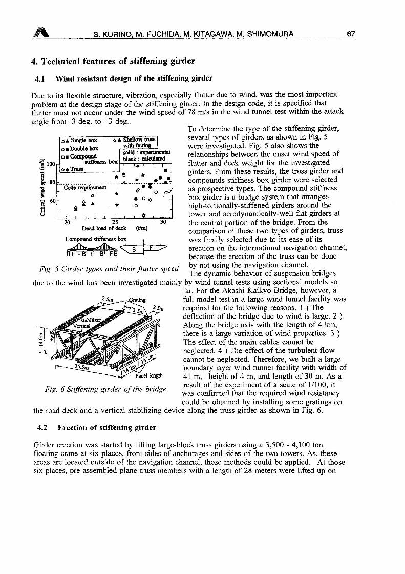
25Dead load of deck
Compound stiffeness box
(t/m)
4.1 Wind resistant design of the stiffening girder
Due to its flexible structure, vibration, especially flutter due to wind, was the most importantproblem at the design stage of the stiffening girder. In the design code, it is specified thatflutter must not occur under the wind speed of 78 m/s in the wind tunnel test within the attack
angle from -3 deg. to +3 deg..To determine the type of the stiffening girder,several types of girders as shown in Fig. 5
were investigated. Fig. 5 also shows the
relationships between the onset wind speed offlutter and deck weight for the investigatedgirders. From these results, the truss girder and
compounds stiffness box girder were selectedas prospective types. The compound stiffnessbox girder is a bridge system that arrangeshigh-tortionally-stiffened girders around thetower and aerodynamically-well flat girders atthe central portion of the bridge. From thecomparison of these two types of girders, trusswas finally selected due to its ease of itserection on the international navigation channel,because the erection of the truss can be done
by not using the navigation channel.The dynamic behavior of suspension bridges
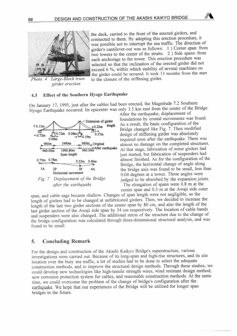
due to the wind has been investigated mainly by wind tunnel tests using sectional models sofar. For the Akashi Kaikyo Bridge, however, a
full model test in a large wind tunnel facility wasrequired for the following reasons. 1 Thedeflection of the bridge due to wind is large. 2
Along the bridge axis with the length of 4 km,there is a large variation of wind properties. 3
The effect of the main cables cannot be
neglected. 4 The effect of the turbulent flowcannot be neglected. Therefore, we built a largeboundary layer wind tunnel facility with width of41m, height of 4 m, and length of 30 m. As aresult of the experiment of a scale of 1/100, it
lS- iffenmg gir er of e ri ge was conflrmecj that the required wind resistancycould be obtained by installing some gratings on
the road deck and a vertical stabilizing device along the truss girder as shown in Fig. 6.
Fig. 5 Girder types and their flutter speed
2.5m -gating
4.2 Erection of stiffening girder
Girder erection was started by lifting large-block truss girders using a 3,500 - 4,100 tonfloating crane at six places, front sides of anchorages and sides of the two towers. As, theseareas are located outside of the navigation channel, those methods could be applied. At thosesix places, pre-assembled plane truss members with a length of 28 meters were lifted up on
68 DESIGN AND CONSTRUCTION OF THE AKASHI KAIKYO BRIDGE
Photo. 4 Large-Block trussgirder erection
the deck, carried to the front of the erected girders, and
connected to them. By adopting this erection procedure, it
was possible not to interrupt the sea traffic. The direction ofgirder's cantilever-out was as follows: 1 Center span, from
two towers to the center of the straits. 2 Side spans: from
each anchorage to the tower. This erection procedure was
selected so that the inclination of the erected girder did not
exceed 6 %, within which stability of several machines onthe girder could be secured. It took 13 months from the start
to the closure of the stiffening girder.
4.3 Effect of the Southern Hyogo Earthquake
On January 17, 1995, just after the cables had been erected, the Magnitude 7.2 Southern
Hyogo Earthquake occurred. Its epicenter was only 3.5 km east from the center of the BridgeAfter the earthquake, displacement of
10.13m
,Ti 0.72mui<-
0.09m
k_9_60mv 1990m
k -4*960.00m 1990.80m
Span length
• Extension of girder
4 0.22m
if 0.37m*0.1910
960m ^ Original
^—JAfter earthquake
0.75m 0.78m 0.52m 0.46m
2P 3P 4AHorizontal movement
Fig. 7 Displacement of the Bridge
after the earthquake
foundations by crustal movements was found.
As a result, the basic configuration of the
Bridge changed like Fig. 7. Then modified
design of stiffening girder was absolutely
required soon after the earthquake. There wasalmost no damage on the completed structures.
At that stage, fabrication of some girders had
just started, but fabrication of suspenders had
almost finished. As for the configuration of the
Bridge, the horizontal change of angle alongthe bridge axis was found to be small, less than
0.04 degrees at a tower. Those angles were
judged to be absorbed by the expansion joints.The elongation of spans were 0.8 m at the
center span and 0.3 m at the Awaji side outer
span, and cable sags became shallow. Changes of span length were not negligible, so the
length of girders had to be changed at unfabricated girders. Then, we decided to increase the
length of the last two girder sections of the center span by 80 cm, and also the length of the
last girder section of the Awaji side span by 34 cm respectively. The location of cable bands
and suspenders were also changed. The additional stress of the structure due to the change ofthe bridge configuration was calculated through three-dimensional structural analysis, and was
found to be small.
5. Concluding Remark
For the design and construction of the Akashi Kaikyo Bridge's superstructure, various
investigations were carried out. Because of its long-span and high-rise structures, and its site
location over the busy sea traffic, a lot of studies had to be done to select the adequate
construction methods, and to improve the structural design methods. Through these studies, wecould develop new technologies like high-tensile strength wires, wind resistant design method,
new corrosion protection system for cables, and reasonable construction methods. At the same
time, we could overcome the problem of the change of bridge's configuration after the
earthquake. We hope that our experiences of the Bridge will be utilized for longer span
bridges in the future.
Related Documents