DESIGN AND CONSTRUCTION OF A DEEP SOIL MIX RETAINING WALL FOR THE LAKE PARKWAY FREEWAY EXTENSION By E. W. BAHNER 1 Member, ASCE, A.M. NAGUIB 2 ABSTRACT: The extension of a new freeway in an urban area may require advanced construction methods and design to minimize land acquision, disruption to existing neighborhoods, and costs. The extension of the lake Parkway Freeway in suburban Milwaukee, Wisconsin faced all of these and many more challenges. The State of Wisconsin solicited bids for the construction on a design/build (D/B) basis to take maximum advantage of contractor innovations and to minimize schedule and costs. The construction contract was awarded to the wining team which proposed the Deep Mixing Method (DMM) of wall construction. The freeway extension is about 1000 meters long and runs through a residential area of St. Francis, Wisconsin 1000 meters west of Lake Michigan. Most of this section of the freeway will be depressed below grade in a trench about 9 meters deep. The freeway alignment also involves rerouting a railroad line, surface streets, and overhead electrical transmission lines. There are also buried high-pressure sludge lines, water lines, and other underground utilities which needed to be protected and/or avoided during construction of the freeway. In order to minimize the impact to the neighborhood, the State Department of Transportation specified that the completed wall be waterproof, minimize construction noise, and minimize schedule impacts to the railroad and electrical transmission lines. The ability to provide a flexible schedule was critical to coordinating with the utility companies and the neighborhood. The retaining wall was composed of a 12 to 18 m deep soil-cement DMM wall which was seated in clay till and low permeability glacial sediments. The DMM wall was supported with walers and permanently tied-back with earth anchors. A 610 mm thick façade of cast-in-place concrete was used as an architectural covering. At the ends of the trench, the freeway gradually returns to grade, so in these areas the wall is purely for groundwater cutoff and is not exposed. The middle one third of the wall is covered with a bridge which supports the railroad and surface street crossing. A reinforced DMM wall was used at the bridge abutments to take the full lateral loads of the excavation, and eliminate the need to design the piles of the new bridge foundations to take these loads. The construction of this structure using DMM and the D/B contracting method proved successful or the owner and contractors. By E.W. BAHNER 1 Geotechnical Engineering Manager, Woodward-Clyde International, Milwaukee, WI, USA, Email: ewbahne∅@wcc.com, Ph. 414.513.0577. AND A.M. NAGUIB 2 , Office Manager, Geo-Con Inc., Denton, TX, USA, Email: amnagui∅wcc.com Ph. 940.383.1400.

Welcome message from author
This document is posted to help you gain knowledge. Please leave a comment to let me know what you think about it! Share it to your friends and learn new things together.
Transcript

DESIGN AND CONSTRUCTION OF A DEEP SOIL MIX RETAINING WALL FOR THE LAKE PARKWAY FREEWAY EXTENSION
By E. W. BAHNER1 Member, ASCE, A.M. NAGUIB2
ABSTRACT: The extension of a new freeway in an urban area may require advanced construction methods and design to minimize land acquision, disruption to existing neighborhoods, and costs. The extension of the lake Parkway Freeway in suburban Milwaukee, Wisconsin faced all of these and many more challenges. The State of Wisconsin solicited bids for the construction on a design/build (D/B) basis to take maximum advantage of contractor innovations and to minimize schedule and costs. The construction contract was awarded to the wining team which proposed the Deep Mixing Method (DMM) of wall construction. The freeway extension is about 1000 meters long and runs through a residential area of St. Francis, Wisconsin 1000 meters west of Lake Michigan. Most of this section of the freeway will be depressed below grade in a trench about 9 meters deep. The freeway alignment also involves rerouting a railroad line, surface streets, and overhead electrical transmission lines. There are also buried high-pressure sludge lines, water lines, and other underground utilities which needed to be protected and/or avoided during construction of the freeway. In order to minimize the impact to the neighborhood, the State Department of Transportation specified that the completed wall be waterproof, minimize construction noise, and minimize schedule impacts to the railroad and electrical transmission lines. The ability to provide a flexible schedule was critical to coordinating with the utility companies and the neighborhood. The retaining wall was composed of a 12 to 18 m deep soil-cement DMM wall which was seated in clay till and low permeability glacial sediments. The DMM wall was supported with walers and permanently tied-back with earth anchors. A 610 mm thick façade of cast-in-place concrete was used as an architectural covering. At the ends of the trench, the freeway gradually returns to grade, so in these areas the wall is purely for groundwater cutoff and is not exposed. The middle one third of the wall is covered with a bridge which supports the railroad and surface street crossing. A reinforced DMM wall was used at the bridge abutments to take the full lateral loads of the excavation, and eliminate the need to design the piles of the new bridge foundations to take these loads. The construction of this structure using DMM and the D/B contracting method proved successful or the owner and contractors.
By E.W. BAHNER1Geotechnical Engineering Manager, Woodward-Clyde International, Milwaukee, WI, USA, Email: ewbahne∅ @wcc.com, Ph. 414.513.0577. AND A.M. NAGUIB2, Office Manager, Geo-Con Inc., Denton, TX, USA, Email: amnagui∅ wcc.com Ph. 940.383.1400.

INTRODUCTION The Lake Parkway Freeway is an extension of Interstate 794 designed to connect the Hoan Bridge to Layton Avenue north of General Mitchell International Airport. Where this freeway passes through the city of St. Francis, the Wisconsin Department of Transportation (WDOT) initially proposed to construct an elevated freeway. However, public outcry in the city of St. Francis, especially over the potential division of the city by the bridge forced WDOT and their consultant to consider other options including a tunnel and depressed roadway section. A depressed roadway was ultimately selected as the more cost-effective of the two alternatives. To construct the depressed roadway, WDOT decided on the design/build (D/B) approach to take advantage of contractor innovation, and minimize both schedule and cost. The D/B team of Schnabel Foundation Company, Geo-Con, Inc., and Woodward-Clyde International proposed a permanently tiedback deep mixing method (DMM) wall, the approach that was ultimately deemed the quickest and most cost-effective method. An example section of the DMM wall is shown in Figure 1. The anchors and wales are not shown for clarity. This project represented the first time that this innovative earth retention method was used in the upper Midwest. The construction of the DMM wall was completed 1 month ahead of schedule and below budget. PROJECT DESCRIPTION The project consisted of approximately 912 meters of depressed roadway beginning at East Elizabeth Avenue on the south end of the alignment, and ending approximately 305 meters north of East Morgan Avenue. The alignment is positioned in a railway/utility corridor hat runs through a residential area of St. Francis, and is approximately 1000 meters west of Lake Michigan (Figure 2). Construction of this portion of the Lake Parkway alignment required the rerouting of an existing rail line, an existing street, and an overhead high voltage electrical line. Since the depressed roadway would be as much as 9 meters below grade, buried high-pressure sludge, sewer, and water lines were also of major concern. One of these lines was a 2100 mm water line that carries most of the City of Milwaukee’s drinking water. Such utilities pass below the roadway parallel or perpendicular to the alignment. These utilities required special consideration during construction by either avoiding them if they crossed below the lowest points of the cutoff walls, or grouting around them to cut off potential leakage paths where they passed through the cutoff walls. SUBSURFACE CONDITIONS The soil borings drilled for the subject alignment revealed a highly layered profile of fill, clay, silt, and sand underlain by very stiff clay till. These glacial sediments show no definite pattern of layering. The clay till below the sediments is highly over consolidated, and is present within 6 to 12 meters in of the ground surface
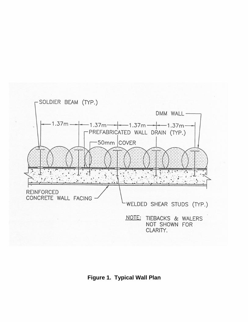
Figure 1. Typical Wall Plan

Figure 2. Vicinity Map
on the south end of the alignment, and as deep as 15 to 18 meters on the north end of the alignment. Limestone bedrock is present at a depth of 30 meters or more below the existing grade. Groundwater was measured at depths of 0.6 to 3.7 meters in deep and shallow wells along the alignment as part of the original geotechnical investigation. Shallower perched water was also anticipated in area with sand and silt layers. CUTOFF WALL DESIGN/DESIGN CRITERIA The design and construction of the DMM cutoff wall was the responsibility of Geo-Con and Woodward-Clyde, while the tiebacks and facing walls were designed by Schnabel Foundation Company. The design/build documents prepared by the WDOT identified the following criteria for the cutoff wall/retention system design: • Minimum design life of 75 years
• A maximum groundwater infiltration rate of 6200 liters/day per meter (500 gpd/lf) • A maximum groundwater table drop of 152 mm at a distance of 15 meters behind the cutoff walls. • Maximum lateral wall movements not exceeding 25 mm. • A minimum facing wall thickness of 610mm at the base of the wall.
Driven sheeting was deemed an unacceptable scheme due to the potential for leakage through the interlocks, and between sheets driven out of interlock. DMM WALL DESIGN The geology of the site consists of highly layered deposits of sand, silt, silty clay, and clayey silt. These layered deposits are underlain by very stiff clay till which gradually slopes down to the north. To effectively create a cutoff around the perimeter of the depressed roadway section, a combination of DMM structural walls and non-structural cutoff walls were built. The termination depths of the cutoff walls were determined using the finite element program SEEP/W and hand calculations. A wall permeability of 1 x 10⁻⁹ to 1 x 10⁻⁷ m/s was assumed in the analyses. These analyses indicated that the design criteria identified above could be met by either keying the cutoff walls into the underlying very stiff clay till

layer, or where the depth to the till layer was greater, penetrating intermediate layers of stiff clay, silt and clayey silt. In many cases, the thickness of these layers was substantial. The results of the SEEP/W analyses generally resulted in expected groundwater inflows of 2.48 to 30 lpd/m (0.2 to 2.4 gpd/lf), and drawdowns on the order of 25 mm for wall permeabilities of 10-9 to 10-8 m/s. These inflow rates increased to 62 to 186 lpd/m (5 to 15 gallons gpd/lf) and drawdowns of 76 to 229 mm when a wall permeability of 10-7 m/s was assumed. Accordingly, it was decided to key the cutoff walls into the till layer south of St. Francis Avenue where it was relatively shallow, and penetrate the shallower low permeability sediments with cutoff walls constructed north of St. Francis Avenue. JET GROUT CUTOFFS Jet grouting was used as the sole means of groundwater cutoff around underground utilities. The diameter of these utilities ranged from 300 to 3100 mm. The cutoffs were created by drilling vertical and angled holes to create soil-cement collars around the subject utilities that were of equivalent strength and permeability to the adjacent DSM wall. Where necessary, potential flow paths below the soil-cement collar and along the line of the pipes were lengthened by extending the collar laterally along the pipe behind the plane of the DMM wall. CONSTRUCTION PROCEDURES The structural wall was constructed in two main steps. The first step consisted of drilling and in-situ mixing of the soils with cement-bentonite grout. This was followed by installation of steel soldier beams on 1.37 meter centers within the freshly mixed (i.e. prior to curing) columns. The grout was produced on-site using two high-shear lightning batch plants. Bentonite slurry was prepared by mixing dry bentonite with water. The slurry was pre-hydrated in the first batch plant, and was then pumped to a second plant for cement addition and conveyance to the soil-mixing rig. Each batch plant was equipped with a silo for dry storage and delivery (See Figure 3). The silos were mounted over each batch plant. Rotary vane feeders were installed at the bottom of each silo to facilitate ingredient metering and delivery to each plant in accordance with a predetermined cement-bentonite design mix. Upon grout preparation, the cement-bentonite mixture was conveyed to the soil-mixing rig. The Deep Mixing system consists of a 136 metric ton crane supporting a set of leads that guides four, 0.9 m diameter mixing shafts/augers (Figure 4). As the shafts/augers were advanced vertically into the in-situ soils, the cement-bentonite grout was injected through the hollow stems of the mixing shafts and discharged at the auger heads. By combining auger flights and
Figure 3. Schematic Batch Plant

Figure 4. Schematic of Four Shaft DMM Rig

Figure 5. DMM Column Overlap Pattern

mixing paddles along the shafts, the soil is lifted and blended with the grout in a pugmill-like fashion. Once the wall design depth was reached, the mixing shaft rotation was reversed and the mixing process was repeated as the shafts were retracted, leaving homogeneously mixed soilcrete columns. Wall continuity was assured in two ways: First, by the overlapping configuration of the auger flights and mixing blades of adjacent shafts. Second, by the overlap created between previously constructed columns and new columns (See Figure 5). Furthermore, the grout mixture was injected as the augers were advanced allow mixing during advancement and retraction of the augers. After mixing, the steel soldier beams were set in the freshly mixed columns using a small vibratory hammer mounted on a 91 metric ton crane. The beams were lowered through steel templates that were surveyed in-place and anchored over the freshly mixed columns. The templates were used to assure that the specified spacing between the soldier beams was maintained, and that the plumbness/verticality of the beams was consistent with the specified tolerances. The templates were aligned with an established project baseline. The required alignment tolerance specified in the project drawings were as follows: • Plumbness: +1%
• Horizontal Tolerance of Top Location: + 50 mm.
Overall, the soldier beams were readily installed within these criteria. Beams installed outside of these tolerances were removed and re-driven with a vibratory hammer when the mix was still plastic. Other work associated with the DMM retaining wall consisted of installation of tieback anchors, wales, and a cast-in-place concrete facing by Schnabel Foundation Company. This was done upon DMM wall during and mass soil excavation along the faces of the walls. CONSTRUCTION MONITORING The Deep Soil Mixed wall was monitored during construction to ensure that the specified design parameters were achieved. this consisted of obtaining “wet”, remolded soilcrete samples for permeability and unconfined compressive strength testing. The samples were obtained at various locations and depths along the DMM wall alignment. Permeability testing was performed on collected samples after a 14-day cure time. Unconfined compressive strength was performed on collected samples after 3, 7, 14, and 28 days of curing. The design unconfined compressive strength of the wall was 0.5 MPa. The results of three-day tests completed on the test cylinders were typically 2 to 4 times the design strength. Hydraulic conductivity was measured in the laboratory using flexible wall permeability tests, and measurements typically ranged form 1 x 10⁻⁸ and 9 x
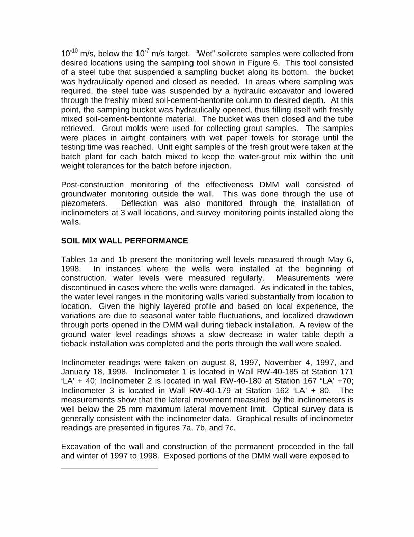
10-10 m/s, below the 10-7 m/s target. “Wet” soilcrete samples were collected from desired locations using the sampling tool shown in Figure 6. This tool consisted of a steel tube that suspended a sampling bucket along its bottom. the bucket was hydraulically opened and closed as needed. In areas where sampling was required, the steel tube was suspended by a hydraulic excavator and lowered through the freshly mixed soil-cement-bentonite column to desired depth. At this point, the sampling bucket was hydraulically opened, thus filling itself with freshly mixed soil-cement-bentonite material. The bucket was then closed and the tube retrieved. Grout molds were used for collecting grout samples. The samples were places in airtight containers with wet paper towels for storage until the testing time was reached. Unit eight samples of the fresh grout were taken at the batch plant for each batch mixed to keep the water-grout mix within the unit weight tolerances for the batch before injection. Post-construction monitoring of the effectiveness DMM wall consisted of groundwater monitoring outside the wall. This was done through the use of piezometers. Deflection was also monitored through the installation of inclinometers at 3 wall locations, and survey monitoring points installed along the walls. SOIL MIX WALL PERFORMANCE Tables 1a and 1b present the monitoring well levels measured through May 6, 1998. In instances where the wells were installed at the beginning of construction, water levels were measured regularly. Measurements were discontinued in cases where the wells were damaged. As indicated in the tables, the water level ranges in the monitoring walls varied substantially from location to location. Given the highly layered profile and based on local experience, the variations are due to seasonal water table fluctuations, and localized drawdown through ports opened in the DMM wall during tieback installation. A review of the ground water level readings shows a slow decrease in water table depth a tieback installation was completed and the ports through the wall were sealed. Inclinometer readings were taken on august 8, 1997, November 4, 1997, and January 18, 1998. Inclinometer 1 is located in Wall RW-40-185 at Station 171 ‘LA’ + 40; Inclinometer 2 is located in wall RW-40-180 at Station 167 “LA’ +70; Inclinometer 3 is located in Wall RW-40-179 at Station 162 ‘LA’ + 80. The measurements show that the lateral movement measured by the inclinometers is well below the 25 mm maximum lateral movement limit. Optical survey data is generally consistent with the inclinometer data. Graphical results of inclinometer readings are presented in figures 7a, 7b, and 7c. Excavation of the wall and construction of the permanent proceeded in the fall and winter of 1997 to 1998. Exposed portions of the DMM wall were exposed to
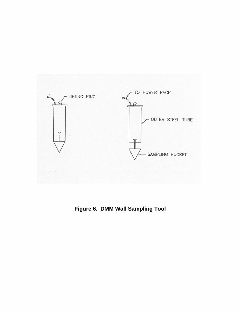
Figure 6. DMM Wall Sampling Tool

repeated freezing and thawing, attributed to the unusually mild Wisconsin winter. At such, frost expansion and associated surficial crumbling of the exposed DMM wall was observed in areas. However, this phenomenon was considerably less pronounced where the walls were protected. At one bridge abutment location where deterioration was the most pronounced, a protective shotcrete layer was placed in advance of bridge abutment pile driving. CONCLUSIONS The lake Parkway project provides an excellent example of the DMM earth retention technique. The approach resulted in the construction of a structurally sound, watertight and aesthetically pleasing finished wall. DMM provided a notable cost savings over comparable diaphragm wall systems, and resulted in a shorter construction time schedule. ACKNOWLEDGMENTS The authors respectfully acknowledge D/B team member Schnabel Foundation Company and their professionalism on this interesting and challenging project. The design support provided by Mr. Richard Tocher and Mr. David Manka of Woodward-Clyde Denver, and the exceptional efforts of field engineer Mr. Jeremy Craven of Woodward-Clyde Milwaukee and DSM specialist Mr. John Thall of Geo-Con are also acknowledged.

Table 1a Lake Parkway – Groundwater Level Monitoring
Wells South of St. Francis Avenue
Date Water Level MW-1 MW-1R MW-2 MW-2R MW-3 MW-3R MW-4 MW-5 MW-6
4/17/97 Dry 8.93 7.00 8.55 9.39 12.98 4/23/97 Dry 9.07 6.87 8.72 9.62 13.32 5/7/97 16.79 8.12 5.68 8.90 9.56 14.00 5/15/97 16.90 8.40 6.43 9.54 5/22/97 16.90 7.02 8.98 10.32 14.53 6/3/97 16.91 6.68 9.17 10.54 6/13/97 16.91 7.21 9.34 10.54 14.93 6/20/97 16.46 5.80 9.13 10.05 14.12 6/30/97 13.11 3.90 8.32 9.85 13.24 7/3/97 11.00 4.07 7.76 9.17 11.12 7/30/97 13.19 6.76 8.74 10.33 14.28 8/5/97 13.56 7.27 8.89 10.42 14.51 11/25/97 12.48 6.50 11.11 10.60 11.94 16.04 12/10/97 12.16 5.94 10.80 10.70 11.92 16.06 2/2/98 11.95 3.63 9.04 10.49 14.95 2/5/98 11.98 3.95 9.12 10.30 14.71 4/27/98 11.50 3.94 8.45 9.88 13.62 5/6/98 11.57 3.99 8.57 8.72 9.93 13.69 Notes: 1. Monitoring Wells MW-1 and MW-3 were installed in Spring, 1997 and were knocked out by ditch grade operations during Fall, 1997. 2. Monitoring Wells MW-2 was installed in Spring, 1997 and was knocked out about 1 month later by excavators. 3. Monitoring wells MW-1, MW-2 and MW-3 were replaced by MW-1R, MW-2R, and MW-3R in Fall 1997.

Table 1b Lake Parkway – Groundwater Level Monitoring
Wells North of St. Francis Avenue
Date Water Levels MW-7 MW-7R MW-9 MW-10 MW-11 MW-12 MW-13 Range 0.00 2.97 5.67 9.77 5.40 2.49 6.53 4/17/97 4/23/97 5/7/97 5/15/97 5/22/97 Dry 19.55 6/3/97 Dry 6/13/97 Dry 11.92 20.58 6/20/97 Dry 6/30/97 Dry 7.50 17.15 7/3/97 25.45 7.43 16.42 7/30/97 10.77 17.89 8/5/97 11.17 18.53 11/25/97 23.08 13.00 23.80 20.93 9.46 9.22 12/10/97 23.32 13.10 24.10 21.08 9.36 9.38 2/2/98 23.21 11.47 23.48 19.91 8.29 15.14 2/5/98 23.08 10.74 23.32 19.38 8.08 14.22 4/27/98 20.53 9.49 14.33 15.68 6.97 15.66 5/6/98 20.35 9.83 15.10 15.88 7.03 15.75 Notes: 1. MW-7 was installed Spring, 1997 and knocked out late Summer, 1997. 2. MW-7 was replaced by MW-7R. 3. MW-8 was not installed due to lack of access.


Related Documents