Design and Analysis of Trusted Computing Platforms Dries SCHELLEKENS Jury: Prof. dr. ir. Hugo Hens, chair Prof. dr. ir. Bart Preneel, supervisor Prof. dr. ir. Frank Piessens Prof. dr. ir. Joos Vandewalle Prof. dr. ir. Ingrid Verbauwhede Prof. dr. techn. Dieter Gollmann (Technische Universität Hamburg-Harburg) Prof. dr.-ing. Ahmad-Reza Sadeghi (Technische Universität Darmstadt) Dissertation presented in partial fulfillment of the requirements for the degree of Doctor in Engineering December 2012

Welcome message from author
This document is posted to help you gain knowledge. Please leave a comment to let me know what you think about it! Share it to your friends and learn new things together.
Transcript

Design and Analysis of Trusted Computing Platforms
Dries SCHELLEKENS
Jury:Prof. dr. ir. Hugo Hens, chairProf. dr. ir. Bart Preneel, supervisorProf. dr. ir. Frank PiessensProf. dr. ir. Joos VandewalleProf. dr. ir. Ingrid VerbauwhedeProf. dr. techn. Dieter Gollmann(Technische Universität Hamburg-Harburg)
Prof. dr.-ing. Ahmad-Reza Sadeghi(Technische Universität Darmstadt)
Dissertation presented in partialfulfillment of the requirements forthe degree of Doctorin Engineering
December 2012

© Katholieke Universiteit Leuven – Faculty of Engineering ScienceKasteelpark Arenberg 10, B-3001 Heverlee (Belgium)
Alle rechten voorbehouden. Niets uit deze uitgave mag worden vermenigvuldigden/of openbaar gemaakt worden door middel van druk, fotocopie, microfilm,elektronisch of op welke andere wijze ook zonder voorafgaande schriftelijketoestemming van de uitgever.
All rights reserved. No part of the publication may be reproduced in any formby print, photoprint, microfilm or any other means without written permissionfrom the publisher.
D/2013/7515/4ISBN 978-94-6018-617-2

Acknowledgements
I would like to take this opportunity to thank everyone who has supported meduring my journey towards this thesis.
First and foremost, I would like to express my gratitude to my promotorProf. Bart Preneel for giving me the opportunity to do research and pursue aPh.D. at COSIC, for his guidance and advice, and for carefully reading andcorrecting this dissertation. I wish to thank Prof. Frank Piessens, Prof. JoosVandewalle, Prof. Ingrid Verbauwhede, Prof. Dieter Gollmann and Prof. Ahmad-Reza Sadeghi for being members of my jury and Prof. Hugo Hens for chairingit.
I am indebted to my co-authors and the many people I worked with in differentprojects. In particular I am grateful to Klaus Kursawe and Pim Tulys for theclose collaboration during their days at COSIC.
COSIC has been a stimulating working environment and many of my colleaguesbecame friends. Hence, I would like to thank the past and current COSICmembers, including An, András, Andreas, Anthony, Antoon, Bartek, Benedikt,Berna, Christophe, Christopher, Claudia, Danny, Dave, Elke, Elmar, Fré,Filipe, Jasper, Jens, Joe, Joris, Junfeng, Gauthier, George, Gregory, Kazuo,Klaus, Koen, Markulf, Markus, Miroslav, Nele, Nessim, Norbert, Orr, Robert,Roel, Roel, Pim, Saartje, Sebastian, Sebastiaan, Stefaan, Stefan, Svetla, Taizo,Thomas, Yoni, and Wim. In particular, I would like to thank Brecht Wyseur,Jan Cappaert, Karel Wouters and Yoni De Mulder for sharing different officesin the ESAT building.
A special thank you also goes to Péla Noë for being the best secretary in theworld and much more and for sharing my passion for dogs.
Ik wil ook graag mijn familie en vrienden bedanken voor hun onvoorwaardelijkesteun. De laatste maar belangrijkste persoon die ik wil bedanken, is mijnvriendin Sofie voor haar liefde, geduld en steun, en voor de tijd die ze mij
i

ii ACKNOWLEDGEMENTS
gegund heeft om deze thesis te voltooien. Bedankt voor alles!
Dries SchellekensDecember 2012

Abstract
This thesis deals with the analysis and design of trusted computing platforms.Trusted computing technology is a relatively new enabling technology to improvethe trustworthiness of computing platforms. With minor changes to the bootprocess and the addition of a new hardware security component, called TPM(Trusted Platform Module), trusted computing platforms offer the possibilityto verifiably report their integrity to external parties (i.e., remote attestation)and to bind information to a specific platform (i.e., sealed storage).
The first part of this thesis mainly focuses on the analysis of existing trustedcomputing platforms. We analyze the functionality provided by the specificationsof the TCG (Trusted Computing Group) and purely software-based alternatives.Based on this analysis we present an improvement to a software-based attestationscheme: we propose to measure the execution time of a memory checksumfunction locally (with the time stamping functionality of the TPM) instead ofremotely (over the network).
We also study the resilience of trusted computing platforms against hardwareattacks. We describe how attacks on the communication interface of the TPMcan circumvent the measured boot process. The feasibility of these attacks isinvestigated in practice. Additionally we explore which operations should betargeted with a side channel attack to extracts the secret keys of a TPM.
The second part of this thesis addresses some of the challenges to implementtrusted computing technology on embedded and reconfigurable devices. One ofthe main problems when integrating a TPM into a system-on-chip design, isthe lack of on-chip reprogrammable non-volatile memory. We develop schemesto securely externalize the non-volatile storage of a TPM. One scheme reliesa new security primitive, called a reconfigurable physical unclonable function,and another extends the security perimeter of the TPM to the external memorywith a cryptographic protocol.
We propose a new architecture to reset the trust boundary to a much smaller
iii

iv ABSTRACT
scale, thus allowing for simpler and more flexible TPM implementations. Thearchitecture has two distinctive features: the program code is stored outsidethe coprocessor and only gets loaded in RAM memory when needed, and thearchitecture is open by allowing to execute arbitrary programs in remotelyverifiable manner.
Finally, we study how the TPM can be implemented securely on reconfigurablehardware. This type of implementation is beneficial because it allows forupdates of the software as well as of the hardware of the TPM (e.g., thecryptographic coprocessor) in the field. We examine the implementation optionson reconfigurable hardware that is currently available commercially. Next,we propose a novel architecture that can measure and report the integrity ofconfiguration bitstreams.

Samenvatting
Dit proefschrift handelt over de analyse en het ontwerp van vertrouwdecomputerplatformen. Vertrouwde computerplatformen zijn een relatief nieuwetechnologie die de betrouwbaarheid van computersystemen kan verbeteren.Door kleine wijzigingen aan het opstartproces en de toevoeging van een nieuwehardwarebeveiligingscomponent, TPM (Trusted Platform Module) genoemd,maken vertrouwde computerplatformen het mogelijk om hun integriteit opeen verifieerbare manier te rapporteren aan externe partijen (dit is attestatieop afstand) en om informatie te koppelen aan een specifiek platform (dit isverzegelde opslag).
Het eerste deel van dit proefschrift concentreert zich voornamelijk op de analysevan bestaande vertrouwde computersystemen. We bekijken de functionaliteitdie aangeboden wordt door de specificaties van de TCG (Trusted ComputingGroup) en door puur software-gebaseerde alternatieven. Op basis van dezeanalyse stellen we een verbetering voor aan een schema voor software-gebaseerde attestatie. Hierbij wordt de uitvoeringstijd van de functie dieeen checksum over het geheugen berekent, lokaal gemeten (met behulp van detijdszegelfunctionaliteit van de TPM) in plaats van de meting op afstand (overhet netwerk) uit te voeren.
We bestuderen ook in welke mate vertrouwde computerplatformen beschermingbieden tegen hardware-aanvallen. We beschrijven hoe aanvallen op decommunicatie-interface van de TPM het geauthentiseerde opstartproces kunnenomzeilen. De praktische haalbaarheid van deze aanvallen wordt onderzocht.Bovendien onderzoeken we op welke bewerkingen nevenkanaalaanvallen zichmoeten richten om de geheime sleutels van een TPM te achterhalen.
Het tweede deel van dit proefschrift pakt enkele uitdagingen aan die zich stellenwanneer de technologie van vertrouwde computerplatformen toegepast wordtop ingebedde en herconfigureerbare toestellen. Een van de pijnpunten van deintegratie van een TPM in een systeem-op-chip-ontwerp, is het feit dat intern
v

vi SAMENVATTING
niet-vluchtig geheugen onvoldoende voor handen is. We ontwerpen schema’som de niet-vluchtige opslag van een TPM op een beveiligde manier externte maken. Eén schema steunt op een nieuw beveiligingsprimitief, dat eenherconfigureerbare fysisch onkloonbare functie genoemd wordt. Een andereoplossing breidt de beveiligingsperimeter van de TPM uit naar het externgeheugen met een cryptografisch protocol.
We stellen een nieuwe architectuur voor die de vertrouwensgrens terugzet naareen veel kleinere schaal en die aldus meer eenvoudige en meer flexibele TPM-implementaties toelaat. De architectuur heeft twee onderscheidende kenmerken:de programmacode wordt buiten de coprocessor opgeslagen en enkel in het RAM-geheugen geladen wanneer nodig en de architectuur is open door de uitvoeringvan willekeurige programma’s toe te laten zodat dit op afstand geverifieerd kanworden.
Ten slotte bestuderen we hoe de TPMs op veilige wijze geïmplementeerdkunnen worden op herconfigureerbare hardware. Zo’n implementatie is voordeligomdat het toelaat om zowel de software als hardware van de TPM (bv. decryptografische coprocessor) bij te werken. We onderzoeken de mogelijkhedentot implementatie op herconfigureerbare hardware die momenteel commercieelbeschikbaar is. Daarna stellen we een nieuwe architectuur voor die de integriteitvan configuratiebestanden kan meten en rapporteren.

Contents
Acknowledgements i
Abstract iii
Samenvatting v
Contents vii
List of Figures xiii
List of Tables xv
List of Acronyms xvii
1 Introduction 1
1.1 Background on Trusted Computing . . . . . . . . . . . . . . . . . 1
1.1.1 Closed Platforms . . . . . . . . . . . . . . . . . . . . . . 2
1.1.2 Open Platforms . . . . . . . . . . . . . . . . . . . . . . . 2
1.1.3 Secure Coprocessor . . . . . . . . . . . . . . . . . . . . . 4
1.1.4 Trusted Computing Platforms . . . . . . . . . . . . . . . 5
1.1.5 Compatibility with Legacy Operating System . . . . . . 7
1.2 Thesis Outline and Contributions . . . . . . . . . . . . . . . . . 8
vii

viii CONTENTS
2 Remote Attestation 11
2.1 Attestation with Trusted Computing Platforms . . . . . . . . . . 11
2.1.1 Trusted Platform Module . . . . . . . . . . . . . . . . . 12
2.1.2 TCG Functionality . . . . . . . . . . . . . . . . . . . . . 15
2.1.3 Application Level Attestation . . . . . . . . . . . . . . . 19
2.2 Software-based Attestation on Legacy Platforms . . . . . . . . . 21
2.2.1 Checksum Functions . . . . . . . . . . . . . . . . . . . . . 21
2.2.2 Pioneer . . . . . . . . . . . . . . . . . . . . . . . . . . . 22
2.2.3 Timed Executable Agent System . . . . . . . . . . . . . 25
2.3 Local Execution Time Measurement with TPMs . . . . . . . . 25
2.3.1 TPM Time Stamping . . . . . . . . . . . . . . . . . . . 26
2.3.2 Improved Pioneer Protocol . . . . . . . . . . . . . . . . 27
2.3.3 Proxy Attacks . . . . . . . . . . . . . . . . . . . . . . . 29
2.3.4 Experimental Results . . . . . . . . . . . . . . . . . . . 29
2.4 Configuration Identification with Trusted Bootloader . . . . . . 30
2.4.1 Processor Identification . . . . . . . . . . . . . . . . . . . 31
2.4.2 Runtime Checksum Performance Measurement . . . . . . 31
2.5 Conclusion . . . . . . . . . . . . . . . . . . . . . . . . . . . . . 32
3 Hardware Attacks 33
3.1 Attacks on Trusted Computing Platforms . . . . . . . . . . . . 33
3.1.1 Attacks on the TPM . . . . . . . . . . . . . . . . . . . . 34
3.1.2 Attacks on the Platform . . . . . . . . . . . . . . . . . . 36
3.2 Attacking the TPM Communication Bus . . . . . . . . . . . . . 38
3.2.1 Passive Monitoring . . . . . . . . . . . . . . . . . . . . . 39
3.2.2 Reset Attacks . . . . . . . . . . . . . . . . . . . . . . . . . 41
3.2.3 Active Monitoring . . . . . . . . . . . . . . . . . . . . . 43

CONTENTS ix
3.2.4 Transport Session . . . . . . . . . . . . . . . . . . . . . 44
3.2.5 LPC Bus Encryption . . . . . . . . . . . . . . . . . . . . 46
3.2.6 Integrated TPM . . . . . . . . . . . . . . . . . . . . . . 47
3.3 Experimental Results . . . . . . . . . . . . . . . . . . . . . . . . 50
3.3.1 Reverse Engineering of TPM Daughterboard . . . . . . 50
3.3.2 Low Pin Count Bus . . . . . . . . . . . . . . . . . . . . 53
3.3.3 Analysis of Trusted Platform Communication . . . . . . 56
3.4 Side-Channel Attacks on TPMs . . . . . . . . . . . . . . . . . . 57
3.4.1 Attacking the Endorsement Key . . . . . . . . . . . . . 58
3.4.2 Attacking the Storage Root Key . . . . . . . . . . . . . 59
3.5 Conclusion . . . . . . . . . . . . . . . . . . . . . . . . . . . . . 60
4 Non-Volatile State Protection 63
4.1 Introduction . . . . . . . . . . . . . . . . . . . . . . . . . . . . . 63
4.1.1 Mobile Trusted Module . . . . . . . . . . . . . . . . . . 64
4.1.2 Embedded Trusted Computing . . . . . . . . . . . . . . 65
4.1.3 Non-Volatile State . . . . . . . . . . . . . . . . . . . . . 67
4.1.4 Monotonic Counters . . . . . . . . . . . . . . . . . . . . 68
4.2 Protection of Non-Volatile State in External Memory . . . . . . 69
4.2.1 Security Requirements . . . . . . . . . . . . . . . . . . . 69
4.2.2 Generic Approaches . . . . . . . . . . . . . . . . . . . . 70
4.2.3 Authenticated Encryption . . . . . . . . . . . . . . . . . 72
4.2.4 Frequency of State Updates . . . . . . . . . . . . . . . . 74
4.2.5 Authentication Tree . . . . . . . . . . . . . . . . . . . . 74
4.2.6 On-Chip Non-Volatile Memory . . . . . . . . . . . . . . 79
4.3 Physical Unclonable Function-Based Key Storage . . . . . . . . 82
4.3.1 Physical Unclonable Functions . . . . . . . . . . . . . . 83

x CONTENTS
4.3.2 Reliable Key Extraction with Fuzzy Extractors . . . . . 84
4.3.3 Reconfigurable PUFs . . . . . . . . . . . . . . . . . . . . 85
4.3.4 Non-Volatile State Protection with RPUFs . . . . . . . 92
4.3.5 Discussion . . . . . . . . . . . . . . . . . . . . . . . . . . 94
4.4 Extending the Security Perimeter of the Trusted Module . . . . 97
4.4.1 Non-Volatile State Protection with External Authenti-cated NVM . . . . . . . . . . . . . . . . . . . . . . . . . 97
4.4.2 Memory Authentication Protocols . . . . . . . . . . . . 99
4.4.3 Practical Aspects . . . . . . . . . . . . . . . . . . . . . . 102
4.4.4 Alternative Segregation of Responsibilities . . . . . . . . 103
4.5 Conclusion . . . . . . . . . . . . . . . . . . . . . . . . . . . . . 104
5 Flexible TPM Architecture 107
5.1 Introduction . . . . . . . . . . . . . . . . . . . . . . . . . . . . . 107
5.1.1 Related Work . . . . . . . . . . . . . . . . . . . . . . . . 108
5.1.2 Towards an Alternative TPM Architecture . . . . . . . 110
5.2 µTPM Architecture . . . . . . . . . . . . . . . . . . . . . . . . 112
5.2.1 Design Principles . . . . . . . . . . . . . . . . . . . . . . 113
5.2.2 Process Management . . . . . . . . . . . . . . . . . . . . 118
5.2.3 Memory Management . . . . . . . . . . . . . . . . . . . 122
5.2.4 Firmware Integrity Measurement . . . . . . . . . . . . . 126
5.2.5 Firmware Integrity Reporting . . . . . . . . . . . . . . . . 131
5.3 Discussion . . . . . . . . . . . . . . . . . . . . . . . . . . . . . . 132
5.3.1 Implementation Options . . . . . . . . . . . . . . . . . . 132
5.3.2 Memory Externalization . . . . . . . . . . . . . . . . . . 134
5.3.3 Security Considerations . . . . . . . . . . . . . . . . . . 138
5.4 Conclusion . . . . . . . . . . . . . . . . . . . . . . . . . . . . . 139

CONTENTS xi
6 Reconfigurable Trusted Computing 141
6.1 FPGA Security . . . . . . . . . . . . . . . . . . . . . . . . . . . 142
6.1.1 Attacker Objectives . . . . . . . . . . . . . . . . . . . . 142
6.1.2 Attacks . . . . . . . . . . . . . . . . . . . . . . . . . . . 143
6.1.3 Defenses . . . . . . . . . . . . . . . . . . . . . . . . . . . 146
6.2 Trusted Computing on Commercial FPGAs . . . . . . . . . . . 149
6.2.1 Protection of Non-Volatile State . . . . . . . . . . . . . 149
6.2.2 Protection of the Bitstream . . . . . . . . . . . . . . . . 155
6.2.3 Field Updates . . . . . . . . . . . . . . . . . . . . . . . . 157
6.3 Trusted FPGA Architecture . . . . . . . . . . . . . . . . . . . . 159
6.3.1 Underlying Model . . . . . . . . . . . . . . . . . . . . . 159
6.3.2 Basic Idea and Design . . . . . . . . . . . . . . . . . . . 160
6.3.3 Setup Phase . . . . . . . . . . . . . . . . . . . . . . . . . . 161
6.3.4 Operational Phase . . . . . . . . . . . . . . . . . . . . . 162
6.3.5 TPM Updates . . . . . . . . . . . . . . . . . . . . . . . 163
6.3.6 Discussion . . . . . . . . . . . . . . . . . . . . . . . . . . 165
6.4 Conclusion . . . . . . . . . . . . . . . . . . . . . . . . . . . . . 166
7 Conclusions and Future Work 169
7.1 Conclusions . . . . . . . . . . . . . . . . . . . . . . . . . . . . . 169
7.2 Directions for Future Research . . . . . . . . . . . . . . . . . . 172
Bibliography 175
Curriculum Vitae 209
List of publications 211


List of Figures
2.1 Simplified architecture of TPM 1.2. . . . . . . . . . . . . . . . . 13
2.2 Integrity measurement during boot process of TCG-compliant PC. 18
2.3 Schematic overview of Pioneer protocol. . . . . . . . . . . . . . 23
2.4 Time overview of improved Pioneer protocol. . . . . . . . . . . 28
3.1 Chip layout of Infineon SLB 9635 TT 1.2 TPM. . . . . . . . . . 35
3.2 TPM daughterboard of IBM ThinkCentre M50. . . . . . . . . . . 51
3.3 Typical LPC bus timing. . . . . . . . . . . . . . . . . . . . . . . 53
4.1 Non-volatile state protection with updatable key. . . . . . . . . . 71
4.2 Non-volatile state protection with nonce and fixed key. . . . . . 72
4.3 Non-volatile state protection with authentication tree. . . . . . 75
4.4 Example of speckle pattern. . . . . . . . . . . . . . . . . . . . . 89
4.5 Schematic side view of integrated optical PUF [288]. . . . . . . 90
4.6 PCM-based RPUF. . . . . . . . . . . . . . . . . . . . . . . . . . . 91
4.7 Non-volatile state protection with RPUF-derived key. . . . . . 92
4.8 Non-volatile state protection with external authenticated NVM. 98
4.9 Authenticated memory interface to access external NVM. . . . . 101
4.10 Encrypted memory interface to access external NVM. . . . . . 104
xiii

xiv LIST OF FIGURES
5.1 Conceptual µTPM architecture. . . . . . . . . . . . . . . . . . . 114
5.2 Lifecycle of an µTPM process. . . . . . . . . . . . . . . . . . . . 121
5.3 Mapping of process memory to physical NVM and RAM. . . . 123
6.1 Trusted computing on non-volatile FPGAs without configurationlocking. . . . . . . . . . . . . . . . . . . . . . . . . . . . . . . . . 151
6.2 Trusted computing on volatile FPGAs with authenticatedexternal NVM. . . . . . . . . . . . . . . . . . . . . . . . . . . . 153
6.3 Trusted FPGA architecture. . . . . . . . . . . . . . . . . . . . . . 161

List of Tables
3.1 Overview of commercial TPM products. . . . . . . . . . . . . . 48
3.2 Interconnection of Atmel AT97SC3201 and daughterboardconnector. . . . . . . . . . . . . . . . . . . . . . . . . . . . . . . 52
3.3 LPC I/O cycle field definitions. . . . . . . . . . . . . . . . . . . 55
4.1 Monotonic counters in MTM and TPM. . . . . . . . . . . . . . 68
4.2 Access control table of external NVM. . . . . . . . . . . . . . . 99
6.1 Content of external NVM. . . . . . . . . . . . . . . . . . . . . . 157
xv


List of Acronyms
3DES Triple DES
ACPI Advanced Configuration Power Interface
AE Authenticated Encryption
AES Advanced Encryption Standard
AID Application Identifier
AIK Attestation Identity Key
AMT Active Management Technology
API Application Programming Interface
ASIC Application Specific Integrated Circuit
BGA Ball Grid Array
BIOS Basic Input/Output System
BTE Bitstream Trust Engine
CA Certification Authority
CBC Cipher Block Chaining
CC Common Criteria
CCA Common Cryptographic Architecture
CCM Counter with CBC-MAC
CE Consumer Electronics
CMOS Complementary Metal Oxide Semiconductor
xvii

xviii LIST OF ACRONYMS
CPU Central Processing Unit
CRC Cyclic Redundancy Check
CRTM Core Root of Trust for Measurement
CTR Counter
CWC Carter-Wegman + Counter
DAA Direct Anonymous Attestation
D-CRTM Dynamic Core Root of Trust for Measurement
DDR Double Data Rate
DES Data Encryption Standard
DMA Direct Memory Access
DoS Denial-of-Service
DRAM Dynamic Random Access Memory
DRM Digital Rights Management
EAL Evaluation Assurance Level
ECB Electronic Code Book
EEPROM Electrically Erasable Programmable Read-Only Memory
eID Electronic Identity
EK Endorsement Key
EM Electromagnetic
EMV Europay, MasterCard, Visa
FCR Firmware Configuration Register
FIB Focused Ion Beam
FPGA Field Programmable Gate Array
FSB Front Side Bus
FTE Firmware Trust Engine
GCM Galois/Counter Mode

LIST OF ACRONYMS xix
GPIO General Purpose Input/Output
HCR Hardware Configuration Register
HDL Hardware Description Language
HEK Hardware Endorsement Key
HMAC Hash-based Message Authentication Code
I2C Inter-Integrated Circuit
ICAP Internal Configuration Access Port
IC Integrated Circuit
IEC International Electrotechnical Commission
IMA Integrity Measurement Architecture
I/O Input/Output
IOMMU Input/Output Memory Management Unit
IP Intellectual Property
IPC Inter Process Communication
IRQ Interrupt Request
ISA Industry Standard Architecture
ISO International Organization for Standardization
IV Initialization Vector
JTAG Joint Test Action Group
LPC Low Pin Count
LQFP Low profile Quad Flat Package
LRPUF Logically Reconfigurable Physical Unclonable Function
LUT Look-Up Table
MAC Message Authentication Code
MCH Memory Controller Hub
ME Management Engine

xx LIST OF ACRONYMS
MLC Multi-Level Cell
MLTM Mobile Local Owner Trusted Module
MMU Memory Management Unit
MRTM Mobile Remote Owner Trusted Module
MPWG Mobile Phone Work Group
MTM Mobile Trusted Module
MTP Multiple-Time Programmable
NFC Near Field Communication
NGSCB Next-Generation Secure Computing Base
NVM Non-Volatile Memory
OAEP Optimal Asymmetric Encryption Padding
OCB Offset CodeBook
OFB Output Feedback
OTP One-Time Programmable
PC Personal Computer
PCI Peripheral Component Interconnect
PCM Phase Change Memory
PCMCIA Personal Computer Memory Card International Association
PCR Platform Configuration Register
PIX Proprietary Application Identifier Extension
PKCS Public Key Cryptography Standards
POK Physically Obfuscated Key
PQFP Plastic Quad Flat Package
PROM Programmable Read-Only Memory
PUF Physical Unclonable Function
RAM Random Access Memory

LIST OF ACRONYMS xxi
RFID Radio Frequency Identification
RID Registered application provider Identifier
RNG Random Number Generator
ROM Read-Only Memory
RPUF Reconfigurable Physical Unclonable Function
RSA Rivest Shamir Adleman
RTC Real-Time Clock
RTM Root of Trust for Measurement
RTR Root of Trust for Reporting
RTS Root of Trust for Storage
S-CRTM Static Core Root of Trust for Measurement
SE Secure Element
SHA-1 Secure Hash Algorithm 1
SIM Subscriber Identity Module
SLC Single-Level Cell
SMBus System Management Bus
SMI System Management Interrupt
SMM System Management Mode
SML Stored Measurement Log
SoC System-on-Chip
SPI Serial Peripheral Interface
SRAM Static Random Access Memory
SRK Storage Root Key
STM SMM Transfer Mode
SVM Secure Virtual Machine
TCB Trusted Computing Base

xxii LIST OF ACRONYMS
TCG Trusted Computing Group
TCPA Trusted Computing Platform Alliance
TEAS Timed Executable Agent System
TIS TPM Interface Specification
TOCTOU Time-of-Check Time-of-Use
TPM Trusted Platform Module
TrEE Trusted Execution Environment
TRNG True Random Number Generator
TSM Trusted Service Manager
TSN Tick Session Nonce
TSS TCG Software Stack
TSSOP Thin Shrink Small Outline Package
TXT Trusted Execution Technology
USB Universal Serial Bus
UTC Universal Time Clock
VM Virtual Machine
VMM Virtual Machine Monitor
VPN Virtual Private Network

Chapter 1
Introduction
1.1 Background on Trusted Computing
As today’s software is becoming more and more mobile and inherently networked,and its tasks get increasingly critical, mechanisms should be in place to establishtrust relationships between computing platforms. For instance, in online bankingthe bank wants be assured that a financial transaction is generated by alegitimate client of the bank and not by malware that has infected the client’scomputer. Similarly, providers of digital content such as music, movies ande-books want to check whether a so-called Digital Rights Management (DRM)system is properly installed on the consumer’s platform. The DRM softwaretypically restricts the usage of the digital content; e.g., the content can onlybe played on a certain number of computers or media players, for a limitednumber of times or during a specific time period. In online games “misbehaving”users must be identified. The usage of bots that automate certain actions inthe game, or the installation of cheat software that gives the user advantagesover the other players (e.g., viewing through walls) must be detected. As a finalexample, it would be desirable in Virtual Private Network (VPN) solutions togrant remote access to a corporate network over the public Internet not onlybased on user credentials (e.g., password, digital signature, biometrics), butalso on the verification of the platform’s integrity.
For all these applications, it is clear that only legitimate, untampered clientapplications should be granted access to a service. Hence, an authorized entitywants to be able to both identify a remote platform and verify whether itssoftware is running untampered. In the literature this process is often called
1

2 INTRODUCTION
remote attestation. If tampering is detected, the verifier will want to disconnectthe client from the network, stop the service to this particular client, or evenforce that client application to halt its execution.
1.1.1 Closed Platforms
In closed systems, communicating platforms have an a priori trust relationship.The client platform is assumed to only run the legitimate software of the serviceprovider and cryptographic keys to access the service can be embedded insidethe device. Typical examples are Consumer Electronics (CE) devices suchas DVD players and recorders, portable media players, satellite TV receivers,digital TV set-top boxes, and game consoles. Often the user of such device hasan incentive to modify the original software or extract the embedded keys; forinstance to play a DVD with a foreign region code, to watch pay TV for free,or to play a pirate copy of a computer game.
Typically the integrity of code executing on a closed platform does not have to beverified remotely as no software interface is provided to install malicious modifiedcode. The fact that a device has access to the correct cryptographic keys isbelieved to offer sufficient evidence that the service provider is communicatingwith an authentic platform. Therefore there is an implicit trust relationship.The closeness of the platform’s software forces attackers to resort to hardwareattacks on the platform. Consequently numerous security mechanisms arecommonly implemented in hardware: e.g., the initial boot loader of the platformis stored in Read-Only Memory (ROM) and only starts authorized code (i.e.,signed by the device manufacturer), cryptographic keys are stored in a tamperresistant module such as a smart card, and the communication and memorybuses of the platform are physically and/or cryptographically protected againsteavesdropping and tampering.
1.1.2 Open Platforms
On open platforms such as the Personal Computer (PC) an adversary has totalcontrol over all the software including the operating system. The adversary canremotely compromise the platform through a security vulnerability, but he canalso have local control of the platform if he is trying to attack an application onhis own machine. The latter is for instance the case when a PC user attempts tocircumvent a DRM system. Moreover, adversaries with local access can performhardware attacks, such as using DMA to read and/or alter the main computermemory.

BACKGROUND ON TRUSTED COMPUTING 3
Establishing a secure execution environment in such conditions is a bigchallenge. Many enabling technologies has been researched in this area.Aucsmith [12] introduced that concept of tamper resistant software that hasbuilt-in integrity checks to detect tampering of its code, and Horne et al. [52]and Chang and Atallah [52] presented improved implementations of Aucsmith’sconcept. Typically tamper resistant software is complemented with obfuscationtechniques [63, 64, 179, 307] that complicate the reverse engineering of the binaryexecutable and hence make it more difficult to understand how to circumventa tamper detection mechanism. Finally, white-box cryptography [309] aims tohide cryptographic keys into applications, either in a large collection of lookuptables, as proposed by Chow et al. [60, 61], or in executable code, as proposedby Michiels and Gorissen [199]. The scheme of Michiels and Gorissen is aform of tamper resistant software, as code modifications will alter the key andconsequently cripple the functionality of the application.
However, when these software techniques are used to protect standalone, non-networked applications, their security is limited. Obfuscation makes the reverseengineering process more time consuming but not impossible, and most proposalsfor a white-box block cipher have been broken [26, 112, 139, 310]. Tamperresistant software typically calculates a checksum on its code and checks whetherthe checksum corresponds with an expected value. In offline applications thisexpected value has to be stored inside the software and the decision whethertampering has occurred, has to be taken locally by the client software itself.Wurster et al. [292, 308] showed that self-checking software can be attackedwith hardware support and Tan et al. [270] observed that the tamper responsemechanism is often a weak point.
Networked applications suffer less from these issues. The integrity checksumsdo not have to be present in the client software and the comparison betweenthe runtime and the pre-computed checksum can be performed remotely bythe service provider, that is not under control of an attacker. Additionallythe service provider can periodically replace the client application with a newversion, containing a different cryptographic key and/or obfuscated in anotherway. This code replacement, which was proposed in the work of Ceccato etal. [48, 49], can be used to limit the time an adversary has to reverse engineer aversion of the application.
An adversary that has complete control over an untrusted platform, also hascontrol over its input and output network traffic. This makes it difficult for aremote verifier to be assured of communicating with a particular environmenton a given platform. The attacker can forward the remote attestation protocolfrom a tampered platform to an honest platform. Similarly, he can compromisethe platform immediately after the attestation protocol has verified the integrityof the platform.

4 INTRODUCTION
In addition, the verifier has to determine whether the software is runningdirectly on the operating system of the platform or in a simulator, emulatoror virtual machine. So-called genuinity tests were developed by Kennell andJamieson [148] to verify whether software is running on specific hardware. Thesetests leverage detailed knowledge about the processor of the untrusted platformand are slow to execute on other processors or to simulate. In practice however,the proposed solution turns out to be flawed, as shown by Shankar et al. in [240].
The Pioneer system proposed by Seshadri et al. [235, 236, 237] establisheswhether software on an untrusted host is untampered by calculating a checksumover its runtime memory image. If the resulting checksum is not reported withina defined time frame, the verifier assumes that the checksum function itself hasbeen altered; the timing information helps to detect the overhead caused bymodifications to the checksum functionality and redirection of the network flow.The proposed solution was first proposed for embedded systems with a low-endmicrocontroller [238] and later for legacy PC systems. The scheme relies onstrong assumptions on the underlying hardware; e.g., the processor must notbe overclocked or the size of the memory must not be increased.
Alternatively, one can limit the impact of tampering by moving critical codeaway from untrusted platforms. Zhang and Gupta [320] introduced softwaresplitting as a technique for protecting software from piracy. The core idea of thistechnique is to remove small but essential components from an application andplace them either on a secure server on the Internet or on a secure coprocessor(see Section 1.1.3). Dvir et al. [85] developed a non-blocking software splittingtechnique and Ceccato et al. [46, 47] formulated a framework to identify whichportions of the client code should be moved to the server. All these schemesare a form of server side execution.
1.1.3 Secure Coprocessor
The software-based attestation schemes proposed for open platforms will nevergive the same confidence level as the hardware mechanisms of a closed platform.Therefore, in the nineties the idea arose to add a secure coprocessor to the openPC platform [248, 249, 312, 313]. This coprocessor offers a closed executionenvironment next to the untrustworthy legacy operating system. The securitymechanisms of closed platforms are applied: the coprocessor only executesauthenticated code and physical shielding provides hardware tamper resistance.
Even if plenty of research has been done on secure coprocessors, their commercialsuccess is limited to banking networks. IBM is the main manufacturer of off-the-shelf secure coprocessor products that are freely programmable. The IBM4758 [86] was a PCI card with a 486 processor, a cryptographic engine, and

BACKGROUND ON TRUSTED COMPUTING 5
battery-backed RAM for non-volatile storage and it ran a proprietary operatingsystem called CP/Q++ that supports custom applications. Its successors,the IBM 4764 and 4765, use a PowerPC processor and embedded Linux asoperating system. The IBM secure coprocessor family supports outboundauthentication [246, 247]: the ability of coprocessor applications to authenticatethemselves to remote parties. IBM also provides an Application ProgrammingInterface (API) called Common Cryptographic Architecture (CCA), which canbe used to protect banking transactions, but Bond [32] demonstrated a numberof flaws in this API.
In some sense the latest generation of smart card meets the definition of securecoprocessor. Traditionally smart cards have been constrained in processingpower and storage capacity and a dedicated smart card reader was needed.Hence the application of classical cards has been limited to some specific tasks,such as data and entity authentication (e.g., SIM card), identification anddigital signatures (e.g., eID card) and financial payments (e.g., EMV creditcard). However, the latest generation of smart cards is getting a high speedinterface (i.e., USB), a high density non-volatile memory (i.e., Flash memory)and a more powerful microprocessor.
With the appropriate cryptographic techniques the coprocessor can establish asecure communication channel to a remote entity through the network connectionof the untrustworthy host computer. This channel can be used to report theidentity and integrity of code executing in the secure environment, and to updateand configure its software components. However, it is less straightforward toestablish a secure path to a human operator of the open platform: the input ofthe user (e.g., key strokes entered on the keyboard or mouse movement) andthe output to the user (e.g., information displayed on the computer screen)can be intercepted and manipulated by malicious software on the PC. For thisreason, some applications (e.g., in the banking world) mandate the usage of acard reader with pin pad and display or cards with display and OK button.
1.1.4 Trusted Computing Platforms
In the nineties academic researchers proposed architectures to improve thetrustworthiness of the PC bootstrap process. All assume the Basic Input/OutputSystem (BIOS), which acts as initial boot loader of the PC platform, to beimmutable and use it as trust anchor for a secure bootstrap. Arbaugh introducedthe concept of chaining layered integrity checks [7, 8]. Each software componentloaded during the boot process (starting from the BIOS) checks the integrity ofthe next component (by verifying a digital signature) before passing control toit. He also defined a mechanism for automatic recovery of corrupt or invalid

6 INTRODUCTION
bootstrap components [9]. This proposal effectively turns the PC into a closedplatform as it restricts the software that can be booted.
Groß [115, 129] defined a secure bootstrap architecture that supports remoteattestation. The platform contains a unique asymmetric key pair signedby the hardware manufacturer and the operating system is signed by theoperating system producer. During startup the integrity of the operatingsystem is checked by verifying the digital signature, and the platform signs theidentity of the operating system with its private key yielding a boot certificate.During operation the integrity of the platform can be remotely verified with acryptographic challenge-response protocol that transfers the boot and hardwarecertificate. A very similar solution was already presented earlier by Gasser etal. in [108].
The main initiative for a new generation of computing platforms was takenby the Trusted Computing Platform Alliance (TCPA), a consortium of mostmajor IT companies, and its successor the Trusted Computing Group (TCG).This initiative opted for a different approach that respects the openness ofthe PC platform. A TCG enabled platform reliably measures the softwarecomponents that get loaded during startup by calculating their cryptographichash and records these measurements in a hardware security module, theTrusted Platform Module (TPM). This approach is called authenticated boot,measured boot or trusted boot. Measured boot does not impose restrictions onthe operating system that the platform can boot, as the TPM merely operatesas a logging device that does not actively intervene in the bootstrap process.This means that the platform can start into an arbitrary but verifiable state.After startup, the platform state can be reported to a remote entity with anattestation protocol or it can be used to securely bind secrets to a specificplatform configuration in a process commonly referred to as sealed storage. Theformer enables service providers to restrict access to a network service based onthe measured platform configuration and identity.
The remote attestation provided by TCG platforms has a number of issues whichlimit practical deployment. Firstly, in its original form the TCG attestationprocess posed some privacy concerns, which are partially addressed by the DirectAnonymous Attestation (DAA) protocol [38, 42] of the TPM 1.2 specification.Secondly, binary measurement of the platform configuration has scalability issuesbecause managing the multitude of possible configurations can be troublesome,and allows for discrimination of certain configurations. Lastly, attestation ofindividual applications [226] necessitates a secure operating system. We willprovide an analysis of the TCG remote attestation functionality in Section 2.1.
The initial focus of the TCG was on the open PC platform, resulting in thespecification of a TPM. Originally the TCG envisioned that this TPM would

BACKGROUND ON TRUSTED COMPUTING 7
be generic enough to be used in a large variety of computing platforms suchas servers, mobile phones, computer peripherals, etc. However, it turns outthat other platforms have slightly different security requirements. In particular,for mobile phones and embedded devices, which are historically more closed,it is desirable that the platform is halted before untrusted software is started,like in the research of Arbaugh. Therefore the TCG Mobile Phone WorkGroup (MPWG) published the specification for a Mobile Trusted Module (MTM)and proposed a reference architecture. The specification distinguishes betweenlocal and remote owner trusted modules, defines a subset of TPM commandsthat have to be implemented, and describes mobile specific commands, e.g., toimplement secure boot in a standardized way.
1.1.5 Compatibility with Legacy Operating System
Pure software approaches for remote attestation, that rely on timed execution ofa checksum function, have a number of limitations. It is impossible to uniquelyidentify the platform, creating an opportunity for proxy attacks that forwardthe attestation protocol from a tampered platform to an honest platform. Todetermine the expected execution time of the checksum computation, detailedknowledge about the processor of the untrusted platform is needed. Theadversary will be tempted to replace the processor with a faster one such thatthe extra computing cycles can be used to tamper with the checksum function.The expected execution time can be unreliable because the verifier has tomake a worst case assumption on the network latency, which can be ratherunpredictable on the Internet.
Meanwhile, more than 600 million computers equipped with TPMs have beensold today, but their functionality is hardly used. The main reason for this isthe lack of software support. If legacy operating systems such as Windows andLinux are used on a TCG platform, the chain of trust can be easily subverted,e.g., by loading a malicious device driver or by exploiting a kernel level securityvulnerability. A solution that is often proposed to increase the trustworthinessof the PC platform while maintaining backward compatibility, is the usage ofa Virtual Machine Monitor (VMM) or hypervisor [101, 102, 160, 181]. In thisway a security critical application can run on a dedicated Virtual Machine (VM)isolated from the VM that hosts the legacy operating system. The integrity ofthe application VM and the hypervisor can be verified with a remote attestationprotocol. Trusted virtualization layers have been researched and developed,for instance in Microsoft’s Next-Generation Secure Computing Base (NGSCB)project [96, 212], the German EMSCB project [225] and the European OpenTCproject [160], but are not yet commercially available.

8 INTRODUCTION
Given the shortcomings of software-based attestation schemes and the lackingsoftware support for TCG platforms we proposed a hardware-assisted softwaresolution in [229, 230]. In particular we improved the Pioneer scheme by usingthe time stamping functionality provided by the TPM. Our solution onlyrelies on a secure bootloader, instead of a secure operating system or a trustedvirtualization layer. We will discuss this scheme in detail in Chapter 2.
Another approach is taken in the work of McCune et al. [190, 192, 193, 194].They propose to use the late launch capability offered by AMD’s SecureVirtual Machine (SVM) extensions and Intel’s Trusted Execution Technology(TXT) [113, 114] in order to create a strongly isolated execution environmentthat can be remotely verified. The Trusted Computing Base (TCB) for thisproposal is very small and hence the resulting solution potentially provides astrong level of assurance. This scheme has strong hardware requirements, i.e., ax86 processor with SVM/TXT and a TPM, and incurs significant performanceoverhead due to its frequent use of slow TPM operations. In 2010 McCune etal. overcame the performance issue by building a tiny hypervisor that includesa fast and minimized virtual/software TPM [191].
For more background on secure bootstrapping and remote attestation forcommodity computers, we recommend the extensive survey of Parno et al. [209,210].
1.2 Thesis Outline and Contributions
This section outlines the structure of the thesis and details the personalcontributions. The thesis is organized in seven chapters.
Chapter 1: Introduction. The first chapter provides a brief background ontrusted computing platforms. We also outline a summary and the contributionsof each chapter separately.
Chapter 2: Remote Attestation. In Chapter 2 we provide an introductionto the main TCG specifications. We analyze the attestation functionalityprovided by the TCG and purely software-based attestation techniques. Afterthis analysis, we present a new scheme for remote attestation that combines anexisting software-based attestation scheme with the time stamping functionalityof the TPM. This scheme was developed in collaboration with Wyseur and it ispublished in [229, 230].

THESIS OUTLINE AND CONTRIBUTIONS 9
Chapter 3: Hardware Attacks. In Chapter 3 we analyze the resilience oftrusted computing platforms against hardware attacks. We mainly focus onthe analysis and manipulation of the TPM’s communication interface. Thisresearch, which includes experimental results on an Atmel 1.1b TPM, was doneunder supervision of Kursawe and the initial findings are published in [165]. Inthis chapter we also discuss how TPMs can be attacked theoretically with aside channel attack.
Chapter 4: Non-Volatile State Protection. In Chapter 4 we investigate howthe non-volatile state of a TPM can be protected in external non-volatile memory.We provide a generic framework for non-volatile state protection and present theconcept of PUF-based key storage. Next, we introduce reconfigurable PhysicalUnclonable Functions (PUFs) as a new security primitive and discuss how theycan be utilized in non-volatile state protection schemes. Finally, we describe howthe security perimeter of a TPM can be extended to an external non-volatilememory module with a cryptographic protocol. The research on reconfigurablePUFs, which is presented in [163], is joint work with Kursawe, Škorić and Tuyls,who came up with the concept of a reconfigurable PUF when working at PhilipsResearch, and Sadeghi. The author of this thesis is responsible for the schemeto protect the persistent state of a TPM with a reconfigurable PUF and for theidea to create a logically reconfigurable PUF with a static PUF and embeddednon-volatile memory. The work on authenticated external non-volatile memorywas performed under supervision of Tuyls and it was published in [228].
Chapter 5: Flexible TPM Architecture. In Chapter 5 we introduced a newarchitecture for a secure coprocessor called µTPM, that allows simpler and moreflexible TPM implementations. In order to minimize the hardware resources ofthe µTPM architecture, the program code of the processor is stored in externalnon-volatile memory and only gets loaded in internal memory when needed.The µTPM architecture was developed in collaboration with Kursawe. Thischapter is an extended version of [164].
Chapter 6: Reconfigurable Trusted Computing. In Chapter 6 we discusshow the techniques from Chapter 4 can be used to protect the persistent stateof a trusted module on currently available FPGAs. This research is published,in part, in [228]. We also describe a novel FPGA architecture that defines aroot of trust to measure and report the integrity of partial bitstreams. Theresearch on this architecture, which is presented in [87], was initially started byEisenbarth, Güneysu, Paar, Sadeghi and Wolf from Ruhr-Universität Bochum.

10 INTRODUCTION
The author of this thesis contributed at a later stage by helping to refine andimprove the architecture.
Chapter 7: Conclusions and Future Work. In Chapter 7 we summarize themost important findings of this thesis and propose a number of future researchdirections.

Chapter 2
Remote Attestation
A number of applications require verification of software executing on a remoteplatform. Trusted computing platforms promise to solve this problem, butlarge scale deployment of this technology is limited because there are scalabilityissues and lacking software support. On the other hand, timed execution ofcode checksum calculations offers a solution on legacy platforms, but cannotprovide strong security assurance as it solely relies on software mechanisms.
In this chapter we analyze the attestation functionality provided by the TCG andpurely software-based attestation techniques. Next we present a new solution,which we presented in [229, 230], that uses the time stamping functionality ofthe TPM and a modified bootloader to enhance an existing timed executionscheme.
2.1 Attestation with Trusted Computing Platforms
Trusted computing initiatives intend to solve some of today’s security problemsof the underlying computing platforms through hardware and software changes.The main initiative for a new generation of computing platforms is the TCG,a consortium of most major IT companies. The TCG sees itself mainly asa standard body1 and it does not provide any infrastructure to fully utilizethe technology. Only in 2009 the TCG announced a certification program to
1In 2009 the TPM specifications were approved as an ISO/IEC standard, namelyISO/IEC 11889.
11

12 REMOTE ATTESTATION
test the correctness of implementations.2 The TCG specifications define threecomponents that form a Trusted Platform.
1. The core component of a TCG platform is a hardware module calledTrusted Platform Module (TPM) or Mobile Trusted Module (MTM).This component will be explained in more detail in Section 2.1.1.
2. The second component is called Core Root of Trust for Measurement(CRTM), and is the first code that the platform executes when it isbooted. In a PC, this is the first part of the BIOS, which cannot beflashed or otherwise be modified. New-generation PCs with SVM/TXTsupport have the ability to measure and start a hypervisor after the legacyoperating system has booted; this measured launch routine is known asthe Dynamic Core Root of Trust for Measurement (D-CRTM) whereasthe BIOS boot block is known as the Static Core Root of Trust forMeasurement (S-CRTM).
3. To compensate for the lack of functionality in the TPM, the TCG specifiesa TCG Software Stack (TSS), which facilitates some of the complex, butnon-critical functionality and provides standard interfaces for high-levelapplications.
2.1.1 Trusted Platform Module
The TPM is a smart card like hardware module that was originally envisionedto be platform agnostic. However, in practice, the specification is primarilydesigned for the PC platform and therefore the TCG later on made aspecification for a hardware module more tailored for advanced mobile devicessuch as smart phones and tablets, called MTM. The MTM specification addssome mobile specific functionalities and declares (mandatory) TPM featuresoptional in order to minimize the footprint of the module [91].
The TPM has to be securely bound to the rest of the platform. In a PC thebinding is accomplished by implementing the functionality with a dedicateddiscrete chip and by mounting it on the motherboard or by integrating theTPM into the chipset. Some of the first discrete TPMs were installed on aseparate daughterboard plugged into the motherboard and hence a logicalbinding mechanism was required to guarantee that the module could not be
2At the moment of writing only two products, the Infineon TPM and the latestSTMicroelectronics TPM, have been certified. This TCG certification program was presumablycreated because independent testing by Sadeghi et al. [223] revealed non-compliance bugs insome early TPM products.

ATTESTATION WITH TRUSTED COMPUTING PLATFORMS 13
TamperDetection
TickCounter
MonotonicCounters
EngineRSA
EngineSHA−1
TRNG RAM
LPC
ROM
EEPROMController
Trusted Platform Module
Figure 2.1: Simplified architecture of TPM 1.2.
removed and replaced with a different TPM. Nowadays the TPM chip issoldered directly onto the motherboard, establishing a physical binding.
For the MTM specification various implementation options exist, especiallybecause a mobile phone will contain multiple trusted modules for differentstakeholders (e.g., device manufacturer and cellular operator). The MTM canbe implemented in hardware as a separate dedicated chip or integrated intoexisting chips [72], or as software running on the main processor, possibly ina higher privileged mode [90, 297]. If the platform has to support multipleexecution engines, software/virtual trusted modules can run in isolated domainsprovided by a microkernel or hypervisor [24, 231, 234, 319].
Both TCG modules can be implemented with similar hardware, namely amicrocontroller, a cryptographic coprocessor (supporting RNG, RSA, SHA-1,and HMAC), read-only memory for firmware and certificates, volatile memoryand non-volatile memory. Figure 2.1 gives a schematic overview of the internalarchitecture of a TPM version 1.2. The trusted module communicates withthe central microprocessor of the platform over an I/O bus. The Low PinCount (LPC) bus is the standardized interface for PCs to communicate with aTPM. Some manufacturers also provide a TPM variant for embedded systemsthat has an Inter-Integrated Circuit (I2C) or System Management Bus (SMBus)interface (see Table 3.1).
The trusted module needs volatile memory for temporary data. This includeskey slots to load keys that are stored outside the trusted module, information(e.g., nonces) about authorization sessions, and a set of so-called PlatformConfiguration Registers (PCRs) that are used to store measurements (i.e., hashvalues) about the platform configuration. The content of these registers can

14 REMOTE ATTESTATION
only3 be modified using the irreversible process known as “extending”:
PCRnew = H(PCRold||M) ,
with PCRold the previous register value, PCRnew the new value, M a newmeasurement, Hthe cryptographic hash function Secure Hash Algorithm 1(SHA-1) and || denoting the concatenation of values. The operation has severalbenefits: (a) it is computationally infeasible to find two different measurementvalues M that yield the same extended PCR value, (b) it preserves the orderin which the measurements are recorded in the register (e.g., extending M1before M2 results in a different value than extending M1 after M2), and (c) theoperation allows to store an unlimited number of measurements in a single PCRvalue. In the 1.2 version of the TCG specifications SHA-1 is still used as hashalgorithm. Although the theoretical collision attacks on SHA-1 do not poseimmediate concerns for the PCR extension operation, the TPM 2.0 specificationwill support additional hash functions, including SHA-2 and Whirlpool.
The non-volatile memory is used to securely store the trusted module’s persistentstate, that includes cryptographic keys, authorization data and monotoniccounters. The TPM contains two important long-term asymmetric keys:
1. The Endorsement Key (EK) uniquely identifies each TPM. Duringproduction this key is generated externally and programmed in the TPMby the manufacturer or alternatively it is generated inside the TPM(with the TPM_CreateEndorsementKeyPair command). The manufacturermay provide a certificate on the EK, however in practice Infineonand STMicroelectronics currently are the only manufacturers shippingendorsement certificates with their TPMs. This lack of endorsementcertificates implies that it is not straightforward to distinguish a genuinehardware TPM from a software emulator. Optionally the TPM maysupport a mechanism to revoke the EK and create a new key (using theTPM_RevokeTrust and TPM_CreateRevocableEK command respectively).However this is only sensible if the owner is prepared to certify the newkey himself and if the platform is required only to be trusted by partiesthat trust the certification (e.g., within a corporation).
2. The Storage Root Key (SRK) is uniquely created inside the TPM, whenownership over the TPM is taken, and acts as the root of the tree of storagekeys. The TPM_TakeOwnership operation also generates a secret randomvalue known as tpmProof which the TPM uses to identify encrypted blobsthat it creates. The SRK (and tpmProof ) can be changed by revoking (with
3The version 1.2 specification introduced a number of PCRs that can be reset (usingTPM_PCR_Reset) by higher privileged (determined by locality) code.

ATTESTATION WITH TRUSTED COMPUTING PLATFORMS 15
TPM_OwnerClear) and re-taking ownership, but this process destroys allexisting keys maintained by the TPM and hence it is probably only donewhen a platform is decommissioned.
Other data included in the persistent state include the owner’s authorization data(i.e., password), the content of monotonic counters, volatile state informationthat is temporally stored with the TPM_SaveState command, and additionalstatus information (e.g., the number of failed authorization attempts used toprevents a dictionary attack against the owner’s password).
2.1.2 TCG Functionality
Authorization
The TPM contains a comprehensive authorization scheme because severalentities may have a relationship with one platform. Most importantly, it differsbetween the owner (the entity who bought the platform), the user who hasphysical access to the machine, and normal users who may have special rights on,for example, cryptographic keys administered by the TPM. With few exceptions,the owner is the entity with all rights to the TPM, who can, however, giveup rights in favor of other users, which he then cannot revoke; in the TCGspecifications this process is known as delegation.
An authorization secret called AuthData is associated with every TPM keyand it can be used to limit access to that key (i.e., even for the owner of theplatform). Demonstration of ownership of or authorization to use the key is doneby accompanying a TPM command with an Hash-based Message AuthenticationCode (HMAC) of the command parameters, keyed with the AuthData or a sharedsecret derived from the AuthData; the response to an authorized command isalso accompanied by an HMAC of the response parameters. A good overviewof the TCG authorization protocols is given in [55].
The authorization secret may be weak (i.e., containing low entropy) and henceit may be guessable. Therefore the TCG mandates TPM manufacturersto implement a dictionary attack mitigation scheme; after a number ofauthorization failures the TPM will for instance exponentially increase thetime between authorization attempts.4
Chen and Ryan have identified two flaws in the TCG authorization protocols.Firstly, in certain circumstances offline dictionary attacks on low-entropy
4The TPM owner can reset the dictionary attack mitigation scheme using theTPM_ResetLockValue command.

16 REMOTE ATTESTATION
authorization secret are possible [54], effectively circumventing the onlinemitigation scheme. Secondly, sharing of authorization data between usersallows a TPM impersonation attack that completely breaks the security ofthe TPM storage functions [55]. The TCG endorses the practice of sharing ofauthorization data and for instance Windows Vista applies it by setting theSRK password to a “well-known” value (all-zeros). However, the TCG explicitlystates that in this particular scenario the confidentiality of authorization datacan be protected with a so-called transport session (see Section 3.2.4).
Key Management
To reduce the amount of non-volatile memory needed inside the TPM, only onekey, namely the SRK, needs to be permanently stored inside the TPM. Otherkeys maintained by the TPM can be “wrapped” (encrypted) under the SRK orby another storage key that is already maintained by the TPM. These wrappedkeys are maintained outside the TPM by the TSS, which typically stores thekeys on hard disk. This allows the TPM to maintain a virtually unlimitednumber of keys, at the price that it gives up the control over the lifetime of keys– neither can the TPM revoke individual keys itself (save of the SRK, whichthen destroys all keys maintained by the TPM). Nor can the TPM prevent theoperating system from destroying keys maintained by the TPM.
The two main commands to manage the key hierarchy are TPM_CreateWrapKeyand TPM_LoadKey2. The TPM_CreateWrapKey command takes as argument(a pointer to) the parent key, generates a new key, and returns the generatedkey. The two parts of the newly created key are exported in a different way:the public part of the key pair is exported in plaintext, whereas the private partis encrypted/wrapped under the parent key. Before a TPM key can be used, itmust be loaded using TPM_LoadKey2. This command takes as argument thekey blob, decrypts the wrapped private key and stores it in volatile memory,and returns a handle, i.e., a pointer to the loaded key. Since the operationinvolves a decryption with the parent key, this key must be loaded in the TPMbeforehand and its key handle is provided as argument to the command. TheSRK is permanently loaded and has a well-known handle value. It is left to theTSS on the host platform to properly manage which keys are currently loadedin the TPM and what their corresponding handles are.
The TCG defines the following main types of keys:
• Storage keys are used to wrap other keys in the TPM’s protected storageand hence form the inner nodes of the key tree.

ATTESTATION WITH TRUSTED COMPUTING PLATFORMS 17
• Binding keys are used to encrypt secret data (using TPM_Bind andTPM_UnBind). Typically they protect symmetric keys that the hostplatform uses to encrypt arbitrary sensitive information.
• Signing keys are used to sign arbitrary data (e.g., using TPM_Sign).They are used for signing operations only and form the leaves of the keytree.
• Identity keys, also known as Attestation Identity Keys (AIKs), arespecial signing keys used for attestation to prove that data originated ina genuine TPM (see below). They are always direct children of the SRK.
• Legacy keys are keys that have been created outside the TPM. Theycan be used for encryption and signing operations, and are useful forinteroperability with existing systems.
Besides the type, TPM keys have various other properties, such as authorizationdata to restrict access, a particular platform configuration to which the keyis bound (see below) or migration type. The TPM keys can be migratable,non-migratable or certified migratable. A non-migratable key may not leave theTPM at all; the specification does suggest an optional maintenance mechanismto move the entire content of one TPM to another, but this mechanism is rathercomplex and thus not supported by most implementations. If a key is to bemigrated, authorization from the TPM owner is required.
Integrity Measurement
The initial platform state is “measured”5 by computing cryptographic hashes ofall software components loaded during the boot process. Figure 2.2 shows thecase of a TCG-compliant PC. The task of the CRTM is to measure (i.e., computea hash of) the code and parameters of the BIOS and extend the first PCRregister with this measurement (using the TPM_Extend operation explainedabove). Next, the BIOS will measure the binary image of the bootloader beforetransferring control to the bootloader, which in its turn measures the operatingsystem. The PCRs represent an accumulated measurement of the history of
5The term “measurement” is normally defined as the process or the result of determiningthe ratio of a physical quantity (e.g., length, time, temperature) to a unit of measurement (e.g.,meter, second, degree Celsius). The term “integrity measurement” does not comply with thisliteral definition because the integrity of platform is not a quantity that can be “measured”;i.e., it is impossible to make a distinction between more and less integrity. The TCG definesintegrity measurement as “the process of obtaining metrics of platform characteristics thataffect the integrity (trustworthiness) of a platform, and putting digests of those metrics inshielded locations (called PCRs).”

18 REMOTE ATTESTATION
BIOS OS loader OS Application
SML
TPM
CRTM
TPM Extend
TPM Quote
Figure 2.2: Integrity measurement during boot process of TCG-compliant PC.
all code that has executed from the power-up of the platform. In this way achain of trust can be established from the CRTM to the operating system andpotentially even to individual applications.
Integrity Reporting
The TCG attestation allows to report the current platform configuration (PCR0,. . . , PCRn) to a remote party. It is a challenge-response protocol, where an anti-replay challenge provided by the remote party and the current value of chosenPCRs are digitally signed with an AIK (using the TPM_Quote command). Ifneeded, a Stored Measurement Log (SML), describing the measurements thatlead to a particular PCR value, can be reported as well. The AIKs act aspseudonyms of the EK which uniquely identifies a TPM.
A trusted third party called Privacy Certification Authority (CA) is used tocreate a certificate on the public part of the AIKs.6 The TPM_MakeIdentitycommand is used to create a new AIK and obtain the public part. This publicAIK, the public EK and the endorsement certificate are sent to the privacyCA, who checks the endorsement certificate, signs a certificate for the AIK, andencrypts the AIK certificate with a session key, which is encrypted with theEK. The TPM_ActivateIdentity command decrypts the session key and releasesit to the user software. Finally, the software uses the session key to decrypt theAIK certificate.
6At the moment of writing two experimental privacy CAs exists: http://www.privacyca.com was created by Hal Finney, one of the developers of the open source TSS TrouSerS,whereas http://privacyca.iaik.tugraz.at is hosted by the IAIK research group of TUGraz [215].

ATTESTATION WITH TRUSTED COMPUTING PLATFORMS 19
Version 1.2 of the TCG specification defines a cryptographic protocol calledDAA [38] to eliminate the need for a Privacy CA, as it can potentially linkdifferent AIKs of the same TPM.
TCG technology also supports the concept of sealing, which enables tocryptographically bind certain data or keys to a certain platform configuration.The TPM_Seal commands takes as argument a key handle, the data to beencrypted, and information about PCRs to which the data should be bound,and returns a sealed blob. The TPM will only “unseal”/release this data if agiven configuration is booted (using TPM_Unseal). This can be considered asan implicit form of attestation: an application can seal a secret in the TPMand, if the application is able to unseal this secret, the platform is known to bein a specific state.
2.1.3 Application Level Attestation
TCG attestation is designed to provide remote verification of the completeplatform configuration, which consists of all software loaded since startup ofthe platform. However, establishing a chain of trust to individual programs isnot straightforward in practice.
Operating System Requirements
The operating system needs to measure the integrity of all privileged code itloads (i.e., kernel modules), because these can be used to subvert the integrityof the kernel. Traditionally loadable kernel modules or device drivers are usedto inject kernel backdoors. However, legacy operating systems are monolithic,too big and too complex to provide a sufficiently small TCB [192] and hencethey are often prone to security vulnerabilities. Therefore legacy operatingsystems cannot guarantee a chain of trust beyond the bootloader. This is whytrusted computing initiatives rely on a microkernel such as seL4 [130, 151], ahypervisor such as Xen [16, 202], or a combined microkernel-hypervisor such asNOVA [260], OKL4 microvisor [131] or PikeOS to achieve both security andbackward compatibility. If the platform has hardware support for virtualization,the overhead of the hypervisor will be limited.
Load-Time Binary Attestation
A first approach to attest individual programs is to directly apply the TCG(i.e., load-time binary) attestation on all userland components. This approach is

20 REMOTE ATTESTATION
applied in the Integrity Measurement Architecture (IMA) of Sailer et al. [226].On the creation of user level processes, the kernel measures the executable codeloaded into the process (i.e., the original executable and shared libraries) andthis code can subsequently measure security sensitive inputs that its loads (e.g.,arguments, configuration files, shell scripts). All these measurements are storedin a PCR register and the SML.
In its basic form TCG attestation has some shortcomings. First, binaryattestation is not scalable because a huge number of possible configurationsexist. Every new version of a component will have a different binary and henceproduces a different hash value. The verifier of a remote attestation process hasto maintain a huge database of measurements in order to determine whetherthe reported configuration is trustworthy.
According to England [95], a typical Windows installation loads two hundredor more drivers from a known set of more than 4 million. Steffen [259] on theother hand reports that around 1200 files are measured by the IMA schemeduring startup of a Linux desktop and for each Linux version more than 10 000reference measurements must be stored in the attestation database. In [50]Cesena et al. investigated the scalability of TCG attestation and they concludethat between 1000 and 3700 measurements are recorded on a Linux desktopplatform, depending on the configuration of IMA. They also point out that theFedora 14 distribution consists of more than 22 000 packages, containing 2.9million files in total.
Lastly, load-time attestation provides no runtime assurance as there can be abig time difference between integrity measurement (i.e., startup of the platform)and integrity reporting. The platform could have been compromised since ithas been booted. This is sometimes referred to as a Time-of-Check Time-of-Use (TOCTOU) attack.
Hybrid Attestation Schemes
To overcome some of the shortcomings of binary attestation, more flexibleattestation mechanisms have been proposed in the literature.
The BIND scheme of Shi et al. [241] provides fine-grained attestation by notverifying the complete memory content of an application, but only the piece ofthe code that will be executed. Furthermore it allows to include the data thatthe code produces in the attestation data. The solution requires the attestationservice to run in a more privileged execution environment and the integrity ofthe service is measured using the TPM.

SOFTWARE-BASED ATTESTATION ON LEGACY PLATFORMS 21
In [121] the concept of semantic remote attestation is proposed by Haldar et al.This is also a hybrid attestation scheme, where a virtual machine is attested bythe TPM and the trusted virtual machine will certify certain semantic propertiesof the running program.
Property-based attestation [216, 224] takes a similar approach where “properties”of the platform and/or applications are reported instead of hash values of thebinary images. Sadeghi and Stüble [224] define a platform property as a quantitythat describes an aspect of the behavior of that platform with respect to certainrequirements. A platform property could for instance state that it strictlyisolates processes from each other or that it is complies with privacy laws. Onepractical proposal is to use delegation-based property attestation: a certificationagency certifies a mapping between properties and configurations and publishesthese property certificates [161].
2.2 Software-based Attestation on Legacy Plat-forms
In this section we present two software-based attestation solutions that offeran alternative for TCG attestation on legacy platforms that are not (yet)equipped with a TPM. They rely on the timed execution of a checksumfunction: the Pioneer scheme of [235, 236, 237] and the Timed ExecutableAgent System (TEAS) solution of Garay and Huelsbergen [99].
2.2.1 Checksum Functions
A widely implemented technique in software tamper resistance is the use ofchecksum functions (e.g., in software guards [52]). These functions read thesoftware code, compute a hash value and check whether the value correspondswith an expected value that was pre-computed. If the values do not match, thesoftware is assumed to be tampered with and an appropriate response mustbe taken; in an offline scenario the software will typically be stopped and in anetworked application the tampered software is no longer granted access to anetwork service.
Note that the hash function used does not necessarily have to satisfy allrequirements of a cryptographic hash function. It must provide second preimageresistance, such that the software cannot be tampered with in a meaningfulway and still yield the same hash value. In order to protect against insiders,the function must also resist collision attacks.

22 REMOTE ATTESTATION
In [292, 308] Wurster et al. describe a generic memory copy attack oncheck functions. This attack tries to distinguish if code instructions areinterpreted/executed or if they are read (i.e., when they are used as inputto a checksum function). Hence, tamper detection can be fooled when readingof code is redirected to an untampered copy, although a tampered copy isexecuted. Wurster et al. analyze how the Memory Management Unit (MMU)of modern process architectures can be used to facilitate the attack.
Two techniques to detect memory copy attacks have been proposed. A firstapproach is the accurate measurement of the execution time of the checksumfunction. Memory copy attacks introduce some levels of indirection, whichimply extra computations that slow down the execution, and this behavior canbe detected.
A second option that is proposed by Giffin et al. in [109], is the usage of self-modifying code to detect a memory copy attack. If the verification functionmodifies itself, only the clean (i.e., untampered) memory copy, where memoryreads/writes are pointed to, will be updated. Doing so, a verifier can noticethat the execution, i.e., running the unmodified tampered copy, has not beenchanged, and thus detect the attack.
2.2.2 Pioneer
In [238] Seshadri et al. describe a remote attestation solution for embeddeddevices, without the need for any hardware changes (e.g., the addition ofa TPM). Later, they proposed an adapted solution for legacy PC systems,called Pioneer [236, 237]. The Pioneer scheme consists of a two-stage challenge-response protocol. First, the verifier obtains an assurance that a verificationagent is present inside the operating system on the untrusted host. Next, thisverification agent reports the integrity of the executable that the verifier isinterested in, similar to TCG attestation.
Protocol Description
The detailed steps of the Pioneer protocol are depicted in Figure 2.3.
1. The verifier invokes the verification agent V on the untrusted host bysending a challenge n, and starts timing its execution: t1 ← tcurrent.
2. This challenge is used as a seed for a pseudo-random walk through thememory of the verification agent. Based on this walk, a checksum iscomputed: c← cksum(n, V ).

SOFTWARE-BASED ATTESTATION ON LEGACY PLATFORMS 23
7. Result
1. Challenge
3. Checksum
5. Hash of codeSend function Send function
Hash function
2.
Expected memory layout
Verifier Untrusted platform
6. Invoke
Executable
Checksum code
Hash function
Checksum code
Executable
Verification function Verification function
4. Hash
Figure 2.3: Schematic overview of Pioneer protocol.
3. The verification agent reports the checksum c to the verifier. The verifiercan now check the integrity of the verification agent by verifying that twoconditions are satisfied:
(a) The checksum must correspond with the value that the verifier hascalculated on its own local copy of the verification agent.
(b) The fingerprint of the verification agent must be delivered in time(t2 ← tcurrent), i.e., the verifier knows an upper bound on the expectedexecution time of the checksum calculation:
t2 − t1 < ∆texpected = ∆tcksum + ∆tnetwork + δt ,
with ∆tcksum the expected execution time of the checksum function,∆tnetwork the network delay, and δt some margin.
4. The verification agent computes a cryptographic hash of the executableE as a function of the original nonce: h← H(n||E).
5. This hash is sent to and verified by the verifier. Again, the verifier needsto independently perform the same computation on a local copy of theexecutable.
6. The verification agent invokes the application E and transfers control toit.

24 REMOTE ATTESTATION
Checksum Function
When an adversary attempts to produce a correct checksum while runningtampered code, this should be detectable due to an execution slowdown.In Pioneer, the Program Counter value and/or the Data Pointer value areincorporated into the checksum computation in order to cause a measurableexecution slowdown, when a memory copy attack is deployed. Because anadversary needs to forge these values as well, this will lead to an increase inexecution time.
The design of the checksum function cksum() in Pioneer is subject to severalconstraints:
• The checksum function should be optimal in execution time. If anadversary would be able to optimize the checksum function, he wouldgain time to perform malicious actions.
• To maximize the adversary’s overhead, the checksum function will readthe memory in a pseudo-random traversal. This prevents the adversaryfrom predicting the memory reads beforehand. The challenge n seeds thepseudo-random traversal.
• The execution time of the checksum function must be predictable. Hence,Pioneer needs to run in supervisor mode and with interrupts disabled.For this reason, the proof-of-concept implementation of Pioneer by theauthors runs inside a network interface driver of the Linux kernel.
Shortcomings
The security of the Pioneer solution relies on three important assumptions.
First, the verifier needs to know the exact hardware configuration of theuntrusted platform, including the Central Processing Unit (CPU) model, clockspeed and memory latency, in order to compute the expected untamperedexecution time. If an adversary is able to replace or overclock the CPU, hecould influence the execution time. Hence in the Pioneer system, it is assumedthat the hardware configuration is known by the verification entity and cannotbe changed.
Secondly, an adversary could act as a proxy, and ask a faster computing deviceto compute the checksum on his behalf. To avoid this, in the Pioneer protocol,it is assumed that there is an authenticated communication channel betweenthe verification entity and the untrusted execution platform.

LOCAL EXECUTION TIME MEASUREMENT WITH TPMS 25
Finally, a general problem that remains is the network latency. Hence Pioneerassumes that the verification entity is located on the same local network asthe untrusted execution platform. Consequently the network latency is lessprobabilistic than on the public Internet.
2.2.3 Timed Executable Agent System
Garay and Huelsbergen also rely on the time execution of a verification agentin their TEAS [99]. Contrary to Pioneer, TEAS issues a challenge that is anobfuscated executable program potentially computing any checksum function.Hence, the verification agent is mobile in TEAS, while Pioneer uses a singlefixed verification function invoked with a random challenge.
The motivation is that an attacker has to reverse engineer the obfuscated andunpredictable agent (i.e., to gather information on the checksum function used)and that he has to do this within the expected time, in order to fool theverification entity. It should be noted that the verification entity still has tokeep track of execution time to detect hardware assisted memory copy attacks.
The TEAS solution is a generic framework for remote attestation withouthardware support. However, as no (proof-of-concept) implementation existsand as the authors did not consider the memory copy attack of Wurster et al.,it is difficult to judge the practical security of this approach.
2.3 Local Execution Time Measurement with TPMs
In [229, 230] we proposed a new variant of the Pioneer scheme that relies onthe time stamping feature of TPMs. The core idea of our proposal is to locallymeasure the execution time of the checksum function, instead of timing theexecution remotely on the verifier. Additionally, the usage of a TPM enablesto identify on which platform the software is executing. In [232, 233] Sadeghiet al. propose an alternative software-based attestation scheme that binds thesoftware to the platform by means of a PUF, instead of with a TPM.
In this section we first describe the time stamping feature of TPMs and next howthis functionality can be used to enhance software-based attestation schemesthat rely on timed execution. The basic version of our scheme does not requireextensive trusted computing software support, because we do not use theintegrity measurement functionality of the TPM. The only requirement is aTCG-enabled BIOS to startup the TPM and a TPM device driver to use the

26 REMOTE ATTESTATION
time stamping functionality. In Section 2.4 we will describe some enhancementsto the basic scheme, that utilize a trusted bootloader.
2.3.1 TPM Time Stamping
Time stamping is one of the features in version 1.2 of the TPM specificationthat was not supported by TPM 1.1b. The TPM can create a time stamp on ablob:
TS← signSK(blob||t||TSN) ,
with SK a signature or identity key, blob the digest to stamp, t the currenttime and TSN a nonce determined by the TPM. The time stamp TS does notinclude an actual Universal Time Clock (UTC) value, but rather the number oftimer ticks that the TPM has counted since startup of the platform. Thereforethe functionality is sometimes called tick stamping instead of time stamping. Itis the responsibility of the caller to associate the ticks to an actual UTC time,which can be done in a similar way as in online clock synchronization protocols.
Tick Session
The TPM counts ticks from the start of a timing session, which is identifiedwith the Tick Session Nonce (TSN). On a PC, the TPM may use the clock ofthe LPC bus as timing source, but it may also have a separate clock circuit(e.g., with an internal crystal oscillator or with an oscillator circuit). At thebeginning of a tick session, the tick counter is reset to 0 and the session nonceTSN is randomly generated by the TPM. The beginning of a timing sessionis platform dependent. In a PC desktop power is continually available to theTPM by using power from the wall socket, while in a mobile platform powermay be unavailable when the platform is in a suspend or sleep mode. In laptops,the clock of the LPC bus can be stopped to save power, which could imply thatthe tick counter is stopped as well. Consequently it depends on the platformwhether the TPM will have the ability to maintain the tick counter across powercycles or in different power modes on a platform.
Tick Counter Resolution
According to the specification the tick counter has to have a maximum resolutionof 1µs, and a minimum resolution of 1 ms. Our initial experiments show that theInfineon TPM has a resolution of 1 ms and that the Atmel TPM clearly violatesthe TCG specification [282]. Subsequential invocations of the TPM_GetTicks

LOCAL EXECUTION TIME MEASUREMENT WITH TPMS 27
command on the Atmel TPM give a tick count value that is incremented withone; so effectively its tick counter behaves as a monotonic counter and not as aclock!7 This is not the first instance of non-compliance of TPM implementationswith the TCG specification [223].
2.3.2 Improved Pioneer Protocol
We propose to improve the Pioneer protocol by employing the tick stampingfunctionality described above (see Figure 2.4).
1. The verifier V sends a challenge n to the verification agent A.
2. The verification agent uses the TPM to create a tick stamp on thischallenge: TS1 ← signSK(n||t1||TSN1). The result TS1 is sent to theverifier.
3. The verification agent uses TS1 as seed for the pseudo-random walkthrough its memory, resulting in a fingerprint: c← cksum(TS1, V ).
4. The calculated checksum gets time stamped by the TPM as well: TS2 ←signSK(c||t2||TSN2). This result TS2 gets reported to the verifier.
5. The verifier can now verify the integrity of the verification agent byperforming the following steps:
(a) Verify the two signatures TS1 and TS2. At this stage the untrustedplatform can be uniquely identified.
(b) Check if TSN1 = TSN2. This enables the verifier to determinewhether the TPM has been reset by a platform reboot or a hardwareattack (see Chapter 3).
(c) Extract the tick counters t1 and t2 from the time stamps and checkwhether t2 − t1 corresponds with the expected execution time of thechecksum function:
t2 − t1 < ∆texpected = ∆tcksum + ∆tsign + δt ,
with ∆tcksum the expected execution time of the checksum function,∆tsign the TPM signing duration, and δt a bound on the latencybetween the operations and the time to generate a TPM tick stamp.
7This behavior is valid in an older revision (64) of the 1.2 specification, where the TPM onlyneeds to guarantee that “the clock value will increment at least once prior to the executionof any command.” Sending other commands between two TPM_GetTicks requests, confirmsthat the tick counter of the Atmel TPM increments after every command.

28 REMOTE ATTESTATION
TPM
V
A∆tcksum
TS1
n TS1 c TS2
TS2
cksum
signSK
t2 − t1
∆tsign
signSK
n
Figure 2.4: Time overview of the improved Pioneer protocol. The three entitiesinvolved are the remote verifier V, the local verification agent A and the TPM.n denotes the challenge sent by V, TS1 the timestamp produced by the TPM onn, c the checksum computed by A based on TS1, and finally TS2 the timestampproduced by the TPM on c.
(d) Check whether the checksum c corresponds with the value that theverifier has calculated on its own local copy of the verification agent.
(e) The subsequent steps are the same as in the original Pioneer protocol(step 4 to 6 in Figure 2.3).
The advantage of this improved Pioneer protocol is that the timing is moved fromthe verifier to the verification agent on the untrusted platform. Consequently,the verifier no longer needs to take into account the (non-deterministic) networklatency. Instead the verifier has to know the duration of a TPM signaturegeneration ∆tsign, which will depend on the actual TPM used. We expect thatthis time is constant because the length of the data that is signed, is fixed.Otherwise the TPM would be trivially vulnerable to a timing analysis. Hence,the total expected computation time ∆texpected can be estimated accurately.
Because each TPM signs with a unique key SK, an authenticated channel isestablished between the verifier and the verification agent. If a verifier holdsa database that links the TPM signing key to the CPU specification of theplatform, he can take this into account to estimate the expected execution time∆tcksum of the checksum function. It should be noted that the length of thepseudo-random walk calculated by cksum() has to be sufficiently large as theresolution of the TPM tick counter is limited.
In order to deploy this system, only a TPM device driver, which is available formost legacy operating systems, needs to be installed on the untrusted platform.

LOCAL EXECUTION TIME MEASUREMENT WITH TPMS 29
There is no need for extensive software support (like a full-blown TSS), becausethe scheme does not rely on TCG attestation. Note that the Pioneer verificationagent is part of the operating system, so this functionality has to be added.
Nevertheless, an adversary is still able to replace the CPU or install fastermemory to attack the system. In Section 2.4 we will address this shortcomingwith an adapted bootloader.
2.3.3 Proxy Attacks
Although the improved protocol addresses a great deal of the issues raised inPioneer, it still remains vulnerable to a proxy attack. A slow computer witha TPM can send its time stamp TS1 to a fast computer that computes thechecksum results. This result c is sent back to the slow machine that providesa signed attestation TS2 to the verifier. The network overhead, of forwardingthe communication between the two computers, is absorbed by the reducedcomputation. We provide two possible strategies to address this attack.
Firstly, in the original Pioneer protocol, a checksum is computed over thememory of the verification function, which includes the send function. Theverification agent can be modified to only accept messages from the verifier,based on the network address. This would mean that the fast computer thatruns the genuine verification agent, will not accept the request from the slowcomputer. Similarly, the address of the verifier can be included in the checksumcalculation. However, in practice network addresses can be spoofed.
Secondly, the verification agent also contains a function to communicate withthe TPM. If the checksum function is computed over this function as well, thenthere is a guarantee that there is only one way to invoke the verification agent.In this case the genuine verification agent will always use its internal TPM, andnot a remote TPM.
2.3.4 Experimental Results
In our original research, which is published in [229, 230], we did someexperiments with the TPM tickstamping functionality, but we did not make afull implementation of the improved Pioneer protocol.
In 2012 Kovah et al. [159] proposed a software-based attestation scheme thatis based on the Pioneer protocol and they presented a working Windowsimplementation of their scheme. They implemented a variant that measuresthe execution time of a checksum function using the network round-trip time

30 REMOTE ATTESTATION
and a variant that uses TPM tick stamping. They tested both variants on32 identical hosts that were equipped with a STMicroelectronics TPM. Theauthors confirmed experimentally that the TPM tick stamping functionality canbe used to measure the overhead of a checksum forgery attack and consequentlyto detect the presence of an attacker. However, they concluded that the TPMtick counter is not accurate enough to measure the network delay of a proxyattack: the network delay was around 1.5 ms for their setup, while the resolutionof the TPM tick counter is only 1 ms, and hence the overhead of the proxyattack was only 1 tick.
With their experiments Kovah et al. identified two shortcomings of the TPM-based variant. First, the TPM tick stamping adds a considerable overhead.The TPM-based variant takes about 1.3 seconds for the complete protocol,whereas the running time of their checksum function is only 0.1 second. So thecalculation of the two TPM tick stamps takes at least 1 second. Second, theauthors observed a lot of drift between the tick counters of different TPMs. Themeasurements of the checksum calculation differ slightly for each TPM, whilethe underlying hardware is identical. This signifies that the verifier cannot set asingle baseline for the expected number of TPM ticks for the checksum functionacross different hosts. The authors proposed to measure this baseline for eachhost with a provisioning process in a dedicated environment. We believe thatthis issue can also solved with an adapted bootloader (see Section 2.4).
2.4 Configuration Identification with Trusted Boot-loader
The TPM-assisted Pioneer scheme can be further improved by using the TPMto report the processor specification. In this way some hardware attacks, wherethe processor or/and the memory get replaced by faster variants, can be detectedduring attestation. More specifically, we propose to modify the bootloader.Bootloaders tend to be a lot smaller, and hence more trustworthy, than legacyoperating systems. The OSLO bootloader [147] for instance is around 1000lines of code, while a Linux 2.6 kernel contains more than 7 million lines ofcode. The integrity of the enhanced bootloader can be reported using standardTCG functionality. We still rely on timed execution to detect the compromiseof legacy operating systems, given that the correct processor specification isknown.

CONFIGURATION IDENTIFICATION WITH TRUSTED BOOTLOADER 31
2.4.1 Processor Identification
A first approach is to enhance the bootloader to report the processor identifier tothe TPM. Pentium class processors for instance have a CPUID instruction thatreturns the vendor identifier (e.g., Intel or AMD), stepping, model, and familyinformation, cache size, clock frequency, presence of features (like MMX/SSE),etc. All this information needs to be stored in the SML and its hash should beextended to one of the PCRs. Before the improved Pioneer protocol is performed,the TPM will attest that the trusted bootloader was loaded correctly (i.e., itshash is stored in a certain PCR) and identifies the processor by digitally signingthe PCR that contains the hashed processor identifier.
This mechanism allows to detect processor replacement and simulation, becausethe expected execution time will depend on the processor identification. Onthe other hand, this scheme cannot cope with the replacement of the computermemory (i.e., upgrading Random Access Memory (RAM) with lower latency).
2.4.2 Runtime Checksum Performance Measurement
Another strategy is to run performance measurement code during the startupof the platform. The bootloader could be adapted to run the Pioneer checksumfunction with a locally generated challenge (e.g., produced by the TPM randomnumber generator) and measure the required execution time. This timingcan be measured accurately with the CPU cycle counter (i.e., the RDTSCinstruction for Pentium class CPUs) or with lower precision using the TPMtime stamping mechanism described earlier. The trusted bootloader will reportthis performance benchmark to the TPM, which later can sign the recordedvalue. This benchmark is again stored in a PCR register and logged in theSML.
This technique can provide the verifier with a very accurate expectation of thechecksum function’s execution time. During the attestation phase, the verifiercan rely on the timing information determined by trusted bootloader. Bothprocessor and memory changes can be successfully and efficiently detected inthis way.
This approach can also address the issue that is raised in [159], namely thatthe duration of the tick stamp generation ∆tsign is TPM specific.

32 REMOTE ATTESTATION
2.5 Conclusion
At the moment commercially available operating system only offer limitedtrusted computing support. At most they provide a TPM device driver, a TSSand/or a TPM-aware bootloader. This however is insufficient to achieve remoteattestation of individual applications. In the meantime, pure software-basedattestation schemes have been proposed for legacy platforms. They rely onthe timed execution of a checksum function, that computes an applicationfingerprint. The execution time is measured remotely by the verifier, imposingheavy assumptions that are difficult to achieve in practice.
In this chapter, we have proposed improvements for these software-basedattestation protocols. By using the time stamping functionality of a TPM,the execution time of the fingerprint computation can be measured locally.This also allows to uniquely identify the platform that is being verified. Thesolution can be further strengthened with a trusted bootloader. This bootloadercan identify the processor specification of the untrusted platform and provideaccurate timing information about the checksum function.

Chapter 3
Hardware Attacks
A TCG platform consists of two important security components that act asroots of trust: an immutable software component called CRTM which initiatesthe measurement of the boot process, and a hardware component called TPMwhich reports the measured platform state and offers protected storage of data.The components must be trusted if the platform is to be trusted.
In this chapter we analyze the resilience of these components against hardwareattacks. We mainly focus on the analysis and manipulation of trusted platformcommunication, as we have presented in [165].
3.1 Attacks on Trusted Computing Platforms
There are a number of ways to circumvent the security features provided by atrusted computing platform. A first option is to target the TPM directly and tryto extract the secrets that the TPM protects. Once the SRK is revealed, all keysin the TPM’s key hierarchy are compromised. Knowledge of the private part ofthe EK enables the creation of software clones of a genuine hardware TPM. Asecond approach is to leave the TPM untouched, but falsify the platform statethat is recorded in the TPM. This can be done by modifying the CRTM whichis supposed to be immutable, by manipulating the integrity measurements asthey are sent to TPM, or by compromising software after its integrity has beenmeasured. This second type of attack compromises the remote attestation andsealed storage functionality because a different configuration can be recorded inthe TPM than the configuration that is actually started on the platform.
33

34 HARDWARE ATTACKS
3.1.1 Attacks on the TPM
The TPM specifications have received a lot of scrutinizing by independentsecurity researchers. In [54, 55] Chen and Ryan identified attacks on the TCGauthorization protocols. In particular, they discourage the practice to set theauthorization data of the SRK to a well-known value and share it betweenmultiple users; knowledge of this secret allows a TPM impersonation attack.They also show that in certain circumstances dictionary attacks are possible onauthorization data. Other flaws and inconsistencies of less significant naturehave been found in [39, 120, 178].
Sadeghi et al. developed a prototype test suite for TPM compliance testing [223].Their tests revealed non-compliant behavior with respect to the TCGspecification and bugs in several early TPM implementations. They alsoillustrated that these bugs may have a security impact. For instance, in onecommercial TPM implementation the dictionary attack mitigation mechanismcould be bypassed. Initially the TCG saw itself primarily as a standard bodyand did not perform any certification of products of its members. However, inApril 2009 the TCG announced a certification program. For a TPM productto achieve TCG certification, it must undergo functional testing using anautomated compliance test suite and a third-party security evaluation usingCommon Criteria (CC) according to a Protection Profile developed by theTCG.
The TCG trust model assumes software attacks only, but most TPM chips dooffer some form of protection against hardware attacks as they are typicallyderived from security processors that are also used in smart cards. The TPM isdesigned to be a low-cost component that should not increase the cost of theplatform significantly. This is one of the reasons why TPMs are primarily presentin high-end, enterprise-class laptop and PC series, and not in low-end computers(e.g., netbooks). Given their low price tag, it is reasonable to assume thatthe TPM-chips on the market can be reverse engineered with state-of-the-arttechniques [277] and that they are susceptible to physical attacks.
The wide range of techniques that has been developed to physically attackhardware security modules, such as smart cards, can be applied on TPMs aswell. Invasive attacks can be used to read out the content of memories or observedata buses while the chip is operating [5, 6, 126, 157]. This type of attackstypically requires a high budget, qualified specialists and expensive equipmentsuch as a Focused Ion Beam (FIB), an electron microscope, a laser cutter, and/ormicroprobing station. Fault attacks are another way to attack cryptographicimplementations [15, 25, 33]. Faults can be induced in a non-invasive manner,for instance with glitches in the external power or clock supply [6], or semi-
ATTACKS ON TRUSTED COMPUTING PLATFORMS 35
Figure 3.1: Chip layout of Infineon SLB 9635 TT 1.2 TPM [271]. The maincomponents are (1) SRAM memory, (2) EEPROM memory, (3) microprocessor,(4) ROM memory, (5) DES engine and (6) RSA engine.
invasively, for example with a laser or white light [244]. Side-channel attacksexploit the fact that a physical implementation of a cryptographic algorithmleaks unwanted information while processing secret data. The physical leakage,including timing [154], power consumption [155] and Electromagnetic (EM)radiation [98, 219], can be measured externally.
In 2010 Tarnovsky demonstrated a successful invasive attack on the InfineonTPM [110, 271]. This chip is generally considered as one of the most secureon the market because it is the first that has undergone a Common Criteriaevaluation at Evaluation Assurance Level (EAL) 4+. Figure 3.1 shows animage that he took of the chip’s layout and highlights the main components.The development of the technique to bypass the tamper protective mesh ontop of the chip and to microprobe the data bus of the microprocessor took 6months. Tarnovsky estimates that another 6 months are needed to analyze themicroprocessor code and to determine how keys are stored in the EEPROM.The attack is fairly sophisticated and requires access to a FIB. It involves thefollowing steps: de-packaging the chip, removing the passivation layer, bridgingthe protective mesh, digging holes through the mesh, and probing the wires ofthe data bus one by one with a needle. In order to ease the eavesdropping ofthe bus, certain countermeasures, such as the usage of the internal clock andthe generation of dummy bus cycles, must be disabled by injecting faults witha second needle.

36 HARDWARE ATTACKS
To date, no side-channel attacks nor fault attacks on a commercial TPM-chiphave been reported, not even failed attempts. In Section 3.4 we will outlinewhich TPM commands are good candidates to attack with a side-channelanalysis and describe the impact of such an analysis.
In [159] Kovah et al. did some experiments with the TPM tick stampingfunctionality. Quite surprisingly, they observed that the tick stamp times ofthe Broadcom TPM differ depending on the signing key that is used, whereasthe STMicroelectronics TPM does not exhibit this behavior. This could signifythat they unknowingly discovered that the Broadcom TPM is vulnerable tosimple timing attacks.
3.1.2 Attacks on the Platform
Attackers can target other platform components than the TPM, with as goalthe subversion of the integrity measurement. The attack with the highestimpact is a compromise of the CRTM. According to the TCG specifications,an appropriate security mechanism should be in place to guarantee that theCRTM is immutable, in the sense that it can only be replaced or modified by anagent approved by the platform manufacturer. In a PC the S-CRTM will eitherbe the BIOS Boot Block or the entire BIOS. In [147] Kauer demonstrated thatthe immutability condition is not met on an early TPM-equipped laptop, as hewas able to reflash the BIOS with a modified image that does not extend PCRregisters. New BIOSes have protection against unauthorized reflashing; theywill only accept updates that are signed by the manufacturer. However, it isdubious that these solutions provide appropriate protection against hardwareattacks, such as in-circuit reprogramming or replacement of the Flash chip.In [304] Wojtczuk and Rutkowska demonstrated an attack on Intel BIOSes withFlash protection. They were able to exploit a heap overflow in the code thatparses the (unsigned) boot splash logo. As the parser executes early in the bootprocess before the reflashing locks are applied, they were able to overwrite theBIOS image. It is unclear whether this vulnerability can be used to compromisethe CRTM.
The TCG specifications also state that it should not be possible to reset theTPM without resetting the whole platform. In [165] we suggested that thiscondition might not hold if an attacker has physical access to the reset line ofthe LPC bus. Our suspicion was confirmed by Kauer [147] and Sparks [250]independently. Kauer also observed that the Infineon 1.1b TPM can be reset bysetting the reset bit in a control register. The TPM reset attack and its impactwill be described in more detail in Section 3.2.2.

ATTACKS ON TRUSTED COMPUTING PLATFORMS 37
As already observed in the previous chapter, the TCG’s integrity measurementand reporting functionality only provides assurance about the load-timeconfiguration of a platform. The software running on the platform can beattacked at runtime, after it has been measured [37]. Typically, this can bedone by exploiting a software vulnerability in the operating system, such as abuffer overflow, a format string bug, a race condition, etc. So trusted computingtechnology is only a building block to increase the trustworthiness of platforms,but it is useless without appropriate software support.
It is very important to note that the TCB consists of a number of componentsthat must be trusted. In a traditional system, it consists of at least the CPU,the chipset, the TPM, the BIOS, the kernel of the operating system, all theapplications running with administrator privilege, and probably all the devicesconnected to the machine. This implies that a number of additional attackvectors exists besides the exploitation of software bugs in highly privileged code.The memory of the operating system can be read and modified at runtime withDirect Memory Access (DMA). DMA attacks are typically performed usinga malicious PCI/PCMCIA card [44, 71, 214] or with a FireWire device [18,31, 77]. However they can also be performed by a legitimate device that hasbeen compromised. In [84] Duflot et al. describe an attack on a Broadcomnetwork card. Through an implementation bug in a remote administrationprotocol, they were able to compromise the firmware of the network card’sembedded microprocessor and sequentially write to the main host memoryusing a DMA transfer. In [273] Tereshkin and Wojtczuk demonstrated anattack on Intel’s remote management functionality called Active ManagementTechnology (AMT), which is included in the latest generation chipsets. Theywere able to run malicious code on the microprocessor that is embedded inthe Memory Controller Hub (MCH) (i.e., Intel terminology for the northbridgechip). This microprocessor, which is called Management Engine (ME), canaccess the main memory with DMA and hence can at runtime compromise theoperating system and potentially even the S-CRTM. Their attack no longerworks on newer AMT versions, which only execute firmware that is digitallysigned by Intel [175].
Additional hardware changes to the PC platform complement the TCGtechnology and address some of the issues described above. The x86 hardwarevirtualization extensions, in particular the addition of an Input/Output MemoryManagement Unit (IOMMU) (known as Intel VT-d and AMD-Vi), allowa hypervisor to restrict the memory that devices may access. When thisfunctionality is used, the TCB will typically consist of the CPU, the chipset,the TPM, the BIOS, a minimal hypervisor and its management domain. Theguest operating systems and their device drivers do not have to be trusted anddevices cannot perform DMA attacks on the hypervisor.

38 HARDWARE ATTACKS
The late launch feature provided by Intel TXT and AMD SVM offers a solutionfor the TPM reset attack. More details will be provided in Section 3.2.2. Itis a misconception that by using late launch the BIOS can be excluded fromthe TCB. The BIOS is no longer responsible for the integrity measurement ofthe TCB (i.e., its role as CRTM), but it still provides low-level structures suchSystem Management Interrupt (SMI) handlers and Advanced ConfigurationPower Interface (ACPI) tables that can be used to subvert the security of theplatform [82].
In 2009 two attacks were announced against Intel TXT by Wojtczuk et al.In [303] they presented an implementation bug in a software component of TXTand in [301] an attack was demonstrated using malicious System ManagementMode (SMM) code. In the second attack they inserted an SMM backdoor whichis undetected by the late launch, and used it later to compromise the hypervisor.This attack method is not new as it was for instance demonstrated in 2006by Duflot et al. in [80]. Recent chipsets limit access to the memory in whichthe SMM code resides, but the currently implemented protection is ineffectivebecause it can be circumvented by a chipset bug [301] or with CPU cachepoisoning [81, 82, 83, 302]. It is important to note that the design team of IntelTXT was well aware of potential SMM attacks. In [113, 114] the concept of anSMM Transfer Mode (STM) that shields SMM code, is introduced. Howevercurrently no known implementation of an STM is available.
3.2 Attacking the TPM Communication Bus
The previous section illustrates that the TPM is reasonably secure againstsoftware attacks and non-invasive hardware attacks, and that the CRTMs, bothstatic and dynamic, of recent PC platforms seems to be immutable. Thissuggests that the necessary hardware support is available to build a secure andtrustworthy system with the TCG technology. However in [165] we identifiedthat most PC implementations of the TCG architecture literally and figurativelyhave a weak link: the communication channel between the TPM and the CPUis unsecured. In PCs the TPM is usually connected to the LPC bus, which alsohosts the BIOS Flash memory and low-bandwidth “legacy” Input/Output (I/O)devices (such as serial and parallel port, PS/2 keyboard and mouse, floppydisk controller). We demonstrated that it is feasible to sniff the LPC bus andeavesdrop the TPM communication. Section 3.3 will provide more details aboutour experiments.
In our work we used a fairly expensive logic analyzer and the lines ofthe LPC bus were easily accessible because the TPM was mounted on

ATTACKING THE TPM COMMUNICATION BUS 39
a daughterboard. However, this does not imply that the monitoring oftrusted platform communication is impossible when access to the bus is lessstraightforward (e.g., the TPM is mounted directly on the motherboard), northat it is costly. In [135, 136] Huang demonstrated that the HyperTransportbus between the northbridge and southbridge chip of the Microsoft Xbox canbe sniffed cheaply with a custom tapping board connected to an FPGA board.The HyperTransport bus of the Xbox has a much higher bandwidth than theLPC bus (8-bit/200 MHz DDR versus 4-bit/33 MHz) and it is more difficult toaccess. Huang gained physical access to the bus by removing the solder maskof the Xbox’s motherboard (i.e., the protective coating over the copper traces)with fine-grit sand paper and by soldering the tapping circuit onto the exposedcopper traces.
During the European Trusted Infrastructure Summer School 2009 Winter [298]demonstrated a low-cost LPC bus analyzer, based on a Xilinx Spartan 3EFPGA and a Cypress FX2 microcontroller with USB 2.0 interface, and used it toeavesdrop the TPM communication. Winter extended his attack setup [299, 300]and showed how the TPM communication can be actively manipulated on theLPC bus.
Three types of attacks can be distinguished that utilize physical access tothe communication bus of the TPM: passive eavesdropping of the TPMcommunication, hardware reset of the TPM after platform startup, andactive modification of the TPM communication. For each attack scenariowe will discuss the security implications and we will also describe possiblecountermeasures.
3.2.1 Passive Monitoring
The commands issued to the TPM and the corresponding responses producedby the TPM can be recorded. This technique proved useful in the developmentof open source device drivers for the first TPMs. The TPM 1.1b specificationdoes not specify the low-level interface of the TPM (e.g., type of bus cyclesor I/O addresses). The undocumented, proprietary protocols could be reverseengineered by sniffing the communication of the closed Windows drivers. Forthe 1.2 version of the specification, the interface has been standardized in [279]and consequently only one device driver is needed to support TPMs of differentmanufacturers.
Eavesdropping on the TPM communication bus can be useful to reconstructthe extension operations leading to a certain PCR value. As explained inSection 2.1.1 the content of a PCR is the result of a cryptographic hash functionand it is computationally infeasible to determine the input of the extension

40 HARDWARE ATTACKS
operation because of the one-wayness property of a cryptographic hash function.In practice, eavesdropping of the TPM_Extend commands is not necessarybecause the measurements that are extended in a PCR register, are normallyalso logged in the so-called SML. In the case of a PC, this event log is storedas an ACPI table.
The security implications of this attack scenario are rather limited. Authoriza-tion data is never sent in the clear, so it will not be exposed by eavesdroppingthe trusted platform communication. As explained in Section 2.1.2, the proof ofknowledge of authorization data is done with a cryptographic challenge-responseprotocol, which protects against replay and man-in-the-middle attacks but notagainst offline dictionary attacks on low-entropy passwords. Furthermore,authorization data is always encrypted when inserted or modified in the TPM.During the TPM_TakeOwnership command the authorization data of the TPMowner and of the SRK are encrypted with the public EK. When these secretsare changed (with TPM_ChangeAuthOwner), the new authorization data isencrypted with (a secret derived from) the current owner password. Similarly,when the authorization data of a key in the TPM’s key hierarchy is inserted ormodified (with TPM_ChangeAuth), the data is encrypted with a shared secretderived from the authorization secret of its parent key.
Passive monitoring of TPM communication mainly poses a concern when anexternal entity stores secrets in a remote TPM that is under attack of the localuser. This could for instance be the case in a DRM scheme where a secret keyis sealed to a certain virtual machine that is not under control of a local user.The secret key can be intercepted on the LPC bus when it is inserted in theTPM (with TPM_Seal) or released from the TPM (using TPM_Unseal). Forthis reason, the TPM 1.2 specifications define a new command that addressesthis issue: TPM_SealX. The command behaves like TPM_Seal, but the inputdata of the command is encrypted with the same encryption scheme that is usedto insert and change authorization data. It places information in the sealedblob such that the result of the TPM_Unseal operation will also be encrypted.
As described earlier, it is a common practice to set the SRK password to awell-known value, e.g., all-zeros in the case of Windows Vista and some opensource tools. However, if this is the case, secret data still leaks when the data isinserted under the SRK (using TPM_SealX). The encryption key that is usedto encrypt the TPM_SealX input, is derived from the known SRK authorizationdata, and hence it is also known to an attacker. In fact, Chen and Ryanmade the same observation about the insertion of authorization data under ashared/well-known authorization secret in [55]. If authorization data is sharedbetween users, it is advisable to seal/unseal secret data and insert/changeauthorization data in an encrypted transport session (see Section 3.2.4).

ATTACKING THE TPM COMMUNICATION BUS 41
3.2.2 Reset Attacks
At startup of the platform or after a platform reset the TPM is initialized in twosteps. A hardware-based signal triggers the TPM_Init command. This commandsets an internal flag to indicate that the TPM is undergoing initialization andputs the TPM in a state where it waits for the command TPM_Startup. TheTPM Interface Specification (TIS) recommends to use the reset line of theLPC bus as hardware trigger for TPM_Init [279]. Next, the S-CRTM issuesthe startup command, which can select three different modes: clear, save anddeactivated. In a “clear” start all variables will go back to their default state.The “save” mode on the other hand informs the TPM to restore various valuesbased on a prior TPM_SaveState and continue operation from the saved state.This mode will for instance be used to recover from standby, also known asSuspend to RAM. During a recovery from hibernation, also known as Suspendto Disk, or a complete reboot the S-CRTM will perform a “clear” start. In the“deactivated” mode the TPM is turned off and all subsequent command requestsfail. The deactivated state can only be reset by performing another TPM_Init.
If an adversary has physical access to the platform, he can disconnect the LPCreset line from the TPM, either directly at the pin of the TPM-chip or at theconnector of the TPM daughterboard. This allows for two types of attack: (1)the TPM can be reset without resetting the rest of the platform and (2) theplatform can be reset without resetting the TPM. We call the first attack aTPM reset attack and the second a platform reset attack.
With the TPM reset attack an adversary can start the platform, physicallyreset the TPM, reinitialize the TPM by issuing TPM_Startup with the “clear”option, and record an arbitrary configuration in the PCRs that differs from theone that is really booted. The TPM can be reset with the LPC reset signalor by temporally grounding the supply voltage. The feasibility of this attackhas been demonstrated by Kauer in [147] and Sparks in [250]. Both attacked aTPM that was mounted on a daughterboard, which made physical access to thereset line relatively easy. It is important to note that Sparks did not disconnectthe TPM pin from the LPC reset line. Therefore other devices on the LPC bus,such as the keyboard and mouse controller and the fan controller, were alsoreset. However, the reset signal does not propagate to the CPU or devices onother busses, e.g., Peripheral Component Interconnect (PCI) bus. This signifiesthat the attack does not need to target the TPM reset pin directly, but it canalso be performed by physical access to the reset pin of another chip on theLPC bus, e.g., the BIOS Flash chip or the Super I/O controller.
The platform reset attack enables an attacker to start the platform in a certainconfiguration (that gets recorded in the PCRs), physically disconnect the reset

42 HARDWARE ATTACKS
signal of the TPM and reboot the platform into a different configuration. If theplatform is restarted with the hardware reset signal, this is often called a warmreboot or a soft reboot. Another approach is to connect the TPM to an externalsupply and to do a complete power cycle (turn off and then on); this is known asa cold reboot or hard reboot. During the reboot the S-CRTM will try to startupthe TPM, but the TPM will return an error code because the TPM_Startupcommand was not preceded by TPM_Init. As a consequence the PCRs are notreset to their default value. It is not properly specified in [284] whether ornot the S-CRTM will extend new measurements in the PCRs if TPM_Startupfails. If the measurements get extended for a second time, the static PCRs willcontain values that are of no interest to the attacker. Nevertheless the PCRsused by the D-CRTM are left untouched, which can be exploited. If the staticPCRs also retain their value, the static chain of trust can be subverted as well.
The latest TCG specifications have two features that in combination withthe D-CRTM can be used as countermeasure against reset attacks: resetablePCRs and locality. Whereas in the 1.1b TPM specification [285] the PCRs canonly be manipulated by the extension operation (see Section 2.1.1), the 1.2version [281, 282, 283] defines a new command TPM_PCR_Reset which undercertain conditions can reset the PCR value. The PC specific specifications [279,284] define 16 static PCRs, which can only be extended, and 8 dynamic PCRs,which can also be reset. The 1.2 specification also introduces the concept oflocality which allows the TPM to distinguish between different privilege levels.Certain dynamic PCRs can only be reset and extended by software/hardwarewith a high locality level. For instance, the D-CRTM, which has the highestlocality level (i.e., locality 4), has exclusive access to PCR 17. Special LPC buscycles that can only be generated by the chipset/CPU (see Section 3.3.2) areused to reset and extend the D-CRTM PCR. It is also possible to specify whatthe locality level must be in order to unseal certain data and to remotely attestthe locality level with the TPM_Quote2 command.
In [147] Kauer argues that, in order to protect against a TPM reset attack,the S-CRTM must be abolished and the D-CRTM must be used instead. Hiskey observation is that the dynamic PCR of the D-CRTM is reset to the value−1 during TPM_Startup and that only the D-CRTM can reset the register tothe value 0 with the special LPC bus cycles. Therefore it is impossible foran attacker to reset the PCR to 0 with a hardware attack and extend “fake”measurements in the register. Kauer developed a proof-of-concept bootloadercalled OSLO that is measured by the D-CRTM provided by AMD SVM. Theopen source bootloader tboot1 provides similar functionality for Intel TXT.
However, the dynamic chain of trust does not protect against the platform1http://sourceforge.net/projects/tboot/

ATTACKING THE TPM COMMUNICATION BUS 43
reset attack. When the platform reboots, only the static chain of trust willbe measured. If an adversary loads an operating system that does not startthe D-CRTM, the dynamic PCRs will still contain the measurements that wererecorded before the reboot. This situation can particularly be exploited to forgea remote attestation. The platform configuration is measured during the bootprocess and the remote attestation protocol is executed afterwards, when networkconnectivity has been established. The timing of the platform reset is not socritical and, if needed, the attacker can even delay the TPM_Quote requestby temporarily disabling the network connection. It is less straightforwardto extract a sealed secret with a platform reset attack. Typically, a softwarecomponent will extend measurements in a PCR until the register contains thedesired platform configuration. Subsequently the software asks the TPM toreveal the secret data that is sealed under this configuration. It is commonpractice for the software component to extend another value in the PCRimmediately after the TPM has unsealed the data. The extra PCR extensionguarantees that other software components, which are loaded later in the bootprocess, cannot unseal the same secret data. Clearly this makes the timing ofa platform reset more difficult: the platform must be rebooted after the firstTPM_Extend operation(s) that record the correct platform state and before theTPM_Extend command that invalidates the PCR content.
3.2.3 Active Monitoring
The previous attack scenario disconnects the reset pin of the TPM from thereset wire of the LPC bus and actively manipulates the reset signal of theplatform and the TPM. This type of hardware attack is reasonably easy toperform, because the timing of the reset signal can be done manually. A morepowerful attack is the active monitoring of the four data wires of the LPC bus.This enables an attacker to intercept the commands that are sent to the TPMand selectively drop or modify them. Again the main objective of the attackerwill be to fool the TPM about the platform status, and thus circumvent thesealed storage or remote attestation functionality.
Two attacks can be distinguished: (1) blocking TPM communication and (2)modifying TPM communication. The second type requires an electronic devicethat intercepts and decodes the TPM commands that are sent by the hostplatform, overwrites certain parameters, and transmits the modified commandsto the TPM. Similarly the interposing device can also modify the response ofthe TPM. The monitor device can be realized with a microcontroller or with aFPGA. The delay introduced by the interposing device will typically not bedetected by the host platform because a TPM is a slow device; some operations,such as the generation of signature, may take several hundred milliseconds. The

44 HARDWARE ATTACKS
blocking attack can be performed manually for instance by introducing switcheson the LPC data lines.
The static chain of trust can be attacked by blocking the TPM communicationat platform startup, for instance by (temporarily) disconnecting the LPC datawires from the TPM pins. The S-CRTM is unable to perform the TPM_Startupand integrity measurements cannot be extended in the PCRs. Afterwards, theLPC communication can be unblocked and malicious software can start upthe TPM and record a fake platform configuration. This attack scenario isequivalent to the TPM reset attack.
The dynamic chain of trust can be attacked by modifying the TPMcommunication. The locality level is determined by the LPC address, andthe chipset guarantees that only the D-CRTM instruction use the address forthe highest locality level. However an interposing device can overwrite the LPCaddress and hence malicious software can assert the highest privilege level. Thissignifies that an attacker can reset the D-CRTM PCR and extend arbitraryvalues into the register. In 2011 Winter and Dietrich demonstrated the practicalfeasibility of this attack scenario in [299, 300].
The TCG authorization sessions (described in Section 2.1.2) are used todetermine whether an entity is authorized to perform a function or use a certainTPM object, say a key, by proving knowledge of shared authorization data. Theauthorization protocol protects the integrity (and freshness) of TPM commands:a Message Authentication Code (MAC) value, keyed with the authorizationsecret, is computed over some input parameters of the command and appendedto the command. However, the locality level is added to the TPM commandat the level of the LPC interface. So the locality level is not included in theMAC computation and modification of the level remains undetected. Moreover,the TPM_Extend command does not support authorization sessions, so aninterposing device can overwrite the parameters of this command, irrespectivelywhether locality is used.
3.2.4 Transport Session
As illustrated above, physical access to the TPM interface allows for somereasonably simple, yet powerful attacks. Sealed storage and remote attestationcan be deceived by falsifying the content of the PCRs with a reset attack or withactive manipulation of the TPM commands, and sealed data or authorizationpasswords may leak when transmitted over the LPC communication bus. The1.2 version of the TPM specification introduces the notion of encrypted transportsessions, which can be utilized as a generic countermeasure against attacks onthe TPM interface.

ATTACKING THE TPM COMMUNICATION BUS 45
Transport sessions are initiated with the TPM_EstablishTransport command,which establishes a session key using a public storage key. The storage keymust be loaded before the establishment of the transport session. An externalentity can be assured that the storage key was created inside TPM with theTPM_CertifyKey command, which produces a signature with an identity key.A privacy CA can vouch that the identity key that is used to certify the storagekey, belongs to a genuine TPM. Once the transport session is established, anyTPM command can be wrapped in the session using the TPM_ExecuteTransportcommand. Transport sessions use a protection scheme similar to that of theTCG authorization sessions: rolling nonces, which are provided by the callerand the TPM, are used for freshness and a MAC value protects the integrity ofthe wrapped commands.
Three options can be selected when a transport session is established: (1)the session provides encryption, (2) it provides a log of all operations thatoccurred in the session, or (3) it is exclusive and any command executedoutside the transport session causes the invalidation of the session. Typicallythe encryption is done by using the mask generation function MGF1 fromPKCS #1 as a stream cipher; the output of the function is XORed to theplaintext messages. The MGF1 function uses the SHA-1 hash function and isseeded with the established shared secret and the rolling nonces. Optionallythe TPM can support a proper symmetric encryption algorithm such as AESin Counter (CTR) or Output Feedback (OFB) mode. If session logging isenabled, the TPM_ReleaseTransportSigned command ends the transport sessionand returns a signed log of all operations performed during the session. Forevery wrapped command the log contains a digest of the input parameters, adigest of the output parameters, the current tick counter value and the localitylevel that called TPM_ExecuteTransport.
An encrypted transport session typically serves as a confidential andauthenticated end-to-end channel between a remote entity and the TPM. Clearlyit can also be used to protect against passive eavesdropping of the LPC bus.Data can be sealed and unsealed securely in an encrypted transport session andauthorization data can be inserted and modified safely, without the risk of thesecrets leaking on the communication interface. However, the establishment ofan encrypted transport session introduces a considerable overhead. A randomsession key must be generated and it must be encrypted with a public storagekey of the TPM. It will be rather cumbersome to use an encrypted transportsession early in the boot process. Rivest Shamir Adleman (RSA) public keyencryption must be added to a least the S-CRTM and the D-CRTM, whichadds complexity. It is not immediately clear whether every software componentin the boot process needs to establish a transport session on its own or whetherthe session key can be passed along.

46 HARDWARE ATTACKS
Transport sessions protect the confidentiality of TPM commands against apassive eavesdropper. However, this functionality cannot protect against anactive monitoring attack that blocks certain commands, for instance a criticalPCR extend operation. Likewise they cannot prohibit an adversary from sendingadditional commands outside the transport session. If the transport session isexclusive, the execution of commands outside the session will terminate thesession. Consequently the execution of a malicious command can be detectedby making the transport session exclusive, but it cannot be prevented.
3.2.5 LPC Bus Encryption
Transport sessions work at the level of TPM commands and require public keycryptography to establish a session key. This stems from the fact that the featureis designed for remote entities to establish a secure channel to a distant TPM.As motivated above, this mechanism is less suitable as countermeasure against alocal hardware attack on the TPM communication interface. From a theoreticalviewpoint a much simpler solution would be the encrypt and authenticatethe low-level LPC bus cycles with a low-latency symmetric cipher [34, 153].However, there are some practical hurdles with this approach.
In order to have a transparent and manageable solution, the southbridge chipwhich drives the LPC bus, will only encrypt the LPC bus cycles that areaddressed to the TPM. This signifies that the TPM communication is onlyprotected on the slow LPC bus, but not on the high speed busses between thesouthbridge and northbridge and between the CPU and the northbridge, whichis known as the Front Side Bus (FSB). The underlying motivation is that theseother busses are more difficult to eavesdrop, let only manipulate, because oftheir very high bandwidth and that it is hard to gain physical access to them.
The southbridge chip and the TPM must share a symmetric key that has to beinserted in both devices during assembly of the motherboard. This signifies thatthe southbridge chip has to contain a bit of Non-Volatile Memory (NVM) to storethe bus encryption key (see Section 4.2.6). Moreover, in order to protect againsta replay attack the TPM communication must be protected with randomlygenerated nonces. The addition of NVM, a Random Number Generator (RNG)and perhaps a cryptographic engine signifies a higher hardware cost for thesouthbridge chip. The programming of the shared bus encryption key introducesextra overhead during the assembly process of the motherboard.
Data transfers on the LPC bus are serialized over four data wires: informationsuch as cycle type and direction, address and data, are transferred serially.The LPC bus is shared by the TPM and other peripheral devices. All devicesmonitor the bus and determine based on the cycle type, direction and address

ATTACKING THE TPM COMMUNICATION BUS 47
to which device the communication is destined. Therefore, only the datafield of the bus cycle may be manipulated by the bus encryption engine. Itseems advisable to not only protect the confidentiality of the low-level TPMcommunication, but also its integrity and freshness. Hence, nonces must beprovided by the southbrigde and the TPM and a MAC must be calculated overthe TPM command and the fresh nonces. The nonces and the MACs must alsobe transmitted over the LPC bus.
As described above, the locality level is determined by the LPC address.Therefore it is paramount that the address field of the LPC bus cycles isalso included in the calculation of the MAC. Otherwise, an interposing devicecan still assert the locality level of the D-CRTM and assist malicious softwareto manipulate the content of the PCR that normally can only be accessed bythe D-CRTM.
3.2.6 Integrated TPM
Another approach to mitigate hardware attacks on the TPM communicationinterface is the integration of the TPM into another device. This approach isused in practice, but primarily as a cost saving technique, because there is nolonger a need to add a separate TPM chip on the motherboard.
An integrated TPM has both advantages and disadvantages from a securityperspective. If the pins of the chip in which the TPM functionality isintegrated, are more difficult to access physically, the hardware attacks onthe communication bus become more difficult. On the other hand, an integratedTPM might be less secure against invasive attacks, because some hardwarecountermeasures such as protective shielding might be too expensive to beapplied on a bigger integrated circuit. Similarly an independent securityevaluation is probably also more costly, because the influence of the otherfunctionality of the device on the TPM functionality has to be assessed.
Table 3.1 gives an overview of all TPM products that are currently available orhave been in the past; at least these TPM implementations have been listed onthe website of the respective manufacturers. Some chips, in particular thoseimplementing the 1.1b version of the TPM specification, are out of production.There are three manufacturers that have integrated the TPM functionality intoanother device.
National Semiconductor integrated a TPM into a Super I/O controller, whichis connected to the LPC bus anyway. Most discrete TPM chips use a 28-pinTSSOP package, which has pins that are spaced 0.65 mm apart, where asthe National Semiconductor integrated TPMs use a 128-pin PQFP or 100-pin

48 HARDWARE ATTACKS
Table 3.1: Overview of commercial TPM products.manufacturer product number version interface integrated EK cert
Atmel AT97SC3201 1.1b LPC no noAtmel AT97SC3201S 1.1b SMBus no noAtmel AT97SC3202 1.2 LPC no noAtmel AT97SC3203 1.2 LPC no noAtmel AT97SC3203S 1.2 SMBus no noAtmel AT97SC3204 1.2 LPC no noAtmel AT97SC3204T 1.2 I2C no no
Broadcom BCM5751M 1.1b LPC GEa noBroadcom BCM5752 1.2 LPC GE noBroadcom BCM5752M 1.2 LPC GE noInfineon SLD 9630 TT 1.1 1.1b LPC no yesInfineon SLB 9635 TT 1.2 1.2 LPC no yesIntel iTPM 1.2 FSB chipset no
Nationalb PC21100 1.1 LPC no noNational PC8374T 1.1b LPC Super I/O noNational PC8392T 1.1b LPC Super I/O noNational PC8374S 1.2 LPC Super I/O noWinbond WPCT200 1.2 LPC no noWinbond WPCT210 1.2 LPC no noWinbond WPCT300 1.2 SPI no noWinbond WPCT301 1.2 I2C no noNuvoton NPCT42x 1.2 LPC no optionalNuvoton NPCT50x 1.2 I2C no optionalSinosun SSX35 1.2 LPC no noSTMc ST19WP18-TPM 1.2 LPC no noSTM ST19NP18-TPM 1.2 LPC no noSTM ST19NP18-TPM-I2C 1.2 I2C no noSTM ST33TPM12I2C 1.2 I2C no yesSTM ST33TPM12LPC 1.2 LPC no yesSTM ST33TPM12SPI 1.2 SPI no yes
a Gigabit Ethernet controllerb National Semiconductorc STMicroelectronics

ATTACKING THE TPM COMMUNICATION BUS 49
LQFP package with a pin spacing of 0.50 mm. Physical access to the pins isa bit more difficult, but not that much. Active and passive monitoring of theLPC bus is still possible. A TPM reset attack will reset the entire Super I/Ocontroller, but this is not a big issue. The attacker just has to reinitialize theSuper I/O controller as well. In fact, Sparks [250] did not disconnect the TPMreset pin from the LPC bus. So in his experiments the Super I/O controller gotreset as well.
Broadcom on the other hand includes the TPM functionality into GigabitEthernet controllers and these chips use a BGA package. The Ethernetcomponent of the chip is accessed by the platform through the PCI Expressbus and the TPM part is connected to the LPC bus. The pins of a Ball GridArray (BGA) package are located underneath the package and hence they aremore difficult to access physically. It is therefore nearly impossible to insert aninterposing device between the southbridge and the Broadcom TPM. However,if another device is connected to the LPC bus as well (e.g., BIOS Flash or SuperI/O controller), it might still be possible to eavesdrop the LPC bus at the pinsof the other device and perform a TPM reset attack.
Intel has adopted a more radical approach by integrating the TPM into theMCH, which is the northbridge of the chipset. This means that the TPM isaccessed directly through the very high speed FSB between the CPU and thenorthbridge, instead of the slow LPC bus. Consequently it is more difficult tomonitor the TPM communication. For instance, the Intel Q45 chipset, whichhas the integrated TPM (iTPM), supports a 1333/1066/833 MHz FSB and has aFlip Chip BGA package with 1254 solder balls. Reset attacks are also infeasiblebecause it is impossible to decouple the TPM reset from the platform reset.If the northbridge chip is reset, not only the TPM functionality is reset butalso the memory controller of the platform. There are some design challengesto the Intel solution. The MCH chip lacks internal non-volatile memory tostore the TPM firmware and persistent state, and hence it has to rely on theexternal SPI Flash chip that stored the BIOS image. The topic of non-volatilestate protection is the subject of Chapter 4. As mentioned earlier, certificationand security evaluation of an integrated TPM is more difficult than with adiscrete TPM. In the case of the Intel iTPM it is more challenging, because theembedded microprocessor inside the MCH that runs the TPM firmware, alsoruns the AMT remote management functionality [175].

50 HARDWARE ATTACKS
3.3 Experimental Results
We did our experiments in the middle of 2005 on one of the first desktop PCsthat shipped with a TPM. In particular we used an IBM ThinkCentre M50,which had an Atmel 1.1b TPM. The TPM is installed on a daughterboard andtherefore its communication interface is easily accessible. Furthermore, we chosean IBM machine, because in those days most of the open source support ofTCG technology was developed by IBM. The Linux device drivers for the mostTPMs and the open source TSS called TrouSerS have been developed by IBM’sLinux Technology Center. In 2008 IBM employees wrote a book on practicalimplementation aspects of trusted computing technology [51].
When we did our analysis, the pin layout of the Atmel TPM was not properlydocumented. The meaning of all pins was only defined in a later version of thedatasheet. We had to do some reverse engineering in order to determine howthe TPM pins were connected to the connector of the daughterboard and whichpins corresponded with signals of the LPC bus. The reverse engineering of thedaughterboard will be presented in Section 3.3.1.
The 1.1b specification does not specify the low-level TPM interface. As aresult the method to transfer the TPM commands over the LPC bus differsslightly for every TPM manufacturer, requiring a different device driver. Theinterface of the Atmel 1.1b TPM is specified in documentation that is notpublicly available. However, we were able to determine the interface from theopen source Linux device driver, which was written by IBM people who hadaccess to this documentation, and by analyzing the communication on the LPCbus. The interface of the Atmel TPM will be described in Section 3.3.2.
The situation has changed with the 1.2 TIS, which rigorously standardized thelow-level interface [279]. Consequently a single device driver can support any1.2 TPM that implements the TIS interface. This is exactly the reason whyMicrosoft Vista only supports 1.2 TPMs, even though Vista only uses TPM1.1b features (e.g., for the full disk encryption scheme called Bitlocker).
3.3.1 Reverse Engineering of TPM Daughterboard
Some effort was needed to determine the electrical specification and functionof all signals on the TPM daughterboard. Figure 3.2(a) shows the front sideof the daughterboard, i.e., the side facing the motherboard. The chip that isdenoted with U2 on the circuit board, is the Atmel AT97SC3201 TPM. Allcommunication to the motherboard happens over the 30 pin connector at the

EXPERIMENTAL RESULTS 51
(a) Front side view of daughterboard. (b) Wire connected to daughterboard.
Figure 3.2: TPM daughterboard of IBM ThinkCentre M50.
bottom. In order to simplify physical access to the LPC bus we soldered a wireonto the daughterboard connector, as depicted in Figure 3.2(b).
We measured the voltage level on the pins of the daughterboard connector whenthe platform was powered off and powered on. This enabled us to determinewhich pins correspond with the ground level and the supply voltage. We noticedthat one of the pins is high even if the PC is turned off and concluded that thispin is connected to the CMOS battery, which powers the computer’s Real-TimeClock (RTC). The Atmel datasheet mentions that the TPM senses the batteryto detect if it is removed from the PC. However, we believe that it is possibleto (temporally) remove the daughterboard by connecting the pin to an externalbattery.
With an oscilloscope and a logical analyzer we were able to find the pins that areconnected to the LPC bus and determine the meaning of the different signals.The main challenge was to identify the assignment of the four data wires ofthe bus. We solved this by modifying the Linux TPM device driver to displaywhich bytes are transferred over the LPC bus to/from the TPM. By comparingthis information with what we measured on the four wires, we were able todetermine the order of the signals.
With the modified device driver and the logical analyzer we were also able tounderstand how the TPM commands and responses are transferred over theLPC bus in the case of the Atmel TPM (see Section 3.3.2). At that stage wewere able to eavesdrop the TPM communication (see Section 3.3.3).
We accidentally damaged the motherboard of the PC, presumably by short-circuiting some pins on the daughterboard connector. Because the computerwas unusable at that stage, we removed the daughtboard from the PC and

52 HARDWARE ATTACKS
Table 3.2: Interconnection of Atmel AT97SC3201 and daughterboard connector.
Pin Name Description TPM Pin Connector PinGND Ground 12 1
LAD[3:0] LPC Command, Address & Data 24,23,26,25 9,22,8,23LFRAME# LPC Frame Indicator 2 28
LCLK LPC Clock (33 MHz) 28 29LRESET# System Reset (active low) 1 5
SIRQ Serialized IRQ 27 11VBB Battery Input 14 16VCC 3.3V Supply Voltage 13 18
CLKRUN# Clock Control 7 GNDIOA Input/Output A (SMBus clock) 3 GNDIOB Input/Output B (SMBus data) 6 unknownIOC Input/Output C (GPIO pin) 22 GND
Xtamper External Tamper Detect 21 GNDXtal1 32.768 kHz Crystal 9 GNDXtal2 32.768 kHz Crystal 8 unknown
measured with a multimeter how all pins of the Atmel TPM are wired to theconnector of the daughterboard.
Table 3.2 describes the interconnection of the TPM pins and the connector pins.We start numbering the connector pins as viewed on Figure 3.2(a) from theleft lower corner (this is pin 1), and continue counter clockwise (thus the upperleft pin is pin 30). For the pins of the TPM we follow the notation used in theAT97SC3201 datasheet; on Figure 3.2(a) the pin in the right upper corner ispin 1 and the numbering is also counter clockwise. The name and functionaldescription of the TPM pins is also extracted from the Atmel datasheet. Asmentioned before, the earlier version of the datasheet, which was available whenwe started our experiments, did not contain this information, but we were stillable to determine the location of the pins of interest of the LPC bus.
Some signals are connected to the ground level, which originates from connectorpin 1, because their functionality is unused. The CLKRUN# signal can normallybe used to stop the LPC bus clock; this is useful in a mobile computer as powersaving mechanism (e.g., during a Suspend to RAM). The two-wire SMBusinterface, with IOA the clock and IOB the data signal, provides an alternativeto the LPC bus interface. The external tamper detection signal Xtamper canpresumably notify the TPM to take certain countermeasures. An external

EXPERIMENTAL RESULTS 53
Figure 3.3: Typical LPC bus timing. LFRAME# is the frame indicator, LCLK theclock and LAD[3:0] the address and data wires. CT/DIR indicates the cycletype and direction and TAR denotes turn-around.
crystal can be used by the TPM in combination with the motherboard batteryto generate the RTC. If this crystal is connected to the TPM, the signal is alsoused (much like VBB) to detect if the TPM has been removed from the platform.
3.3.2 Low Pin Count Bus
As explained earlier, the initial TCG PC client specification did not standardizethe low-level TPM interface. According to the datasheet, the Atmel 1.1b TPMsupports both the LPC bus and the SMBus as transfer mechanism. Fromthe analysis at the daughterboard it was clear that the LPC bus is used inthe IBM machine. Nowadays Atmel produces a 1.2 TPM with an LPC-basedTIS-interface for PCs, but also one with a 100 kHz SMBus two-wire interfacethat is targeted at embedded devices (see Table 3.1). In this section we explainin more detail the proprietary LPC interface of the Atmel 1.1b TPM.
The LPC specification [137] was developed by Intel for ISA-less PCs. It offers acost-effective and easy bus, with only seven mandatory signals namely LAD[3:0],LFRAME#, LRESET# and LCLK, and some optional signals, such as CLKRUN# andSIRQ. The LPC bus uses the 33 MHz clock of the PCI bus as clock LCLK, andallows various transfer protocols (memory, I/O, DMA, firmware memory andbus master).
Data transfers on the LPC bus are serialized over a 4-bit bus. The frameindicator signal LFRAME# is used by the host to start or stop transfers, and byperipherals to determine when to monitor the bus for a cycle. The LAD[3:0]bus communicates address, control, and data information serially. The generalflow of cycles is visualized in Figure 3.3 and goes as follows:
1. A cycle is started by the host when it drives LFRAME# active, and puts theappropriate start value on the LAD[3:0] signal lines.

54 HARDWARE ATTACKS
2. The host sends information regarding the cycle, such as the cycle typeand direction (denoted with CT/DIR in Figure 3.3), and the address ofthe peripheral.
3. The host optionally sends data, and turns the bus around to monitor theperipheral for the completion of the cycle; the turn-around is denotedwith TAR in Figure 3.3.
4. The peripheral can assert a number of wait states to synchronize andindicates the completion of the cycle by sending the appropriate readyvalue on the LAD[3:0] signal lines. Optionally the peripheral sendsresponse data.
5. Finally, the peripheral turns the bus around to the host, ending the cycle.
By studying the Linux device driver and the LPC communication capturedwith the logic analyzer, we determined that LPC I/O cycles are used by theAtmel TPM: I/O Write cycles are used to send requests and I/O Read cyclesto get back the responses. The 1.2 TIS interface also uses I/O cycles for legacysoftware, but defines two new special cycles (TPM-Write and TPM-Read) toassert a locality level. The LPC locality cycles are identical to the standardI/O cycles with the exception of the START field, which is set to a previouslyreserved value.
Table 3.3 gives the definition of all I/O cycle fields. The exact sequence of thefields for an I/O Read cycle matches the generic timing of Figure 3.3. For I/Ocycles the address field is 16 bits (so 4 clock cycles), and the data returnedis 8 bits (thus 2 clocks). A write cycle is very similar: after the address istransferred, one data byte is sent, and the bus is handed over to the TPM, thatwill add wait states until it is ready to turn around the bus.
The value of LAD[3:0] is given in hexadecimal format, and the 16-bit I/Oaddress (represented with a 4-digit hex code) is transferred with the mostsignificant nibble first. During the turn-around time LAD[3:0] will be drivento 0xF during the first clock cycle, and tri-state during the second clock cycle.The TPM needs to assert wait states, and does so by driving 0x6 (i.e., LongWait) on the bus until it is ready (so n− 1 clock cycles); when ready, it drives0x0 during 1 clock cycle.
The two I/O addresses in Table 3.3 are specific to the Atmel TPM, and theprocedure to send and receive TPM datagrams over the LPC bus is alsoproprietary. According to comments in the Linux driver, the Atmel chipdoes not support interrupts. This is strange because the public datasheet listthe SIRQ signal, which suggests that interrupts are supported. Anyway, theAtmel 1.1b TPM has a port mapped interface, with a data port and a status

EXPERIMENTAL RESULTS 55
Table 3.3: LPC I/O cycle field definitions.
Field # Clocks Description LAD[3:0]START 1 Start of Cycle 0x0
Cycle Type/DirectionCT/DIR 1 I/O Read 0x0
I/O Write 0x2Address
ADDR 4 TPM data port (Atmel specific) 0xE000TPM status port (Atmel specific) 0xE001
TAR 2 Turn-Around 0xFFSynchronize
SYNC n Ready 0x0Long Wait 0x6Data byte
DATA 2 least significant nibble first Data[3:0]most significant nibble next Data[7:4]
port. The status of the TPM must be determined by polling its status port andthe transfer protocol goes roughly as follows:
1. A TPM command is transferred using multiple I/O Writes to the TPM’sdata port.
2. The device driver will repeatedly check the status, using I/O Reads of thestatus port, to see if the TPM is still busy and to determine when data isavailable.
3. Once data is available, the TPM response can be read byte by byte usingI/O Read cycles from the TPM’s data port. As the driver does not knowthe size of the response, it will always check the status of the TPM todetermine if data is still available, before reading the next byte.
4. The transfer is completed whenever no data is left.
Note that Chapter 4 of the IBM book on trusted computing [51] describes howto write a TPM device driver and gives as example the driver of the Atmel 1.1bTPM.

56 HARDWARE ATTACKS
3.3.3 Analysis of Trusted Platform Communication
For our analysis of the LPC interface, we used the TPM_GetCapability command,which queries the TPM for certain information including the manufacturer, theversion, the supported key size and algorithms. This command is available whenTPM ownership has not been taken and thus it was a natural choice for a firstanalysis. We logged in on the computer remotely in order to be assured thatthere is no activity from the keyboard controller on the LPC bus. An Agilent16900 Logic Analysis System was used to analyze the communication on theLPC bus.
Once we had figured out the meaning of the different signals of the LPC bus,in particular the order of LAD[3:0], and the transfer protocol that is used, wewere able to log arbitrary TPM commands and their respective responses onthe LPC bus.
Next we wanted to recorded the TPM commands during the startup of the PC.We were interested to see whether the S-CRTM calculates the SHA-1 hash overthe BIOS image in software or whether it relies on the comparatively slow TPMto do so. In our previous experiments we were sure that the TPM was the onlydevice communicating on the LPC bus, but during the boot process a lot ofadditional traffic is generated on the LPC bus. The S-CRTM and the BIOSimage are read from the BIOS Flash over the same bus.
The Agilent logic analyzer can trigger on the first packet to the TPM, basedon a trigger sequence that includes the LPC address, and fill its memory fromthat moment in time. However, after the S-CRTM has issued the TPM_Startupcommand, it loads the BIOS firmware over the LPC bus such that its integritycan be measured. This fills up the acquisition memory of the logic analyzer,and the subsequent TPM packets cannot be captured. The logical analyzerhas no feature to only log TPM packets, so selectively store datagrams. It ispossible though, but not really practical, to startup the PC many times, anduse a different trigger condition to ultimately capture all LPC traffic duringstartup; post-processing of this data is required to filter out the relevant TPMcommunication.
We considered two options to efficiently address this practical limitation of theAgilent logic analyzer:
• Implement a dedicated logging device that only logs communicationaddressed to the TPM. Such device has to analyze the packets on thebus, and only store the ones from and to the TPM. The logged data hasto be sent to a computer for further analysis.

SIDE-CHANNEL ATTACKS ON TPMS 57
• Insert a device between the LPC bus and the logic analyzer, which actsas a packet filter. This device will only forward packets to the logicanalyzer if they satisfy certain criteria, namely that they have the TPMas destination.
Both solutions can be implemented in software, for instance with a microcon-troller, or in hardware on an Field Programmable Gate Array (FPGA). Wechoose the second approach and implemented the filtering functionality on aXilinx Virtex-II Pro. The idea was also that this would be a good starting pointfor active bus attacks, e.g., blocking or manipulation of TPM commands orreset attacks. However, because of a misconfiguration of the FPGA pins, weaccidently damaged the PC motherboard and we had to stopped the experiment.
In [165] we described our experimental results and outlined some active attackscenarios. In this paper we suggested the LPC reset signal (LRESET#) aspossible attack candidate, and the feasibility of this attack was confirmed laterin [147, 250]. We also emphasized the potential of active manipulation on theLPC bus. In 2011 Winter and Dietrich demonstrated the first practical activeattack on the TPM communication that requires a single wire of the LPC bus(i.e., LFRAME#) to be hijacked. They built a dedicated logging device, consistingof a microcontroller board and an FPGA board.
3.4 Side-Channel Attacks on TPMs
To date no independent security evaluation of commercial TPM products hasbeen published, except for the advanced invasive attack on the Infineon TPMby Tarnovsky [110, 271]. Some compliance testing was performed on early TPMimplementations and minor issues were identified by Sadeghi et al. [223], but thesecurity implications of this analysis were fairly limited. It would be interestingto see how resistant the existing TPM products are against side-channel attacks.
The TPM implementations of Atmel, Infineon and STMicroelectronics arederived from secure microprocessors that are used in smart cards and othersecurity applications. Hence these products will probably implement somecountermeasures against side-channel attacks. Other products, such as theintegrated TPM of Broadcom or Intel, might offer a lower security level becausethey originate from PC components which are traditionally optimized forperformance and/or cost instead of security.
Different side-channel attacks can be applied to TPMs. The power consumptioncan be measured on the external supply pins. This can be done by connectingGND and VCC to an external power supply instead of the motherboard supply,

58 HARDWARE ATTACKS
and measuring the current flowing into the TPM. If physical access to the pinsis hard, which is the case for integrated TPMs, the attacker might have to resortto the analysis of the EM radiation produced by the TPM. Another option is thenon-invasive injection of faults (i.e., glitches) on the supply voltage or the clockinput. However, many TPM manufacturers claim to have implemented defensemechanisms against this type of attack. For instance, the reverse engineeringof the Infineon TPM by Tarnovsky has revealed that it generates an internalclock signal, and consequently glitches on the externally provided LPC clockdo not influence the cryptographic operations.
Clearly, more work is needed to determine the effectiveness of side-channelattacks on commercial TPM implementations. In the remainder of this sectionwe will highlight which TPM commands manipulate important secret data andhence are interesting candidates, albeit in theory, for a side-channel attack.In our discussion we make abstraction of the type of side channel attack thatwould be used in practice.
3.4.1 Attacking the Endorsement Key
If the TPM ships with an endorsement certificate, the extraction of the privatepart of the EK is an important security threat. Once the private EK is revealed,the key can be programmed into a software TPM and used to circumvent theremote attestation protocol. A privacy CA will believe that the software TPMis a genuine hardware TPM because it has a valid endorsement certificate. As aresult the CA will issue certificates on the AIKs of the software clone. At thatstage the software TPM can report arbitrary “fake” platform configurations.
Before ownership is taken, the public EK can be read with the TPM_ReadPubekcommand. Afterwards, the public portion of the EK and the SRK can be readwith TPM_OwnerReadInternalPub, but this command requires authorizationfrom the TPM owner. This does not really pose a problem, because an attackercan always clear the ownership and then read the public EK without anyrestriction. Note that the SRK is deleted if the ownership is cleared, so thistechnique has to be avoided when the SRK is the attack target (see Section 3.4.2).
There are only two commands that process the private part of the EK:TPM_TakeOwnership and TPM_ActivateIdentity. The first command takes asinput the owner password and the SRK authorization data, encrypted with thepublic EK. It will decrypt the two passwords with the private EK and generatesome secret persistent values including a new SRK. The public part of SRK isexported by this command. The TPM_ActivateIdentity command decrypts ablob which contains the symmetric session key that the privacy CA has used toencrypt an AIK certificate. This command requires the authorization of the

SIDE-CHANNEL ATTACKS ON TPMS 59
TPM owner and it must be preceded by the TPM_MakeIdentity which generatesthe AIK that the CA needs to certify.
If the side-channel attack requires the measurements of a large number of publickey decryptions with the private EK, the second TPM command seems thebest choice. Repetitively taking and clearing ownership of the TPM will beslow because the TPM_TakeOwnership command will every time generate anumber of RSA key pairs. On the other hand, one TPM_MakeIdentity commandmay be followed by a number of TPM_ActivateIdentity operations, all with adifferent session key. If a side channel attack also needs leakage measurementsof cryptographic operations with a known key, this can be done by decryptingdata with a legacy key (see Section 2.1.2) using the TPM_Unbind operation.This is for instance a requirement for a template attack [53].
3.4.2 Attacking the Storage Root Key
As explained in Section 2.1.2, the TPM stores the SRK in internal non-volatilememory. All other keys protected by the TPM are stored externally albeit in anencrypted form. This makes the SRK, which forms the root of the TPM’s keyhierarchy, a critical asset. If a side-channel attack is successful in the extractionof the SRK, the protected storage of the TPM is completely compromised: allkeys stored outside the TPM can be decrypted.
Because the SRK is a storage key, it can only be used as an encryption key andnot as a signature key. This means that an attack should target an operationthat uses the private SRK as a decryption key. A naive attack scenario wouldbe to repetitively generate a key under the SRK with TPM_CreateWrapKeyand load the newly created key with TPM_LoadKey2. However, this approachis inefficient because the generation of an RSA key pair is time consuming.
It is much easier to attack the TPM_Unseal operation. The TPM expects anencrypted blob that was created with a prior TPM_Seal operation. If a randomciphertext is provided, the TPM will decrypt it and subsequently validate thestructure of the plaintext. The validation will fail and the TPM will return anerror indicating that the provided input is not a sealed blob. However, at thatstage the TPM has already used the private SRK for the decryption and theside-channel leakage during this operation can still be measured.
One potential hurdle is the fact that authorization data must be provided inorder to make use of the SRK. In most practical applications, this authorizationdata is set to a well-known value, namely all-zeros. However, if the value isunknown, the decryption with the SRK will not be performed because theauthorization protocol fails. Consequently, the attacker must first perform a

60 HARDWARE ATTACKS
side-channel attack on the SRK password, before he can attack the SRK itself.As described in Section 2.1.2, in order to determine whether the caller knows theSRK password, the TPM will calculate a MAC value on the parameters of theTPM command, keyed with the secret password, and verify whether it matcheswith the MAC value provided by the caller. Every time the attacker sendsa command with an incorrect authorization digest, the TPM will calculate aMAC value and subsequently return an error indicating an authorization failure.The attacker can probably perform an attack on the MAC function because heknows all the inputs to the function except for the secret password. However, inpractice the described attack is unlikely to succeed. TPMs implement schemesthat will gradually slow down authorization after a number of failed attempts.Hence it will take an extremely long time before a sufficient number of leakagemeasurements can be taken.
3.5 Conclusion
In this chapter we have studied practical and theoretical hardware attacks onTCG compliant platforms. The two roots of trust that define a TCG compliantplatform, are the CRTM, which starts the measured boot process, and the TPM,which is responsible for protected storage of sensitive data and for reporting ofthe platform state. It is clear that these two components are attractive attacktargets. A compromise of the CRTM enables an attacker to subvert the chainof trust by recording false integrity measurements in the TPM. If the TPM isattacked directly, the endorsement key and the storage root key are the mostinteresting targets. An extraction of the former enables an attacker to reportarbitrary platform configurations and a compromise of the later exposes all datathat is protected by the TPM. In Section 3.4 we have discussed how these twokeys can be theoretically attacked with a side-channel attack. The practicalapplicability of these attacks on commercial TPMs depends heavily on whethercountermeasures have been taken in the RSA implementation.
We were the first to observe that the communication interface between the TPMand its host is literally and figuratively the weakest link in a TCG compliantplatform. We demonstrated experimentally that the commands and responsescan passively be monitored when they are sent over the LPC interface of anAtmel 1.1b TPM. In practice this attack scenario is useful to eavesdrop keyswhen they are unsealed by the TPM. We have also described two attackscenarios that exploit the fact that the host platform and the TPM can be resetindependently. Finally we discussed the impact of other active attacks thatmanipulate the trusted platform communication.

CONCLUSION 61
The attacks on the TPM communication interface are fairly easy to performusing off-the-shelf lap equipment, yet they have severe security implications.In this chapter we have discussed various countermeasures, such as localityand transport sessions, that are present in the TPM specification. The mosteffective way however to resolve these attacks is the integration of the TPMin another hardware component with a communication interface that is moredifficult to analyze. Ideally the TPM should be integrated in the same chip thatacts as CRTM, namely the CPU. This topic will be covered in the Chapter 4,where we will study how to embed the TPM in a hardware component thatlacks reprogrammable non-volatile memory.


Chapter 4
Non-Volatile State Protection
The integration of a TPM into another hardware component can be advantageousover an implementation as a discrete chip. On the one hand, hardware attackson the communication interface of an integrated TPM could be more difficultto perform. On the other hand, the integration could mean a cost saving. Oneof the key problems when integrating a trusted module into another hardwarecomponent or an embedded system-on-chip design, is the lack of on-chipMultiple-Time Programmable (MTP) Non-Volatile Memory (NVM).
In this chapter, we investigate how the non-volatile state of a trusted modulecan be protected in external non-volatile memory. The approach based onauthenticated external NVM has been presented in [228] and the approachbased on a reconfigurable PUF in [163].
4.1 Introduction
As illustrated in Chapter 3, in the past TPMs were often implemented as adiscrete cryptographic chip that is physically bound to the rest of platform bysoldering it to the platform’s mainboard. This meant that during the initialdeployment of TCG technology the TPM was typically added as an optionalcomponent, only available in some PC/laptop configurations. Later, the TPMfunctionality got integrated in other peripheral components, such as a networkcontroller, and it became more widespread. In 2008 Intel introduced a TPMthat is integrated into the MCH, a core hardware component of the PC platform,also referred to as the northbridge of the chipset. The integration of the TPM
63

64 NON-VOLATILE STATE PROTECTION
into another hardware component signifies a lower bill of materials. However,this integration has an impact on the security of the trusted computing platformas well. On the one hand, it makes the TPM less vulnerable to attacks onthe communication interface, because physical access to the interface becomescumbersome. On the other hand, the security evaluation of an integratedTPM may be more difficult because the TPM functionality is part of biggercomponent. Additionally, it may be harder to implement countermeasuresagainst physical attacks, such as shielding or special logic styles.
4.1.1 Mobile Trusted Module
The MTM specification abstracts a trusted mobile platform as a set of trustedengines, each acting on behalf of a different stakeholder. For a mobile phonea number of stakeholders can be identified: the device manufacturer, thecellular network operator, the application providers and the user. Every trustedengine will have its own MTM. As most stakeholders do not have physicalaccess to the device, a distinction is made between Mobile Remote OwnerTrusted Modules (MRTMs) and Mobile Local Owner Trusted Modules (MLTMs).MRTMs have a pre-installed remote owner, cannot be disabled by the local userand need to support secure boot [73]. MLTMs are more like a regular TPM,except optimized for embedded device. For an in-depth summary of the MTMspecification we refer to Ekberg and Kylänpää [91].
Some proof-of-concept implementations of the MTM specification have beenpresented by academic research groups as well as by the research centers of Nokiaand Samsung. However, mobile phone manufacturers have not yet expressedthe intention to incorporate MTMs in commercial products.
In the scientific community a number of approaches has been proposed toimplement the MTM specification. We briefly describe them here. For a moredetailed description of the different approaches we refer the reader to [116].
A first approach is to implement the MTM in hardware like a traditionalTPM, either as a separate dedicated chip or integrated into another hardwarecomponent. Researchers of the Korean Electronics and TelecommunicationsResearch Institute demonstrated the feasibility of this approach by making adiscrete MTM chip in 0.18µm CMOS technology [150].
A second implementation option is to run the MTM as software in aprogrammable execution environment that is isolated from the – potentiallyuntrustworthy – main operating system. The software MTM can run on asecondary microprocessor that is physically isolated from the main applicationprocessor. Examples of secondary processor in a mobile phone are the embedded

INTRODUCTION 65
Secure Element (SE) of a Near Field Communication (NFC)-enabled phone, asecure microSD (e.g., provided by G&D Secure Flash Solutions) or even theSIM card. Dietrich demonstrated the implementation of the MTM specificationon a JavaCard-based SE [72].
Alternatively, the software MTM can run in the so-called Trusted ExecutionEnvironment (TrEE) [158] of the main application processor. This environmentis logically isolated from the rest of the platform. Typical examples of TrEEtechnologies are ARM TrustZone [177, 296] and TI M-Shield [13]. Proof-of-concept MTM implementations executing in a TrEE have been presentedin [74, 90, 297].
A final implementation option, which has been proposed in [24, 231, 234, 319],is to run multiple software/virtual MTMs in separate environments that areisolated from each other and from the main operating system by a microkernelor hypervisor.
4.1.2 Embedded Trusted Computing
In this chapter we investigate the integration of the TPM/MTM functionalityinto existing platform components. As stated earlier, this integration is desirable,because a discrete trusted module increases the cost of the platform. Sometimesan embedded trusted module is also less prone to attacks on its communicationinterface to the CRTM component, either because the bandwidth of the interfaceis very high or because the interface is not accessible except with an invasiveattack. The former applies for instance to Intel’s iTPM. The latter is the casewhen the trusted module is integrated in the same chip as the platform’s mainprocessor.
We focus primarily on the protection of the trusted module’s non-volatilestate or persistent state, when the module is embedded into a componentthat lacks on-chip MTP NVM. The persistent state includes cryptographickeys, authorization data and monotonic counters. There are two main reasonswhy embedded NVM is often not available. First, traditional floating gate-based MTP NVM technologies, such as Flash memory and EEPROM, are tooexpensive because they require additional masks and processing steps relative toa standard Complementary Metal Oxide Semiconductor (CMOS) logic process.Second, logic NVM memory solutions that are compatible with CMOS [69], asoffered by IP providers such as eMemory, Kilopass, Novocell Semiconductor,NSCore, Sidense and Synopsys (formerly Virage Logic), are still relatively newand hence not (yet) widely deployed.
We see three important scenarios where the trusted module can be integrated

66 NON-VOLATILE STATE PROTECTION
into a hardware component which lacks on-chip NVM: the integration ofthe TPM functionality into the chipset of a PC, the implementation of theMTM specification on the application processor of a mobile device, and theimplementation of a trusted module on an FPGA. These are now discussed inmore detail.
Integration of TPM into Chipset
Intel has built a secondary microprocessor, known as the Management Engine(ME), into business PCs with vPro technology. The ME processor is embeddedin the MCH of the chipset and it is traditionally used to remotely manage thePC; this feature is known as Intel AMT. However, in the latest generation ofthe vPro platform, the ME also runs the integrated TPM (iTPM) functionality.
The MCH is made in the latest CMOS technology and it does not contain Flashmemory for cost reasons. This means that the firmware and the non-volatilestate of the ME – and consequently of the iTPM – have to be stored externallyin the Serial Peripheral Interface (SPI) Flash memory which also stores theBIOS image.
MTM on Application Processor
For quite some time application processors for smart phones and tablets havehad security features such as a cryptographic accelerator and internal StaticRandom Access Memory (SRAM) and ROM for secure boot [158]. Modernhigh-end application processors also support ARM TrustZone and TI M-Shield,which can be used to run security critical tasks in a general-purpose TrustedExecution Environment (TrEE). This TrEE is isolated from the other softwareof the platform by low-cost hardware extensions and minimal software support.As demonstrated in [74, 90, 297] this isolated environment is ideally suited torun a software MTM.
However, in general the application System-on-Chip (SoC) of a mobilephone lacks embedded reprogrammable NVM. It will have some One-TimeProgrammable (OTP) non-volatile memory, which can be programmed duringmanufacturing (e.g., laser fuses) and/or in the field (i.e., electrical programmablefuses or eFuses). This memory is typically used for secure key storage.
The lack of on-chip MTP NVM implies that the MTM’s firmware and non-volatile state must be stored in external NVM, albeit in a secured manner. Aprotection scheme is necessary to guarantee the confidentiality, integrity andfreshness of the externalized firmware and state.

INTRODUCTION 67
Trusted Module on FPGA
A third scenario is the implementation of a trusted module on reconfigurablehardware, such as a Field Programmable Gate Array (FPGA). Reconfigurablehardware facilitates field upgrades of the trusted module implementation. Thefirmware of the module can be update to fix non-compliance bugs [223] orpotentially support future versions of the TPM specification. Additionallythe hardware can be upgraded for instance to replace broken/depreciatedcryptographic algorithms (e.g., the SHA-1 hash function).
The majority of the commercial FPGAs are volatile, which means that thebitstream that configures the reconfigurable logic, is stored in external NVMwhen the FPGA is powered down. High-end volatile FPGAs support bitstreamencryption, which works in the following manner: the configuration bitstreamis stored in the external NVM in encrypted form and is passed through ahard-wired decryption engine before it is loaded on the reconfigurable logic. Foron-chip key storage FPGA manufacturers rely on battery-backed SRAM or onOTP fuses. The bitstream encryption functionally only protects against cloningand reverse engineering of the bitstream. An additional protection scheme isnecessary to protect against downgrading of the bitstream to an older versionand to secure user data, such as the persistent state of a security module, inthe external NVM.
We will look in more detail at reconfigurable trusted computing in Chapter 6.
4.1.3 Non-Volatile State
In Section 2.1.1 we gave a detailed description of the trusted modules thathave been specified by the TCG, namely the TPM and the MTM. Webriefly recapitulate the state information that these TCG modules contain.A distinction can be made between a volatile part, which is cleared when theplatform and thus the module are reset, and a persistent part, which has tosurvive power cycles and consequently must be stored in non-volatile memory.
On the one hand, the trusted module needs volatile memory for temporarydata. This includes key slots to load keys stored outside the trusted module, anumber of Platform Configuration Registers (PCRs) that store measurements(i.e., hash values) made during startup of the platform, and information (e.g.,nonces) about the concurrent authorization sessions.
On the other hand, some information maintained by the trusted module hasto be stored persistently. For the TPM, this includes the EK that uniquelyidentifies each TPM, the SRK that encrypts other keys maintained by the TPM,

68 NON-VOLATILE STATE PROTECTION
Table 4.1: Monotonic counters in MTM and TPM.
type size (bits) increment commandcounterBootstrap 5 MTM_IncrementBootstrapCountercounterRIMProtect 12 TPM_IncrementCounter
counterStorageProtect 12 TPM_IncrementCounterTPM 1.2 32 TPM_IncrementCounter
the owner’s authorization data (i.e., password), and the monotonic counters.The persistent state of an MTM contains similar data.
As a dictionary attack mitigation technique, the trusted module keeps trackof the number of failed authorization attempts. This information should alsobe stored persistently. Finally, the TPM_SaveState command can be used totemporally save volatile state information (e.g., content of PCRs) in persistentstate.
4.1.4 Monotonic Counters
The TPM 1.2 specification supports at least 4 concurrent 32 bit monotoniccounters that can be created, incremented, read and destroyed. In [227]Sarmenta et al. examine how one physical TPM monotonic counter can be usedto support virtual monotonic counters. They also propose new TPM commandsto efficiently support an arbitrary number of virtual monotonic counters andso-called count-limited objects.
The generic TPM 1.2 counters have been defined as optional in the MTMspecification. Instead three dedicated monotonic counters are specified (listed inTable 4.1). The bootstrap counter has a length of 5 bits, which means that it isinitialized to 0 and runs up to 31. This counter is used to verify the validity ofthe firmware image that is initially executed during the bootstrap process, andit is crucial for the integrity of firmware upgrades. The small range of valuesmakes it possible to implement the counter as 31 OTP bits in hardware (e.g.,with fuses). The RIM protection counter enables a higher resolution of softwareupgrades (i.e., 212 = 4096 steps), whereas the storage protection counter is anadditional monotonic counter for other purposes.
It should be noted that the idea to protect the boot process against downgradeswith OTP fuses is used in other commercial products, e.g., the Microsoft Xbox

PROTECTION OF NON-VOLATILE STATE IN EXTERNAL MEMORY 69
360 game console1 and the Motorola Droid X phone [152].
4.2 Protection of Non-Volatile State in ExternalMemory
In this section we present a framework to protect the persistent state when it isstored in external NVM. Any state protection scheme will rely on authenticatedencryption, secure key storage and a replay-detection mechanism. These buildingblocks follow quite naturally from the security requirements that we will definein Section 4.2.1.
In the remainder of this chapter, we will describe in detail two state protectionschemes. One scheme, which we presented in [228], relies on externalauthenticated non-volatile memory. The other makes use of a new securityprimitive called Reconfigurable Physical Unclonable Function (RPUF), whichwe introduced in [163].
We assume that an adversary has access to the communication interface betweenthe chip in which the trusted module is embedded, and the external NVM chipthat stores the persistent state. For now we do not address invasive hardwareattacks on either the trusted module or the external NVM chip. The SPIbus is used as communication interface in many of the use cases describedin Section 4.1.2; for instance SPI Flash memory is used in a modern PC tostore the BIOS image and it is a popular choice to store FPGA bitstreams.The bandwidth of such an NVM interface is typically rather low. As we havedemonstrated in Section 3.3 of the previous chapter, it is fairly straightforwardto monitor a low-speed communication bus. Therefore we assume that theattacker can passively eavesdrop the communication and/or actively access theinterface to read/write the content of the external memory.
4.2.1 Security Requirements
In order to sufficiently protect the persistent state of a trusted module, whichwe denote with T , the following requirements have to be considered:
1. State confidentiality: It should be infeasible to read the content of T .Disclosure of T will for instance reveal the private part of the SRK or ofthe EK.
1http://www.free60.org/Fusesets explains the function of the Xbox 360’s fuse sets.

70 NON-VOLATILE STATE PROTECTION
2. State integrity: Unauthorized modification of T should be infeasible.Otherwise an adversary can for instance change the owner’s password.
3. State uniqueness: Cloning of the trusted module must be infeasible.Hence, copying of the EK to another module has to be prevented.
4. State freshness: Replay of an old state must be infeasible. This ismainly necessary to protect the monotonicity of counters.
The TCG specifications differ regarding the last requirement. The TPM has tostore its general purpose monotonic counters in physically shielded locations,which implies tamper-resistant or tamper-evident hardware. The mobile specificmonotonic counters should only be shielded from software executing outside thecontext of the MTM. This implies that for MTMs state freshness must not beguaranteed in the case of hardware attacks. The TCGMobile Phone Work Groupintends to tighten the security requirements of the MTM counters to the level ofthe TPM specifications “immediately when it becomes feasible to implement suchcounters in mobile phones.” This comment clearly acknowledges our observationthat the application processor of mobile phones lacks the necessary embeddedNVM.
Note that we do not list state availability as a security requirement. Anattacker can always delete T in the external NVM or physically disable thecommunication interface between the trusted module and the NVM chip. Insome sense this is equivalent to performing a Denial-of-Service (DoS) attack onthe interface to a discrete TPM. Moreover, the external NVM typically alsostores other platform components, such as the mobile phone’s operating systemor the FPGA bitstream. Hence the consequences of this type of attack reachfurther than the disabling of the trusted module.
4.2.2 Generic Approaches
We identify two generic approaches to achieve the defined security requirements.Both approaches store the persistent state externally in an encrypted andauthenticated form, but they differ slightly with respect to replay detection.
Non-Volatile State Protection with Updatable Key
The first approach, which is illustrated in Figure 4.1, relies on an updatable key.
With the algorithm Enc we mean an Authenticated Encryption (AE) scheme.The AE scheme simultaneously protects the confidentiality and authenticity

PROTECTION OF NON-VOLATILE STATE IN EXTERNAL MEMORY 71
Dec
kT
EnckT (T ) ø, T
(a) Reading the non-volatile state T
Enc
k′T
Enck′T (T ′) T ′
(b) Writing the non-volatile state T ′
Figure 4.1: Non-volatile state protection with updatable key.
of the persistent state (see Section 4.2.3). The corresponding Dec algorithmdecrypts the non-volatile state and verifies its integrity. If the verification fails,Dec will return ø (indicating an integrity failure). Otherwise it will return theplaintext state T (see Figure 4.1(a)).
Whenever the non-volatile state is updated, it is authenticated and encryptedwith a newly generated key k′
T (see Figure 4.1(b)). Older versions of the statewill be rejected because they were protected by a different key. The generationof the new key can be done with a random number generation or it can bederived from the previous key, for instance, with a one-way function.
Non-Volatile State Protection with Nonces
The second method, which is depicted in Figure 4.2, uses a fixed key kT and anonce nT . The nonce can either be a monotonic counter or a random number.In this approach the replay detection is done explicitly, whereas in the firstapproach it is implicit.
When reading its persistent state, the trusted module verifies whether thenonce nT that is stored externally, corresponds with its own local copy (seeFigure 4.2(a)). If the nonce does not match, the trusted module knows that itreceived an old version of T ; in this case the replay-detection algorithm returnsø. Note that the Dec algorithm can also return ø.
When writing an updated version of the state to the external NVM, a newnonce n′
T will be generated, respectively by incrementing the monotonic counteror by generating a new random number. Next, the updated state T ′ and thefresh nonce n′
T are authenticated and encrypted with the fixed key kT .

72 NON-VOLATILE STATE PROTECTION
EnckT (nT ||T )
detectreplay
kT nT
ø, nT ||T Dec
ø, T
(a) Reading the non-volatile state T
Encdetectreplayn′
T ||T ′ T ′
kT n′T
EnckT (n′T ||T ′)
(b) Writing the non-volatile state T ′
Figure 4.2: Non-volatile state protection with nonce and fixed key.
4.2.3 Authenticated Encryption
Both schemes utilize an AE algorithm to protect the confidentiality and theintegrity of the persistent state. Typically this type of algorithm can beconstructed with a generic composition of an encryption algorithm and a keyedhash function (i.e., MAC algorithm) or by using a block cipher in a dedicatedAE mode of operation [27]. In the former case, two independent keys must beused instead of a single key kT like depicted in Figure 4.1 and 4.2.
In the current TPM specification the only mandatory encryption algorithms areRSA encryption with Optimal Asymmetric Encryption Padding (OAEP) andRSA encryption with PKCS #1 version 1.5 encoding. In theory the trustedmodule’s persistent state could be encrypted with one of these RSA encryptionschemes. In fact, this is how the TPM’s key hierarchy is protected, as explainedearlier in Section 2.1.2.
However, for efficiency reasons it is preferable to use a symmetric key algorithminstead. The TPM specification defines Advanced Encryption Standard (AES)in CTR mode and in OFB mode as optional encryption algorithms, e.g., forencrypted transport sessions (see Section 3.2.4). For instance, the CommonCriteria evaluation report of the Infineon TPM indicate that it support AES inCTR mode (with key size of 128 bits) for transport sessions and that it alsouses Triple DES (3DES) in Cipher Block Chaining (CBC) mode (with key sizeof 168 bits) internally to protect firmware upgrades. It is unclear whether otherTPM manufacturers also support a symmetric encryption algorithm.
Note that if a symmetric key algorithm is available in the trusted module, it

PROTECTION OF NON-VOLATILE STATE IN EXTERNAL MEMORY 73
could also be used to protect the module’s key hierarchy. This would mean thatthe SRK is made a symmetric key. In fact, Ekberg and Bugiel chose to makethe SRK symmetric in order to minimize the memory footprint of their MRTMsoftware implementation. They highlight the impact of this decision in [90].
By default TPMs already support a MAC algorithm, namely the HMACconstruction [19] using the SHA-1 hash function. Alternatively, a MACalgorithm can be constructed from a block cipher (e.g., CBC-MAC [29],CMAC/OMAC [138], EMAC [213]) or based on a universal hash function(e.g., UMAC [28], GMAC [195]).
Various implementation options exist for an AE scheme Enc that is suited toprotect the trusted module’s persistent state. A first option is the combinationof a MAC algorithm and a symmetric key algorithm. A logical choice for the twocomponents are HMAC-SHA1 and AES respectively, because these algorithmsare already used in the TCG specifications. Traditionally three compositionmethods are considered:
• Encrypt-and-MAC: Encrypt the plaintext and append a MAC of theplaintext.
• MAC-then-encrypt: Append a MAC to the plaintext and then encryptthem together.
• Encrypt-then-MAC: Encrypt the plaintext to get a ciphertext andappend a MAC of this ciphertext.
Bellare and Namprempre showed that the third construction provides thestrongest security guarantees [21]. The Encrypt-then-MAC method also hasthe advantage that the integrity of the state can be verified without the needto decrypt it first.
A second option is to use a block cipher, preferably AES, in a dedicated AE modeof operation. Examples of AE modes are CCM [141], CWC [156], EAX [22],GCM [195], IAPM [142], and OCB [221]. A distinction can be made betweenone-pass and two-pass schemes. The one-pass modes IAPM and OCB are highlyefficient because they process the input message in a single pass, but sadly theyare encumbered by patents. The two-pass modes on the hand are patent-free,but slower. However, the TPM was never intended to be a high-speed device,so it should not be an issue to use a slower AE mode.
In Figure 4.2 we indicated that the nonce nT is prepended to the plaintext stateT before it is processed by the AE algorithm. Block cipher modes of operationstypically use an Initialization Vector (IV). It is logical to use the nonce nT as

74 NON-VOLATILE STATE PROTECTION
IV for the Enc algorithm. We denote the former method with EnckT (nT ||T )and the latter with EnckT (nT , T ).
4.2.4 Frequency of State Updates
Irrespectively whether the state protection scheme relies on a fixed key and anonce or an updatable key, or whether the Encrypt-then-MAC construction ora combined AE mode is used, the complete persistent state must be processedwhenever it is accessed by the trusted module. When reading the state from theexternal NVM, it must be read entirely in order to verify its integrity. Everytime the content of the non-volatile state is modified, the whole state must bere-encrypted, re-authenticated and overwritten in external NVM. This signifiesthat the trusted module needs enough internal RAM to cache the persistentstate.
As explained in Section 4.1.3 the non-volatile state consists of some objects thatare rarely changed and others (in particular the counters) that can be updatedmore frequently. Note that the TPM specification limits the rate at which themonotonic counters can be incremented (with TPM_IncrementCounter) to onceevery 5 seconds. Examples of infrequently updated objects are the EK and theSRK. The EK is installed during manufacturing and it will normally remain thesame during the lifetime of a TPM; the TPM 1.2 specification does include theability to reset the EK, but this feature is optional and often not supported inpractice. The SRK on the hand is created when ownership is taken of the TPMand it will remain the same until the TPM is cleared and ownership is retaken.In the case of an MRTM the SRK and EK will never change because they arepre-installed by the remote owner (e.g., manufacturer or mobile operator).
The overhead of the state protection scheme can be reduced by splitting thestate into two parts: one part containing the dynamic objects (i.e., counters)and the other comprising the infrequently updated objects (e.g., long term keys).As a result, whenever a monotonic counter is incremented, only the dynamicpart of the persistent state has to be updated in the external NVM. Moreover,only one of the two parts has to be cached internally in the trusted module.
4.2.5 Authentication Tree
It is possible to go one step further by authenticating and encrypting logicalobjects (keys, counters, authorization data, . . . ) individually. The two genericapproaches of Section 4.2.2 can be applied directly to these objects. However,this means that for every object the trusted module needs to remember either

PROTECTION OF NON-VOLATILE STATE IN EXTERNAL MEMORY 75
nT
n1 n2 n3 n4 n5 n6 n7 n8 n9
n10 n12n2
n1
n3
n6
n7
n8
n9
n10
n5
n4
O2 O3 O4 O5 O6 O7 O8 O9O1
n12
n11
n11
(a) Tamper-Evident Counter Tree [93]
n1
O5 O6 O7 O8O4O3O2
n10 n11
nT
σ2 σ3 σ8σ7
n12
O9
σ4 σ5 σ6 σ9
n5n2 n3 n4 n6 n7 n8 n9
O1
σ1
(b) Hash tree [196]
Figure 4.3: Non-volatile state protection with an authentication tree. Thenon-volatile state T is split into different logical objects Oi. Elements in adashed box are authenticated and encrypted with the key kT . σi denotes anauthentication tag and ni a nonce. The trusted module only stores the root ofthe authentication tree nT in on-chip memory and the rest of the tree is storedin untrusted external NVM.
an updatable key or a nonce. This issue can be overcome by protecting theobject keys/nonces with a single updatable key/nonce and storing them in theexternal NVM.
In Figure 4.3 we illustrate two possible schemes for the protection of individualnon-volatile objects. Every object Oi is authenticated and encrypted with thesame key kT that is stored inside the trusted module. A fresh nonce ni isassociated with every object Oi. We call these the object nonces.
In order to guarantee the freshness of a certain object, the corresponding objectnonce must be regenerated every time the object is modified. As discussed earlier,this can be done by prepending the nonce to the object before encryption (i.e.,

76 NON-VOLATILE STATE PROTECTION
EnckT (ni||Oi)) or by using it as IV for the AE algorithm (i.e., EnckT (ni,Oi)).The following two examples illustrate how the object nonces can be generated:
• If the AE algorithm works in CBC mode, the object nonce can be usedas the IV. The IV should be random and unpredictable (i.e., ni = rndi).
• If the AE algorithm works in CTR mode, the object nonce can be usedas the initial counter value. It can be chosen partially random (i.e.,ni = rndi||0) or as ni = i||ctri||0 with ctri a monotonic counter that isincremented on every update of Oi. The number of zeros depends on thelength of the object.
In order to detect replay of the non-volatile objects we propose to protect theintegrity of the object nonces with a so-called authentication tree [93, 123, 196].The authentication tree reduces the problem of replay detection to the integrityprotection of the root of the tree. The root of the authentication tree must bestored in the on-chip memory of the trusted module, while the rest of the treecan be stored in an untrusted external NVM.
Authentication trees have been used in a variety of schemes for the encryptionand integrity protection of external RAM memories [92]. We will briefly discusshow two authentication tree schemes can be used for the protection of thetrusted module’s non-volatile state.
Tamper-Evident Counter Tree
The solution that we describe in Figure 4.3(a), is an adaptation of the Tamper-Evident Counter Tree (TEC-Tree) scheme that was proposed by Elbaz et al. [93].The original scheme use the principle of AREA (Added Redundancy ExplicitAuthentication) for integrity protection. They insert redundancy (a nonce) inthe plaintext message before encryption and check it after decryption. Thisprinciple requires a block cipher mode of operation that provides infinite errorpropagation on encryption and on decryption. Elbaz et al. apply the AREAprinciple on a block level [94], which means that they add redundancy to everyblock and use Electronic Code Book (ECB) mode. We believe that it makesmore sense to use a proper AE scheme for Enc instead of the AREA principle.
Our adapted scheme works as follows. The objectsOi and their corresponding ob-ject nonces ni are encrypted and authenticated with key kT (i.e., EnckT (ni||Oi))and subsequently stored externally as the leaves of the tree. The intermediatenodes of the tree group a number of the object nonces. These nodes are alsoencrypted and authenticated by the key kT and their freshness is protected by

PROTECTION OF NON-VOLATILE STATE IN EXTERNAL MEMORY 77
another nonce, which we call an intermediate nonce. Finally, the root node ofthe tree groups the intermediate nonces. The nonce nT protects the freshnessof the root of the tree and hence it has to be stored internally in the trustedmodule in order to detect replay of any element in the authentication tree. Wecall nT the root nonce.
Elbaz et al. proposed to use counters for the nonces and hence they named theirscheme Tamper-Evident Counter Tree or TEC-Tree. The nonces are constructedin the following manner: ni = ai||ctri with ai the address of the element andctri a counter.
In Figure 4.3(a) we illustrate an example where the persistent state T consistsof nine objects and where a ternary TEC-Tree is used. In a ternary treethere are (at most) three child nodes under every node. The intermediatenodes are calculated by grouping three objects nonces: EnckT (ni||Oi) withO10 = n1||n2||n3 for the left node, O11 = n4||n5||n6 for the middle nodeand O12 = n7||n8||n9 for the right node. The root node is computed asEnckT (nT ||OT ) with OT = n10||n11||n12.
When the trusted module wants to read a certain object Oi, the following stepsmust be performed:
1. The trusted module reads the encrypted object (e.g., EnckT (ni||Oi)) fromthe external NVM, decrypts it and verifies its integrity (using the Decalgorithm of the AE scheme).
2. The trusted module reads the intermediate node (e.g., EnckT (nj ||Oj))from the external NVM, decrypts it and verifies its integrity. Next itchecks whether the object nonce ni that was decrypted in the previousstep, matches the nonce that is stored in the plaintext intermediate nodeOj .
3. The trusted module reads the root node (i.e., EnckT (nT ||OT )) from theexternal NVM, decrypts it and verifies its integrity. Next it verifieswhether the intermediate node nj that was decrypted in the previous step,corresponds to the nonce that is stored in the plaintext root node OT .
4. The trusted module checks whether the root nonce nT that was decryptedin the previous step, is the same as the value that the module storesinternally.
Every time an object Oi is changed, the trusted module must update the pathin the authentication tree from the corresponding leaf node to the root node.For every element that is modified in the tree, a new nonce must be generated
78 NON-VOLATILE STATE PROTECTION
by incrementing the counter value. For instance, if O4 changes in Figure 4.3(a),the nonces n4, n11 and nT will be altered.
An important feature of the TEC-Tree scheme is that the authentication treeis parallelizable [123] (for read and write operations). This means that thecryptographic operations involved when reading and updating the tree can beperformed in parallel.
Hash Tree
In Figure 4.3(b) we illustrate an alternative solution, which builds upon thememory protection schemes of the MIT research group of Devadas [62, 107, 266].
The non-volatile objects Oi are authenticated and encrypted with a fixed keykT , like in the previous scheme. The AE algorithm typically generates messageauthentication tags on the objects; e.g., in the case of the Encrypt-then-MACconstruction the tag is the MAC on the ciphertext. This can be denoted asfollows: (ci, σi)← EnckT (ni,Oi) with ni the object nonce (used as IV), ci theobject ciphertext and σi the object tag.
Note that in Figure 4.3(b) we depict the object tags explicitly, while inFigure 4.3(a) they are also present but not shown.
A hash tree, also known as Merkle tree [196], is used to protect the freshnessof the persistent state. The object tags σi form the leaf nodes of the tree andthey are hashed together yielding the intermediate hashes. This process isrepeated until the root of the tree is reached. Figure 4.3(b) gives the exampleof nine objects and a ternary hash tree (with height 2). The intermediatenodes hash together three object tags: n10 = H(σ1||σ2||σ3) for the left node,n11 = H(σ4||σ5||σ6) for the middle node and n12 = H(σ7||σ8||σ9) for the rightnode. The root of the tree nT , which is called the root hash, is calculated byhashing the intermediate hashes; i.e., nT = H(n10||n11||n12).
A disadvantage of this scheme compared to the previous is that a hash treeis non-parallelizable. When the persistent state is modified, the path fromthe modified object to the root of the tree must be updated sequentially. Forinstance, if in Figure 4.3(b) O7 is modified, first it must be authenticated andencrypted (with a fresh nonce n7) yielding a new value for σ7, subsequently theintermediate hash n12 can be recalculated and finally the root of the tree nTcan be recomputed.

PROTECTION OF NON-VOLATILE STATE IN EXTERNAL MEMORY 79
Incremental Hashing
Usually a collision-resistant hash function is used to construct a hash tree.However, in [134] Hu et al. propose a fast memory authentication protocolthat is based on a Merkle tree built using the universal hash family NH [28]combined with the AES algorithm. The main advantage of their scheme isthat the NH family of universal hash functions has the ability to incrementallyupdate hashes.
The concept of incremental hashing was introduced in the work of Bellare etal. [20]. The idea behind this concept is that once having once the hash of adocumentM has been calculated, the time to update the hash upon modificationof M should be proportional to the amount of modification done on M .
4.2.6 On-Chip Non-Volatile Memory
The goal of this chapter has been to minimize the on-chip non-volatile memorythat is needed inside the trusted module. The state protection scheme protectsthe confidentiality, the integrity and the freshness of the module’s persistentstate when it is stored in untrusted external NVM. All the approaches that wehave described, still require a small amount of embedded NVM.
In Section 4.2.2 we have identified two generic approaches for non-volatilestate protection. The first relies on an authentication/encryption key kT thatis modified on every state update. The on-chip non-volatile memory that isneeded to store the key kT has to be reprogrammable because the key is changedrepeatedly. Whenever the state is altered, the content of the external NVM willbe re-encrypted and re-authenticated with a newly generated kT . In order torecover from failures during this update process, it is advisable to temporarilystore the old and new version of kT in the on-chip NVM. So in practice thesize of the on-chip storage is at least twice the key size.
The second generic approach makes use of a fixed key kT and an additionalvalue that protects against state replay. This additional value is changed everytime the non-volatile state is altered. Examples of the replay-detection valueare the root of an authentication tree or a counter or random number that isused as the IV to authenticate and encrypt the persistent state.
On the one hand, the state protection key kT can be programmable in OTPNVM during manufacturing of the trusted module. It is important that the keykT is unique for every trusted module. Otherwise the content of the externalNVM can be copied from one module to another. This attack will be successfulunder the condition that the replay-detection value is the same for both modules;

80 NON-VOLATILE STATE PROTECTION
if a counter is used for nT there is a reasonable chance that this condition issatisfied.
ON the other hand, the replay-detection value has to be stored in on-chip MTPmemory because it changes on every state update. If the value is a counter,it is not strictly necessary to maintain a backup copy for reliability reasons;if a failure occurs during the state update process the previous value can bededucted from the counter value itself. However, if the value is random (either arandomly generated nonce or a calculated hash value), it is prudent to store thevalue twice. The amount of embedded MTP memory that is needed, dependson the number of state updates that have to be supported. The TCG requiresthat a TPM can store at least one 32-bit monotonic counter and an MTM atleast one 5-bit counter (see Table 4.1).
One-Time-Programmable Non-Volatile Memory
The key difference between strictly ROM and OTP NVM, also referred to asProgrammable Read-Only Memory (PROM), is that the content of ROM isdetermined before production of the device and hence fixed for all manufactureddevices, whereas OTP NVM is programmed after the device is produced. Asdescribed earlier, the externalized state must be uniquely bound to a specifictrusted module and consequently the state protection key kT must be differentfor every module. This implies that the key must to be stored with OTPmemory instead of ROM.
A common technique to realize OTP NVM are fuses and antifuses. Whereasa fuse starts with a low resistance and is designed to permanently break anelectrically conductive path (e.g., when the current through the path exceedsa specified limit), an antifuse starts with a high resistance and is designed topermanently create an electrically conductive path. The fact whether a fuse orantifuse is blown or not, can be used to store logical bits.
Some fuse technologies can only be programmed during the manufacturingof an Integrated Circuit (IC); e.g., laser fuses must be blown up with a laserbeam. More recent electrically programmable fuse (eFuse) technologies can beprogrammed during manufacturing as well as in the field. The high voltagethat is needed to blow the (anti)fuse can be provided through an external pinor generated internally by a built-in charge pump.
In practice the module-specific, non-updatable key kT will be generatedexternally and programmed into the trusted module by the manufacturer (e.g.,through an external pin or with a laser) or alternatively it will be generatedinternally and burned in the non-volatile memory by the trusted module itself.

PROTECTION OF NON-VOLATILE STATE IN EXTERNAL MEMORY 81
In both scenarios field programmability is not a strict requirement for the NVMtechnology that is used. In the latter scenario the manufacturer can providethe voltage externally that is needed to burn the (anti)fuses, even though thekey is generated internally.
As explained in Section 4.1.4 a limited-size monotonic counter can beimplemented with multiple OTP NVM cells: the number of OTP fuses that havebeen blown determines the value of the counter. Traditional eFuse technologies,which use silicided polysilicon lines, are not suited for high density NVM becausethe fuses take considerable chip area. Novel logic OTP NVM solutions promisesmaller NVM cells, sometimes even the equivalent of a single CMOS transistor.However, OTP memory will never be large enough to efficiently support thegeneral-purpose 32-bit TPM monotonic counters.
Multiple-Time-Programmable Non-Volatile Memory
The motivation of this chapter is that there are a number of computing platformswhere embedded reprogrammable NVM is unavailable or scarce, predominantlyfor cost reasons. The cases that we identified are the integration of a TPM inthe chipset of a PC, the realization of an MTM on the application processorof a mobile phone, and the implementation of a trusted module on a volatileFPGA.
The only MTP NVM technology that is used in practice in the identified cases,is battery-backed RAM. The Intel iTPM solution uses OTP fuses for a 128-bitchipset key, that takes the role of kT in our terminology, and it relies on themotherboard battery, which traditionally powers the RTC, to retain a monotonicanti-replay counter in volatile RAM across power cycles. Altera and XilinxFPGAs can store a cryptographic key to protect their configuration bitstream,either in OTP fuses or in battery-backed SRAM. However, battery-backedRAM is not a viable solution for all platforms because of its drawbacks: theextra battery signifies an additional cost and the maintenance issues arise whenthe battery is drained. Modern mobile phones already struggle with theirbattery lifetime and they often have a user replaceable battery, which impliesthat the backup power is not necessarily guaranteed.
A number of small Intellectual Property (IP) companies, including eMemory,Kilopass, Novocell Semiconductor, NSCore and Sidense, offer unconventionalembedded NVM technologies [69]. These NVM solutions are not based onfloating gate transistors like traditional Electrically Erasable ProgrammableRead-Only Memory (EEPROM) and Flash memory and they can bemanufactured in standard CMOS processes without additional mask layersor process steps. However, these solutions are often immature: they are not

82 NON-VOLATILE STATE PROTECTION
available in the latest CMOS process technology or they support only a limitednumber of reprogrammability cycles.2
In [228] we determined that an alternative approach, until low-cost embeddedMTP NVM technology becomes a commodity, is to extend the security perimeterof the trusted module to the external NVM chip. By adding a MAC primitiveand some additional logic to the external NVM chip and by programminga symmetric key in both the trusted module and the external NVM, theintegrity and freshness of NVM’s read and write operations can be protectedcryptographically. In Section 4.4.1 this proposal will be described in detail.
Ekberg and Asokan build upon our work in [89]. They mainly focused on lifecyclemanagement issues, such as field replacement of NVM units and testability ofnewly fabricated as well as field-returned units. Micron (formerly Numonyx,and originally Intel and STMicroelectronics) sells security-enhanced NOR Flashmemory that supports authenticated and replay-protected operations. Theoriginal Intel concept consisted of a standard Flash memory with an integratedRSA and SHA-1 engine and a hardware RNG [4].
4.3 Physical Unclonable Function-Based Key Stor-age
In this section we discuss how Physical Unclonable Functions (PUFs) can beused to solve the problem of non-volatile state protection. Previous work hasshown that unique identifiers and device specific cryptographic keys can bederived from the responses of a PUF [264, 268, 287]. It is clear that the key kTthat is needed to protect the trusted module’s persistent state, can be derivedfrom a PUF response. In Chapter 6 we will show that this approach is ideallysuited when implementing a trusted module on reconfigurable hardware.
Regular PUFs have a static challenge-response behavior, i.e., for a givenchallenge the PUF will always return (a noisy version of) the same response.This implies that the PUF-derived key kT is fixed and thus that the stateprotection scheme still needs to rely on additional source of freshness for theprevention of state replay (see Section 4.2.2).
Ideally, however, a dynamic PUF would be desirable in order to allow thekey kT to be updated. This would remove the need to include additionalMTP NVM in the trusted module. In [163] we investigated how to modify the
2Some logic NVM technologies are in fact antifuse-based and mimic the MTP behaviorwith multiple OTP NVM cells. Sidense calls this emulated MTP mode and eMemory usesthe term pseudo MTP.

PHYSICAL UNCLONABLE FUNCTION-BASED KEY STORAGE 83
challenge-response behavior of a PUF, which would enable the realization ofan updatable PUF-derived key. This new security primitive, which we call areconfigurable PUF, can be used to protect the trusted module’s persistentstate without on-chip MTP NVM.
4.3.1 Physical Unclonable Functions
PUFs are a relatively new3 security primitive introduced in [206, 207] andextensively studied since the beginning of this century. They provide a low-cost manner to make devices tamper evident and may protect them againstcounterfeiting. Their unclonability is not based on fundamental physical laws(as in the case of quantum cryptography and qubits), but it is based on physicalphenomena that are known to be very hard, time consuming and expensive toreplicate. Typically, a challenge-response mechanism provides an interface tothe PUF and defines the functional behavior of the PUF.
The way to work with PUFs is very similar to the way of working with humanbiometrics. Just as in the biometrics situation, an enrollment phase is carriedout first. During this phase the PUF is challenged for the first time and itsresponse(s) is (are) processed and characterized. Later, during the verification orreconstruction phase, a response is measured according to the same challenge(s)as applied during enrollment. The fresh response(s) will be close (accordingto some distance measure) to the corresponding enrollment response(s) on thesame PUF but very different from the response(s) on a different PUF. Hence,the challenge-response behavior of PUFs can be used to identify or authenticatethe PUF itself and thus, the object in which the PUF is embedded or inherentlypresent.
Today many PUF implementations are known [105, 117, 162, 176, 206, 287] andthanks to their low-cost tamper evident or tamper resistant implementations,PUFs are proposed as security primitives in a multitude of applications, whichinclude: Radio Frequency Identification (RFID) authentication when used incombination with the HB and HB+ protocols [124, 125], secret key storage andtamper evident containers [265, 268, 287], building blocks of block and streamciphers [10], and in IP applications [118, 119, 243].
In our research we focus on the usage of a PUF for key storage and we areprimarily interested in PUFs that are intrinsically present in ICs, i.e., withoutrequiring any change to the hardware or the production process. The mainexamples of intrinsic PUFs are based on (volatile) memory structures such as
3In the early 90s, well before the introduction of the PUF concept, Simmons [242] andTolk [276] proposed an unclonable identification system based on random optical reflectionpatterns.

84 NON-VOLATILE STATE PROTECTION
SRAM [117, 132, 133], flip-flops [184, 290] and latches [162, 263] or on delayvariations in combinatorial circuits [105, 106, 176, 267, 269].
In [264, 287] a new paradigm for key storage was introduced and discussed: donot store a key in digital form in a device, but resurrect it from the availablehardware (read PUF) every time you need it. This new paradigm offers anattractive alternative for key storage with traditional non-volatile memory, fortwo reasons:
• When the device is not powered, the long-term key is not present andtherefore it is less vulnerable to (semi-)invasive attacks. For instance, it hasbeen shown that invasive FIB attacks on a coating PUF will significantlymodify the key that is derived from the protective coating [287]; in somesense, this behavior can be considered a form of automatic key zeroization.However, it remains unclear to what extent intrinsic PUFs protect againstactive invasive attacks (e.g., probing) [198]. It is sometimes argued thatthe challenge-response behavior of a intrinsic PUF will change when thechip is decapsulated and its passivation layer is removed, but, as far aswe can tell, this behavior has not (yet) been experimentally verified.
• When this approach is implemented with an intrinsic PUF, the costpenalty is very limited since intrinsic PUF are only based on base-linesemiconductor components (e.g., SRAM cells) present in all current andin all near future foreseeable technology nodes.
For an in-depth overview of various applications of PUFs and of the mostimportant PUF constructions that have been proposed in the literature we referto Maes [182].
4.3.2 Reliable Key Extraction with Fuzzy Extractors
The generation of a secret key from PUF responses needs some additionalprocessing steps. The process that turns a PUF response into a cryptographickeys, consists of two steps: error correction and randomness extraction. Webriefly repeat the concept of a fuzzy extractor or helper data algorithm thatallows to extract a cryptographically secure key from noisy and non-uniformlyrandom PUF responses. For details we refer to the literature [76, 180, 288, 294].

PHYSICAL UNCLONABLE FUNCTION-BASED KEY STORAGE 85
Enrollment
During enrollment of the PUF, the procedure Gen is carried out:
(k,w)← Gen(r) .
It takes as input a noisy PUF response r and creates a key k and helper data w.Clearly the key k has to be kept secret. The helper data w on the other handis public and can be stored in non-secure NVM. In order to protect againstactive attackers (changing the helper data) robust fuzzy extractors should beused [36].
Reconstruction
During the key-reconstruction phase, a noisy PUF response r′ is measured.Then the procedure Rep is run:
k ← Rep(r′, w) .
It produces the same key k on input r′ and w given that r′ is sufficiently closeto r.
Practical Aspects
Proof-of-concept implementations of fuzzy extractors have been presented in theacademic literature [35, 185, 314]. Intrinsic-ID, a spin-out of Philips Research,offers commercial IP for intrinsic PUFs and accompanying fuzzy extractors.
In 2011 Merli et al. demonstrated that side-channel attacks can be performed onfuzzy extractors [198]. In particular they targeted the Toeplitz universal hashfunction that is often used for randomness extraction in the key reconstructionphase. Countermeasures against this type of attack have yet to be proposed.Note however that side-channel attacks can also be mounted on the encryptionalgorithm Enc while it processes the PUF-derived key kT , so after the fuzzyextractor has executed.
4.3.3 Reconfigurable PUFs
The traditional PUF constructions have always considered a static challenge-response behavior: for a given challenge, the PUF should always yield the

86 NON-VOLATILE STATE PROTECTION
same or a similar response.4 In order to achieve updatable PUF-based keystorage, a mechanism is needed to alter the challenge-response behavior. Limwas the first to observe that this is a desirable feature and denoted this as aReconfigurable Physical Unclonable Function (RPUF) [176]. He also sketchedan arbiter PUF with floating gate transistors. However, it is unclear how theproposed PUF construction would be reconfigured and whether a reconfigurationsufficiently changes the PUF’s responses. In [163] we defined the RPUF primitiverigourously, presented the first physical implementations of a reconfigurablePUF and introduced a scheme that uses an RPUF to protect the non-volatilestate of a trusted module.
Majzoobi et al. also use the term reconfigurable PUF [187] for the implementa-tion of a static PUF in reconfigurable hardware. However, this approach doesnot yield a secure RPUF because the reconfigurations of contemporary FPGAscan be undone.
Loosely speaking an RPUF is a PUF with a mechanism to change the PUFinto a new one, ideally with a new unpredictable and uncontrollable challenge-response behavior even if one would know the challenge-response behavior ofthe original PUF. Additionally the new PUF inherits all the security propertiesof the original one. Furthermore, the reconfiguration mechanism has to beuncontrollable and should not be based on updating a hidden parameter; e.g.,part of the challenge [176] or the location of the PUF structure in reconfigurableFPGA logic [187]. The PUF reconfiguration must be difficult to revert, evenwith invasive means.
In the following, we present two possible implementations of reconfigurable PUFs.The disadvantage with the proposed implementations is that the PUF is notinherently present in ICs and the manufacturing process to make such a device(IC with embedded reconfigurable PUF) is significant. It is an active researcharea to design more practical reconfigurable PUFs that can be implementedintrinsically (i.e., in CMOS technology). So for now the practicality of thissolution (as a replacement for embedded MTP NVM) is limited.
Before describing the physical implementation of the RPUF, we introducecertain parameters which will make the treatment of the RPUF more conciseand specific.
4In practice, due to measurement noise, the responses should be as close to each other aspossible.

PHYSICAL UNCLONABLE FUNCTION-BASED KEY STORAGE 87
Formal Definition of Reconfigurable PUF
Let S = 0, 1n denote the configuration space of the physical system thatconstitutes the PUF, C be the space of challenges that can be applied to thesystem and R be the response space of the system. The responses in R areobserved through a noisy channel. Therefore we model the mapping that mapschallenges to responses as random variables as follows,
P = R : S × C → R|R(s, c) is a random variable distributed according
to Ps,c ,
where Ps,c denotes a probability distribution on R. The responses R(., .) of thePUF depend on the configuration s ∈ S of the physical system, which is secret,and on the challenge c (which is public) applied to it.
Note that for a fixed challenge c there are 2n possible noisy responses R(., c)since the number of physical systems is 2n.
The state space S defines the configurations of the random components inthe PUF that determine its functional behavior. As an example we mentionthat it defines the positions of the scattering particles in the case of opticalPUFs [206, 289].
More precisely we define PUFs as follows:
Definition 1 (Type of PUF) We define a PUF type as a set of physicalsystems represented by the tuple (S,P, C,R) with state space S, function spaceP, challenge space C, and response space R.
Definition 2 (PUF Instantiation) An instantiation of the PUF type (S,P,C,R) is defined by (s,R(s, .)) with secret state s ∈R S, where R(s, .) is therestriction of the random variable R(., .) to the space C.
Next we consider the security of PUF instantiations.
Definition 3 (PUF Security) We call a PUF instantiation informationtheoretically secure5 iff the following conditions hold:
I(R(C ′);R(C), C, C ′) ≈ 0 ,
where C,C ′, R(C), R(C ′) are random variables over C and R, and I(.; .) denotesthe mutual information. We call it physically secure if
5Analog definitions can be given to define cryptographically secure PUFs.

88 NON-VOLATILE STATE PROTECTION
1. It is very hard to clone the PUF, i.e., the time complexity of making aphysical or mathematical (simulation) copy is exponential in n.
2. The PUF is tamper evident.
We remind the reader that unclonability of a PUF means that the PUF is alsounclonable for the manufacturer of the PUF (manufacturer non-reproducibility).The production of the PUF is not based on a secret that the manufacturer hasto hide. Tamper evidence stands for the fact that when the PUF is damaged(e.g., by an invasive attack) the PUF is damaged up to such an extent that itschallenge-response behavior is completely changed in an unpredictable way.
For a given challenge c ∈ C we denote by r(s, c) the actual response of the PUF(often we will write r(c) when it is clear which PUF is being considered).
Definition 4 (PUF Interfaces) An instantiation of a PUF (s,R(s, .)) hasthe following interface function
r(c)← Read(c) with r(c) ∈ R .
Moreover, an instantiation of a reconfigurable PUF has additionally the followinginterface function
s′ ← Reconf with s′ ∈R S .
Note that s′ ∈R S implies that a completely new uncontrollable physical system(and hence challenge-response behavior) is generated.
For |C| = 1 (i.e., a PUF with only one challenge) the PUF is called a PhysicallyObfuscated Key (POK) [103]. In the remainder of this section we mainlytalk about information theoretically and physically secure instantiations of aPUF/POK, but just call them PUFs.
Reconfigurable Optical PUF
As a first example of a reconfigurable PUF we present the reconfigurable opticalPUF. The physical structure is an object containing light scattering particles.The position and physical state (polarization) of these particles define theconfiguration of the structure [289]. The structure satisfies the following twoconditions:
1. When the structure is irradiated with a laser beam within normal operatingconditions, the structure does not change its internal configuration andproduces a “steady” speckle pattern (see Figure 4.4(a)).

PHYSICAL UNCLONABLE FUNCTION-BASED KEY STORAGE 89
(a) Before Reconf. (b) After Reconf.
Figure 4.4: Example of speckle pattern.
2. When the structure is irradiated with a laser beam outside the normaloperating conditions, the structure will change its internal configuration(see Figure 4.4(b)).
Concretely we propose a structure that consists of a polymer containing randomlydistributed light scattering particles6 as opposed to the normal glass (optical)PUF by Pappu [206].
In terms of the parameters that we previously described, the reconfigurableoptical PUF is described as follows:
• The configuration space is given by S = 0, 1n where n = V/λ3 andV the volume of the structure and λ the wavelength of the laser. Acube of volume λ3 is usually called a voxel. A configuration string s ∈ Sdefines the voxels in which a scatterer is present and defines completelythe speckle patterns that are generated when the structure is irradiatedwith a laser beam.
• The challenge space C is defined by the set of angles and locations underwhich the structure should be irradiated by the laser beam.
• The response space R is the set of all possible speckle patterns (seeFigure 4.4 for two examples).
• It was shown in [289] that the angles and locations have to be sufficientlyfar apart to satisfy the information theoretical security condition, whichstates that the mutual information between two responses correspondingto two different challenges is (approximately) equal to zero.
6Alternatively a phase change substance, widely used in rewritable optical discs, can beused instead of a polymer.

90 NON-VOLATILE STATE PROTECTION
Figure 4.5: Schematic side view of integrated optical PUF [288].
• The fact that an optical PUF is hard to clone in a physical way followsfrom the fact that speckle phenomena are very sensitive to very smallvariations in the locations of the scattering particles [206]. Accuratemathematical modeling of speckle phenomena is very difficult [111].
• The interface Read(c) applied to a challenge c is implemented by irradiatingthe PUF with the laser according to the angle and position defined by cand measuring the speckle pattern with the CMOS sensor (see Figure 4.5).
• The Reconf command is implemented by driving the laser at a highercurrent such that a laser beam of higher intensity is created which heatsup the polymer locally and starts to melt. After a short time the laserbeam is removed and the structure cools down such that the particlesfreeze.
Finally we note that Škorić et al. [294] have shown that optical PUFs (containinga laser and a structure) can be completely integrated and therefore be producedvery compactly. The results obtained there clearly transfer to the reconfigurableoptical PUF too. Hence we believe that a practical implementation is feasible.
Further investigation is needed to determine the quality of the optical RPUFconstruction. Will other external factors such as environmental temperature alsotrigger the reconfiguration behavior? How independent are challenge-responsepairs before and after reconfiguration, especially after repeated reconfigurations?How many reconfigurations can be supported before the polymer materialdeteriorates?
Phase-Change Memory-based RPUF
Phase Change Memory (PCM) is a new type of fast non-volatile memory thathas the potential to replace Flash memory and even DRAM [220, 306]. Each

PHYSICAL UNCLONABLE FUNCTION-BASED KEY STORAGE 91
“left”“right”“left”
r = 0 r = 1 r = 0
“right”
r = 1 resistance (Ω)
logical 0 logical 1
Figure 4.6: PCM-based RPUF. Limited control over the heating allows for 2logical states and an accurate measurement gives one RPUF bit r.
memory cell contains a piece of chalcogenide glass, usually a doped alloy ofgermanium, antimony and tellurium (GeSbTe), the same material used inrewritable optical discs. By subjecting it to a specific heating pattern, a phasechange is induced: in the amorphous state the resistivity is high (logical “1”state) and in the crystalline state it is low (“0”). Intermediate states (e.g.,semi-amorphous and semi-crystalline) can be realized as well, allowing for morethan one bit of storage per cell. This is known as Multi-Level Cell (MLC)PCM [205]. The heating is regulated by passing a current through the cell. Thestate is read out by measuring its resistance. PCM has very favorable properties.Phase transition times of 5 ns have been achieved. Furthermore, a PCM cellmay endure around 108 write cycles.
We observe that the control over the phase can be made less precise than theaccuracy of the resistance measurement. Consider a cell whose state can becontrolled just well enough to reliably realize n logical states (resistance axisdivided into n intervals), while measurements are precise enough not only totell in which interval the resistance lies, but also where in that interval. Eachlogical interval is subdivided into a number of more fine-grained intervals, e.g.,“left” and “right” (Figure 4.6). This additional information is easy to read, butcannot be controlled during the writing process. Hence we have an uncontrolledprocess resulting in a long-lived random state that can be reconfigured at will;precisely what is needed for an RPUF. PCM’s suitability for embedded memoryallows for a compact RPUF located inside an integrated circuit.
At the moment the PCM-based RPUF remains a concept. In 2010 Micron(formerly Numonyx) and Samsung released Single-Level Cell (SLC) PCMproducts as an alternative for NOR Flash memory. However, these commercialproducts can not be used to practically verify the proposed RPUF construction,because internal access is needed to measure the resistance of the memory cells.Furthermore, the literature suggests that MLC PCM suffers from resistancedrift, i.e., the resistance of a PCM cell increases over time [59]. This phenomenonwill have a negative effect on the RPUF construction that we propose.

92 NON-VOLATILE STATE PROTECTION
RPUF
Trusted Module External NVM
EnckT (T )
DecµC
ReprT
Read(cT )
wT
kT
ø, T
(a) Reading the non-volatile state T .
External NVMTrusted Module
RPUF w′T
T ′
r′T
k′T
Enck′T (T ′)
Read(cT )
µC
Gen
Enc
Reconf()
(b) Writing the non-volatile state T ′.
Figure 4.7: Non-volatile state protection with RPUF-derived key.
Also note that it is uncertain whether a PCM-based RPUF will protect againstphysical attacks. It might be possible to distinguish the state of a PCM cellvisually with an electron microscope. Alternatively an adversary might try tomeasure the resistance of memory cells with an invasive probing attack.
4.3.4 Non-Volatile State Protection with RPUFs
In Figure 4.7 we illustrate how the non-volatile state of a trusted module canbe externalized and protected with an RPUF-derived key. The scheme is astraightforward implementation of the generic state protection scheme thatrelies on an updatable key (see Section 4.2.2). Each time the state T is modified,the RPUF is reconfigured, new helper data w′
T is generated and the persistentstate is re-encrypted and re-authenticated with the resulting new key k′
T .
We consider that PUF reconfigurations are uncontrollable and consequentlydifficult to revert. This enables the trusted module to detect replay attacks. Anadversary might be able to read the encrypted state from the external NVM andcan try to overwrite it at a later moment in time with this old copy. However,he will not be successful as the RPUF-derived state protection key will havebeen altered.
Efficiency Improvements
When we introduced authentication trees as a technique to efficiently protect theintegrity and freshness of the non-volatile state (see Section 4.2.5), we assumedthat the state would be authenticated and encrypted with a fixed key kT . Wealso assumed that the root of the authentication tree nT , which is a counter in

PHYSICAL UNCLONABLE FUNCTION-BASED KEY STORAGE 93
the case of a TEC-Tree and a hash value for a Merkle tree, would be persistentlystored inside the trusted module. In [163] we argued that the root can also bestored in external NVM, if it is authenticated with an updatable RPUF-derivedkey.
Reliable State Updates
In order to recover from accidental or malicious failures during an updateof the state T we propose to authenticate the root of the authenticationtree7 with two keys kauth1 and kauth2 derived from different RPUFs: σT1 =Hkauth1
(nT ) and σT2 = Hkauth2(nT ). This requirement stems from the fact that
the reconfiguration mechanism of an RPUF is uncontrollable and unpredictable:the new PUF responses will only be known after the reconfiguration has occurred.
Whenever an object Oi changes, the following steps must be performed:
1. A copy of the path from Oi to the root hash nT (see Figure 4.3) istemporary stored in non-volatile memory.
2. The path in the authentication tree is updated: a new object nonce n′i is
generated, the modified object O′i is authenticated and encrypted with the
fixed key kT and the new nonce n′i (yielding a new object ciphertext c′
i andobject tag σ′
i). The intermediate hashes and root hash are recomputed.
3. The first RPUF is reconfigured, its new response is read, and the Genalgorithm is run to derive a fresh key k′
auth1.
4. The updated root hash n′T is authenticated with the new first key:
σ′T1
= Hk′auth1
(n′T ) .
5. The second RPUF is reconfigured, its new response is read, and the Genalgorithm is run to derive a fresh k′
auth2.
6. The updated root hash n′T is authenticated with the new second key:
σ′T2
= Hk′auth2
(n′T ) .
7. The backup copy (made in step 1) is deleted.
Three failure scenarios can be distinguished:7We use a Merkle tree as an example, but the same approach can be taken for other
authentication trees.

94 NON-VOLATILE STATE PROTECTION
• If a failure occurs before step 3, the trusted module will use the backupcopy that was made at the beginning, to rollback to the previous state T .Any changes that have been done to the authentication tree have to beundone.
• A failure during step 3 or 4 results in σT1 and kauth1 being out of sync.The integrity of the previous state T can still be validated with σT2
which has not been modified. All changes that have been made to theauthentication tree must be rolled back. Furthermore the first RPUFmust be reconfigured, yielding a new key k′′
auth1, and the old root hash
nT must be authenticated with the new first key:
σ′′T1
= Hk′′auth1
(nT ) .
• If a failure occurs after step 4, the trusted module will use T ′ as its state.The update process must be restarted from step 5, because otherwise σT2
remains invalid.
Note that three PUFs are needed in total: one static PUF to store the fixedkey kT and two reconfigurable PUFs to derive the dynamic authentication keyskauth1 and kauth2 .
4.3.5 Discussion
Implementation Cost
The RPUF-based protection scheme comes at a cost in chip area. Additionalhardware resources are needed for the fuzzy extractor, a symmetric cipher anda hash function. In most systems, adding these additional functions is relativelycheap. The main cost will be the implementation cost of the actual PUFs.
For static PUFs there is a good understanding of the practical cost sincevarious prototype implementations, both in Application Specific IntegratedCircuits (ASICs) and on FPGAs, have been demonstrated. Moreover, IP coresfor intrinsic PUFs are commercially available today: Intrinsic-ID commercializesSRAM-based PUFs and Verayo offers solutions based on delay variations (i.e.,arbiter PUF and ring oscillator PUF).
However, right now it is impossible to predict the implementation cost of anRPUF because a practical realization of RPUFs in standard CMOS technologyhas yet to be found. The working principle of the optical RPUF has beenexperimentally verified, but this is not a good candidate for integration into an

PHYSICAL UNCLONABLE FUNCTION-BASED KEY STORAGE 95
IC. On the other hand, the PCM-based RPUF construction seems a promisingconcept, but it still has to be practically verified. Furthermore, it is unclear atwhat cost PCM can be integrated in a trusted module. At the moment embeddedFlash memory is probably cheaper than on-chip phase-change memory.
In addition, the protection scheme introduces an overhead in memory wear, asthe persistent state is encrypted. Whereas minor state updates normally onlyrequire a small portion of NVM to be changed, now at least one encrypted block,as well as a number of nodes in the authentication tree need to be updated.8We believe though that the total overhead of write operations into the memoryis relatively small, and standard techniques used in NVM memory controllers(such as relocation of ‘hotspots’) can be used to mitigate the additional effects.
Logically Reconfigurable PUFs
In [163] we observed that the security properties of an RPUF can be also beachieved with the combination of a static PUF and non-volatile memory9 and wegave the example of coating PUF on top of NVM. Katzenbeisser et al. introducedthe name Logically Reconfigurable Physical Unclonable Function (LRPUF) forthis type of construction [146].
We proposed to split the challenge cint that is applied to the static PUF intotwo parts: the challenge cext that is exposed using the external interface, and areconfiguration state sreconf that is stored in the NVM. When the response oflogical RPUF is read, the parts of the challenge are combined:
r ← Read(cint) with cint = cext||sreconf .
A reconfiguration of the LRPUF corresponds with updating the state sreconf. Itshould not be possible to revert to a previous reconfiguration state, so the statemust be generated inside the LRPUF with a RNG or as a monotonic counter.
In order to protect against invasive replay attacks on the LRPUF, it is crucialthat the static PUF and the NVM are tightly integrated. Attempts to accessthe embedded NVM from the outside should significantly change the responsesof the PUF. That is why we proposed to use a protective coating as static PUF.
8It should be noted though that the description of our scheme omits several optimizations.It is possible, for example, to have an unbalanced authentication tree with dynamic items(such as counters) close to the root and in small blocks, while more static objects (such as fixedcryptographic keys) can be in bigger blocks and further from the root of the authenticationtree).
9The construction of Lim [176] that is based on an arbiter PUF and floating gate transistor,can be considered as the first proposal for a logical RPUF. The controlled PUF constructionwith “multiple personalities” of Gassend et al. [104] also strongly resembles a logicallyreconfigurable PUF.

96 NON-VOLATILE STATE PROTECTION
In 2011 Lao and Parhi [172, 173] and Katzenbeisser et al. [146] proposedalternative LRPUF constructions. Moreover, schemes implementing a PUF onan FPGA can be considered LRPUFs. By changing the FPGA’s configurationbitstream, which resides in NVM, to implement a different PUF (e.g., anotherconstruction or another location in the reconfigurable logic) the challenge-response behavior will be modified [187]. These constructions do not satisfyour (informal) definition of an RPUF, which states that “the reconfigurationmechanism has to be uncontrollable and should not be based on updating a hiddenparameter” and that “the PUF reconfiguration must be difficult to revert.”
Non-Volatile Memory versus Reconfigurable PUFs
Our research on reconfigurable PUFs has been motivated by the fact that thisnew security primitive offers a promising alternative for on-chip non-volatilememory and hence that it can be used to securely store the persistent stateof a security module in external memory. However, above we have introducedthe concept of LRPUFs which requires embedded NVM, and we presented anRPUF construction based on a novel NVM technology namely phase-changememory. This leads to an intriguing situation, where the distinction betweenreconfigurable PUFs and NVM is vague and where one might wonder whetherRPUFs make any sense.
We try to address this confusion by making three remarks.
• Logically reconfigurable PUFs might be a useful security primitive forsome of the applications described in [146]. However, it is our belief thatthey are a contrived solution for the state protection problem: it makesmore sense to derive a fixed key directly from the PUF response and usethe embedded MTP NVM to store a replay-detection value instead (seeSection 4.2.2).
• As shown with the PCM-based construction, novel NVM technologiesare good candidates for the physical realization of an RPUF. Tworequirements must be met: the read operation on the memory cell shouldbe (fairly) stable,10 but the write operation must be uncontrollable. Thissuggests that experimental technologies that are not reliable enough asNVM, could potentially be used as an RPUF.
• We suspect that an uncontrollable physical reconfiguration (e.g., meltinga phase-change material) is more secure against physical attacks than alogical reconfiguration (i.e., replacing a key in NVM with new random
10The fuzzy extractor can correct a certain noise level and remove a bias.

EXTENDING THE SECURITY PERIMETER OF THE TRUSTED MODULE 97
number). Note however that invasive microprobing on the read interfaceof an RPUF or of NVM will likely be similarly successful.
4.4 Extending the Security Perimeter of the TrustedModule
In Section 4.2 we studied how the non-volatile state of a trusted module canbe securely stored in external NVM and we introduced two generic approachesto do so. The first approach relies on a fixed key to protects the state’sconfidentiality and integrity and an additional dynamic value for state replaydetection. The second scheme uses a single dynamic key that is altered onevery state update. We identified that the appropriate technology is availableto store fixed cryptographic keys in a cost-effective way, namely OTP fuses andintrinsic PUFs. However, we argued that today’s MTP NVM solutions, exceptperhaps battery-backed RAM, are not fully suited for low-cost integration intomass-produced ICs. In Section 4.3.3 we presented reconfigurable PUFs as anenabling technology for secure updatable key storage and suggested them asan alternative for conventional reprogrammable NVM. However, we failed toprovide a convincing practical realization of an intrinsic RPUF.
We determined in [228] that the most promising approach, until low-costembedded MTP NVM becomes commonly available, is to extend the securityperimeter of the trusted module to another hardware component that alreadyhas NVM. Understandably the communication interface between the twocomponents must be protected with a cryptographic protocol. Otherwise theattacks that we demonstrated on the TPM’s bus interface (see Chapter 3) couldbe applied.
4.4.1 Non-Volatile State Protection with External Authenti-cated NVM
In Figure 4.8 we give an example that applies the principle of security perimeterextension. This example is a simplification of the scheme that we presentedin [228].
The main idea of our proposal is to use a state protection scheme that relieson a fixed key kT and an updatable nonce nT (as generically described inSection 4.2), and to securely externalize nT with a special memory interfacethat provides mutual authentication. The external NVM component exposes anauthenticated memory interface, that will be described in Section 4.4.2, as well

98 NON-VOLATILE STATE PROTECTION
regular NVM
Application Trusted Module
System−on−Chip
External NVM
HMAC
HMAC
AESRSA
MTP
OTP
ROM
RAM RNG
Firmware
authenticated NVM
CRTM
kauth
µCµP
kauth
kT
nT
EnckT (nT ||T )
nNVM
Figure 4.8: Non-volatile state protection with external authenticated NVM.
as a regular interface. The trusted module uses the legacy interface to storethe protected non-volatile state11 and the authenticated interface to store thenonce nT .
We tried to minimize the hardware primitives that are needed to implementthe authenticated memory interface. A MAC algorithm, an OTP key storecontaining kauth, a monotonic counter nNVM, and some additional control logicmust be added to the external NVM chip. The building blocks that mustbe included in the trusted module for the memory authentication protocol,are a MAC algorithm, a hardware RNG and an OTP key store holding kauth.Additionally, to securely disembed T , the trusted module requires a symmetricAE algorithm Enc and some embedded OTP memory holding kT .
Remember that TPMs and MTMs must already include the HMAC-SHA-1algorithm and an RNG. So the overhead for the trusted module is limited tothe symmetric cipher and a limited amount of embedded OTP NVM.
We believe that our solution divides the security responsibilities in a sensibleway. The external NVM module is only entrusted with the task of state replaydetection, while the trusted module is responsible for state confidentialityand state integrity protection. This segregation of responsibilities has twoadvantages:
11In Figure 4.8 we denote the protected state as EnckT (nT ||T ). However, as explained inSection 4.2.3 and 4.2.5 the updatable nonce nT could also be the root of an authenticationtree or it could be used as the IV of the AE scheme (i.e., EnckT (nT ||T )).

EXTENDING THE SECURITY PERIMETER OF THE TRUSTED MODULE 99
Table 4.2: Access control table of external NVM.
key counter regular authenticatedkauth nNVM memory memory
read never optional always optionalwrite once never always never
authenticated read never always optional alwaysauthenticated write optional never optional always
• The hardware requirements for the external NVM chip and hence theadditional cost are low. For instance, a scheme that stores the persistentstate in plaintext inside the external NVM and encrypts it on-the-fly whentransmitted over the NVM interface, will be more expensive because asymmetric cipher has to be included in the external NVM chip. Also notethat the external NVM does not need a hardware RNG in our proposal.
• The security impact of a compromised external NVM component is limited.If an adversary extracts the authentication key kauth from the externalNVM, he can only replay old versions of the state. He cannot read thenon-volatile state nor make arbitrary modifications to it, as this requiresknowledge of key kT .
Remark that the regular external NVM and the authenticated external NVMdo not necessarily have to be offered by the same hardware component, asshown in Figure 4.8. The scheme can also be implemented with three discretecomponents: the (embedded) trusted module, a standard Flash memory chipstoring the encrypted state, and a third security-enhanced NVM componenthosting the replay-detection nonce. This type of setup is for instance suggestedin a patent of Nokia [11].
4.4.2 Memory Authentication Protocols
As shown in Figure 4.8, the external NVM is divided into four parts: a keystore that contains kauth, a monotonic counter nNVM, a memory range that isprotected with a mutual authentication protocol, and a memory range thatis accessible with the regular memory interface. Our proposal only stores thereplay-detection nonce nT in the authenticated external NVM. The regularexternal NVM is used to store the externalized state EnckT (nT ||T ) and otherdata, such as program code, configuration data, user data, etc.

100 NON-VOLATILE STATE PROTECTION
Furthermore, the external NVM chip provides a regular interface as well as anauthenticated interface. Table 4.2 lists which operations are allowed on whichparts of the external NVM. The main restrictions that must be enforced arethe following:
• The key kauth can never be read and it can be programmed once with aregular write operation.
• The monotonic counter nNVM is read only.
• A regular write operation fails on the authenticated memory range.
The support of some combinations is optional because they are not used in ourscheme, e.g., reading the content of the authenticated memory with a regularread operation.
Authenticated Read Operation
In order to read the nonce nT from the external authenticated NVM, thefollowing steps must be performed (see Figure 4.9(a)):
1. The trusted module generates a random challenge nTM and sends it tothe external NVM.
2. The external NVM reads the nonce nT from its internal memory.
3. The external NVM returns nT accompanied with a MAC on the value 0,the challenge nTM and the data nT .
4. The trusted module verifies the MAC. If verification fails, the trustedmodule aborts.
Afterwards the trusted module can check whether the nonce nT that it justread, corresponds with the value that is embedded in the encrypted stateEnckT (nT ||T ).
Authenticated Write Operation
In order to write the new nonce n′T to the external authenticated NVM, the
following steps must be performed (see Figure 4.9(b)):

EXTENDING THE SECURITY PERIMETER OF THE TRUSTED MODULE 101
External NVMTrusted Module
nT ||Hkauth(0||nTM||nT )
nTMnTM ∈R 0, 1∗
read nT
verify MAC
(a) Read protocol
Trusted Module External NVM
n′T ||Hkauth(1||nNVM||n′
T )
nNVM
verify MACwrite n′
Tincrement nNVM
(b) Write protocol
Figure 4.9: Authenticated memory interface to access external NVM.
1. The trusted module sends n′T accompanied with a MAC on the value 1,
the current counter value nNVM and the data n′T .
2. The external NVM determines whether the trusted module knows thecurrent counter value nNVM by checking the MAC. If the verification fails,the external NVM aborts.
3. The external NVM writes the new value n′T to its internal memory and
increments its monotonic counter.
4. The trusted module verifies whether the nonce n′T was written correctly
by performing the authenticated read protocol from Figure 4.9(a).
In the first step we assume that the trusted module knows the current countervalue nNVM, which acts as the challenge nNVM of the external NVM. Thisimplies that the trusted module maintains a copy of the monotonic counterin volatile RAM memory. This local copy is also incremented after everyauthenticated write operation. However, if the counter value gets lost (e.g.,because of a power cycle of the trusted module), the trusted module can retrieveit with an authenticated read operation on the memory address of the externalmonotonic counter.

102 NON-VOLATILE STATE PROTECTION
The trusted module needs to perform step 4 in order to determine whetherthe write operation was successful. In [228] we described a slightly differentvariant of the authenticated write operation, in which the external NVM returnsHkauth(nNVM +1) as an explicit confirmation that the write operation succeeded.
Security Analysis
The authenticated read operation is a two-pass challenge-response protocol thatprovides unilateral authentication of the external NVM component, whereasthe authenticated write operation is a one-pass stateful protocol that providesunilateral authentication of the trusted module. Mutual authentication isachieved when both operations are combined; e.g., by reading the current countervalue nNVM, subsequently writing the new value n′
T and finally confirming thatthe write operation was successful with an additional read operation.
Both operations use the one-way function H keyed with the shared secret kauth.If this long-term key is compromised, an attacker can impersonate the trustedmodule in the write operation and the external NVM in the read operation.The protocols rely on nonces for freshness: the random number nTM for theread operation and the synchronized monotonic counter nNVM for the writecommand. It is important that these nonces are never reused.
The fixed values 0 and 1, that are included in the authentication tag to indicatea read and a write operation respectively, are essential for the security ofthe protocol. If they would be removed, then the protocol can be attackedas follows: the adversary performs an authenticated read operation with afuture counter value nNVM + i as challenge and gets the authentication tagHkauth(nNVM +i||nT ) as response; next he waits for i legitimate write operationsby the trusted module, and finally he uses the response that he got earlier tooverwrite the future version of replay detection with the old version nT .
4.4.3 Practical Aspects
Pairing the Trusted Module and the External NVM
For simplicity reasons we assume that a trusted entity generates theauthentication key kauth and programs it in the trusted module and the externalNVM. This pairing phase must take place in a secure environment, typically inthe manufacturing plant of the end device that embeds the trusted module. Atthe same time the trusted entity programs the state protection key kT in thetrusted module.

EXTENDING THE SECURITY PERIMETER OF THE TRUSTED MODULE 103
The external NVM provides a simple interface that guarantees one-time-programmability of kauth: one ordinary write operation can be performedon the address of the key store and all subsequent read and write operationsto this memory address will fail (see Table 4.2). For various other optionsto implement OTP Flash memory we refer to the work of Handschuh andTrichina [127, 128].
Note that, once the keys kT and kauth are programmed, the internal state ofthe trusted module will be initialized. This process includes the generation ofthe EK (for a TPM or MLTM) and the SRK (for an MRTM), the creation ofan endorsement certificate on the public EK, programming of the necessaryinformation for secure boot, etc.
Lifecycle Management
The focus of our research was the definition of a secure and low-cost NVMauthentication scheme. We paid less attention to practical aspects such astestability, field replaceability and auditability. Some of these aspects can beaddressed by supporting a reset operation that puts the external NVM in anuninitialized state: this operation erases the key kauth, the monotonic counternNVM and the content of the authenticated memory range (i.e., nT ). For anelaborate discussion on lifecycle management for external authenticated memorywe refer to the work of Ekberg and Asokan [89].
4.4.4 Alternative Segregation of Responsibilities
We briefly describe alternative ways to extend the security perimeter of thetrusted module. The underlying concept remains the same: the trusted modulerelies on the non-volatile memory of an additional hardware component and thecommunication between the two components is protected with a cryptographicprotocol.
Entrusting the External NVM with State Integrity Protection
The above solution only utilizes the authenticated memory of the external NVMto store the nonce nT , while the state itself is stored in the regular externalNVM. In the scheme that we originally proposed in [228], the state is storedcompletely with the authenticated memory interface. This implies that themonotonic counter nNVM of the external NVM assumes the role of the statereplay nonce: nNVM = nT . The trusted module is still held responsible for the

104 NON-VOLATILE STATE PROTECTION
External NVMTrusted Module
compare nTM
nTM||inTM ∈R 0, 1∗
read OiEnckT (0||nTM||i||Oi)
(a) Read protocol
Trusted Module External NVM
increment nT
EnckT (1||nT ||i||O′i)
nT
compare nTwrite O′
i
(b) Write protocol
Figure 4.10: Encrypted memory interface to access external NVM.
state’s confidentiality. This also means that the non-volatile state can be storedin the external authenticated NVM as EnckT (T ).
Entrusting the External NVM with State Confidentiality Protection
One step further is to also make the external NVM responsible for the stateconfidentiality and integrity. In Figure 4.10 we describe an encrypted memoryinterface to accomplish this. The MAC algorithm is replaced by an AE schemeEnc that is keyed with the shared secret kT . Note that there is no longer a needfor two separate keys kauth and kT .
An additional advantage of this approach is that the non-volatile state can beread and updated in smaller logical object Oi instead of processing the state asone whole.
4.5 Conclusion
In this chapter we investigated the integration of a trusted module into a system-on-chip design that lacks embedded reprogrammable non-volatile memory. In

CONCLUSION 105
particular, we studied how to securely store the persistent state of the trustedmodule in external memory. Practical examples where this is a requirement,are the integration of a TPM into the chipset of a PC, the implementation ofthe MTM specification in the trusted execution environment of an applicationprocessor, and the implementation of a trusted module on a volatile FPGA.
We presented two generic approaches to protect the externalized state. Bothapproaches authenticate and encrypt the persistent state with a secret key thatis embedded in the trusted module. The detection of state replay, which is themost challenging security property to accomplish, is done differently. The firstapproach generates a new state protection key every time the persistent stateis updated. Older versions of the state are rendered invalid because they areauthenticated and encrypted with a different key than the newly generated key.In the second approach the state protection key remains fixed, but a fresh nonceis included in the persistent state on every update.
We also discussed techniques to improve the efficiency of the schemes. Normally,a small update in the persistent state (e.g., incrementing a monotonic counter)would require that the trusted module re-encrypts and re-authenticates thecomplete state. However, by splitting the state into logical objects and byauthenticating these objects with an authentication tree, the overhead of thestate protection scheme can be reduced. When an object is changed, only thepath to the root of the tree has to be modified.
The generic approaches that we introduced, still requires a small amount ofnon-volatile memory inside the trusted module for the storage of the secretkey and (optionally) the replay detection nonce. In this chapter we made thefundamental assumption that floating gate based Flash memory or EEPROMcannot be embedded cheaply in a system-on-chip design; hence the need toexternalize the persistent storage. Consequently, alternative NVM technologies,such as battery backed RAM, fuses and PUFs, must be used.
PUFs have been proposed in the literature as a technique for key storageand this technology is starting to be used in commercial applications. In thischapter, we proposed the concept of a reconfigurable PUF, which is a PUF witha reconfiguration mechanism to irreversibly alter its challenge-response behavior.This reconfiguration functionality can be used to modify the key that is derivedfrom the PUF response. Consequently this new primitive can be utilized in astate protection scheme that relies on an updatable secret key. We have alsopresented a formal definition of an RPUF, as well as two RPUF constructions.
Finally we proposed to extend the security perimeter to the external NVM asan alternative to including MTP NVM in the trusted module. In this case, acryptographic protocol protects the communication between the trusted module

106 NON-VOLATILE STATE PROTECTION
and the external memory. The external memory can be entrusted with differentresponsibilities, ranging from the external memory being only responsible forstate replay detection to a fully authenticated and encrypted memory interface.
Chapter 5
Flexible TPM Architecture
With the utilization of TPM-based trusted platforms in real applications, andthe subsequent adaption of the specification to the experience gained fromsuch utilization, it increasingly appears that the TPM architecture has somefundamental flaws that result in more and more complex and expensive hardwarerequirements.
In this chapter, we propose a new architecture, which we presented in [164], toreset the trust boundary to a much smaller scale, thus allowing for simpler andmore flexible TPM implementations, without sacrificing the security gains froma classical TPM.
5.1 Introduction
As explained in Chapter 2 TPMs were introduced by the TCPA to provide a low-cost, universal building block on which platforms could build systems to provide acertain level of trust to the platform. However, over time, the TPM specificationhas gained substantially in scope and complexity to accommodate differentfunctional requirements. As explained in Section 3.1.1, a number of mostly minorflaws and inconsistences have been identified in the specifications [39, 54, 55,120, 178] and a study by Sadeghi et al. has revealed that some vendors alreadystruggle with the corresponding implementation complexity [223]. Also, for themore cost sensitive mobile world, a different specification, namely the MTM,was required to keep the complexity to a manageable level. In practice, however,great effort is still needed to implement an MTM in a resource-constrained
107

108 FLEXIBLE TPM ARCHITECTURE
TrEE [90].
As a consequence, current TPM implementations have moved away from theoriginal philosophy of the TCPA, namely, a simple, easy to implement andverify module that serves as a foundation for trust in the platform. In addition,thanks to increasing interest and utilization of TPMs, more requirements foradditional functionality are generated, e.g., support of multiple executions forvirtualized machines [24], support for distributed protocols, etc.
In this chapter, we investigate how TPM functionality can be achieved withsimpler hardware, and with greater flexibility towards supporting specializedapplication demands. To this end, we re-investigate which of the functionalityneeds to be implemented inside the trust boundary (i.e., in the trusted hardware),and which parts can safely be externalized onto the host platform. Byexternalizing large parts of the TPM implementation, we arrive at a hardwarebase that is smaller in size, more flexible to use, and simpler to implement andverify.
In Chapter 4 we already illustrated that the non-volatile state of a TPM canbe securely externalized. In [164] we presented a flexible TPM architecturethat goes even further by also “disembedding” the TPM’s firmware. In theremainder of this chapter we will describe this alternative TPM architecture,which we named µTPM.
5.1.1 Related Work
Chevallier-Mames et al. [57] proposed a theoretical blueprint of a ROM-lesssmart card called Externalized Microprocessor (XµP). All the executable codeof the XµP is stored in the terminal and program instructions are fetched whenneeded. The advantages of a ROM-less secure token are numerous: chip maskingtime disappears, bug patching becomes a mere terminal update and hence doesnot imply any roll-out of cards in the field, and most importantly, code sizeceases to be a limiting factor. The terminal is considered untrustworthy andhence the XµP must authenticate the external program code. Chevallier-Mameset al. propose a number of public-key oriented alternatives to authenticate thedisembedded code: verification per instruction, batch verification with RSAscreening, and verification of code sections. In the extended version of thepaper [58] MAC-based variants are also given.
In [87] we investigated how to embed a TPM in a reconfigurable SoC design. Wedefined a new FPGA architecture that includes a minimal root of trust calledBitstream Trust Engine (BTE). This novel architecture not only enables fieldupdates of the TPM’s firmware, but also of the TPM hardware (i.e., a partial

INTRODUCTION 109
configuration bitstream). The BTE component records the partial configurationbitstreams that are loaded on the reconfigurable logic, and limits access to theFPGA’s internal NVM. We will describe this proposal in detail in Chapter 6.
Costan et al. [65, 66] proposed the Trusted Execution Module (TEM) as a moreflexible alternative for TPMs. The TEM can execute arbitrary general purposeapplications, which are split into executable fragments called closures. Theclosures are encrypted with the TEM’s public encryption key, guaranteeing thatonly designated modules can run the application. In [164] we independentlyproposed the idea of splitting a security application into atomic tasks as astrategy to minimize the memory footprint of the trusted module. However, wetook a different approach than Costan et al. Our µTPM architecture explicitlysupports remote attestation; i.e., it proves to an external entity with a digitalsignature that a result is produced in an identifiable module. The TEM scheme,on the other hand, guarantees that only a designated module can run a certainapplication by encrypting the application with the module’s public key.
In [90] Ekberg and Bugiel demonstrated a practical implementation of a minimalMRTM that runs in the M-Shield TrEE of a Nokia N96 handset. Because thesecure RAM of their target application processor is limited in size (around 7 kB),the implementation is divided into parts (collections), individually minimizedin terms of code and data size. In particular, they have grouped the MRTMcommands by size and function into 12 collections of 1-4 commands each.Depending on the command to be executed, one of these collections is loadedinto the secure environment and executed. The integrity of the disembeddedcode collections is maintained by the underlying M-shield security architecture,by means of digital signatures. In a similar fashion, the state for the MRTM(s)is loaded and returned with every command invocation. The confidentialityand integrity of the externalized state is protected with AES in CBC modeand HMAC-SHA-1. They proposed a list of state size optimizations, mainlytargeting the key structures. The work of Ekberg and Bugiel proves the practicalviability of the code/state disembedding principle.
Dietrich and Winter also built upon our work. In [75] they use the principleof dynamic command loading to implement flexible MTMs on the resource-limited TrEE of a mobile phone. The potential advantages that they listed,are algorithm flexibility (e.g., replacing the SHA-1 function or the RSA-basedDAA scheme) and field updates (e.g., installing optional MTM commands onmodules that have already been deployed in the field). They described twoimplementations, the first on an ARM TrustZone TrEE and the second on aJavaCard-based Secure Element (SE). For instance, in the case of the JavaCardimplementation, they split the MTM into different JavaCard applets, eachimplementing a set of commands. A master applet that is always presentprovides access to MTM’s state using a shared interface and the command

110 FLEXIBLE TPM ARCHITECTURE
applets are loaded and unloaded when needed.
5.1.2 Towards an Alternative TPM Architecture
With the work on trusted computing progressing over the last ten years, thedesign of current TPM implementations is starting to show the first limitations.The primary problem is that the hardware is supporting both too much andtoo little functionality. In attempting to accommodate all requirements fromdifferent users of the technology, the “one-size-fits-it-all” approach towards TPMshas lead to huge implementations, making the hardware complex, hard to verify,and expensive. Each of those issues has already started to cause problems: adifferent specification was required for more cost-sensitive mobile devices [91],the complexity has been difficult to manage for some manufacturers [223],and governments keep worrying about verifiability of the security criticalcomponent [40]. With future specifications, this problem is likely to get onlybigger rather than smaller. While few commands are likely to disappear,experience with TPMs in real platforms has lead to new requirements thatfuture versions will have to accommodate (e.g., cryptographic algorithm agilityand advanced virtualization support).
We see that one way to approach these issues is to redefine the trust boundariesof the TPM architecture. By putting more functionality of a TPM outside ofthe trusted hardware, we increase flexibility (as outside mechanisms can easilybe adapted, and usually have more resources at their disposal than functionalityimplemented inside the TPM), and reduce the size of the critical hardwarecomponents that we need to protect. To this end, we propose to remove the entireTPM code base (i.e., the implementation of the TPM functionality) outsideof the secure hardware. As with other TPM related storage (see Chapter 4),there is no security requirement to store this data inside the trusted hardware,as long as the TPM can authenticate it properly.1 The TPM trust boundarythen only needs to incorporate an authentication key as well as enough RAMmemory to store the command code during execution.
While this approach does require new mechanisms for code authentication andattestation, the functionality of the hardware can now be reduced to a verysmall number of commands, and future extensions to the functionality can beadded without needing to modify the hardware specification. More importantlythough, externalizing the code from the hardware adds a new degree of flexibilitythat can handle most of the limitations current TPM implementations face:
1For protection of intellectual property, a producer may also want to encrypt the data; forthe TPM security functionality this is not required though.

INTRODUCTION 111
Verifiability. Given that the TPM executes security relevant code, users(especially government related users) do want assurance that the TPM isimplemented properly. By separating code and hardware, the hardwarebecomes substantially easier to verify, while it can be assured that thecode has not been modified for a particular TPM. Also, it is possible toseparate code and hardware implementation, allowing for alternativeimplementations. If the standard proposes a generic programminglanguage (e.g., basing the TPM on a JavaCard runtime environment [72])it is even possible for pure software vendors or the open source communityto provide different TPM implementations. In addition, users with specialsecurity needs can use their own, individual code.
Customizability. TPM functionality becomes easier to extend or to limit.Current TPMs suffer from the fact that platform producers demand anincreasing amount of functionality, while TPM manufacturers want todecrease the implementation complexity. With externalized commands,each platform can supply the commands needed for its particular operation,and omit functionality designed for different platforms. This even allowsvery special-purpose commands in the TPM, or even freely programmablecode. The only limit here is that guarantees given by the TPM accordingto the TPM specification (e.g., the protection of certain keys) are neverviolated. This is assured by having one manufacturer authenticatetheir (external) firmware, and not allowing other processes to accessthe resources of that implementation.
Upgrades. TPM code can easily be updated in the field; the real hardwaredoes not carry any functionality anymore, allowing to fix implementationbugs, retire insecure algorithms (such as SHA-1), or upgrading to newerversions of the TPM specification. To upgrade the TPM code, the oldcode simply can be replaced by (authenticated) new code. It must betaken care of though that the two versions cannot be mixed, as this maycause unpredictable behavior.
Multiprocessing. Several TPMs can be implemented on the same hardware.This is, for example, helpful for virtual machines running on the sameserver, which is a growing application for TPM usage and causes problemsthat are difficult to solve with only one hardware TPM. In addition,it allows for TPMs with different functionalities or for several MTMsprotecting different stake holders.
Specialized TPM implementations. Current TPMs are designed in a waythat the same hardware is used in high-end servers and low-end embeddeddevices. In our proposed settings, low-end TPMs can implement theminimal hardware necessary to run, while high-end server TPMs can offer

112 FLEXIBLE TPM ARCHITECTURE
more memory, command cache and faster process management hardware toallow for rapid context switches. It is also possible for very low-end devicesto build a TPM that does not have the resources for all commands in theTCG standard, but supports the commands required for the particularplatform. While such a device cannot claim TCG compliance, it can reusehardware components and interface with TCG-compliant software.
While the goal is to add flexibility to and simplify the hardware of the TPMfunctionality, one requirement for our architecture is to allow for a functionalitysimilar to current TPMs; i.e., the trust model and functionality of the TPMspecification must be compatible with the new hardware architecture. Weextend the TPM requirements by allowing the architecture to support parallel,independent processes; i.e., it is possible to run several different security co-processors in one hardware block without interference. This is relevant in theareas of virtualization, where one hardware TPM needs to support a number ofvirtual machines, each of which needs its own virtual TPM, or for the supportof multiple TPMs in one platform acting on behalf of different stakeholders.The latter is for example proposed in the MTM specification, where separatelogical TPMs are proposed to protect the mobile operator, the service providerand the end user, respectively. Allowing different logical TPMs with differentcode bases takes this approach further, even allowing individual applications(e.g., a banking application) to have a dedicated, specialized trusted module.
As with classical TPMs, performance is not a priority: TPMs are not meantto work as cryptographic accelerators, but as slow and reliable building blocks.Nevertheless, the rather small communication bandwidth of current TPMsmakes communicating large code segments a relatively inefficient operation.We would argue, though, that this is not a real problem; most frequently usedcommands are rather simple, and thus have relatively short implementations –in the open source TPM emulator [252], most commands can be implemented ina few lines of C-code – with the notable exception of the DAA implementation,which, however, is so far not used in any real setting. As TPMs were nevermeant to perform fast, the additional delay is usually tolerable. An approachto speed up the scheme is to allow for a library of basic functions (e.g., thehash function) to be either pre-installed, or loaded into the TPM at startupand cached for future use.
5.2 µTPM Architecture
Our proposal for a new flexible Trusted Execution Environment (TrEE), whichwe call µTPM, was first presented in [164]. The µTPM architecture builds

µTPM ARCHITECTURE 113
upon the XµP concept of Chevallier-Mames et al. [57] and the BTE proposalof Eisenbarth et al. [87], which will be described extensively in Chapter 6. Theprocess and memory management of our proposal are inspired by the JavaCardarchitecture [56].
In this section we give a high-level conceptual description of the µTPMarchitecture and in the following sections we will describe the low-level interfacesand implementation options in more detail.
5.2.1 Design Principles
Figure 5.1 gives a schematic description of the µTPM architecture and highlightsthe main design principles. Conceptually the µTPM is a basic processoroperating on dedicated RAM memory, which contains program code andvolatile data, and NVM memory, which stores persistent state information.It has two logical I/O ports, denoted IO and XIO.2 The IO port is the regularcommunication interface that is used to exchange data between software runningon the host processor and a process executing inside the µTPM’s runtimeenvironment; e.g., the CRTM and TSS issue TPM commands and receiveresponses over the IO port. The XIO port on the other hand is used by anexternal software component called µTSS to manage the processes (e.g., creation,activation and suspension) and to load the firmware code (and optionally theexternalized non-volatile state) in the µTPM execution environment.
Disembedded Firmware
The core idea of our proposal is that program code that runs on the µTPMprocessor (i.e., the firmware) is stored outside the security perimeter of theµTPM execution environment and loaded over the XIO interface. This removesthe need for on-chip ROM and consequently reduces the required hardwareresources. More importantly, the disembedding of the firmware allows for aflexible, customizable and field-updatable TPM implementation. Furthermore,the functionality that runs on the µTPM is not only limited to the TCGspecifications, but it can be arbitrary; consequently the µTPM architecture canact as a general-purpose secure coprocessor.
Note that on Figure 5.1 the µTPM contains embedded NVM. This memoryis used to persistently store key material and program state information (seebelow), but it is not used to store program code.
2In practice the two interfaces will most likely use the same communication bus, e.g., LPC.

114 FLEXIBLE TPM ARCHITECTURE
T2
collection 1TPM command
TPM commandcollection 3 library
TPM commandcollection 2
crypto
process 1
TSS
process 2
Firmware Trust EngineµTSS
µTPM
OTP NVM
MTP NVM
IO
XIOSKdev
process 1
P1
process 2
P2
T1
Figure 5.1: Conceptual µTPM architecture. The firmware of the TPM processis split into three command collections and one cryptographic library. Only oneof the three command collections and the library, which are marked bold, arepresent in the RAM memory.
Firmware Authentication
Since the firmware is stored in external – and hence potentially untrusted– NVM, it is essential that the authenticity of the disembedded firmware isverified while it is loaded in the RAM and before it is subsequently executed.If no mechanism is in place to authenticate the firmware, it is easy to loadmalicious code over the XIO interface that compromises (e.g., reads or modifies)the µTPM’s internal state.
We want the µTPM architecture to be completely open and non-restrictive:there should be no restrictions on the code that can be run. For this reasonwe adopt the concept of measured boot (i.e., measuring code and afterwardsreporting it with a protocol) instead of secure boot (i.e., stopping executionwhen code is not signed by the µTPM manufacturer).
With this design principle our proposal differs fundamentally from a JavaCard-based TrEE. The management of JavaCard runtime environments is definedin the GlobalPlatform (formerly Visa Open Platform) specifications [188]. Inorder to install applets on a JavaCard runtime environment, the applet provider

µTPM ARCHITECTURE 115
must first authenticate to the GlobalPlatform card manager of the environment,which is responsible for card content management. This authentication stepis typically based on a symmetric cipher such as 3DES and hence requiresthe knowledge of a shared secret key. Practically deployed smart cards oftenimplement a fixed functionality and are rarely updated in the field. Hence, inmany applications, for instance the Belgian Electronic Identity (eID) card, thefunctionality is implemented as a single JavaCard applet and the secret keyfor card content management is only known by the card issuer. The primaryexample of a JavaCard runtime environment that executes multiple appletsof different stakeholders, is the SE of a NFC-enabled mobile phone. Varioussecurity applications can rely on the SEs: for identification of the mobilesubscriber (i.e., Subscriber Identity Module (SIM)), digital rights managementfor mobile TV, contactless mobile payments, electronic vouchers (e.g., GoogleWallet), etc. The content of the SE will be managed by the mobile networkoperator, by the phone manufacturer, or by an external party known as theTrusted Service Manager (TSM). For development purposes, the key for cardcontent management can be set to a publicly known default value and anydeveloper can install applets on the TrEE.3
We define a new trust anchor called Firmware Trust Engine (FTE) that dealswith the firmware externalization and that manages the multiple executioncontexts (see below). The FTE plays the same role in the µTPM as the TCGroots of trust, namely:
• Root of Trust for Storage by providing shielded locations to persistentlystore key material;
• Root of Trust for Measurement by measuring the identity of theexternalized firmware when it is loaded in the µTPM environmentand recording this measurement in a so-called Firmware ConfigurationRegister (FCR); and
• Root of Trust for Reporting by signing the content of the FCR with thesignature key SKdev, that is certified by the µTPM manufacturer. Wecall this key the Hardware Endorsement Key (HEK).
In Section 5.2.2 and 5.2.3 we will describe how the FTE can isolate the µTPMprocesses and their associated states from each other, whereas Section 5.2.4and 5.2.5 will cover firmware integrity measurement and reporting.
3For personal experience we know that it is not always easy to program security applications(in our case a mobile wallet for events) on NFC phones. The SE of the Nokia 6131 NFCphone can be unlocked for development purposes, such that its chip specific keys get revokedand reset to a public value. However, for more recent NFC-enabled Android phones, such asthe Google Nexus S and Galaxy Nexus, this feature does not exist.

116 FLEXIBLE TPM ARCHITECTURE
Limited RAM Resources
Another important design choice is to keep the embedded RAM of the µTPMsmall. In order to minimize the RAM footprint of the TPM firmware, the TPMcommands should be grouped into small collections of a limited number ofcommands. The collections can be as fine-grained as individual TPM commandsor more coarse-grained, consisting of high-level TPM features such as integritycollection and reporting.4 The command collections are loaded in and unloadedfrom the µTPM when needed, and operate on a common state, which resides involatile RAM and/or persistent NVM.
We support the ability to load shared libraries, for instance with commoncryptographic operations, that remain persistent in RAM memory, whendifferent code collections are loaded. Figure 5.1 visualizes an example where theTPM firmware consists of three collections of commands and one cryptographiclibrary and where the first collection and the library have been loaded in RAMmemory; in this example the RAM memory must be big enough to contain theshared library and one collection of TPM commands.
Multiprocessing Support
The µTPM architecture can execute multiple processes – either TPM instancesor even arbitrary general purpose code – in parallel. At any given moment atmost one execution context can be active. We assume that the scheduling ofprocesses is done by a software component outside the trusted computing baseof the µTPM. This external software component, which we call µTSS, indicateswhich process should run and it loads the externalized code into the runningprocess. The µTPM guarantees strong process isolation: each process has accessto a dedicated portion of the NVM, and the volatile memory, which stores theprogram’s volatile state and code, is cleared securely during a process switch.
The design choice to schedule the processes outside µTPM is inspired by theJavaCard architecture, which supports also strictly isolated execution of multipleapplets on a physical smart card. In the JavaCard architecture applets areexplicitly activated by issuing a selection command with the identifier of theapplet. Prior to calling the select method of the indicated applet, the JavaCardruntime environment shall first deselect the previously selected applet.
4A possible grouping of commands is the one mentioned in part 3 of the TPM mainspecification [283].

µTPM ARCHITECTURE 117
Note that the JavaCard architecture supports the ability to share objectsbetween applets. We do not support this feature in order to keep the µTPMarchitecture simple.
While we design our architecture to allow for an arbitrary number of processes,realistically the number of processes running on a single µTPM will be relativelylow. The only use case that we see for a large number of µTPM processes, is aserver with many virtualized machines each with their own associated TPM.In this case, the manufacturer should choose a high-end µTPM with a largeamount of internal memory and a fast communication bus. In other words,while we do not want to set an upper limit on the number of processes andtheir memory requirements, we are not trying to build an architecture thatscales efficiently to hundreds of processes if the µTPM only has 1 kbit of RAMmemory.
Non-Volatile State
In Figure 5.1 and in the remainder of this chapter we assume that the µTPMhas abundant embedded non-volatile memory to store the persistent state ofthe different processes as well as the internal key store of the FTE. It is clearthat the state protection schemes that we have discussed in Chapter 4, canbe applied to reduce the need for this embedded NVM; e.g., the state Ti ofevery process can be encrypted with a fixed key and authenticated with anauthentication tree. If the persistent data storage of the µTPM is externalized,not only the code but also the non-volatile state must be loaded when a processis made active. Moreover, whenever the process modifies its state, the updatedstate must be returned to µTSS (as an authenticated, encrypted and replaydetectable blob).
Observe that the scheduling of processes is done outside the µTPM. This hassome implications for the development of a TPM implementation and otherµTPM applications, particularly with respect to the use of RAM memory tostore volatile state information. When the µTSS switches from one process toanother, the content of the volatile RAM will be cleared. For instance, if theRAM memory is used to store the PCRs of a TPM, their content will be lostduring a process switch. Hence, it is necessary to temporarily store the TPM’svolatile state in the embedded NVM (e.g., with the TPM_SaveState command)before another process is activated.
Alternatively the whole process state can always be stored in NVM insteadof RAM. This design strategy is applied in the JavaCard architecture, whichby default stores objects in persistent memory. However, the architecture alsosupport the creation of so-called transient objects that are stored in RAM

118 FLEXIBLE TPM ARCHITECTURE
memory and reset to a default value at the occurrence of certain events, suchas card reset or applet deselection. As traditional smart cards are externallypowered, the JavaCard runtime environment supports atomic transactions toprotect the updates on persistent objects against potential card tear failures.In contrast, updates to transient objects are not atomic and hence not affectedby transactions.
5.2.2 Process Management
The µTPM architecture supports multiple execution contexts, which we callprocesses. A process typically corresponds with the implementation of a TPM,but, as argued before, it could also be another (arbitrary) security task. Thescheduling of the processes is done outside the µTPM: the µTPM SoftwareStack (µTSS) indicates which process the µTPM should run. To keep thescheduling simple we assume that process switches are not allowed while theTPM is executing a command; this implies that TPM commands are atomic.Therefore the µTPM may block operation temporarily if one process is executinga computationally heavy task such as RSA key generation, or block completelyif the code running in it is blocking (e.g., infinite loop). However, those blockingevents are either rare or suggest that something has gone massively wrong,whereas the ability to switch processes at arbitrary times would lead to greatlyincreased complexity.
Process Description
For every process the µTPM maintains a data structure Pi, that contains thenecessary information to manage the particular process. In the literature thisdata structure is typically called a process control block or a process descriptor.At least the following basic information must be stored in the process controlblock of a µTPM process:
• The process identifier PID uniquely identifies the process. It is used bythe µTSS to indicate which process must be activated in the executionenvironment. This is very similar to the Application Identifier (AID)5 ofsmart card applications.
5The AID is defined to be a sequence of bytes between 5 and 16 bytes in length. Thefirst 5 bytes of the AID form the Registered application provider Identifier (RID), which isissued by the ISO/IEC 7816-5 registration authority. The following bytes are the ProprietaryApplication Identifier Extension (PIX) which enables the application provider to differentiatebetween the different applications offered.

µTPM ARCHITECTURE 119
• A firmware configuration F is associated with every process. Thisvalue represents the integrity measurement of the program code (i.e.,the firmware) that the process will execute. It is recorded in the FCRimmediately after the creation of the process and it can later be reportedwith an interactive remote attestation protocol (see Section 5.2.5).
• Each process has a firmware authentication key kauth. Depending onthe scheme that is used to authenticate the disembedded firmware (seeSection 5.2.4), this is either a symmetric or a public key. A symmetrickey will be used to verify a MAC on the externalized firmware, whereas apublic key is used to verify a digital signature.
• The process descriptor also includes information about the non-volatiledata space that stores the persistent state T of the process. For simplicityreasons we assume that each process has exclusive access to a contiguouschunk of non-volatile memory (see below) and that this data space isallocated statically at process creation. This signifies that the base addressb and size s of the memory chunk are included in P. Note that for eachprocess, Pi is stored in the embedded NVM together with the non-volatilestate Ti (see Figure 5.1).
• The µTPM also keeps track of the current process state. The processlifecycle and the different process state transitions are explained below.
Summarized, the process control block is represented with a tuple
P = PID,F , kauth, b, s, state .
Process Lifecycle
The lifecycle of µTPM processes is illustrated in Figure 5.2. A normal processwill typically undergo the following steps:
1. The process is created when the µTSS issues the CreateProcess commandon the XIO interface. During this operation non-volatile memory isallocated for the descriptor P and the non-volatile data space T . In thisprocess state, the firmware configuration F is still uninitialized, but theother values in P are already valid. If the firmware is authenticated with asymmetric MAC algorithm, the secret key kauth will randomly generatedduring the process creation. If the firmware authentication is based on adigital signature, the public key kauth will be associated with the processin the next process state.

120 FLEXIBLE TPM ARCHITECTURE
2. After the creation of a process, the process goes into a measuring state,in which only Authenticate commands can be issued. The Authenticatecommand simultaneously measures and authenticates the program code(i.e., firmware) that will later be executed by the process. More concretely,the µTSS will load a code collection over the XIO interface. The FTE will“measure” the integrity of this code collection and update the firmwareconfiguration F of the process. Finally, the FTE will compute a MAC onthe code collection and return this MAC to the µTSS.
3. Next, the process can be selected with the SelectProcess command.
4. Once the process has been selected, it can finally run program codewith the Execute command. In the executing state the µTPM will onlyexecute code that has previously been authenticated during the measuringstate of the process. In other words, it will only run code collections thatare authenticated with kauth. The process can go back in the measuringstate to authenticate additional commands, but this feature is optional.
5. As explained in Section 5.2.1, for simplicity reasons the scheduling ofprocesses is performed outside the µTPM, by the µTSS. Before anotherprocess can run, the currently selected process must be suspended and putinto the deselected state with the DeselectProcess command. Afterwards,the process can be resumed by reselecting it and reloading its firmware.
6. Finally, the process ends its existence when it is destroyed with theDeleteProcess command. In Figure 5.2 we include a deleted state, butin practice this is a dummy state since the deletion of a process frees allits resources.
Remark that in Figure 5.2 the executing state is considered to be blocking.Consequently the process is stuck into this state until the program code isfinished or until the µTPM and/or the platform are reset. However, this isnot a strict requirement and the architecture could support a mechanism tointerrupt a blocked process.
Interface for Process Management
The µTPM processes can be managed with the following commands over theXIO interface:
• CreateProcess(PID, s) creates a new execution context with processidentifier PID and a non-volatile data space of size s.6 If the process
6This corresponds with the “non-volatile data space limit” parameter of the GlobalPlatforminstall command. In the µTPM architecture there is no equivalent for the “non-volatile code

µTPM ARCHITECTURE 121
Authenticateselected executing
deselected
DeselectProcess
SelectProcessLoadLibrary
CreateProcess
DeleteProcess
Authenticate
measuringExecute
measured
deletedcreated
SelectProcess
Figure 5.2: Lifecycle of an µTPM process.
number is no longer available, an error is returned. The µTSS can decideto delete the process in order to reclaim the desired PID. If the desiredamount of non-volatile memory cannot be allocated, an error is returnedas well; optionally this error code can indicate the amount of memorythat is available.
• SelectProcess(PID) switches context to the process with identifier PID.Once a process is selected, only program code that has been authenticatedwith the correct firmware authentication key kauth will be accepted onthe XIO interface.
• DeselectProcess temporarily stops the currently selected process. Thisinvolves clearing its volatile memory. The DeselectProcess command mustbe issued before another process can be selected.7
• DeleteProcess permanently stops the currently selected process. Thiscommand clears the volatile and non-volatile memory of the process anddeletes the associated process descriptor P.8
• ListProcesses outputs the list of all processes. For each process, thetuple PID,F , s, state with PID the process identifier, F the firmware
space limit”. As the firmware is stored outside the µTPM, its size can be (theoretically)unlimited.
7The DeselectProcess command could also be made implicit: the selection of a differentprocess automatically deselects the currently selected process. The JavaCard architectureworks in this manner.
8The deletion of a process requires two commands, namely SelectProcess(PID) followed byDeleteProcess. This behavior could be simplified by including the process identifier directlyas argument: DeleteProcess(PID).

122 FLEXIBLE TPM ARCHITECTURE
configuration, s the size of the non-volatile data space and state theprocess state. This command allows the user to identify unwanted µTPMusage or processes that use too much memory.
The commands that deal with firmware measurement, execution and reportingwill be described in Section 5.2.4 and 5.2.5.
5.2.3 Memory Management
In order to minimize the hardware resources of the µTPM, the size of the RAMand NVM memory should be kept small. For this reason, the volatile RAMwill only contain the code and data of the currently selected process. Whilethe process is selected, it will have exclusive access to the RAM memory and,when it is deselected, the complete RAM content will be cleared by the µTPM.Consequently the information that is stored in RAM will not leak during aprocess switch.
We assumed that the µTPM has sufficient internal NVM. This requirement canbe relaxed by partly externalizing the NVM with the techniques described inChapter 4. As indicated in Figure 5.1 the FTE ensures that each process hasaccess to its own dedicated, contiguous non-volatile data space, but not to thememory of other processes.
If desired, a mechanism to share NVM between different processes couldbe provided. This shared memory could then be used for Inter ProcessCommunication (IPC). The JavaCard architecture supports this feature withthe shareable interface object mechanism. However, such functionality wouldgreatly increase the complexity of the µTPM architecture. Moreover, processescan always establish a secure communication channel through the µTSS.
Non-Volatile Memory
To ensure strict process isolation and memory protection, we propose toimplement rudimentary virtual memory management support. The processwill access its non-volatile data space with logical addresses and the FTE willmap these logical addresses to physical NVM addresses. Figure 5.3 provides anexample of this mapping mechanism.
In order to keep the memory management as simple as possible, we assume thatthe allocation of the non-volatile data space is static and contiguous. For eachprocess, the FTE maintains the base address b and the size s of its non-volatiledata space. These parameters are stored in the process descriptor P and they

µTPM ARCHITECTURE 123
persistent data
TPM command
library
arbitary code
persistent data
volatile datavolatile data
RAM
Ti
NVMprocess i process j
Pi = bi, si, . . .
Pj = bj, sj, . . .
Tj
Figure 5.3: Mapping of process memory to physical NVM and RAM.
remain the same during the lifetime of the process. The size s is specified as aparameter of the CreateProcess command and the address b is determined bysearching the first memory chunk that is free and big enough to store T .
In Figure 5.3 we assume that the process has a unified memory address space:low addresses (starting from address 0) are mapped to the physical RAM andhigh addresses (starting from address h) to physical NVM. When process iwants to access the high logical address h+ a, the address gets mapped to thephysical NVM address bi + a on the condition that a < si. For process j thesame memory address is translated to the physical address bj + a iff a < sj .
The memory address translation is easy to implement and very fast. Thereare two disadvantages of this simple scheme. Since the non-volatile data spaceis allocated during process creation, it cannot grow dynamically at runtime.However, this is likely not a big restriction. For instance, the JavaCard languagesupports dynamic object creation and garbage collection, but the usage of thesefeatures is discouraged.9 Developers typically have a clear idea of how muchmemory their applet will use. The biggest downside is that the scheme suffers
9JavaCard programming guidelines always advise to allocate all objects in the installroutine of the applet. Furthermore, when an applet is installed using the GlobalPlatformframework, the “non-volatile data space limit” can be specified as parameter.

124 FLEXIBLE TPM ARCHITECTURE
from memory fragmentation, because it might not be possible to reuse thenon-volatile data space of the deleted processes.
Moreover, a practical realization of the µTPM architecture will presumablyexternalize the NVM. This means that the non-volatile data T of the processwill be loaded in the RAM of the µTPM together with its firmware at runtime.In this case, the memory fragmentation issue does not occur.
Volatile Memory
As explained earlier, a process has exclusive access to the RAM memory whileit is selected, and the µTPM clears the complete RAM content during aprocess switch. Consequently, the volatile memory is directly accessible bythe process without intervention of the FTE and hence no address translationmust be performed. The application developer is personally responsible for themanagement of the application’s volatile memory.
A common usage scenario will be to divide the volatile memory of a process intoa static and a dynamic part. The static part will contain code and data that isshared between different code collections of a particular process. If data hasto be passed from one code collection to another (e.g., an intermediate resultin complex calculation or the PCRs of a TPM), the data could be temporarilystored in the µTPM’s non-volatile memory. However, it is much faster to retainthe data in RAM memory. Another example is the storage of a shared libraryin volatile memory, which is used by multiple code collections (see below). Thedynamic part, on the other hand, is used as scratchpad memory and to storethe program code that is being executed.
Figure 5.3 shows a possible memory layout for two processes. The dynamic partof the volatile process memory is located at the bottom of the physical RAMmemory and the static part at the top. In the case of process i, which representsa TPM implementation, the code of the TPM command gets loaded at address0, whereas the shared library is loaded at a certain offset. Consequently, whena new TPM command is loaded, the program code of the previous commandis overwritten, but the shared library and the volatile state information areuntouched.
Library Support
To minimize the implementation size of each command, the µTPM could includea library for standard cryptographic operations. In addition, it is possible to loadspecialized libraries into the static volatile memory that allow for optimizing

µTPM ARCHITECTURE 125
the size of the individual code collections. Those libraries are uploaded after aprocess is selected and stay in memory until the next process switch.
In Section 5.2.4 we will describe in detail how program code and libraries getloaded in the µTPM.
Process Switch
During a process switch, the physical RAM memory is automatically cleared andoverwritten. This guarantees that no secrets leak between processes. The sharedlibrary code and the dynamic program code need to be reloaded externally bythe µTSS. However, in some cases the process might need to temporarily storeits volatile data to the non-volatile memory before it is suspended, and restorethis data afterwards on resumption. This can be done in different ways.
• The process itself is responsible for the storage of sensitive stateinformation. The current TCG specification has commands to suspendand resume the TPM, which are normally used for power saving of theplatform. The TPM_SaveState command stores the volatile state, whichinclude the content of PCRs, in NVM and TPM_Startup restores thisinformation. The µTSS can use these commands to save the volatile databefore deselecting the TPM process and to restore it after reselection ofthe TPM process.
• Each process has an exit and entry routine. The exit routine is executedbefore the µTPM switches to a new process, and the entry routine isexecuted immediately after the process is selected. The exit and entryroutine are registered with the FTE during the process creation. Thisconcept is similar to JavaCard applets, which have a select and deselectmethod.
• The memory management unit of the FTE implements swapping. Thishowever adds extra complexity to the µTPM and hence contradicts theprinciple of a minimal root of trust.
We prefer the first approach as this requires minimal support by the µTPM.
The application developer must be aware that the content of the RAM memorycan be lost unexpectedly. In fact, the same restriction also exists when developinga smart card application: the power to a smart card can suddenly be interruptedby a so-called card tear, i.e., by someone removing the card from the reader.

126 FLEXIBLE TPM ARCHITECTURE
5.2.4 Firmware Integrity Measurement
In Section 5.2.2 we explained that the process goes into a measuring stateafter its creation. In this state the µTSS will provide the µTPM with thedisembedded firmware such that the integrity of the firmware can be measuredand recorded in the FCR of the process (i.e., the value F in its process controlblock P).
The FCRs of the µTPM fulfill a similar role as the PCRs of a TPM. A FCRwill store the integrity measurement of the program code that executes in aµTPM, whereas a PCR contains the integrity measurements of certain softwarecomponents of a generic computing platform. The content of both configurationregisters can be reported with a remote attestation protocol. It should be notedthat the number of PCRs of a TPM is fixed (e.g., 16 for TPM 1.1b and 24 forTPM 1.2). Therefore multiple integrity measurements are extended in the samePCR register and a measurement log is needed to determine how the final PCRvalue was computed. In contrast, the number of FCRs is dynamic, since eachµTPM process has its own dedicated FCR.
A core design principle of the µTPM architecture is that the program code ofan application cannot be stored in the RAM as a whole, since the RAM size islimited. Consequently only a single command or a small collection of commandsis loaded at once in the execution environment. We represent the firmware of aµTPM application as a list of executable commands ci:
c0, c1, c2, . . . , cn .
The µTPM architecture differs from the XµP proposal [57] that also externalizesthe firmware: the XµP only executes code authorized by the device manufacturer,whereas the µTPM can run arbitrary code but in such a way that executed codecan be reported to an external verifier. We propose two schemes for measuredexecution of program code. The first resembles binary attestation and thesecond realizes a form of property-based attestation.
Binary Measurement
The first option is to use the hash of the complete firmware as the firmwareconfiguration F of the process:
F = H(c0, c1, . . . , cn) .
It is important to note that the order in which the commands are measured,determines the resulting hash.

µTPM ARCHITECTURE 127
Alternatively, the binary measurement could be computed like the PCRextension operation of a TPM:
F = H(H(H(0, c0), . . .), cn) .
While the process is in the measuring state, the µTSS provides the µTPMwith the whole firmware image by sequentially loading the code fragmentsci. Each time an additional command is loaded, the FTE updates the FCR.Simultaneously the FTE also returns a MAC on the code fragment. The MACis computed with the firmware authentication key kauth, that is randomlygenerated during the process creation and that is stored in the process controlblock P . By measuring the complete firmware, the µTSS will end up with a listof MACed executable code fragments:
c0, µ0, c1, µ1, . . . , cn, µn with µi = Hkauth(ci) .
Once the whole firmware image has been recorded in FCR, the process can beselected to run the commands that have just been measured. In the executingprocess state, the µTPM will only execute commands ci that have a valid MAC.
Figure 5.2, which describes the µTPM process lifecycle, indicates that theprocess can optionally return from a measured state to the measuring state.This means that at a later stage the firmware configuration F can be updatedto include additional commands. In the case of binary firmware measurement,this feature should not be supported as it can be abused by malware to read outthe non-volatile state T of a process. The µTPM cannot distinguish betweenadditional firmware from the original application developer and malicious code.This implies that once the process has exited the measuring state, it can notgo back.
With this measurement technique, the only way to securely modify or extendthe program code of a deployed µTPM application, is to create a new process,measure the latest firmware version in this newly created process and finallydelete the existing process. Of course the downside of this approach is that thenon-volatile state of the old process is lost, unless a state migration mechanismis implemented.
Interface for Binary Measurement
In order to implement the binary measurement technique, the µTPM providesthe following commands on the XIO interface:
• Authenticate(c) loads the code collection c in the RAM, updates the FCRof the process and returns a MAC on c: µ = Hkauth(c).

128 FLEXIBLE TPM ARCHITECTURE
• Execute(c, µ) loads the program code c and verifies the accompanyingMAC µ. If the verification is successful, the code c is executed.
• LoadLibrary(l, µ) loads the library code l and verifies the associated MAC µ.If the verification fails, the library l is erased from the memory. Otherwise,the library is kept in memory such that its functions can be called by theprocess.
Figure 5.3 illustrates that regular program code and library code are loadedat a different location in the volatile memory space of a process. The Executecommand loads program code at the bottom of the memory space, namely ataddress 0. The LoadLibrary command on the other hand loads program code ata certain offset. This offset can be a pre-defined value or it can be specified asa parameter of the LoadLibrary command.
Property Measurement
A second option is to sign the code of every individual command or of everycommand collection. The complete firmware can then be represented as thepublic key PK of the firmware developer and a list of executable code fragmentsci and associated digital signatures σi:
PK, c0, σ0, c1, σ1, . . . , cn, σn with σi = signSK(ci) .
The private key SK with which the firmware developer signs the firmware, isthe same for all commands ci.
The µTPM will use the hash value of the corresponding public key PK as thefirmware configuration F of the process:
F = H(PK) .
Alternatively, the developer’s public key PK can be replaced by a propertycertificate. This certificate will contain the public key PK as well as attributesdescribing certain properties (e.g., version) of the firmware. The propertycertificate is issued by a trusted third party, that maps binary measurements toproperties. In the literature this approach is commonly referred to as delegation-based property attestation [161, 224].
It might occur that the main TPM functionality is produced by one entity(e.g., a current TPM vendor), but extensions are added by a different entity(e.g., a government agency). In this situation the second entity has to sign theextensions as well as the original code with its own signature key.

µTPM ARCHITECTURE 129
The verification of digital signatures imposes a considerable computational andcommunication overhead, which will slow down the loading and unloadingof commands in the µTPM execution environment. This bottleneck canbe overcome by verifying the signature on every TPM command once andcalculating a MAC for subsequent verifications. Similarly to the binarymeasurement approach, the random firmware authentication key kauth willbe used to MAC the program code.
While the process is in the measuring state, the µTSS can load the signedfirmware in µTPM to get it MACed. By doing so the µTSS will end up with alist of authenticated executables:
c0, µ0, c1, µ1, . . . , cn, µn with µi = Hkauth(ci) .
The big difference between binary and property measurement is that the FCRof the process is not modified while the firmware is authenticated. There is aninitial step that associates the public key PK with the process and this willdetermine the firmware configuration F . Once this association step is done, theµTPM can either execute signed code, transform signed code into MACed code,or execute MACed code.
With property measurement a process can always return to the measuringprocess state in order to authenticate additional commands, whereas binarymeasurement does not support this feature. Hence, it is possible to add orreplace commands without changing the firmware configuration F , providedthat the application developer signs the new commands with the same privatekey SK. This needs to be done carefully though, as mixing different versions ofcommands might lead to security problems. It is thus recommended to create anew process with a different firmware configuration (i.e., different SK and PK )if major updates are made, and authenticate the updated firmware in the newlycreated process.
In the case of a TPM implementation, changing the firmware configuration isequivalent with the creation of a new logical TPM. Consequently, the existingkeys of the old TPM will be lost, unless they are migrated with the migrationor maintenance functionality.10 It would be possible to build in some versioningsupport as well, but this would add unnecessary complexity to the µTPMarchitecture.
10This complies with the TPM specification, which states that “When a field upgradeoccurs, it is always sufficient to put the TPM into the same state as a successfully executedTPM_RevokeTrust.”

130 FLEXIBLE TPM ARCHITECTURE
Interface for Property Measurement
For the signature-based measurement approach there are two implementationoptions: (1) the µTPM can always work with signed program code or (2) it canverify the signed firmware once in the measuring process state and subsequentlyoperate on MACed program code.
For the first option, the following µTPM commands need to be supported:
• AssociateKey(PK ) loads the public key PK in volatile memory and storesF = H(PK) as firmware configuration in the process descriptor.
• Execute(c, σ) loads the program code c and verifies its signature σ. If theverification is successful, the code c is executed.
• LoadLibrary(l, σ) loads the library code l and verifies the associatedsignature σ. If the verification fails, the library l is erased from thememory. Otherwise, the library is kept in memory such that its functionscan be called by the process.
The AssociateKey command has to be invoked when the process is in themeasuring state, directly after the process creation. The association of thekey PK to the process can happen only once. Otherwise it is possible for anadversary to program its own public key and run malicious firmware signedwith this key to read or modify the state T of the target application.
If the µTSS wants to associate a different key with the process, the existingprocess must be stopped and a new process must be created, with DeleteProcessand CreateProcess respectively.
For the second option, the following µTPM commands have to be supported:
• AssociateKey(PK ) loads the public key PK in volatile memory and storesF = H(PK) as firmware configuration in the process descriptor.
• Authenticate(c, σ) loads the program code c in the RAM and verifies itssignature σ. If the verification is successful, the µTPM returns a MACon c: µ = Hkauth(c).
• Execute(c, µ) loads the program code c and verifies its MAC µ. If theverification is successful, the code c is executed.
• LoadLibrary(l, µ) loads the library code l and verifies its MAC µ. If theverification fails, the library l is erased from the memory. Otherwise, thelibrary is kept in memory such that its functions can be called by theprocess.

µTPM ARCHITECTURE 131
With this implementation option, it is possible to authenticate additional codesecurely, as long as the application developer’s key PK remains the same.
5.2.5 Firmware Integrity Reporting
The FTE guarantees that a process only executes authenticated code andthat processes run isolated from each other. Therefore, the secrets stored byan application (e.g., SRK of a TPM, monotonic counters, owner credential,etc.) stay confidential. The TPM process can generate its own EK, but amechanism is desired to link this key to the µTPM hardware and the firmwareconfiguration F . Otherwise remote parties cannot distinguish between a TPMprocess executing in a µTPM processor and a software emulator on a PC [252].
For this reason, every µTPM ships with an asymmetric key pair called HEK thatuniquely identifies the device. The private part of the HEK, which we denoteSKdev, is stored in the µTPM’s on-chip OTP NVM and never leaves the device.The public part of the HEK is signed by µTPM producer during manufacturing,yielding the hardware endorsement certificate. The HEK certificate can bestored outside the µTPM.
The FTE provides the following attestation routines:
• FTE_FCRRead() returns the firmware configuration F , which is stored inthe FCR.
• FTE_Quote(b) uses the HEK to create a signature on the blob b and theFCR content:
q = signSKdev(b,F) .
It is important to note that the attestation feature is not exposed externallyover the XIO interface, but only internally to µTPM processes.
With this functionality, it is possible to bind the EK of a TPM process to theHEK of the underlying µTPM process.
The TPM process will generate its own endorsement certificate by performingthe FTE_Quote operation on the public EK: certEK = signSKdev
(EK,F).This endorsement certificate will be provided later to a privacy CA when theTPM registers an AIK certificate (see Section 2.1.2). The privacy CA shouldinclude the firmware configuration F as an attribute in the AIK certificates.

132 FLEXIBLE TPM ARCHITECTURE
5.3 Discussion
5.3.1 Implementation Options
Figure 5.1 gave a conceptual representation of the µTPM architecture. A numberof options exists to realize the proposed architecture in practice. The µTPMcan be implemented as a discrete chip or embedded in an existing platformcomponent, as is the case with a traditional TPM or an SE. Alternatively, thefunctionality can be realized, like a MTM, as a software component that runslogically isolated from the rest of the platform. As illustrated in Section 4.1 theisolation between a legacy and a trusted execution environment can be achievedwith hardware extensions such as ARM TrustZone or TI M-Shield or with asecurity kernel.
Hardware Requirements
The µTPM requires similar hardware components as a regular TPM or a smartcard: a secure microcontroller possibly assisted by a cryptographic coprocessor,volatile RAM memory and MTP non-volatile memory. The cryptographicprimitives that must at least be supported, are a MAC algorithm to authenticatethe disembedded firmware and a public key signature scheme (both verificationand generation).
The major difference between a conventional TPM and the µTPM architectureis the lack of ROM. For current TPMs, the ROM contains the firmware thatimplements the fixed functionality defined by the TCG specifications.11 TheµTPM architecture conversely is ROM-less and stores its firmware outside itssecurity perimeter. The µTPM contains an OTP key store for the privatehardware endorsement key SKdev. Furthermore the µTPM also containsreprogrammable NVM to store the process control block Pi and the persistentstate Ti of the processes that operate in the µTPM environment. As shown inChapter 4 this memory can be securely externalized with an adequate stateprotection scheme.
The communication interface of the µTPM architecture differs from a traditionalTPM. A standard TPM has a single I/O bus to transfer data from and to therest of the platform. The µTPM on the other hand has a second interface tomanage the processes and load program code. We denoted the interface totransfer data IO12 and the control interface XIO. In a real implementation both
11The TCG specifies an optional TPM_FieldUpgrade command to update the firmware.This implies that the firmware can be stored (partially) in reprogrammable NVM.
12Optionally this port supports locality.

DISCUSSION 133
(logical) interfaces will use the same physical bus. The TPM’s communicationinterface is ordinarily a low speed bus (e.g., LPC or SMBus). However, whenEkberg and Bugiel implemented a software MTM with disembedded firmwareand externalized non-volatile state [90], they found out that the communicationinterface becomes a bottleneck. Whenever code collections are loaded ontothe µTPM execution environment, the firmware must be transferred over theXIO interface and subsequently its integrity must be verified. Similarly thenon-volatile state will be swapped in and out over this communication bus. Thebandwidth and latency of the XIO interface could pose a problem, especially ifthe µTPM is used to run a security application that requires a fast transactionspeed (e.g., NFC payments in a large event).
Realization of Firmware Trust Engine
The core component of the µTPM architecture is the FTE, which is responsiblefor process and memory management and for firmware authentication.
In [164] we originally envisioned the FTE to be implemented as hard-coded logicthat is separated from the microcontroller on which the firmware is executed.The FTE will receive requests over the XIO interface, e.g., to load a differentcode collection in the current execution context or to switch to another process.Based on the request it has to control the microcontroller (e.g., start/stop theprocessor) and the RAM (e.g., load another code collection into memory or clearthe memory during a process switch). Additionally, it also must control accessto the NVM such that a process can only access its own persistent state. Theserequirements imply that the FTE must be tightly integrated in the memorycontroller and the interrupt controller of the microcontroller.
A more natural way to realize the FTE functionality is with a basic operatingsystem. This operating system will closely resemble a traditional JavaCardruntime environment, especially considering that the µTPM’s multiprocessingand memory management are strongly inspired by the JavaCard architecture.The main differences between the µTPM architecture and a JavaCard runtimeenvironment is the card context management: the µTPM offers an openenvironment where arbitrary applications can be executed, albeit in a measuredfashion that can later be cryptographically verified, whereas the GlobalPlatformframework is essentially closed since a third party, such as the TSM, controlswhich applications can be installed on the runtime environment. A secondarydifference is the fact that the applet code and its associated state are storedexternally. This implies that the size of the NVM (typically 16-32 kB) of theJavaCard SE no longer forms a restriction.

134 FLEXIBLE TPM ARCHITECTURE
Note that a software realization mandates that the FTE is stored reliably andthat its integrity is protected. This requirement can be met by storing theoperating system in on-chip ROM, hence inside the µTPM security perimeter.Alternatively a secure boot loader, that is stored in on-chip ROM, can be usedto retrieve the operating system from an external storage medium. In the lattercase, a chain of trust will be created:
1. The boot ROM will load the operating system and check its integrity,either by comparing the hash on the operating system’s image with anexpected value in ROM or by verifying the digital signature on the imagewith the manufacturer’s public key in ROM. This step applies the secureboot principle.
2. The FTE, which is part of the operating system, will load the disembeddedfirmware that gets executed in the µTPM. It will measure the integrity ofthe firmware and afterwards report the firmware’s integrity with a remoteattestation protocol. This step applies the measured boot principle.
µTPM Software Stack
In Section 5.2.1 we explained that the µTPM needs an accompanying softwarecomponent on the platform, the µTSS. The most obvious implementationoption is to extend a conventional TSS with the functionality to deal with theexternalized firmware. The TSS has to store the disembedded firmware andload the appropriate program code over the XIO port before issuing a TPMcommand over the IO port. The integrity of the TPM’s firmware is protected bythe authentication key kauth, but its availability cannot be guaranteed. If theexternal firmware gets deleted (purposely or involuntary), the correspondingµTPM process becomes unusable. However this is not a big concern as otherDoS attacks can be applied on current TPMs (e.g., deleting part of the TSS orthe TPM driver), and TPMs were never meant to withstand a DoS attack.
Although not indicated on Figure 5.1, it is also necessary that the platform’sCRTM stores the code of the TPM commands that are used during the platformstartup (e.g., TPM_Extend). The CRTM might use another non-volatile storagemedium, such as the BIOS Flash memory, than the TSS.
5.3.2 Memory Externalization
Up until now, we have assumed that the µTPM has abundant on-chip memoryto store the non-volatile state of all processes that run in its trusted execution

DISCUSSION 135
environment. This may seem strange because we do a lot of effort to disembedthe program code from the µTPM, while the non-volatile data space of processesis still stored inside the µTPM. The assumption of on-chip storage of the processdata was made to simplify the description of the µTPM architecture. However,we envision that a practical implementation of the µTPM architecture willexternalize the storage of the non-volatile process data as well as the processcode.
There are two major challenges with externalized memory. Firstly, the memorymanagement becomes more complex, especially if the internal RAM of theµTPM is too small to hold the complete non-volatile data space of a singleprocess. Secondly, a scheme is needed to protect the confidentiality, integrityand freshness of the externalized non-volatile storage. In Chapter 4 we developeda variety of solutions for the latter challenge. Briefly summarized, the µTPMrequires a small amount of reprogrammable NVM to store either a replaydetection nonce or an updatable symmetric key.
Multiprocessing Support
As shown in Figure 5.1, the non-volatile memory of the µTPM contains theprocess descriptor Pi and non-volatile state Ti for every process and the devicespecific key SKdev. The HEK must be programmed during the manufacturingof the µTPM and, because it does not change afterwards, it can be stored withOTP fuses. The other non-volatile data can be stored outside the µTPM’ssecurity perimeter, provided that it is protected with a secret key that is onlyknown by the µTPM. This key, which we called the state protection key inChapter 4, fulfills a comparable role as the SRK of a conventional TPM. Thekeys maintained by a TPM are encrypted by the SRK, which forms the rootof a key hierarchy, and they are stored outside the TPM, for instance on harddisk. Similarly the state protection key protects the non-volatile memory ofprocesses in external memory.
In Section 4.2.1 of the previous chapter we identified the security requirements forthe externalized non-volatile storage. The non-volatile data must be encryptedand authenticated to protect its confidentiality and integrity and the stateprotection key has to be different for every device such that the externalizedstate is uniquely bound at a specific µTPM. Furthermore, the µTPM needs tomake sure that all old versions of the externalized memory become unavailablewhenever the memory is updated. This last requirement is important in orderto guarantee that the control block P of a process contains the up-to-datefirmware configuration F or if a process maintains a monotonic counter in itspersistent state T . In Chapter 4 we explained that state replay can be detected

136 FLEXIBLE TPM ARCHITECTURE
(1) by including a nonce in the externalized memory and maintaining a localcopy of this nonce inside the µTPM or (2) by changing the state protection keyevery time the memory content is updated.
As motivated in Section 5.2.1 multiprocessing support is an essential feature ofthe proposed µTPM architecture. The memory externalization scheme mustadequately isolate the non-volatile data of the different µTPM processes. Ingeneral, one can choose to protect the persistent data of each process with anindividual key kTi
or to use one global state protection key kT for all processes.With the latter approach, it is important that the externalized memory ofdifferent processes cannot be interchanged. This can for instance be done bychecking whether the process identifier PID matches the value in the encryptedprocess description.
In a practical realization of the µTPM architecture the amount of embeddedMTP NVM will be limited. Therefore it is not possible to store an updateablekey kTi or a replay detection nonce nTi for an unlimited number of processes.Consequently the number of µTPM processes could be limited in order to notrun into this restriction. Alternatively, the keys and/or nonces that protectthe non-volatile memory of the different processes, could be externalized aswell. This can be done by encrypting the keys kTi
with one global key kT or byprotecting the integrity of the nonces nTi with an authentication tree, whoseroot nonce nT is kept inside the µTPM.
Memory Management
In Section 5.2.3 we explained that the µTPM clears its RAM memory duringa process switch. The application developer must anticipate this feature bytemporarily storing the volatile data of a process to the embedded NVM beforethe process is suspended. Therefore the process exposes commands to save andrestore its volatile data and the µTSS issues these commands before and aftera process switch respectively.
When we take into consideration that the on-chip NVM of the µTPM is notbig enough to simultaneously hold the persistent state of all processes, thememory management must be modified. In Figure 5.3 we described how thememory layout of a process gets mapped to the volatile RAM memory and thepersistent NVM memory. When implementing NVM externalization, the strictdistinction between the volatile code and data space and the non-volatile dataspace is no longer necessary. The µTPM only needs a small amount of NVM forpersistent key storage and the rest of its on-chip memory can be volatile RAM.The program code of a process as well as its data are stored in the internal

DISCUSSION 137
RAM when the process is selected, and in the external NVM when the processis deselected.
The authenticity and integrity of the program code is protected by the schemesthat are discussed in Section 5.2. The confidentiality, integrity and freshnessof the process state will be protected by the state protection schemes that weproposed in Section 4.2. Note that we do not consider confidentiality and versionmanagement of the firmware as essential requirements. If these properties aredesirable, the state protection scheme can also be used to secure the disembeddedfirmware.
In Section 5.2.3 we explained that rudimentary virtual memory management isneeded to map the logical process memory to physical RAM and NVM addresses.This requirement is no longer necessary since the memory of an active processwill only reside in the on-chip RAM. The running process will have full accessto the RAM memory, except for a dedicated portion of the memory in whichthe FTE will maintain the process descriptor.
In a simple setting, we can assume that the state of each process fits completelyinto the embedded RAM of the µTPM, but that the size of this memory isinsufficient to simultaneously hold the data space of all processes. Consequently,the process state must be swapped during a process switch. As an answer to aprocess creation/switch command, the µTPM returns the memory content ofthe current process as an authenticated and encrypted blob, and expects thecontent of the next process in return. This functionality does not necessarilyneed to be implemented in the µTPM hardware itself; the process can providecommands to the µTSS for the retrieval and cleaning of its memory (e.g., withthe TPM_SaveState and TPM_Startup command).
If the memory that is needed to execute a process exceeds the size of thehardware memory in the µTPM, memory management gets more complicated.In theory, one can design a scheme that simulates page faults as TPM responsesto the µTSS. For instance it is possible for the µTPM to communicate to theµTSS during command execution by using error codes; the µTPM is a passivedevice, hence error codes are the only mechanism to notify the µTSS aboutproblems. This would allow us to implement a function that can swap in andout blocks of internal memory manually while commands are being processed.We do, however, feel that such design is an abuse of error codes and the supportfor this functionality contradicts the principle of a minimal root of trust.

138 FLEXIBLE TPM ARCHITECTURE
Memory Availability
It should be noted that externalization of the NVM allows for new forms of DoSattacks. While the externalized firmware can easily be replaced if it got lost, anattacker may be able to remove the externalized NVM for good, and the onlyrecovery from such an attack is the reset of the µTPM to its default setting.While this attack is not critical in most TPM usage scenarios – to execute it,the attacker already requires a level of control over the host platform that allowsfor many other ways of DoS attacks – this is an attack that is not possible for anormal TPM, and some TPM-based protocols may assume it impossible.
One solution to this issue is for the µTPM to collaborate with secure storage,as specified by the TCG Storage Work Group [280]. In this case, the µTPMonly releases its internal memory once it receives an acknowledgement from itscounterpart in the hard disk that the memory content has successfully beenstored in a hard disk section that is unavailable for the operating system.
5.3.3 Security Considerations
Our approach attempts to stick closely to the original TPM attack model.Nevertheless, the exposure of the internal TPM data does create small differences,which in some applications may require extra care to prevent an attack.
Denial of Service
In our system, the attacker can delete the internal state of the TPM process,and even its firmware. While the program code and data cannot be replaced bysomething meaningful, such an attack may disable the TPM or force a resetinto its native state. This is a stronger attack than possible on a normal TPM,where deletion of external data can only destroy key material stored under theSRK, but no state information or functionality. We would argue though that inpractice, there is little difference between an attack on a µTPM and an attackon a classical one. If a classical TPM looses all key blobs, most crucial stateinformation is lost as well, and an application using this TPM needs to find away to recover without opening other avenues of attack.
The only setting where a difference may occur is in a virtualized environment. Itmust not be possible for one virtual environment to destroy state information ofthe virtual TPM of another one. This means that each virtual TPM must havea local copy of its relevant state information, and shared information must be

CONCLUSION 139
stored by a trusted program (e.g., the hypervisor), where it cannot be deletedby individual virtual machines.
Access Analysis
While our µTPM architecture protects TPM data from being read by anattacker, the attacker may be able to see the encrypted internal state, or – forexample, by analyzing the cache of the µTPM or the untrusted storage – obtaininformation about the last commands submitted to the µTPM. While this doesnot endanger security in most settings in which a TPM is used, this increasedvisibility should be taken into account, and critical applications may need toapply additional measures to hide the activity of the µTPM, for example byadding fake encrypted state blocks and clearing all caches after usage.
Vendor Backdoor
One of the motivations for a more flexible, alternative TPM architecture wasverifiability of the TPM firmware. By storing the firmware outside the µTPM,it can be publicly inspected by the community and therefore users can getmore assurance that the TPM functionality is implemented correctly and thatit does not contain any backdoor functionality. This implies that the firmwaredeveloper makes the source code of the TPM implementation available as wellas the tools to compile the code to the binary firmware image.
However, in the case of signature-based property measurement, it is still possiblefor the vendor to authorize TPM commands that are invisible to the user (i.e.,not supplied with the original µTPM on delivery), but used later as a backdoorto violate the security of the TPM. Consequently, in security settings wherethe firmware developer is untrusted, the signature-based scheme must not beused, or the user should sign the firmware with his own public key and thuslock the original firmware developer out of the TPM.
5.4 Conclusion
We have shown that many of the current issues with TPM implementationsthat stem from complexity and inflexibility can be overcome by redefining thetrust boundaries. By putting the firmware outside of the secure hardware andsecuring it cryptographically, our architecture allows for simplified hardware,while gaining flexibility in the supported command set and even allowing

140 FLEXIBLE TPM ARCHITECTURE
multiple secure coprocessors to share the same hardware. Our architectureis largely compatible with the current specification, provided an additionalsoftware layer is added between the classical TSS and the µTPM; thus allowingfor the improved architecture without having to adapt the TCG specification.
More concretely, we introduced a novel flexible architecture for a securecoprocessor, which we called µTPM. The µTPM architecture combines a numberof techniques that have been proposed in the literature. The firmware thatis executed on the µTPM, is stored externally, like in the XµP proposal ofChevallier-Mames et al. [57]. However, whereas the XµP architecture onlyruns code that is signed by the manufacturer (or by a trusted third party),our architecture applies the trusted computing principle of executing arbitrarycode, but in a (remotely) verifiable way. We proposed a scheme for binarymeasurement of the firmware integrity and one for delegation-based propertymeasurement. The µTPM proposal supports multiprocessing in a similar wayas the JavaCard architecture.

Chapter 6
Reconfigurable TrustedComputing
The implementation of a trusted module on reconfigurable hardware is beneficialbecause it allows for updates of the firmware (like in Chapter 5) as well as updatesof the hardware of the trusted module (e.g., the cryptographic coprocessor)after deployment in the field. However, SRAM-based FPGAs, which formthe majority of the FPGAs sold today, store their configuration bitstream inexternal NVM in order to persist across power cycles. This requirement makesthe implementation of a trusted module on SRAM-based FPGAs challenging,especially with respect to the storage of the persistent state.
In this chapter we discuss how the techniques from Chapter 4 can be used toprotect the persistent state of a trusted module on currently available FPGAs.This research was published, in part, in [228]. We also describe a novel FPGAarchitecture that defines a root of trust to measure and report the integrity ofpartial bitstreams. This scheme, which we presented in [87], goes a step furtherthan the µTPM architecture of Chapter 5 as it allows to attest not only theintegrity of the TPM’s firmware, but also the integrity of the configurationbitstream that represents the TPM’s hardware.
The research in [87] was started by the co-authors from the Ruhr-UniversitätBochum and the author of this thesis contributed at a later stage by helping torefine and improve the architecture.
141

142 RECONFIGURABLE TRUSTED COMPUTING
6.1 FPGA Security
In this chapter we focus on security aspects of FPGAs. The bulk of thesedevices are SRAM-based FPGAs. The configuration program/bitstream thatdefines their functionality is stored in non-volatile memory and loaded onto thechip at start-up. Due to their flexibility and low cost, they are very attractivefor prototyping and developing new innovative applications. Although theirflexibility is one of their main advantages, it also poses one of the main threatsto the security of these devices. In this section we survey various protectiontechnologies for volatile SRAM-based FPGAs. For an extensive overview onthis topic we refer the reader to the survey paper of Wollinger et al. [305] andthe thesis of Drimer [79].
6.1.1 Attacker Objectives
The value of the products and applications in which FPGAs are used,resides mainly in their functionality which is embedded in the bitstream.Therefore, development houses like to protect their bitstream, as its functionalityrepresents a significant development investment or because it has certain securityrequirements. Broadly speaking, an attacker can have two main objectives.
1. Stealing intellectual property. The attacker may have commercialinterests to steal the intellectual property (IP) contained in the bitstream.This allows him to create a competing product derived from the originalat a reduced cost, either by making a one-to-one copy (i.e., cloning) or byreverse engineering the functionality and reusing it in his own product.In addition, the third party facility that manufactures or assembles theproduct, may produce more devices than contractually agreed. This isknown as overbuilding. Observe that this last attack is usually very easyto carry out from a technical point since the manufacturing facility usuallyhas all the information required to manufacture the products.
2. Obtaining security sensitive information. The adversary may wantto attack certain security functionality present in the bitstream. A commonthreat is the extraction of a secret cryptographic key, that is, either asymmetric key or the private key of an asymmetric key pair. In otherapplications, the attacker may try to bypass an access control mechanism ora license check. Another possible attack is to reverse engineer an obfuscatedcipher. Although not an FPGA application, the reverse engineering of theKeeloq algorithm [88], the MIFARE Classic cipher [100], and the Hitag2

FPGA SECURITY 143
cipher [293], which led to the complete collapse of the system’s security,illustrates the power and consequences of this type of attacks.
6.1.2 Attacks
Depending on the approach that the attacker takes, his objectives, and budgetwe can identify the following attack strategies:
Bitstream Copying
Very often the configuration bitstream of an SRAM-based FPGA is storedunprotected in external non-volatile memory. It is fairly easy for a competentattacker to tap the bus over which the bitstream is loaded onto the FPGA(see Chapter 3). As FPGAs are generic devices, the recorded bitstream canbe used to program any other FPGA of the same type and size. The attackercan regard the FPGA as a black box and only needs to invest effort in copyingthe printed circuit board on which the FPGA is mounted. This can be donewith reasonable effort and cost, since these boards consist usually of standardcomponents. Clearly, such a cloning attack is a serious vulnerability of today’svolatile FPGAs.
Bitstream Readback
Readback is a debugging feature provided by some FPGA families. It allows toretrieve the FPGA’s internal configuration memory, after start-up and while inoperation. The snapshot returned by a readback operation includes the FPGAconfiguration and the contents of the Look-Up Tables (LUTs) and memory ofthe FPGA. It differs slightly from the original bitstream. In particular, somepadding and header/footer information is missing from the readback version. Ifan attacker can add this missing information, he has a copy of the bitstreamand he can clone the device.
In addition, the attacker can perform a readback difference attack to bypass anIP protection or security mechanism [79]. He can for instance take multiplesnapshots to determine which internal signal activates a protected IP core.The readback functionality also has security implications, as it can be usedto read secret information from the FPGA’s built-in RAM memory. In thiscontext, we can mention that experiments on personal computers have shownthat it is easy to identify cryptographic keys in memory because they have highentropy [122, 239]. On the other hand, internal readback can also be used as a

144 RECONFIGURABLE TRUSTED COMPUTING
protection mechanism [278]. The design can verify a checksum or cryptographichash on its own configuration in order to detect tampering.1
Most FPGA manufacturers provide a mechanism to prevent readback. Xilinxuses security bits inside the bitstream to disable external and/or internalreadback. However, these bits can be easily found and overwritten in theexternal configuration memory. If the bitstream is stored in integrated non-volatile memory though, these security bits cannot be modified. Whenbitstream encryption (see below) is used on Lattice and Xilinx FPGAs,readback is automatically disallowed; otherwise it could be used to get thedecrypted bitstream. Finally, Altera does not offer any readback capability andconsequently is not susceptible to this type of attacks.
Reverse Engineering of Bitstream
The attacks described thus far provide the attacker with access to the FPGA’sbitstream. Next, he can try to transform the encoded bitstream into a logicalfunctional description, expressed as a netlist or in a Hardware DescriptionLanguage (HDL). This reverse engineering process is defined as full bitstreamreversal by Drimer [79]. In practice, the encoding of bitstream formats islargely undocumented and obscure. In the 1990s NeoCAD reverse engineeredXilinx’s bitstream generation software to generate compatible bitstreams, andClear Logic was able to program laser configured ASICs based on existingAltera bitstreams. Since then, FPGAs have become more sophisticated andno successful reverse engineering attacks have been reported. This suggeststhat, given the size and complexity of modern FPGAs, full reversal of (large)bitstreams is currently very difficult, time consuming, and (most probably) noteconomically viable. Notice however that reverse engineering difficulty does notcorrespond to “difficult” in the cryptographic sense (e.g., exponentially small insome security parameter) but rather to a very large engineering effort.
Partial bitstream reversal, which is defined as decoding the look-up tables andinitial RAM content from bitstreams, is much easier. The Debit project2 of Noteand Rannaud [203] aimed at full netlist recovery from closed FPGA bitstreamformats, but it was only able to decode LUTs and RAM contents from Xilinxbitstreams before the project was discontinued in 2008. In August 2012 Benzet al. [23] presented a tool called Bitfile Interpretation Library (BIL)3 thatimproves upon the Debit work and that can reverse certain sections of a Virtex-5
1The interface that is used for internal readback, can often also be used for dynamicreconfiguration. If the FPGA supports this functionality, a part of the design can bedecrypted and loaded using the internal reconfiguration interface [318].
2http://code.google.com/p/debit/3http://florianbenz.github.com/bil/

FPGA SECURITY 145
bitstream. However, the authors conclude that full bitstream reversal remainsinfeasible for the time being.
Given the existence of tools for partial bitstream reversal, hiding cryptographickeys inside the bitstream (as LUTs or RAM content) should be avoided.Similarly, executable code of a soft microprocessor can be extracted fromthe bitstream. The knowledge gained from a partial bitstream reversal can beused to make targeted modifications to the bitstream; e.g., to replace programcode, a root public key or a substitution box of a block cipher [149].
Side-Channel Attacks
Side-channel attacks exploit the fact that a physical implementation of acryptographic algorithm leaks unwanted information while processing secretdata (see also Section 3.4). The physical leakage, including timing [154], powerconsumption [155] and EM radiation [2, 219], can be measured externally andused to recover the secret keys with statistical methods. In recent years, variousside-channel analysis attacks have been demonstrated on FPGA implementationsof cryptographic algorithms and protocols [41, 43, 67, 68, 204, 211, 253, 254,255, 256, 257, 258].
A lot of research has been done to strengthen hardware implementations againstthese attacks. For example, the execution time of the algorithm has to bemade data independent to prevent timing analysis. For most cryptographicalgorithms this is relatively easy. However, power and EM analysis are muchharder to prevent and the development of effective countermeasures is stillongoing research. In general, the approaches can be divided into softwareand hardware countermeasures. Software-based countermeasures adapt thealgorithm such that the occurrence of predictable intermediate results is avoided.Typically, the data representation of secret information is masked with randomvalues. These algorithmic countermeasures can be easily applied to FPGAimplementations. Hardware-based countermeasures include noise generation (todecrease the signal-to-noise ratio of the measurements) and special logic stylesthat make the power consumption of the circuit constant. Only some logic levelchanges can be implemented on FPGAs [274, 275, 315, 316]. Cryptographicimplementations can also be attacked by the injection of faults (e.g., glitch inpower or clock supply [6], EM radiation) during the computation. Such faultattacks can be applied to FPGAs.

146 RECONFIGURABLE TRUSTED COMPUTING
Physical Invasive Attacks
Finally, an attacker can remove the package of the FPGA and attack the chipphysically. He can attempt for instance to read data on internal buses withmicroprobes, inspect the fuses that store the bitstream encryption key with amicroscope, or (re-)enable readback with a fault injection. Given the featuresize4 and the complexity of state-of-the-art FPGAs, the cost of such physicalattack will be very high. Currently, no reports are available on a successful(semi-)invasive attack against volatile FPGAs.
6.1.3 Defenses
As illustrated with the attacks previously described, the configuration bitstreamis the most common and possibly, the simplest attack target. An adversary cancopy it to make a clone, analyze it to learn secret information (e.g., a key ora proprietary algorithm) or alter it to modify the functionality of the design.FPGA vendors acknowledge this threat and have extended some of their deviceswith defense mechanisms. Firstly, the bitstream can be protected by storing itexternally in an encrypted form or by storing it in internal non-volatile memorythat is not accessible from the outside. Finally, node locking prevents cloningand overbuilding by binding the bitstream (and its embedded IP) to a uniqueFPGA.
The theft of intellectual property can also be retroactively detected withbitstream watermarking and fingerprinting [45, 140, 143, 144, 145, 166, 167,168, 169, 170, 317, 321, 322]. These countermeasures do not actively preventthe theft, but provide digital evidence in a court case against a fraudster. Someof the proposed schemes are not robust and can be circumvented after a partialbitstream reversal, as shown by Van Le and Desmedt in [291].
Bitstream Encryption
Bitstream encryption is a mechanism that provides confidentiality of thebitstream while binding it at the same time to the platform. The bitstream isencrypted with a user-defined key that is stored in on-chip non-volatile memoryon the FPGA. When the encrypted bitstream is loaded onto the FPGA, itis first fed to a decryption module. The decrypted bitstream is then used toconfigure the FPGA. If the attacker eavesdrops on the communication bus tothe external non-volatile memory, he obtains an encrypted bitstream, which he
4For instance, the Xilinx Virtex-7 family is produced in 28 nm CMOS technology.

FPGA SECURITY 147
cannot reverse engineer nor use in another device (because he does not knowthe correct decryption key).
If the cleartext bitstream contains redundancy checks, tampering of theencrypted bitstream will be detected by the FPGA to some extent. Academicresearchers have proposed to explicitly protect the integrity and authenticityof the bitstream with a MAC [78] or an AE scheme [208]. Modern high-endXilinx FPGAs, starting from the Virtex 6 family, support HMAC-SHA256-basedbitstream authentication, in combination with AES-based bitstream encryption.
This defense mechanism requires on-chip non-volatile memory for secret keystorage. Originally Xilinx relied on battery backed RAM, which complicates(semi-)invasive attacks to recover the secret decryption key, but posesmaintenance problems if the battery fails [272, 286]. In Lattice’s volatileFPGAs the key is stored with one-time-programmable fuses. Altera supportsboth battery backed volatile storage and non-volatile storage with polyfuses.5The programming of fuses generally requires higher voltages. Due to thenecessity of this persistent key storage, the cost of these FPGAs is higher thanthat of the pure volatile FPGAs. Therefore, this countermeasure is mainlypresent in high-end FPGA families. Since the Virtex-6 family, Xilinx FPGAsalso offer the option to store the bitstream encryption keys with eFuse technologyas an alternative for battery backed RAM.
In 2011 Moradi et al. demonstrated the real-world feasibility of a side channelanalysis on Xilinx’s bitstream decryption engine. In [200] they describe asuccessful power attack on the 3DES engine of Virtex II Pro FPGAs andin [201] they outline a power attack on the AES engine of the Virtex 4, Virtex5 and Spartan 6 family. It is reasonable to assume that similar attacks can alsobe mounted the products of other FPGA vendors. Independent security testlaboratories have also demonstrated practical power and EM attacks on thebitstream decryption engine of commercial FPGAs.
Node Locking
The basic idea of node locking is that the bitstream is bound to the platform byan identifier that cannot be modified by an attacker. This identifier is storedeither in an external chip (such as the Dallas/Maxim Secure EEPROM [3, 14])or internally as a unique serial number (e.g., Xilinx’s Device DNA [245]) or aPUF [117, 118, 119]. In order to activate an IP core or the full FPGA design,
5An extra fuse can be programmed to put the device into a “tampering protection” mode.From this moment on, the FPGA can only be configured with encrypted bitstreams. Incontrast, Xilinx FPGAs will always accept unencrypted bitstreams, even if a bitstreamdecryption key has been programmed in the device.

148 RECONFIGURABLE TRUSTED COMPUTING
an activation code is computed based on the device identifier and it is written tothe external non-volatile memory, which also stores the bitstream. Afterwardsthe design can determine whether it runs on the expected device or not, byverifying if the external activation code corresponds with its device identifier.
The security requirements for the generation of the activation code differdepending on the identifier used. Device serial numbers such as the DeviceDNA of Xilinx FPGAs can be read by anyone (e.g., over JTAG) and hencethe generation algorithm has to be based on some secret (i.e., a proprietaryalgorithm, a secret symmetric key, or a private key). When a PUF is used andits response cannot be read externally,6 the algorithm can be kept public.7 Theverification algorithm is part of the bitstream and consequently it is a potentialattack target. This is why the security of node locking strongly depends onthe obscurity of the bitstream encoding to thwart reverse engineering and theability to prevent or harden readback difference attacks.
The combination of partial reconfiguration, bitstream encryption and a deviceidentifier allows for novel IP protection schemes. For instance, in [183] wepresented a pay-per-use licensing scheme for hardware IP on modern SRAM-based FPGAs that support this combination of features. In our scheme abootstrapping bitstream loads encrypted partial bitstreams that represent IPcores of different providers, and a remote activation protocol is used to acquirea license key for the different IP bitstreams.
Non-Volatile FPGAs
The configuration of a non-volatile FPGA is inherently protected as it isstored in internal non-volatile memory. As a result, bitstream cloning, reverseengineering and tampering are only feasible with expensive physical attacks. Anumber of manufacturers produce devices of this kind. Microsemi (formerlyActel) produces OTP antifuse-based FPGAs and reprogrammable Flash-basedFPGAs [1]. The non-volatile devices manufactured by Lattice [174] and Xilinxare hybrid Flash/SRAM-based FPGAs: on startup the content of the SRAMcells is loaded from Flash memory that is integrated on die or in package,respectively.
6A separate enrollment bitstream should be used to read out the PUF response.7In the simplest case, the PUF response is used directly as activation code. The bitstream
just has to check if the response measured at a later time is sufficiently close to the responseduring enrollment.

TRUSTED COMPUTING ON COMMERCIAL FPGAS 149
6.2 Trusted Computing on Commercial FPGAs
In this section we will study how a TPM can be implemented on commercialFPGAs that are available today, whereas in Section 6.3 we will propose a novelFPGA architecture with built-in support for trusted computing.
More specifically, we will investigate how the techniques from Chapter 4 canbe combined with PUF-based key storage to protect the TPM’s non-volatilestate on different FPGA types. Since volatile FPGAs do not have non-volatilememory on board, we propose to extract the secret keys that are used in thestate protection scheme, from an intrinsic PUF. Our solution only relies on thecomplexity of full bitstream reversal and can hence be realized with currentlow-end FPGA technology which does not have any additional built-in securitymechanisms. This difficulty is not exactly measurable and does not achievenowadays cryptographic standards, but this approach is superior to embeddingthe keys directly in the configuration bitstream. Clearly, the security of ourproposal can be strengthened if the FPGA supports bitstream encryption or ifthe configuration bitstream can be stored internally in the FPGA.8
The fact that a reconfigurable system-on-chip design is stored as a configurationbitstream, enables field upgrades of the trusted module. In this section we willalso cover how this can be done securely.
6.2.1 Protection of Non-Volatile State
In Chapter 4 we analyzed how a trusted module can be integrated in computingplatforms that lack on-chip NVM and, more specifically, we provided solutionsto protect the persistent state in external non-volatile memory. The solutionstypically encrypt and authenticate the externalized state with a symmetric keythat is embedded in the trusted module. The main challenge, however, is thedetection of state replay as this requires a source of freshness within the trustedmodule.
In [228] we showed that PUFs are well suited to embed a secret key in theconfiguration bitstream of an FPGA and hence we are convinced that PUFsare an important enabling technology to achieve secure persistent storage ontoday’s commercial FPGAs. In order to detect state replay we made use ofexternal authenticated NVM, which is included in the security perimeter ofthe trusted module with a minimal cryptographic protocol. The concept ofextending the trusted module’s security perimeter was also covered in detail inSection 4.4.
8In this scenario it is not strictly necessary to derive the secret keys from a PUF.

150 RECONFIGURABLE TRUSTED COMPUTING
Internal NVM with Bitstream Restriction
Reprogrammable non-volatile FPGAs store their configuration bitstream inintegrated Flash memory. This removes the need for an external configurationNVM chip and it improves the security of the device by eliminating the possibilityof a bitstream interception. Often a dedicated part of the internal non-volatilememory can be used by the FPGA application as persistent storage. This makesthese devices highly suited for reconfigurable trusted computing. However, notall Flash-based FPGAs offer the same security level.
Modern Lattice and Microsemi FPGAs have advanced options to limit thereconfigurability [1, 174]:
• The device can be temporarily locked with a password such that it canonly be unlocked and reprogrammed by providing the correct password.
• A permanent lock disables reconfiguration, effectively turning it into aone-time-programmable FPGA.
• When bitstream encryption is enabled, only bitstreams encrypted withthe correct key will be loaded.
The protection of the state of a (reconfigurable) trusted module is straightforwardon this type of devices. Firstly, reprogramming of the FPGA has to be restricted,either with the locking mechanism or with the bitstream encryption functionality.The latter approach facilitates upgrades of the trusted module in the field.Secondly, the persistent state T can be stored directly (in plain) into theapplication accessible NVM. If the size of the NVM is too small to fit the wholepersistent state, T can be stored externally, albeit encrypted and authenticatedwith the techniques described in Section 4.2. In this case, only the stateprotection key kT and (optionally) a replay detection nonce nT have to bestored in the FPGA’s internal NVM.
Internal NVM without Bitstream Restriction
The Xilinx Spartan-3AN is an example of a hybrid SRAM/Flash-based FPGA,that consists of a volatile Spartan-3 FPGA and a Flash memory chip integratedin the same device.9 The integrated NVM is primarily attractive for costsaving, as there is no need for a separate off-chip NVM for the storage of the
9The FPGA chip and the Flash memory chip are bundled in the same package and notintegrated on the same die.

TRUSTED COMPUTING ON COMMERCIAL FPGAS 151
PUF
FPGA controller
Trusted moduleNV memory
FPGA
EnckT (T ||nT )
kTr′TwT
BSoC
nT?=
nT
Rep
replay detection
TEnc
Figure 6.1: Trusted computing on non-volatile FPGAs without configurationlocking.
configuration bitstream. The embedded NVM can also be used by the designthat is programmed on the FPGA, to persistently store state information.
However, unlike the non-volatile FPGAs mentioned above, the Spartan-3ANdoes not support any mechanism to restrict its configuration: it does not providea locking mechanism for the configuration bitstream, nor does the Spartan-3family support bitstream encryption [311]. Consequently the security leveloffered by this product is limited.
Xilinx FPGAs support different configuration modes and the selection of themode is done with external pins. There are security bits inside the bitstreamto disable readback and (partial) reconfiguration, but these restrictions areonly enforced once the bitstream has been loaded onto the FPGA. An attackercan always put the device into a different mode (e.g., Joint Test Action Group(JTAG) configuration) with the external FPGA pins and subsequently load amalicious bitstream that reads out and/or overwrites the content of the userFlash memory.
This signifies that an FPGA application – in our case a reconfigurable trustedmodule – must not store sensitive information in the internal NVM without anappropriate state protection scheme. Figure 6.1 illustrates a possible solutionthat relies on PUF-based key storage and that protects the state T in the

152 RECONFIGURABLE TRUSTED COMPUTING
following manner:
• The trusted module’s persistent state T is encrypted and authenticatedwith the Enc() algorithm.
• The secret key kT is derived from a PUF that is embedded in the bitstreamBSoC . The challenge cT to the PUF, which is not shown explicitly inFigure 6.1, is also embedded in the bitstream. Alternatively, the key kTcan be derived with a secret algorithm from the FPGA’s serial number.
• The associated helper data wT is also stored in the internal NVM. Thisallows the trusted module to reconstruct the key kT from the noisy PUFresponse r′
T with the Rep algorithm of the fuzzy extractor.
• In order to detect state replay, a monotonic counter nT is included in theencrypted state and stored in the integrated Flash memory.
The nonce nT must not be kept secret and therefore it can be read unrestrictedly.However, it is essential that the nonce is protected against replay (i.e., decreasingthe counter to an earlier, lower value). We propose to protect the monotonicityof the counter with the sector lockdown mechanism of the integrated Flashmemory.10 This functionality permanently and irreversibly protects the contentsof an individual Flash sector against program and erase cycles. Every timethe state T is changed, the counter nT is incremented and a new sector of theNVM is locked down, effectively emulating the blowing of a fuse.
Sector lockdown is a very expensive operation because valuable Flash memory isrendered unusable. However, it does make sense when implementing the MTMbootstrap counter, which is used to detect firmware rollback. This counteris only 5 bit long and thus it can be implemented with 31 sector lockdownoperations.
Authenticated External NVM
In Section 4.4 we proposed two protocols to extend the security perimeterof the trusted module to the external NVM module. The first realizes anauthenticated memory interface and the second an encrypted memory interface.In both protocols a secret key (kauth and kT respectively) is shared between thetrusted module and the external memory, and this key is programmed during aparing phase. The read operation is protected against replay with a nonce that
10The integrated Flash memory also has a security register, which contains a 64-byteunique identifier and a 64-byte user-defined field. The complete user-defined field can only beprogrammed once. Therefore it is not suited to realize a counter.

TRUSTED COMPUTING ON COMMERCIAL FPGAS 153
RNG
FPGA controller
PUF
FPGA
Trusted module
PUF
memory auth protocol
memory auth protocol
NV memory
HnNVM
Enc
EnckT (T )
kT
wT
wauth
r′T
r′authRep
Rep
EnckT (T )T
H
kauth
BSoC
kauth nTM
Figure 6.2: Trusted computing on volatile FPGAs with authenticated externalNVM.
is generated randomly by the trusted module, and the write operation with amonotonic counter that is stored persistently in the external memory.
Most FPGAs that are sold today, are truly volatile and have no internalreprogrammable non-volatile memory. Devices that support bitstreamencryption, do contain some memory to store a bitstream decryption key,but this memory is often only one-time-programmable and can never be usedas persistent storage for the FPGA application. In [228] we proposed to realizea reconfigurable trusted module on standard volatile FPGAs by combining amemory authentication protocol with PUF-based key storage.
Figure 6.2 gives a schematic overview of the resulting solution. The followingcomponents can be identified:
• The state T is encrypted and (optionally) authenticated with a secretkey kT . For efficiency reasons, we propose to use AES in an AE mode asencryption algorithm Enc, even though this symmetric cipher is not partof the TCG specifications (see Section 4.2.3).

154 RECONFIGURABLE TRUSTED COMPUTING
• The state encryption key kT is stored with a PUF that is embedded insidethe bitstream BSoC.
• The corresponding helper data wT is stored in the external NVM suchthat kT can be reliably reconstructed from a noisy PUF response r′
T .
• A challenge-response protocol guarantees the freshness of an interactionbetween the trusted module and the external NVM chip. The trustedmodule uses a random challenge nTM when reading for the NVM and themonotonic counter nNVM prevents replay of previous write operations. Wepropose to use the HMAC algorithm for H since this is already present ina TCG compliant trusted module. Another option is a MAC algorithmbased on a block cipher (e.g., AES), since we also propose to implementthe AES algorithm in the trusted module for encryption of the state T .
• On the trusted module the secret key kauth used in the memoryauthentication protocol is derived from a PUF response r′
auth, while onthe NVM module it is stored internally in its non-volatile memory. Thisshared authentication key must be programmed in both devices during apairing phase.
Even though two PUFs are shown in Figure 6.2, the secret keys kT and kauthcan be derived from the same PUF by applying different challenges. In thiscase, the two challenges cT and cauth are embedded in the bitstream BSoC orthey are stored separately in the external NVM. The PUF guarantees that,given the challenges, its responses are still unpredictable.
Security Assumptions
The security of the three schemes presented above relies on a number ofassumptions:
• The system designer who creates the configuration bitstream BSoC hasto be trusted. This entity can always generate a malicious bitstreamto extract sensitive data protected by the trusted module or include abackdoor in the original bitstream.
• Full bitstream reversal is practically infeasible. If an adversary cansuccessfully reverse engineer the bitstream, he will precisely know thetype and exact location of the PUF in the reconfigurable logic. Withthis knowledge he can make a malicious bitstream (containing the samePUF) that outputs the PUF responses (r′
T and r′auth), the secret keys (kT

TRUSTED COMPUTING ON COMMERCIAL FPGAS 155
and kauth) or the decrypted state T . Note that this assumption is notnecessary when the bitstream is encrypted or stored in internal NVM.
• Readback is not supported or disabled. This prevents attacks that directlyread the unencrypted state or the secret keys directly from the FPGA’smemory.
• The attacker does not perform physical attacks. Otherwise he could forinstance re-enable readback or read/modify the content of the internal aswell as the authenticated external NVM. We argue that (semi-)invasiveattacks are expensive on modern FPGAs. In addition, observe that theTPM and MTM are not required to withstand hardware attacks.
• Appropriate countermeasures are taken in the implementation of thecryptographic algorithms Enc and H and the fuzzy extractor in order toresist side-channel attacks.
Enrollment Phase
In order to use a PUF to generate keys, an enrollment phase has to be carried out.During this phase the PUF is challenged for the first time with the challengescT and cauth and the responses rT and rauth are measured. The Gen functionof the fuzzy extractor is used to generate the keys kT and kauth for the firsttime together with their accompanying helper data wT and wauth. The helperdata are then stored in the non-volatile memory. We note that in the case ofauthenticated external NVM this phase can be carried out during the pairingphase of the memory authentication protocol.
The system designer can choose to create a separate enrollment bitstream BPUFthat contains the same PUF as the bitstream BSoC, that will be deployedafterwards.
6.2.2 Protection of the Bitstream
The bitstream BSoC contains the system-on-chip design including the trustedmodule. The following security requirements should be considered:
1. Design integrity: Unauthorized modification of the system-on-chipdesign must be impossible. More specifically the integrity of a numberof components should be guaranteed: the trusted module, especially itsfirmware, the main processor, the CRTM code, and the communicationinterface between the trusted module and the CPU.

156 RECONFIGURABLE TRUSTED COMPUTING
2. Design confidentiality: The design can contain cores whose intellectualproperty has to be protected. Additionally, the cryptographic keys thatare embedded in the trusted module, must remain secret.
3. Design freshness: Reconfigurable hardware allows field upgrades of thedesign. It must not be possible to replay an older and insecure version ofthe design.
The bitstream is stored in the configuration memory of the FPGA. Thismemory is internal NVM, in the case of a non-volatile FPGA or an SRAM-based FPGA with integrated Flash memory, and external NVM, for of a trulyvolatile FPGA. In the latter case, the regular memory interface must be used,because commercial FPGAs do not support the memory authentication protocoland because there exists no standard for authenticated NVM.
Bitstream Obfuscation
On low-end reconfigurable devices where the configuration bitstream can beintercepted, we can only rely on the reverse engineering complexity of thebitstream encoding for security purposes. According to the above mentionedliterature, this gives a decent level of assurance that IP cores cannot easily bereverse engineered and that directed modification of the logic is difficult.
An adversary can extract the challenge cT and cauth from the bitstream, butdue to the unpredictability of the PUF responses, this knowledge is insufficientto learn any information about the keys kT and kauth. In order to be successful,he must perform a full bitstream reversal and create a malicious design withexactly the same PUF as BSoC to output the secret keys. According to thestate of the art [79], this is currently infeasible.
Embedded ROMs
If the CRTM code and the trusted module’s firmware are embedded inside thebitstream BSoC, partial bitstream reversal will possibly reveal the contents ofthese embedded ROMs, which we denote with MROM. This is a serious threatas this could enable an attacker to create a bitstream with a modified TPMfirmware or CRTM, and circumvent the TCG chain of trust or to extract thepersistent state.
The easiest way to overcome this problem is by storing these embedded ROMsin the authenticated non-volatile memory. The system-on-chip design needs tobe extended with some extra logic that performs the cryptographic protocol to

TRUSTED COMPUTING ON COMMERCIAL FPGAS 157
Table 6.1: Content of external NVM.
name type descriptionBSoC regular FPGA bitstream containing SoC designwT regular helper data for state encryption key kTwauth regular helper data for NVM authentication key kauth
EnckT (T ) authenticated encrypted persistent state TMROM authenticated trusted module firmware ROM and CRTMPKROM authenticated public key to verify signed ROM updates
access the authenticated NVM. This logic has to have access to kauth, that isstored with the intrinsic PUF.
Bitstream Encryption
On high-end FPGAs bitstream encryption can be used to obtain better designconfidentiality. Additionally, it is difficult to make meaningful modificationsto the design if the bitstream is encrypted. Typically the plain bitstreamcontains redundancy checks (e.g., CRC), so bit flips get detected. Ideally,the bitstream should be cryptographically authenticated as well, for instancewith an additional MAC algorithm or by using an AE scheme. Moderncommercial FPGA hardware, such as Xilinx Virtex-6 and Virtex-7, support thisfunctionality.
Bitstream encryption support does not necessarily imply that the designfreshness requirement is satisfied. Even if the bitstream is encrypted in theconfiguration memory, an attacker can revert a field update by overwriting theencrypted bitstream with an older version.
6.2.3 Field Updates
The TCG specifications define the TPM_FieldUpgrade command, but theimplementation is free. Typically this command is used to update the firmwareof the trusted module. However, the advantage of an FPGA is the possibility toalso update the hardware implementation of the TPM. Hence two type of fieldupdates can be distinguished, namely firmware updates and bitstream updates.
We proposed to use the authenticated external NVM in order to implement atrusted module on a purely volatile FPGA. Table 6.1 summarizes the content

158 RECONFIGURABLE TRUSTED COMPUTING
of the external non-volatile memory and which memory interface is used toaccess the data. The firmware of the trusted module is stored in authenticatedNVM as MROM, whereas the trusted module’s hardware is stored separately inregular NVM as part of the bitstream BSoC.
Firmware Updates
Firmware updates are fairly straightforward as we can rely on the authenticatedmemory interface of the external NVM. The trusted module must offer an extracommand to verify a signed firmware image signSKROM
(M ′ROM). We propose to
store the public key PKROM, which will be used to verify the digital signatureon the firmware update, in authenticated NVM in order to protect its integrity.Once the trusted module has verified the digital signature, it can overwriteMROM with the authenticated memory interface.
In order to protect against rollback,11 a version number vROM needs to beincluded in the firmware ROM: vROM ⊂ MROM. The trusted module has tocheck whether the version of the new firmware is higher than its own version:v′
ROM > vROM.
Alternatively, the update key PKROM and the firmware version vROM can bestored inside T . The version number should be included explicitly in the firmwareupdate: signSKROM
(M ′ROM||v′
ROM). With both approaches, the authenticatedmemory interface assures that only the trusted module can update its firmware.
Bitstream Updates
In some situations (e.g., to replace a cryptographic coprocessor), it might benecessary to update the FPGA bitstream BSoC, instead of only the firmwareimageMROM. It is crucial that the new bitstream includes exactly the same PUF.Otherwise, the secret keys kauth and kT become inaccessible and consequentlythe trusted module can no longer access its persistent state.
Because BSoC is stored in regular external NVM, it can always be overwrittenby an older version. A possible solution to prevent this is to bind the bitstreamBSoC to the firmware MROM. Every bitstream update will then be accompaniedby a firmware update. The binding mechanism has to assure that the newfirmware M ′
ROM does not function correctly with the old bitstream BSoC. Forinstance, some extra logic in BSoC checks whether an expected identifier ispresent in MROM and halts the design if this is not the case. Like the node
11Version rollback could be desirable because updates can cause issues.

TRUSTED FPGA ARCHITECTURE 159
locking schemes described in Section 6.1, this solution relies on the difficulty ofbitstream reversal.
6.3 Trusted FPGA Architecture
As illustrated in the Section 6.1, manufacturers are aware of the security issuesof volatile FPGAs and they are slowly adding more security functionalities.In [87] we proposed a novel FPGA architecture for realizing trusted computingfunctionalities in reconfigurable hardware.
The research started from the existing concept of having a small security enginein the static FPGA fabric to decrypt and authenticate the bitstream before it isconfigured on the reconfigurable logic. We went a step further by transformingthis security engine into a TCG-like root of trust that can attest the loadedbitstream and seal and unseal sensitive data when a specific bitstream has beenconfigured on the FPGA. With our trusted FPGA architecture we can realizea reconfigurable TPM that can include its own hardware implementation (i.e.,the bitstream) in the TCG chain of the trust.
A possible extension to our architecture would be to make the security engineresponsible for binding (partial) bitstreams to specific FPGAs based on alicense, and thus allowing more elaborate pay-per-use IP licensing schemes.Such extension is elaborated in the TinyTPM work [97] of Feller et al.
6.3.1 Underlying Model
The main parties involved are FPGA manufacturers, hardware IP developers(e.g., developing the application logic synthesized to a bitstream), softwareIP developers who implement software that runs on the loaded bitstream onthe FPGA, system developers who integrate hardware and software IP ontoan FPGA platform and the user who employs the device. All parties trustthe FPGA hardware manufacturer since there is no publicly known efficientmechanism to verify an ASIC implementation for correctness or potentialtrapdoors. However, IP developers have only limited trust in systems developers,and users have only limited trust in IP and system developers. It is obviousthat the entity issuing the update (usually the TPM designer) needs to betrustworthy, or the TPM implementation is subject to certification by sometrusted organization.
We assume an adversary who can eavesdrop and modify all externalcommunication lines of the FPGA, eavesdrop and modify all memories external
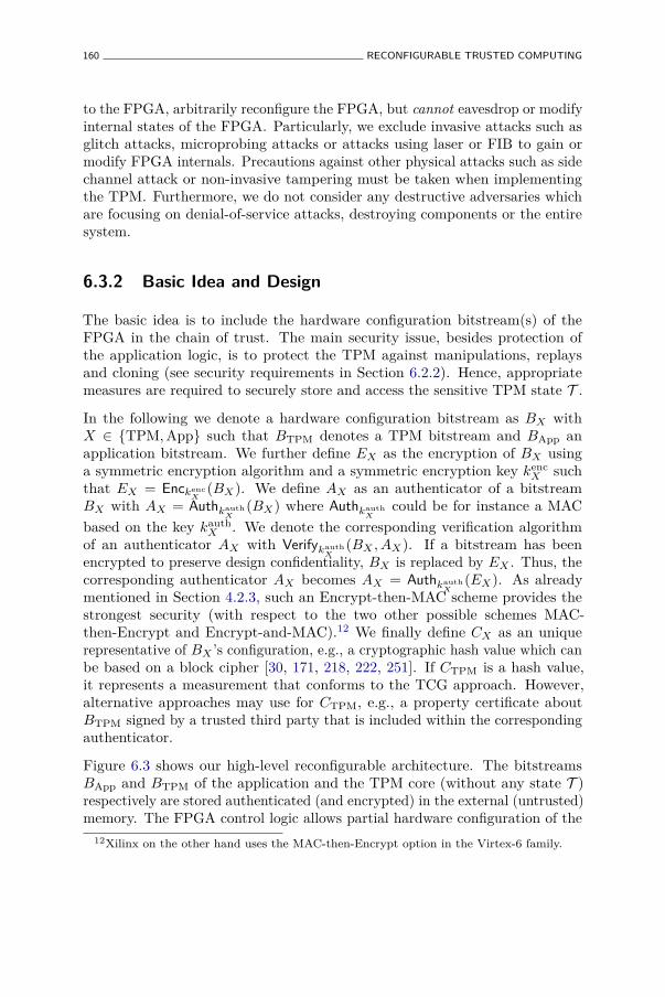
160 RECONFIGURABLE TRUSTED COMPUTING
to the FPGA, arbitrarily reconfigure the FPGA, but cannot eavesdrop or modifyinternal states of the FPGA. Particularly, we exclude invasive attacks such asglitch attacks, microprobing attacks or attacks using laser or FIB to gain ormodify FPGA internals. Precautions against other physical attacks such as sidechannel attack or non-invasive tampering must be taken when implementingthe TPM. Furthermore, we do not consider any destructive adversaries whichare focusing on denial-of-service attacks, destroying components or the entiresystem.
6.3.2 Basic Idea and Design
The basic idea is to include the hardware configuration bitstream(s) of theFPGA in the chain of trust. The main security issue, besides protection ofthe application logic, is to protect the TPM against manipulations, replaysand cloning (see security requirements in Section 6.2.2). Hence, appropriatemeasures are required to securely store and access the sensitive TPM state T .
In the following we denote a hardware configuration bitstream as BX withX ∈ TPM,App such that BTPM denotes a TPM bitstream and BApp anapplication bitstream. We further define EX as the encryption of BX usinga symmetric encryption algorithm and a symmetric encryption key kenc
X suchthat EX = Enckenc
X(BX). We define AX as an authenticator of a bitstream
BX with AX = AuthkauthX
(BX) where AuthkauthX
could be for instance a MACbased on the key kauth
X . We denote the corresponding verification algorithmof an authenticator AX with Verifykauth
X(BX , AX). If a bitstream has been
encrypted to preserve design confidentiality, BX is replaced by EX . Thus, thecorresponding authenticator AX becomes AX = Authkauth
X(EX). As already
mentioned in Section 4.2.3, such an Encrypt-then-MAC scheme provides thestrongest security (with respect to the two other possible schemes MAC-then-Encrypt and Encrypt-and-MAC).12 We finally define CX as an uniquerepresentative of BX ’s configuration, e.g., a cryptographic hash value which canbe based on a block cipher [30, 171, 218, 222, 251]. If CTPM is a hash value,it represents a measurement that conforms to the TCG approach. However,alternative approaches may use for CTPM, e.g., a property certificate aboutBTPM signed by a trusted third party that is included within the correspondingauthenticator.
Figure 6.3 shows our high-level reconfigurable architecture. The bitstreamsBApp and BTPM of the application and the TPM core (without any state T )respectively are stored authenticated (and encrypted) in the external (untrusted)memory. The FPGA control logic allows partial hardware configuration of the
12Xilinx on the other hand uses the MAC-then-Encrypt option in the Virtex-6 family.

TRUSTED FPGA ARCHITECTURE 161
Bitstream Protection Engine Bitstream Trust Engine
Application TPM
Reconfigurable Logic
External memory
FPGA
HCRAES
FPGA Controller
Load
Configure
Verify
Decrypt
ATPMBTPM
EApp AApp
TCG I/O
TkTPM kApp
Figure 6.3: Trusted FPGA architecture.
FPGA fabric to load the TPM and the application independently using theLoad and Configure interfaces.
The Bitstream Trust Engine (BTE) provides means to decrypt and verify theauthenticity and integrity of bitstreams using the Decrypt and Verify interfaces,which are already present in modern high-end FPGAs. Furthermore, theBTE includes a protected and non-volatile key storage to store the keys forbitstream decryption and authentication. Finally, the BTE provides a volatilememory location called Hardware Configuration Registers (HCRs) to store theconfiguration information of loaded bitstreams. These registers are used lateron by the TPM to set up its internal PCRs. In the following we define twostages in our protocol, the setup and the operational phase.
6.3.3 Setup Phase
To enable an FPGA with trusted computing functionality, a TPM issuerdesigns a TPM and synthesizes it to a (partial) bitstream BTPM for use on anFPGA. Furthermore, we assume that an application designer provides a trustedcomputing enabled FPGA application delivered as partial bitstream BApp which

162 RECONFIGURABLE TRUSTED COMPUTING
can interact with the TPM architecture using a well-defined interface. Of course,particularly when using an open TPM implementation, it is possible that bothcomponents are developed by a single party, e.g., by the system developer itself.
1. The system developer verifies the authenticity of BTPM and BApp, encryptsBApp to EApp and then creates bitstream authenticators ATPM and AAppusing the keys kauth
TPM and kauthApp respectively. Note that if TPM bitstream
BTPM is also provided by the system integrator itself, he can choosekauth
TPM = kauthApp .
2. The TPM bitstream BTPM, its authenticator ATPM, the encryptedapplication bitstream EApp, and its authenticator AApp are stored inthe external memory.
3. The system developer writes the appropriate authentication keys kauthTPM
and kauthApp (and the encryption key kenc
App) to the key store of the BTE.
6.3.4 Operational Phase
Remember that on each power-up the FPGA needs to reload its hardwareconfiguration from the external memory. Hence, for loading a trusted computingenabled application, the following steps need to be accomplished:
1. On device startup the FPGA controller reads the TPM bitstream BTPMand the corresponding authentication information ATPM from the externalmemory. BTE verifies the authenticity and integrity of BTPM basedon the authenticator ATPM by using Verifykauth
TPM(BTPM, ATPM). After
successful verification, BTE computes the configuration value CTPM ofthe TPM bitstream and writes CTPM into the first Hardware ConfigurationRegister (HCR) before the FPGA’s fabric is finally configured with BTPM.
2. The TPM requires exclusive access to a non-volatile memory location tostore its sensitive state T . Furthermore, the access to this storage locationis protected by the BTE which provides access to sensitive data onlywhen a specific bitstream (i.e., the TPM) is loaded. This access controlfunction is equivalent to TCG sealed storage. For full flexibility, the BTEimplements an interface with which a currently configured bitstream canrequest a reset (and implicitly, a clear) of the non-volatile memory toreassign the access to the storage for its own exclusive use. The accessauthorization to the memory for a loaded bitstream X can easily beperformed by BTE by checking its CX stored in the first HCR.

TRUSTED FPGA ARCHITECTURE 163
This step necessitates on-chip NVM, which, as discussed earlier, in practiceis rarely available in volatile FPGA. However, this restriction can beovercome with the state protection techniques described in Chapter 4,e.g., by extending the security perimeter to the external NVM (see alsoSection 6.2).
3. After the TPM has been loaded onto the fabric, the application bitstreamEApp and its authenticator AApp are read from the external memory,verified and decrypted in the same way. The BTE stores the configurationvalue CApp of the verified application in the second HCR register.
4. After the application bitstream has been configured in the fabric, thefirst call of the application to use the trusted computing functionalitywill initialize the TPM as follows. Based on the content of the twoHCR registers, the TPM initializes its own PCRs. It reads the recordedbitstream configurations (CTPM, CApp) and extends them in the PCRs.In this way the (unique) configurations of all bitstreams can be includedin the chain of trust. This is similar to the initialization of a desktop TPMvia CRTM. However, now the PCR includes the hardware measurementresults of the TPM itself.
After loading the hardware configuration of the TPM and the applicationinto the FPGA, the chain of trust can be extended by the measurements ofother specific platform components such as the operating system and high-levelapplication software. This allows to bind any higher level application (of the IPprovider) to the underlying FPGA by binding the application (or its data) usingthe subset of the PCR registers that contain the corresponding measurementsof the underlying FPGA.
6.3.5 TPM Updates
The update of the current TPM1 to another TPM2 on an FPGA is quite easywhen the sensitive state T does not need to be migrated. The TPM2 needs tobe loaded and will obviously not be able to access the BTE’s protected storagecontaining T of TPM1 (since TPM2 cannot provide CTPM1). Hence, TPM2reassigns the protected storage to be able to create and store its own T . Withthe reset of the protected storage, the previous T in the non-volatile memoryis cleared so that no confidential information of TPM1 will be accessible forTPM2. To prevent denial-of-service attacks against T , BTE can additionallyimplement a mechanism such that TPM1 has to clear its T before TPM2 isable to reassigns the protected storage for its own T .

164 RECONFIGURABLE TRUSTED COMPUTING
However, for migrating T from TPM1 to TPM2 without loss of T , wepropose to extend existing TPM implementations by a migration function13
Migrate(Aupdate, CTPM2) where Aupdate is an update authenticator and CTPM2
a unique reference to the corresponding TPM2. For a TPM update, a systemdeveloper (who has set kauth
TPM for the corresponding FPGA) generates an updateauthenticator
Aupdate = signSKupdate(CTPM2 , PTPM) ,
where SKupdate denotes an update signing key. TPM1 trusts the correspondingupdate verification key PKupdate, e.g., as it is pre-installed in TPM1.
Thus TPM1 knows a set of trusted update authorities (the system developer,etc.) who are allowed to perform the migration of T for use with TPM2. PTPMdenotes a reference to the class of TPMs that provides a certain (minimum)set of security properties. Note that PTPM can also be replaced by individualupdate signing keys each representing a single security property.
When the user requests a TPM update, he invokes the migration function ofTPM1 using the parameters Aupdate and CTPM2 received from the correspondingsystem developer (over an untrusted channel). Then, the migration functionMigrate(Aupdate, CTPM2) of TPM1 performs the following steps:
1. It verifies Aupdate using the update verification key PKupdate and checkswhether PTPM2 provides the same (minimum) set of security propertiesas PTPM1 .
2. After successful verification, it reassigns the BTE’s protected storage,which contains T , for use with TPM2. The BTE needs to grant TPM2access to the protected NVM without erasing its content. More precisely,the BTE provides an interface so that only TPM1 can associate theprotected storage with CTPM2 . After reassignment of the protectedmemory, only the new TPM2 is able to access T .
After the migration function has terminated, the application (or manually, theuser) overwrites TPM1 stored in the external memory with BTPM2 and thecorresponding authenticator ATPM2 . Now, the user restarts the FPGA to reloadthe updated TPM and application.
13Note, our migration functionality does not replace the TCG mechanisms for migratinginternals called TPM_Migration and TPM_Maintenance.

TRUSTED FPGA ARCHITECTURE 165
6.3.6 Discussion
Advantages
Enhancing an FPGA with trusted computing mechanisms in reconfigurablelogic can provide the following benefits.
Enhancing the Chain of Trust. As explained in Section 2.1, TPM-enabledsystems establish the chain of trust by starting from the CRTM, which iscurrently part of the BIOS. For FPGA hosted TPMs, the BTE can begin withthe hardware configuration of the application and even with the TPM itself.Therefore, the chain of trust can include the underlying hardware as well as theTPM hardware configuration, i.e., the chain of trust paradigm can be moved tothe hardware level.
Flexible Usage of TPM Functionality. The developer may also utilize thebasic functionality of the TPM in his application which can make thedevelopment of additional cryptographic units obsolete. This includes thegeneration of true random numbers, the asymmetric cryptographic engine as wellas protected non-volatile memory. Furthermore, a flexible FPGA design allowsto use only the specific TPM functionality that is required for the application,yielding a smaller and consequently easier to certify implementation.
Flexible Update of TPM Functionality. A TPM implemented in reconfig-urable logic of an FPGA can easily be adapted to new requirements or versions.For example, if the default hash function turns out to be not secure enough,an FPGA hosted TPM could include a self-modification feature which updatesthe corresponding hash function component, in particular no new hardwaredesign is needed. Moreover, patches fixing potential implementation errors orchanges/updates enhancing interoperability could be applied quickly and veryeasily.
Improved Communication Security. The integration of CPU, ROM, RAMand TPM into a single chip enhances the protection of communicationlinks between these security critical components from being intercepted ormanipulated. Having the boot ROM and RAM integrated on the FPGA chip,makes the injection of malicious boot code or RAM manipulations more difficult.

166 RECONFIGURABLE TRUSTED COMPUTING
Vendor Independence. Platform owners can select which TPM implemen-tation is operated on their platforms. This allows even the usage of fullyvendor independent open TPM implementations providing more assuranceregarding trapdoors and Trojans. Moreover, since we can easily implementa TPM soft core into hardware, a multitude of vendors can offer a variety ofTPM implementations. Thus, users are not only restricted to a few TPM ASICmanufacturers as today, they even can implement their own TPM instancesand have it certified for TCG compliance by a trustworthy authority. In thisscenario the users do not have to trust any external entity, except for the FPGAmanufacturer.
Implementation Aspects
Our trusted FPGA architecture uses a number of features that are alreadypresent in some commercial FPGAs: partial reconfiguration, bitstreamauthentication, bitstream encryption and embedded Flash memory. Thissuggests that a practical implementation of our proposal is technically feasibletoday. The main components of the BTE that are currently missing, are thehardware configuration registers and the access control mechanism for theembedded NVM.
In order to realize the former, the FPGA controller must be extended tomeasure and record the loaded bitstreams and an interface must be providedto the reconfigurable logic to read the content of the HCRs. Xilinx FPGAsalready have a so-called Internal Configuration Access Port (ICAP) primitivethat provides the reconfigurable user logic access to the FPGA’s configurationinterface and that enables internal readback and (partial) self-reconfiguration.It seems natural to expose the HCRs using this ICAP interface.
The protected storage on the other hand requires a more tight integration ofthe embedded Flash memory and the FPGA controller. Access to the memoryaddresses that are used to store the persistent state T must only be granted ifthe expected bitstream BTPM has been recorded in the HCR register.
6.4 Conclusion
In Chapter 4 we explained that it is sometimes desirable to embed a trustedcomputing module in a hardware component that lacks reprogrammable non-volatile memory. One of the examples that we gave, is trusted computing onreconfigurable hardware. In this chapter we explored this example in moredetail and we investigated how a trusted module can be implemented on modern

CONCLUSION 167
FPGAs, mainly focussing on the protection of the trusted module’s persistentstate.
We first provided a brief overview of the attacks on FPGAs, such as bitstreamcloning and reverse engineering, and of the defense mechanisms that are presentlyavailable in commercial FPGA products. Most security problems arise fromthe fact that the configuration bitstream of volatile FPGAs, which containsintellectual property or security sensitive information, is stored in externalNVM, and that it is consequently possible to read and/or modify the bitstreamthat is loaded on the FPGA. The most popular defense mechanism are schemesto bind the bitstream to a unique device and the encryption of the bitstream.The latter requires some embedded non-volatile memory, typically fuses orbattery-backed RAM, to store the bitstream decryption key.
Next we discussed how to protect the persistent state when implementinga trusted module on commercial FPGAs. The state protection schemes,which we described in Chapter 4, require the storage of a secret key anda source of freshness inside the trusted module. We observed that PUFs canuniquely fingerprint an FPGA and hence that they are well suited to derive thesecret key(s) of the state protection scheme. In our discussion we postulatedthat it is complex to extract a PUF-derived key by reverse engineering aconfiguration bitstream. If the underlying FPGA supports bitstream encryption,this assumption must not be made. The detection of state replay proveschallenging on a volatile FPGA that does not have embedded non-volatilememory and the only proper solution is to extend the security perimeter to theexternal NVM with a cryptographic protocol.
Finally, we described a trusted FPGA architecture that improves upon solutionsfor bitstream encryption and bitstream authentication which are present intoday’s commercial FPGAs. We defined a bitstream trust engine that acts asa root of trust to measure and report the integrity of partial bitstreams. Thescheme goes a step further than the µTPM architecture that was described inthe previous chapter, as it allows to attest not only the integrity of the TPM’sfirmware, but also the integrity of the configuration bitstream that representsthe TPM’s hardware.


Chapter 7
Conclusions and Future Work
7.1 Conclusions
This thesis deals with the analysis and design of trusted computing platforms. Inour analysis we focussed primarily on the TCG specifications, which introducedthe concept of a trusted computing platform that supports remote attestationand sealed storage. Trusted computing technology is considered as a promisingenabling technology to improve the trustworthiness of computing platforms.
More than 600 million PCs and laptops have been sold equipped with a TPM,but enterprises have yet to embrace the technology on a large scale. One of thereasons for this limited success is the lack of adequate operating system support.This situation might changed drastically with the arrival of Windows 8. In earlierversions of Windows, the TPM was only used by BitLocker drive encryption torecord the integrity of the early boot process (i.e., BIOS and bootloader) andto unseal the disk encryption key. Windows 8 goes much further: it records theintegrity of all boot components (including bootloader, kernel, device drivers,and anti-malware software), it supports remote attestation, it offers TPM-basedcertificate storage, it enables the TPM to acts like a permanently inserted smartcard, and it has TPM provisioning software.
The MTM specification of the TCG tried to adapt the TPM to requirementsof the mobile phone platform and it can be seen as an attempt to standardizesecure boot on mobile phones. This specification has been far less successfulthan the TPM standard, and it has not been adopted by manufacturers. Webelieve that there are two main reasons for the failure of this attempt. On theone hand, the mobile phone market is a lot more competitive than the PC world
169

170 CONCLUSIONS AND FUTURE WORK
where Intel and Microsoft define the platform. Various processor manufacturersand multiple operating systems (e.g., Android, iOS, Windows Phone, BlackberryOS) exist, which presumably makes it more difficult to agree on a commonspecification. On the other hand, smart phone platforms are more modern andhence hampered less by backward compatibility requirements. Many mobilephone manufacturers already implement a secure boot mechanism without anMTM, e.g., in order to restrict the phone to a specific mobile operator or toexercise strict control on the applications that get executed on the phones. iOSis the prime example of a mobile ecosystem that relies heavily on code signing.Apple wants that all third party applications are installed through its AppStore. A bonus of its closed model is that very few malware exists for the iOSplatform.
In Chapter 2 we explained that the TCG’s binary attestation approach hassome inherent shortcomings. First, it is hard to manage on a large scale becausea large number of valid platform configurations could exist and because everysoftware update will yield a different integrity measurement. Second, it onlyprovides assurance about software components that get loaded at boot time, andconsequently the platform can still be compromised at runtime. In Chapter 2 wealso described an alternative attestation scheme that combines the computationof a runtime memory checksum with the timestamping functionality of theTPM. This scheme requires minimal software support as it only relies on aTPM device driver and optionally a trusted bootloader.
Chapter 3 dealt with the resilience of trusted computing platforms againsthardware attacks. Although the TCG specifications only consider softwareattacks, most TPM implementations are based on a secure microcontroller seriesand hence apply countermeasures against physical attacks. In this chapter, weinvestigated which operations, at least in theory, can be targeted with a sidechannel attack in order to extract the TPM’s internal secrets. It remains tobe seen how difficult this type of attacks is in practice, but it is clear that anycryptographic implementation can be attacked with sufficient resources. Themain conclusion of this chapter, however, is that the communication interface ofthe TPM is a more attractive attack target. Physical attacks on this interfaceare not that difficult to perform and require relatively inexpensive equipment,yet they have severe security implications. For instance, cryptographic keys canbe captured on the communication bus when they are unsealed, or a TPM resetattack can be used to circumvent the static CRTM. An effective countermeasureagainst this type of attacks is the integration of the TPM in the chipset, likedone by Intel, since it is much more difficult to access and monitor the front-sidebus of a PC.
In Chapter 4 we addressed one of the main challenges for integrated TPMs andMTMs, namely the secure storage of its persistent state in external non-volatile

CONCLUSIONS 171
memory. We proposed to encrypt and authenticate the externalized state with asecret key that is embedded inside the trusted module. In addition, we proposedto detect replay of older versions of the state either by including a nonce in thestate or by updating the secret key. With either approach, the trusted modulestill needs a small amount of on-chip reprogrammable non-volatile memory.Since Flash memory can often not be embedded in a cost effective manner, therequired on-chip NVM must be implemented with another technology. Battery-backed SRAM is a popular choice; this option is for instance used in IBM securecoprocessor products and in FPGAs with bitstream encryption support. If theexpected number of state updates is finite and rather small, fuses can be usedto implement a monotonic counter; this option is for instance used in gameconsoles to prevent software downgrading. In Chapter 4 we introduced twoalternative solutions that do not require embedded reprogrammable NVM. Thefirst solution derives an updatable state protection key from a reconfigurablePUF, whereas the second extends the security perimeter of the trusted moduleto the external NVM chip with a cryptographic protocol. For the time being, thefirst approach remains theoretical in nature, because good practical realizationsof the RPUF concept have yet to be found.
The TPM enables novel functionalities such as remote attestation and sealedstorage, but it can also be used as a traditional cryptographic coprocessor, e.g.,to generate RSA signatures, to maintain a monotonic counter or to generaterandom numbers. On most platforms third-party software can access the TPMusing a Public Key Cryptography Standards (PKCS)#11 interface and withMicrosoft Crypto API. For some applications, however, it would be useful ifthe platform had a secure coprocessor that is freely programmable and that canhost multiple applications. In Chapter 5 we introduced the µTPM architecturefor a secure coprocessor. The proposed architecture is inspired by the JavaCardframework, particularly with regard to its multiprocessing support. It can beused to implement a conventional TPM, but it can also run arbitrary securitytasks. Two important features differentiate the µTPM architecture from theJavaCard architecture. First, the program code of the µTPM is stored inexternal NVM and gets loaded in internal RAM when needed. In order to keepthe size of the embedded RAM small, we propose to split the TPM firmware intodifferent code fragments, each operating on a shared state, and to only load onefragment at once. Second, the µTPM architecture adopts the trusted computingprinciple of measured boot. The µTPM can execute arbitrary program code,but the integrity of code gets measured and it can be reported afterwards.
FPGA devices have become big enough to implement complex reconfigurableSoC designs that contain a softcore processor (e.g., MicroBlaze) and thatare capable of hosting an operating system such as Linux. In Chapter 6 weinvestigated how a TPM or MTM can be integrated into a reconfigurable SoC

172 CONCLUSIONS AND FUTURE WORK
design. With an FPGA implementation of the TPM standard, it is possibleto upgrade the TPM firmware as well as its hardware. Two main topicswere covered in this chapter: the protection of the persistent state and theprotection of the configuration bitstream on commercially available FPGAs.Since SRAM-based FPGAs typically lack on-chip non-volatile memory, thetechniques of Chapter 4 were used to securely externalize the trusted module’spersistent module. Furthermore, we introduced PUFs as a technology to derivecryptographic keys on an FPGA, instead of embedding them directly in theconfiguration bitstream. Finally, we also designed a trusted FPGA architecturethat adopts the TCG principle of measured boot and sealed storage.
7.2 Directions for Future Research
The publication of the TCG specifications has lead to an active researchcommunity in the field of trusted computing. Significant contributions have beenmade in this research domain, including the analysis of the TCG specifications,applications of trusted computing technology, alternative approaches for remoteattestation, improvements to the DAA protocol, software support for trustedcomputing, etc. In this thesis we covered a number of research topics in thearea of trusted computing, most of which deal with hardware aspects. We seethat there are still some open research questions and interesting directions forfuture research.
Attacks on Trusted Computing Platforms. In Chapter 3, we did a theoreticalanalysis of side channel attacks on the TPM. It remains to be investigatedhow difficult these attacks are in practice on existing TPM implementations.The experiments Kovah et al. [159] with the TPM tick stamping functionalityindicate that the Broadcom TPM might be vulnerable to timing attacks. Ofcourse the question can be raised whether the scientific community shouldperform a security analysis of commercial products. However, this analysis canprovide users more confidence in trusted computing technology in general andin specific solutions.
The TCG is currently working on specifications for a next generation of trustedmodules, namely for a TPM 2.0 and for an MTM 2.0. In October 2012 adraft of the TPM 2.0 specification has been published for public review. Aspointed out in Chapter 3, some minor flaws were found in the TPM 1.1b and1.2 specifications. So it is essential that the 2.0 specification gets scrutinized bythe community.

DIRECTIONS FOR FUTURE RESEARCH 173
Lightweight Trusted Computing. The TCG specifications and the accompa-nying extensions to the x86 processor enable new security features such asmeasured boot, remote attestation and sealed storage on the PC platform.Even though the MTM specification has not been adopted, mobile phonemanufacturers are starting to include hardware support (e.g., ARM TrustZone,TI M-Shield, embedded SE) for a trusted execution environment. The TCGEmbedded Systems Work Group has yet to release any specifications, but, inthe meantime, manufacturers are offering TPM variants with a communicationinterface (i.e., I2C or SPI) that is more suited for non-PC platforms.
We believe that there is a need for a more minimal root of trust for embeddedsystems. It is not viable to add a TPM, which in essence is a microcontrollerwith a RSA coprocessor, to a low-end embedded device. Several software-basedremote attestation schemes (e.g., [238]) have been proposed for embeddedsystems, but they are vulnerable to simple hardware attacks (e.g., increasing themicrocontroller’s clock frequency) and to the proxy attack that was describedin Chapter 2. However, with minor hardware changes, better schemes canbe devised. For instance, Schulz et al. [232, 233] constructed a lightweightsolution that combines software-based attestation with a PUF. Other promisingapproaches are the self-protecting modules of Strackx et al. [261, 262] and theSMART scheme of El Defrawy et al. [70], which both use a program-counterdependent memory access control model.
Physical Unclonable Functions. In this thesis, we repeatedly used PUFs toderive cryptographic keys. PUF-based key storage is interesting for cost reasons,as it provides an alternative for OTP NVM technology, and from a securityrespective, because the key is not present when the device is powered off. VariousPUF constructions have been proposed in the literature. However, an thoroughsecurity analysis of these PUF constructions, in particular regarding theirresilience to physical attacks, is missing. Initial work on side channel analysisof PUFs and fuzzy extractors has been presented by Merli et al. [197, 198], butmore elaborate research efforts are needed. One concrete idea that is worthinvestigating, is to verify whether the frequency injection techniques that havebeen proposed by Markettos and Moore [189] and by Bayon et al. [17] to attackring oscillator based TRNGs can also be applied on ring oscillator PUFs.
We believe that there is a need for more research on PUFs that are intrinsicallypresent in existing platforms. Intrinsic PUFs are for instance useful to derive asecret key for a software TPM or to bind software to a specific platform. Memorybased PUFs (e.g., SRAM PUF) have been found in existing platforms. Holcombet al. [132, 133] used the SRAM startup state to derive a fingerprint on themicrocontroller of an RFID tag. In September 2012 the PUFFIN project, which

174 CONCLUSIONS AND FUTURE WORK
looks for PUFs in standard computer components, announced1 that SRAMPUFs can be found in graphics cards of computers. Other interesting new resultsare the work on extracting a fingerprint from Flash memory [217, 295] and themicroprocessor-intrinsic PUF construction of Maiti and Schaumont [186].
In Chapter 4 we introduced the concept of a reconfigurable PUF and weillustrated how this new security primitive can be used to protect the persistentstate of a trusted module in external NVM. Practical realizations of thistheoretical concept, preferably in silicon, remain an open issue. One possibleapproach could be to exploit transistor aging. Logically reconfigurable PUFsare a good emulation from a behavioral perspective, but they do not achieve thestrong security properties of a physically reconfigurable PUF and they requireembedded NVM to store an internal state.
FPGA Security. In Chapter 6, we assumed that it is practically infeasible toreverse engineer a PUF from a configuration bitstream. This assumption ismotivated by the fact that existing bitstream reversal tools such as Debit [203]and BIL [23] can only reverse engineer bitstreams partially. Full bitstreamreversal remains an open problem.
In general, more research is needed to evaluate the security of PUF-based keystorage on FPGAs. Reverse engineering of the bitstream in order to determinethe type and location of the PUF in the reconfigurable logic is one attackscenario. In his thesis [79] Drimer described how internal state changes can beobserved with the FPGA’s readback functionality. Perhaps this active readbackdifference attack can be used to read the PUF response or the derived key.Finally, as mentioned above, the PUF and the fuzzy extractor can also betargeted with a side channel attack.
1http://puffin.eu.org/20120927.html

Bibliography
[1] Actel. The Importance of Design Security: Protecting Your Investment,2005. http://www.actel.com/documents/Security_PIB.pdf.
[2] Agrawal, D., Archambeault, B., Rao, J. R., and Rohatgi, P. TheEM Side-Channel(s). In 4th International Workshop on CryptographicHardware and Embedded Systems (CHES 2002) (2002), B. S. KaliskiJr., Çetin Kaya Koç, and C. Paar, Eds., vol. 2523 of Lecture Notes inComputer Science, Springer, pp. 29–45.
[3] Altera. An FPGA Design Security Solution Using a Secure MemoryDevice, Oct. 2007. http://www.altera.com/literature/wp/wp-01033.pdf.
[4] Alves, T., and Rudelic, J. ARM Security Solutions and IntelAuthenticated Flash, 2007.
[5] Anderson, R. J., and Kuhn, M. G. Tamper Resistance – a CautionaryNote. In 2nd USENIX Workshop on Electronic Commerce (EC 1996)(1996), USENIX, pp. 1–11.
[6] Anderson, R. J., and Kuhn, M. G. Low Cost Attacks on TamperResistant Devices. In 5th International Workshop on Security Protocols(1998), B. Christianson, B. Crispo, T. M. A. Lomas, and M. Roe, Eds.,vol. 1361 of Lecture Notes in Computer Science, Springer, pp. 125–136.
[7] Arbaugh, W. A. Chaining Layered Integrity Checks. PhD thesis,University of Pennsylvania, 1999.
[8] Arbaugh, W. A., Farber, D. J., and Smith, J. M. A Secure andReliable Bootstrap Architecture. In 1997 IEEE Symposium on Securityand Privacy (S&P 1997) (1997), IEEE, pp. 65–71.
175

176 BIBLIOGRAPHY
[9] Arbaugh, W. A., Keromytis, A. D., Farber, D. J., and Smith,J. M. Automated Recovery in a Secure Bootstrap Process. In Networkand Distributed System Security Symposium (NDSS 1998) (1998), TheInternet Society.
[10] Armknecht, F., Maes, R., Sadeghi, A.-R., Sunar, B., and Tuyls,P. Memory Leakage-Resilient Encryption Based on Physically UnclonableFunctions. In Advances in Cryptology – ASIACRYPT 2009 (2009),M. Matsui, Ed., vol. 5912 of Lecture Notes in Computer Science, Springer,pp. 685–702.
[11] Asokan, N., Ekberg, J.-E., and Paatero, L. Method, system andcomputer program product for a trusted counter in an external securityelement for secure a personal communication device, Feb. 2007. US patent7178041 B2.
[12] Aucsmith, D. Tamper Resistant Software: An Implementation. In 1stInternational Workshop on Information Hiding (IH 1996) (1996), R. J.Anderson, Ed., vol. 1174 of Lecture Notes in Computer Science, Springer,pp. 317–333.
[13] Azema, J., and Fayad, G. M-Shield™Mobile Security TechnologyWhite Paper. Tech. rep., Texas Instruments, Feb. 2008.
[14] Baetoniu, C., and Sheth, S. FPGA IFF Copy Pro-tection Using Dallas Semiconductor/Maxim DS2432 Secure EEP-ROMs, May 2010. http://www.xilinx.com/support/documentation/application_notes/xapp780.pdf.
[15] Bar-El, H., Choukri, H., Naccache, D., Tunstall, M., andWhelana, C. The Sorcerer’s Apprentice Guide to Fault Attacks.Proceedings of the IEEE 94, 2 (2006), 370–382.
[16] Barham, P., Dragovic, B., Fraser, K., Hand, S., Harris, T. L.,Ho, A., Neugebauer, R., Pratt, I., and Warfield, A. Xen andthe Art of Virtualization. In 19th ACM Symposium on Operating SystemsPrinciples (SOSP 2003) (2003), M. L. Scott and L. L. Peterson, Eds.,ACM, pp. 164–177.
[17] Bayon, P., Bossuet, L., Aubert, A., Fischer, V., Poucheret, F.,Robisson, B., and Maurine, P. Contactless Electromagnetic ActiveAttack on Ring Oscillator Based True Random Number Generator. In3rd International Workshop on Constructive Side-Channel Analysis andSecure Design (COSADE 2012) (2012), W. Schindler and S. A. Huss, Eds.,vol. 7275 of Lecture Notes in Computer Science, Springer, pp. 151–166.
BIBLIOGRAPHY 177
[18] Becher, M., Dornseif, M., and Klein, C. N. FireWire: all yourmemory are belong to us. In CanSecWest 2005 (2005).
[19] Bellare, M., Canetti, R., and Krawczyk, H. Keying HashFunctions for Message Authentication. In Advances in Cryptology –CRYPTO 1996 (1996), N. Koblitz, Ed., vol. 1109 of Lecture Notes inComputer Science, Springer, pp. 1–15.
[20] Bellare, M., Goldreich, O., and Goldwasser, S. IncrementalCryptography: The Case of Hashing and Signing. In Advances inCryptology – CRYPTO 1994 (1994), Y. Desmedt, Ed., vol. 839 of LectureNotes in Computer Science, Springer, pp. 216–233.
[21] Bellare, M., and Namprempre, C. Authenticated Encryption:Relations among Notions and Analysis of the Generic CompositionParadigm. In Advances in Cryptology – ASIACRYPT 2000 (2000),T. Okamoto, Ed., vol. 1976 of Lecture Notes in Computer Science, Springer,pp. 531–545.
[22] Bellare, M., Rogaway, P., and Wagner, D. The EAX Mode ofOperation. In 11th International Workshop on Fast Software Encryption(FSE 2004) (2004), B. K. Roy and W. Meier, Eds., vol. 3017 of LectureNotes in Computer Science, Springer, pp. 389–407.
[23] Benz, F., Seffrin, A., and Huss, S. A. BIL: A Tool-Chain forBitstream Reverse-Engineering. In 22nd International Conference onField Programmable Logic and Applications (FPL 2012) (2012), IEEE,pp. 735–738.
[24] Berger, S., Cáceres, R., Goldman, K. A., Perez, R., Sailer, R.,and van Doorn, L. vTPM: Virtualizing the Trusted Platform Module.In 15th USENIX Security Symposium (2006), USENIX, pp. 305–320.
[25] Biham, E., and Shamir, A. Differential Fault Analysis of Secret KeyCryptosystems. In Advances in Cryptology – CRYPTO 1997 (1997), B. S.Kaliski Jr., Ed., vol. 1294 of Lecture Notes in Computer Science, Springer,pp. 513–525.
[26] Billet, O., Gilbert, H., and Ech-Chatbi, C. Cryptanalysis of aWhite Box AES Implementation. In 11th International Workshop onSelected Areas in Cryptography (SAC 2004) (2004), H. Handschuh andM. A. Hasan, Eds., vol. 3357 of Lecture Notes in Computer Science,Springer, pp. 227–240.
[27] Black, J. Authenticated encryption. In Encyclopedia of Cryptographyand Security, H. C. A. van Tilborg, Ed. Springer, 2005.

178 BIBLIOGRAPHY
[28] Black, J., Halevi, S., Krawczyk, H., Krovetz, T., and Rogaway,P. UMAC: Fast and Secure Message Authentication. In Advances inCryptology – CRYPTO 1999 (1999), M. J. Wiener, Ed., vol. 1666 ofLecture Notes in Computer Science, Springer, pp. 216–233.
[29] Black, J., and Rogaway, P. CBC MACs for Arbitrary-LengthMessages: The Three-Key Constructions. In Advances in Cryptology– CRYPTO 2000 (2000), M. Bellare, Ed., vol. 1880 of Lecture Notes inComputer Science, Springer, pp. 197–215.
[30] Black, J., Rogaway, P., and Shrimpton, T. Black-Box Analysisof the Block-Cipher-Based Hash-Function Constructions from PGV. InAdvances in Cryptology – CRYPTO 2002 (2002), M. Yung, Ed., vol. 2442of Lecture Notes in Computer Science, Springer, pp. 320–335.
[31] Boileau, A. Hit by a Bus: Physical Access Attacks with Firewire. InRuxcon 2006 (2006).
[32] Bond, M. Attacks on Cryptoprocessor Transaction Sets. In 3rdInternational Workshop on Cryptographic Hardware and EmbeddedSystems (CHES 2001) (2001), Çetin Kaya Koç, D. Naccache, and C. Paar,Eds., vol. 2162 of Lecture Notes in Computer Science, Springer, pp. 220–234.
[33] Boneh, D., DeMillo, R. A., and Lipton, R. J. On the Importanceof Checking Cryptographic Protocols for Faults (Extended Abstract). InAdvances in Cryptology – EUROCRYPT 1997 (1997), W. Fumy, Ed.,vol. 1233 of Lecture Notes in Computer Science, Springer, pp. 37–51.
[34] Borghoff, J., Canteaut, A., Güneysu, T., Kavun, E. B.,Knezevic, M., Knudsen, L. R., Leander, G., Nikov, V., Paar,C., Rechberger, C., Rombouts, P., Thomsen, S. S., and Yalçin,T. PRINCE – A Low-Latency Block Cipher for Pervasive ComputingApplications. In Advances in Cryptology – ASIACRYPT 2012 (2012),X. Wang and K. Sako, Eds., vol. 7658 of Lecture Notes in ComputerScience, Springer, pp. 208–225.
[35] Bösch, C., Guajardo, J., Sadeghi, A.-R., Shokrollahi, J.,and Tuyls, P. Efficient Helper Data Key Extractor on FPGAs. In10th International Workshop on Cryptographic Hardware and EmbeddedSystems (CHES 2008) (2008), E. Oswald and P. Rohatgi, Eds., vol. 5154of Lecture Notes in Computer Science, Springer, pp. 181–197.
[36] Boyen, X. Robust and Reusable Fuzzy Extractors. In Security with NoisyData: On Private Biometrics, Secure Key Storage and Anti-Counterfeiting.Springer, 2007, ch. 6, pp. 101–112.

BIBLIOGRAPHY 179
[37] Bratus, S., D’Cunha, N., Sparks, E., and Smith, S. W. TOCTOU,Traps, and Trusted Computing. In 1st International Conference on TrustedComputing and Trust in Information Technologies (Trust 2008) (2008),P. Lipp, A.-R. Sadeghi, and K.-M. Koch, Eds., vol. 4968 of Lecture Notesin Computer Science, Springer, pp. 14–32.
[38] Brickell, E. F., Camenisch, J., and Chen, L. Direct AnonymousAttestation. In 11th ACM Conference on Computer and CommunicationsSecurity (CCS 2004) (2004), V. Atluri, B. Pfitzmann, and P. D. McDaniel,Eds., ACM, pp. 132–145.
[39] Bruschi, D., Cavallaro, L., Lanzi, A., and Monga, M. ReplayAttack in TCG Specification and Solution. In 21th Annual ComputerSecurity Applications Conference (ACSAC 2005) (2005), IEEE, pp. 127–137.
[40] BSI. Federal Government’s Comments on the TCG and NGSCB in theField of Trusted Computing. https://www.bsi.bund.de/cae/servlet/contentblob/483110/publicationFile/30569/StellungnahmeTCG1_2a_e_pdf.pdf.
[41] Buysschaert, P., De Mulder, E., Örs, S. B., Delmotte,P., Preneel, B., Vandenbosch, G., and Verbauwhede, I.Electromagnetic Analysis Attack on an FPGA Implementation of anElliptic Curve Cryptosystem. In The International Conference on"Computer as a Tool" (EUROCON 2005) (2005), vol. 2, IEEE, pp. 1879–1882.
[42] Camenisch, J. Better Privacy for Trusted Computing Platforms:(Extended Abstract). In 9th European Symposium on Research InComputer Security (ESORICS 2004) (2004), P. Samarati, P. Y. A. Ryan,D. Gollmann, and R. Molva, Eds., vol. 3193 of Lecture Notes in ComputerScience, Springer, pp. 73–88.
[43] Carlier, V., Chabanne, H., Dottax, E., and Pelletier, H.Electromagnetic Side Channels of an FPGA Implementation of AES.Cryptology ePrint Archive, Report 2004/145, 2004.
[44] Carrier, B. D., and Grand, J. A hardware-based memory acquisitionprocedure for digital investigations. Digital Investigation 1, 1 (2004),50–60.
[45] Castillo, E., Parrilla, L., García, A., Lloris, A., and Meyer-Baese, U. Intellectual Property Protection of HDL IP Cores ThroughAutomated Signature Hosting. In 17th International Conference on Field

180 BIBLIOGRAPHY
Programmable Logic and Applications (FPL 2007) (Aug. 2007), IEEE,pp. 183–188.
[46] Ceccato, M., Preda, M. D., Nagra, J., Collberg, C., andTonella, P. Barrier Slicing for Remote Software Trusting. In 7thIEEE International Workshop on Source Code Analysis and Manipulation(SCAM 2007) (2007), IEEE, pp. 27–36.
[47] Ceccato, M., Preda, M. D., Nagra, J., Collberg, C., andTonella, P. Trading-off Security and Performance in Barrier Slicingfor Remote Software Entrusting. Automated Software Engineering 16, 2(2009), 235–261.
[48] Ceccato, M., and Tonella, P. CodeBender: Remote SoftwareProtection Using Orthogonal Replacement. IEEE Software 28, 2 (2011),28–34.
[49] Ceccato, M., Tonella, P., Preda, M. D., and Majumdar, A.Remote software protection by orthogonal client replacement. In 24thACM Symposium on Applied Computing (SAC 2009) (2009), S. Y. Shinand S. Ossowski, Eds., ACM, pp. 448–455.
[50] Cesena, E., Ramunno, G., Sassu, R., Vernizzi, D., and Lioy, A.On Scalability of Remote Attestation. In 6th ACM Workshop on ScalableTrusted Computing (STC 2011) (2011), Y. Chen, S. Xu, A.-R. Sadeghi,and X. Zhang, Eds., ACM, pp. 25–30.
[51] Challener, D., Yoder, K., Catherman, R., Safford, D., andvan Doorn, L. A Practical Guide to Trusted Computing. IBM Press,2008.
[52] Chang, H., and Atallah, M. J. Protecting Software Code byGuards. In 1st ACM Workshop on Security and Privacy in Digital RightsManagement (DRM 2001) (2002), vol. 2320 of Lecture Notes in ComputerScience, Springer, pp. 160–175.
[53] Chari, S., Rao, J. R., and Rohatgi, P. Template Attacks. In4th International Workshop on Cryptographic Hardware and EmbeddedSystems (CHES 2002) (2003), B. S. Kaliski Jr., Çetin Kaya Koç, andC. Paar, Eds., vol. 2523 of Lecture Notes in Computer Science, Springer,pp. 13–28.
[54] Chen, L., and Ryan, M. D. Offline dictionary attack on TCG TPMweak authorisation data, and solution. In 1st International Conference onFuture of Trust in Computing (2008), Vieweg & Teubner, pp. 193–196.

BIBLIOGRAPHY 181
[55] Chen, L., and Ryan, M. D. Attack, Solution and Verification forShared Authorisation Data in TCG TPM. In 6th International Workshopon Formal Aspects in Security and Trust (FAST 2009) (2010), P. Deganoand J. D. Guttman, Eds., vol. 5983 of Lecture Notes in Computer Science,Springer, pp. 201–216.
[56] Chen, Z. Java Card™Technology for Smart Cards: Architecture andProgrammer’s Guide. Addison-Wesley Professional, 2000.
[57] Chevallier-Mames, B., Naccache, D., Paillier, P., andPointcheval, D. How to Disembed a Program? In 6th InternationalWorkshop on Cryptographic Hardware and Embedded Systems (CHES2004) (2004), M. Joye and J.-J. Quisquater, Eds., vol. 3156 of LectureNotes in Computer Science, Springer, pp. 441–454.
[58] Chevallier-Mames, B., Naccache, D., Paillier, P., andPointcheval, D. How to Disembed a Program? Cryptology ePrintArchive, Report 2004/138, 2004.
[59] Chiu, Y.-H., Liao, Y.-B., Chiang, M.-H., Lin, C.-L., Hsu, W.-C.,Chiang, P.-C., Hsu, Y.-Y., Liu, W.-H., Sheu, S.-S., Su, K.-L.,Kao, M.-J., and Tsai, M.-J. Impact of Resistance Drift on MultilevelPCM Design. In 2010 IEEE International Conference on IC Design andTechnology (ICICDT 2010) (2010), pp. 20–23.
[60] Chow, S., Eisen, P. A., Johnson, H., and van Oorschot, P. C.A White-Box DES Implementation for DRM Applications. In 2nd ACMWorkshop on Security and Privacy in Digital Rights Management (DRM2002) (2003), J. Feigenbaum, Ed., vol. 2696 of Lecture Notes in ComputerScience, Springer, pp. 1–15.
[61] Chow, S., Eisen, P. A., Johnson, H., and van Oorschot, P. C.White-Box Cryptography and an AES Implementation. In 9th AnnualInternational Workshop on Selected Areas in Cryptography (SAC 2002)(2003), K. Nyberg and H. M. Heys, Eds., vol. 2595 of Lecture Notes inComputer Science, Springer, pp. 250–270.
[62] Clarke, D. E., Suh, G. E., Gassend, B., Sudan, A., van Dijk,M., and Devadas, S. Towards Constant Bandwidth Overhead IntegrityChecking of Untrusted Data. In 2005 IEEE Symposium on Security andPrivacy (S&P 2005) (2005), IEEE, pp. 139–153.
[63] Collberg, C. S., and Thomborson, C. Watermarking, Tamper-Proofing, and Obfuscation – Tools for Software Protection. Tech. Rep.TR00-03, Department of Computer Science, University of Arizona, Feb.2000.

182 BIBLIOGRAPHY
[64] Collberg, C. S., Thomborson, C., and Low, D. A Taxonomy ofObfuscating Transformations. Tech. Rep. 148, Department of ComputerScience, University of Auckland, July 1997.
[65] Costan, V., Sarmenta, L. F. G., van Dijk, M., and Devadas, S.The Trusted Execution Module: Commodity General-Purpose TrustedComputing. In 8th Smart Card Research and Advanced Applications IFIPConference (CARDIS 2008) (2008), G. Grimaud and F.-X. Standaert,Eds., vol. 5189 of Lecture Notes in Computer Science, Springer, pp. 133–148.
[66] Costan, V. M. A Commodity Trusted Computing Module. Master’sthesis, Massachusetts Institute of Technology, May 2008.
[67] De Mulder, E., Örs, S. B., Preneel, B., and Verbauwhede, I.Differential Electromagnetic Attack on an FPGA. In World AutomationCongress 2006 (2006), pp. 1–6.
[68] De Mulder, E., Örs, S. B., Preneel, B., and Verbauwhede, I.Differential power and electromagnetic attacks on a FPGA implementationof elliptic curve cryptosystems. Computers & Electrical Engineering 33,5-6 (2007), 367–382.
[69] De Vries, A., and Ma, Y. A logical approach to NVM integration inSOC design. EDN Magazine, 2 (Jan. 2007).
[70] Defrawy, K. E., Francillon, A., Perito, D., and Tsudik, G.SMART: Secure and Minimal Architecture for (Establishing a Dynamic)Root of Trust. In 19th Annual Network and Distributed System SecuritySymposium (NDSS 2012) (2012), The Internet Society.
[71] Devine, C., and Vissian, G. PCI bus based operating system attackand protections. In EUSecWest 2009 (2009).
[72] Dietrich, K. An Integrated Architecture for Trusted Computing forJava enabled Embedded Devices. In 2nd ACM Workshop on ScalableTrusted Computing (STC 2007) (2007), P. Ning, V. Atluri, S. Xu, andM. Yung, Eds., ACM, pp. 2–6.
[73] Dietrich, K., and Winter, J. Secure Boot Revisited. In 9thInternational Conference for Young Computer Scientists (ICYCS 2008)(2008), IEEE, pp. 2360–2365.
[74] Dietrich, K., and Winter, J. Implementation Aspects of Mobileand Embedded Trusted Computing. In 2nd International Conference onTrusted Computing (Trust 2009) (2009), L. Chen, C. J. Mitchell, and

BIBLIOGRAPHY 183
A. Martin, Eds., vol. 5471 of Lecture Notes in Computer Science, Springer,pp. 29–44.
[75] Dietrich, K., and Winter, J. Towards Customizable, ApplicationSpecific Mobile Trusted Modules. In 5th ACM Workshop on ScalableTrusted Computing (STC 2010) (2010), S. Xu, N. Asokan, and A.-R.Sadeghi, Eds., ACM, pp. 31–40.
[76] Dodis, Y., Reyzin, L., and Smith, A. Fuzzy Extractors: How toGenerate Strong Keys from Biometrics and Other Noisy Data. In Advancesin Cryptology – EUROCRYPT 2004 (2004), C. Cachin and J. Camenisch,Eds., vol. 3027 of Lecture Notes in Computer Science, Springer, pp. 523–540.
[77] Dornseif, M. 0wned by an iPod – hacking by Firewire. In PacSec 2004(2004).
[78] Drimer, S. Authentication of FPGA Bitstreams: Why and How. In3rd International Workshop on Applied Reconfigurable Computing (ARC2007) (2007), P. C. Diniz, E. Marques, K. Bertels, M. M. Fernandes, andJ. ao M. P. Cardoso, Eds., vol. 4419 of Lecture Notes in Computer Science,Springer, pp. 73–84.
[79] Drimer, S. Security for volatile FPGAs. PhD thesis, University ofCambridge, Nov. 2009.
[80] Duflot, L., Etiemble, D., and Grumelard, O. Using CPU SystemManagement Mode to Circumvent Operating System Security Functions.In CanSecWest 2006 (2006).
[81] Duflot, L., Grumelard, O., Levillain, O., and Morin, B. Gettinginto the SMRAM: SMM Reloaded. In CanSecWest 2009 (2009).
[82] Duflot, L., Levillain, O., Levillain, O., and Morin, B. ACPI andSMI handlers: some limits to trusted computing. Journal in ComputerVirology (2009).
[83] Duflot, L., Levillain, O., Morin, B., and Grumela, O. SystemManagement Mode Design and Security Issues. In IT-Defense 2010(2010).
[84] Duflot, L., Perez, Y.-A., Valadon, G., and Levillain, O. Canyou still trust your network card? In CanSecWest 2010 (2010).
[85] Dvir, O., Herlihy, M., and Shavit, N. Virtual Leashing: Internet-Based Software Piracy Protection. In 25th International Conference onDistributed Computing Systems (ICDCS 2005) (2005), IEEE, pp. 283–292.

184 BIBLIOGRAPHY
[86] Dyer, J. G., Lindemann, M., Perez, R., Sailer, R., van Doorn,L., Smith, S. W., and Weingart, S. Building the IBM 4758 SecureCoprocessor. IEEE Computer 34, 10 (2001), 57–66.
[87] Eisenbarth, T., Güneysu, T., Paar, C., Sadeghi, A.-R.,Schellekens, D., and Wolf, M. Reconfigurable Trusted Computingin Hardware. In 2nd ACM Workshop on Scalable Trusted Computing(STC 2007) (2007), P. Ning, V. Atluri, S. Xu, and M. Yung, Eds., ACM,pp. 15–20.
[88] Eisenbarth, T., Kasper, T., Moradi, A., Paar, C., Salmasizadeh,M., and Shalmani, M. T. M. On the Power of Power Analysis in theReal World: A Complete Break of the KeeLoqCode Hopping Scheme.In Advances in Cryptology – CRYPTO 2008 (2008), D. Wagner, Ed.,vol. 5157 of Lecture Notes in Computer Science, Springer, pp. 203–220.
[89] Ekberg, J.-E., and Asokan, N. External Authenticated Non-volatile Memory with Lifecycle Management for State Protection inTrusted Computing. In 1st International Conference on Trusted Systems(INTRUST 2009) (2010), L. Chen and M. Yung, Eds., vol. 6163 of LectureNotes in Computer Science, Springer, pp. 16–38.
[90] Ekberg, J.-E., and Bugiel, S. Trust in a Small Package: MinimizedMRTM Software Implementation for Mobile Secure Environments. In4th ACM Workshop on Scalable Trusted Computing (STC 2009) (2009),S. Xu, N. Asokan, C. Nita-Rotaru, and J.-P. Seifert, Eds., ACM, pp. 9–18.
[91] Ekberg, J.-E., and Kylänpää, M. Mobile Trusted Module (MTM)– an introduction, Nov. 2007. http://research.nokia.com/files/NRCTR2007015.pdf.
[92] Elbaz, R., Champagne, D., Gebotys, C. H., Lee, R. B.,Potlapally, N. R., and Torres, L. Hardware Mechanisms forMemory Authentication: A Survey of Existing Techniques and Engines.In Transactions on Computational Science IV – Special Issue on Securityin Computing, M. L. Gavrilova, C. J. K. Tan, and E. D. Moreno, Eds.,vol. 5430 of Lecture Notes in Computer Science. Springer, 2009, pp. 1–22.
[93] Elbaz, R., Champagne, D., Lee, R. B., Torres, L., Sassatelli,G., and Guillemin, P. TEC-Tree: A Low-Cost, Parallelizable Tree forEfficient Defense Against Memory Replay Attacks. In 9th InternationalWorkshop on Cryptographic Hardware and Embedded Systems (CHES2007) (2007), P. Paillier and I. Verbauwhede, Eds., vol. 4727 of LectureNotes in Computer Science, Springer, pp. 289–302.

BIBLIOGRAPHY 185
[94] Elbaz, R., Torres, L., Sassatelli, G., Guillemin, P.,Bardouillet, M., and Martinez, A. Block-Level Added RedundancyExplicit Authentication for Parallelized Encryption and Integrity Checkingof Processor-Memory Transactions. In Transactions on ComputationalScience X – Special Issue on Security in Computing, Part I, M. L.Gavrilova, C. J. K. Tan, and E. D. Moreno, Eds., vol. 6340 of LectureNotes in Computer Science. Springer, 2010, pp. 231–260.
[95] England, P. Practical Techniques for Operating System Attestation.In 1st International Conference on Trusted Computing and Trust inInformation Technologies (Trust 2008) (2008), P. Lipp, A.-R. Sadeghi,and K.-M. Koch, Eds., vol. 4968 of Lecture Notes in Computer Science,Springer, pp. 1–13.
[96] England, P., Lampson, B. W., Manferdelli, J., Peinado, M.,and Willman, B. A Trusted Open Platform. IEEE Computer 36, 7(2003), 55–62.
[97] Feller, T., Malipatlolla, S., Meister, D., and Huss, S. A.TinyTPM: A Lightweight Module aimed to IP Protection and TrustedEmbedded Platforms. In 2011 IEEE International Symposium onHardware-Oriented Security and Trust (HOST 2011) (2011), IEEE, pp. 6–11.
[98] Gandolfi, K., Mourtel, C., and Olivier, F. ElectromagneticAnalysis: Concrete Results. In 3rd International Workshop onCryptographic Hardware and Embedded Systems (CHES 2001) (2001),Çetin Kaya Koç, D. Naccache, and C. Paar, Eds., vol. 2162 of LectureNotes in Computer Science, Springer, pp. 251–261.
[99] Garay, J. A., and Huelsbergen, L. Software Integrity ProtectionUsing Timed Executable Agents. In 1st ACM Symposium on Information,Computer and Communications Security (ASIACCS 2006) (2006), F.-C.Lin, D.-T. Lee, B.-S. Lin, S. Shieh, and S. Jajodia, Eds., ACM, pp. 189–200.
[100] Garcia, F. D., de Koning Gans, G., Muijrers, R., van Rossum,P., Verdult, R., Schreur, R. W., and Jacobs, B. DismantlingMIFARE Classic. In 13th European Symposium on Research in ComputerSecurity (ESORICS 2008) (2008), S. Jajodia and J. López, Eds., vol. 5283of Lecture Notes in Computer Science, Springer, pp. 97–114.
[101] Garfinkel, T., Pfaff, B., Chow, J., Rosenblum, M., and Boneh,D. Terra: A Virtual Machine-based Platform for Trusted Computing.In 19th ACM Symposium on Operating Systems Principles (SOSP 2003)(2003), pp. 193–206.

186 BIBLIOGRAPHY
[102] Garfinkel, T., Rosenblum, M., and Boneh, D. Flexible OS Supportand Applications for Trusted Computing. In 9th Workshop on Hot Topicsin Operating Systems (HotOS 2003) (2003), M. B. Jones, Ed., USENIX,pp. 145–150.
[103] Gassend, B. Physical Random Functions. Master’s thesis, MassachusettsInstitute of Technology, 2003.
[104] Gassend, B., Clarke, D. E., van Dijk, M., and Devadas, S.Controlled Physical Random Functions. In 18th Annual Computer SecurityApplications Conference (ACSAC 2002) (2002), IEEE, pp. 149–160.
[105] Gassend, B., Clarke, D. E., van Dijk, M., and Devadas, S. SiliconPhysical Unknown Functions. In 9th ACM Conference on Computerand Communications Security (CCS 2002) (2002), V. Atluri, Ed., ACM,pp. 148–160.
[106] Gassend, B., Lim, D., Clarke, D., van Dijk, M., and Devadas,S. Identification and authentication of integrated circuits. Concurrency –Practice and Experience 16, 11 (2004), 1077–1098.
[107] Gassend, B., Suh, G. E., Clarke, D., van Dijk, M., and Devadas,S. Caches and Hash Trees for Efficient Memory Integrity Verification. In9th International Symposium on High-Performance Computer Architecture(HPCA 2003) (2003), IEEE, pp. 295–306.
[108] Gasser, M., Goldstein, A., Kaufman, C., and Lampson, B. TheDigital Distributed System Security Architecture. In 12th NationalComputer Security Conference (NCSC 1989) (1989), pp. 305–319.
[109] Giffin, J. T., Christodorescu, M., and Kruger, L. StrengtheningSoftware Self-Checksumming via Self-Modifying Code. In 21st AnnualComputer Security Applications Conference (ACSAC 2005) (2005), IEEE,pp. 23–32.
[110] Goodin, D. Ex-Army man cracks popular security chip: How toopen Infineon’s Trusted Platform Module, Feb. 2010. http://www.theregister.co.uk/2010/02/17/infineon_tpm_crack/.
[111] Goodman, J. W. Statistical properties of laser speckle patterns. InLaser Speckle and Related Phenomena, J. W. Dainty, Ed. Springer, 1975.
[112] Goubin, L., Masereel, J.-M., and Quisquater, M. Cryptanalysisof White Box DES Implementations. In 14th International Workshop onSelected Areas in Cryptography (SAC 2007) (2007), C. M. Adams, A. Miri,and M. J. Wiener, Eds., vol. 4876 of Lecture Notes in Computer Science,Springer, pp. 278–295.

BIBLIOGRAPHY 187
[113] Grawrock, D. The Intel Safer Computing Initiative: Building Blocksfor Trusted Computing. Intel Press, 2006.
[114] Grawrock, D. Dynamics of a Trusted Platform: A building blockapproach. Intel Press, 2009.
[115] Groß, M. Vertrauenswürdiges Booten als Grundlage authentischerBasissysteme. InGI-Fachtagung Verläßliche Informationssysteme (VIS’91)(1991), A. Pfitzmann and E. Raubold, Eds., vol. 271 of Informatik-Fachberichte, Springer, pp. 190–207.
[116] Großschädl, J., Vejda, T., and Page, D. Reassessing the TCGSpecifications for Trusted Computing in Mobile and Embedded Systems.In IEEE International Workshop on Hardware-Oriented Security andTrust (HOST 2008) (2008), M. Tehranipoor and J. Plusquellic, Eds.,IEEE, pp. 84–90.
[117] Guajardo, J., Kumar, S. S., Schrijen, G.-J., and Tuyls, P. FPGAIntrinsic PUFs and Their Use for IP Protection. In 9th InternationalWorkshop on Cryptographic Hardware and Embedded Systems (CHES2007) (September 10-13, 2007), P. Paillier and I. Verbauwhede, Eds.,vol. 4727 of Lecture Notes in Computer Science, Springer, pp. 63–80.
[118] Guajardo, J., Kumar, S. S., Schrijen, G.-J., and Tuyls, P.Physical Unclonable Functions and Public Key Crypto for FPGA IPProtection. In 17th International Conference on Field ProgrammableLogic and Applications (FPL 2007) (August 27-30, 2007), IEEE, pp. 189–195.
[119] Guajardo, J., Kumar, S. S., Schrijen, G.-J., and Tuyls, P.Brand and IP Protection with Physical Unclonable Functions. In 2008International Symposium on Circuits and Systems (ISCAS 2008) (2008),IEEE, pp. 3186–3189.
[120] Gürgens, S., Rudolph, C., Scheuermann, D., Atts, M., andPlaga, R. Security Evaluation of Scenarios Based on the TCG’s TPMSpecification. In 12th European Symposium On Research In ComputerSecurity (ESORICS 2007) (2007), J. Biskup and J. Lopez, Eds., vol. 4734of Lecture Notes in Computer Science, Springer, pp. 438–453.
[121] Haldar, V., Chandra, D., and Franz, M. Semantic RemoteAttestation – Virtual Machine Directed Approach to Trusted Computing.In 3rd Virtual Machine Research and Technology Symposium (VM 2004)(2004), USENIX, pp. 29–41.

188 BIBLIOGRAPHY
[122] Halderman, J. A., Schoen, S. D., Heninger, N., Clarkson, W.,Paul, W., Calandrino, J. A., Feldman, A. J., Appelbaum, J., andFelten, E. W. Lest We Remember: Cold Boot Attacks on EncryptionKeys. In 17th USENIX Security Symposium (2008), pp. 45–60.
[123] Hall, W. E., and Jutla, C. S. Parallelizable Authentication Trees.In 12th International Workshop on Selected Areas in Cryptography (SAC2005) (2006), B. Preneel and S. E. Tavares, Eds., vol. 3897 of LectureNotes in Computer Science, Springer, pp. 95–109.
[124] Hammouri, G., Öztürk, E., Birand, B., and Sunar, B. UnclonableLightweight Authentication Scheme. In 10th International Conference onInformation and Communications Security (ICICS 2008) (2008), L. Chen,M. D. Ryan, and G. Wang, Eds., vol. 5308 of Lecture Notes in ComputerScience, Springer, pp. 33–48.
[125] Hammouri, G., and Sunar, B. PUF-HB: A Tamper-Resilient HB BasedAuthentication Protocol. In 6th International Conference on AppliedCryptography and Network Security (ACNS 2008) (2008), S. M. Bellovin,R. Gennaro, A. D. Keromytis, and M. Yung, Eds., vol. 5037 of LectureNotes in Computer Science, Springer, pp. 346–365.
[126] Handschuh, H., Paillier, P., and Stern, J. Probing Attackson Tamper-Resistant Devices. In 1st International Workshop onCryptographic Hardware and Embedded Systems (CHES 1999) (1999),Çetin Kaya Koç and C. Paar, Eds., vol. 1717 of Lecture Notes in ComputerScience, Springer, pp. 303–315.
[127] Handschuh, H., and Trichina, E. Securing Flash Technology. In 4thInternational Workshop on Fault Diagnosis and Tolerance in Cryptography(FDTC 2007) (2007), L. Breveglieri, S. Gueron, I. Koren, D. Naccache,and J.-P. Seifert, Eds., IEEE, pp. 3–17.
[128] Handschuh, H., and Trichina, E. Securing Flash Technology: HowDoes It Look From Inside? In ISSE 2008 – Securing Electronic BusinesProcesses, Highlights of the Information Security Solutions Europe 2008Conference, 7-9 October 2008, Madrid, Spain (2009), N. Pohlmann,H. Reimer, and W. Schneider, Eds., Vieweg+Teubner, pp. 380–389.
[129] Härtig, H., Kowalski, O. C., and Kühnhauser, W. E. The BirliXSecurity Architecture. Journal of Computer Security 2 (1993), 5–22.
[130] Heiser, G., Elphinstone, K., Kuz, I., Klein, G., and Petters,S. M. Towards Trustworthy Computing Systems: Taking Microkernels tothe Next Level. ACM SIGOPS Operating Systems Review 41, 4 (2007),3–11.

BIBLIOGRAPHY 189
[131] Heiser, G., and Leslie, B. The OKL4 Microvisor: Convergence Pointof Microkernels and Hypervisors. In 1st ACM SIGCOMM Asia-PacificWorkshop on Systems (ApSys 2010) (2010), C. A. Thekkath, R. Kotla,and L. Zhou, Eds., ACM, pp. 19–24.
[132] Holcomb, D. E., Burleson, W. P., and Fu, K. Initial SRAM Stateas a Fingerprint and Source of True Random Numbers for RFID Tags. InConference on RFID Security 2007 (July 2007).
[133] Holcomb, D. E., Burleson, W. P., and Fu, K. Power-up SRAMState as an Identifying Fingerprint and Source of True Random Numbers.IEEE Transactions on Computers 58, 9 (2009), 1198–1210.
[134] Hu, Y., Hammouri, G., and Sunar, B. A Fast Real-time MemoryAuthentication Protocol. In 3rd ACM Workshop on Scalable TrustedComputing (STC 2008) (2008), S. Xu, C. Nita-Rotaru, and J.-P. Seifert,Eds., ACM, pp. 31–40.
[135] Huang, A. Hacking the Xbox: An Introduction to Reverse Engineering.No Starch Press, July 2003.
[136] Huang, A. Keeping Secrets in Hardware: The Microsoft Xbox Case Study.In 4th International Workshop on Cryptographic Hardware and EmbeddedSystems (CHES 2002) (2003), B. S. Kaliski Jr., Çetin Kaya Koç, andC. Paar, Eds., vol. 2523 of Lecture Notes in Computer Science, Springer,pp. 213–227.
[137] Intel. Low Pin Count (LPC) Interface Specification, Aug. 2002. http://www.intel.com/design/chipsets/industry/25128901.pdf.
[138] Iwata, T., and Kurosawa, K. OMAC: One-Key CBC MAC. In10th International Workshop on Fast Software Encryption (FSE 2003)(2003), T. Johansson, Ed., vol. 2887 of Lecture Notes in Computer Science,Springer, pp. 129–153.
[139] Jacob, M., Boneh, D., and Felten, E. W. Attacking an ObfuscatedCipher by Injecting Faults. In 2nd ACM Workshop on Security and Privacyin Digital Rights Management (DRM 2002) (2003), J. Feigenbaum, Ed.,vol. 2696 of Lecture Notes in Computer Science, Springer, pp. 16–31.
[140] Jain, A. K., Yuan, L., Pari, P. R., and Qu, G. Zero overheadwatermarking technique for FPGA designs. In 13th ACM Great LakesSymposium on VLSI (2003), ACM, pp. 147–152.
[141] Jonsson, J. On the Security of CTR + CBC-MAC. In 9th AnnualInternational Workshop on Selected Areas in Cryptography (SAC 2002)

190 BIBLIOGRAPHY
(2003), K. Nyberg and H. M. Heys, Eds., vol. 2595 of Lecture Notes inComputer Science, Springer, pp. 76–93.
[142] Jutla, C. S. Encryption Modes with Almost Free Message Integrity. InAdvances in Cryptology – EUROCRYPT 2001 (2001), B. Pfitzmann, Ed.,vol. 2045 of Lecture Notes in Computer Science, Springer, pp. 529–544.
[143] Kahng, A. B., Lach, J., Mangione-Smith, W. H., Mantik, S.,Markov, I. L., Potkonjak, M., Tucker, P., Wang, H., and Wolfe,G. Watermarking Techniques for Intellectual Property Protection. In35th Conference on Design Automation (DAC 1998) (1998), pp. 776–781.
[144] Kahng, A. B., Lach, J., Mangione-Smith, W. H., Mantik, S.,Markov, I. L., Potkonjak, M., Tucker, P., Wang, H., and Wolfe,G. Constraint-Based Watermarking Techniques for Design IP Protection.IEEE Transactions on CAD of Integrated Circuits and Systems 20, 10(2001), 1236–1252.
[145] Kahng, A. B., Mantik, S., Markov, I. L., Potkonjak, M., Tucker,P., Wang, H., and Wolfe, G. Robust IP Watermarking Methodologiesfor Physical Design. In 35th Conference on Design Automation (DAC1998) (1998), pp. 782–787.
[146] Katzenbeisser, S., Koçabas, U., van der Leest, V., Sadeghi, A.-R., Schrijen, G.-J., Schröder, H., and Wachsmann, C. RecyclablePUFs: Logically Reconfigurable PUFs. In 13th International Workshopon Cryptographic Hardware and Embedded Systems (CHES 2011) (2011),B. Preneel and T. Takagi, Eds., vol. 6917 of Lecture Notes in ComputerScience, Springer, pp. 374–389.
[147] Kauer, B. OSLO: Improving the Security of Trusted Computing. In16th USENIX Security Symposium (2007), USENIX, pp. 229–237.
[148] Kennell, R., and Jamieson, L. H. Establishing the Genuinity ofRemote Computer Systems. In 12th USENIX Security Symposium (2003),USENIX, pp. 295–308.
[149] Kerins, T., and Kursawe, K. A Cautionary Note on WeakImplementations of Block Ciphers. In 1st Benelux Workshop onInformation and System Security (WISSec 2006) (Nov. 2006).
[150] Kim, M., Ju, H., Kim, Y., Park, J., and Park, Y. Design andImplementation of Mobile Trusted Module for Trusted Mobile Computing.IEEE Transactions on Consumer Electronics 56, 1 (Feb. 2010), 134–140.

BIBLIOGRAPHY 191
[151] Klein, G., Elphinstone, K., Heiser, G., Andronick, J., Cock,D., Derrin, P., Elkaduwe, D., Engelhardt, K., Kolanski, R.,Norrish, M., Sewell, T., Tuch, H., and Winwood, S. seL4:Formal Verification of an OS Kernel. In 22nd ACM Symposium onOperating Systems Principles (SOSP 2009) (2009), J. N. Matthews andT. E. Anderson, Eds., ACM, pp. 207–220.
[152] Klug, B. Motorola Droid X: Thoroughly Reviewed,July 2010. http://www.anandtech.com/show/3826/motorola-droid-x-thoroughly-reviewed/.
[153] Knezevic, M., Nikov, V., and Rombouts, P. Low-LatencyEncryption – Is "Lightweight = Light + Wait"? In 14th InternationalWorkshop on Cryptographic Hardware and Embedded Systems (CHES2012) (2012), E. Prouff and P. Schaumont, Eds., vol. 7428 of LectureNotes in Computer Science, Springer, pp. 426–446.
[154] Kocher, P. C. Timing Attacks on Implementations of Diffie-Hellman,RSA, DSS, and Other Systems. In Advances in Cryptology – CRYPTO1996 (1996), N. Koblitz, Ed., vol. 1109 of Lecture Notes in ComputerScience, Springer, pp. 104–113.
[155] Kocher, P. C., Jaffe, J., and Jun, B. Differential Power Analysis.In Advances in Cryptology – CRYPTO 1999 (1999), M. J. Wiener, Ed.,vol. 1666 of Lecture Notes in Computer Science, Springer, pp. 388–397.
[156] Kohno, T., Viega, J., and Whiting, D. CWC: A High-PerformanceConventional Authenticated Encryption Mode. In 11th InternationalWorkshop on Fast Software Encryption (FSE 2004) (2004), B. K. Roy andW. Meier, Eds., vol. 3017 of Lecture Notes in Computer Science, Springer,pp. 408–426.
[157] Kömmerling, O., and Kuhn, M. G. Design Principles for Tamper-Resistant Smartcard Processors. In 1st USENIX Workshop on SmartcardTechnology (Smartcard ’99) (1999), USENIX, pp. 9–20.
[158] Kostiainen, K., Reshetova, E., Ekberg, J.-E., and Asokan, N.Old, New, Borrowed, Blue – A Perspective on the Evolution of MobilePlatform Security Architectures. In 1st ACM Conference on Data andApplication Security and Privacy (CODASPY 2011) (2011), ACM, pp. 13–24.
[159] Kovah, X., Kallenberg, C., Weathers, C., Herzog, A., Albin,M., and Butterworth, J. New Results for Timing-Based Attestation.In 2012 IEEE Symposium on Security and Privacy (S&P 2012) (2012),IEEE, pp. 239–253.

192 BIBLIOGRAPHY
[160] Kuhlmann, D., Landfermann, R., Ramasamy, H. V., Schunter,M., Ramunno, G., and Vernizzi, D. An Open Trusted ComputingArchitecture – Secure Virtual Machines Enabling User-Defined PolicyEnforcement. http://www.opentc.net, June 2006.
[161] Kühn, U., Selhorst, M., and Stüble, C. Realizing Property-BasedAttestation and Sealing with Commonly Available Hard- and Software. In2nd ACM Workshop on Scalable Trusted Computing (STC 2007) (2007),P. Ning, V. Atluri, S. Xu, and M. Yung, Eds., ACM, pp. 50–57.
[162] Kumar, S. S., Guajardo, J., Maes, R., Schrijen, G.-J., andTuyls, P. The Butterfly PUF: Protecting IP on every FPGA. In IEEEInternational Workshop on Hardware-Oriented Security and Trust (HOST2008) (2008), M. Tehranipoor and J. Plusquellic, Eds., IEEE, pp. 67–70.
[163] Kursawe, K., Sadeghi, A.-R., Schellekens, D., Škorić, B., andTuyls, P. Reconfigurable Physical Unclonable Functions – EnablingTechnology for Tamper-Resistant Storage. In 2009 IEEE InternationalWorkshop on Hardware-Oriented Security and Trust (HOST 2009) (2009),M. Tehranipoor and J. Plusquellic, Eds., IEEE, pp. 22–29.
[164] Kursawe, K., and Schellekens, D. Flexible µTPMs throughDisembedding. In 4th ACM Symposium on Information, Computer andCommunications Security (ASIACCS 2009) (2009), W. Li, W. Susilo, U. K.Tupakula, R. Safavi-Naini, and V. Varadharajan, Eds., ACM, pp. 116–124.
[165] Kursawe, K., Schellekens, D., and Preneel, B. Analyzing trustedplatform communication. In ECRYPT Workshop on CryptographicAdvances in Secure Hardware (CRASH) (Leuven, Belgium, 2005).
[166] Lach, J., Mangione-Smith, W. H., and Potkonjak, M.Fingerprinting Digital Circuits on Programmable Hardware. In 3rdInternational Workshop on Information Hiding (IH 1998) (1998),D. Aucsmith, Ed., vol. 1525 of Lecture Notes in Computer Science,Springer, pp. 16–31.
[167] Lach, J., Mangione-Smith, W. H., and Potkonjak, M. SignatureHiding Techniques for FPGA Intellectual Property Protection. In 1998IEEE/ACM International Conference on Computer-Aided Design (ICCAD1998) (1998), pp. 186–189.
[168] Lach, J., Mangione-Smith, W. H., and Potkonjak, M. EnhancedIntellectual Property Protection for Digital Circuits on ProgrammableHardware. In 4th International Workshop on Information Hiding (IH1999) (1999), A. Pfitzmann, Ed., vol. 1768 of Lecture Notes in ComputerScience, Springer, pp. 286–301.

BIBLIOGRAPHY 193
[169] Lach, J., Mangione-Smith, W. H., and Potkonjak, M. RobustFPGA Intellectual Property Protection Through Multiple SmallWatermarks. In 36th Conference on Design Automation (DAC 1999)(1999), pp. 831–836.
[170] Lach, J., Mangione-Smith, W. H., and Potkonjak, M.Fingerprinting Techniques for Field-Programmable Gate Array IntellectualProperty Protection. IEEE Transactions on CAD of Integrated Circuitsand Systems 20, 10 (2001), 1253–1261.
[171] Lai, X., and Massey, J. L. Hash Function Based on Block Ciphers.In Advances in Cryptology – EUROCRYPT 1992 (1993), R. A. Rueppel,Ed., vol. 658 of Lecture Notes in Computer Science, Springer, pp. 55–70.
[172] Lao, Y., and Parhi, K. K. Novel Reconfigurable Silicon PhysicalUnclonable Functions. In Workshop on Foundations of Dependable andSecure Cyber-Physical Systems (FDSCPS 2011) (2011), pp. 30–36.
[173] Lao, Y., and Parhi, K. K. Reconfigurable Architectures for SiliconPhysical Unclonable Functions. In 2011 IEEE International Conferenceon Electro/Information Technology (EIT 2011) (2011), pp. 1–7.
[174] Lattice. FPGA Design Security Issues: Using Lattice FPGAs toAchieve High Design Security, Sept. 2007. http://www.latticesemi.com/documents/doc18329x45.pdf.
[175] Levy, O., Kumar, A., and Goel, P. Advanced Security Features ofIntel® vPro™ Technology. Intel Technology Journal 12, 4 (Dec. 2009),229–238.
[176] Lim, D. Extracting Secret Keys from Integrated Circuits. Master’s thesis,Massachusetts Institute of Technology, 2004.
[177] Limited, A. ARM Security Technology: Building A Secure SystemUsing TrustZone Technology. Tech. Rep. PRD29-GENC-009492C, ARMLimited, Apr. 2009.
[178] Lin, A. H. Automated Analysis of Security APIs. Master’s thesis,Massachusetts Institute of Technology, 2005.
[179] Linn, C., and Debray, S. K. Obfuscation of Executable Code toImprove Resistance to Static Disassembly. In 10th ACM Conference onComputer and Communications Security (CCS 2003) (2003), S. Jajodia,V. Atluri, and T. Jaeger, Eds., ACM, pp. 290–299.

194 BIBLIOGRAPHY
[180] Linnartz, J.-P. M. G., and Tuyls, P. New Shielding Functions toEnhance Privacy and Prevent Misuse of Biometric Templates. In 4thInternational Conference on Audio-and Video-Based Biometrie PersonAuthentication (AVBPA 2003) (2003), J. Kittler and M. S. Nixon, Eds.,vol. 2688 of Lecture Notes in Computer Science, Springer, pp. 393–402.
[181] Löhr, H., Ramasamy, H. V., Sadeghi, A.-R., Schulz, S.,Schunter, M., and Stüble, C. Enhancing Grid Security Using TrustedVirtualization. In 4th International Conference on Autonomic and TrustedComputing (ATC 2007) (2007), B. Xiao, L. T. Yang, J. Ma, C. Müller-Schloer, and Y. Hua, Eds., vol. 4610 of Lecture Notes in Computer Science,Springer, pp. 372–384.
[182] Maes, R. Physically Unclonable Functions: Constructions, Propertiesand Applications. PhD thesis, Katholieke Universiteit Leuven, Aug. 2012.
[183] Maes, R., Schellekens, D., and Verbauwhede, I. A Pay-per-UseLicensing Scheme for Hardware IP Cores in Recent SRAM-Based FPGAs.IEEE Transactions on Information Forensics and Security 7, 1 (2012),98–108.
[184] Maes, R., Tuyls, P., and Verbauwhede, I. Intrinsic PUFs from Flip-flops on Reconfigurable Devices. In 3rd Benelux Workshop on Informationand System Security (WISSec 2008) (2008).
[185] Maes, R., Tuyls, P., and Verbauwhede, I. Low-OverheadImplementation of a Soft Decision Helper Data Algorithm for SRAMPUFs. In 11th International Workshop on Cryptographic Hardware andEmbedded Systems (CHES 2009) (2009), C. Clavier and K. Gaj, Eds.,vol. 5747 of Lecture Notes in Computer Science, Springer, pp. 332–347.
[186] Maiti, A., and Schaumont, P. A Novel Microprocessor-intrinsicPhysical Unclonable Function. In 22nd International Conference onField Programmable Logic and Applications (FPL 2012) (2012), IEEE,pp. 380–387.
[187] Majzoobi, M., Koushanfar, F., and Potkonjak, M. Techniquesfor Design and Implementation of Secure Reconfigurable PUFs. ACMTransactions on Reconfigurable Technology and Systems 2, 1 (2009), 1–33.
[188] Markantonakis, K., and Mayes, K. An overview of theGlobalPlatform smart card specification. Information Security TechnicalReport 8, 1 (2003), 17–29.
[189] Markettos, A. T., and Moore, S. W. The Frequency InjectionAttack on Ring-Oscillator-Based True Random Number Generators. In

BIBLIOGRAPHY 195
11th International Workshop on Cryptographic Hardware and EmbeddedSystems (CHES 2009) (2009), C. Clavier and K. Gaj, Eds., vol. 5747 ofLecture Notes in Computer Science, Springer, pp. 317–331.
[190] McCune, J. M. Reducing the Trusted Computing Base for Applicationson Commodity Systems. PhD thesis, Carnegie Mellon University, Jan.2009.
[191] McCune, J. M., Li, Y., Qu, N., Zhou, Z., Datta, A., Gligor, V.,and Perrig, A. TrustVisor: Efficient TCB Reduction and Attestation.In 2010 IEEE Symposium on Security and Privacy (S&P 2010) (2010),IEEE, pp. 143–158.
[192] McCune, J. M., Parno, B., Perrig, A., Reiter, M. K., andIsozaki, H. Flicker: An Execution Infrastructure for TCB Minimization.In 3th European Conference on Computer Systems (EuroSys 2008) (2008),J. S. Sventek and S. Hand, Eds., ACM, pp. 315–328.
[193] McCune, J. M., Parno, B., Perrig, A., Reiter, M. K., andSeshadri, A. Minimal TCB Code Execution (Extended Abstract). In2007 IEEE Symposium on Security and Privacy (S&P 2007) (2007), IEEE,pp. 267–272.
[194] McCune, J. M., Parno, B., Perrig, A., Reiter, M. K., andSeshadri, A. How Low Can You Go?: Recommendations for Hardware-Supported Minimal TCB Code Execution. In 13th InternationalConference on Architectural Support for Programming Languages andOperating Systems (ASPLOS 2008) (2008), S. J. Eggers and J. R. Larus,Eds., ACM, pp. 14–25.
[195] McGrew, D. A., and Viega, J. The Security and Performance of theGalois/Counter Mode (GCM) of Operation. In Progress in Cryptology– INDOCRYPT 2004 (2004), A. Canteaut and K. Viswanathan, Eds.,vol. 3348 of Lecture Notes in Computer Science, Springer, pp. 343–355.
[196] Merkle, R. C. Protocols for Public Key Cryptosystems. In 1998 IEEESymposium on Security and Privacy (S&P 1998) (1980), pp. 122–134.
[197] Merli, D., Schuster, D., Stumpf, F., and Sigl, G. Semi-invasiveEM Attack on FPGA RO PUFs and Countermeasures. In 6th Workshopon Embedded Systems Security (WESS 2011) (2011), ACM, pp. 2:1–2:9.
[198] Merli, D., Schuster, D., Stumpf, F., and Sigl, G. Side-ChannelAnalysis of PUFs and Fuzzy Extractors. In 4th International Conference onTrust and Trustworthy Computing (TRUST 2011) (2011), J. M. McCune,B. Balacheff, A. Perrig, A.-R. Sadeghi, A. Sasse, and Y. Beres, Eds.,vol. 6740 of Lecture Notes in Computer Science, Springer, pp. 33–47.

196 BIBLIOGRAPHY
[199] Michiels, W., and Gorissen, P. Mechanism for Software TamperResistance: An Application of White-Box Cryptography. In 7th ACMWorkshop on Digital Rights Management (DRM 2007) (2007), M. Yung,A. Kiayias, and A.-R. Sadeghi, Eds., ACM, pp. 82–89.
[200] Moradi, A., Barenghi, A., Kasper, T., and Paar, C. On theVulnerability of FPGA Bitstream Encryption against Power AnalysisAttacks – Extracting Keys from Xilinx Virtex-II FPGAs. In 18th ACMConference on Computer and Communications Security (CCS 2011)(2011), Y. Chen, G. Danezis, and V. Shmatikov, Eds., ACM, pp. 111–124.
[201] Moradi, A., Kasper, M., and Paar, C. Black-Box Side-ChannelAttacks Highlight the Importance of Countermeasures – An Analysisof the Xilinx Virtex-4 and Virtex-5 Bitstream Encryption Mechanism.In Topics in Cryptology – CT-RSA 2012 (2012), O. Dunkelman, Ed.,vol. 7178 of Lecture Notes in Computer Science, Springer, pp. 1–18.
[202] Murray, D. G., Milos, G., and Hand, S. Improving Xen Securitythrough Disaggregation. In 4th International Conference on VirtualExecution Environments (VEE 2008) (2008), D. Gregg, V. S. Adve, andB. N. Bershad, Eds., ACM, pp. 151–160.
[203] Note, J.-B., and Rannaud, E. From the bitstream to the netlist. InACM/SIGDA 16th International Symposium on Field Programmable GateArrays (FPGA 2008) (2008), M. Hutton and P. Chow, Eds., ACM, p. 264.
[204] Örs, S. B., Oswald, E., and Preneel, B. Power-Analysis Attacks onan FPGA – First Experimental Results. In 5th International Workshopon Cryptographic Hardware and Embedded Systems (CHES 2003) (2003),C. D. Walter, Çetin Kaya Koç, and C. Paar, Eds., vol. 2779 of LectureNotes in Computer Science, Springer, pp. 35–50.
[205] Papandreou, N., Pantazi, A., Sebastian, A., Breitwisch, M.,Lamt, C., Pozidis, H., and Eleftheriou, E. Multilevel Phase-Change Memory. In 17th IEEE International Conference on Electronics,Circuits, and Systems (ICECS 2010) (2010), IEEE, pp. 1017–1020.
[206] Pappu, R. S. Physical One-Way Functions. PhD thesis, MassachusettsInstitute of Technology, Mar. 2001.
[207] Pappu, R. S., Recht, B., Taylor, J., and Gershenfeld, N. PhysicalOne-Way Functions. Science 297 (2002), 2026–2030.
[208] Parelkar, M. M., and Gaj, K. Implementation of EAX Mode ofOperation for FPGA Bitstream Encryption and Authentication. In 2005IEEE International Conference on Field-Programmable Technology (FPT

BIBLIOGRAPHY 197
2005) (2005), G. J. Brebner, S. Chakraborty, and W.-F. Wong, Eds.,IEEE, pp. 335–336.
[209] Parno, B., McCune, J. M., and Perrig, A. Bootstrapping Trustin Commodity Computers. In 2010 IEEE Symposium on Security andPrivacy (S&P 2010) (2010), IEEE, pp. 414–429.
[210] Parno, B., McCune, J. M., and Perrig, A. Bootstrapping Trustin Modern Computers, vol. 10 of SpringerBriefs in Computer Science.Springer, 2011.
[211] Peeters, E., Standaert, F.-X., Donckers, N., and Quisquater, J.-J. Improved Higher-Order Side-Channel Attacks with FPGA Experiments.In 7th International Workshop on Cryptographic Hardware and EmbeddedSystems (CHES 2005) (2005), J. R. Rao and B. Sunar, Eds., vol. 3659 ofLecture Notes in Computer Science, Springer, pp. 309–323.
[212] Peinado, M., Chen, Y., England, P., and Manferdelli, J. NGSCB:A Trusted Open System. In 9th Australasian Conference on InformationSecurity and Privacy (ACISP 2004) (2004), H. Wang, J. Pieprzyk, andV. Varadharajan, Eds., vol. 3108 of Lecture Notes in Computer Science,Springer, pp. 86–97.
[213] Petrank, E., and Rackoff, C. CBC MAC for Real-Time Data Sources.Journal of Cryptology 13, 3 (2000), 315–338.
[214] Petroni Jr., N. L., Fraser, T., Molina, J., and Arbaugh, W. A.Copilot – a Coprocessor-based Kernel Runtime Integrity Monitor. In 13thUSENIX Security Symposium (2004), USENIX, pp. 179–194.
[215] Pirker, M., Toegl, R., Hein, D. M., and Danner, P. A PrivacyCAfor Anonymity and Trust. In 2nd International Conference on TrustedComputing (Trust 2009) (2009), L. Chen, C. J. Mitchell, and A. Martin,Eds., vol. 5471 of Lecture Notes in Computer Science, Springer, pp. 101–119.
[216] Poritz, J., Schunter, M., Van Herreweghen, E., and Waidner,M. Property Attestation – Scalable and Privacy-friendly SecurityAssessment of Peer Computers. Tech. Rep. RZ 3548, IBM Research,May 2004.
[217] Prabhu, P., Akel, A., Grupp, L. M., Yu, W.-K. S., Suh, G. E.,Kan, E., and Swanson, S. Extracting Device Fingerprints fromFlash Memory by Exploiting Physical Variations. In 4th InternationalConference on Trust and Trustworthy Computing (TRUST 2011) (2011),J. M. McCune, B. Balacheff, A. Perrig, A.-R. Sadeghi, A. Sasse, and

198 BIBLIOGRAPHY
Y. Beres, Eds., vol. 6740 of Lecture Notes in Computer Science, Springer,pp. 188–201.
[218] Preneel, B., Govaerts, R., and Vandewalle, J. Hash FunctionsBased on Block Ciphers: A Synthetic Approach. In Advances in Cryptology– CRYPTO 1993 (1994), D. R. Stinson, Ed., vol. 773 of Lecture Notes inComputer Science, Springer, pp. 368–378.
[219] Quisquater, J.-J., and Samyde, D. ElectroMagnetic Analysis (EMA):Measures and Counter-Measures for Smart Cards. In InternationalConference on Research in Smart Cards (E-smart 2001) (2001), I. Attaliand T. P. Jensen, Eds., vol. 2140 of Lecture Notes in Computer Science,Springer, pp. 200–210.
[220] Raoux, S., Burr, G. W., Breitwisch, M. J., Rettner, C. T.,Chen, Y.-C., Shelby, R. M., Salinga, M., Krebs, D., Chen, S.-H.,Lung, H.-L., and Lam, C. H. Phase-change random access memory: Ascalable technology. IBM Journal of Research and Development 52, 4-5(2008), 465–480.
[221] Rogaway, P., Bellare, M., Black, J., and Krovetz, T. OCB: ABlock-Cipher Mode of Operation for Efficient Authenticated Encryption.In 8th ACM Conference on Computer and Communications Security (CCS2001) (2001), M. K. Reiter and P. Samarati, Eds., ACM, pp. 196–205.
[222] Rogaway, P., and Steinberger, J. P. Constructing CryptographicHash Functions from Fixed-Key Blockciphers. In Advances in Cryptology– CRYPTO 2008 (2008), D. Wagner, Ed., vol. 5157 of Lecture Notes inComputer Science, Springer, pp. 433–450.
[223] Sadeghi, A.-R., Selhorst, M., Stüble, C., Wachsmann, C., andWinandy, M. TCG inside?: A Note on TPM Specification Compliance.In 1st ACM Workshop on Scalable Trusted Computing (STC 2006) (2006),A. Juels, G. Tsudik, S. Xu, and M. Yung, Eds., ACM, pp. 47–56.
[224] Sadeghi, A.-R., and Stüble, C. Property-based Attestation forComputing Platforms: Caring about properties, not mechanisms. InNew Security Paradigms Workshop 2004 (2004), C. Hempelmann andV. Raskin, Eds., ACM, pp. 67–77.
[225] Sadeghi, A.-R., Stüble, C., and Pohlmann, N. EuropeanMultilateral Secure Computing Base – Open Trusted Computing forYou and Me. Datenschutz und Datensicherheit (DUD) 9 (Sept. 2004),548–554.

BIBLIOGRAPHY 199
[226] Sailer, R., Zhang, X., Jaeger, T., and van Doorn, L. Design andImplementation of a TCG-based Integrity Measurement Architecture. In13th USENIX Security Symposium (2004), USENIX, pp. 223–238.
[227] Sarmenta, L. F. G., van Dijk, M., O’Donnell, C. W., Rhodes,J., and Devadas, S. Virtual Monotonic Counters and Count-LimitedObjects using a TPM without a Trusted OS. In 1st ACM Workshopon Scalable Trusted Computing (STC 2006) (2006), A. Juels, G. Tsudik,S. Xu, and M. Yung, Eds., ACM, pp. 27–42.
[228] Schellekens, D., Tuyls, P., and Preneel, B. Embedded TrustedComputing with Authenticated Non-Volatile Memory. In 1st InternationalConference on Trusted Computing and Trust in Information Technologies(Trust 2008) (2008), K.-M. Koch, P. Lipp, and A.-R. Sadeghi, Eds.,vol. 4968 of Lecture Notes in Computer Science, Springer, pp. 60–74.
[229] Schellekens, D., Wyseur, B., and Preneel, B. Remote Attestationon Legacy Operating Systems With Trusted Platform Modules. In1st International Workshop on Run Time Enforcement for Mobile andDistributed Systems (REM 2007) (2008), F. Massacci and F. Piessens, Eds.,vol. 197 of Electronic Notes in Theoretical Computer Science, Elsevier,pp. 59–72.
[230] Schellekens, D., Wyseur, B., and Preneel, B. Remote attestationon legacy operating systems with trusted platform modules. Science ofComputer Programming 74, 1-2 (2008), 13–22.
[231] Schmidt, A. U., Kuntze, N., and Kasper, M. On the deployment ofMobile Trusted Modules. In 2008 IEEE Wireless Communications andNetworking Conference (WCNC 2008) (2008), IEEE, pp. 3169–3174.
[232] Schulz, S., Sadeghi, A.-R., and Wachsmann, C. Short Paper:Lightweight Remote Attestation Using Physical Functions. In 4thACM Conference on Wireless Network Security (WISEC 2011) (2011),D. Gollmann, D. Westhoff, G. Tsudik, and N. Asokan, Eds., ACM, pp. 109–114.
[233] Schulz, S., Wachsmann, C., and Sadeghi, A.-R. LightweightRemote Attestation using Physical Functions. Tech. Rep. TR-2011-06-01,Technische Universität Darmstadt, July 2011.
[234] Selhorst, M., Stüble, C., Feldmann, F., and Gnaida, U. Towardsa Trusted Mobile Desktop. In 3rd International Conference on Trust andTrustworthy Computing (TRUST 2010) (2010), A. Acquisti, S. W. Smith,and A.-R. Sadeghi, Eds., vol. 6101 of Lecture Notes in Computer Science,Springer, pp. 78–94.

200 BIBLIOGRAPHY
[235] Seshadri, A. A Software Primitive for Externally-verifiable UntamperedExecution and its Applications to Securing Computing Systems. PhDthesis, Carnegie Mellon University, 2009.
[236] Seshadri, A., Luk, M., Perrig, A., van Doorn, L., and Khosla,P. K. Externally Verifiable Code Execution. Commununications of theACM 49, 9 (2006), 45–49.
[237] Seshadri, A., Luk, M., Shi, E., Perrig, A., van Doorn, L.,and Khosla, P. K. Pioneer: Verifying Code Integrity and EnforcingUntampered Code Execution on Legacy Systems. In 20th ACM Symposiumon Operating Systems Principles (SOSP 2005) (2005), A. Herbert andK. P. Birman, Eds., ACM, pp. 1–16.
[238] Seshadri, A., Perrig, A., van Doorn, L., and Khosla, P. K.SWATT: SoftWare-based ATTestation for Embedded Devices. In 2004IEEE Symposium on Security and Privacy (S&P 2004) (2004), IEEE,pp. 272–282.
[239] Shamir, A., and van Someren, N. Playing ‘Hide and Seek’ with StoredKeys. In 3rd International Conference on Financial Cryptography (FC1999) (1999), M. K. Franklin, Ed., vol. 1648 of Lecture Notes in ComputerScience, Springer, pp. 118–124.
[240] Shankar, U., Chew, M., and Tygar, J. D. Side Effects Are NotSufficient to Authenticate Software. In 13th USENIX Security Symposium(2004), USENIX, pp. 89–102.
[241] Shi, E., Perrig, A., and van Doorn, L. BIND: A Fine-GrainedAttestation Service for Secure Distributed Systems. In 2005 IEEESymposium on Security and Privacy (S&P 2005) (2005), IEEE, pp. 154–168.
[242] Simmons, G. J. Identification of Data, Devices, Documents andIndividuals. In 25th IEEE International Carnahan Conference on SecurityTechnology – ICCST 1991 (1991), IEEE, pp. 197–218.
[243] Simpson, E., and Schaumont, P. Offline Hardware/SoftwareAuthentication for Reconfigurable Platforms. In 8th InternationalWorkshop on Cryptographic Hardware and Embedded Systems (CHES2006) (2006), L. Goubin and M. Matsui, Eds., vol. 4249 of Lecture Notesin Computer Science, Springer, pp. 311–323.
[244] Skorobogatov, S. P., and Anderson, R. J. Optical Fault InductionAttacks. In 4th International Workshop on Cryptographic Hardwareand Embedded Systems (CHES 2002) (2003), B. S. Kaliski Jr., Çetin

BIBLIOGRAPHY 201
Kaya Koç, and C. Paar, Eds., vol. 2523 of Lecture Notes in ComputerScience, Springer, pp. 2–12.
[245] Smerdon, M., and Durant, G. Taking Device DNATechnology to the Next Level. XCell Journal 63 (2008), 49–52. http://www.xilinx.com/publications/xcellonline/xcell_63/xc_pdf/p49_52_63-helion.pdf.
[246] Smith, S. W. Outbound Authentication for Programmable SecureCoprocessors. In 7th European Symposium on Research in ComputerSecurity (ESORICS 2002) (2002), D. Gollmann, G. Karjoth, andM. Waidner, Eds., vol. 2502 of Lecture Notes in Computer Science,Springer, pp. 72–89.
[247] Smith, S. W. Outbound authentication for programmable securecoprocessors. International Journal of Information Security 3, 1 (2004),28–41.
[248] Smith, S. W., Palmer, E. R., and Weingart, S. Using a High-Performance, Programmable Secure Coprocessor. In 2nd InternationalConference on Financial Cryptography (FC 1998) (1998), R. Hirschfeld,Ed., vol. 1465 of Lecture Notes in Computer Science, Springer, pp. 73–89.
[249] Smith, S. W., and Weingart, S. Building a High-Performance,Programmable Secure Coprocessor. Computer Networks 31, 8 (1999),831–860.
[250] Sparks, E. R. A Security Assessment of Trusted Platform Modules.Tech. Rep. TR2007-597, Dartmouth College, Computer Science, June2007.
[251] Stam, M. Blockcipher-Based Hashing Revisited. In 16th InternationalWorkshop on Fast Software Encryption (FSE 2009) (2009), O. Dunkelman,Ed., vol. 5665 of Lecture Notes in Computer Science, Springer, pp. 67–83.
[252] Stamer, H., and Strasser, M. A Software-Based Trusted PlatformModule Emulator. In 1st International Conference on Trusted Computingand Trust in Information Technologies (Trust 2008) (2008), P. Lipp, A.-R.Sadeghi, and K.-M. Koch, Eds., vol. 4968 of Lecture Notes in ComputerScience, Springer, pp. 33–47.
[253] Standaert, F.-X., Macé, F., Peeters, E., and Quisquater, J.-J.Updates on the Security of FPGAs Against Power Analysis Attacks. In2nd International Workshop on Applied Reconfigurable Computing (ARC2006) (2006), K. Bertels, J. ao M. P. Cardoso, and S. Vassiliadis, Eds.,vol. 3985 of Lecture Notes in Computer Science, Springer, pp. 335–346.

202 BIBLIOGRAPHY
[254] Standaert, F.-X., Örs, S. B., and Preneel, B. Power Analysis of anFPGA: Implementation of Rijndael: Is Pipelining a DPA Countermeasure?In 6th International Workshop on Cryptographic Hardware and EmbeddedSystems (CHES 2004) (2004), M. Joye and J.-J. Quisquater, Eds., vol. 3156of Lecture Notes in Computer Science, Springer, pp. 30–44.
[255] Standaert, F.-X., Örs, S. B., Quisquater, J.-J., and Preneel,B. Power Analysis Attacks Against FPGA Implementations of theDES. In 14th International Conference on Field Programmable Logic andApplications (FPL 2004) (2004), J. Becker, M. Platzner, and S. Vernalde,Eds., vol. 3203 of Lecture Notes in Computer Science, Springer, pp. 84–94.
[256] Standaert, F.-X., Peeters, E., Rouvroy, G., and Quisquater, J.-J. An Overview of Power Analysis Attacks Against Field ProgrammableGate Arrays. Proceedings of the IEEE 94, 2 (2006), 383–394.
[257] Standaert, F.-X., Rouvroy, G., and Quisquater, J.-J. FPGAImplementations of the DES and Triple-DES Masked Against PowerAnalysis Attacks. In 16th International Conference on Field ProgrammableLogic and Applications (FPL 2006) (2006), IEEE, pp. 1–4.
[258] Standaert, F.-X., van Oldeneel tot Oldenzeel, L., Samyde, D.,and Quisquater, J.-J. Power Analysis of FPGAs: How Practical isthe Attack? In 13th International Conference on Field ProgrammableLogic and Applications (FPL 2003) (2003), P. Y. K. Cheung, G. A.Constantinides, and J. T. de Sousa, Eds., vol. 2778 of Lecture Notes inComputer Science, Springer, pp. 701–711.
[259] Steffen, A. The Linux Integrity Measurement Architecture and TPM-Based Network Endpoint Assessment. In Linux Security Summit 2012(2012).
[260] Steinberg, U., and Kauer, B. NOVA: A Microhypervisor-Based SecureVirtualization Architecture. In 5th European Conference on ComputerSystems (EuroSys 2010) (2010), C. Morin and G. Muller, Eds., ACM,pp. 209–222.
[261] Strackx, R., and Piessens, F. Fides: Selectively Hardening SoftwareApplication Components against Kernel-level or Process-level Malware. In19th ACM Conference on Computer and Communications Security (CCS2012) (2012), T. Yu, G. Danezis, and V. D. Gligor, Eds., ACM, pp. 2–13.
[262] Strackx, R., Piessens, F., and Preneel, B. Efficient Isolation ofTrusted Subsystems in Embedded Systems. In 6h International Conferenceon Security and Privacy in Communication Networks (SecureComm 2010)

BIBLIOGRAPHY 203
(2010), S. Jajodia and J. Zhou, Eds., vol. 50 of Lecture Notes of the Institutefor Computer Sciences, Social Informatics and TelecommunicationsEngineering, Springer, pp. 344–361.
[263] Su, Y., Holleman, J., and Otis, B. P. A Digital 1.6 pJ/bitChip Identification Circuit Using Process Variations. In 2007 IEEEInternational Solid-State Circuits Conference (ISSCC 2007) (2007), IEEE,pp. 15–17.
[264] Suh, G. E. AEGIS: A Single-Chip Secure Processor. PhD thesis,Massachusetts Institute of Technology, Sept. 2005.
[265] Suh, G. E., Clarke, D. E., Gassend, B., van Dijk, M., andDevadas, S. AEGIS: Architecture for Tamper-Evident and Tamper-Resistant Processing. In 17th Annual International Conference onSupercomputing (ICS 2003) (2003), U. Banerjee, K. Gallivan, andA. González, Eds., ACM, pp. 160–171.
[266] Suh, G. E., Clarke, D. E., Gassend, B., van Dijk, M., andDevadas, S. Efficient Memory Integrity Verification and Encryptionfor Secure Processors. In 36th Annual International Symposium onMicroarchitecture (MICRO 2003) (2003), ACM/IEEE, pp. 339–350.
[267] Suh, G. E., and Devadas, S. Physical Unclonable Functions for DeviceAuthentication and Secret Key Generation. In 44th Design AutomationConference (DAC 2007) (2007), IEEE, pp. 9–14.
[268] Suh, G. E., O’Donnell, C. W., Sachdev, I., and Devadas, S.Design and Implementation of the AEGIS Single-Chip Secure ProcessorUsing Physical Random Functions. In 32st International Symposium onComputer Architecture (ISCA 2005) (2005), IEEE, pp. 25–36.
[269] Suzuki, D., and Shimizu, K. The Glitch PUF: A New Delay-PUFArchitecture Exploiting Glitch Shapes. In 12th International Workshopon Cryptographic Hardware and Embedded Systems (CHES 2010) (2010),S. Mangard and F.-X. Standaert, Eds., vol. 6225 of Lecture Notes inComputer Science, Springer, pp. 366–382.
[270] Tan, G., Chen, Y., and Jakubowski, M. H. Delayed and ControlledFailures in Tamper-Resistant Systems. In 8th International Workshop onInformation Hiding (IH 2006) (2007), J. Camenisch, C. S. Collberg, N. F.Johnson, and P. Sallee, Eds., vol. 4437 of Lecture Notes in ComputerScience, Springer, pp. 216–231.
[271] Tarnovsky, C. Deconstructing a ‘Secure’ Processor. In Black Hat DC2010 (2010).

204 BIBLIOGRAPHY
[272] Telikepalli, A. Is Your FPGA Design Secure? XCell Journal 47(2003). http://www.xilinx.com/publications/xcellonline/xcell_47/xc_pdf/xc_secure47.pdf.
[273] Tereshkin, A., and Wojtczuk, R. Introducing Ring -3 Rootkits. InBlack Hat USA 2009 (2009).
[274] Tiri, K., and Verbauwhede, I. A Logic Level Design Methodology fora Secure DPA Resistant ASIC or FPGA Implementation. In 2004 Design,Automation and Test in Europe Conference and Exposition (DATE 2004)(2004), IEEE, pp. 246–251.
[275] Tiri, K., and Verbauwhede, I. Synthesis of Secure FPGAImplementations. In 13th International Workshop on Logic and Synthesis(IWLS 2004) (2004), pp. 224–231.
[276] Tolk, K. M. Reflective Particle Technology for Identification of CriticalComponents. In 33rd Institute of Nuclear Materials Management AnnualMeeting (1992), pp. 648–652.
[277] Torrance, R., and James, D. The State-of-the-Art in IC ReverseEngineering. In 11th International Workshop on Cryptographic Hardwareand Embedded Systems (CHES 2009) (2009), C. Clavier and K. Gaj, Eds.,vol. 5747 of Lecture Notes in Computer Science, Springer, pp. 363–381.
[278] Trimberger, S. Trusted design in FPGAs. In 44th Design AutomationConference (DAC 2007) (2007), ACM, pp. 5–8.
[279] Trusted Computing Group. PC Client Specific TPM InterfaceSpecification (TIS), May 2011. http://www.trustedcomputinggroup.org/developers/pc_client/specifications.
[280] Trusted Computing Group. Storage Architecture Core Specification,Nov. 2011. http://www.trustedcomputinggroup.org/developers/storage/specifications.
[281] Trusted Computing Group. TPM Main Part 1 Design Principles Spec-ification Version 1.2, Mar. 2011. http://www.trustedcomputinggroup.org/resources/tpm_main_specification.
[282] Trusted Computing Group. TPM Main Part 2 TPM Structures Spec-ification Version 1.2, Mar. 2011. http://www.trustedcomputinggroup.org/resources/tpm_main_specification.
[283] Trusted Computing Group. TPM Main Part 3 Commands Specifica-tion Version 1.2, Mar. 2011. http://www.trustedcomputinggroup.org/resources/tpm_main_specification.

BIBLIOGRAPHY 205
[284] Trusted Computing Group. PC Client Specific ImplementationSpecification For Conventional BIOS, Feb. 2012. http://www.trustedcomputinggroup.org/developers/pc_client/specifications.
[285] Trusted Computing Platform Alliance. Main Specification Version1.1b, Feb. 2002. http://www.trustedcomputinggroup.org/resources/tpm_main_specification.
[286] Tseng, C. W. Lock Your Designs with the Virtex-4 Security Solution.XCell Journal 52 (2005). http://www.xilinx.com/publications/xcellonline/xcell_52/xc_pdf/xc_v4security52.pdf.
[287] Tuyls, P., Schrijen, G. J., Škorić, B., van Geloven, J.,Verhaegh, N., and Wolters, R. Read-Proof Hardware from ProtectiveCoatings. In 8th International Workshop on Cryptographic Hardware andEmbedded Systems (CHES 2006) (2006), L. Goubin and M. Matsui, Eds.,vol. 4249 of Lecture Notes in Computer Science, Springer, pp. 369–383.
[288] Tuyls, P., Škorić, B., and Kevenaar, T., Eds. Security with NoisyData: On Private Biometrics, Secure Key Storage and Anti-Counterfeiting.Springer, 2007.
[289] Tuyls, P., Škorić, B., Stallinga, S., Akkermans, A. H. M.,and Ophey, W. Information-Theoretic Security Analysis of PhysicalUncloneable Functions. In 10th International Conference on FinancialCryptography and Data Security (FC 2005) (2005), A. S. Patrick andM. Yung, Eds., vol. 3570 of Lecture Notes in Computer Science, Springer,pp. 141–155.
[290] van der Leest, V., Schrijen, G.-J., Handschuh, H., and Tuyls,P. Hardware Intrinsic Security from D flip-flops. In 5th ACM Workshopon Scalable Trusted Computing (STC 2010) (2010), S. Xu, N. Asokan,and A.-R. Sadeghi, Eds., ACM, pp. 53–62.
[291] Van Le, T., and Desmedt, Y. Cryptanalysis of UCLA WatermarkingSchemes for Intellectual Property Protection. In 5th InternationalWorkshop on Information Hiding (IH 2002) (2002), F. A. P. Petitcolas, Ed.,vol. 2578 of Lecture Notes in Computer Science, Springer, pp. 213–225.
[292] van Oorschot, P. C., Somayaji, A., and Wurster, G. Hardware-Assisted Circumvention of Self-Hashing Software Tamper Resistance.IEEE Transactions on Dependable and Secure Computing 2, 2 (2005),82–92.

206 BIBLIOGRAPHY
[293] Verdult, R., Garcia, F. D., and Balasch, J. Gone in 360 Seconds:Hijacking with Hitag2. In 21st USENIX Security Symposium (2012),USENIX, pp. 237–252.
[294] Škorić, B., Tuyls, P., and Ophey, W. Robust Key Extractionfrom Physical Unclonable Functions. In 3rd International Conferenceon Applied Cryptography and Network Security (ACNS 2005) (2005),J. Ioannidis, A. D. Keromytis, and M. Yung, Eds., vol. 3531 of LectureNotes in Computer Science, Springer, pp. 407–422.
[295] Wang, Y., Yu, W.-K. S., Wu, S., Malysa, G., Suh, G. E., andKan, E. Flash Memory for Ubiquitous Hardware Security Functions:True Random Number Generation and Device Fingerprints. In 2012 IEEESymposium on Security and Privacy (S&P 2012) (2012), IEEE, pp. 33–47.
[296] Wilson, P., Frey, A., Mihm, T., Kershaw, D., and Alves, T.Implementing Embedded Security on Dual-Virtual-CPU Systems. IEEEDesign and Test of Computers 24, 6 (2007), 582–591.
[297] Winter, J. Trusted Computing Building Blocks for Embedded Linux-based ARM TrustZone Platforms. In 3rd ACM Workshop on ScalableTrusted Computing (STC 2008) (2008), S. Xu, C. Nita-Rotaru, and J.-P.Seifert, Eds., ACM, pp. 21–30.
[298] Winter, J. Eavesdropping Trusted Platform Module Communication.Tech. rep., Institute for Applied Information Processing and Communica-tions, Technische Universität Graz, July 2009.
[299] Winter, J., and Dietrich, K. A hijacker’s guide to communicationinterfaces of the trusted platform module. Computers and Mathematicswith Applications (2012). to appear.
[300] Winter, J., and Dietrich, K. A Hijacker’s Guide to the LPC Bus.In 8th European Workshop on Public Key Infrastructures, Services andApplications (EuroPKI 2011) (2012), S. Petkova-Nikova, A. Pashalidis,and G. Pernul, Eds., vol. 7163 of Lecture Notes in Computer Science,Springer, pp. 176–193.
[301] Wojtczuk, R., and Rutkowska, J. Attacking Intel® TrustedExecution Technology. In Black Hat DC 2009 (2009).
[302] Wojtczuk, R., and Rutkowska, J. Attacking SMM Memory viaIntel® CPU Cache Poisoning, Mar. 2009.
[303] Wojtczuk, R., Rutkowska, J., and Tereshkin, A. Another Way toCircumvent Intel® Trusted Execution Technology, Dec. 2009.

BIBLIOGRAPHY 207
[304] Wojtczuk, R., and Tereshkin, A. Attacking Intel® BIOS. In BlackHat USA 2009 (2009).
[305] Wollinger, T. J., Guajardo, J., and Paar, C. Security on FPGAs:State-of-the-art implementations and attacks. ACM Transactions onEmbedded Computing Systems 3, 3 (2004), 534–574.
[306] Wong, H.-S. P., Raoux, S., Kim, S., Liang, J., Reifenberg, J. P.,Rajendran, B., Asheghi, M., and Goodson, K. E. Phase ChangeMemory. Proceedings of the IEEE 98, 12 (2010), 2201–2227.
[307] Wroblewski, G. General Method of Program Code Obfuscation. PhDthesis, Wroclaw University of Technology, 2002.
[308] Wurster, G., van Oorschot, P. C., and Somayaji, A. A GenericAttack on Checksumming-Based Software Tamper Resistance. In 2005IEEE Symposium on Security and Privacy (S&P 2005) (2005), IEEE,pp. 127–138.
[309] Wyseur, B. White-Box Cryptography. PhD thesis, KatholiekeUniversiteit Leuven, 2009.
[310] Wyseur, B., Michiels, W., Gorissen, P., and Preneel, B.Cryptanalysis of White-Box DES Implementations with ArbitraryExternal Encodings. In 14th International Workshop on Selected Areasin Cryptography (SAC 2007) (2007), C. M. Adams, A. Miri, and M. J.Wiener, Eds., vol. 4876 of Lecture Notes in Computer Science, Springer,pp. 264–277.
[311] Xilinx. Spartan-3AN FPGA In-System Flash User Guide,Jan. 2009. http://www.xilinx.com/support/documentation/user_guides/ug333.pdf.
[312] Yee, B. S. Using Secure Coprocessors. PhD thesis, Carnegie MellonUniversity, May 1994.
[313] Yee, B. S., and Tygar, J. D. Secure Coprocessors in ElectronicCommerce Applications. In 1st USENIX Workshop on ElectronicCommerce (EC 1995) (1995), pp. 155–170.
[314] Yu, M.-D. M., and Devadas, S. Secure and Robust Error Correctionfor Physical Unclonable Functions. IEEE Design & Test of Computers27, 1 (2010), 48–65.
[315] Yu, P. Implementation of DPA-Resistant Circuit for FPGA. Master’sthesis, Virginia Polytechnic Institute and State University, 2007.

208 BIBLIOGRAPHY
[316] Yu, P., and Schaumont, P. Secure FPGA circuits usingcontrolled placement and routing. In 5th International Conference onHardware/Software Codesign and System Synthesis (CODES+ISSS 2007)(2007), S. Ha, K. Choi, N. D. Dutt, and J. Teich, Eds., ACM, pp. 45–50.
[317] Yuan, L., Pari, P. R., and Qu, G. Soft IP Protection: WatermarkingHDL Codes. In 6th International Workshop on Information Hiding (IH2004) (2004), J. J. Fridrich, Ed., vol. 3200 of Lecture Notes in ComputerScience, Springer, pp. 224–238.
[318] Zeineddini, A. S., and Gaj, K. Secure Partial Reconfiguration ofFPGAs. In 2005 IEEE International Conference on Field-ProgrammableTechnology (FPT 2005) (2005), IEEE, pp. 155–162.
[319] Zhang, X., Acıiçmez, O., and Seifert, J.-P. A Trusted MobilePhone Reference Architecture via Secure Kernel. In 2nd ACM Workshopon Scalable Trusted Computing (STC 2007) (2007), P. Ning, V. Atluri,S. Xu, and M. Yung, Eds., ACM, pp. 7–14.
[320] Zhang, X., and Gupta, R. Hiding Program Slices for Software Security.In 1st IEEE/ACM International Symposium on Code Generation andOptimization (CGO 2003) (2003), IEEE, pp. 325–336.
[321] Ziener, D., Assmus, S., and Teich, J. Identifying FPGA IP-Cores Based on Lookup Table Content Analysis. In 16th InternationalConference on Field Programmable Logic and Applications (FPL 2006)(2006), IEEE, pp. 1–6.
[322] Ziener, D., and Teich, J. Power Signature Watermarking of IP Coresfor FPGAs. Signal Processing Systems 51, 1 (2008), 123–136.

Curriculum Vitae
Dries Schellekens was born on March 24, 1979 in Zoersel, Belgium. Hereceived the Master’s degree in Electrical Engineering (Multimedia and SignalProcessing) from the KU Leuven, Belgium in July 2002. His master thesis dealtwith the security of peer-to-peer protocols. In October 2002, he joined theCOSIC (Computer Security and Industrial Cryptography) research group atthe Department of Electrical Engineering (ESAT) of KU Leuven as a researchassistant.
He has been involved in a number of European and national research projects,including PAMPAS (Pioneering Advanced Mobile Privacy and Security),OpenTC (Open Trusted Computing), RE-TRUST (Remote Entrusting byRun-Time Software Authentication), SoBeNeT (Software Security for NetworkApplications), SEC SODA (Security of Software for Distributed Applications),OMUS (Optimizing Multimedia Service Delivery), and EVENT (ElectronicVouchers for Events using NFC Technology).
209


List of publications
International Journals
1. G. Ergeerts, D. Schellekens, F. Schrooyen, R. Beyers, K. De Kock,T. Van Herck, “Vision towards an Open Electronic Wallet on NFCSmartphones,” International Journal of Electronics and Communications,under submission
2. R. Maes, D. Schellekens, I. Verbauwhede, “A Pay-per-Use LicensingScheme for Hardware IP Cores in Recent SRAM based FPGAs,” IEEETransactions on Information Forensics and Security 7(1), pp. 98-108,2012.
3. D. Schellekens, B. Wyseur, B. Preneel, “Remote attestation on legacyoperating systems with trusted platform modules,” Science of ComputerProgramming 74(1-2), pp. 13-22, 2008.
National Journals
4. K. Kursawe, D. Schellekens, “Trusted Platforms,” Revue HF Tijdschrift2004(3), pp. 46-54, 2004.
Book Chapters
5. B. Sunar, D. Schellekens, “Random Number Generators for IntegratedCircuits and FPGAs,” Secure Integrated Circuits and Systems, IntegratedCircuits and Systems, I. Verbauwhede, Ed., Springer, pp. 107-124, 2010.
211

212 LIST OF PUBLICATIONS
International Conferences and Workshops
6. K. Kursawe, A. Sadeghi, D. Schellekens, P. Tuyls, B. Škorić, “Reconfig-urable Physical Unclonable Functions – Enabling Technology for Tamper-Resistant Storage ,” 2nd IEEE International Symposium on Hardware-Oriented Security and Trust - HOST 2009, IEEE, pp. 22-29, 2009.
7. R. Maes, D. Schellekens, P. Tuyls, I. Verbauwhede, “Analysis and Designof Active IC Metering Schemes,” 2nd IEEE International Symposium onHardware-Oriented Security and Trust - HOST 2009, IEEE, pp. 74-81,2009.
8. K. Kursawe, D. Schellekens, “Flexible µTPMs through Disembedding,”Proceedings of the 4th ACM Symposium on Information, Computer, andCommunications Security (ASIACCS 2009), ACM, pp. 116-124, 2009.
9. D. Schellekens, P. Tuyls, B. Preneel, “Embedded Trusted Computing withAuthenticated Non-Volatile Memory,” 1st International Conference onTrusted Computing and Trust in Information Technologies, TRUST 2008,Lecture Notes in Computer Science 4968, K. Koch, P. Lipp, A. Sadeghi,Eds., Springer-Verlag, pp. 60-74, 2008.
10. D. Schellekens, B. Wyseur, B. Preneel, “Remote Attestation on LegacyOperating Systems With Trusted Platform Modules,” 1st InternationalWorkshop on Run Time Enforcement for Mobile and Distributed Systems(REM 2007), Electronic Notes in Theoretical Computer Science 197(1),F. Massacci , F. Piessens, Eds., Elsevier, pp. 59-72, 2008.
11. T. Eisenbarth, T. Güneysu, C. Paar, A. Sadeghi, D. Schellekens, M. Wolf,“Reconfigurable Trusted Computing in Hardware,” Proceedings of the2nd ACM Workshop on Scalable Trusted Computing (STC 2007), ACM,pp. 15-20, 2007.
12. D. Schellekens, B. Preneel, I. Verbauwhede, “FPGA vendor agnostic TrueRandom Number Generator,” 16th International Conference on FieldProgrammable Logic and Applications (FPL 2006), IEEE, pp. 139-144,2006.
13. D. De Cock, K. Wouters, D. Schellekens, D. Singelée, B. Preneel, “ThreatModelling for Security Tokens in Web Applications,” Proceedings ofthe IFIP TC6/TC11 International Conference on Communications andMultimedia Security (CMS 2004), IFIP International Federation forInformation Processing 175, D. Chadwick, B. Preneel, Eds., Springer,pp. 183-193, 2005.

LIST OF PUBLICATIONS 213
Other Articles
14. N. Mentens, D. Schellekens, W. Heedfeld, P. Timmermans, I. Verbauwhede,“Comparison of two Random Number Generators on an FPGA,” ProRISCworkshop, 3 pages, 2008.
15. J. Cappaert, N. Kisserli, D. Schellekens, B. Preneel, “Self-encrypting Codeto Protect against Analysis and Tampering,” 1st Benelux Workshop onInformation and System Security (WISSec 2006), 14 pages, 2006.
16. K. Kursawe, D. Schellekens, B. Preneel, “Analyzing trusted platformcommunication,” ECRYPT Workshop, CRASH - CRyptographic Advancesin Secure Hardware, 8 pages, 2005.
17. D. De Cock, B. Preneel, D. Schellekens, D. Singelée, K. Wouters, “Threatmodelling for security tokens,” COSIC internal report, 36 pages, 2004.
Related Documents