DESIGN AND ANALYSIS OF SCREW SHAFT ENGINE ABSTRACT This paper presents the development and design considerations of a helical screw internal combustion engine. A rotary internal combustion engine including a rotary screw compressor for receiving and compressing a mixture of air and fuel, a rotary positive displacement pump for receiving the compressed air and fuel mixture from the rotary screw compressor and pumping the mixture of compressed air and fuel there through, the pump having igniting means for igniting the mixture of compressed air and fuel inside of the pump, and a rotary screw expander for receiving the ignited mixture of compressed air and fuel and for expanding the volume of the ignited mixture of air and fuel there through. Computational Fluid Dynamics (CFD) has been playing an important role in evaluating and designing various screw machines. Although immense improvements are

Design and Analysis of Screw Shaft Engine
Dec 23, 2015
This paper presents the development and design considerations of a helical screw internal combustion engine.
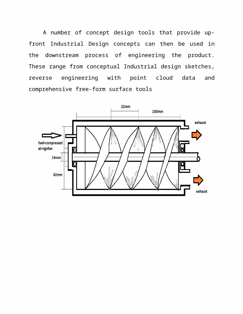
A rotary internal combustion engine including a rotary screw compressor for receiving and compressing a mixture of air and fuel, a rotary positive displacement pump for receiving the compressed air and fuel mixture from the rotary screw compressor and pumping the mixture of compressed air and fuel there through, the pump having igniting means for igniting the mixture of compressed air and fuel inside of the pump, and a rotary screw expander for receiving the ignited mixture of compressed air and fuel and for expanding the volume of the ignited mixture of air and fuel there through.
A rotary internal combustion engine including a rotary screw compressor for receiving and compressing a mixture of air and fuel, a rotary positive displacement pump for receiving the compressed air and fuel mixture from the rotary screw compressor and pumping the mixture of compressed air and fuel there through, the pump having igniting means for igniting the mixture of compressed air and fuel inside of the pump, and a rotary screw expander for receiving the ignited mixture of compressed air and fuel and for expanding the volume of the ignited mixture of air and fuel there through.
Welcome message from author
This document is posted to help you gain knowledge. Please leave a comment to let me know what you think about it! Share it to your friends and learn new things together.
Transcript
DESIGN AND ANALYSIS OF SCREW SHAFT ENGINE
ABSTRACT
This paper presents the development and design considerations of a helical
screw internal combustion engine.
A rotary internal combustion engine including a rotary screw compressor for
receiving and compressing a mixture of air and fuel, a rotary positive displacement
pump for receiving the compressed air and fuel mixture from the rotary screw
compressor and pumping the mixture of compressed air and fuel there through, the
pump having igniting means for igniting the mixture of compressed air and fuel
inside of the pump, and a rotary screw expander for receiving the ignited mixture
of compressed air and fuel and for expanding the volume of the ignited mixture of
air and fuel there through.
Computational Fluid Dynamics (CFD) has been playing an important role in
evaluating and designing various screw machines. Although immense
improvements are achieved in applying CFD procedures for flow prediction and
analysis of screw machines.

CHAPTER 2
INTRODUCTION
This was done simultaneously by Smith in England, and by Ericsson in the
United States.
Both were men of great ability. Each considered himself to be inventor of
the screw propeller. Each took out patents in England, in 1836, and in the United
States, two or three years afterwards. Each patent differed radically from the other;
neither patent, for the general application of the screw propeller, was sustained,
either here or abroad; and neither Smith nor Ericsson patented additional
improvements on the screw propeller.
Each built small screw vessels, in England, that were successfully tried in
1837; Smith's being of six tons burthen, with a wooden screw, driven by a six
horse-power engine, and Ericsson's, named the "Francis B. Ogden," having about
double the tonnage and power.
Each built larger screw vessels that were successfully tried in England in
1839. Smith's vessel, the "Archimedes," being upwards of 200 tons burthen, and
driven by engines designed by Rennie, of 90 horse-power, circumnavigated the
island of Great Britain in May, 1840. Ericsson's vessel, the "Robert F. Stockton,"
smaller, and with less power, was tried in England under steam, and then, in April,
1839, crossed the Atlantic under sail.
Each introduced the screw propeller on merchant vessels in 1840.
Each introduced the screw propeller on war vessels in 1843. Ericsson, on the
"Princeton," and Smith, on the "Rattler."
Both were materially assisted in the introduction of the screw propeller into
use, by the improvements of those who built screw propeller vessels independently
of the patents of either.
The plan of Ericsson's screw propeller on the "Robert F. Stockton" was in
exact accordance with his patent. Smith's plan on the "Archimedes ' varied
essentially from his patent.
Both finally modified their screw propellers, as patented, into the short
screw propellers now in common use.
By the annexed drawing, traced from that of Smith's patent, his screw is
shown with one long blade modeled after the screw of "Archimedes," a screw for
lifting water that differs radically in its action from the screw propeller. The length
of the blade, measured longitudinally on the hub, is shown on his drawing to be
sixteen times greater, in proportion to the diameter of the screw, than that of the
"Rattler," in 1843.
APPLICATION OF A SCREW ROTOR ENGINE AS EXPANSION
DEVICE – BASICS:
The screw engine is a displacement rotary engine which works based on the
Lysholm principle. The Lysholm principle has been economically used in the
1950s for the first time as a screw compressor. The principle is similar to the
workings of piston engines. Both have a closed working chamber, only the one
based on a Lysholm principle changes cyclically instead of oscillating. The
cyclical change thus leads to an in- or decrease of energy content of the fluid in the
chamber. How this process works is further explained in the working principle as
inlet phase, expansion phase and exhaust phase in the section below.
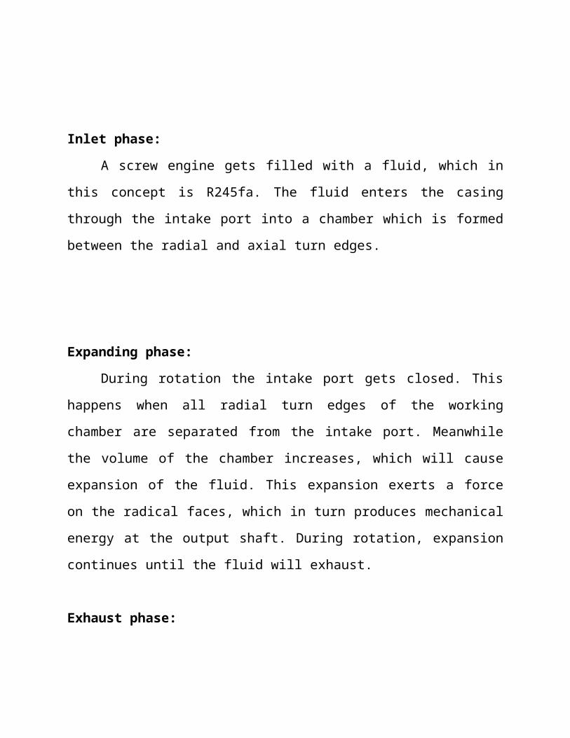
Inlet phase:
A screw engine gets filled with a fluid, which in this concept is R245fa. The
fluid enters the casing through the intake port into a chamber which is formed
between the radial and axial turn edges.
Expanding phase:
During rotation the intake port gets closed. This happens when all radial turn
edges of the working chamber are separated from the intake port. Meanwhile the
volume of the chamber increases, which will cause expansion of the fluid. This
expansion exerts a force on the radical faces, which in turn produces mechanical
energy at the output shaft. During rotation, expansion continues until the fluid will
exhaust.
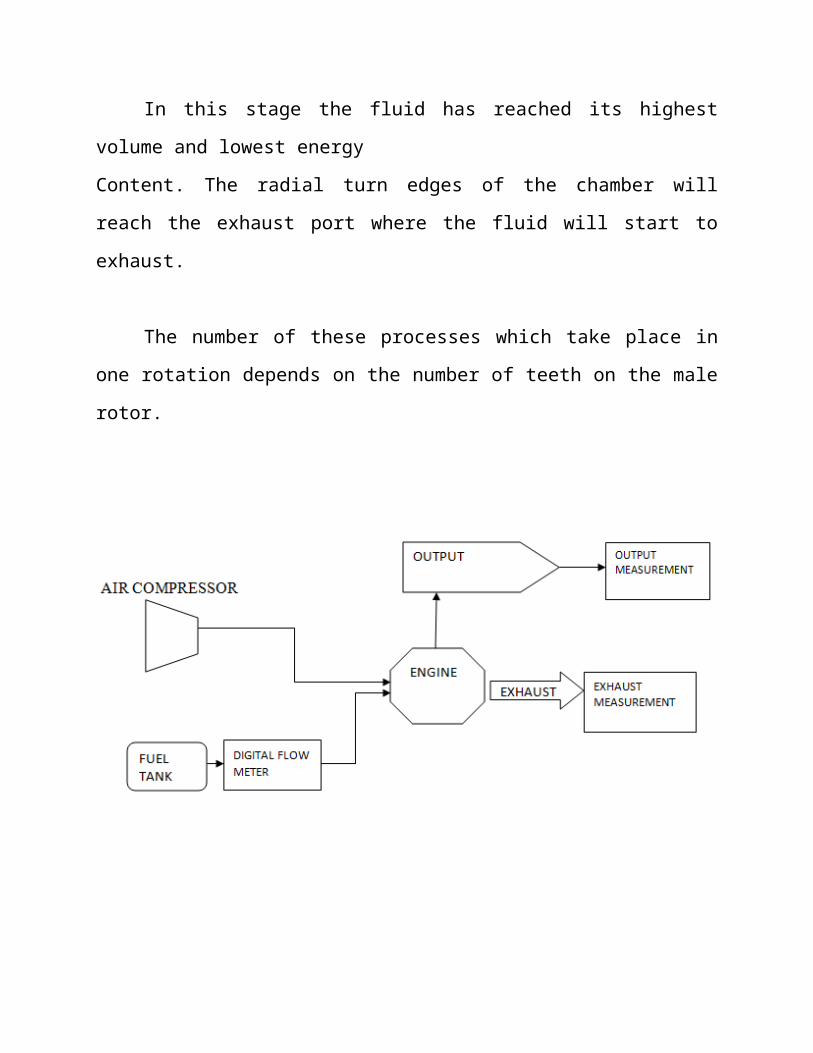
Exhaust phase:
In this stage the fluid has reached its highest volume and lowest energy
Content. The radial turn edges of the chamber will reach the exhaust port where the
fluid will start to exhaust.
The number of these processes which take place in one rotation depends on
the number of teeth on the male rotor.
CHAPTER 3
CAD/CAE
Computer aided design or CAD has very broad meaning and can be defined
as the use of computers in creation, modification, analysis and optimization of a
design. CAE (Computer Aided Engineering) is referred to computers in
Engineering analysis like stress/strain, heat transfer, flow analysis. CAD/CAE is
said to have more potential to radically increase productivity than any development
since electricity. CAD/CAE builds quality form concept to final product. Instead of
bringing in quality control during the final inspection it helps to develop a process
in which quality is there through the life cycle of the product. CAD/CAE can
eliminate the need for prototypes. But it required prototypes can be used to
confirm rather predict performance and other characteristics. CAD/CAE is
employed in numerous industries like manufacturing, automotive, aerospace,
casting, mold making, plastic, electronics and other general-purpose industries.
CAD/CAE systems can be broadly divided into low end, mid end and high-end
systems.
Low-end systems are those systems which do only 2D modeling and with
only little 3D modeling capabilities. According to industry static’s 70-80% of all
mechanical designers still uses 2D CAD applications. This may be mainly due to
the high cost of high-end systems and a lack of expertise.
Mid-end systems are actually similar high-end systems with all their design
capabilities with the difference that they are offered at much lower prices. 3D sold
modeling on the PC is burgeoning because of many reasons like affordable and
powerful hardware, strong sound software that offers windows case of use
shortened design and production cycles and smooth integration with downstream
application. More and more designers and engineers are shifting to mid end
system
High-end CAD/CAE software’s are for the complete modeling, analysis and
manufacturing of products. High-end systems can be visualized as the brain of
concurrent engineering. The design and development of products, which took years
in the passed to complete, is now made in days with the help of high-end
CAD/CAE systems and concurrent engineering
MODELING:
Model is a Representation of an object, a system, or an idea in some form
other than that of the entity itself. Modeling is the process of producing a model; a
model is a representation of the construction and working of some system of
interest. A model is similar to but simpler than the system it represents. One
purpose of a model is to enable the analyst to predict the effect of changes to the
system. On the one hand, a model should be a close approximation to the real
system and incorporate most of its salient features. On the other hand, it should not
be so complex that it is impossible to understand and experiment with it. A good
model is a judicious tradeoff between realism and simplicity. Simulation
practitioners recommend increasing the complexity of a model iteratively. An
important issue in modeling is model validity. Model validation techniques include
simulating the model under known input conditions and comparing model output
with system output. Generally, a model intended for a simulation study is a
mathematical model developed with the help of simulation software.

Software for modeling:
Solid works
Creo
CATIA
Unigraphics, etc
CREO:
Creo Elements/Pro (formerly Pro/ENGINEER), PTC's parametric, integrated
3D CAD/CAM/CAE solution, is used by discrete manufacturers for mechanical
engineering, design and manufacturing.
Created by Dr. Samuel P. Geisberg in the mid-1980s, Pro/ENGINEER was
the industry's first successful rule-based constraint (sometimes called "parametric"
or "variational") 3D CAD modeling system.The parametric modeling approach
uses parameters, dimensions, features, and relationships to capture intended
product behavior and create a recipe which enables design automation and the
optimization of design and product development processes. This design approach
is used by companies whose product strategy is family-based or platform-driven,
where a prescriptive design strategy is fundamental to the success of the design
process by embedding engineering constraints and relationships to quickly
optimize the design, or where the resulting geometry may be complex or based
upon equations. Creo Elements/Pro provides a complete set of design, analysis and
manufacturing capabilities on one, integral, scalable platform. These required
capabilities include Solid Modeling, Surfacing, Rendering, Data Interoperability,
Routed Systems Design, Simulation, Tolerance Analysis, and NC and Tooling
Design.
Like any software it is continually being developed to include new
functionality. The details below aim to outline the scope of capabilities to give an
overview rather than giving specific details on the individual functionality of the
product.
Creo Elements/Pro is a software application within the CAD/CAM/CAE
category, along with other similar products currently on the market.
Creo Elements/Pro is a parametric, feature-based modeling architecture
incorporated into a single database philosophy with advanced rule-based design
capabilities. It provides in-depth control of complex geometry, as exemplified by
the trajpar parameter. The capabilities of the product can be split into the three
main headings of Engineering Design, Analysis and Manufacturing.
Engineering Design
Creo Elements/Pro offers a range of tools to enable the generation of a
complete digital representation of the product being designed. In addition to the
general geometry tools there is also the ability to generate geometry of other
integrated design disciplines such as industrial and standard pipe work and
complete wiring definitions. Tools are also available to support collaborative
development.
A number of concept design tools that provide up-front Industrial Design
concepts can then be used in the downstream process of engineering the product.
These range from conceptual Industrial design sketches, reverse engineering with
point cloud data and comprehensive free-form surface tools
]
Front Cutaway View
ANSYS:
ANSYS is the usually preferred analysis software package because of its
functionality. In this interface, you can apply forces, pressures, torques, etc on the
models and see how the stresses develop.
The ANSYS Workbench platform is the framework upon which the
industry’s broadest and deepest suite of advanced engineering simulation
technology is built. An innovative project schematic view ties together the entire
simulation process, guiding the user through even complex multi physics analyses
with drag-and-drop simplicity. With bi-directional CAD connectivity, an
automated project level update mechanism, pervasive parameter management and
integrated optimization tools, the ANSYS Workbench Platform delivers
unprecedented productivity, enabling simulation driven product development.
If you are good at FEM, you can implement your own mesh generation
techniques (otherwise, ansys will generate the mesh for you; all u have to do is to
apply to conditions over the geometrical model heat sources, forces, etc...)There
are many modules in workbench... static structural analysis, modal analysis
(vibration analysis), thermal analysis etc... If you are interested in this, it won’t
take too long to learn (unlike ansys multi physics), thanks to the modern, user
friendly interface it depends., usually mechanical, civil, aeronautical engineers use
this package. Whether it is good or not depends on your research/work interests.
But whatever it is always remember: anyone can learn ANSYS workbench and use
it to analyze structures! It’s not at all a big deal always remembered to study the
FEA theory very well before you start to use ansys. the reason is that in many real
case scenarios, the ansys always gives some result or the other (never 100%
accurate) and its generally impossible to find out how correct/incorrect the results
are.... but FEA engineers know how to mesh their models and how to configure the
solver in order to get accurate results most of the time! Hence always understand
the FEM before blindly doing the analysis on ansys, it'll help u better interpret the
results..

FINITE ELEMENT ANALYSIS
Introduction of FEA:
It is not possible to obtain Analytical solution for many engineering
problems. At the engineering solution is a mathematical model or expression that
gives the value of the field variable at any location in the body.
For problems involving complex shapes, material properties and
complicated boundary conditions it is difficult, so for many of the practical
problems, and engineer uses numerical methods to solve the problems and that
provides approximate solutions which is also acceptable one. The three methods
are used.
Functional approximation
Functional difference method
Finite element method
FEA and FEM are two of the very popular engineering applications
offered by existing CAD/CAM systems. This is attributed to the fact that the FEM
is perhaps the most popular numerical technique for solving engineering problems.
The method is general enough to handle any complex shape or geometry, any
material properties, any boundary conditions and any loading conditions. The
generality of the FEA method analysis
Requirements to today’s complex engineering systems and designs were
closed form solutions of governing equilibrium equations are generally not
available. In addition, it is an efficient design tool by designers can parametric
design studies by considering various design cases analyzing them and choosing
the optimum design.
The FEM is numerical technique for obtaining approximate solutions
to engineering problems this method is adopted in the industry as a tool to study
stresses in complex air frame structures. The method has gained popularity aimed
of both researches and practioners.
General procedure of the FEA:
The solution of a continuum problem by the finite element
method usually follows an orderly step-by- step processes. The following steps
show in general how the finite element methods.
Discredited the given continuum
Select the solution approximation
Develop element matrices and equations
Assembling the element equations
Solve for the unknown at the nodes
Interpret the results
Modeling Capabilities of Finite Element Software:
There are several such software package available today which
can run on main frame, mini computers as 16 and 32 bit PC, I-DEAS, NASTRAN,
PATRAN, ANSYS, COSMOS, etc.., are some of the well known analysis
packages.
The following list gives the some of the capabilities of finite element
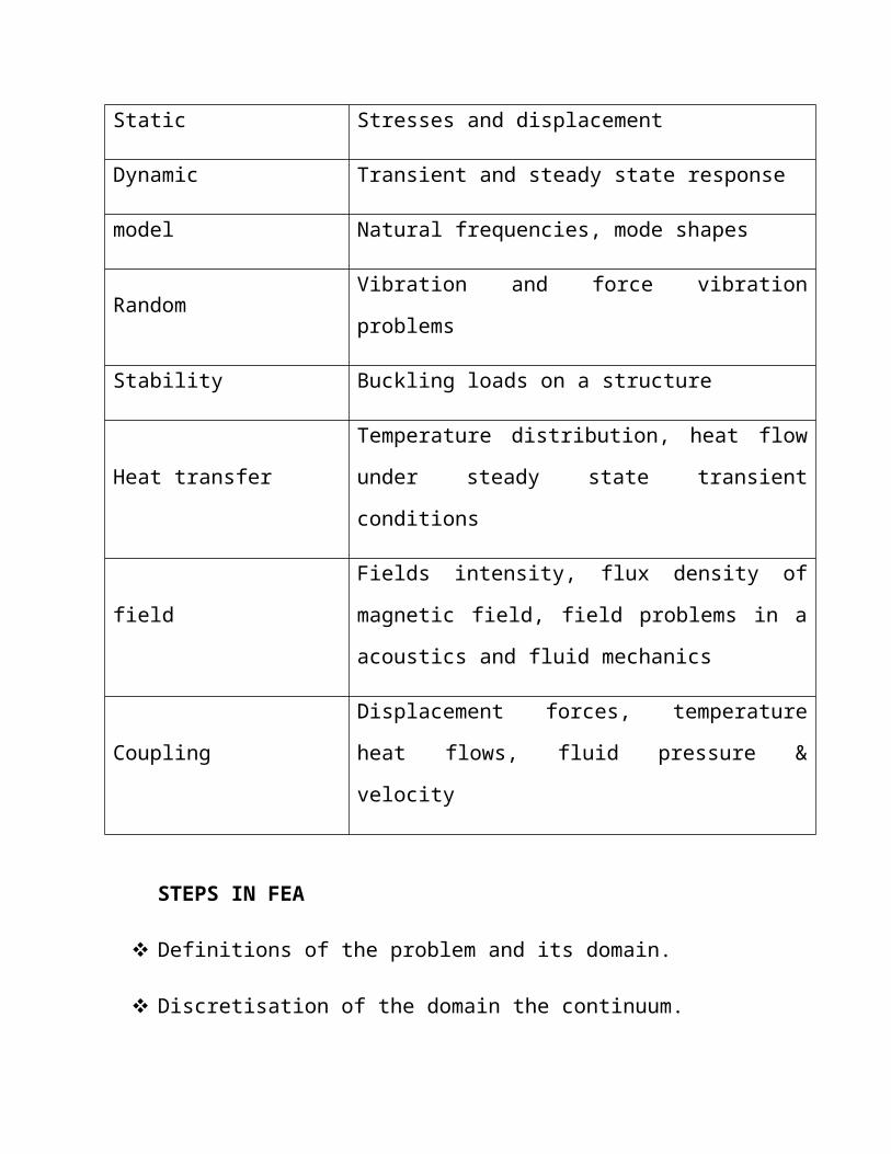
software packages.
TYPES OF ANALYSIS DETERMINATION
Static Stresses and displacement
Dynamic Transient and steady state response
model Natural frequencies, mode shapes
Random Vibration and force vibration problems
Stability Buckling loads on a structure
Heat transferTemperature distribution, heat flow under steady state
transient conditions
fieldFields intensity, flux density of magnetic field, field
problems in a acoustics and fluid mechanics
CouplingDisplacement forces, temperature heat flows, fluid
pressure & velocity
STEPS IN FEA
Definitions of the problem and its domain.
Discretisation of the domain the continuum.
Identification of state variable.
Formulation of the problem.
Establishing coordinate system.
Constructing approximate functions for the elements.
Obtaining element matrix and equation.
Coordinate transformation.
Assembly of element equations.
Introduction of the final set of simultaneous equation.
Interpretations of the results.
BASIC COMPONENTS OF FEA

Pre-processor
Solution
Post processor
General post processor
ADVANTAGES OF FEA
Applicable to any field problem such as heal transfer stress analysis,
magnetic field etc.
There is no matrix restriction.
Approximately it is easily improved by grading the mesh so that more
elements appear where field gradients are high and more resolution is
required.
Compounds that have different behavior and different mathematical
description can be solved.
FEA structure closely resembles closely the actual body or region to be
analyzed.
USES OF FEA
Structural analysis
Heat transfer analysis
Fluid flow analysis
Mass transport
CHAPTER 4
COMPUTATIONAL FLUID DYNAMICS
INTRODUCTION:
A way to have a good working definition of what CFD is to break down the
word. “CFD is the acronym of Computational Fluid Dynamics. Computational
means having to do with mathematics, computation and Fluid Dynamics refers to
the dynamics of things that flow.”
So, CFD is a computational technology that enables you to study things that
flow. CFD not only predicts fluid flow behavior, but also the transfer of heat, mass,
phase change, chemical reaction, mechanical movement and stress or deformation
of related solid structures.
Computational Fluid Dynamics or simply CFD is concerned with obtaining
numerical solution to fluid flow problems by using computers. The advent of high-
speed and large-memory computers has enabled CFD to obtain solutions to many
flow problems including those that are compressible or incompressible, laminar or
turbulent, chemically reacting or non-reacting. Computational Fluid Dynamics
(CFD) is the science of predicting fluid flow, heat transfer, mass transfer, chemical
reactions, and related phenomena by solving the mathematical equations which
govern these processes using computational methods.
CFD is the art of replacing the differential equation governing the Fluid
Flow, with a set of algebraic equations (the process is called discretization), which
in turn can be solved with the aid of a digital computer to get an approximate
solution. The well known discretization methods used in CFD are, Finite Volume
Method (FVM), Finite Element Method (FEM), and Boundary Element Method
(BEM).
THE BENEFITS OF CFD:
Insight: There are many devices and systems that are very difficult to
prototype. Often, CFD analysis shows parts of the system or phenomena happening
within the system that would not otherwise be visible through any other means.
CFD gives a means of visualizing and an enhanced understanding of the various
designs.
Foresight: Because CFD is a tool for predicting what will happen
under a given set of circumstances, it can answer many ‘what if?’ questions very
quickly. We give it variables. It gives us outcomes. In a short time, we can predict
how the design will perform, and many variations may be tested until you arrive at
an optimal result. All of this is done before physical prototyping and testing. The
foresight we gain from CFD helps us to design better and faster.
Efficiency: Better and faster design or analysis leads to shorter design
cycles. Time and money are saved. Products get to market faster. Equipment
improvements are built and installed with minimal downtime. CFD is a tool for
compressing the design and development cycle.
APPLICATIONS OF CFD:
CFD is interdisciplinary cutting across fields of aerospace, mechanical, civil,
chemical, electrical engineering as well as physics and chemistry. CFD has been
widely used in industry in the past decade. It is certainly fun for fluids enthusiasts,
but where exactly can CFD be applied - the following are areas of applications of
CFD to date.
Automobile and Engine
o Aerodynamics, Engines, Turbochargers, Intake/Exhaust
Heating/Cooling Systems, Brakes etc.
Industrial Manufacturing
o Aerospace, Aerodynamics. Gas Turbines, Rockets etc.
Mechanical
o Pumps, Compressors, Heat Exchangers, Furnaces, Nuclear Reactors
etc.
Chemical
o Mixers (multiphase), Chemical Reactors, Separators, Boilers,
Condensers etc.
Environmental Engineering
o Weather prediction, River and Tidal flows, Wind and Water-borne
pollution, Fire and Smoke spread, Wind loading etc.
Physiological

o Cardiovascular flows (Heart, major vessels), Flow in Lungs and
breathing passages etc.
Naval Architecture
o Ship building etc.
METHODOLOGY& VARIOUS STEPS:
In this work, first of all a generic model of the passenger car is prepared in
the SOLIDWORKS software and this generic model is import into the ANSYS
FLUENT to do the simulation of the coefficient of drag and coefficient of lift in
the wind tunnel which is generated in the design module of the ANSYS FLUENT.
After this the meshing is generated on the surface of the passenger car.
Aerodynamic evaluation of air flow over an object can be performed using
analytical method or CFD approach. On one hand, analytical method of solving air
flow over an object can be done only for simple flows over simple geometries like
laminar flow over a flat plate. If air flow gets complex as in flows over a bluff
body, the flow becomes turbulent and it is impossible to solve Navier- Stokes and
continuity equations analytically. On the other hand, obtaining direct numerical
solution of Navier-stoke equation is not yet possible even with modern day
computers. In order to come up with reasonable solution, a time averaged Navier-
Stokes equation is being used (Reynolds Averaged Navier-Stokes Equations –
RANS equations) together with turbulent models to resolve the issue involving
Reynolds Stress resulting from the time averaging process. In present work the k-e
turbulence model with non-equilibrium wall function is selected to analyze the
flow over the generic passenger car model. This k-e turbulence model is very
robust, having reasonable computational turnaround time, and widely used by the
auto industry.
STEPS OF ANALYSIS:
Select the models of vehicle upon which add on devices are to be used.
Formation of Base Line Model: Designing of model in solid works with
proper dimensions & parameters.
Baseline passenger car CFD method and setup: Apply the boundary
conditions.
Generate the wind tunnel for simulation.
Simulation & Testing of base line passenger car for drag coefficient and lift
coefficient.
Simulation & Testing of passenger car with tail plates for drag coefficient &
lift coefficient.
Impact of add on device on fuel economy of Passenger car.
FORMATION OF BASE LINE MODEL:
The base line model of generic passenger car is designed in Solid Works.
Figure 1 show the generic passenger car used in the present CFD simulation. The
full size generic passenger car is 4389mm long, 1350mm wide, 1375mm high.
Then after, this model has been analyzed for drag coefficient and forces under the
ANSYS-14.0 (FULENT) module and values of drag coefficient lift coefficient

CHAPTER 5
PRINCIPLE OF THE SCREW-TYPE ENGINE TECHNOLOGY:
The screw-type engine is a displacement rotary engine. Similar to piston
engines, displacement-type engines are characterized by a closed working
chamber. The volume of the working chamber changes cyclically, which leads to a
decrease of the energy content of the fluid in the chamber. The main parts of a
screw-type engine are the male rotor, the female rotor and a casing, which together
form a V-shaped working chamber whose volume depends solely on the angle of
rotation. The steam enters the casing through the intake port in the passage formed
between the tips of the rotor teeth. During rotation the volume of the chamber
increases. Intake is finished when the rotor faces pass the guiding edges and the
chamber is separated from the intake port. At this stage steam expansion starts and
mechanical power is produced at the output shaft. During expansion the volume of
the chamber continues to increase, whereas the energy content of the fluid
decreases. This process continues until the exhaust process starts and the steam is
extruded. It leaves the machine through the exhaust port. How often this process
takes place during one rotation of the male rotor depends on the number of teeth on
the male rotor.
The screw-type engine is a very compact machine with a long life time and low
maintenance costs.
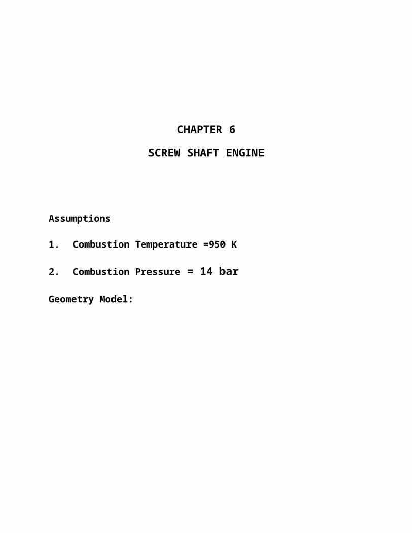
CHAPTER 6
SCREW SHAFT ENGINE
Assumptions
1. Combustion Temperature =950 K
2. Combustion Pressure = 14 bar
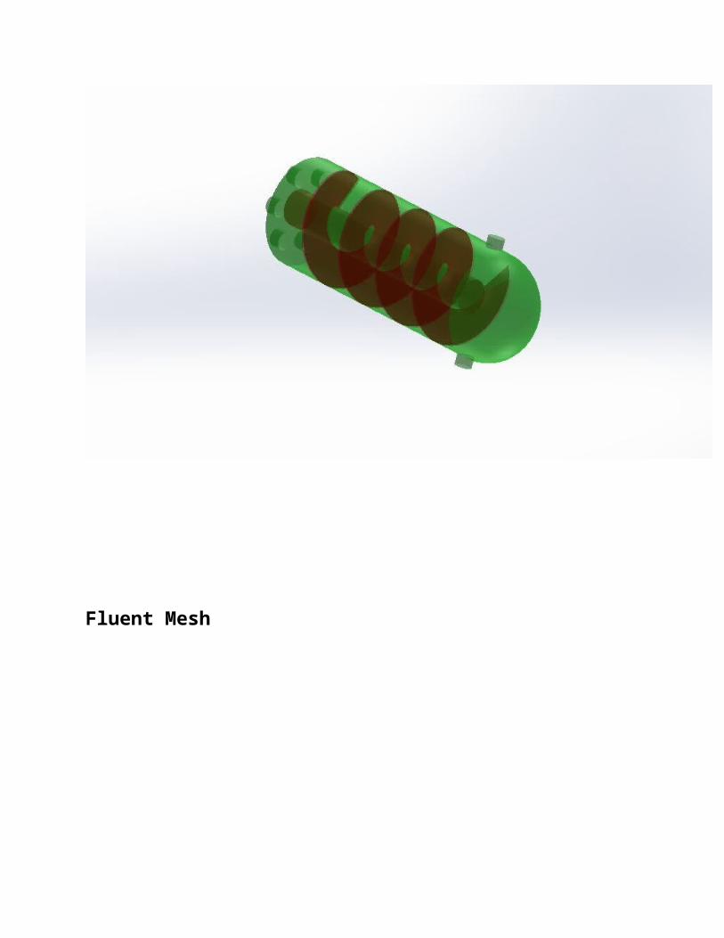
Geometry Model:
Fluent Mesh

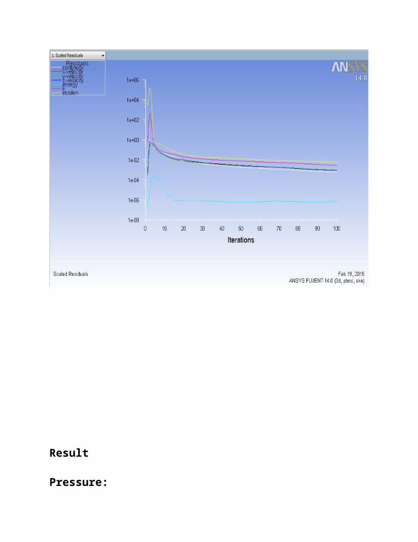
Iteration
Result
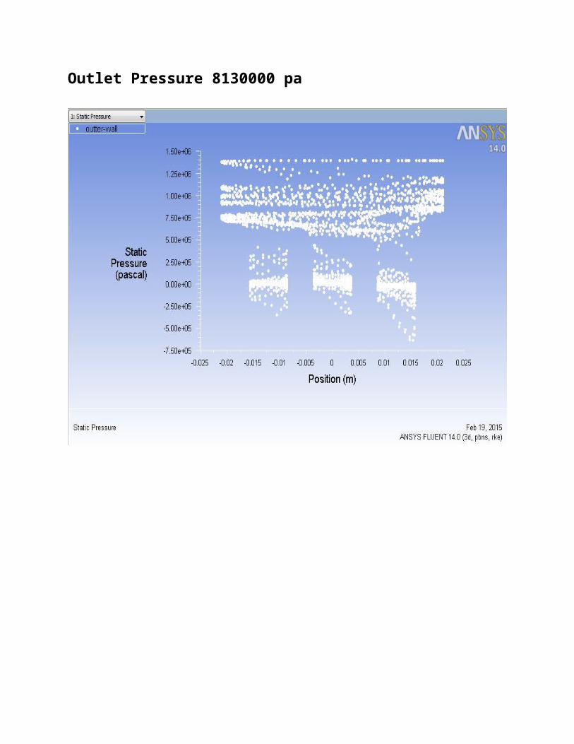
Pressure:
Outlet Pressure 8130000 pa

Temperature

Outlet Temperature 960 k
Velocity
Outlet Velocity 820 m/s

CONCLUSION
Outlet Pressure =8130000 pa
Outlet Temperature =960 k
Outlet Velocity =820 m/s
Advantages of the screw-type engine process:
Screw-type steam engines for small-scale biomass CHP applications have a
number of advantages compared to conventional steam turbines and steam engines:
Comparatively high electric efficiency for small-scale CHP units (< 1,000
kWel)
The screw-type engine has a very good partial-load efficiency over a wide
range of load conditions
Load fluctuations between 30 and 100 % of nominal electric power
production are no problem
The screw-type engine is insensitive to steam quality fluctuations. Even
water droplets in steam, which can occur in a simple boiler due to
malfunction or changes of fuel quality, do not cause any problems in screw-
type engines
The steam cycle and the oil cycle are completely separated by an air-lock
system
The fully automatic operation and easy handling saves staff costs
The screw-type engine is a very compact machine and causes low
maintenance costs
Control system and safety equipment:
The screw-type steam engine works in grid connected operation. Plant
operation and start up are controlled fully automatically by an electronic control
system and do not require additional staff.
To make sure that the oil in the bearings and the synchronising gear is
separated from the steam in the working chamber, the labyrinth packing of the
screw-type engine is designed in a way that fluids can be drained or supplied
through various components (seals - connections). To separate the oil section from
the water section, air is injected under slight pressure. Some parts of the seal are
connected in order to make sure that no air can enter the working chamber if there
is a vacuum in the condenser.

CHAPTER 7
CONCLUSION
In this paper, CFD analysis has been done to understand flow disturbance
caused by the screw engine in an internal combustion engine.
A full multivariable optimization of screw expander geometry
and operating conditions has been performed to establish the
most efficient expander design for a given duty.

CHAPTER 8
REFERENCE
Vimmr J, Ondrey F, 2006, Numerical Simulation of Leakage Flow Between
Moving Rotor and Housing of Screw Compressor, Proceedings of the Conference
Modelowanyie Inzynierskie, ISNN 1896-771X, 32, s. 461-468, Gliwice 2006.
Taniguchi, H.; Kudo, K.; Giedt, W. H.; Park, I.; Kumazawa, S.Analytical
and Experimental Investigation of Two-Phase Flow Screw Expanders for Power
Generation. J. Eng. Gas Turbines Power 1988,110, 628–635.
Ng, K. C.; Bong, T. Y.; Lim, T. B. A Thermodynamic Model for the
Analysis of Screw Expander Performance. Heat Recov. Sys. CHP 1990,10, 119–
133.
Winterbone DE, Pearson RJ (2000). Theory of engine manifold design -
Wave action methods for I.C. Engines. Professional Engineering Publishing
Limited, London and Buery St Edmunds, U.K.
Calculating the Trajectories of Triboelectrically charged particles using
Discrete Element Modelling (DEM), M Hogue, C Calle, D Curry, P Weitzman,
ESA 2007 Annual Conference.
Related Documents