International Journal of Scientific Engineering and Research (IJSER) ISSN (Online): 2347-3878 Index Copernicus Value (2015): 62.86 | Impact Factor (2015): 3.791 Volume 5 Issue 6, June 2017 www.ijser.in Licensed Under Creative Commons Attribution CC BY Design and Analysis of Satellite Subsystem Supporting Structure Ranganath N 1 , Dr. Panchakshari H V 2 , Dr. A Ramesh 3 , Hareesh A 4 Mechanical Department, KSIT, Bengaluru, Mechanical Department, RRIT, BITS Institute of Technology, Hindupur, Department of Mechanical Engg, KSSEM Abstract: In the era of scientific and technological advancements continuous improvements of the existing systems is becoming the order of the day. More emphasis is given towards the R&D and adoption of latest trends. The application of Aluminum materials in the field of space technology has proved the performance improvements in terms of reduced mass and increased stiffness. Design and Analysis of satellite support system using aluminium is taken up for study. The main objective is to design a support structure for meeting the given constraints of geometry and stiffness with minimum mass. Various analyses were performed to select the final configuration. Free vibration analysis was done to assess interaction between the subsystem and supporting structure. Sensitivity analyses were performed by varying the design parameters of the structure. Linear static analysis was performed to study the response of structure for static loads. Buckling analysis was performed to study the critical loads of support structure. The design analysis is carried out using Design and Analysis software I-DEAS. Keywords: Sub system, Vibration, Buckling, Static, FE model, Analysis 1. Introduction Increased accuracy of payloads, the on-orbit structural dynamic behavior of spacecraft is increasingly influencing the design and performance of spacecraft. Present work is on the design of a satellite subsystem support structure assembly for mass reduction with safe operating conditions. The forces imparted to the spacecraft are important for sensitive instruments. In this report a safe configuration is suggested with significant achievement in mass reduction. Normal mode analysis and sensitivity analysis were performed to select an optimized design configuration. The requirements of such a support structure are high stiffness, low weight and high strength. The structure is connected to the deck of the satellite and it carries subsystems mounted on it. The top surface of the bracket is connected to the deck of the satellite. As materials used for the spacecraft application must be lightweight and also retain their stiffness throughout the spacecraft mission in orbit. Subsystem support structure is basically designed for stiffness requirements. While keeping stiffness as the design criteria, the structure will be checked to withstand static and dynamic loads arising during launch phase. Specification of subsystem considered for Design: Sub system mass and Inertia. Mass : 1kg Ixx= 5384.81kg-mm 2 , Iyy= 4661.9kg-mm 2 , Izz= 1004.72kg-mm 2 C.G location=20mm above the subsystem interface. Figure 1: Representation of sub system First natural frequency > 70 Hz: To avoid coupling between bracket and rest of the spacecraft. Static analysis: 20g load taken in X, Y and Z directions independently. Buckling analysis: 20g load taken in X, Y and Z directions independently. 2. Problem Description The main objective of the structural design is to achieve the minimum mass structure, which will satisfy the stiffness and strength requirements. Hence, optimum configuration, newer technological achievements have to be incorporated to attain minimum mass, which at the same time satisfy all the basic requirements. Material Properties Material used for subsystem support structure is AA-2024. Whose properties are given below: Material E (N\m 2 ) ΰ G (N\m 2 ) Density(kg\m 3 ) Aluminium 70E+9 0.30 26.8E+9 2800 E = Young’s Modulus of the Aluminum υ = Poison’s Ratio G = shear Modulus of the Aluminum Paper ID: IJSER151544 65 of 70

Welcome message from author
This document is posted to help you gain knowledge. Please leave a comment to let me know what you think about it! Share it to your friends and learn new things together.
Transcript
International Journal of Scientific Engineering and Research (IJSER) ISSN (Online): 2347-3878
Index Copernicus Value (2015): 62.86 | Impact Factor (2015): 3.791
Volume 5 Issue 6, June 2017
www.ijser.in Licensed Under Creative Commons Attribution CC BY
Design and Analysis of Satellite Subsystem
Supporting Structure
Ranganath N1, Dr. Panchakshari H V
2, Dr. A Ramesh
3, Hareesh A
4
Mechanical Department, KSIT, Bengaluru, Mechanical Department, RRIT, BITS Institute of Technology, Hindupur, Department of
Mechanical Engg, KSSEM
Abstract: In the era of scientific and technological advancements continuous improvements of the existing systems is becoming the
order of the day. More emphasis is given towards the R&D and adoption of latest trends. The application of Aluminum materials in the
field of space technology has proved the performance improvements in terms of reduced mass and increased stiffness. Design and
Analysis of satellite support system using aluminium is taken up for study. The main objective is to design a support structure for
meeting the given constraints of geometry and stiffness with minimum mass. Various analyses were performed to select the final
configuration. Free vibration analysis was done to assess interaction between the subsystem and supporting structure. Sensitivity
analyses were performed by varying the design parameters of the structure. Linear static analysis was performed to study the response of
structure for static loads. Buckling analysis was performed to study the critical loads of support structure. The design analysis is carried
out using Design and Analysis software I-DEAS.
Keywords: Sub system, Vibration, Buckling, Static, FE model, Analysis
1. Introduction
Increased accuracy of payloads, the on-orbit structural
dynamic behavior of spacecraft is increasingly influencing
the design and performance of spacecraft. Present work is on
the design of a satellite subsystem support structure assembly
for mass reduction with safe operating conditions. The forces
imparted to the spacecraft are important for sensitive
instruments. In this report a safe configuration is suggested
with significant achievement in mass reduction. Normal
mode analysis and sensitivity analysis were performed to
select an optimized design configuration. The requirements
of such a support structure are high stiffness, low weight and
high strength.
The structure is connected to the deck of the satellite and it
carries subsystems mounted on it. The top surface of the
bracket is connected to the deck of the satellite.
As materials used for the spacecraft application must be
lightweight and also retain their stiffness throughout the
spacecraft mission in orbit. Subsystem support structure is
basically designed for stiffness requirements. While keeping
stiffness as the design criteria, the structure will be checked
to withstand static and dynamic loads arising during launch
phase.
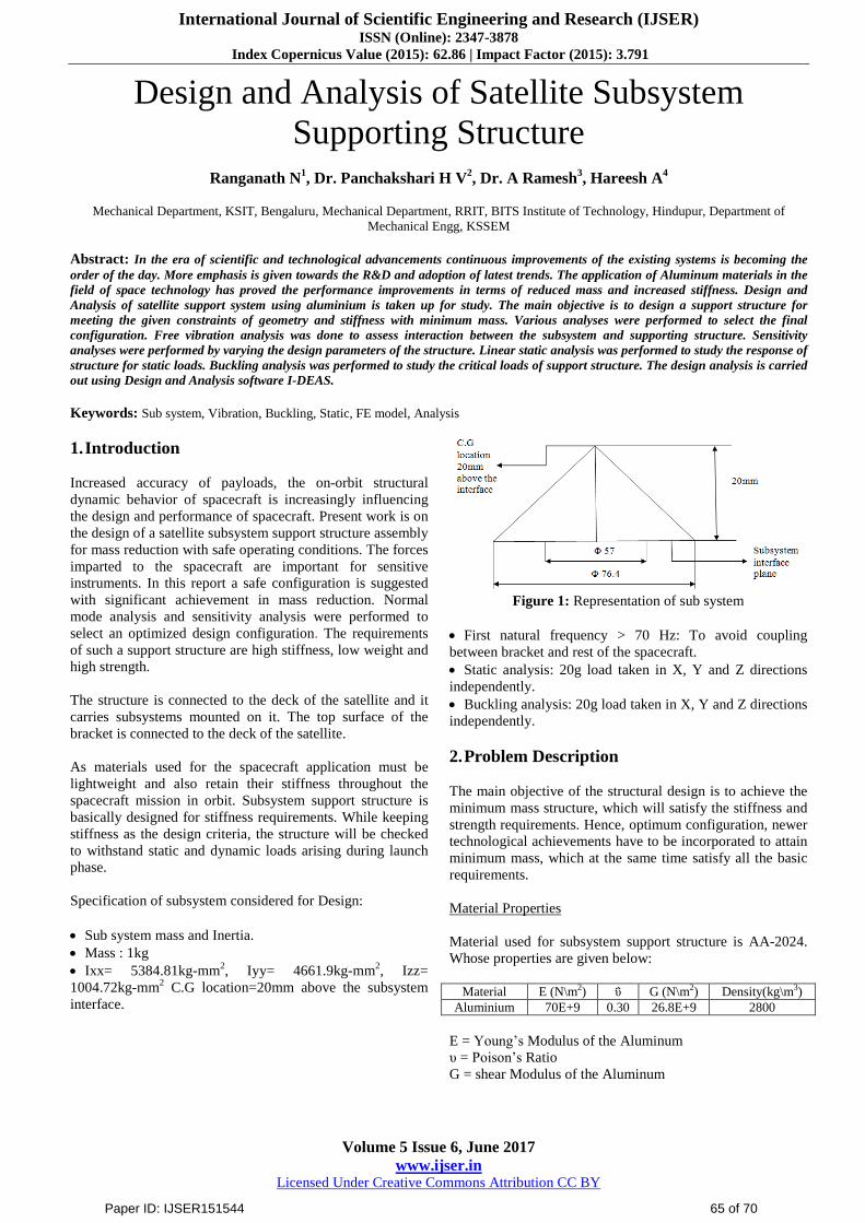
Specification of subsystem considered for Design:
Sub system mass and Inertia.
Mass : 1kg
Ixx= 5384.81kg-mm2, Iyy= 4661.9kg-mm
2, Izz=
1004.72kg-mm2 C.G location=20mm above the subsystem
interface.
Figure 1: Representation of sub system
First natural frequency > 70 Hz: To avoid coupling
between bracket and rest of the spacecraft.
Static analysis: 20g load taken in X, Y and Z directions
independently.
Buckling analysis: 20g load taken in X, Y and Z directions
independently.
2. Problem Description
The main objective of the structural design is to achieve the
minimum mass structure, which will satisfy the stiffness and
strength requirements. Hence, optimum configuration, newer
technological achievements have to be incorporated to attain
minimum mass, which at the same time satisfy all the basic
requirements.
Material Properties
Material used for subsystem support structure is AA-2024.
Whose properties are given below:
Material E (N\m2) ΰ G (N\m2) Density(kg\m3)
Aluminium 70E+9 0.30 26.8E+9 2800
E = Young’s Modulus of the Aluminum
υ = Poison’s Ratio
G = shear Modulus of the Aluminum
Paper ID: IJSER151544 65 of 70
International Journal of Scientific Engineering and Research (IJSER) ISSN (Online): 2347-3878
Index Copernicus Value (2015): 62.86 | Impact Factor (2015): 3.791
Volume 5 Issue 6, June 2017
www.ijser.in Licensed Under Creative Commons Attribution CC BY
3. Steps in Analysis
The following types of analysis are carried out:
1. Free Vibration Analysis
2. Static Analysis
3. Buckling analysis
1. Free vibration analysis ( Eigenvalue analysis)
For a structural system with a total DOF of N, the stiffness
matrix K and mass matrix M have a dimension of N ×N. In
this technique, first solve the homogenous equation. The
homogeneous equation is by considering the case of F = 0,
therefore it is also called free vibration analysis, as the
system is free of external forces. For a solid or structure that
undergoes a free vibration, the discretized system equation
becomes.
KD +MD¨ = 0 (Eq.2.1)
This solution for the free vibration problem can be assumed
as
D = φ exp (iωt) (Eq.2.2)
Where φ is the amplitude of the nodal displacement, ω is the
frequency of the free vibration, and t is the time.
By substituting Eq. (2.2) into Eq. (2.1), we obtain
[K − ω2M] φ = 0 (Eq.2.3)
or
[K − λM] φ = 0 (Eq.2.4)
where
λ = ω2 (Eq.2.5)
Equation (2.3) (or (2.4)) is called the eigenvalues equation.
To have a non-zero solution for φ, the determinate of the
matrix must vanish:
det [K − λM] = |K − λM| = 0 (Eq.2.6)
The expansion of the above equation will lead to a
polynomial of λ of order N. This polynomial equation will
have N roots, λ1, λ2. . . λN, called eigenvalues, which relate to
the natural frequency of the system by Eq. (2.3).
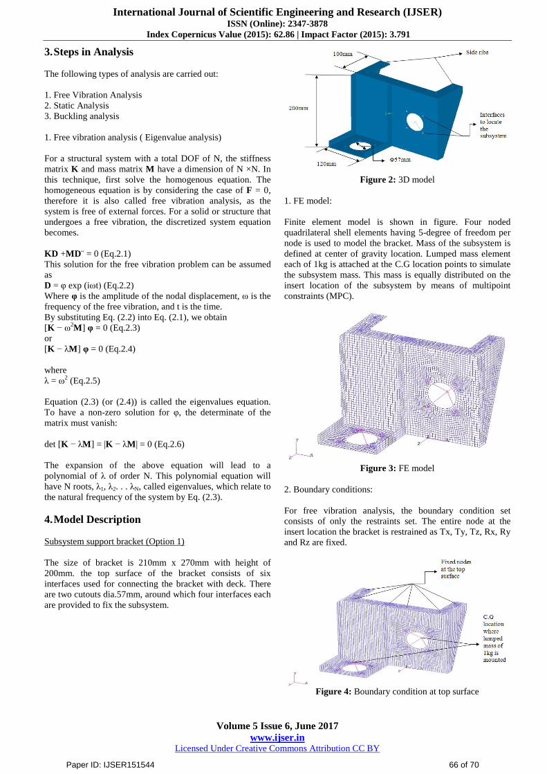
4. Model Description
Subsystem support bracket (Option 1)
The size of bracket is 210mm x 270mm with height of
200mm. the top surface of the bracket consists of six
interfaces used for connecting the bracket with deck. There
are two cutouts dia.57mm, around which four interfaces each
are provided to fix the subsystem.
Figure 2: 3D model
1. FE model:
Finite element model is shown in figure. Four noded
quadrilateral shell elements having 5-degree of freedom per
node is used to model the bracket. Mass of the subsystem is
defined at center of gravity location. Lumped mass element
each of 1kg is attached at the C.G location points to simulate
the subsystem mass. This mass is equally distributed on the
insert location of the subsystem by means of multipoint
constraints (MPC).
Figure 3: FE model
2. Boundary conditions:
For free vibration analysis, the boundary condition set
consists of only the restraints set. The entire node at the
insert location the bracket is restrained as Tx, Ty, Tz, Rx, Ry
and Rz are fixed.
Figure 4: Boundary condition at top surface
Paper ID: IJSER151544 66 of 70

International Journal of Scientific Engineering and Research (IJSER) ISSN (Online): 2347-3878
Index Copernicus Value (2015): 62.86 | Impact Factor (2015): 3.791
Volume 5 Issue 6, June 2017
www.ijser.in Licensed Under Creative Commons Attribution CC BY
3. Design parametric study:
The design parameter like thickness of the model was varied
in order to select a suitable configuration. The variation of
frequency with change in thickness for the model of
configuration 1 is as shown below:
Graph 1: Thickness vs. Frequency
As it is observed from the graph 1 the change in the
thickness of the bracket results in the change of the natural
frequency of the structure. Since, the required frequency of
70 Hz is achieved with 4mm thicknesses that results in 1.2kg
mass of the bracket. So, in order to minimize the mass for the
desired frequency, design modification in the bracket is
required. The mode shape of first and second natural
frequencies with 2mm shell thickness is shown in fig below.
Figure 5: First mode shape (29.88Hz)
Figure 6: Second mode shape (63.95Hz)
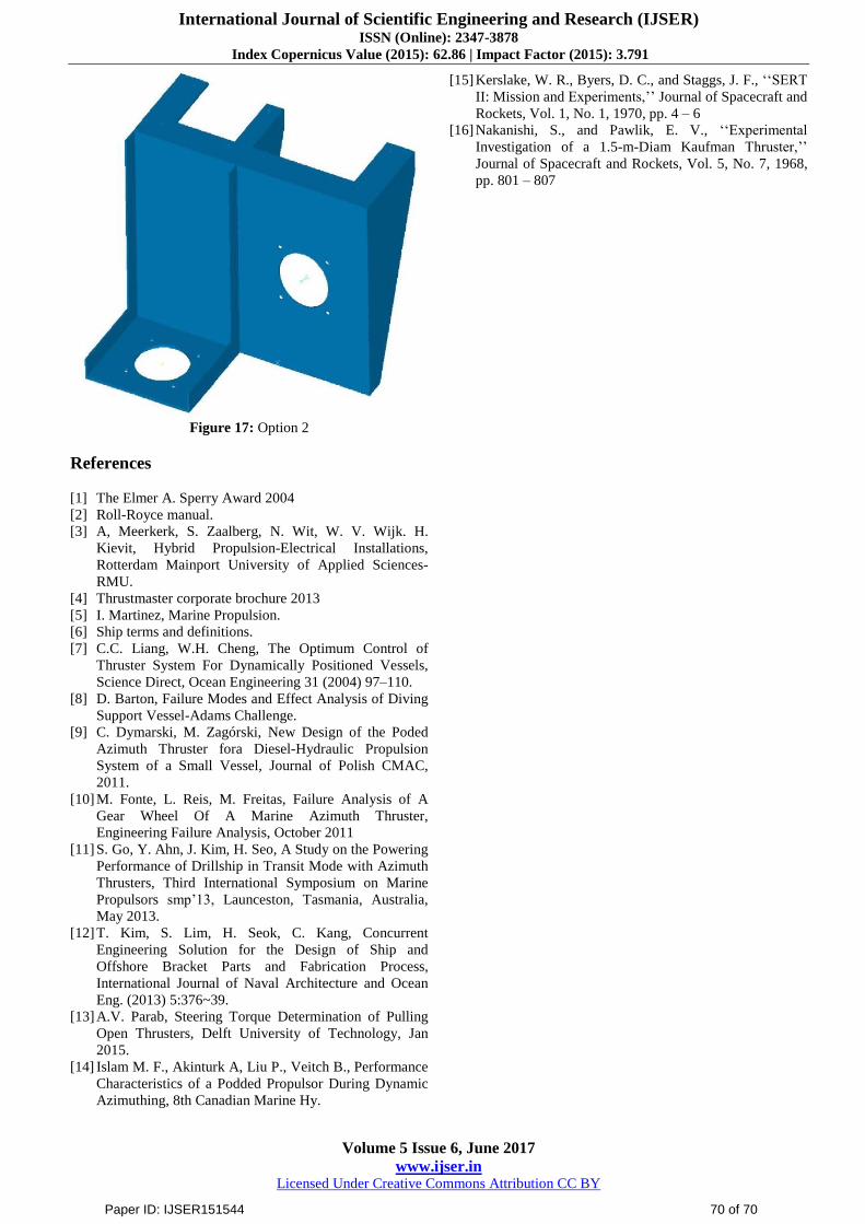
Modified Subsystem Support Bracket (Option 2)
In the modified bracket one additional rib is provided at the
mid with suitable interfaces. All other major dimensions are
same as previous bracket.
Figure 7: 3D model
1. FE model:
Finite element model is shown in figure 8. Four noded
quadrilateral shell elements having 5- degree of freedom per
node is used to model the bracket. Mass of the subsystem is
defined at C.G location. Lumped mass element each of 1kg
is attached at the C.G location points to simulate the
subsystem mass. This mass is equally distributed on the
insert location of the subsystem by means of multipoint
constraints (MPC).
Figure 8: FE model
2. Boundary condition:
For free vibration analysis the boundary condition set
consists of only the restraints set.
Figure 9: Boundary conditions at top surface
Paper ID: IJSER151544 67 of 70

International Journal of Scientific Engineering and Research (IJSER) ISSN (Online): 2347-3878
Index Copernicus Value (2015): 62.86 | Impact Factor (2015): 3.791
Volume 5 Issue 6, June 2017
www.ijser.in Licensed Under Creative Commons Attribution CC BY
4. Design parametric Study:
The design parameter like thickness of the model was varied
in order to select a suitable configuration. The variation of
frequency with change in thickness for the designed thruster
bracket is as shown below:
Graph 2: Thickness vs Frequency
As it is observed from the graph that change in the thickness
results in the change of the natural frequency of the structure.
The required frequency of 70 Hz is achieved with 2 mm
thickness resulting mass of 0.697kg against 1.2kg as
compared to the previous bracket. So, this model satisfies the
stiffness criterion with minimum mass.
5. Static Analysis
In case of static structural analysis the loads are assumed to
be applied slowly and the model is constrained to prevent
rigid body motion. That is, Static equilibrium exists for the
model.
Model Description:
Linear static analysis was carried out to compute the
response of structure for 20g load in X, Y and Z directions
independently. I-DEAS linear static analysis was used for
required purpose. The load entry was used to define the
direction and magnitude of a gravity vector in Global
Coordinate System.
6. Results and Discussion
Von mises stresses and interface forces are calculated for
20g load in X, Y, Z directions independently and results are
given in table 4.1 and 4.2
Table 1: von mises stresses
load
Von mises
stress
(MPA)
Factor of
safety
(FOS)
Margin of
safety
(MOS=FOS-1)
20g-X
direction 212 1.27 0.27
20g-Y
direction 138 1.95 0.95
20g-z
direction 212 1.27 0.27
Table 2: Check for interface forces
Load Force in Kgf
20g-X direction 18.8
20g-Y direction 10.6
20g-Z direction 36.2
Figure 10: von mises stress for 20g load in X direction
Figure 11: von mises stress for 20g load in Y direction
Figure 12: von mises stress for 20g load in Z direction
7. Buckling Analysis
In linear static analysis a structure is normally considered to
be in a state of stable equilibriums the load is removed, the
structure is assumed to return to its original position.
However, under certain combination of loading, the structure
may become unstable. When this loading is reached, the
Paper ID: IJSER151544 68 of 70
International Journal of Scientific Engineering and Research (IJSER) ISSN (Online): 2347-3878
Index Copernicus Value (2015): 62.86 | Impact Factor (2015): 3.791
Volume 5 Issue 6, June 2017
www.ijser.in Licensed Under Creative Commons Attribution CC BY
structure continues to deflect without increase in magnitude
of loading. In this case, the structure has actually buckled or
has become unstable. Present study is performed for 20g
forces in X, Y and Z direction.
Model Description:
Linear buckling analysis was carried out to compute the
buckling failure of the structure for 20g force in X, Y and Z
directions respectively. The fixed boundary condition was
assumed at the connecting holes on the top surface of the
bracket. I-DEAS Linear buckling analysis was used for the
required purpose.
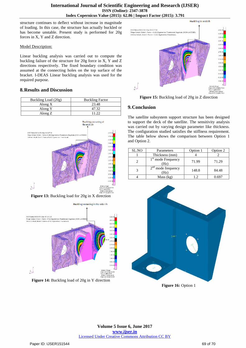
8. Results and Discussion
Buckling Load (20g) Buckling Factor
Along X 23.48
Along Y 47.32
Along Z 11.22
Figure 13: Buckling load for 20g in X direction
Figure 14: Buckling load of 20g in Y direction
Figure 15: Buckling load of 20g in Z direction
9. Conclusion
The satellite subsystem support structure has been designed
to support the deck of the satellite. The sensitivity analysis
was carried out by varying design parameter like thickness.
The configuration studied satisfies the stiffness requirement.
The table below shows the comparison between Option 1
and Option 2.
SL.NO Parameters Option 1 Option 2
1 Thickness (mm) 4 2
2 1st mode Frequency
(Hz) 71.99 71.29
3 2nd mode frequency
(Hz) 148.8 84.48
4 Mass (kg) 1.2 0.697
Figure 16: Option 1
Paper ID: IJSER151544 69 of 70
International Journal of Scientific Engineering and Research (IJSER) ISSN (Online): 2347-3878
Index Copernicus Value (2015): 62.86 | Impact Factor (2015): 3.791
Volume 5 Issue 6, June 2017
www.ijser.in Licensed Under Creative Commons Attribution CC BY
Figure 17: Option 2
References
[1] The Elmer A. Sperry Award 2004
[2] Roll-Royce manual.
[3] A, Meerkerk, S. Zaalberg, N. Wit, W. V. Wijk. H.
Kievit, Hybrid Propulsion-Electrical Installations,
Rotterdam Mainport University of Applied Sciences-
RMU.
[4] Thrustmaster corporate brochure 2013
[5] I. Martinez, Marine Propulsion.
[6] Ship terms and definitions.
[7] C.C. Liang, W.H. Cheng, The Optimum Control of
Thruster System For Dynamically Positioned Vessels,
Science Direct, Ocean Engineering 31 (2004) 97–110.
[8] D. Barton, Failure Modes and Effect Analysis of Diving
Support Vessel-Adams Challenge.
[9] C. Dymarski, M. Zagórski, New Design of the Poded
Azimuth Thruster fora Diesel-Hydraulic Propulsion
System of a Small Vessel, Journal of Polish CMAC,
2011.
[10] M. Fonte, L. Reis, M. Freitas, Failure Analysis of A
Gear Wheel Of A Marine Azimuth Thruster,
Engineering Failure Analysis, October 2011
[11] S. Go, Y. Ahn, J. Kim, H. Seo, A Study on the Powering
Performance of Drillship in Transit Mode with Azimuth
Thrusters, Third International Symposium on Marine
Propulsors smp’13, Launceston, Tasmania, Australia,
May 2013.
[12] T. Kim, S. Lim, H. Seok, C. Kang, Concurrent
Engineering Solution for the Design of Ship and
Offshore Bracket Parts and Fabrication Process,
International Journal of Naval Architecture and Ocean
Eng. (2013) 5:376~39.
[13] A.V. Parab, Steering Torque Determination of Pulling
Open Thrusters, Delft University of Technology, Jan
2015.
[14] Islam M. F., Akinturk A, Liu P., Veitch B., Performance
Characteristics of a Podded Propulsor During Dynamic
Azimuthing, 8th Canadian Marine Hy.
[15] Kerslake, W. R., Byers, D. C., and Staggs, J. F., ‘‘SERT
II: Mission and Experiments,’’ Journal of Spacecraft and
Rockets, Vol. 1, No. 1, 1970, pp. 4 – 6
[16] Nakanishi, S., and Pawlik, E. V., ‘‘Experimental
Investigation of a 1.5-m-Diam Kaufman Thruster,’’
Journal of Spacecraft and Rockets, Vol. 5, No. 7, 1968,
pp. 801 – 807
Paper ID: IJSER151544 70 of 70
Related Documents