Page 603 Design and Analysis of Pelton Wheel Bucket K.Chandra Sekhar Department of Mechanical Engineering, SISTAM College, JNTUK, India. P.Venu Babu Department of Mechanical Engineering, SISTAM College, JNTUK, India. ABSTRACT Pelton turbines are hydraulic turbines which are widely used for large scale power generation. A micro hydelpelton turbine is miniature model of actual pelton turbine which can be used for small scale power generation. This type of turbines converts potential energy of water at height into kinetic energy by allowing the water to fall freely on the pelton runner. This water impact provides necessary torque required for the rotation the runner by overcoming its inertia forces. The rotation of runner develops a mechanical energy which is coupled to the alternator which converts it into electrical energy. The project shows the analysis of the Pelton wheel bucket modelled using CATIA V5 software. The material used in the manufacture of pelton wheel buckets is studied in detail and these properties are used for analysis. The bucket is analyzed using ANSYS Workbench 15.0 .The bucket geometry is analyzed by considering the force and also by considering the pressure exerted on different points of the bucket. Structural analysis was carried out with two different meshes and also six different materials such as Grey Cast Iron; E-glass Fiber; AISI 1018 Steel; CA6nm Steel; Al Alloy; Ti6Al . The best combination of parameters like Von misses Stress and Equivalent shear stress, Deformation, shear stress and weight reduction for turbine bucket were done in ANSYS software. Grey cast iron has more factor of safety, reduce the weight, increase the stiffness and reduce the stress and stiffer than other material. With this analysis we can determine the lifetime and the strength of pelton turbine. 1. INTRODUCTION The Pelton wheel is an impulse type water turbine. It was invented by Lester Allan Pelton in the 1870s. The Pelton wheel extracts energy from the impulse of moving water, as opposed to water's dead weight like the traditional overshot water wheel. Many variations of impulse turbines existed prior to Pelton's design, but they were less efficient than Pelton's design. Water leaving those wheels typically still had high speed, carrying away much of the dynamic energy brought to the wheels. Pelton's paddle geometry was designed so that when the rim ran at half the speed of the water jet, the water left the wheel with very little speed; thus his design extracted almost all of the water's impulse energy—which allowed for a very efficient turbine. Fig 1.1 Pelton wheel impulse type water turbine 1.1Points to remember for Pelton Turbine: (i) The velocity of the jet at inlet is given by Where = co-efficient of velocity =0.98 or 0.99. H= Net head on turbine (ii) The velocity of when (u) is given by Where = speed ratio. The value of speed ratio varies from 0.43 to 0.48 (iii) The angle of deflection of the jet through the buckets is taken at 165 o if no angle of deflection is given. (iv) The mean diameter or the pitch diameter D of the pelton turbine is given by

Welcome message from author
This document is posted to help you gain knowledge. Please leave a comment to let me know what you think about it! Share it to your friends and learn new things together.
Transcript
Page 603
Design and Analysis of Pelton Wheel Bucket
K.Chandra Sekhar
Department of Mechanical Engineering,
SISTAM College, JNTUK, India.
P.Venu Babu
Department of Mechanical Engineering,
SISTAM College, JNTUK, India.
ABSTRACT
Pelton turbines are hydraulic turbines which are
widely used for large scale power generation. A micro
hydelpelton turbine is miniature model of actual pelton
turbine which can be used for small scale power
generation. This type of turbines converts potential
energy of water at height into kinetic energy by
allowing the water to fall freely on the pelton runner.
This water impact provides necessary torque required
for the rotation the runner by overcoming its inertia
forces. The rotation of runner develops a mechanical
energy which is coupled to the alternator which
converts it into electrical energy. The project shows the
analysis of the Pelton wheel bucket modelled using
CATIA V5 software. The material used in the
manufacture of pelton wheel buckets is studied in
detail and these properties are used for analysis. The
bucket is analyzed using ANSYS Workbench 15.0 .The
bucket geometry is analyzed by considering the force
and also by considering the pressure exerted on
different points of the bucket. Structural analysis was
carried out with two different meshes and also six
different materials such as Grey Cast Iron; E-glass
Fiber; AISI 1018 Steel; CA6nm Steel; Al Alloy; Ti6Al .
The best combination of parameters like Von misses
Stress and Equivalent shear stress, Deformation, shear
stress and weight reduction for turbine bucket were
done in ANSYS software. Grey cast iron has more
factor of safety, reduce the weight, increase the
stiffness and reduce the stress and stiffer than other
material. With this analysis we can determine the
lifetime and the strength of pelton turbine.
1. INTRODUCTION
The Pelton wheel is an impulse type water turbine. It
was invented by Lester Allan Pelton in the 1870s. The
Pelton wheel extracts energy from the impulse of
moving water, as opposed to water's dead weight like the
traditional overshot water wheel. Many variations of
impulse turbines existed prior to Pelton's design, but
they were less efficient than Pelton's design. Water
leaving those wheels typically still had high speed,
carrying away much of the dynamic energy brought to
the wheels. Pelton's paddle geometry was designed so
that when the rim ran at half the speed of the water jet,
the water left the wheel with very little speed; thus his
design extracted almost all of the water's impulse
energy—which allowed for a very efficient turbine.
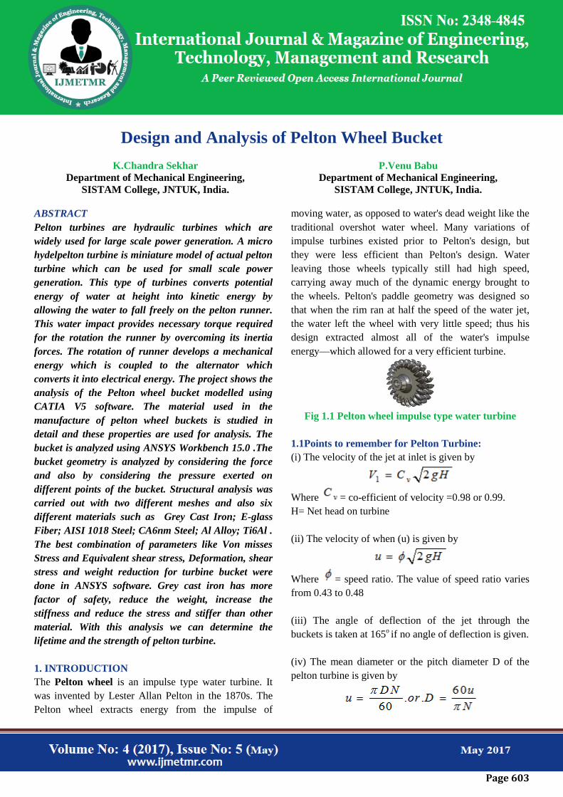
Fig 1.1 Pelton wheel impulse type water turbine
1.1Points to remember for Pelton Turbine:
(i) The velocity of the jet at inlet is given by
Where = co-efficient of velocity =0.98 or 0.99.
H= Net head on turbine
(ii) The velocity of when (u) is given by
Where = speed ratio. The value of speed ratio varies
from 0.43 to 0.48
(iii) The angle of deflection of the jet through the
buckets is taken at 165o if no angle of deflection is given.
(iv) The mean diameter or the pitch diameter D of the
pelton turbine is given by

Page 604
(v) Jet Ratio: it is defined as the ratio of the pitch
diameter (D) of the pelton turbine to the diameter of the
jet (d). It is denoted by m and is given as
m = D/d (=12 for most cases)
(vi) Number of bucket on a runner is given by
Where m = jet ratio
(vii) Number of jets: it is obtained by dividing total rate
of flow through the turbine by the rate of flow of water
through a single jet.
Fig 1.2 Construction of pelton turbine
2. Literature Survey
Nikhil Jacob George et.al. [1]In his paper they
analyzed analysis ofthePelton wheel bucket modelled
using CATIA V5 software.
AlexandrePerrig et.al. [2] In their research paper
theypresent the results of investigations conducted on
the freesurface flow in a Pelton turbine model bucket.
Unsteady numerical simulations, based onthe two-phase
homogeneous model, are performed together with wall
pressure measurementsand flow visualizations.
Maddela Veda RatnaPrakashet.al. [3] In their research
they had employed numerical simulations (CFD
methods) for estimating the flow loss coefficient in
manifolds.
Masahiro Kanazaki [4]In their research paper they
have developed a multi-objective optimization method
for the exhaust manifold by using Divided Range Multi-
objective Genetic Algorithm.
Hong Han-Chi et.al. [5] In their research paper they
used GT-Power, 1-dimensional software, for estimating
the engine performance of a single cylinder IC engine.
The power output predicted from the software was
compared against the experimental data.
TanerGocmez et.al.[6] in their ―Designing Exhaust
Manifolds Using Integral Engineering Solutions‖
focused on the development of a reliable approach to
predict failure of exhaust manifolds and on the removal
of structural weaknesses through the optimization of
design.
Martinez-Martinez et.al. [7] In their paper theyhad
performed CFD analysis to estimate the performance of
the exhaust manifold while placing the catalytic
converter near to it (Close-Coupled Catalytic Converter).
Benny Paul et.al. [8] In this research paper he
conducted CFD simulations on manifold of direct
injection diesel engine.
MohdSajid Ahmed et.al. [9] In his research paper
theyhad applied CFD methods to identify the optimum
exhaust manifold for a 4-stroke 4-cylinder SI engine.
I.P. Kandylas et.al. [10] In this paper theyhad
developed an exhaust system heat transfer model that
included the steady state and transient heat conduction as
well as convection and radiation.
Bin Zou et al. [11] in their research paper they have
discussed the impact of temperature effect on exhaust
manifold modal analysis by mapping temperature field
from the CFD software and then heat conduction process
is analyzed in FEM software with the temperature field
boundary conditions.
P.L.S.Muthaiah et.al. [12] He has analyzed the exhaust
manifold in order to reduce the backpressure and also to
increase the particulate matter filtration.
K.S. Umesh et.al. [13] In their research paper they
worked on eight different models of exhaust manifold
Page 605
were designed and analyzed to improve the fuel
efficiency by lowering the backpressure and also by
changing the position of the outlet of the exhaust
manifold and varying the bend length.
Vivekananda Navadagi et.al. [14] In their research
paper they analyzed the flow of exhaust gas from two
different modified exhaust manifold with the help of
Computational fluid dynamics.
Kulalet.al. [15]In their research work they
comprehensively analyzes eight different models of
exhaust manifold and concluded the best possible design
for least fuel consumption.
Simon Martinez-Martinezet.al. [16] In their paper they
had performed CFD analysis to estimate the
performance of the exhaust manifold while placing the
catalytic converter near to it (Close-Coupled Catalytic
Converter).
Gopaal et.al [17] in his paper he note that the exhaust
pulse, created due to the release of high pressure exhaust
gas from the cylinder to the exhaust manifold, would
have three pressure heads – high, medium and low.
K.H. Park et.al. [18] in their paper―Modeling and
Design of Exhaust Manifold Under Thermo mechanical
Loading ―, had proposed a thermal stress index (TSI) for
designing the exhaust manifold.
J.DavidRathnaraj et.al [19] in his work ―Thermo
mechanical fatigue analysis of stainless steel exhaust
manifolds‖ had proposed a model based on Isothermal
data.
S.N.Ch.Dattu.Vet.al. [20] In his paper heperformed
thermal analysis for the tubular type ICEngine exhaust
manifold for various operating conditions.
3. METHOLDOLOGIES
CATIA (Computer Aided Three-dimensional Interactive
Application)is a multi-platform CAD/CAM/CAE
commercial software suite developed by the French
company Assault Systems. Written in the C++
programming language, CATIA is the cornerstone of the
Assault Systems product lifecycle management software
suite.
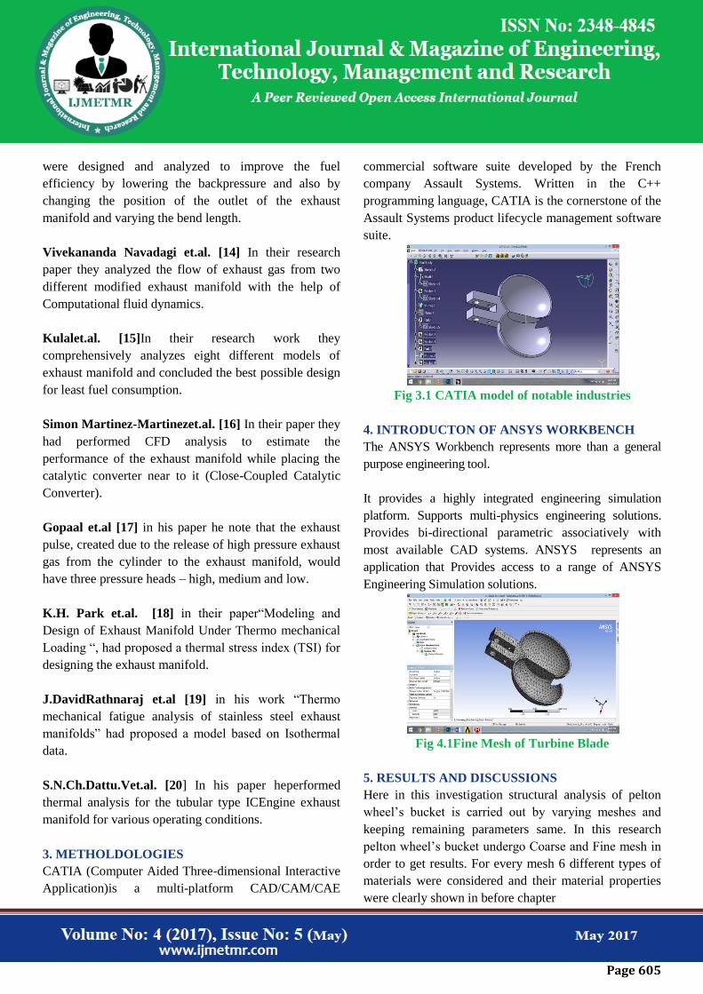
Fig 3.1 CATIA model of notable industries
4. INTRODUCTON OF ANSYS WORKBENCH
The ANSYS Workbench represents more than a general
purpose engineering tool.
It provides a highly integrated engineering simulation
platform. Supports multi-physics engineering solutions.
Provides bi-directional parametric associatively with
most available CAD systems. ANSYS represents an
application that Provides access to a range of ANSYS
Engineering Simulation solutions.
Fig 4.1Fine Mesh of Turbine Blade
5. RESULTS AND DISCUSSIONS
Here in this investigation structural analysis of pelton
wheel’s bucket is carried out by varying meshes and
keeping remaining parameters same. In this research
pelton wheel’s bucket undergo Coarse and Fine mesh in
order to get results. For every mesh 6 different types of
materials were considered and their material properties
were clearly shown in before chapter

Page 606
Even though the materials used for analysis are same
due to variation in meshing the results varied and clearly
shown in the results and in figures. Materials used to
perform analysis were Grey Cast Iron; E-glass Fiber;
AISI 1018 Steel; CA6nm Steel; Al Alloy; Ti6Al
Figure 5.1 Pelton Wheel’s Bucket Showing Fixed
Supports
Case -1: Structural Analysis on Pelton Wheel’s
Bucket with Various Materials using Coarse Mesh
Material: Grey Cast Iron
Figure 5.2 Total deformations in Grey Cast Iron Bucket
The maximum deformation got during the analysis in the
pelton wheel’s bucket is 0.0124mm and a minimum
deformation of about 0.0013mm
Figure 5.3 Equivalent Elastic Strain in bucket
Here in this analysis too coarse mesh is used and got
strain about maximum value of 6.32 e^-5 and minimum
of about 9.337 e^-9.
Figure 5.4 Equivalent Von-Mises stress in bucket
maximum stress of about 5.126 MPa and a minimum of
0.00075 MPa
Figure 5.5 Maximum shear stress
maximum shear stress of about 2.615 MPa and a
minimum of 0.000398 MPa
Material: E-Glass Fiber
Figure 5.6 Total Deformation in E-Glass Bucket
The maximum deformation got during the analysis in the
pelton wheel’s bucket is 0.0139 mm and a minimum
deformation of about 0 mm
Figure 5.7 Equivalent Elastic Strain

Page 607
maximum value of 7.09 e^-5 and minimum of about
9.7811 e^-9.
Figure 5.8 Equivalent von-mises stress
maximum stress of about 5.126 MPa and a minimum of
0.00065 MPa
Figure 5.9 Maximum shear stress
maximum shear stress of about 2.613 MPa and a
minimum of 0.000359 MPa
Material:AISI 1018 Steel
Figure 5.10 Total deformation in AISI 1018 Steel
Bucket
The maximum deformation got during the analysis in the
pelton wheel’s bucket is 0.00496 mm and a minimum
deformation of about 0 mm
Figure 5.11 Equivalent elastic strain
maximum value of 2.528 e^-5 and minimum of about
3.203 e^-9.
Figure 5.12 Equivalent von-mises stress
maximum stress of about 5.133 MPa and a minimum of
0.00065 MPa
Figure 5.13 Maximum shear stress
Material:CA6NM Steel
Figure 5.14 Total deformation of CA^NM Steel bucket
The maximum deformation got during the analysis in the
pelton wheel’s bucket is 0.005099 mm and a minimum
deformation of about 0 mm
Figure 5.15 Equivalent elastic strain
Page 608
maximum value of 2.59 e^-5 and minimum of about
3.72 e^-9.
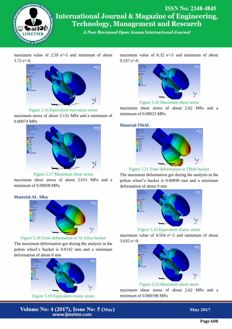
Figure 5.16 Equivalent von-mises stress
maximum stress of about 5.131 MPa and a minimum of
0.00074 MPa
Figure 5.17 Maximum shear stress
maximum shear stress of about 2.615 MPa and a
minimum of 0.00038 MPa
Material:AL Alloy
Figure 5.18 Total deformation in Al Alloy bucket
The maximum deformation got during the analysis in the
pelton wheel’s bucket is 0.0142 mm and a minimum
deformation of about 0 mm
Figure 5.19 Equivalent elastic strain
maximum value of 6.32 e^-5 and minimum of about
9.337 e^-9.
Figure 5.20 Maximum shear stress
maximum shear stress of about 2.62 MPa and a
minimum of 0.00023 MPa
Material:TI6AL
Figure 5.21 Total deformation in TI6Al bucket
The maximum deformation got during the analysis in the
pelton wheel’s bucket is 0.00890 mm and a minimum
deformation of about 0 mm
Figure 5.22 Equivalent elastic strain
maximum value of 4.554 e^-5 and minimum of about
3.035 e^-9.
Figure 5.23 Maximum shear stress
maximum shear stress of about 2.62 MPa and a
minimum of 0.000198 MPa
Page 609
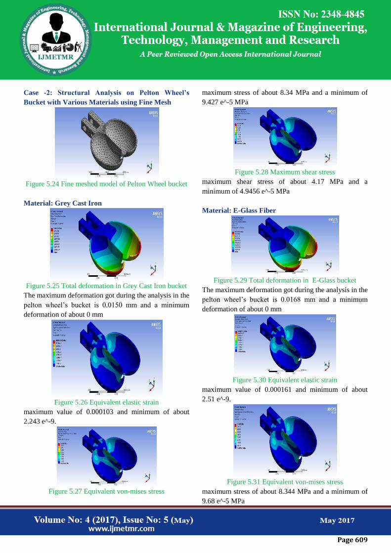
Case -2: Structural Analysis on Pelton Wheel’s
Bucket with Various Materials using Fine Mesh
Figure 5.24 Fine meshed model of Pelton Wheel bucket
Material: Grey Cast Iron
Figure 5.25 Total deformation in Grey Cast Iron bucket
The maximum deformation got during the analysis in the
pelton wheel’s bucket is 0.0150 mm and a minimum
deformation of about 0 mm
Figure 5.26 Equivalent elastic strain
maximum value of 0.000103 and minimum of about
2.243 e^-9.
Figure 5.27 Equivalent von-mises stress
maximum stress of about 8.34 MPa and a minimum of
9.427 e^-5 MPa
Figure 5.28 Maximum shear stress
maximum shear stress of about 4.17 MPa and a
minimum of 4.9456 e^-5 MPa
Material: E-Glass Fiber
Figure 5.29 Total deformation in E-Glass bucket
The maximum deformation got during the analysis in the
pelton wheel’s bucket is 0.0168 mm and a minimum
deformation of about 0 mm
Figure 5.30 Equivalent elastic strain
maximum value of 0.000161 and minimum of about
2.51 e^-9.
Figure 5.31 Equivalent von-mises stress
maximum stress of about 8.344 MPa and a minimum of
9.68 e^-5 MPa
Page 610
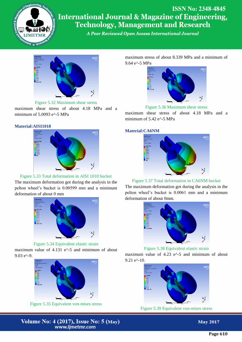
Figure 5.32 Maximum shear stress
maximum shear stress of about 4.18 MPa and a
minimum of 5.0093 e^-5 MPa
Material:AISI1018
Figure 5.33 Total deformation in AISI 1018 bucket
The maximum deformation got during the analysis in the
pelton wheel’s bucket is 0.00599 mm and a minimum
deformation of about 0 mm
Figure 5.34 Equivalent elastic strain
maximum value of 4.131 e^-5 and minimum of about
9.03 e^-9.
Figure 5.35 Equivalent von-mises stress
maximum stress of about 8.339 MPa and a minimum of
9.64 e^-5 MPa
Figure 5.36 Maximum shear stress
maximum shear stress of about 4.18 MPa and a
minimum of 5.42 e^-5 MPa
Material:CA6NM
Figure 5.37 Total deformation in CA6NM bucket
The maximum deformation got during the analysis in the
pelton wheel’s bucket is 0.0061 mm and a minimum
deformation of about 0mm.
Figure 5.38 Equivalent elastic strain
maximum value of 4.23 e^-5 and minimum of about
9.21 e^-10.
Figure 5.39 Equivalent von-mises stress

Page 611
maximum stress of about 8.33 MPa and a minimum of
9.43 e^-5 MPa
Material:TI6AL
Figure 5.40 Total deformation in TI6Al bucket
The maximum deformation got during the analysis in the
pelton wheel’s bucket is 0.0107mm and a minimum
deformation of about 0 mm.
Figure 5.41 Equivalent elastic strain
maximum value of 7.43 e^-5 and minimum of about
1.669 e^-9.
Figure 5.42 Maximum shear stress
maximum shear stress of about 4.2081 MPa and a
minimum of 5.67 e^-5 MPa
Material: Al Alloy
Figure 5.43 Total deformation in Al alloy bucket
The maximum deformation got during the analysis in the
pelton wheel’s bucket is 0.0172 mm and a minimum
deformation of about 0 mm.
Figure 5.44 Equivalent elastic strain
maximum value of 0.00011 and minimum of about 2.65
e^-9.
Figure 5.45 Maximum shear stress
maximum shear stress of about 4.201 MPa and a
minimum of 5.525 e^-5 MPa
Figure 5.46 Equivalent von-mises stress
maximum stress of about 8.34 MPa and a minimum of
9.95 e^-5 MPa
6. CONCLUSION
Pelton turbines are hydraulic turbines which are widely
used for large scale power generation. In this thesis we
performed the investigation on structural analysis of
pelton wheel bucket is carried out by varying meshes
and keeping remaining parameters constant. In this
research pelton wheel’s bucket undergo Coarse and Fine
mesh in order to get results. For every mesh 6 different
types of materials were considered and the outputs total
Page 612
deformation, Equivalent Elastic Strain in bucket,
Equivalent Von-Misses stress and Maximum shear stress
are calculated.
Even though the materials used for analysis are same
due to variation in meshing the results varied. Materials
used to perform analysis were Grey Cast Iron; E-glass
Fiber; AISI 1018 Steel; CA6nm Steel; Al Alloy; Ti6Al.
Among the above materials E-glass Fiber have the best
performance with fine mesh than other materials.
7. References
[1] Nikhil Jacob George, SebinSabu, Kevin Raju Joseph,
―Static Analysis On Pelton Wheel Bucket‖,International
Journal of Engineering Research & Technology
(IJERT)IJERTIJERT,ISSN: 2278-0181, Vol. 3 Issue 3,
March – 2014.
[2] AlexandrePerrig, François Avellan,Jean-Louis
Kueny,MohamedFarhat, ―Flow in a Pelton Turbine
Bucket Numerical and Experimental Investigations‖,
350 / Vol. 128, MARCH 2006 , Transactions of the
ASME.
[3]MohdSajid Ahmed, Kailash B A, Gowreesh,
―DESIGN AND ANALYSIS OF A MULTI-
CYLINDER FOUR STROKE SI ENGINE EXHAUST
MANIFOLD USING CFD TECHNIQUE‖, International
Research Journal of Engineering and Technology
(IRJET) e-ISSN: 2395-0056.
[4]Kanupriya Bajpai, Akash Chandrakar, Akshay
Agrawal, Shiena Shekhar, ―CFD Analysis of Exhaust
Manifold of SI Engine and Comparison of Back Pressure
using Alternative Fuels‖, IOSR Journal of Mechanical
and Civil Engineering (IOSR-JMCE),Volume 14,
Issue1Ver. I (Jan.-Feb. 2017).
[5]K. Nanthagopal, B. Ashok,R. ThundilKaruppa Raj,
―Design considerations and overview of an engine
exhaust manifold gasket‖, Journal of Chemical and
Pharmaceutical SciencesISSN: 0974-2115.
[6]VivekanandNavadagi, SiddaveerSangamad, ―CFD
Analysis of Exhaust Manifold of Multi- Cylinder Petrol
Engine for Optimal Geometry to Reduce Back
Pressure‖, International Journal of Engineering Research
& Technology Vol. 3 - Issue 3 (March - 2014).
[7] K.S.Umesh ,V.K. Pravin and K. Rajagopal ,
―Experimental Investigation of Various Exhaust
Manifold Designs and Comparison of Engine
Performance Parameters for These to Determine Optimal
Exhaust Manifold Design for Various Applications‖,
Proc. of Int. Conf. on Advances in Mechanical
Engineering, AETAME
[8] Gopaal, M MM Kumara Varma, Dr. L Suresh
Kumar, ―THERMAL AND STRUCTURAL
ANALYSIS OF AN EXHAUST MANIFOLD OF A
MULTI CYLINDER ENGINE‖, INTERNATIONAL
JOURNAL OF MECHANICAL ENGINEERING
ANDTECHNOLOGY (IJMET)ISSN 0976 – 6340.
[9] K. S. UMESH, V. K. PRAVIN& K. RAJAGOPAL,
―CFD ANALYSIS OF EXHAUST MANIFOLD OF
MULTI-CYLINDER SI ENGINE TODETERMINE
OPTIMAL GEOMETRY FOR REDUCING EMISSIONS‖,
International Journal of Automobile Engineering ISSN
2277-4785Vol. 3, Issue 4, Oct 2013, 45-56.
[10] Jae Ung Cho, ―A Study on Flow Analysis of
theExhaust Manifold for Automobile‖, International
Journal ofApplied Engineering Research ISSN 0973-
4562 Volume 11, Number 2(2016).
[11] MarupillaAkhilTeja, KatariAyyappa, Sunny Katam
and PangaAnusha, “Analysis of Exhaust Manifold using
Computational Fluid Dynamics”, July 28, 2016.
[12] Rajesh Bisane, Dhananjaykatpatal,
―EXPERIMENTAL INVESTIGATION & CFD
ANALYSIS OF AN SINGLE CYLINDER FOUR
STROKE C.I. ENGINE EXHAUST SYSTEM‖,IJRET,
eISSN: 2319-1163.
Page 613
[13] Dr. K Ashok Reddy, ―Exhaust Manifold
Developmental Activates in Compression Ignition
Engine‖, IJETCAS ISSN-2279-0047.
[14]Gopaal, MMM kumara varma, Dr L sureshkumar
,―Exhaust manifold design-FEA approach‖, IJETT–
Volume17 Number 10–Nov2014 ISSN:2231-5381.
[15] Atul A. Patil,L.G. Navale,V.S. Patil, ―Simulative
Analysis of Single Cylinder Four Stroke C.I. Engine
Exhaust System‖, INTERNATIONAL JOURNAL OF
SCIENCE, SPIRITUALITY, BUSINESS AND
TECHNOLOGY(IJSSBT),Vol. 2,
No.1,November2013ISSN 2277—7261.
Related Documents