International Journal on Research Innovations in Engineering Science and Technology(IJRIEST) Website:www.ijriest.com Email:[email protected] Volume2, Issue 5 ,May-2017 410 Design and Analysis of Kinetic Energy Recovery System in Bicycles Kaustav Nandy 1 , Karan Karthikeyan 2 , Nibin Winston 3 , Freddy Sandle 4 , Basil.M.Varghese 5 1,2,3,4,5 Department of Mechanical Engineering, Matha College of Technology, Manakkappady , N.Paravur, Ernakulam, Kerala , India [email protected] Abstract—Kinetic Energy Recovery System, commonly abbreviated KERS, is a system to recover the Kinetic energy of a moving vehicle under braking. This system stores the kinetic energy in the form of potential energy and converts it back to kinetic energy when needed. When riding a bicycle it becomes too tiresome to start the bicycle again after braking. If the bicycle is provided with a kinetic energy recovery system then the rider will have two power sources that he can use at his will. When brakes are applied kinetic energy is wasted because the kinetic energy converts into heat energy due to friction at the contact surface and the heat energy dissipates into the atmosphere due to thermal radiation. Vehicles equipped with KERS devices are able to take some of its kinetic energy out slowing down the vehicle. This is a form of braking in which energy is not wasted, instead gets stored in some device. Using a proper mechanism, this energy that is stored in terms of potential energy can be converted back into kinetic energy to give the vehicle an extra boost of power. In the literature review different types of available KERS systems are compared and a mechanical based KERS system is found to be the best suitable for a bicycle. Mechanical KERS system there are of two types, one is a clutch based and another is a CVT based K.E. recovery system. In this project a hybrid of the above two type of KERS systems is designed. Instead of CVT a variable sprocket ratio is used to make the power transmission smoother. Finally the complete manufacturing process of this KERS system is explained elaborately so that any researcher can follow those steps and design a KERS system for his/her bicycle. Keywords— KERS, Regenerative braking, Flywheel energy storage, Flywheel bicycle, Mechanical KERS, Smart braking I. INTRODUCTION A kinetic energy recovery system abbreviated as KERS is an automotive system which recovers the kinetic energy of a moving vehicle under braking. The energy recovered is stored in terms of potential energy a reservoir for later use for acceleration. Examples of reservoir are high voltage batteries, flywheels, hydraulic coupling, etc. The selection of reservoir largely depends on the purpose. In recent days recovering Kinetic energy has become an interesting area of research for many. Let us first find out why? The total energy in this universe can be broadly divided into two parts Potential Energy and Kinetic Energy. The Potential Energy is the energy possessed by the body due to its position or state where as the Kinetic Energy is the energy the body gains due to its motion. As we know notion is a relative concept so as the Kinetic energy. For example a car possess some Kinetic energy with respect to road but with respect another car moving at same speed it has no Kinetic energy. So when we need to impart motion into a body we have to convert some amount potential energy into Kinetic energy. When that body has to come to rest, that amount of kinetic energy needs to get converted into Potential energy. But in nature the form of potential energy to which the Kinetic energy gets converted is of a lower grade, in most of the cases, and is very difficult to reuse. Taking the example of a car, when we run a car we burn petrol and convert the potential energy of the petrol into the Kinetic energy of the car and when we apply the brakes the kinetic energy converts into heat energy in the brake callipers and eventually gets diffused into the atmosphere. If this energy would have been saved it could have been used. There are two type of Kinetic Energy Recovery Systems which have gained popularity in recent days. One is Electrical KERS and another is Mechanical KERS. Both have their respective pros and cons. The electrical system is less efficient but it can store power for a longer duration and gives us the agility to manipulate the torque and rpm output as per our requirement. In the other hand the mechanical system has a better efficiency (nearly twice as that of the prior one) but it is prone to decay due to its inherent property of friction, though it is very small in value, hence cannot be stored for loner period and need to be used within a short period of time. In the real world we can find many situations where we need to use the recovered Kinetic energy with in very short span of time of its recovery and we don’t eve n need a wide range of torque and rpm output as a particular range of torque & rpm combinations satisfy our requirements completely. A bicycle is a perfect example of this kind. 2 This is why KERS for bicycle has been chosen as the final year project. There has been a lot of work related to this topic but this topic still needs more research. During the project the goal will be to design an optimized mechanical KERS which will improve the storing time of the kinetic energy as well as improve the compatibility and manufacturability of the system.

Welcome message from author
This document is posted to help you gain knowledge. Please leave a comment to let me know what you think about it! Share it to your friends and learn new things together.
Transcript

International Journal on Research Innovations in Engineering Science and Technology(IJRIEST)
Website:www.ijriest.com Email:[email protected]
Volume2, Issue 5 ,May-2017
410
Design and Analysis of Kinetic Energy Recovery
System in Bicycles
Kaustav Nandy1, Karan Karthikeyan
2, Nibin Winston
3, Freddy Sandle
4, Basil.M.Varghese
5
1,2,3,4,5Department of Mechanical Engineering, Matha College of Technology, Manakkappady , N.Paravur, Ernakulam, Kerala ,
India
Abstract—Kinetic Energy Recovery System, commonly abbreviated KERS, is a system to recover the Kinetic energy of a moving
vehicle under braking. This system stores the kinetic energy in the form of potential energy and converts it back to kinetic energy
when needed. When riding a bicycle it becomes too tiresome to start the bicycle again after braking. If the bicycle is provided with a
kinetic energy recovery system then the rider will have two power sources that he can use at his will. When brakes are applied kinetic
energy is wasted because the kinetic energy converts into heat energy due to friction at the contact surface and the heat energy
dissipates into the atmosphere due to thermal radiation. Vehicles equipped with KERS devices are able to take some of its kinetic
energy out slowing down the vehicle. This is a form of braking in which energy is not wasted, instead gets stored in some device. Using
a proper mechanism, this energy that is stored in terms of potential energy can be converted back into kinetic energy to give the
vehicle an extra boost of power. In the literature review different types of available KERS systems are compared and a mechanical
based KERS system is found to be the best suitable for a bicycle. Mechanical KERS system there are of two types, one is a clutch
based and another is a CVT based K.E. recovery system. In this project a hybrid of the above two type of KERS systems is designed.
Instead of CVT a variable sprocket ratio is used to make the power transmission smoother. Finally the complete manufacturing
process of this KERS system is explained elaborately so that any researcher can follow those steps and design a KERS system for
his/her bicycle.
Keywords— KERS, Regenerative braking, Flywheel energy storage, Flywheel bicycle, Mechanical KERS, Smart braking
I. INTRODUCTION
A kinetic energy recovery system abbreviated as KERS is an automotive system which recovers the kinetic energy of a moving vehicle under braking. The energy recovered is stored in terms of potential energy a reservoir for later use for acceleration. Examples of reservoir are high voltage batteries, flywheels, hydraulic coupling, etc. The selection of reservoir largely depends on the purpose. In recent days recovering Kinetic energy has become an interesting area of research for many. Let us first find out why? The total energy in this universe can be broadly divided into two parts Potential Energy and Kinetic Energy. The Potential Energy is the energy possessed by the body due to its position or state where as the Kinetic Energy is the energy the body gains due to its motion. As we know notion is a relative concept so as the Kinetic energy. For example a car possess some Kinetic energy with respect to road but with respect another car moving at same speed it has no Kinetic energy. So when we need to impart motion into a body we have to convert some amount potential energy into Kinetic energy. When that body has to come to rest, that amount of kinetic energy needs to get converted into Potential energy. But in nature the form of potential energy to which the Kinetic energy gets converted is of a lower grade, in most of the cases, and is very difficult to reuse. Taking the example of a car, when we run a car we burn petrol and convert the potential energy of the petrol into the Kinetic energy of the car and when we apply the brakes the kinetic energy converts into heat energy in the brake callipers and eventually gets diffused into the atmosphere. If this energy would have been saved it could have been used. There are two type of Kinetic Energy Recovery Systems which have gained popularity in recent days. One is Electrical KERS and another is Mechanical KERS. Both have their respective pros and cons. The electrical system is less efficient but it can store power for a longer duration and gives us the agility to manipulate the torque and rpm output as per our requirement. In the other hand the mechanical system has a better efficiency (nearly twice as that of the prior one) but it is prone to decay due to its inherent property of friction, though it is very small in value, hence cannot be stored for loner period and need to be used within a short period of time. In the real world we can find many situations where we need to use the recovered Kinetic energy with in very short span of time of its recovery and we don’t even need a wide range of torque and rpm output as a particular range of torque & rpm combinations satisfy our requirements completely. A bicycle is a perfect example of this kind. 2 This is why KERS for bicycle has been chosen as the final year project. There has been a lot of work related to this topic but this topic still needs more research. During the project the goal will be to design an optimized mechanical KERS which will improve the storing time of the kinetic energy as well as improve the compatibility and manufacturability of the system.

International Journal on Research Innovations in Engineering Science and Technology(IJRIEST)
Website:www.ijriest.com Email:[email protected]
Volume2, Issue 5 ,May-2017
411
II. LITERATURE SURVEY
A. History of KERS:
The first of these systems to be revealed was the Flybrid. This system weighs 24 kg (53 lbs) and has an energy capacity of 400 kJ after allowing for internal losses. A maximum power boost of 60 kW (81.6 PS, 80.4 HP) for 6.67 seconds is available. The 240 mm (9.4") diameter flywheel weighs 5.0 kg (11 lbs.) and revolves at up to 64,500 rpm. The maximum torque generated at the flywheel is 18 Nm (13.3 ft-lbs), and the torque at the gearbox connection is correspondingly higher for the change in speed. The system occupies 13 liters of volume. Two small accidents were reported during testing of various KERS systems in the year 2008. The first incident happened with Red Bull Racing when the team tested their KERS battery for the first time in July, the battery malfunctioned and accidentally caused a fire, to avoid any causality evacuated the building. The second incident happened within a week. A BMW Sauber mechanic got an electric shock when he touched Christian Klien's KERS-equipped car during a test at the Jerez circuit. Formula one has stated that they support environment friendly technology and thy have allowed use of KERS in 2009 F1 championship. Due to the previous accidents with KERS system many teams did not use it in their cars. Only four teams opted for KERS in 2009 session that to in few races only. Ferrari, BMW, Renault and McLaren were the fore teams using the KERS in their cars. Due to some malfunctioning BMW and Renault stopped using this system during the season. Vodafone McLaren Mercedes was the first team to win a F1 GP using a KERS equipped car on July 26, 2009 at the Hungarian Grand Prix. Lewis Hamilton was driving that car to become the first driver to win a pole position with a car equipped with KERS. In that race only their car which was also equipped with KERS finished fifth. Kimi Räikkönen won Belgian Grand Prix with KERS equipped Ferrari on 30th August 2009. This time the KERS contributed directly to race victory. Giancarlo Fisichella who came out second in that race claimed that he was faster than Kimi Räikkönen and Kimi only beat him because of KERS equipped car. KERS helped Kimi win the race substantially and get the lead. In 2011, though KERS was legal no team used it on a united assertion. In 2011 F1 changed the rules and increased the minimum driver and car weight limit by 20Kg and the total weight to 4 640kg. This time the FOTA teams agreed to use the KERS devices and KERS is back in race. This time also the KERS system was options but all the teams except three used KERS devices on their cars.
WilliamsF1 was the first to develop their own flywheel-based KERS system. Unfortunately they could not use it in their F1 cars because of packaging issues. Thus they developed an electrical KERS system of their own. They even set up Williams Hybrid Power to sell their developments in the field of KERS. In the year 2012 Audi announced to use Williams Hybrid Power in its Le Mans R18 hybrid car. By the year 2014, the power accumulation capacity of KERS systems has increased from 80bhp to 160bhp. F1 started using 1.6 litre V6 engines with an integration with KERS devices instead of 2.4 litre V8 engines. In the field of motor racing Bosch Motorsport Service is a pioneer and it is developing a KERS that can be used in motorbikes. In the year 2009 KTM racing boss Harald Bartol announced that during the 2008 season-ending the factory raced with a KERS secretly fitted to Tommy Koyama's motorcycle in 125cc Valencian Grand Prix. This use of KERS was illegal, hence the team was banned from using that equipment in future. KERS system can also be used on a bicycle. Students of the University of Michigan working with EPA has developed a system called RBLA (hydraulic Regenerative Brake Launch Assist). Recovery of Kinetic energy has also been done by mounting a flywheel on a bike frame and 5 connecting it with a CVT to the back wheel. By shifting the gear, 20% of the kinetic energy can be stored in the flywheel, ready to give an acceleration boost by re-shifting the gear.
B. Inference from literature survey:
Concluding this literature review we can say that Mechanical KERS is the most suitable type of Kinetic energy recovery system that we can use for a bicycle. The constraints for the design and development of the KERS for the bicycle are recognized. As there has not been much work related to bicycle KERS this field needs extensive research and development. No one has done any work on the mass production procedure of this product and its marketing. This field needs serious attention. A tie between the clutch type mechanical KERS and CVT type mechanical KERS can be broken by further study. Flywheel technology is rising across many kinds of technology. It is a pollution free method of storing energy having many current applications as well as future uses. In the case of road vehicles it necessary to be concerned about energy efficiency, especially when considering pollution per unit of energy output. Any system that can regenerate energy from braking can help that, but flywheels have the potential to increase the efficiency of road vehicles without any direct or indirect negative effects on the environment. The use of batteries can cause serious environmental effects at the time of its manufacturing and disposal whereas flywheels have a very small environmental effect only at its time of their production. Flywheels have the potential to heavily outweigh those costs through their uses. Bicycles don’t have the pollution problems like cars and other modes of transportation, but use of a flywheel as KERS in a bicycle can tremendously increase its efficiency.
III. WORKING PRINCIPLE:
The working principle of the KERS system is described below in details.
1. To actuate the KERS the lever near the left brake is to be actuated. This pulls the wire connected to the clutch drive and rotates it by some angle less than 180°.

International Journal on Research Innovations in Engineering Science and Technology(IJRIEST)
Website:www.ijriest.com Email:[email protected]
Volume2, Issue 5 ,May-2017
412
2. Due to the rotational motion of the clutch drive it undergoes translational motion, because its counterpart is fixed.
3. The translational motion of the clutch drive pushes the clutch plate to bring it in contact with the flywheel.
4. In this design we have connected the KERS actuator on the opposite side of the left brake lever so when clutch is actuate brake is not actuated (which is the default position) and when the brake will be actuated the clutch will automatically disengage.
5. The clutch drive is always in the actuated state with the help of a sprig that always keeps it rotated by nearly 150°.The rest 30° is for wear and tear compensation.
6. The clutch plate is a continuously moving part as it is connected with the front sprocket using three keys.
7. The front sprocket is driven by the rear sprockets through a chain drive.
8. The rear sprockets are a set of sprockets on which the chain can change position to get different gear ratios. These are interconnected and rotate at same RPM as the rear wheel.
9. During charging of the flywheel, power flows as follows Rear Wheel → Rear Sprocket → Chain Drive → Front Sprocket → Clutch → Flywheel
10. During the discharging cycle, power flows exactly in the reverse direction. Flywheel → Clutch → Front Sprocket → 11. As there are 5 sprockets on the rear sprocket system we can have 5 different gear ratios and can manipulate them to get the required charging and discharging conditions.
12. During charging it is preferred to use a higher gear ratio (Rear: Front) so that the flywheel can get charged within less time. But this will cause higher initial jerk while engaging.
13. So it is preferred to engage the clutch at the lowest gear ratio and then increase the gear ratio to the maximum.
14. This has an additional advantage. With every increasing gear ratio the relative velocity of the flywheel as compared to the rear wheel decreases. Thus additional torque acts on the flywheel and accelerates it to even higher speed. This way the flywheel can attain its maximum desired RPM smoothly.
15. Now the flywheel has its maximum potential energy. So if the driver wants to brake, he simply applies the brake and the flywheel automatically disengages as the string that actuate the flywheel is connected to the opposite end of the left handle brake as mentioned earlier.
16. Now coming to the discharging of the flywheel. Discharging can be done for a long time if we keep the sprocket ratio (rear: front) low. But if the gear ratio is more the torque will be more.
17. We need higher torque when discharging starts and low but continuous discharge when the cycle attains some speed.
18. From the previous discussion we can see that at the end of the charging cycle the gear ratio is at maximum. So when the discharging starts we simply need to reduce the gear ratio in successive intervals.
19. This has another advantage. When the gear ratio is lowered the relative velocity of the flywheel becomes more as compared to the rear wheel. So the power flows from the flywheel to the rear wheel and the cycle accelerates.
20. The gear changer for the KERS system will also be on the left hand side. So the driver has to concentrate only on hand to operate this system. And when he needs to brake (sudden brake) he simply can apply brakes. The cycle will stop.
21. The starting effort will be a little more but not that more because while starting the gear ratio is at minimum. Or if the driver is a bit smart he can apply the brake lever slightly and accelerate the bicycle easily. At that condition the KERS will be disengaged and the brakes are not also applied.
22. In normal riding the sprocket ration stays at minimum. When the rider wants to slow down (mild braking) he can simply increase the sprocket ratio with the help of gear shifter available at his left hand. And when he wants to boost his speed he can simply gear down or reduce the sprocket ratio to accelerate the bicycle.
23.The most important thing the amount of power released from the KERS system is completely controllable. The rider can release the exact amount of power he needs to release and get the required acceleration

International Journal on Research Innovations in Engineering Science and Technology(IJRIEST)
Website:www.ijriest.com Email:[email protected]
Volume2, Issue 5 ,May-2017
413
Fig.1 Flywheel KERS Bicycle
IV. FINITE ELEMENT ANALYSIS:
Finite element analysis of every component has become necessary for any design process. Every designed thing should be
checked whether it can take the desired load and sustain the working environment. Product life cycle is an important term
coined in this field. FEA helps us to identify the mistakes in our designs. It shows the tress concentration and strain at different
desired points. Even it helps to directly find out the factor of safety for a component. The best part is we can change the part
material and test as many times as we want without losing any raw material. In this project also extensive FEA analysis has
been done on different components to check their integrity and sustainability. All the results of those works have been
mentioned below:
A. Flywheel:
Flywheel is the most rigid component among the components of a KERS system which has the least amount of chance to
undergo a failure. Forces acting on the flywheel:
Gravitational force
Rotational inertia force (66.66rps)
Force due to actuation of clutch (373.4N)
Supports of the flywheel:
Bearing support.
Displacement support
Equivalent Elastic Strain
Equivalent Stress

International Journal on Research Innovations in Engineering Science and Technology(IJRIEST)
Website:www.ijriest.com Email:[email protected]
Volume2, Issue 5 ,May-2017
414
Factor of Safety
Total Deformation
From the FEA analysis photos we can see: Factor of safety of the flywheel = 15.
Maximum equivalent stress = 108.5KPa
Maximum equivalent strain = 1.5e-6
Maximum deflection = 6.1e-8m
The above data show that the design of the flywheel is completely safe.
B. Clutch:
Clutch is the most vulnerable component of the KERs system. It is exposed to continuous engagement and disengagement with
the flywheel.
Force acting on clutch:
Force due to actuation of the clutch F = 373.4N
Gravitational force
Rotational inertia force Speed of rotation when the cycle runs at 30Kmph amd the sprocket ratio is maximum (s=3)
=𝜔2 = 30× 5 18 × 2𝜋 𝜋𝐷 ×𝑠 = 66.66rad/sec
Torque T = 8.96Nm
Supports:
Compression only support
Contact support, no displacement

International Journal on Research Innovations in Engineering Science and Technology(IJRIEST)
Website:www.ijriest.com Email:[email protected]
Volume2, Issue 5 ,May-2017
415
From the FEA analysis photos it can be seen:
Max. equivalent stress = 75.03MPa Max. equivalent strain = 0.00108
Min. FOS = 3.732
Overall FOS = 12
Maximum deflection = 0.09mm
We can see on all the clutch the factor of safety is 10 to 15. Only on 4 peripheral points of the clutch the FOS falls below 10.
For that if we are changing the material the component will be over engineered and we will increase the weight unnecessarily.
To avoid failures at those point we can do heat treatment to increase the strength in the peripheral area. We can also use
electromagnetic plating of stronger materials on those areas.
C. Front Sprocket:
This part is made up of stainless steel so there is a very less chance of damage for this part sill the FEA analysis should be done.
Forces acting:

International Journal on Research Innovations in Engineering Science and Technology(IJRIEST)
Website:www.ijriest.com Email:[email protected]
Volume2, Issue 5 ,May-2017
416
Gravitational force
Rotational inertia force
Torque T = 8.96Nm
Supports:
Compression only support
Keyway support

International Journal on Research Innovations in Engineering Science and Technology(IJRIEST)
Website:www.ijriest.com Email:[email protected]
Volume2, Issue 5 ,May-2017
417
From the above pictures we can see:
Maximum stress = 17.26MPa
Maximum strain = 1.2e-4
Minimum FOS = 11.993
Maximum deflection = 1.81e-6m
The above data show that the design if the front sprocket is completely safe and there is no chance of any kind of failure.
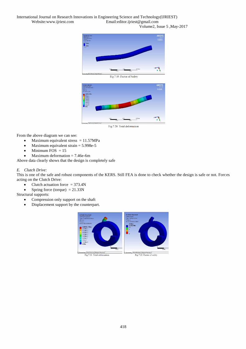
D. Central Shaft:
This is one of the safe and robust components of the KERS. Still FEA is done to check whether the design is safe or not. Forces
acting on the Clutch Drive:
Clutch actuation force = 373.4N
Spring force (torque) = 21.33N
Structural supports:
Compression only support on the shaft
Displacement support by the counterpart.
International Journal on Research Innovations in Engineering Science and Technology(IJRIEST)
Website:www.ijriest.com Email:[email protected]
Volume2, Issue 5 ,May-2017
418
From the above diagram we can see:
Maximum equivalent stress = 11.57MPa
Maximum equivalent strain = 5.998e-5
Minimum FOS = 15
Maximum deformation = 7.46e-6m
Above data clearly shows that the design is completely safe
E. Clutch Drive:
This is one of the safe and robust components of the KERS. Still FEA is done to check whether the design is safe or not. Forces
acting on the Clutch Drive:
Clutch actuation force = 373.4N
Spring force (torque) = 21.33N
Structural supports:
Compression only support on the shaft
Displacement support by the counterpart.

International Journal on Research Innovations in Engineering Science and Technology(IJRIEST)
Website:www.ijriest.com Email:[email protected]
Volume2, Issue 5 ,May-2017
419
From the above diagram we can see:
Maximum equivalent stress = 68.85MPa
Maximum equivalent strain = 9.9e-5
Minimum FOS = 13.762
Maximum deformation = 1.5e-7m
Above data clearly shows that the design is completely safe.
V. MANUFACTURING PROCESS
The manufacturing process of each and every model designed in this project has been mentioned below. Manufacturing process
of a single component involves the below mentioned steps.
1. Raw material required.
2. Primary machining
3. Testing and inspection
4. Insulation coating to prevent corrosion
A. Flywheel:
The manufacturing process of the flywheel is easiest of all.
Raw material:
a) Aluminium disk Outer Dia. : 26cm Thickness : 5.5cm
Primary Machining:
a) Do Facing operation on both sides of the flywheel to bring the surface finish and reduce the thickness to 5cm.
Face milling.
b) Do Drilling with a 12mm drill bit (HSS) at the center of the flywheel.
c) Then do turning to reduce its outer diameter to 25cm
d) During turning hold the flywheel with the help of tailstock to avoid any eccentricity. Using mandrel.
e) Do Boring operation to increase the diameter of the hole to 28mm with a tolerance of -0.05mm up to a depth
of 8mm.
f) Do the same operation on the other side.
Testing and inspection:
a) Go gauge of 12mm
b) No-Go gauge of 28mm
c) Go gauge of 27.95mm.
d) Check the eccentricity using the coordinate measurement machine (CMM).
Insulation coating to prevent corrosion
a) As aluminium is corrosion free no protective coating is required.
b) No antifriction coating is also require because we want COF to be high between flywheel and the clutch
B. Clutch:
The manufacturing process of the clutch is mentioned below.
Raw Material:
a) Aluminium Required amount Molten Aluminium
Primary machining:

International Journal on Research Innovations in Engineering Science and Technology(IJRIEST)
Website:www.ijriest.com Email:[email protected]
Volume2, Issue 5 ,May-2017
420
a) Do the centrifugal casting to get the initial shape
b) Drilling the central hole with 12mm drill bit with 0.05mm tolerance.
c) Machining: use cylindrical grinding to get the finishing on the peripheral surfaces.
d) Do face milling to get the flat finished surfaces.
e) Do the ball nose end milling to get the straight grooves of 3mm diameter.
f) Do the grooving operation with the U-shape grooving tool to the circular groove of thickness 1.75mm and depth
1mm.
Testing and inspection.
a) Go gauge of 12mm.
b) No go gauge of 20mm.
Insulation coating to prevent corrosion.
a) Put DLC (diamond like carbon) coating on the end surface of the cylinder and also in the 12mm groove. It
increases the surface hardness to resist wear and at the same time reduces friction significantly.
C. Front Sprocket:
The manufacturing process of the front sprocket is mentioned below.
Raw Material:
a) Stainless Steel cylinder SS304 stainless steel Outer Diameter = internal diameter of the sprocket
b) Stainless Steel Sprocket 15 teeth
Primary machining:
a) Central drilling with a 20mm drill bit.
b) Drilling with 3mm diameter drill bit at 3 equidistant points on the inner periphery of the hollow cylinder
c) TIG welding of the cylinder and the sprocket
Testing and inspection.
a) Go gauge of 20mm.
b) No go gauge of 20.1mm.
c) Go gauge of 3mm d. No go gauge of 3.05mm.
Insulation coating to prevent corrosion.
a) Put DLC (diamond like carbon) coating on all the surfaces of the front sprocket. It increases the surface
hardness to resist wear and at the same time reduces friction significantly.
D. Clutch Drive:
The manufacturing process of the clutch drive is mentioned below. Its counterpart can be generated in exactly the same
way.
Raw Material:
a) Stainless Steel cylinder SS304 stainless steel Outer Diameter = 2cm
Primary machining:
a) Central drilling with a 12mm drill bit with 0.05mm tolerance
b) CNC end milling to get the contour.
c) Helical interpolator can be used to generate the helical surface, for this G code has to be written
d) If CAM is available with CNC the no need to worry, by simply putting the CAD model in the machine the
product will be automatically machined.
Testing and inspection.
a) Go gauge of 12mm.
b) No go gauge of 12.05mm.
Insulation coating to prevent corrosion.
a) Put DLC (diamond like carbon) coating on all the surfaces of the clutch drive. It increases the surface hardness
to resist wear and at the same time reduces friction significantly.
E. Central Shaft:
The manufacturing process of the central shaft is mentioned below.
Raw Material:
a) Stainless Steel cylinder SS304 stainless steel Outer Diameter = 13mm Length = 30cm
Primary machining:

International Journal on Research Innovations in Engineering Science and Technology(IJRIEST)
Website:www.ijriest.com Email:[email protected]
Volume2, Issue 5 ,May-2017
421
a) Turning operation of the shaft to decrease its diameter to 12mm with a tolerance of -0.05mm.
b) Grooving operation to make grooves of thickness 1mm and depth 1mm.
c) The distance between the grooves should be 5cm.
Testing and inspection.
a) Go gauge of 11.95mm.
b) No go gauge of 12mm.
Insulation coating to prevent corrosion.
a) Put DLC (diamond like carbon) coating on all the surfaces of the Central Shaft. Place markings 1 and 2 near
the grooves to represent groove-1 and groove-2.
b) Groove-1 is the groove on the open side of the flywheel.
c) Groove-2 is the groove on the clutch side of the flywheel.
VI. ASSEMBLY PROCESS:
The design of this KERS system has been done keeping in mind the ease the assembly process. The design is focused on user
friendliness. The assembly process of the KERS system is mentioned below:
1. Take the central shaft and place the C-clamp (IS 3075 NE-11) on the groove-1.
2. Press fit the Ball-bearings (IS 6455 SR-00-12-S) on both sides of the Flywheel.
3. Place the Flywheel bearing assembly after the C-clamp. 4
4. Place another C-clamp (IS 3075 NE-11) on groove-2.
5. Take the Clutch and place on the ground face down.
6. Place three Keys (Dia. 3mm and length 8mm) in their respective keyways and insert the Front-sprocket
aligning its keyways with the Keys.
7. Place a C-clamp (IS 3075 HE-20) on the clutch groove to prevent the Front-sprocket from coming out.
8. Place the Clutch Front-sprocket assembly on the central shaft keeping the clutch plate towards the flywheel.
9. Place the Clutch-drive and its counterpart on the Central-shaft after the clutch assembly.
10. Mount the KERS assembly on the support structure by bolting with the corresponding bolts as the threads
made on the shaft.
11. Fix the Clutch-driver counterpart with the mounting either by welding or any other suitable means.
12. Attach the spring and the actuator wire to the Clutch-drive.
13. Attach the multiple gear rear sprocket on the rear wheel.
14. Attach the gear shifter arm as required.
15. Connect the front, the rear sprocket and the gear shifter arm using the chain of required length.
In the figure below the exploded view of the assembly of KERS is shown

International Journal on Research Innovations in Engineering Science and Technology(IJRIEST)
Website:www.ijriest.com Email:[email protected]
Volume2, Issue 5 ,May-2017
422
VII. RESULTS AND DISCUSSION:
The flywheel bicycle increases efficiency on rides where the rider slows often. The additional weight is outweighed by the ability
to recover energy normally lost during braking. Thus the addition of extra weight does not make it difficult for the rider. Also
clutch provided helps in deciding the time period of activity. The overall result is that KERS system is efficient in storing the
energy normally lost in braking and returns it for boosting.
Weight And Performance
Normally energy stored in the flywheel is directly proportional to the weight and radius. Hence increase in weight proves to
improve the performance. But as we know that the maximum safe weight that can be used is limited due to frame properties
and rider compatibility. And also after some extent the radius can‟t be increased and the energy storage thus seems to be
limited to some particular extend. This is also because of the fact that the total running speed is being reduced due to weight.
Energy storage capacity increases with increase in weight but limitation seems to be the speed driving the flywheel. And
performance of system is directly linked with the energy stored. Thus a graph can be plotted between performance and weight.
Optimum value lies between 5 and 8 kg. Energy stored in flywheel, Ek= 1 2 𝐼ω2 Where, „I‟ is the moment of inertia „ω‟ is
the rotational velocity (rpm) Moment of inertia, I = 𝑘𝑚𝑟2 Where, „k‟ is inertial constant (depends on shape) „m‟ is mass of
the disc „r‟ is the radius Thus Ek is directly proportional to the mass of the disc
The flywheel and transmission add weight to the bicycle. The increased weight will add to the energy required to accelerate the
bicycle and to ride it uphill. However, once the rider has provided the energy to reach a cruising speed, the flywheel reduces
the energy cost of slowing down from this speed since it aids in subsequent acceleration. Roads are optimal environment for
the flywheel bicycle because it‟s flat and there are lots of reasons for the cyclist to slow down. The performance versus weight
graph is shown in figure 6 and the comparison of weight of ordinary and flywheel bicycle is shown in figure 7 below..
Comparison Analysis
Comparison is made between conventional bicycle and the KERS bicycle. The major things looked up was velocity, kinetic
energy and pedal power input. The velocities of both seemed to be similar but the distance covered by flywheel is somewhat
greater. A graph velocity versus time between both bicycles can be plotted. Next is the kinetic energy taken in to account. The
flywheel has an extra kinetic energy that is being stored and hence from conventional bicycle flywheel bicycle is having an
additional kinetic energy of flywheel. Graph connecting kinetic energy and time can be plotted. Now pedal power is taken to
account.
The flywheel bicycle has additional acceleration that is being boosted up by the flywheel acceleration. Hence conventional
bicycle pedalling power can be achieved by less effort in case of flywheel bicycle. A graph can for pedal power input versus

International Journal on Research Innovations in Engineering Science and Technology(IJRIEST)
Website:www.ijriest.com Email:[email protected]
Volume2, Issue 5 ,May-2017
423
time. A side-by-side comparison, shown in figure, of the flywheel bicycle and a conventional bicycle during a ride cycle
illustrates how the flywheel bicycle saves energy.
Once at cruising speed the riders of both bikes reduce speed temporarily and return to the cruising speed three times before
coming to a stop. This frequent deceleration and acceleration is typical of a rider riding through red lights where he/she must
slow for crossing traffic. During deceleration, the rider on the conventional bicycle applies the brakes to reduce speed, while
the rider on the flywheel bicycle shifts the transmission to charge the flywheel. In both deceleration stages, the kinetic energy
of the bike is reduced, but on the flywheel bike, the energy is transferred to the flywheel. The pedal power input is plotted for
both riders. Both input pedal power to overcome the same drag force, shown in blue.
In order to return to cruising speed, the rider on the conventional bike needs to input pedal power to accelerate, shown in green.
However the rider on the flywheel bike can transfer energy from the flywheel back to the bike by shifting the transmission to
boost the bike. The rider of the flywheel bike doesn‟t need pedal power to accelerate! The sum of the drag and acceleration
power is shown in grey. The area of this sum of pedal power input is the total pedal energy input since energy is the integral of
power over time. Hence, the rider on the flywheel bicycle uses less energy than the rider on the conventional bike. This is
depicted in figure 8 below.
Overdrive Test
This test was carried out to find out how much pedalling power can be saved by having KERS bicycle. This was done by riding
the bicycle on a slope and initial pedalling was given same and noted down the distance at which the bicycle stops when
flywheel is not being connected. Then taken 10 m back point from the stopping distance. The experiment was again done by
riding cycle with flywheel coupled from 10 m side and noted down the extra distance that was covered by the bicycle. The
result was tabulated. The values reveal a total gain in energy of about nearly 10 per cent. Thus flywheel bicycles can help in
reducing the overall pedalling power by 10 per cent used in overdrives.

International Journal on Research Innovations in Engineering Science and Technology(IJRIEST)
Website:www.ijriest.com Email:[email protected]
Volume2, Issue 5 ,May-2017
424
VIII. CONCLUSION
KERS system used in the vehicles satisfies the purpose of saving a part of the energy lost during braking. Also it can be
operated at high temperature range and are efficient as compared to conventional braking system. The results from some of the
test conducted show that around 30% of the energy delivered can be recovered by the system. KERS system has a wide scope
for further development and the energy savings. The use of more efficient systems could lead to huge savings in the economy of
any country. Here we are concluding that the topic KERS got a wide scope in engineering field to minimize the energy loss. As
now a day‟s energy conservation is very necessary thing. Here we implemented KERS system in a bicycle with an engaging
and disengaging clutch mechanism for gaining much more efficiency. As many mating parts is present large amount of friction
loss is found in this system which can be improved. Boost is reduced because of friction. Continuously variable transmission
can be implemented to this system which would prove in drastic improvement in energy transmissions.
IX. ACKNOWLEDGMENT (HEADING 5)
This has taken a lot of hard work and brain storming.. Prof. Basil.M.Varghese my guide. I am thankful to him for his help and guidance. Thanks to his rules and principles I am able to complete this presentation in time. He was always been there to encourage me and clear my doubts. Finally I would like to thank my family and friends who stood by me all this time and cooperated in the best way they can. This is a great sense of satisfaction in completing this presentation .
REFERENCES
[1] Sreevalsan S Menon, Sooraj M S, Sanjay Mohan, Rino Disney, Suneeth Sukumaran “Design and Analysis of Kinetic Energy Recovery System in
Bicycles” - International Journal of Innovative Research in Science, Engineering and Technology, Vol. 2, Issue 8, August 2013
[2] Kevin Ludlum “Optimizing Flywheel Design for use as a Kinetic Energy Recovery System for a Bicycle”, June 2013
[3] Radhika Kapoor, C. Mallika Parveen, Member, IAENG “Comparative Study on Various KERS”- Proceedings of the World Congress on Engineering 2013 Vol III, WCE 2013, July 3 - 5, 2013.
[4] Ricardo Chicurel, “A Compromise Solution for Energy Recovery in Vehicle Braking,” Energy, vol.24, pp. 1029-1034, 2009.
[5] Barr A., Veshagh A., “Fuel Economy and Performance Comparison of Alternative Mechanical Hybrid Powertrain Configuration,” SAE 2008 World congress, Detroit, USA, 2008.
[6] Brockbank C., Cross D., “mechanical Hybrid System Comprising a Flywheel and CVT for Motorsport & Mainstream Automotive Applications,” SAE 2009 World Congress, Detroit, MI, USA, 2009.
[7] Ayad M-Y, Pierfederici S., Raẽl S., Davat B., “Voltage Regulated Hybrid DC Power Source using Supercapcitors as Energy Storage Device,” Energy Covers Manage, 2007.
[8] Ayad M-Y, Becherif M., Henni A., Aboubout, Wack M., Lagroche S., “Passivity –Based Control Applied to DC Hybrid Power Source using Fuel Cell and Supercapacitors,” Energy Covers Manage, 2010.
[9] Payman A., Pierfederici S, Meibody-Tabar F., “Energy control of supercapacitor/fuel cell hybrid power source,” Energy Convers Manage, 2008.
[10] Uzunoglu M., Alam MS., “Dynamic modeling, design and simulation of a PEM fuel cell/ultra-capacitor hybrid system for vehicular applications,” Energy Convers Manage, 2007.
[11] Adib E., Farzanehfard H., “Soft switching bidirectional DC–DC converter for ultracapacitor–batteries interface,” Energy Convers Manage, 2009.
[12] Farzanehfard H., Beyragh D.S., Adib E., “A bidirectional soft switched ultracapacitor interface circuit for hybrid electric vehicles,” Energy Convers Manage, 2008.
[13] Rufer A., Hotellier D., Barrade P., “A supercapacitor-based energy storage substation for voltage compensation in weak transportation networks,” IEEE Trans Power Del, 2004. 1
[14] Chau K.T., Wong Y.S., Chan C.C., “An overview of energy sources for electric vehicles,” Energy Convers Manage, 1999.

International Journal on Research Innovations in Engineering Science and Technology(IJRIEST)
Website:www.ijriest.com Email:[email protected]
Volume2, Issue 5 ,May-2017
425
[15] Sharma P., Bhatti T.S., “A review on electrochemical double-layer capacitors,” Energy Convers Manage, 2010.
[16] L. Guzzella, A. Sciarretta,”Vehicle Propulsion Systems: Introduction to Modeling and Optimization,” Springer, 2007.
[17] X. Zhang, C. Mi, “Vehicle Power Management: Modeling, Control and Optimization,” Springer, 2011. 1
[18] H. Shimoyama, S. Ikeo, E. Koyabu, K. Ichiryu, S. Lee, “Study on hybrid vehicle using constant pressure hydraulic system with flywheel for energy storage,” SAE 2004-01-3064, 2004.
[19] R. Johri, Z. Filipi, “Low-cost pathway to ultra-efficiency car: series hydraulic hybrid system with optimized supervisory control,” SAE 2009-24-0065, 2009.
[20] P. Matheson, J. Stecki, “Modelling and simulation of a fuzzy logic controller for a hydraulic hybrid powertrain for use in heavy commercial vehicles,” SA, 2003-01-3275, 2003.
[21] Y.J. Kim, Z. Filipi, “Simulation study of a series hydraulic hybrid propulsion system for a light truck,” SAE 2007-01-4151, 2007.
[22] T. Lin, Q. Wang, B. Hu, W. Gong, “Research on the energy regeneration systems for hybrid hydraulic excavators,” Automation in Construction, vol. 19, pp.1016–1026, 2010. Proceedings of the World Congress on Engineering 2013 Vol III, WCE 2013, July 3 - 5, 2013, London, U.K. ISBN: 978-988-19252-9-9 ISSN: 2078-0958 (Print); ISSN: 20780966 (Online) WCE 2013 2
[23] S. Cetinkunt, U. Pinsopon, C. Chen, A. Egelja, S. Anwar, “Positive flow control of closed-center electrohydraulic implement-by-wire systems for mobile equipment applications,” Mechatronics, vol. 14, pp. 403–420, 2004.
[24] X. Lin, S. Pan, D. Wang, “Dynamic simulation and optimal control strategy for a parallel hybrid hydraulic excavator,” Journal of Zhejiang University. ScienceA 9, vol. 5 pp. 624– 632, 2008. 25. D. Wang, C. Guan, S. Pan, M. Zhang, X. Lin, “Performance analysis of hydraulic excavator powertrain hybridization,” Automation in Construction, vol. 18, pp.249–257, 2009.
[25] Q. Xiao, Q. Wang, Y. Zhang, “Control strategies of power system in hybrid hydraulic excavator,” Automation in Construction, vol. 17 (2008) 361–367.
[26] R. Kordak, “Hydrostatic Transmission Drives with Secondary Control,” Bosh Rexroth AG, 2003.
[27] Hui, S., "Hydraulic/electric synergy system (HESS) design for heavy hybrid vehicles", Energy, 201012
[28] R. S. Khurmi and J. K. Gupta, “A Textbook of Machine Design”, S. Chand publication, Reprint 2012. 3
[29] www.bikepanthi.com, referred on May 4th 2015.
[30] www.autosport.com/news, referred on Jan 25th 2015. 32. Wikipedia, referred on May 3rd 2015..
Related Documents