Design and Analysis of Conveyor Pulleys Using a Precise Finite-Element Model based on the Hamiltonian Form of Elasticity Andrew I. Hustrulid, Ph.D., P.E. SME Annual Meeting ‐ Feb. 21, 2017 www.PulleyMaven.com

Welcome message from author
This document is posted to help you gain knowledge. Please leave a comment to let me know what you think about it! Share it to your friends and learn new things together.
Transcript
Design and Analysis of Conveyor Pulleys Using a Precise Finite-Element Model based on the
Hamiltonian Form of Elasticity
Andrew I. Hustrulid, Ph.D., P.E.SME Annual Meeting ‐ Feb. 21, 2017
www.PulleyMaven.com

A lot, almost all, pulleys designed today use tools that are antiquated. There are a few exceptions – some FEA – PPI.
The better tools are based on Lange and Schmoltzi (1960’s and 1970’s) technology.
Many use models from Sitzwhol (1948) (also know as the Link Belt Method) and simple plate bending equations from Roark (1950’s)
I enjoy Numerical Modeling and Computers. This is a challenging exercise. – Covey Habit 7: Sharpen the Saw
Why a pulley program?
www.PulleyMaven.com
Xingjun Qui & Vinit Sethi, “A new Pulley Stress Analysis Method Based on Modified Transfer Matrix”, Bulk Solids Handling, Nov. 1993.
Xingjun Qui, et. al., “Precise Finite‐Element Model for Pulleys Based on the Hamiltonian Form of Elasticity”, American Society of Civil Engineers, 2014.
Precise Finite-Element Model based on the Hamiltonian Form of Elasticity
www.PulleyMaven.com
"In Qui and Sethi's (1993) work, the major approximatesolution employed was Timoshenko and Woinowsky‐Krieger's (1959) approximate solution to the cylindricalshell, in which the terms of circumferentialdisplacement in strain‐displacement relations areneglected for mathematical convenience. Theconsequence of this approximation in that four of sixmodes of rigid body motions are no longer preserved inthe solution and errors are unavoidable in certaincases.”
Major Improvement in the New Work
www.PulleyMaven.com
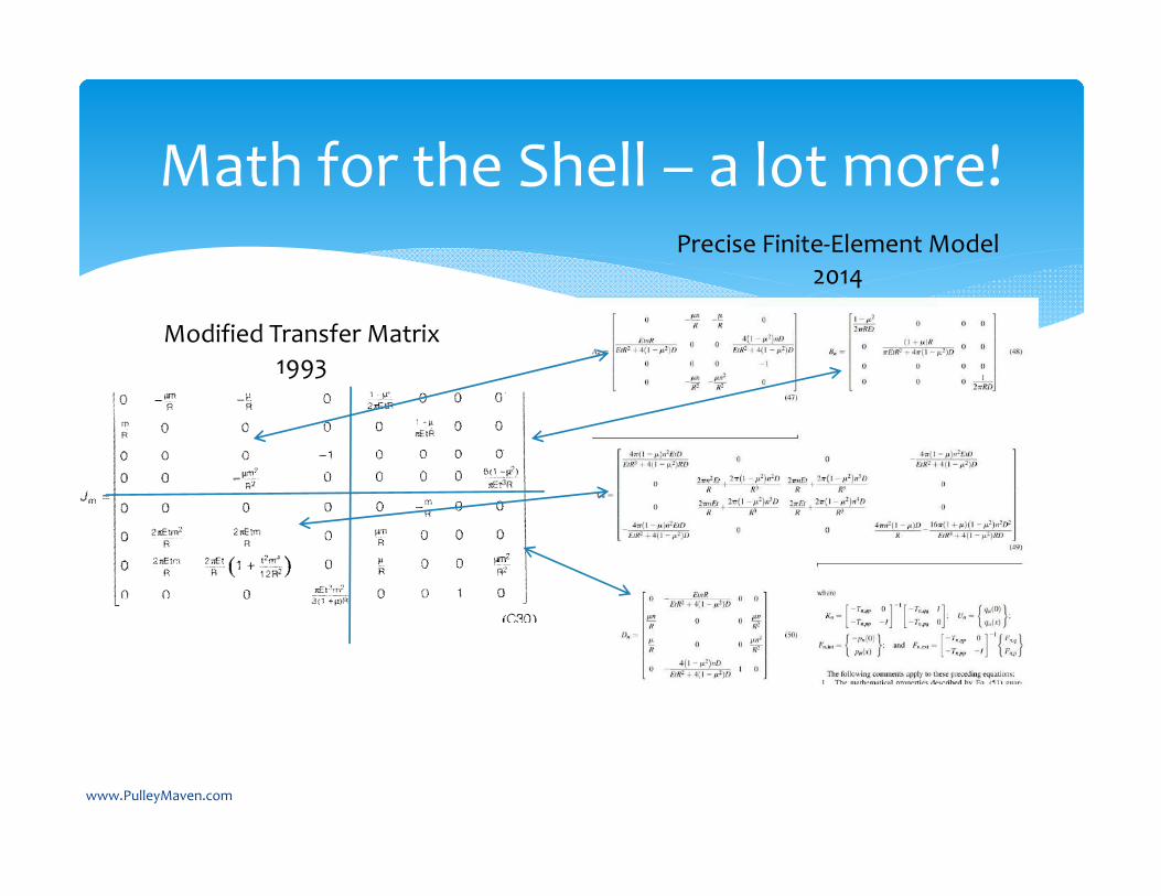
Math for the Shell – a lot more!
Modified Transfer Matrix1993
Precise Finite‐Element Model2014
www.PulleyMaven.com
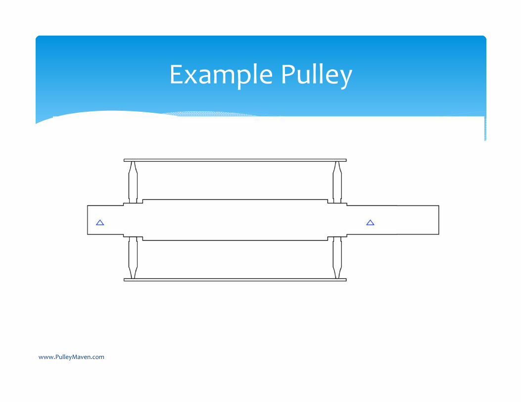
Example Pulley
www.PulleyMaven.com
www.PulleyMaven.com

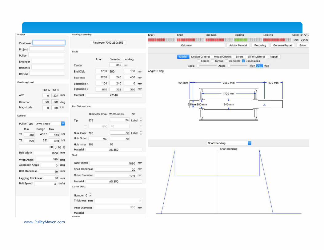
Shaft Dimensions
www.PulleyMaven.com
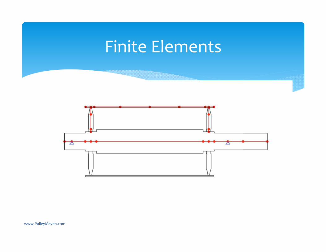
Finite Elements
www.PulleyMaven.com
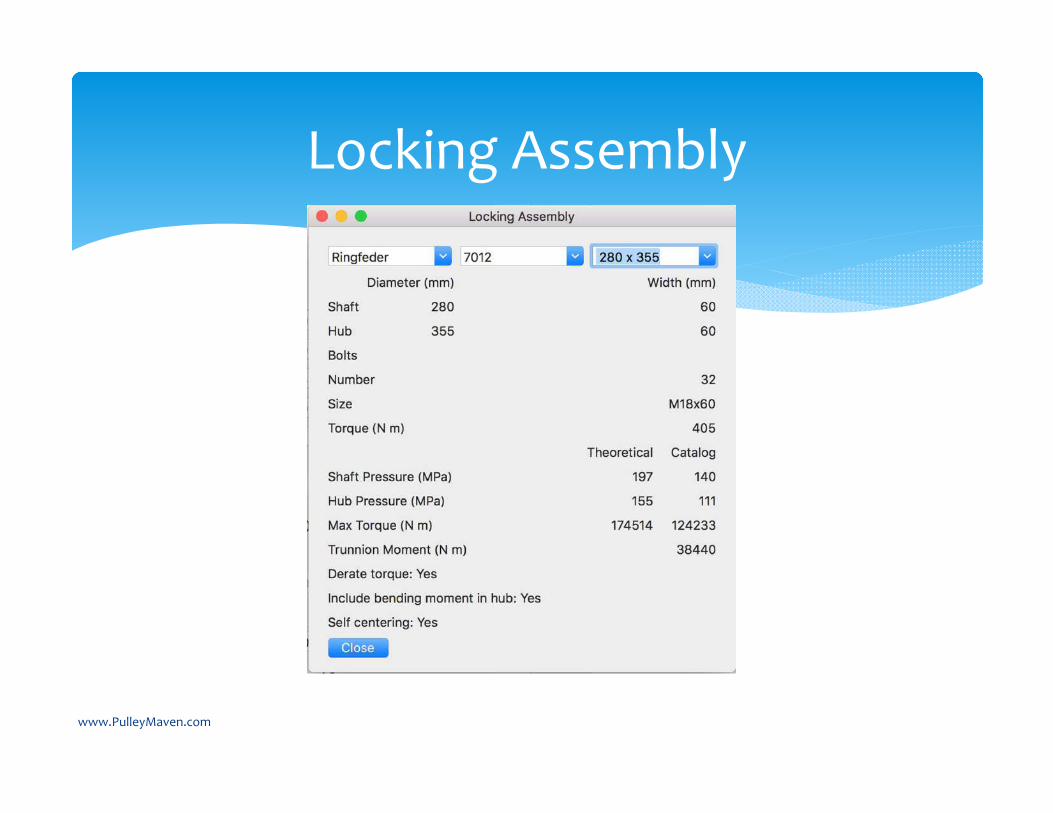
Locking Assembly
www.PulleyMaven.com
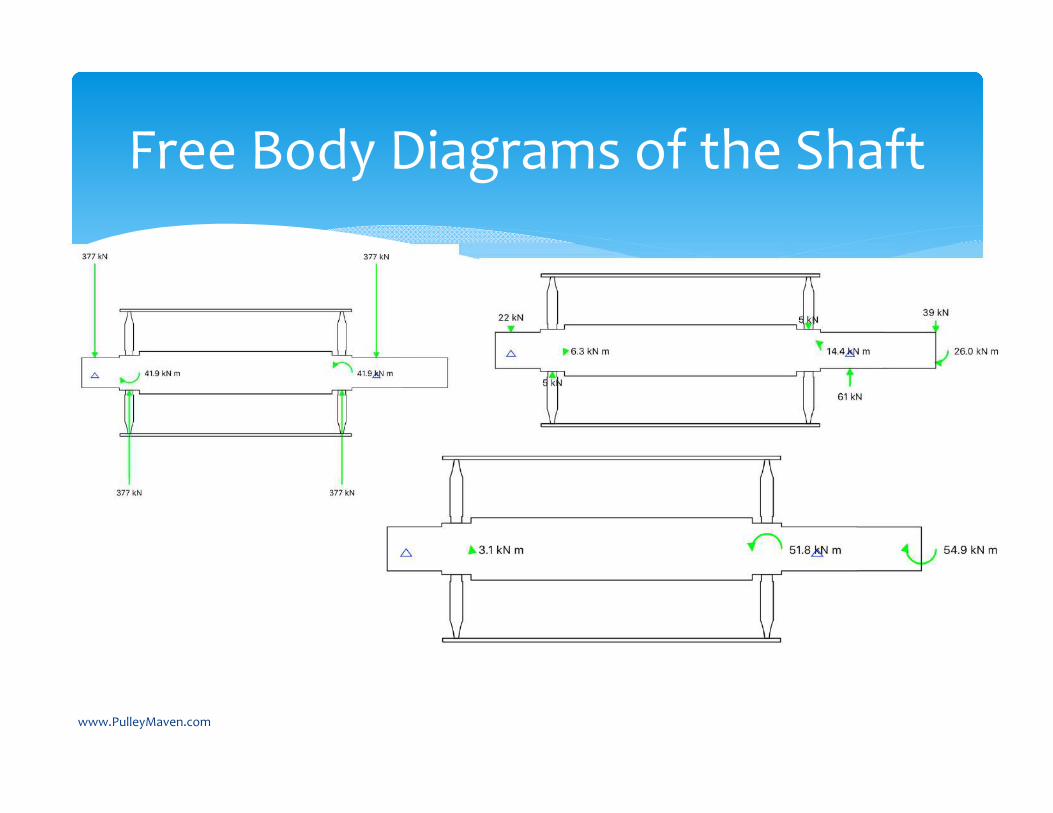
Free Body Diagrams of the Shaft
www.PulleyMaven.com
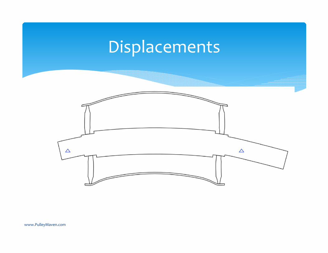
Displacements
www.PulleyMaven.com
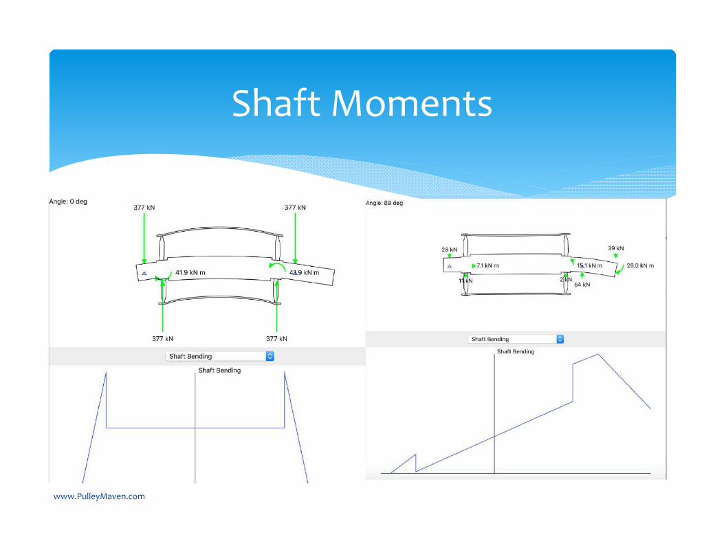
Shaft Moments
www.PulleyMaven.com
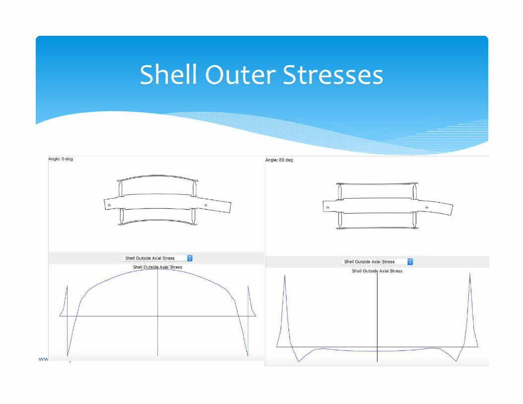
Shell Outer Stresses
www.PulleyMaven.com

3D Displacements
www.PulleyMaven.com
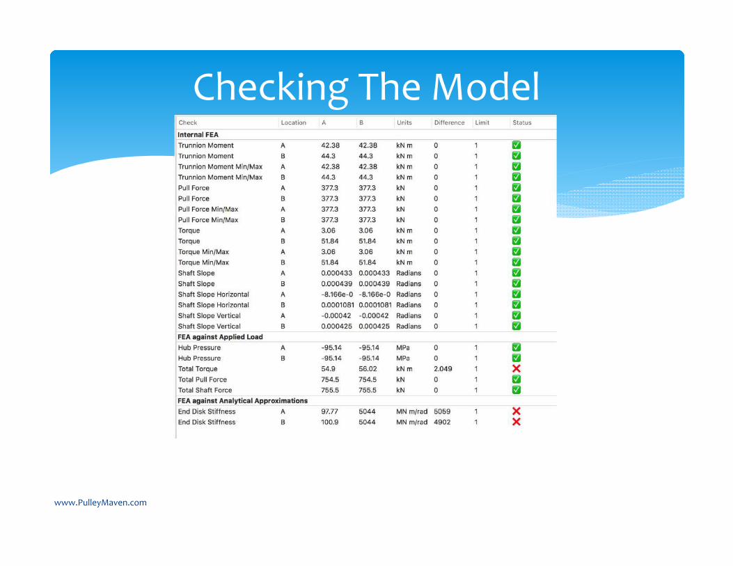
Checking The Model
www.PulleyMaven.com
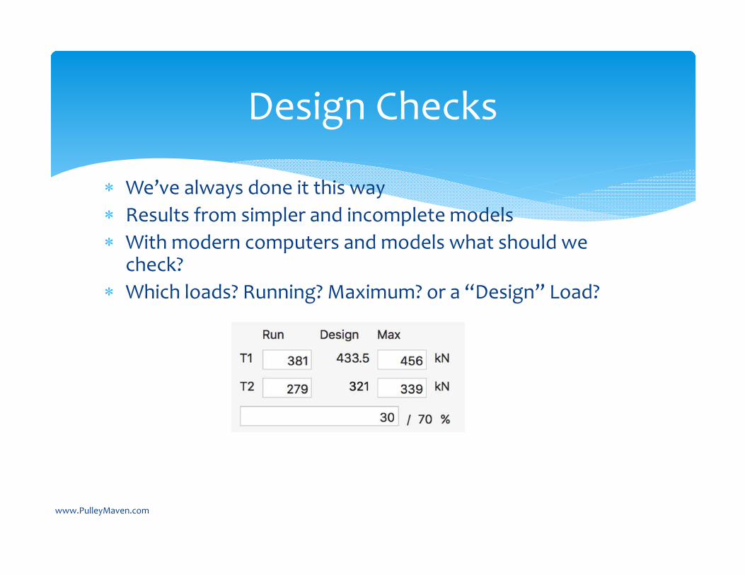
We’ve always done it this way Results from simpler and incomplete models With modern computers and models what should we
check? Which loads? Running? Maximum? or a “Design” Load?
Design Checks
www.PulleyMaven.com

Design Criteria
www.PulleyMaven.com
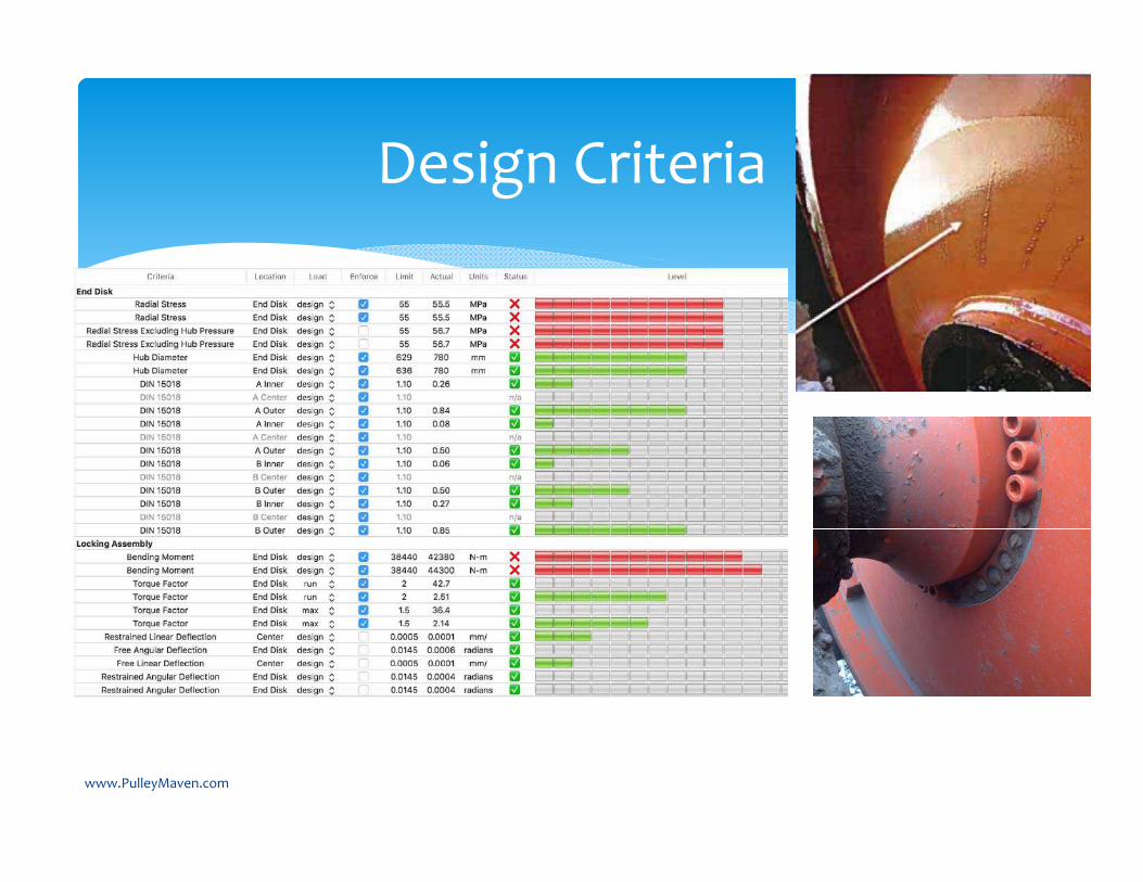
Design Criteria
www.PulleyMaven.com

Next Steps – Bill of Material and Operations
www.PulleyMaven.com

Next Steps – Solver & Design Optimization
www.PulleyMaven.com
Objective: Lowest Cost, Lightest Weight, Standardized
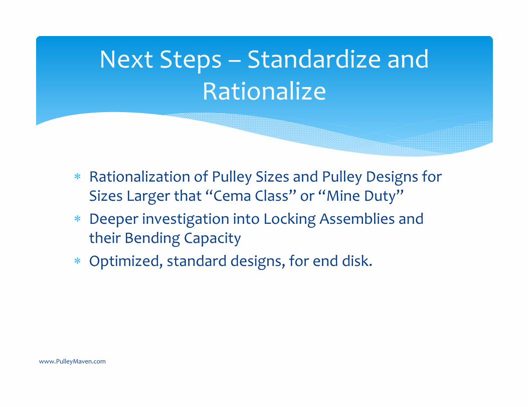
Rationalization of Pulley Sizes and Pulley Designs for Sizes Larger that “Cema Class” or “Mine Duty”
Deeper investigation into Locking Assemblies and their Bending Capacity
Optimized, standard designs, for end disk.
www.PulleyMaven.com
Next Steps – Standardize and Rationalize

Why not just use a commercial FEA package like Ansys?
It’s REALLY hard to get right. You need to have very advanced FEA skills.
Once you get the results you have stresses and strains at a bunch of points but now need to consider fatigue as it rotates and apply design standards.
Image from Lorbrand website.www.PulleyMaven.com
The pressure from modern locking assemblies influences the stresses in the pulley shell.
Locking assembly manufactures don’t calculate the hub and shaft pressures the same way. Some are not conservative!
The end disk equations of Lange and Schmoltzi don’t handle, high tension, small diameter pulley very well.
Many “traditional” design criteria need to be forgotten. In many cases they limit modern design options.
www.PulleyMaven.com
Conclusions
Outline
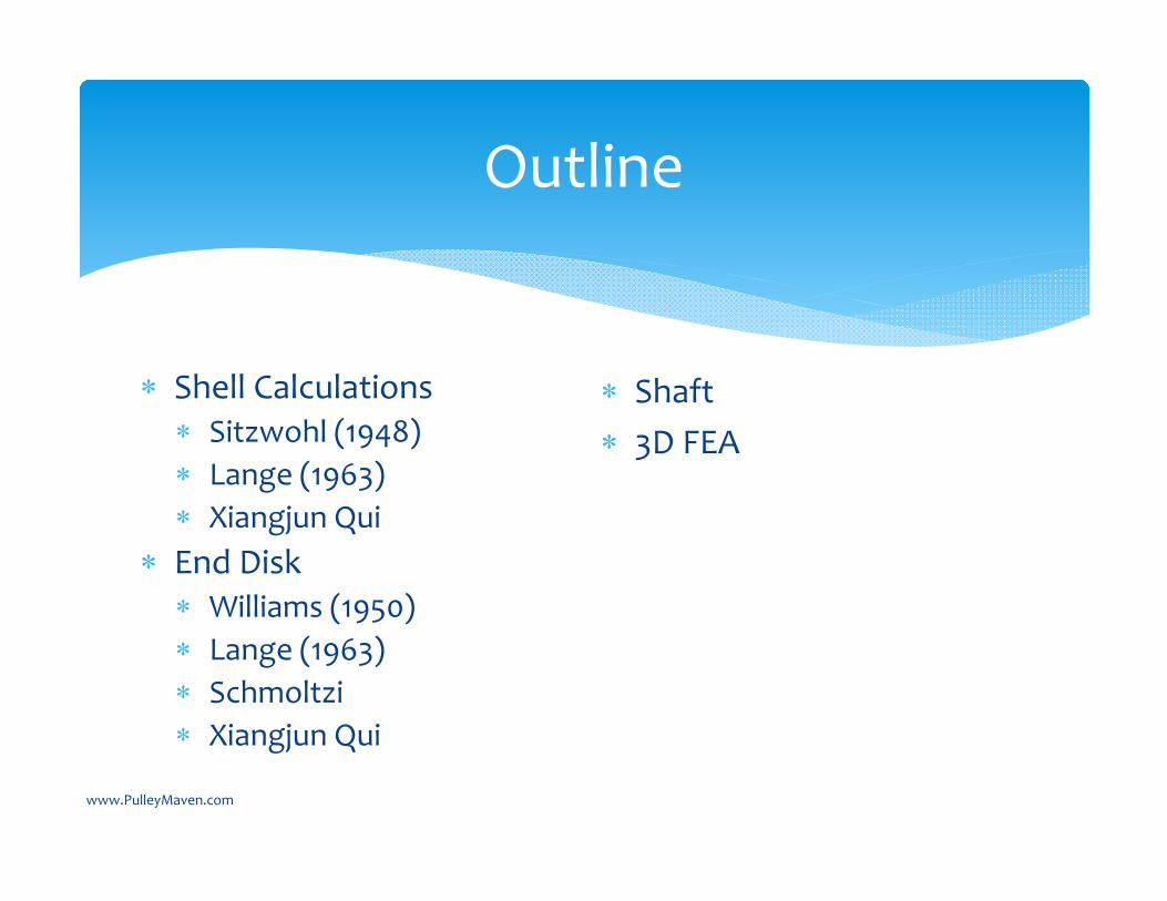
Shell Calculations Sitzwohl (1948) Lange (1963) Xiangjun Qui
End Disk Williams (1950) Lange (1963) Schmoltzi Xiangjun Qui
Shaft 3D FEA
www.PulleyMaven.com
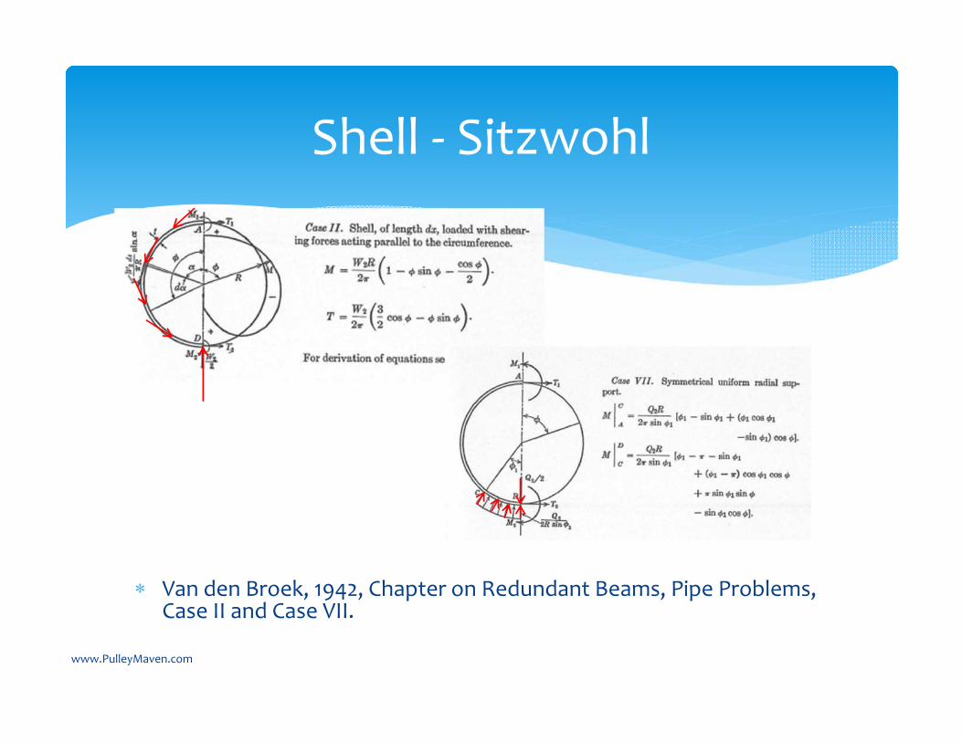
Van den Broek, 1942, Chapter on Redundant Beams, Pipe Problems, Case II and Case VII.
Shell ‐ Sitzwohl
www.PulleyMaven.com
Sitzwohl, Josef, Welded Conveyor Pulleys – Analysis of Stresses in Pulley Shell, 1948, Australia. (Available on Amazon)
Also know as the “Link‐Belt” method in the USA. Fabrica de Aço Paulista S.A. (Faço), Manual de Transportadores Continuos, 1978, Brazil.
Golka, et. al., Belt Conveyor Principles for Calculation and Design, 2007, Australia.
Used today by …Google “Sitzwohl Pulley”
Shell ‐ Sitzwohl
www.PulleyMaven.com
Simple. Can be reduced to a table and a hand calculation.
Treats cylinder as infinitely long – i.e. a loaded ring Only considers tangential bending stress in the shell. Also reference: Roark, 1938 (1,2,34, editions) Table VIII, Case 15 and 25 Van den Broek, 1942, Chapter on Redundant Beams,
Pipe Problems, Case II and Case VII.
Shell ‐ Sitzwohl
www.PulleyMaven.com
Short comings Not very accurate. Uniform loading, does not handle different T1 and T2,
and shear force on the pulley. Does not consider bending stress in the axial direction. Does not consider any interaction with the end disk. Does not accommodate internal stiffening disks.
Shell Sitzwohl
www.PulleyMaven.com
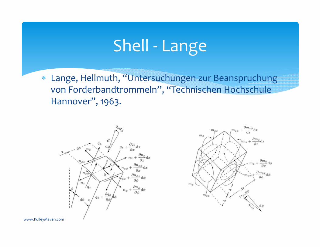
Lange, Hellmuth, “Untersuchungen zur Beanspruchungvon Forderbandtrommeln”, “Technischen HochschuleHannover”, 1963.
Shell ‐ Lange
www.PulleyMaven.com
“Moment Theory of Circular Cylindrical Shells” Complicated, intricate, advanced math. Helpful to read Girkmann, 1963 and Flugge, 1960 to
understand the Lange Shell equations. After a lot of math, a bit of “luck”, for a set of boundary
conditions favorable for pulleys an exact solution is available.
The boundary conditions are that at the end disk there is no moment, axial force, or radial deformation.
Shell ‐ Lange
www.PulleyMaven.com
For 1963 this was very advanced numerical modeling work. Computers were in their infancy so a lot of focus on simplifying
the results. Assumed that “critical” conveyor would have a wrap of 180
degrees so provided simplifications with this assumption. For the pulley shell smaller or larger wrap angles have higher stresses so this is not a good simplification to follow.
Ringfeder locking assemblies were also just starting to be used. However, pressures were much lower, diameters much larger, and their impact on shell stresses not considered.
Several companies use pulley models based on Lange – primarily in Europe and Australia.
Shell Lange
www.PulleyMaven.com
Shell Lange
Advantages
Considers the tangential, axial, and shear stresses in the shell.
Good agreement with strain gauge measurements and FEA results in the center of the shell.
With todays computers equations can be solved instantly. No need for some of the Lange and Schmoltzisimplifications.
Disadvantages
Need a computer program to solve. Does not accommodate center
disks. Load applied at the midplane on the
shell. (Not shell surface, lagging surface, or belt carcass midplane)
Does not consider influence of the end disk and locking assembly.
www.PulleyMaven.com
End Disk
“Simple Pulley Design”
Good to explain the concept of “Rigid” versus “Flexible” end disk design.
Good to explain the bending moment load sharing between the end disk and shaft.
Not applicable today except possible for small, light duty pulleys.
Lange / Schmoltzi“Turbine” End Disk
For large diameter, smaller hub, pulleys a reasonable choice.
Using for small diameter, wide, high tension, high pressure locking assembly pulleys leads to a lot of uncertainty.
www.PulleyMaven.com
Related Documents