International Research Journal of Engineering and Technology (IRJET) e-ISSN: 2395-0056 Volume: 08 Issue: 07 | July 2021 www.irjet.net p-ISSN: 2395-0072 © 2021, IRJET | Impact Factor value: 7.529 | ISO 9001:2008 Certified Journal | Page 3125 DESIGN AND ANALYSIS OF CONNECTING ROD USING COMPOSITE MATERIALS AND ALLOYS Mr. Sumukh. R 1 , Mr. Sankalp Khobragade 2 , Mr. Vishwaradya Patil 3 , Mr. Vishwas K 4 , Mr. Hemanth Kumar J 5 1 Mr. Sumukh .R: Student, Department of Mechanical Engineering, PESIT-BSC, Bengaluru, Karnataka. 2 Mr. Mr. Sankalp Khobragade: Student, Dept. of Mechanical Engineering, PESIT-BSC, Bengaluru, Karnataka. 3 Mr. Vishwaradya Patil: Student, Department of Mechanical Engineering, PESIT-BSC, Bengaluru, Karnataka. 4 Mr. Vishwas K: Student, Department of Mechanical Engineering, PESIT-BSC, Bengaluru, Karnataka. 5 Mr. Hemanth Kumar J: Assistant Professor, Dept. of Mechanical Engineering, PESIT-BSC, Bengaluru, Karnataka. ---------------------------------------------------------------------***---------------------------------------------------------------------- Abstract - The connecting rod is the intermediate member between the piston and the Crankshaft. Its primary function is to transmit the push and pull from the piston pin to the crank pin, thus converting the reciprocating motion of the piston into rotary motion of the crank. Most common cases of failure of Connecting Rod are of Tensile Failure, which happens due to high engine speeds, or Casting Defect, which develops due to cyclic load behavior. This project aims to replace the typical convention material used for manufacturing connecting rod like Steel, so as to improve the performance parameters while reducing the overall weight of the component. This study aims on comparing a connecting rod of standard dimensions and made up of convention material like Steel with that made up of composite materials like Aluminum-Beryllium Alloy, Aluminum-Silicon Carbide Composite and Titanium Alloy. The Shape and the Materials have been selected based on the Strength and Stiffness Criteria. The project also performed Static Structural parameters like Von-Mises Stress, Deformation, Factor of safety and Buckling Analysis of standard connecting rod design using FEM on a commercial software ANSYS workbench, to predict structural strength and buckling limit of the model. Key Words: Connecting rod, Aluminum Silicon Carbide composite, Steel, Aluminum Beryllium alloy, Titanium alloy, Strength to weight ratio. 1.INTRODUCTION Connecting Rod converts the reciprocating motion of piston into rotary motion of the crank shaft. It connects the crank and the piston and thus transfer the power for the movement of the vehicle. Since, it converts the linear motion of piston into rotary motion of the crankshaft, it undergoes following kinds of loads and stresses like bending, tension, compression and buckling. The bigger end of the connecting rod connects the crank shaft with the help of crank pin with a plain bearing. The smaller end is connected to piston through piston pin. “ “Connecting Rod is the part of IC engine that is under high stress most of the time, hence it is more prone to failure under unfavourable conditions. An ideal Connecting Rod should have minimal weight and cost effective, but also should be strong enough to withstand high stresses and high cycle fatigue. In the past years, research based on connecting rod has shifted from materials having uniform composition to many other metal alloys and composite materials for enhancement of performance, strength and stiffness, reduction of weight, wear and corrosion resistance, and also for reducing the thermal expansion. Metal Matrix Composites (MMCs), Aluminum-Silicon Carbide Composite and many metal alloys meets the requirements for applications requiring combined strength, thermal conductivity, and low coefficient of thermal expansion with lower density to reduce the weight of the connecting rod and increase the efficiency of the engine. Fig -1: Connecting rod “Based on the shape of the cross section of the connecting rod they are classified mainly into four categories: 1. I - section 2. H - section 3. Rectangular section 4. Circular section“ “Among these cross-sections circular and rectangular cross sections are the most stressed cross sections. Hence these shapes are ruled out of our analysis. The other two sections had less stress concentrations and showed better results. But I-section has better shape factor in bending both due to strength and stiffness effect. Hence I-section is

Welcome message from author
This document is posted to help you gain knowledge. Please leave a comment to let me know what you think about it! Share it to your friends and learn new things together.
Transcript

International Research Journal of Engineering and Technology (IRJET) e-ISSN: 2395-0056
Volume: 08 Issue: 07 | July 2021 www.irjet.net p-ISSN: 2395-0072
© 2021, IRJET | Impact Factor value: 7.529 | ISO 9001:2008 Certified Journal | Page 3125
DESIGN AND ANALYSIS OF CONNECTING ROD USING COMPOSITE
MATERIALS AND ALLOYS
Mr. Sumukh. R1, Mr. Sankalp Khobragade2, Mr. Vishwaradya Patil3, Mr. Vishwas K4,
Mr. Hemanth Kumar J5
1Mr. Sumukh .R: Student, Department of Mechanical Engineering, PESIT-BSC, Bengaluru, Karnataka. 2Mr. Mr. Sankalp Khobragade: Student, Dept. of Mechanical Engineering, PESIT-BSC, Bengaluru, Karnataka. 3Mr. Vishwaradya Patil: Student, Department of Mechanical Engineering, PESIT-BSC, Bengaluru, Karnataka.
4Mr. Vishwas K: Student, Department of Mechanical Engineering, PESIT-BSC, Bengaluru, Karnataka. 5Mr. Hemanth Kumar J: Assistant Professor, Dept. of Mechanical Engineering, PESIT-BSC, Bengaluru, Karnataka.
---------------------------------------------------------------------***----------------------------------------------------------------------
Abstract - The connecting rod is the intermediate member between the piston and the Crankshaft. Its primary function is to transmit the push and pull from the piston pin to the crank pin, thus converting the reciprocating motion of the piston into rotary motion of the crank. Most common cases of failure of Connecting Rod are of Tensile Failure, which happens due to high engine speeds, or Casting Defect, which develops due to cyclic load behavior. This project aims to replace the typical convention material used for manufacturing connecting rod like Steel, so as to improve the performance parameters while reducing the overall weight of the component. This study aims on comparing a connecting rod of standard dimensions and made up of convention material like Steel with that made up of composite materials like Aluminum-Beryllium Alloy, Aluminum-Silicon Carbide Composite and Titanium Alloy. The Shape and the Materials have been selected based on the Strength and Stiffness Criteria. The project also performed Static Structural parameters like Von-Mises Stress, Deformation, Factor of safety and Buckling Analysis of standard connecting rod design using FEM on a commercial software ANSYS workbench, to predict structural strength and buckling limit of the model.
Key Words: Connecting rod, Aluminum Silicon Carbide composite, Steel, Aluminum Beryllium alloy, Titanium alloy, Strength to weight ratio.
1.INTRODUCTION
Connecting Rod converts the reciprocating motion of piston into rotary motion of the crank shaft. It connects the crank and the piston and thus transfer the power for the movement of the vehicle. Since, it converts the linear motion of piston into rotary motion of the crankshaft, it undergoes following kinds of loads and stresses like bending, tension, compression and buckling. The bigger end of the connecting rod connects the crank shaft with the help of crank pin with a plain bearing. The smaller end is connected to piston through piston pin. “
“Connecting Rod is the part of IC engine that is under high
stress most of the time, hence it is more prone to failure
under unfavourable conditions. An ideal Connecting Rod should have minimal weight and cost effective, but also should be strong enough to withstand high stresses and high cycle fatigue. In the past years, research based on connecting rod has shifted from materials having uniform composition to many other metal alloys and composite materials for enhancement of performance, strength and stiffness, reduction of weight, wear and corrosion resistance, and also for reducing the thermal expansion. Metal Matrix Composites (MMCs), Aluminum-Silicon Carbide Composite and many metal alloys meets the requirements for applications requiring combined strength, thermal conductivity, and low coefficient of thermal expansion with lower density to reduce the weight of the connecting rod and increase the efficiency of the engine.
Fig -1: Connecting rod
“Based on the shape of the cross section of the connecting
rod they are classified mainly into four categories: 1. I - section 2. H - section 3. Rectangular section 4. Circular section“ “Among these cross-sections circular and rectangular
cross sections are the most stressed cross sections. Hence these shapes are ruled out of our analysis. The other two sections had less stress concentrations and showed better results. But I-section has better shape factor in bending both due to strength and stiffness effect. Hence I-section is
International Research Journal of Engineering and Technology (IRJET) e-ISSN: 2395-0056
Volume: 08 Issue: 07 | July 2021 www.irjet.net p-ISSN: 2395-0072
© 2021, IRJET | Impact Factor value: 7.529 | ISO 9001:2008 Certified Journal | Page 3126
preferred for the design of connecting rod out of these cross-sections.“
2. LITERATURE SURVEY This section deals with the literature papers related to our project that have been studied to gain an insight into the
material selection criteria for connecting rod.
1. A. Pandiyan, et al. [1], has carried out analysis based on Aluminium alloys and composites and concluded that the materials used is having high hardness, strength and also durability. A1 6061-T6 material connecting rod will reduce the weight up to 7.98% when compared with ADC12 keeping the strength to weight ratio and ductility same. This conclusion is drawn on the basis of topology optimization methodology.
2. Shubham Tiwari, et al. [2], focuses on optimum
shape, manufacturing process for better material properties and the suitable alloys and composites for connecting rod. Powder Metallurgy was studied and it was found that it strengthens the microstructure and better mechanical property of connecting rod can be obtained. They inferred that if instead of Steel we use Titanium Alloy to manufacture Connecting Rod using this method then tensile elongation of connecting road and tensile strength can be enhanced to a greater extent.
3. Vikas Singh, et al. [3], have used ANSYS software for
force, stress and strain analysis for different materials and compared them with each other. When boundary conditions are applied on connecting rod, using finite element analysis the unknown variables such as deformation, strain and stress are found. The solution was obtained for Equivalent Elastic Strain and Total deformation using different materials one after the other.
4. Somnath Chattopadhyay [4] has done the required
basic calculations for the selection of the material and also provided information about suitable manufacturing process for different materials.
5. Adnan Ali Haider, et al. [5], concluded that the
Titanium Alloy suites best for manufacturing of Connecting Rod. As because it has the best Factor of Safety with regard to its weight and minimum deformation. This was followed by Aluminium Alloy 7075-T6, which had lower Factor of Safety as compared to Titanium Alloy, but the weight was much lower than that of the Titanium Alloy.
6. Kuldeep B. [6], has done the assembly of connecting
rod with carbon Steel, but nowadays, they are done
using aluminium alloys. In this study, they replaced connecting rod by using aluminium based composite material which has been reinforced with silicon carbide and fly ash. They also conducted finite element analysis considering two materials the parameters like the stress and strain and the displacement was acquired from ANSYS software. “
7. Ashby, M. F., et al. [7], as looked at the reforming the
connecting rod made of Steel and have arrived at the list of processes, that is - (1) Die casting (2) forging and machining (3) powder methods and machining. They have discovered that for a production of ten thousand components, forging comes out the cheapest then followed by dicasting. Powder methods are comparatively costlier because slow production cost and capital cost.
8. Mr. H D. Nitturkar, “et al. [8], noticed that the
minimum stress among all loading conditions was seen at the crank and the piston end. Therefore, material was reduced from these resulting in reduction cost.”
9. Pravardhan S. Shenoy, “et al. [9], Al introduced the
finite element analysis procedure for improving the connection rod weight and cost reduction. A study was conducted on connecting rod made forged Steel with a thought of improving the weight and production cost. Weight was reduced by an iterative procedure this study resulted in new connecting rod was ten percent lighter and twenty-five percent less expensive when compared to the existing connecting rod. “
3. RESEARCH GAP Previously the materials used for analysis were Aluminium Alloys and Composites and currently the material used is Steel. There are still many more combinations of materials left to be explored and their impact to the industry is still unknown. After referring to numerous journals, we decide to carry forward our project using, Aluminum-Beryllium Alloy, Titanium Alloy and Aluminum-Silicon Carbide Composite, based on which, Force Analysis will be carried out using the ANSYS software.
4. OBJECTIVES
1. Increasing the efficiency of the engine by reducing the weight of the connecting rod.
2. Increasing the strength and stiffness of the connecting rod.
3. Increasing the durability of connecting rod.
International Research Journal of Engineering and Technology (IRJET) e-ISSN: 2395-0056
Volume: 08 Issue: 07 | July 2021 www.irjet.net p-ISSN: 2395-0072
© 2021, IRJET | Impact Factor value: 7.529 | ISO 9001:2008 Certified Journal | Page 3127
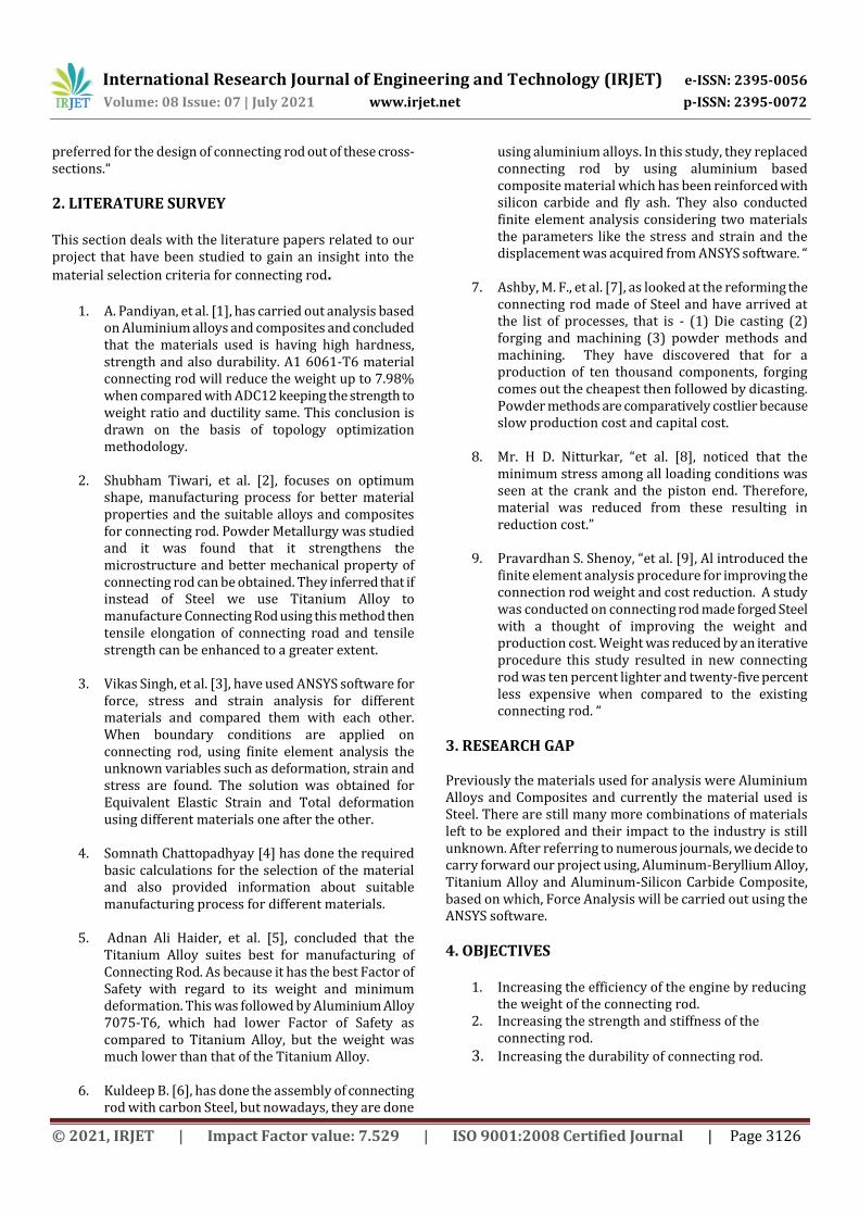
5. METHODOLOGY This section gives a brief description about the methodology followed to complete this project. The following flowchart represents the methodology process:
ANALYSIS OF THE
MODEL
SELECTION OF MATERIAL
Fig -2: Methodology Flowchart
6. DESIGN CALCULATIONS
For calculations of force acting on piston, the following parameters have been considered :
a) Engine Specifications: 150 cc, 4-stroke, air cooled Petrol Engine
b) Bore Diameter × Stroke Length = 57 × 58.6 c) Stroke Volume = 149 cc d) Maximum Power = 11.9 bhp @ 7500 rpm e) Maximum Torque = 12.8 N-m @ 6000 rpm f) Compression Ratio = 9.5:1 g) Molecular Weight, Me = 114.228 g/mole h) Universal Gas Constant, R = 8.314 J/mol-K Factor of Safety is assumed to be 2. Stroke Length = 58.6 mm. Crank Radius = L/2 = 29.3 mm. Frictional Forces are neglected. Connecting Rod Length to Crank Radius is 4:1 (for
IC Engines).
I-section has more shape factor compared to H-section and also bending strength is more, hence I-section is being considered for analysis.
For I-section calculations, these are the standard parameters:
Thickness of Connecting Rod = t Height, H = 5t Width of flange, B = 4t I – Section Area = 11t2
Gas Pressure on Piston and Buckling Load Calculations: PV = me × Rspecific × T
P =
me = 0.109 ≈ 0.11 kg
P =
P = 15.48 MPa ≈ 15.5 MPa
Fg = P (dB)2,
Fg = 16 (57)2
Fg = 39.552 kN
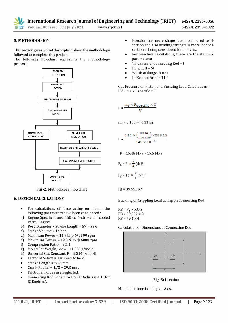
Buckling or Crippling Load acting on Connecting Rod: FB = Fg × F.O.S FB = 39.552 × 2 FB = 79.1 kN Calculation of Dimensions of Connecting Rod:
Fig -3: I-section
Moment of Inertia along x – Axis,
International Research Journal of Engineering and Technology (IRJET) e-ISSN: 2395-0056
Volume: 08 Issue: 07 | July 2021 www.irjet.net p-ISSN: 2395-0072
© 2021, IRJET | Impact Factor value: 7.529 | ISO 9001:2008 Certified Journal | Page 3128
Ixx =1/12 [4t×(5t^3 )-3t×(t^3)] Ixx = 34.91 t4
Moment of Inertia along y – Axis,
Iyy = 1/12 [2×t×4 (t)×3+(3t^4)] Iyy = 10.917 t4
⸫ = 3.2
Since the connecting rod to crank radius is 4:1, the length of the connecting rod is: L = 29.3 × 4 = 117.2 ≈ 118 mm
Thickness of I-section: From Rankine’s formula
=
σc = 320 MPa (crushing strength) K = 4/25000 for Steel rod, pin connected at both ends so that the rod is freely bends in any plane
k = (Radius of gyration for an I-section)
k = 3.174 t2 A = 11 t2 Substituting the values in the Rankine’s formula:
=
t = 4.74 ≈ 4.8 mm
Width of I-section: B = 4t B = 19.2 mm Height of I-section: H = 5t H = 24 mm Height at the bigger end = 1.1 H = 26 mm
Height at the smaller end = 0.82 H = 19.68 ≈ 20 mm Length of the bearing at smaller end, l1 = 0.5 D, (where D is the diameter of the piston) l1 = 0.5 × 57 l1 = 28.5 ≈ 29 mm Ratio of length to piston pin diameter at small end,
l1/d = 29/1.5 (for Petrol Engines) = 19.33 mm
Outer Diameter at Piston End = 1.8 d
= 1.8 × 19.4 = 34.92 ≈ 35 mm
Diameter of Crank Pin = dp1 = 0.67 D
= 0.67 × 57 = 39 mm
Length of the Crank Pin Bearing, lp1 = dp1
lp1 = 39 mm Outer Diameter at Crank End = 1.5 × dp1
= 1.5 × 39 = 62.5 ≈ 63 mm
Table -1: Dimensions of Connecting Rod
S. No. Parameters (mm)
1. Thickness of Connecting Rod = 4.8 mm
2. Width of the section = 19.2 mm
3. Height of the Section = 24 mm
4. Height at the bigger end = 26 mm
5. Height at the smaller end = 20 mm
6. Inner Diameter at Piston End = 19.4 mm
7. Outer Diameter at the Piston End = 35 mm
8. Inner Diameter at Crank End = 39 mm
9. Outer Diameter at Crank End = 63 mm
7. MATERIAL SELECTION AND PROPERTIES The material selected are based on it’s strength to wight ratio i.e., with the intention of increasing the strength simultaneously reducing the weight. The materials selected are Titanium alloy, Aluminum Beryllium alloy and Aluminum Silicon carbide composite and the results from the analysis of these materials are compared with the standard
International Research Journal of Engineering and Technology (IRJET) e-ISSN: 2395-0056
Volume: 08 Issue: 07 | July 2021 www.irjet.net p-ISSN: 2395-0072
© 2021, IRJET | Impact Factor value: 7.529 | ISO 9001:2008 Certified Journal | Page 3129
connecting rod material which is carbon steel. The properties of the materials are mentioned in the table below:
Table -2: Material Properties
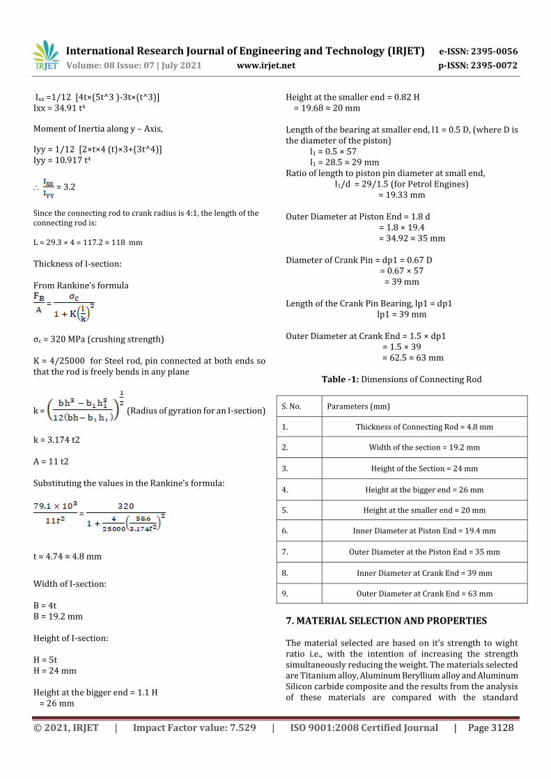
8. MODELLING AND ANALYSIS Modelling a mechanical part is the first basic step of the analysis process, which will later help us to virtually simulate how each and every section of the connecting rod will perform under specified circumstances. In order to create a standard model of Connecting Rod, CATIA V5 modelling software was used. CATIA stands for Computer Aided Three-Dimensional Interactive Application. CATIA is a highly sophisticated and globally recognised product design software, developed and created by Dassault Systemes. a multinational software company based out of France. CATIA is widely used to create 3D design, to evaluate computer-aided engineering solutions, implement PLM, and establish computer-aided manufacturing solutions. The software is commonly used in manufacturing industries and Original Equipment Manufacturers (OEMs) to increase designing, analysing, and managing new products. It's much more than a CAD (Computer Aided Design) software package. It's a full software suite which incorporates CAD, CAE (Computer-Aided Engineering) and CAM (Computer-Aided Manufacture). Due to its complexity and versatility, it has been known as the leading industry standard software to carry out highly complex simulations.
Fig -4: CATIA V5 interface
Before modelling the connecting rod, it is necessary to find out the standard dimensions of it. Hence by considering all the assumptions, suitable design calculations need to done and the theoretical loads acting on the connecting rod needs to be calculated. After gathering all the necessary data, a standard connecting rod model can be created on CATIA V5
modelling software.
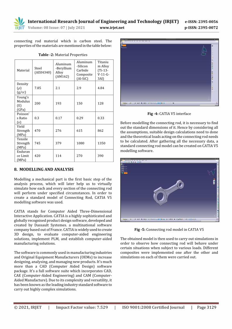
Fig -5: Connecting rod model in CATIA V5 The obtained model is then used to carry out simulations in order to observe how connecting rod will behave under certain situations when subject to various loads. Different composites were implemented one after the other and simulations on each of them were carried out.
Material Steel (AISI4340)
Aluminum-Beryllium Alloy (AM162)
Aluminum-Silicon Carbide Composite (Al-SiC)
Titanium Alloy (Ti-13-V-11-G-3Al)
Density (𝜌) (g/cc)
7.85 2.1 2.9 4.84
Young's Modulus (E) (GPa)
200 193 150 128
Poisson's Ratio (𝜐)
0.3 0.17 0.29 0.33
Yield Strength (MPa)
470 276 615 862
Tensile Strength (MPa)
745 379 1080 1350
Endurance Limit (MPa)
420 114 270 390
International Research Journal of Engineering and Technology (IRJET) e-ISSN: 2395-0056
Volume: 08 Issue: 07 | July 2021 www.irjet.net p-ISSN: 2395-0072
© 2021, IRJET | Impact Factor value: 7.529 | ISO 9001:2008 Certified Journal | Page 3130
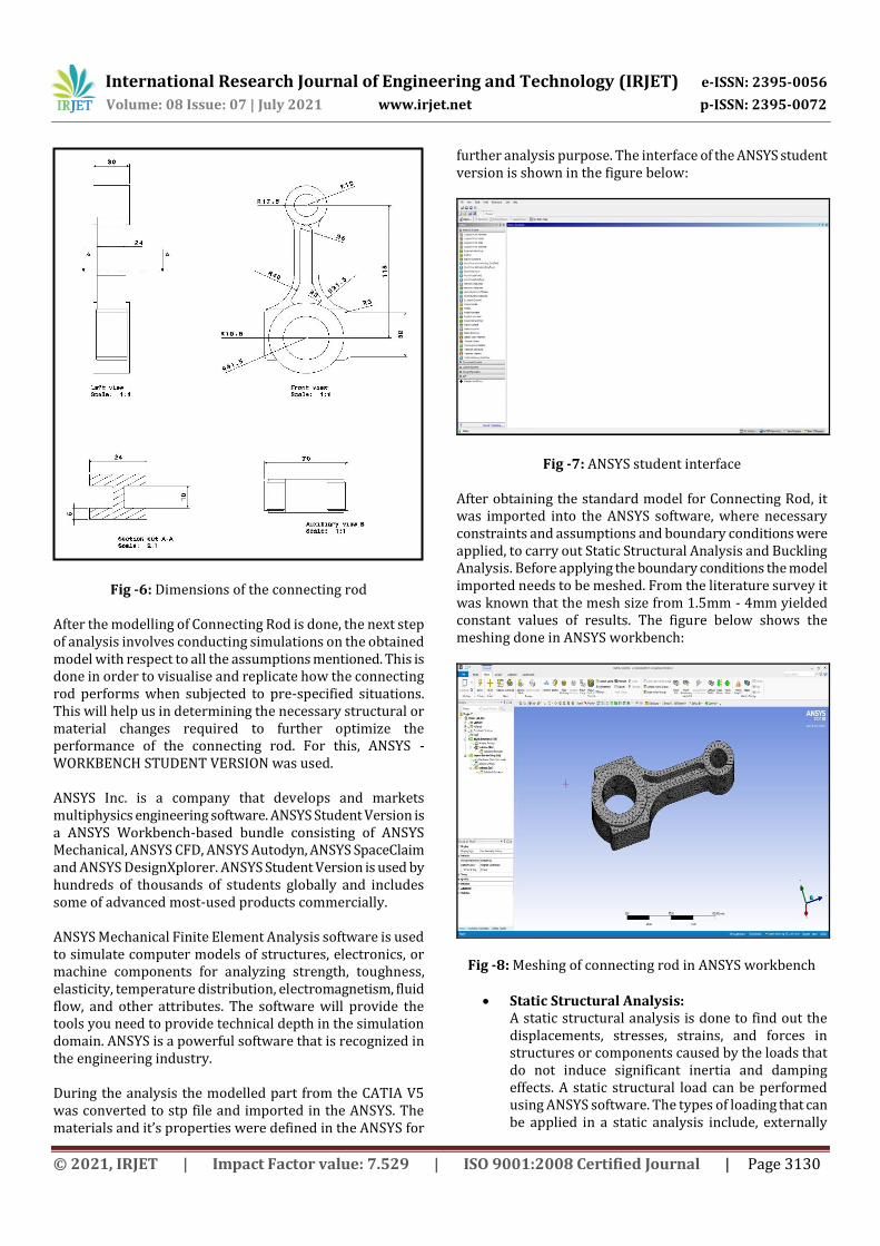
Fig -6: Dimensions of the connecting rod
After the modelling of Connecting Rod is done, the next step of analysis involves conducting simulations on the obtained model with respect to all the assumptions mentioned. This is done in order to visualise and replicate how the connecting rod performs when subjected to pre-specified situations. This will help us in determining the necessary structural or material changes required to further optimize the performance of the connecting rod. For this, ANSYS - WORKBENCH STUDENT VERSION was used. ANSYS Inc. is a company that develops and markets multiphysics engineering software. ANSYS Student Version is a ANSYS Workbench-based bundle consisting of ANSYS Mechanical, ANSYS CFD, ANSYS Autodyn, ANSYS SpaceClaim and ANSYS DesignXplorer. ANSYS Student Version is used by hundreds of thousands of students globally and includes some of advanced most-used products commercially. ANSYS Mechanical Finite Element Analysis software is used to simulate computer models of structures, electronics, or machine components for analyzing strength, toughness, elasticity, temperature distribution, electromagnetism, fluid flow, and other attributes. The software will provide the tools you need to provide technical depth in the simulation domain. ANSYS is a powerful software that is recognized in the engineering industry. During the analysis the modelled part from the CATIA V5 was converted to stp file and imported in the ANSYS. The materials and it’s properties were defined in the ANSYS for
further analysis purpose. The interface of the ANSYS student version is shown in the figure below:
Fig -7: ANSYS student interface After obtaining the standard model for Connecting Rod, it was imported into the ANSYS software, where necessary constraints and assumptions and boundary conditions were applied, to carry out Static Structural Analysis and Buckling Analysis. Before applying the boundary conditions the model imported needs to be meshed. From the literature survey it was known that the mesh size from 1.5mm - 4mm yielded constant values of results. The figure below shows the meshing done in ANSYS workbench:
Fig -8: Meshing of connecting rod in ANSYS workbench
Static Structural Analysis: A static structural analysis is done to find out the displacements, stresses, strains, and forces in structures or components caused by the loads that do not induce significant inertia and damping effects. A static structural load can be performed using ANSYS software. The types of loading that can be applied in a static analysis include, externally
International Research Journal of Engineering and Technology (IRJET) e-ISSN: 2395-0056
Volume: 08 Issue: 07 | July 2021 www.irjet.net p-ISSN: 2395-0072
© 2021, IRJET | Impact Factor value: 7.529 | ISO 9001:2008 Certified Journal | Page 3131
applied forces and pressures, steady-state inertial forces. In our analysis, we have assumed beforehand the steady loading and response conditions; viz., the loads and the structure’s response to these loads vary slowly with respect to time. Here in this project the static structural analysis involved the following steps: i) The meshed connecting rod was fixed at the
crank end and the force was applied at the piston end.
ii) Then the results required are selected and then the problem is solved.
iii) The results can be recorded and tabulated for analysis purpose
Buckling Analysis:
Buckling analysis needs to be carried on the connecting rod to know the load at which the buckling failure occurs. Generally there are 2 modes of buckling that occurs in a connecting rod which are: 1. Side Buckling (Parallel to the rotational axis) 2. Front-Rear Buckling (Perpendicular to the
rotational axis) In the buckling analysis performed the following steps were followed: i) The solution from the static structural analysis
were drawn to eigen value buckling. ii) The number of modes of buckling required was
set iii) The results required were selected and solved
for it. iv) The load multiplier and other significant values
required for the analysis were recorded.
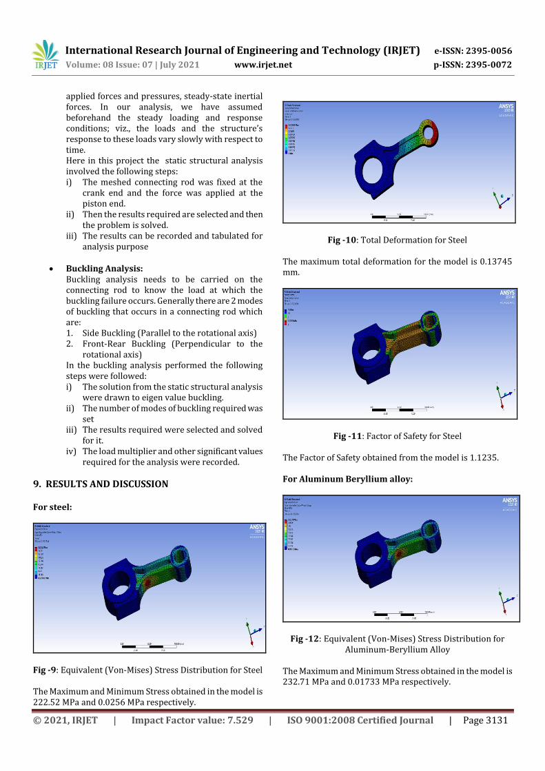
9. RESULTS AND DISCUSSION For steel:
Fig -9: Equivalent (Von-Mises) Stress Distribution for Steel The Maximum and Minimum Stress obtained in the model is 222.52 MPa and 0.0256 MPa respectively.
Fig -10: Total Deformation for Steel The maximum total deformation for the model is 0.13745 mm.
Fig -11: Factor of Safety for Steel The Factor of Safety obtained from the model is 1.1235. For Aluminum Beryllium alloy:
Fig -12: Equivalent (Von-Mises) Stress Distribution for Aluminum-Beryllium Alloy
The Maximum and Minimum Stress obtained in the model is 232.71 MPa and 0.01733 MPa respectively.
International Research Journal of Engineering and Technology (IRJET) e-ISSN: 2395-0056
Volume: 08 Issue: 07 | July 2021 www.irjet.net p-ISSN: 2395-0072
© 2021, IRJET | Impact Factor value: 7.529 | ISO 9001:2008 Certified Journal | Page 3132
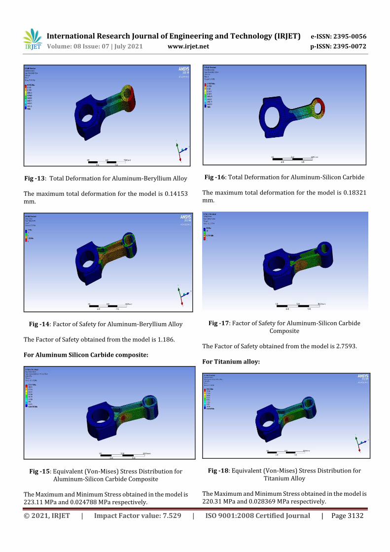
Fig -13: Total Deformation for Aluminum-Beryllium Alloy The maximum total deformation for the model is 0.14153 mm.
Fig -14: Factor of Safety for Aluminum-Beryllium Alloy The Factor of Safety obtained from the model is 1.186. For Aluminum Silicon Carbide composite:
Fig -15: Equivalent (Von-Mises) Stress Distribution for Aluminum-Silicon Carbide Composite
The Maximum and Minimum Stress obtained in the model is 223.11 MPa and 0.024788 MPa respectively.
Fig -16: Total Deformation for Aluminum-Silicon Carbide The maximum total deformation for the model is 0.18321 mm.
Fig -17: Factor of Safety for Aluminum-Silicon Carbide Composite
The Factor of Safety obtained from the model is 2.7593. For Titanium alloy:
Fig -18: Equivalent (Von-Mises) Stress Distribution for Titanium Alloy
The Maximum and Minimum Stress obtained in the model is 220.31 MPa and 0.028369 MPa respectively.
International Research Journal of Engineering and Technology (IRJET) e-ISSN: 2395-0056
Volume: 08 Issue: 07 | July 2021 www.irjet.net p-ISSN: 2395-0072
© 2021, IRJET | Impact Factor value: 7.529 | ISO 9001:2008 Certified Journal | Page 3133
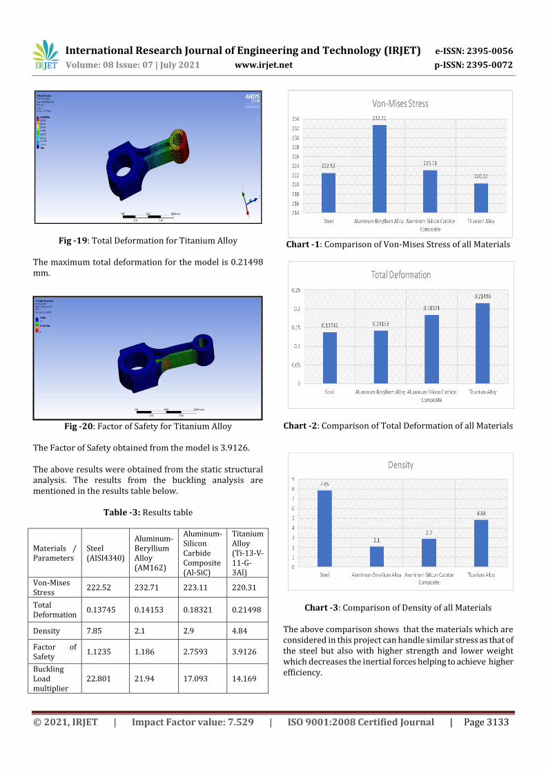
Fig -19: Total Deformation for Titanium Alloy
The maximum total deformation for the model is 0.21498 mm.
Fig -20: Factor of Safety for Titanium Alloy The Factor of Safety obtained from the model is 3.9126. The above results were obtained from the static structural analysis. The results from the buckling analysis are mentioned in the results table below.
Table -3: Results table
Materials / Parameters
Steel (AISI4340)
Aluminum-Beryllium Alloy (AM162)
Aluminum-Silicon Carbide Composite (Al-SiC)
Titanium Alloy (Ti-13-V-11-G-3Al)
Von-Mises Stress
222.52 232.71 223.11 220.31
Total Deformation
0.13745 0.14153 0.18321 0.21498
Density 7.85 2.1 2.9 4.84
Factor of Safety
1.1235 1.186 2.7593 3.9126
Buckling Load multiplier
22.801 21.94 17.093 14.169
Chart -1: Comparison of Von-Mises Stress of all Materials
Chart -2: Comparison of Total Deformation of all Materials
Chart -3: Comparison of Density of all Materials
The above comparison shows that the materials which are considered in this project can handle similar stress as that of the steel but also with higher strength and lower weight which decreases the inertial forces helping to achieve higher efficiency.
International Research Journal of Engineering and Technology (IRJET) e-ISSN: 2395-0056
Volume: 08 Issue: 07 | July 2021 www.irjet.net p-ISSN: 2395-0072
© 2021, IRJET | Impact Factor value: 7.529 | ISO 9001:2008 Certified Journal | Page 3134
10. CONCLUSIONS 1. Solid model of the connecting was created in CATIA V5 according to the design specification and analysis was performed under the effect of both tensile and compressive loads using ANSYS Workbench. 2. From the above work, we can observe that the minimum stresses among all loading conditions were found at the crank end and maximum stresses at the piston end. Hence the material can be reduced at the crank end, which reduces the material cost. Conducting dynamic analysis will help in further optimization of the connecting rod. 3. From the study carried out we can say that the connecting rod can be designed and optimized under a load range of both compression and tension for lighter materials with better performance and efficiency compared to steel. 4. From the analysis performed in the current work we can conclude that stresses of all the materials are almost comparable and also within the safe limit, i.e., well below the yield stress. 5. High bending stresses due to inertia forces can be prevented as the lighter materials used in the analysis have better section modulus compared to the section modulus of the material of the connecting rod in existence which is steel. 6. The inertia force is reduced by reducing the weight of the connecting rod and the results of the materials analysed are compared with the existing material which is carbon steel. It was also found that the equivalent stresses for all the materials were close to the same. 7. The static analysis shows us that the equivalent stress is maximum at the I-section near the bigger end of the connecting rod. 8. Connecting rod made of carbon steel has a lesser strength to weight ratio compared to the other materials under consideration. 9. Eigen value buckling analysis was carried out and it was observed that the buckling load which can be withstood by the connecting rod was approximately 22 times the applied load for Steel and Al-Be Alloy while 17 times for Al-SiC Composite and 14 times for Titanium Alloy.
11. FUTURE SCOPE 1. Dynamic analysis of the connecting rod can also be performed to get a better analysis. 2. Thermal analysis of the connecting rod can be performed to minimize the thermal stress effect on connecting rod. 3. Due to the presence of a small amount of torsional moment at the end points torsional analysis can be carried out. 4. To define the life of the connecting rod fatigue analysis can be carried out. 5. For minimizing the wear failure of the connecting rod work on internal coating to reduce wear can be done. 6. Modal analysis can be performed for minimizing
premature failure.
REFERENCES [1] A. Pandiyan, G. Arunkumar and G. Premkumar. 2019. “Design, Analysis and Topology Optimization of a Connecting Rod for Single Cylinder 4-Stroke Petrol Engine”, January 2020, International Journal of Vehicle Structures and Systems 11(4):439-442. [2] Shubham Tiwari, Ajay Kumar Kaviti – “Parameters influencing connecting rod: A Review”, International Journal of Scientific & Engineering Research, Volume 6, Issue 8, August-2015 8 ISSN 2229-5518 IJSER © 2015. [3] Vikas Singh, Sumit Kr. Verma, Harish Chandra Ray, Vishal Kr. Bharti, Abhinesh Bhaskar - “Design and Analysis of Connecting Rod for Different Material Using ANSYS Workbench 16.2.” International Journal of Engineering and Advanced Technology (IJEAT), ISSN: 2249 – 8958, Volume-9 Issue-3, February 2020. [4] Somnath Chattopadhyay - “SELECTION OF MATERIAL, SHAPE, AND MANUFACTURING PROCESS FOR A CONNECTING ROD”, AC 2010-926. [5] Adnan Ali Haider, Akash Kumar, Ajinkya Chowdhury, Moin Khan, P. Suresh - “Design and Structural Analysis of Connecting Rod”, International Research Journal of Engineering and Technology (IRJET), Vol. 5 Issue 5, May 2018, Pg. 282-285. [6] Kuldeep B, Arun L.R, Mohammed Faheem “ANALYSIS AND OPTIMIZATION OF CONNECTING ROD USING ALFASiC COMPOSITES”, ISSN: 2319- 875, International Journal of Innovative Research in Science, Engineering and Technology, Vol. 2, Issue 6, June 2013. [7] Ashby, M. F., Shercliff, H., and Cebon, D. (2008) – “Materials: Engineering, Science, Processing and Design”, Butterworth - Heinmann, Paperback ISBN: 9780081023761. [8] Mr. H D. Nitturkar, Mr. S M. Kalshetti, Mr. A R. Nadaf – “Design and Analysis of Connecting Rod using Different Materials”, Volume: 07 Issue: 03, Mar 2020. [9] Pravardhan S. Shenoy and Ali Fatemi - “Connecting Rod Optimization for Weight and Cost Reduction” 2005, SAE International, International Journal of Latest Trends in Engineering and Technology (IJLTET) Vol. 1 Issue 3 September 2012, ISSN: 2278-621X. [10] Mirehei, A., Zadeh, M.H., Jafari, A. and Omid, M. (2008) - “Fatigue analysis of Connecting Rod of universal tractor through finite element method (ANSYS)”, Journal of Agricultural Technology 4(1): 21-27. [11] “Design Data Handbook for Mechanical Engineers – Fourth Edition” by K. Mahadevan and K. Balaveera Reddy published by CBS Publishers & Distributors Pvt. Ltd.
Related Documents


