1 Design and Analysis of a Thermal Control System A thesis submitted to the department of Mechanical and Chemical Engineering (MCE), Islamic University of Technology (IUT), in the partial fulfillment of the requirement for the degree of Bachelor of Science in Mechanical Engineering. Prepared By Md. Nahidul Hasan (121423) Md. Shahriar Hasan Shaown (121455) Abdulahi Abdirahman Kassim (121439) Supervised By Prof. Dr. Nurul Absar Chowdhury Department of Mechanical and Chemical Engineering (MCE) Islamic University of Technology (IUT)

Welcome message from author
This document is posted to help you gain knowledge. Please leave a comment to let me know what you think about it! Share it to your friends and learn new things together.
Transcript

1
Design and Analysis of a Thermal Control System
A thesis submitted to the department of Mechanical and Chemical Engineering (MCE), Islamic University of Technology (IUT), in the partial fulfillment of the
requirement for the degree of Bachelor of Science in Mechanical Engineering.
Prepared By
Md. Nahidul Hasan (121423)
Md. Shahriar Hasan Shaown (121455)
Abdulahi Abdirahman Kassim (121439)
Supervised By
Prof. Dr. Nurul Absar Chowdhury
Department of Mechanical and Chemical Engineering (MCE) Islamic University of Technology (IUT)

2
Organization of Islamic Cooperation (OIC)
DECLARATION
This is to certify that the work presented in this thesis is an outcome of the
experiment and research carried out by the authors under the supervision of
Prof. Dr. Nurul Absar Chowdhury.
Signature Of The Candidates
____________________ ___________________
Md. Nahidul Hasan Md. Shahriar Hasan Shaown
(Author) (Author)
_____________________
Abdulahi Abdirahman Kassim
(Author)
Signature of Supervisor
_____________________
Prof. Dr. Nurul Absar Chowdhury
Professor Department of Mechanical and Chemical Engineering (MCE)
Islamic University of Technology (IUT) Board Bazar, Gazipur Dhaka, Bangladesh

3
ACKNOWLEDGEMENT
All praises to Almighty Allah (Sbw) who blessed us with potential and patience to complete this project successfully overcoming the obstacles in the way. It is not sufficient to only give thanks to some people who helped and guided us when needed and without them the thesis could never come into being successfully in time. Our gratitude and respect to our supervisor Prof. Dr. Nurul Absar Chowdhury, MCE Department, Islamic University of Technology(IUT) for his encouragement, erudite advices and extreme patience throughout the course for establishing such a creative project. Deepest gratitude to Mr. Md Abdul Motalib, Fabrication and welding shop, Department of Mechanical and Chemical Engineering (MCE), Islamic University of Technology (IUT) and Mr. Md.Abu Hossain, Thermodynamics and Thermo-fluid Lab Refrigeration and air-conditioning lab for their help throughout this work. We would also like to give thanks to all faculty members of the department for their advice and support throughout the project. All of us are indebted to our family members for their moral supports and prayers. Although we tried our best to complete this thesis flawlessly, we seek apology if there is any mistake found in this report.

4
ABSTRACT
The pressure vessel contains high pressurized fluid so that the selection of material and the design of the pressure vessel are most important. The pressure vessel contains high internal pressure. It must passes the sequence of hydrostatic test this test gives the capability of the construction to survive internal pressure. The analytical design of the pressure vessel is by using as per ASME code sec VIII division I. The dimension and stresses which works on pressure vessel can be found out by ASME code. These stresses are studying by using FEM and equate with theoretical value. We need to write code for the microprocessor .For writing code Arduino IDE was used. For controlling the coils and pump electro-mechanical relay was used.
5
Contents 1.1 INTRODUCTION: ...................................................................................................................................... 7
1.2 OBJECTIVE: .......................................................................................................................................... 9
CHAPTER 2 PROPOSED DESIGN ................................................................................................................ 10
2.1 Pressure vessel: ................................................................................................................................. 10
2.2 Cooling system: ................................................................................................................................. 10
2.3 Heating system: ................................................................................................................................ 10
2.4 Agitator: ............................................................................................................................................ 11
2.5 PROPOSED DESIGN ........................................................................................................................... 11
CHAPTER 3 DESIGN PROCEDURE .............................................................................................................. 13
3.1 PRESSURE VESSEL: ...................................................................................................................... 13
3.1.1 SHAPE OF A PRESSURE VESSEL: ....................................................................................... 13
3.1.2 Cylindrical Pressure Vessel ....................................................................................................... 14
3.1.3 USES OF PRESSURE VESSEL: .............................................................................................. 14
3.1.4 VESSEL HEAD: ............................................................................................................................. 14
3.1.5 VESSEL BODY: ...................................................................................................................... 18
3.2 GASKET : ........................................................................................................................................... 20
3.2.1 GASKET MATERIAL: ............................................................................................................... 20
HEATING SYSTEM: ........................................................................................................................ 23
3.4 Cooling System: ................................................................................................................................ 25
3.4.1 Water cooling: ............................................................................................................................ 25
Advantages .............................................................................................................................................. 25
3.5 Safety Measures: ............................................................................................................................... 26
3.6 DESIGN OF COOLING COIL: ....................................................................................................... 27
3.7 AGITATOR: ..................................................................................................................................... 31
IMPELLER TYPES ............................................................................................................................ 31
IMPELLER SIZE ................................................................................................................................ 31
IMPELLER SPEED ............................................................................................................................ 31
IMPELLER LOCATION .................................................................................................................... 32
IMPELLER SELECTION .................................................................................................................. 33
Separation of 2 immiscible liquids due to density variation. Such circumstances occur naturally: for
example, due to variations in temperature in the atmosphere or temperature and salinity variety. .... 34

6
3.8 SELECTION OF MOTOR: .............................................................................................................. 36
CHAPTER 4 CALCULATION ................................................................................ 38
4.1 Thickness of the vessel considering internal pressure: .................................................................... 38
4.2 Thickness of torispherical head : ..................................................................................................... 38
4.3 Thickness of the bottom dished head: ............................................................................................... 39
CHAPTER 5 ELECTRICAL CONTROL SYSTEM ...................................................................................... 41
5.1 CIRCUIT DIAGRAM: .......................................................................................................................... 42
5.2 Temperature Sensing: ....................................................................................................................... 43
5.3 COMPLETE SETUP: ...................................................................................................................... 44
CHAPTER 6 CONTROL LOGIC ................ 45
Arduino processor can perform certain command written by using arduino standard library. Here code is
written to control the coils and the pump. Codes are explained in a specific manner below: .................... 45
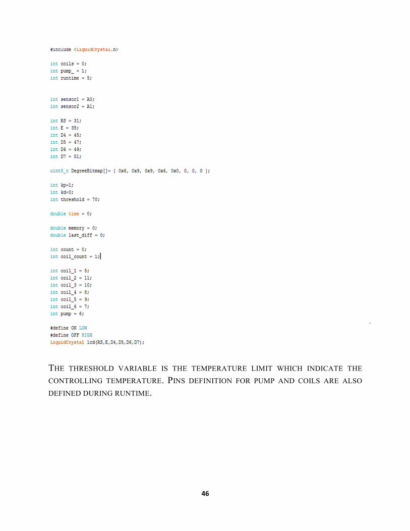
6.1 Initialization of variables: ................................................................................................................. 45
This section of the code is used to initialize of the variables which is necessary to run the program and
control the electric circuit .desired equipment to control in the circuit is the coils, pump and time .to do so,
.................................................................................................................................................................... 45
Three integer variables (coils, pump and runtime) are initialized............................................................... 45
Sensor 1 and sensor 2 variables are used to receive and send the sensor data to arduino pins which are
defined as a1 and a2. ................................................................................................................................... 45
Coils 1 to 6 are assigned their respective pins through variable assignment. ............................................. 45
Required pin for pump is also assigned during runtime. ............................................................................ 45
6.2 SETUP FUNCTION:............................................................................................................................. 47
6.3 CONTROL LOOP: ........................................................................................................................... 48
6.4 Temperature reading: ........................................................................................................................ 52
CHAPTER 7 EXPERIMENT ............................. 54
7.2 Experiment with 6 coils: ................................................................................................................... 55
7.3 Experiment with 4 coils: ................................................................................................................... 56
7.4 Experiment with 2 coils : .................................................................................................................. 57
CHAPTER 8 CONCLUSION AND RECOMMENDATIONS .............. 58
8.2 Recommendation: ............................................................................................................................. 58
Reference .................................................................................................................................................... 59

7
CHAPTER 1
1.1 INTRODUCTION:
Pressure vessel is reservoirs which have high pressurized fluid inside it. The
pressure is variance between inside and outside of the container. The inside
pressure is normally greater than the outside pressure .The fluid inside the vessel
may undergoes change in state as in case of steam boiler ,or may combine with
other substances as in the reservoir. The size and geometry from of pressure vessel
are differs as per application. The large cylinder-shaped vessel used for high –
pressure gas loading to the minor size used as hydraulic components for air craft
With increasing demands from industrial processes for higher operating pressures
and higher temperature, new machineries have been industrialized to grip the
present day specialized necessities. Multilayer Pressure Vessels have extended the
art of pressure vessel structure and presented the process designer with a
dependable portion of equipment useful in a wide range of operating circumstances
for the problems generated by the storage of hydrogen and hydrogenation
processes the term pressure vessel signified to those reservoirs or containers, which
are subjected to internal or external pressures. The pressure vessels are used to
store fluids under pressure.
The fluid being stored may undergo a change of state inside the pressure vessels as
in case of steam boilers or it may combine with other reagents as in chemical
plants. Pressure vessels find wide applications in thermal and nuclear power plants,
process and chemical industries, in space and ocean depths, and in water, steam,
gas and air supply system in industries. Solid wall pressure vessels consist of a
single cylindrical shell with close end. Due to high internal pressure and large
thickness the shell is considered as thick cylinder. For thick cylinder wall thickness
must exceed one-tenth(1/10) of the inside diameter .A solid wall vessel is also
8
termed as mono block in pressure vessel .The application of pressure vessel in very
wide in thermal and nuclear power plant process and chemical industries in space
and depth and in water, steam, gas, and air supply system in industries . The
material of a pressure vessel may be brittle such as cast iron or ductile such as mild
steel. So these are construction of high pressure-vessels. A solid wall vessel
produced by forging or drilling a solid rod of metal .the cylinder formed by
bending a sheet of metal with longitude weld and shrink fit construction in which
vessel is built up of two or more concentric shells each shell progressively shrunk
on from inside outward from economic and fabrication considerations the number
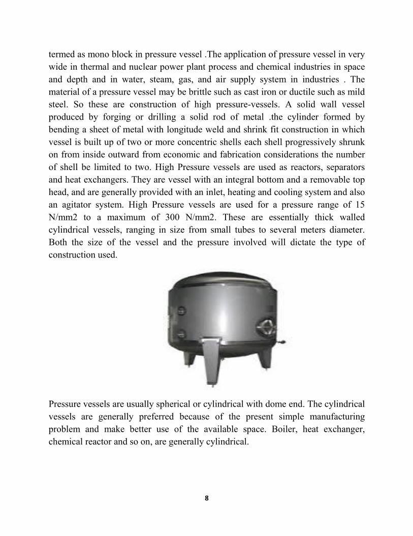
of shell be limited to two. High Pressure vessels are used as reactors, separators
and heat exchangers. They are vessel with an integral bottom and a removable top
head, and are generally provided with an inlet, heating and cooling system and also
an agitator system. High Pressure vessels are used for a pressure range of 15
N/mm2 to a maximum of 300 N/mm2. These are essentially thick walled
cylindrical vessels, ranging in size from small tubes to several meters diameter.
Both the size of the vessel and the pressure involved will dictate the type of
construction used.
Pressure vessels are usually spherical or cylindrical with dome end. The cylindrical
vessels are generally preferred because of the present simple manufacturing
problem and make better use of the available space. Boiler, heat exchanger,
chemical reactor and so on, are generally cylindrical.

9
1.2 OBJECTIVE:
1. To design a pressure vessel to contain water and to heat it with the help of a
heating system.
2. To design a cooling system to cool down the hot water if temperature
exceeds desirable limit.
3. To design a water circulation system for the cooling process with the help of
a pump.
4. To design a micro-controller based control system to manipulate the heating
system and water cooling operation based on requirements.
5. Combining altogether to create an automated thermal control system.
In the project designing there are different parts.
They are-
a) Design of Vessel
b) Design of heating system
c) Design of cooling system
d) Agitator design
e) Selection of motor
f) Microcontroller design
10
CHAPTER 2
PROPOSED DESIGN
2.1 Pressure vessel:
1) Vessel head
2) Vessel body
3) Gasket
2.2 Cooling system:
1) Cooling coil made by copper tube
2) Pump to circulate cold water
2.3 Heating system:
Heating elements (nichrome coil) to heat up the vessel for heating element we
considered to use nichrome for its better thermal conductivity and lower thermal
expansion. It will be joined with the pressure vessel using bolt joint. So that it will
be adjustable and can be replaced anytime when necessary. For the housing of
heating elements a custom heater was made especially to accommodate 8 heating
coils which will be placed around the vessel by keeping a considerable distance
between each two coils. For proper heating coils of 1500 watts are used and to
make it down to 500 watts three coils are joined in series. Coils will be supplied
with a 220 V ac current. Number of active coils can be controlled by micro-
controller.

11
2.4 Agitator:
Agitation is a means whereby mixing of phases can be accomplished and by which
mass and heat transfer can be enhanced between phases or with external surfaces.
In its most general sense, the process of mixing is concerned with all combinations
of phases of which the most frequently occurring ones are
1. Gases with gases.
2. Gases into liquids: dispersion.
3. Gases with granular solids: fluidization, pneumatic
4. Liquids into gases: spraying and atomization.
5. Liquids with liquids: dissolution, emulsification, dispersion
6. Liquids with granular solids: suspension.
7. Pastes with each other and with solids
. 8. Solids with solids: mixing of powders
2.5 PROPOSED DESIGN

12

13
CHAPTER 3
DESIGN PROCEDURE
3.1 PRESSURE VESSEL:
For our project we will use a pressure vessel made of stainless steel. As we are
using water as our working fluid and also we are working under high temperature
there can be corrosion if we use any materials other than stainless steel.
We may use stainless steel coating over a vessel made of mild steel but it will lead
to leakage and accurate value cannot be determined. In the upper portion of the
vessel, we have to customize it to add a agitator and water flow pipe. With the flow
pipe we fill up the vessel with water and agitator helps us to maintain the mixing of
heat to water properly.
According to the ASME Boiler and Pressure Vessel Code (BPVC), Code Section VIII, pressure vessels are containers for the containment of pressure, either internal or external. This pressure may be obtained from an external source or by the application of heat from a direct or indirect source as a result of a process, or any combination thereof.
The ASME Code is the construction code for pressure vessels and contains mandatory requirements, specific prohibitions, and non-mandatory guidance for pressure vessel materials, design, fabrication, examination, inspection, testing and certification.
3.1.1 SHAPE OF A PRESSURE VESSEL:
Pressure vessels can theoretically be almost any shape, but shapes made of sections of spheres, cylinders, and cones are usually employed. A common design is a cylinder with end caps called heads. Head shapes are frequently either hemispherical or dished (torispherical). More complicated shapes have historically been much harder to analyze for safe operation and are usually far more difficult to construct.
Theoretically, a sphere would be the best shape of a pressure vessel. Unhappily, a spherical shape is tough to manufacture, therefore more expensive, so most pressure vessels are cylindrical with 2:1 semi-elliptical heads or end caps on each
14
end. Smaller pressure vessels are assembled from a pipe and two covers. A disadvantage of these vessels is that greater breadths are more expensive.
3.1.2 Cylindrical Pressure Vessel
Cylinders are widely used for storage due to their being less expensive to produce than spheres. However, cylinders are not as strong as spheres due to the weak point at each end.
This weakness is reduced by hemispherical or rounded ends being fitted. If the whole cylinder is manufactured from thicker material than a comparable spherical vessel of similar capacity, storage pressure can be similar to that of a sphere.
3.1.3 USES OF PRESSURE VESSEL:
Pressure vessels are used in a variety of applications in both industry and the private sector. They appear in these sectors as industrial compressed air receivers and domestic hot water storage tanks. Other examples of pressure vessels are diving cylinders, recompression chambers, distillation towers, autoclaves, and many other vessels in mining operations, oil refineries and petrochemical plants, nuclear reactor vessels, submarine and space ship habitats, pneumatic reservoirs, hydraulic reservoirs under pressure, rail vehicle airbrake reservoirs, road vehicle airbrake reservoirs, and storage vessels for liquified gases such as ammonia, chlorine, propane, butane and LPG.
3.1.4 VESSEL HEAD:
A head is one of the end caps on a cylindrically shaped pressure vessel .vessel head
is round headed and 12 inch in diameter made of stainless steel. It is designed in
solid works according to calculated measurement.
Types of head:
1) Ellipsoidal Head
2) Hemispherical Head
3) Torispherical Head
These three types of ASME Pressure Vessel Dished Heads:

15
Ellipsoidal head
This is also called a 2:1 elliptical head. The shape of this head is more economical, because the height of the head is just a quarter of the diameter. Its radius varies between the major and minor axis.
Hemispherical head A sphere is the ideal shape for a head, because the pressure in the vessel is divided equally across the surface of the head. The radius (R) of the head equals the radius of the cylindrical part of the vessel.
Torispherical Head These heads have a dish with a fixed radius (CR), the size of which depends on the
type of torispherical head. The transition between the cylinder and the dish is called the knuckle. The knuckle has a toroidal shape.
Vessel for the experiment is torispherical. Design and modeling is done by solid works.
Dimension: 12 inch
Material: Stainless steel(SS)

16
This is a torispherical head. The dish has a radius that equals the diameter of the cylinder it is attached to. The knuckle has a radius that equals a tenth of the diameter of the cylinder

17
REAL VESSEL HEAD:
These heads have a dish with a fixed radius (CR), the size of which depends on the type of torispherical head. The transition between the cylinder and the dish is called the knuckle. The knuckle has a toroidal shape.
This is a torispherical head. The dish has a radius that equals the diameter of the cylinder it is attached to. The knuckle has a radius that equals a tenth of the diameter of the cylinder.

18
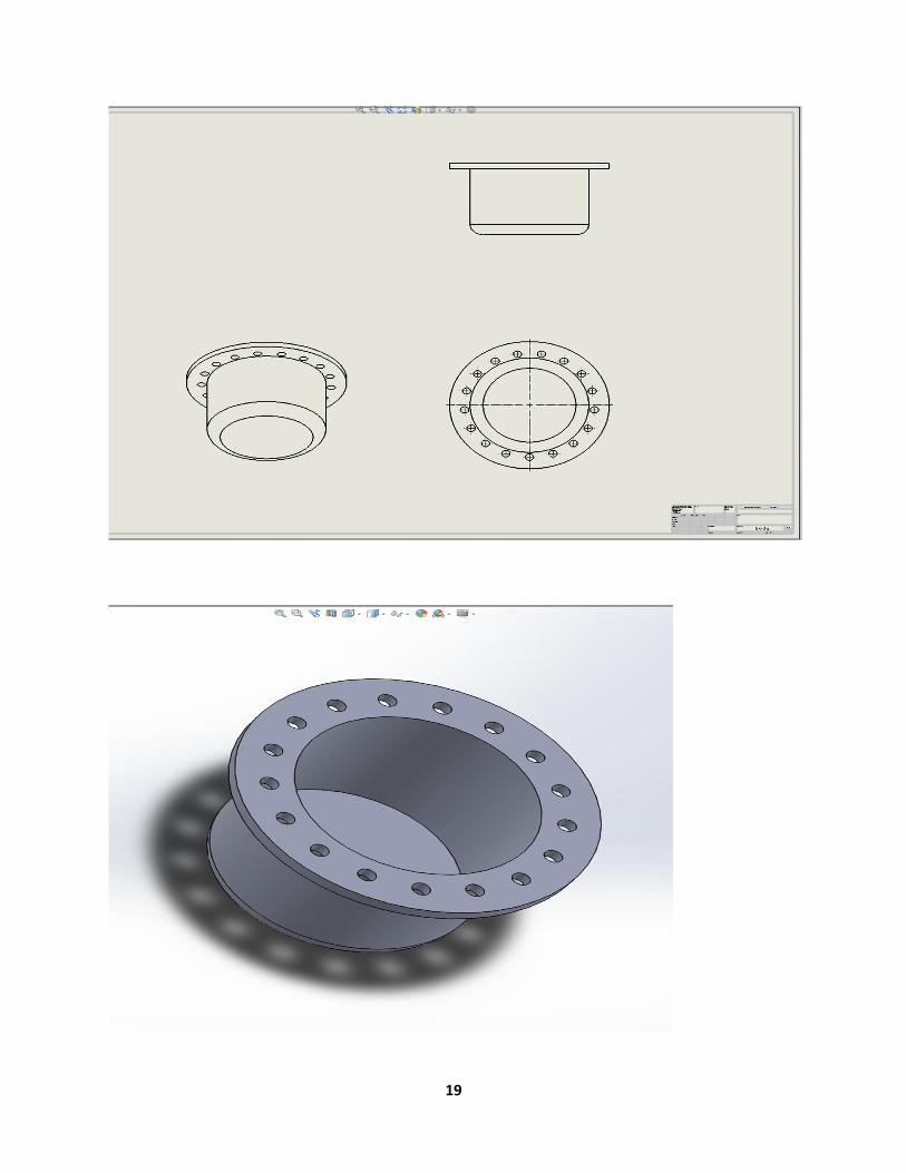
3.1.5 VESSEL BODY:
Vessel body is 12 inch in diameter and about 500mm long made out of stainless
steel. Design of vessel body was made with the help of solid works.
19
20
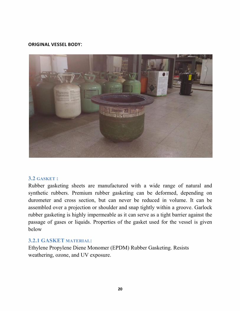
ORIGINAL VESSEL BODY:
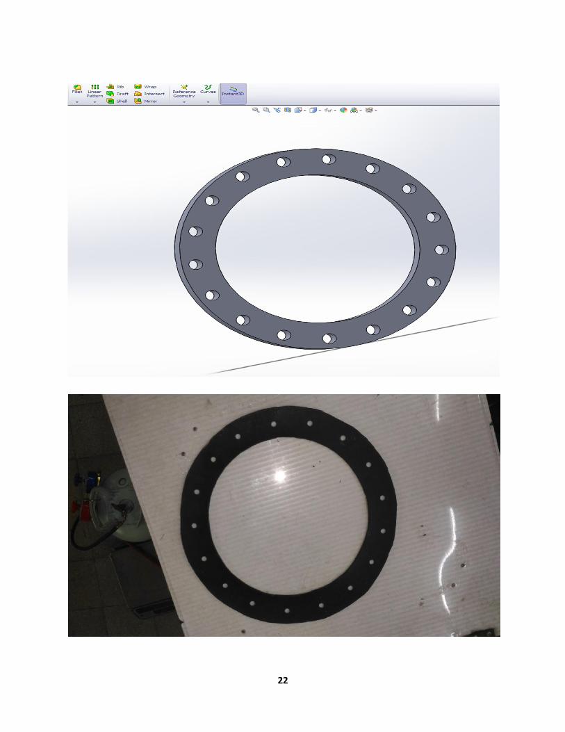
3.2 GASKET :
Rubber gasketing sheets are manufactured with a wide range of natural and
synthetic rubbers. Premium rubber gasketing can be deformed, depending on
durometer and cross section, but can never be reduced in volume. It can be
assembled over a projection or shoulder and snap tightly within a groove. Garlock
rubber gasketing is highly impermeable as it can serve as a tight barrier against the
passage of gases or liquids. Properties of the gasket used for the vessel is given
below
3.2.1 GASKET MATERIAL:
Ethylene Propylene Diene Monomer (EPDM) Rubber Gasketing. Resists
weathering, ozone, and UV exposure.
21
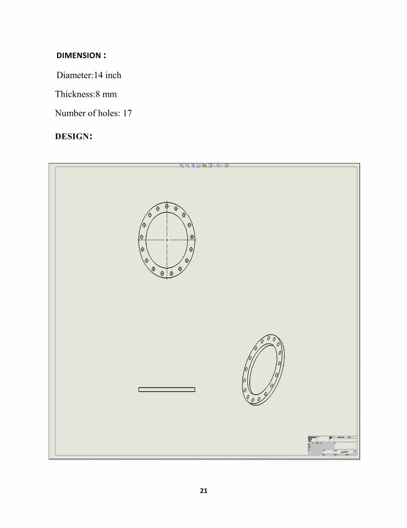
DIMENSION :
Diameter:14 inch
Thickness:8 mm
Number of holes: 17
DESIGN:
22

23
HEATING SYSTEM:
HEATING ELEMENT:
For heating element we considered to use nichrome for its better thermal
conductivity and lower thermal expansion. it will be joined with the pressure vessel
using bolt joint. So that it will be adjustable and can be replaced anytime when
necessary. For the housing of heating elements a custom heater was made
especially to accommodate 8 heating coils which will be placed around the vessel
by keeping a considerable distance between each two coils. For proper heating
coils of 1500 watts are used and to make it down to 500 watts three coils are joined
in series. Coils will be supplied with a 220 V ac current. Number of active coils
can be controlled by micro-controller.
24
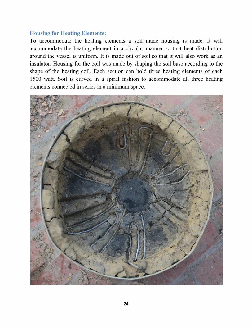
Housing for Heating Elements:
To accommodate the heating elements a soil made housing is made. It will
accommodate the heating element in a circular manner so that heat distribution
around the vessel is uniform. It is made out of soil so that it will also work as an
insulator. Housing for the coil was made by shaping the soil base according to the
shape of the heating coil. Each section can hold three heating elements of each
1500 watt. Soil is curved in a spiral fashion to accommodate all three heating
elements connected in series in a minimum space.

25
3.4 Cooling System:
Cooling system is used to cool the water. Copper pipe is used here. A coil of
copper pipe having .5 inch diameter is used here. It has two outcome. One is water
input and the other is for water output. Input water is given from outside by which
heated water is cooled and the output water would take the heat and flow outside.
Copper is used because it has high heat conductive and it is not corrosive too. One
of the areas that I think needs improvement in water cooling is the transport of the
liquid coolant from point A to point B. The current method of choice is by using a
soft hose such as silicon or vinyl. These hoses have the advantage of being easy to
use and fairly reliable. They also have their disadvantages. For example, have you
ever tried to do a sharp bend in your hosing? The first thing you probably noticed
is it kinked which could potentially lead to a coolant blockage. To prevent kinking,
some of you have gone to a thicker outer wall in the hose. This helps a little, but
now the hose is bulky, and very stiff.
3.4.1 Water cooling:
Water cooling is a method of heat removal from components and industrial
equipment. As opposed air cooling, water is used as the heat conductor. Water
cooling is commonly used for cooling automobile and inter combustion engines
and large industrial facilities such as power plants, hydraulic generator, petroleum
refineries and chemical plants. Other uses include cooling the barrels of machine
guns, cooling of lubricant oil in pumps; for cooling purposes in heat exchangers;
cooling products from tanks or columns, and recently, cooling of various major
components inside high-end personal computers. The main mechanism for water
cooling is convective heat transfer.
Advantages
Water is inexpensive and non-toxic. The advantages of using water cooling over air cooling include water's higher specific heat capacity, density, and thermal conductivity. This allows water to transmit heat over greater distances with much less volumetric flow and reduced temperature difference.
26
For cooling CPU cores in computing equipment, the primary advantage of water cooling is that it is tremendously increased ability to transport heat away from source to a secondary cooling surface allows for large, more optimally designed radiators rather than small, inefficient fins mounted directly on the heat source.
The water jacket around an engine is also very effective at deadening mechanical noises, which makes the engine quieter. However, the primary disadvantage is that it costs significantly more than an air-cooled engine system.
3.5 Safety Measures:
Liquid cooling techniques are increasingly being used for the thermal management of electronic components. This type of cooling is a solution to ensure the optimization of energy efficiency while simultaneously minimizing noise and space requirements. Especially it is useful in supercomputers or Data Centers as maintenance of the racks is quick and easy. After disassembly of the rack, advanced technology of quick release couplings eliminate spillage for the safety of operators and protects the integrity of fluids (no impurities in the circuits). These couplings are also capable of being locked (Panel mounted?) to allow blind connection in difficult to access areas. It is important in electronics technology to analyze the connection systems to ensure:
Non-spill sealing (clean break, flush face couplings) Compact and lightweight (materials in special aluminum alloys) Operator safety (disconnection without spillage) Quick-release couplings sized for optimized flow Connection guiding system and compensation of misalignment during
connection on rack systems Excellent resistance to vibration and corrosion Designed to withstand a large number of connections even on refrigerant
circuits under residual pressure
27
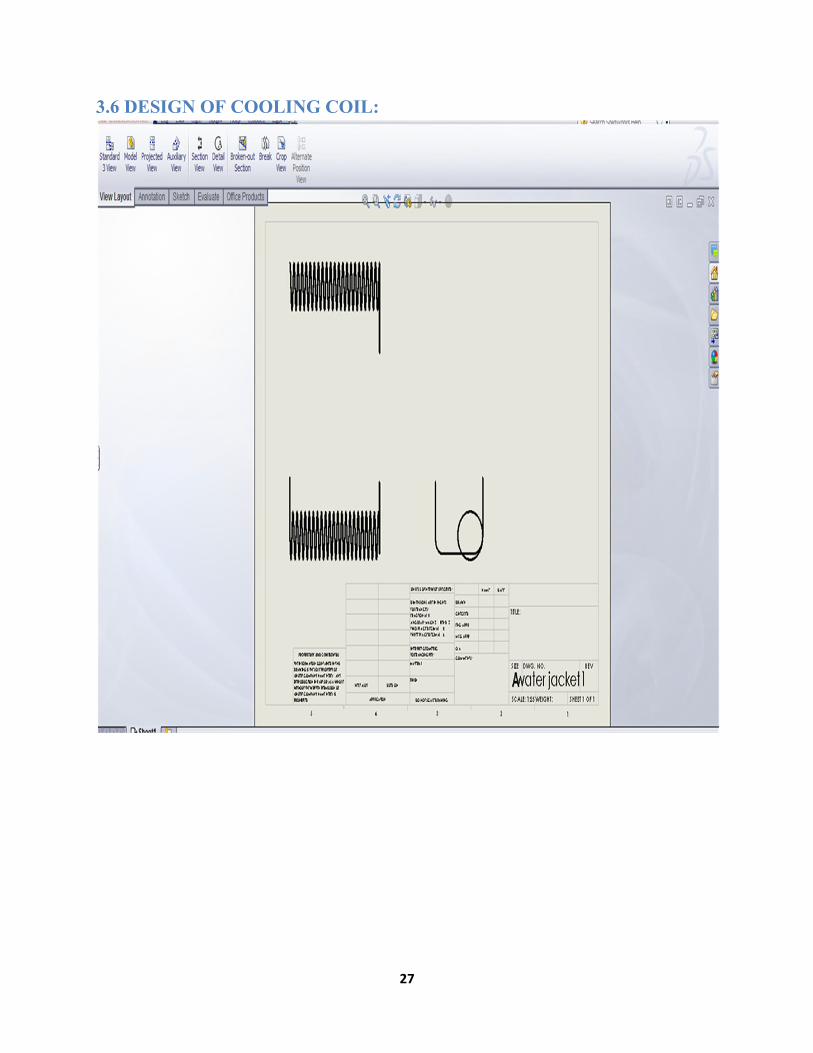
3.6 DESIGN OF COOLING COIL:
28
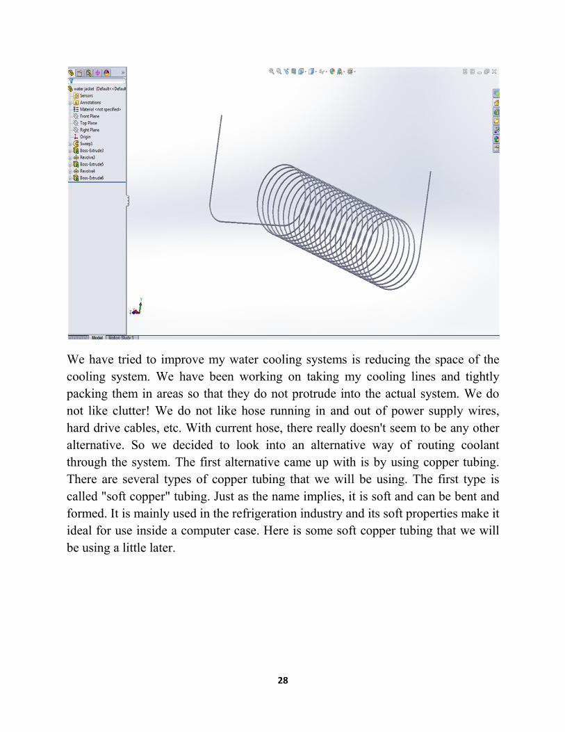
We have tried to improve my water cooling systems is reducing the space of the
cooling system. We have been working on taking my cooling lines and tightly
packing them in areas so that they do not protrude into the actual system. We do
not like clutter! We do not like hose running in and out of power supply wires,
hard drive cables, etc. With current hose, there really doesn't seem to be any other
alternative. So we decided to look into an alternative way of routing coolant
through the system. The first alternative came up with is by using copper tubing.
There are several types of copper tubing that we will be using. The first type is
called "soft copper" tubing. Just as the name implies, it is soft and can be bent and
formed. It is mainly used in the refrigeration industry and its soft properties make it
ideal for use inside a computer case. Here is some soft copper tubing that we will
be using a little later.
29
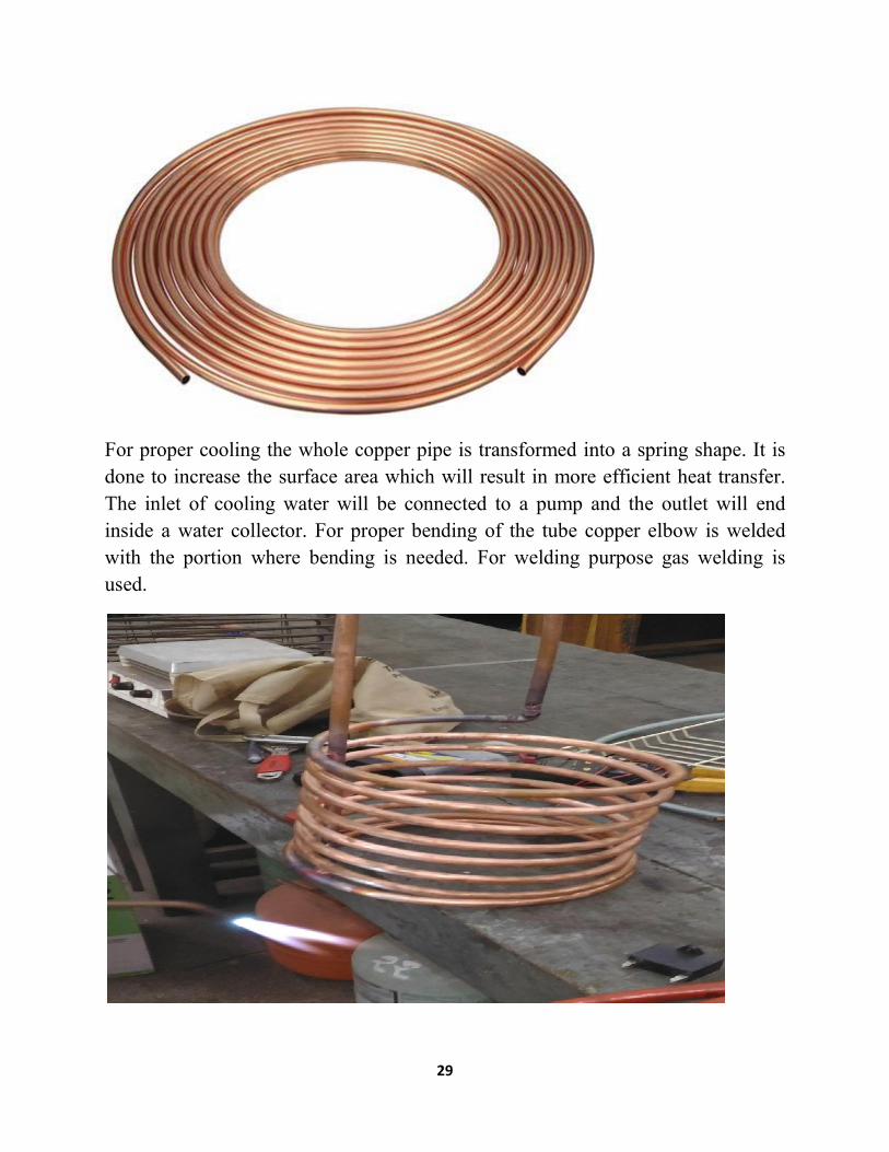
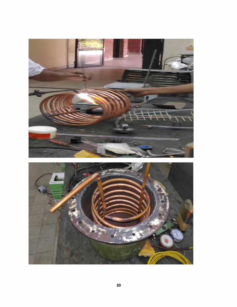
For proper cooling the whole copper pipe is transformed into a spring shape. It is
done to increase the surface area which will result in more efficient heat transfer.
The inlet of cooling water will be connected to a pump and the outlet will end
inside a water collector. For proper bending of the tube copper elbow is welded
with the portion where bending is needed. For welding purpose gas welding is
used.
30
31
3.7 AGITATOR:
Industrial agitators are machines used in industries that process products in the chemical, food, pharmaceutical and cosmetic industries, in a view of :
mixing liquids together promote the reactions of chemical substances keeping homogeneous liquid bulk during storage
increase heat transfer (heating or cooling)
IMPELLER TYPES
A basic classification is into those that circulate the liquid axially and those that
achieve primarily radial circulation. Some of the many shapes that are being used
will be described shortly.
IMPELLER SIZE
This depends on the kind of impeller and operating conditions described by the
Reynolds, Froude, and Power numbers as well as individual characteristics whose
effects have been correlated. For the popular turbine impeller, the ratio of
diameters of impeller and vessel falls in the range, d/D,=0.3-0.6, the lower values
at high rpm, in gas dispersion, for example.
IMPELLER SPEED
With commercially available motors and speed reducers, standard speeds are 37,
45, 56, 68, 84, 100, 125, 155, 190, and 320rpm. Power requirements usually are
not great enough to justify the use of continuously adjustable steam turbine drives.
Two-speed drives may be required when starting torques are high, as with a settled
sluny.
32
IMPELLER LOCATION
Expert opinions differ somewhat on this factor. As a first approximation, the impeller can be placed at 1/6 the liquid level off the bottom. In some cases there is provision for changing the position of the impeller on the shaft. For off-bottom suspension of solids, an impeller location of 1/3 the impeller diameter off the bottom may be satisfactory. Criteria developed by Dickey (1984) are based on the viscosity of the liquid and the ratio of the liquid depth to the tank diameter, h/Q. Whether one or two impellers are needed and their distances above the bottom of the tank are identified in this table:
Maximum Impeller Clearance [cP (Pa sec)] h/Dt Impellers Lower Upper Viscosity level Number of
- <25,000 (<25) 1.4 1 hi3 (2/3)h <25,000 (<25) 2.1 2 Q/3 >25,000 (>25) 0.8 1 hI3 >25,000 (>25) 1.6 2 Dt 13 (2/3)h
Another rule is that a second impeller is needed when the liquid must travel more than 4 ft before deflection.
Type of Agitators and their functions:
Marine Propeller is generally an item produced by casting process in a foundry and it has 3 or 4 blades. Cast agitators have two basic advantages, uniformity of material and hard surface. These have tapering blades, and angle of blade varies from root to tip. This produces maximum axial flow. The diameter of Marine Propeller impeller is 15% to 30% of diameter of tank. These have tip speeds between 300 to 500 meters per minute.
Axial Flow Turbine, Turbo Propeller and Flat Blade Turbine have blades ranging from 3 to 6. These have tip speeds between 200 to 300 meters per minute. The diameter of impeller is 25% to 60% of tank diameter. For Axial Flow Turbine and Turbo Propeller, the angle of blade varies from 30 degrees (for less viscous liquids) to 60 degrees (for more viscous liquids). Standard angle is 45 degrees. Power requirement increases with higher pitch angle. For Flat Blade Turbine, the length of blade is 25% of diameter, and disk diameter is 60% to 70% of the diameter of impeller.
33
Paddle, Anchor, Anchor/Paddle or Gate have only 2 blades. These extend close to the tank wall and have tip speeds between 80 to 150 meters per minute. These push and rotate the liquid in a laminar flow. There is no axial or radial mixing. The width of blade is 1/8th or 1/10th of the agitator diameter.
IMPELLER SELECTION
As you can see, the first step to meeting your mixing objective is to identify your desired flow pattern, which is dictated by the impeller. Next, you must consider the 4 main factors for configuring your mixer. From there, you must address the mechanical requirements of your mixing process: pumping or flow. The mechanical requirements to produce flow or torque per unit volume, the most important relationship in mixing, are explained next.
Shear Stress
Parallel-acting force where 2 layers inside the fluid slide against each other. This is in contrast to compression (perpendicular-acting force), tension (stretching force), and torsion (twisting force).
Viscosity
Internal fluid resistance thought of as the “thickness” or “resistance to flow” of the liquid (i.e. water has viscosity of 1 centipoise vs honey, which is around 3,000 centipoise).
Power Number (NP)
Constant used to calculate power draw, unique to each type of mixing impeller.
34
Pumping Number (NQ)
Constant used to calculate flow or pumping rate, derived empirically for each unique shape of impeller.
Superficial Velocity
Velocity of the fluid being pumped downward by the impeller.
Annular Velocity
Rate at which the liquid is traveling upwards inside a tank past the impeller.
Solid Suspension
State of a solid when its particles are mixed with, but don’t dissolve in the fluid and are capable of separation (i.e. sand in water).
Stratification
Separation of 2 immiscible liquids due to density variation. Such circumstances occur naturally: for example, due to variations in temperature in the atmosphere or temperature and salinity variety.
Calculation of impeller diameter
1. For Marine Propeller, Axial flow turbine, and Turbo Propeller, based on the Type of Impeller, Agitator speed and Reynold's number selected, program will calculate the diameter of the impeller. Program reitirates till the width factor of impeller diameter to vessel diameter, is achieved by increasing or decreasing the agitator speed. It will indicate the calculated agitator speed and diameter of impeller. You can round it up to nearest value.
o Output Speeds of 1500 rpm Motor with Gearbox are: 300, 200, 150, 120, 100, 75, 60, 50, 43, 37, 30, 25, 22.
o Output Speeds of 1000 rpm Motor with Gearbox are: 200, 133, 100, 80, 67, 50, 40, 33, 29, 25, 20, 17, 14.
o Output Speeds of 750 rpm Motor with Gearbox are: 150, 100, 75, 60, 50, 38, 30, 25, 21, 19, 15, 13, 11.
o Output Speeds of Direct coupled Motor are: 1500, 1000, 750. o For any other speeds use Motor + V Belt Drive.

35
It then calculates pumping rate. Pumping rate = (pumpfac * (shaft rpm / 60.0) * impeller od3) in cu mm / sec. It then calculates Mixing time = Vessel Volume / Pumping Rate. Program indicates the value of mixing time. You can choose mixing time as per your requirements. Program will recalculate the diameter of the impeller and shaft rpm. You can choose these per your requirements. Program asks for number of impellers on shaft. If these are more than one, program will recalculate the diameter of the impeller. You can choose it per your requirements.
2. For Disc Blade turbine, Flat Blade turbine and Backward Blade turbine: Diameter of impeller depends on Width factor to Vessel Diameter. Program calculates Impeller OD and indicates it. Tip speed of impeller = 175 meters per minute, or 500 feet per minute. Agitator Speed depends on tip speed of impeller. It calculates RPM of agitator.
3. For Paddle, Anchor, Anchor/Paddle and Gate: Diameter of impeller depends on Width factor to Vessel Diameter. It calculates Impeller OD. Tip speed of impeller = 82.5 meters per minute or 250 feet per minute. Agitator Speed depends on tip speed of impeller. It calculates RPM of agitator.
Program then calculates the power absorbed for mixing. Absorbed Power in HP = (specific gravity * 1000 * number of impellers * power number * (shaft rpm / 60.0)3 (impod / 1000.0)5 * 1.1 * 1.2) / (9.81 * 75.0)
If the shaft RPM is less than 300, based on the absorbed power (output power of gearbox) and output RPM of gearbox, it selects gearbox. It indicates selected size of gearbox, which can be changed to next higher or lower value.
It then calculates diameter of shaft. You can select 4 types of materials for shaft.
Indicated values of Yield Stress and Elastic Limit, in Kgs/ mm2 are as follows.
Carbon Steel: Shear Stress 30.0, Elastic Limit 170.0.
EN8: Shear Stress 55.0 Elastic Limit 246.0
EN24: Shear Stress 80.0 Elastic Limit 320.0
Stainless Steel: Shear Stress 50.0 Elastic Limit 230.0
You can select Safety Factor for calculation of shaft diameter. Torque at end of
shaft = (746 * motor hp) / (2 * pi * (rpm / 60)) [in N-mt]
Bending Moment = Torque * Safety Factor [in N-mm]

36
3.8 SELECTION OF MOTOR:
What motor rating is used is determined by the amount of torque required to move
the load. Horsepower does not move the load, torque moves the load. A 1-hp, 6-
pole motor will develop 50% more torque than a 1-hp, 4-pole motor If the
manufacturer of the agitator is provided with the density of the material beforehand
they should determine what torque is required and supply a motor to suit.
If the original motor is going to be used it may be necessary to shave some
material off of the agitator blade.
Check with the motor manufacturer if the motors are thermally suitable for a
continuous (or X seconds) overload of 115% to 120% and then set the over current
protection relay to, say, 120 or even 125% FLC (preferably with the time delay of
X seconds) to account for sudden overload common in agitators. This should avoid
nuisance trips as long as the motor thermal capacity is sufficient since the
breakdown torque must be at least 150%FLT.
In our opinion, the agitator manufacturer should have guidelines for establishing
the driver size (and maybe gearbox too) for different materials. Especially
recognizing different densities or other liquid properties (i.e.: lumps, clumps,
solids,etc)
Motors are designed to have optimum continuous performance somewhere
between 80 and 100% load. Not all are the same. Some peak early, some peak at
full load, some are nearly flat. But all of them decline in efficiency after full load.
Higher output is possible, but at a higher watt/kW basis (and a higher winding
temp).
Many severe duty users will preclude the use of a motor in the Service Factor
range. And at least for MV and HV motors, IEC does not allow for anything other
than 1.0 SF. We know of several MV users who will require F insulation, B temp

37
rise @ 1.15 and still demand that the motor be sized to run at 90% of the name
plated Hp. Why? Because they know their operators will run up the load years
later, no matter what the original design parameters were.
"We build 'em, and operations tears 'em down"
All this to say that a properly sized motor running at or below 1.0 SF should have
lower amperage than one operating above rated load, the relay will need to be
changed.
Rewinding to a higher insulation level is only a band-aid. If the original space and
mounting could only accommodate the specific motor frame, then there would be
no choice. Otherwise, I would go with installing the right motor the first time.
There are more considerations in motor design than just the stator temperature.
Rotor cage and bearing temperatures are also impacted.

38
CHAPTER 4
CALCULATION
There are some calculation are needed for determining the thickness of pressure
vessel. There are three part of thickness in it.
Here we are calculating to design a jacketed vessel to hold 0.1m3 of water after
allowing 1/8th of volume as free space at 1200kpa and 1000c .
We get the following dimensions for the vessel:
4.1 Thickness of the vessel considering internal pressure:
t= {PDi /(2fj-P)+c}
where,
P=internal pressure=1320X103 N/m2
Di=0.49 m
f=allowable stress=112.8X10^6 N/m^2
J=welding joint efficiency=0.85
c=corrosion allowance=2mm
from the above values we get the thickness ,t=5.396mm
Considering external pressure :
pc={2E*(t/D0)3}/(1-poision ration)
Here ,
D0=0.5,
Pc=605X10^3 N/m^2 critical pressure which is taken as the design.
From here we find, t=5.18mm
4.2 Thickness of torispherical head :
Torispherical Head
These heads have a dish with a fixed radius (CR), the size of which depends on the

39
type of torispherical head. The transition between the cylinder and the dish is
called the knuckle. The knuckle has a toroidal shape.
This calculator determines the thickness of a Ellipsoidal Head Under Internal
Pressure with an internal pressure applied: Typical applications are propane tanks,
compressed air storage tanks etc.
t=(P Rc w/2fG)+c
Where w=1/4(3+( Rc/R1))0.5
Rc=Di=0.49 m
R1=6% Rc
Here we get t=7.58X10⁻³ m=7.58mm
4.3 Thickness of the bottom dished head:
t=(P Rc w/2fJ)+c;
40
Here we get t=8mm
Considering the external pressure:
T=4.4Rc [3(1-σ2)]0.25 X √(P/2E)+c
From here we get t=5.49 mm
Considering the highest among two thickness =8mm
Design of jacket :
jacket thickness ,t =[(P di )/(2fJ-P)]+c
Here ,
P=605X103 N/M2
Di = 0.49+2*0.05=0.59
f=112.8X10⁶
j=0.85
c=2mm
From here we get, t=2mm
41
CHAPTER 5
ELECTRICAL CONTROL SYSTEM
This is an Arduino project .It will help to control the heating elements automatically .The basic elements of thermal control system are:
Temperature sensor – LM35 is used, a cheap single package device. Relay or RC plug switches Screw terminals Box to trap the heat Heating element or incandescent bulb and fixture (or both)
The last item has been left deliberately vague. If you have an incandescent bulb (the kind that gets hot, not an energy-saving bulb), or a hot lamp for sporting injuries and such, it’s probably the easiest to set up. I’m using a heating band – basically a band of rubber that gets warm when electricity is passed through, used on carboys and kegs for initial fermentation stages in wine or beer making – technically, this can be a fire risk when not wound around something. You can also buy heating pads for the same purpose.
For safety reasons, I’m using these RC plugs to switch AC devices, with a controller hacked apart detailed in this home automation article. It’s wireless, so at no point need I actually touch live wires.
42
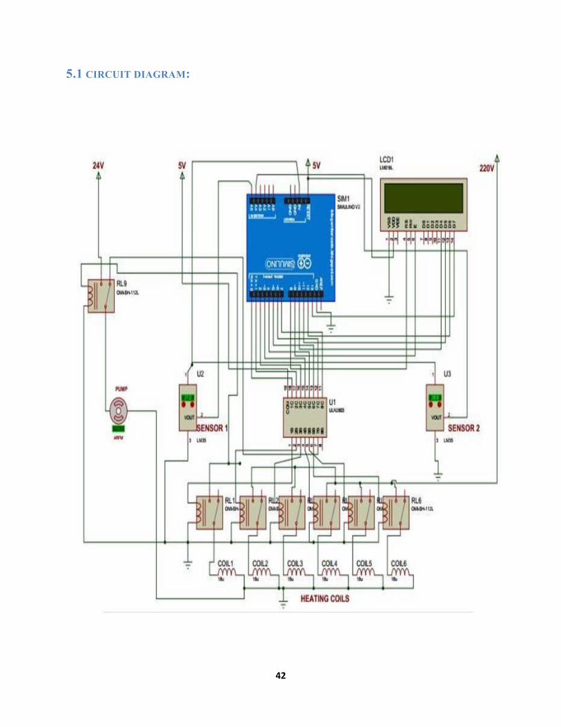
5.1 CIRCUIT DIAGRAM:
43
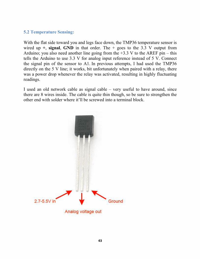
5.2 Temperature Sensing:
With the flat side toward you and legs face down, the TMP36 temperature sensor is wired up +, signal, GND in that order. The + goes to the 3.3 V output from Arduino; you also need another line going from the +3.3 V to the AREF pin – this tells the Arduino to use 3.3 V for analog input reference instead of 5 V. Connect the signal pin of the sensor to A1. In previous attempts, I had used the TMP36 directly on the 5 V line; it works, bit unfortunately when paired with a relay, there was a power drop whenever the relay was activated, resulting in highly fluctuating readings.
I used an old network cable as signal cable – very useful to have around, since there are 8 wires inside. The cable is quite thin though, so be sure to strengthen the other end with solder where it’ll be screwed into a terminal block.
44
Sensed temperature will be shown by using a display. The display will also show different states of the pump and coils. The whole process will be controlled by an arduino. Microprocessor will control the pump and the coils. Temperature probe is actually a unique device on this 1-Wire bus. It is called 1-Wire because a single wire is used to talk to all the devices on the bus – hence using only one pin of your choosing, labeled DQ in the image to the right. These sensors have little chips in them and while they're not that delicate, they do need to be handled properly. Be careful of static electricity when handling them and make sure the power supply is connected up correctly and is between 2.7 and 5.5V DC.
Then, to get the actual temperature, use this formula:
Temperature = ((1.100000001/1024)*temp1)/.01;
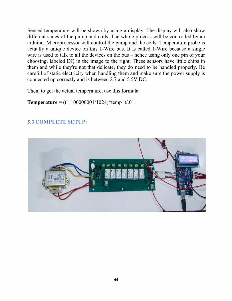
5.3 COMPLETE SETUP:
45
CHAPTER 6
CONTROL LOGIC
Arduino processor can perform certain command written by using arduino standard
library. Here code is written to control the coils and the pump. Codes are explained
in a specific manner below:
6.1 Initialization of variables:
This section of the code is used to initialize of the variables which is necessary to
run the program and control the electric circuit .desired equipment to control in the
circuit is the coils, pump and time .to do so,
Three integer variables (coils, pump and runtime) are initialized.
Sensor 1 and sensor 2 variables are used to receive and send the sensor data to
arduino pins which are defined as a1 and a2.
Coils 1 to 6 are assigned their respective pins through variable assignment.
Required pin for pump is also assigned during runtime.
46
THE THRESHOLD VARIABLE IS THE TEMPERATURE LIMIT WHICH INDICATE THE
CONTROLLING TEMPERATURE. PINS DEFINITION FOR PUMP AND COILS ARE ALSO
DEFINED DURING RUNTIME.

47
6.2 SETUP FUNCTION:
THIS IS THE MAIN FUNCTION WHICH DEFINES THE INPUT AND OUTPUT MODE OF THE
SENSOR ELEMENTS.
Serial begin (9600) doesn't actually print anything. For that you'd want to use Serial print ("Hello world!") to print the text "Hello world!" to the serial console. Rather it initializes the serial connection at 9600 bits per second.
Both sides of the serial connection (i.e. the Arduino and your computer) need to be set to use the same speed serial connection in order to get any sort of intelligible data. If there's a mismatch between what the two systems think the speed is then the data will be garbled.
9600 bits per second is the default for the Arduino, and is perfectly adequate for the majority of users, but you could change it to other speeds: Serial begin (57600) would set the Ardunio to transmit at 57600 bits per second. You'd need to set whatever software you're using on your computer (like the Ardunio IDE's serial monitor) to the same speed in order to see the data being sent.
48
Write a HIGH or a LOW value to a digital pin.
If the pin has been configured as an OUTPUT with pin Mode (), its voltage will be set to the corresponding value: 5V (or 3.3V on 3.3V boards) for HIGH, 0V (ground) for LOW.
If the pin is configured as an INPUT, digital Write () will enable (HIGH) or disable (LOW) the internal pull up on the input pin. It is recommended to set the pin mode () to INPUT_MODE to enable the internal pull-up resistor.
Pin Mode (pin, mode) configures the specified pin to behave either as an input or an output. See the description of digital pin for details on the functionality of the pins.
As of Arduino 1.0.1, it is possible to enable the internal pull up resistors with the mode INPUT_PULLUP. Additionally, the INPUT mode explicitly disables the internal pull ups.
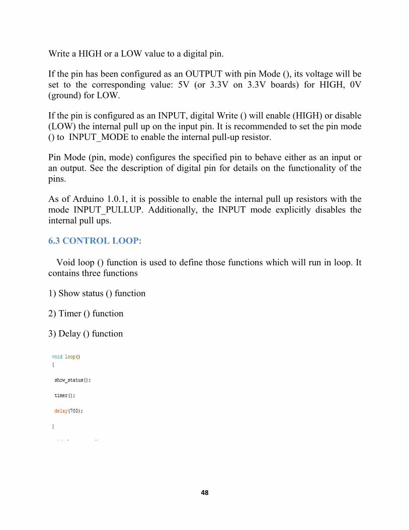
6.3 CONTROL LOOP:
Void loop () function is used to define those functions which will run in loop. It contains three functions
1) Show status () function
2) Timer () function
3) Delay () function
49
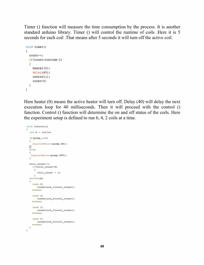
Timer () function will measure the time consumption by the process. It is another standard arduino library. Timer () will control the runtime of coils .Here it is 5 seconds for each coil .That means after 5 seconds it will turn off the active coil.
Here heater (0) means the active heater will turn off. Delay (40) will delay the next execution loop for 40 milliseconds. Then it will proceed with the control () function. Control () function will determine the on and off status of the coils. Here the experiment setup is defined to run 6, 4, 2 coils at a time.
50
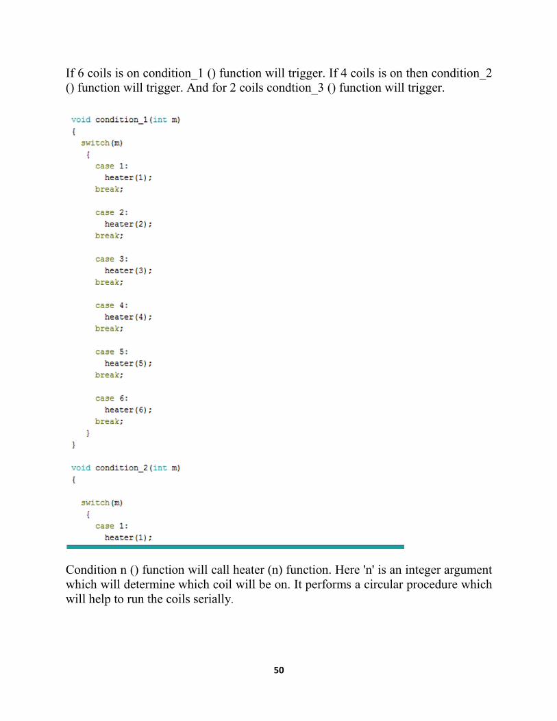
If 6 coils is on condition_1 () function will trigger. If 4 coils is on then condition_2 () function will trigger. And for 2 coils condtion_3 () function will trigger.
Condition n () function will call heater (n) function. Here 'n' is an integer argument which will determine which coil will be on. It performs a circular procedure which will help to run the coils serially.
51
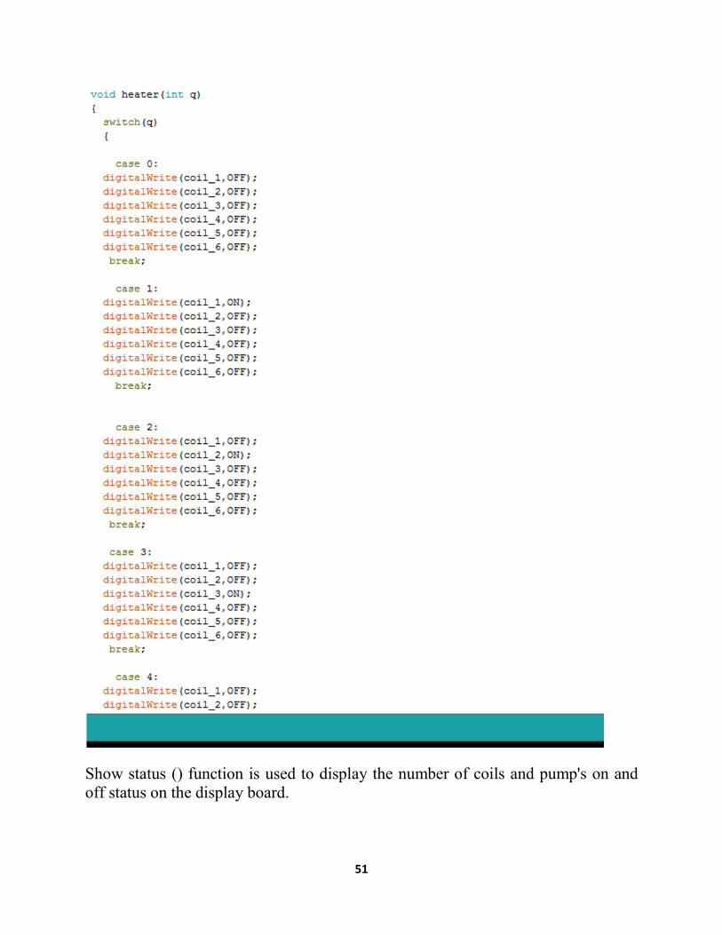
Show status () function is used to display the number of coils and pump's on and off status on the display board.
52
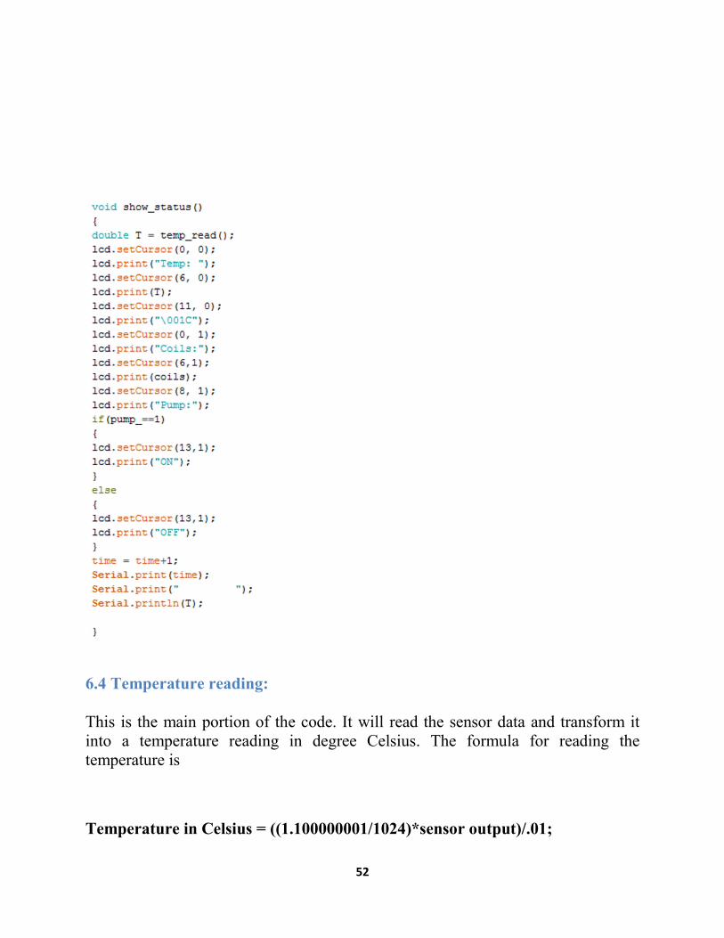
6.4 Temperature reading:
This is the main portion of the code. It will read the sensor data and transform it into a temperature reading in degree Celsius. The formula for reading the temperature is
Temperature in Celsius = ((1.100000001/1024)*sensor output)/.01;

53

54
CHAPTER 7
EXPERIMENT
7.1Experiment:
The control system is designed in such a way that we can run as many coil as we
want. It will depend on the input variable which will hold the number of coils.
Initially it is modified to operate under a condition that includes a limited number
of active coils.
Following experiment should be conducted.
1) Heating with 6 coils on
2) Heating with 4 coils on
3) Heating with 2 coils on
And for cooling:
1) When 6 coils are on there will be water cooling with normal water at room
temperature and cooling with ice water at 0 degree Celsius.
2) When 4 coils are on there will be water cooling with normal water at room
temperature and cooling with ice water at 0 degree Celsius.
3) When 2 coils are on there will be water cooling with normal water at room
temperature and cooling with ice water at 0 degree Celsius.
55
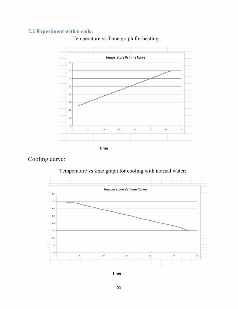
7.2 Experiment with 6 coils:
Temperature vs Time graph for heating:
Time
Cooling curve:
Temperature vs time graph for cooling with normal water:
Time
56
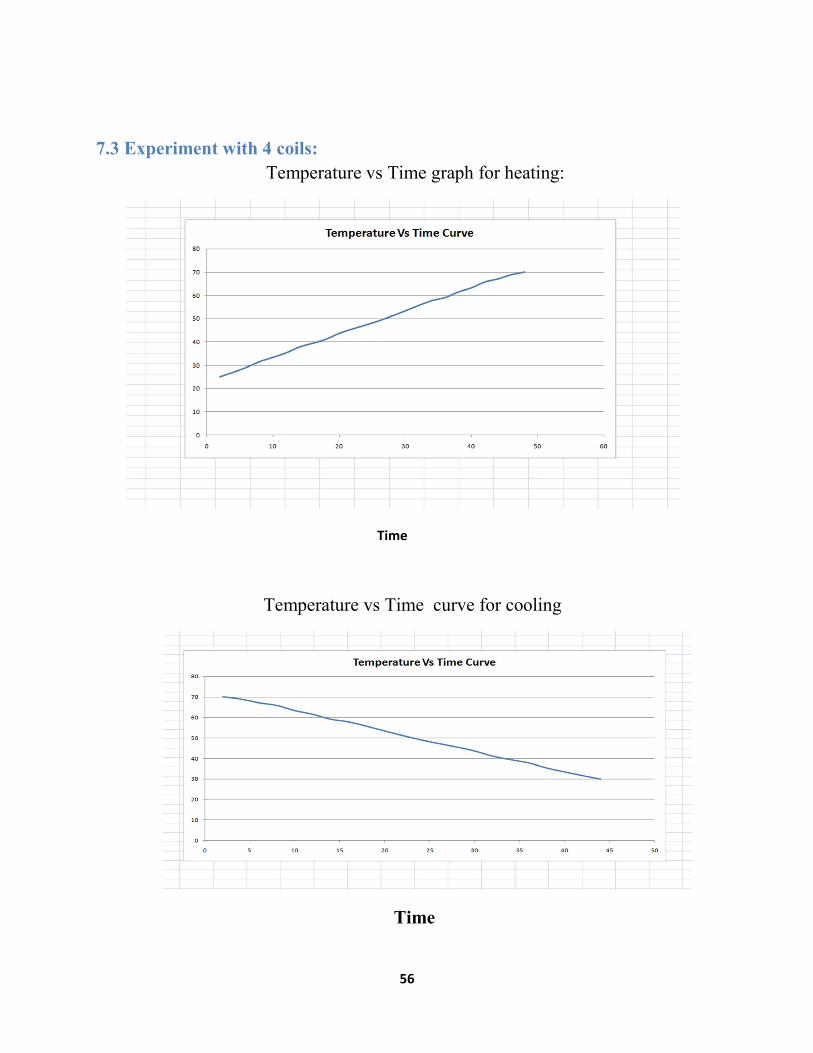
7.3 Experiment with 4 coils:
Temperature vs Time graph for heating:
Time
Temperature vs Time curve for cooling
Time

57
7.4 Experiment with 2 coils :
Temperature vs Time curve for heating:
Temperature vs Time curve for cooling
58
CHAPTER 8
CONCLUSION AND RECOMMENDATIONS
8.1 Conclusion
This experiment was designed in such a way that it includes both design of a
industrial type pressure vessel and temperature control using a suitable control
system. In a nutshell the aspects of this project are:
1) Being able to design of pressure vessel with precise calculation.
2) Manufacture all the designed parts according to this calculation.
3) Design an electrical control system and assemble the parts.
4) Writing a microprocessor code which will be the actual brain behind all the
process
The experiment should be done in properly controlled environment. To get
accurate date the vessel must be completely closed so that no leakage can happen.
8.2 Recommendation:
More experimental data should be collected for better precision of the graph.
For further experiment it is recommended to keep the coil power as low as possible
to acquire more precise control. Also more importance should be given to agitation
as it will help proper temperature distribution throughout the liquid.

59
Reference
A.C. Ugural, S.K. Fenster, Advanced Strength and Applied Elasticity, 4th ed.
E.P. Popov, Engineering Mechanics of Solids, 1st ed.
Megyesy, Eugene F. (2008, 14th ed.) Pressure Vessel Handbook. PV Publishing, Inc.: Oklahoma City, Oklahoma, USA. www.pressurevesselhandbook.com Design handbook for pressure vessels based on the ASME code.
Pressure Vessel attachments http://oakridgebellows.com/metal-expansion-joints/technical-videos/lugs-on-pipe-and-vessels-new
Related Documents