TECHNICAL NOTE On Cold-Formed Steel Construction 1201 15th Street, NW, Suite 320 W ashington, DC 20005 (202) 785-2022 $5.00 DESIGN AIDS AND EXAMPLES FOR DISTORTIONAL BUCKLING The latest edition of AISI-S100 (2007) has added new design checks for distortional buckling of cold-formed steel members in bending (Section C3.1.4) and compression (Section C4.2). As presented in the AISI-S100 commentary, distortional buckling is a mode of buckling in which the lip stiffener is insufficient to retard the compression flange and attached web from becoming unstable. The in-plane deformations that occur in distortional buckling are contrasted with those of local and lateral-torsional buckling for a member in bending in Figure 1. INTRODUCTION Cold-Formed Steel Engineers Institute TECH NOTE G100-08 September 2008 1 Summary: The objective of this Tech Note is to provide design examples and design aids specific to cold-formed steel framing systems that address the new distortional buckling limit states added to AISI-S100 in the 2007 edition. In addition, a method is provided for including rotational restraint, provided by sheathing to members, in the design calculations for distortional buckling. This method has been proposed for the next edition of AISI-S210 (floors and roofs) and AISI-S211 (walls studs) standards and partially mitigates the reduced capacity in the distortional buckling limit state. FIGURE 1 For many conventional bending members (e.g., floor joists) distortional buckling may now control the design strength DISTORTIONAL BUCKLING IN BENDING OR COMPRESSION (i.e., the provisions of C3.1.4 for distortional buckling provide a smaller predicted capacity than those of C3.1.1 for the nominal section strength or C3.1.2 for lateral-torsional buckling). This is particularly true for joists designed with a continuously braced design philosophy - in that case lateral- torsional buckling is fully restricted and only the local buckling (effective width) reductions are applied to the member. Unfortunately, checking distortional buckling to determine if it controls the design capacity can require significant effort. To simplify this process design aids and design examples are provided in this Tech Note. Compression members are also subject to distortional buckling and must be checked per the provisions of C4.2 in AISI-S100. However, in compression, even when a sheathing braced design philosophy is detailed and flexural and flexural- torsional buckling are essentially restricted, local buckling of SSMA sections commonly provides a capacity lower than

Welcome message from author
This document is posted to help you gain knowledge. Please leave a comment to let me know what you think about it! Share it to your friends and learn new things together.
Transcript
TECHNICAL NOTEOn Cold-Formed Steel Construction1201 15th Street, NW, Suite 320 W ashington, DC 20005 (202) 785-2022
$5.00
DESIGN AIDS AND EXAMPLES FORDISTORTIONAL BUCKLING
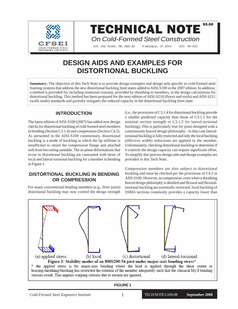
The latest edition of AISI-S100 (2007) has added new designchecks for distortional buckling of cold-formed steel membersin bending (Section C3.1.4) and compression (Section C4.2).As presented in the AISI-S100 commentary, distortionalbuckling is a mode of buckling in which the lip stiffener isinsufficient to retard the compression flange and attachedweb from becoming unstable. The in-plane deformations thatoccur in distortional buckling are contrasted with those oflocal and lateral-torsional buckling for a member in bendingin Figure 1.
INTRODUCTION
Cold-Formed Steel Engineers Institute TECH NOTE G100-08 September 20081
Summary: The objective of this Tech Note is to provide design examples and design aids specific to cold-formed steelframing systems that address the new distortional buckling limit states added to AISI-S100 in the 2007 edition. In addition,a method is provided for including rotational restraint, provided by sheathing to members, in the design calculations fordistortional buckling. This method has been proposed for the next edition of AISI-S210 (floors and roofs) and AISI-S211(walls studs) standards and partially mitigates the reduced capacity in the distortional buckling limit state.
FIGURE 1
For many conventional bending members (e.g., floor joists)distortional buckling may now control the design strength
DISTORTIONAL BUCKLING IN BENDINGOR COMPRESSION
(i.e., the provisions of C3.1.4 for distortional buckling providea smaller predicted capacity than those of C3.1.1 for thenominal section strength or C3.1.2 for lateral-torsionalbuckling). This is particularly true for joists designed with acontinuously braced design philosophy - in that case lateral-torsional buckling is fully restricted and only the local buckling(effective width) reductions are applied to the member.Unfortunately, checking distortional buckling to determine ifit controls the design capacity can require significant effort.To simplify this process design aids and design examples areprovided in this Tech Note.
Compression members are also subject to distortionalbuckling and must be checked per the provisions of C4.2 inAISI-S100. However, in compression, even when a sheathingbraced design philosophy is detailed and flexural and flexural-torsional buckling are essentially restricted, local buckling ofSSMA sections commonly provides a capacity lower than
TECH NOTE G100-08 September 2008 Cold-Formed Steel Engineers Institute2
distortional buckling. Thus, the focus of this Technical Noteis on bending members, though the design aid does apply tocompression members.
DETERMINING THE ELASTICDISTORTIONAL BUCKING STRESS
The key step in the AISI-S100 distortional bucklingprovisions is the determination of the elastic distortionalbuckling stress, F
d. For standard SSMA sections F
d is
tabled using the applicable AISI-S100 provisions in thedesign aid of this Note. Alternatively, as demonstrated inthe design example, rational elastic buckling analysis fordetermining F
d may be performed using freely available
open source software. However, the Fd reported in the
design aid ignores a key benefit of typical cold-formedsteel framing systems: resistance to distortional bucklingprovided by attached sheathing.
The AISI-S100 provisions for distortional buckling providea means to include a supplemental rotational restraint, kφ,in the prediction equations. However, little guidance isprovided on what value to use for this stiffness. Recently,through AISI-COFS funding, Schafer et al. (2007, 2008)tested a variety of common sheathing details andproposed a design method for determination of kφ. Thisdesign method, provided in the following sections anddetailed in the design example, is recommended for use asa rational engineering analysis in the determination of kφuntil such time as it is adopted in the COFS standards.
PROPOSED METHOD FORDETERMINING Kφφφφφ
The following provides the method for determining therotational stiffness in “proposed” Specification language:
Calculation of the nominal distortional buckling strength inflexure per C3.1.4 of AISI S100, or per Appendix 1 of AISIS100 may utilize the beneficial system affect of sheathingfastened to the compression flange of floor joists, ceilingjoists, roof rafters, or wall studs through the calculation ofthe rotational stiffness provided to the bending member, kφ.
Calculation of the nominal distortional buckling strengthin compression per C4.2 of AISI S100, or per Appendix 1of AISI S100 may utilize the beneficial system affect ofsheathing fastened to both flanges of floor joists,ceiling joists, roof rafters, or wall studs through thecalculation of the rotational stiffness provided to thebending member, kφ.
The rotational stiffness kf shall be determined via
kφ= (1/kφw + 1/kφc
)-1 (1)
where the sheathing rotational restraint kφw is calculated
for interior members (joists or rafters) with sheathingfastened on both sides as
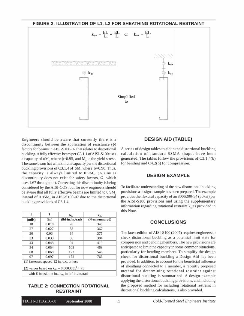
kφw = EI
w/L
1 + EI
w/L
2 (2)
for exterior members, or members with sheathingfastened on one side as
kφw = EI
w/L
1 (3)
and:EI
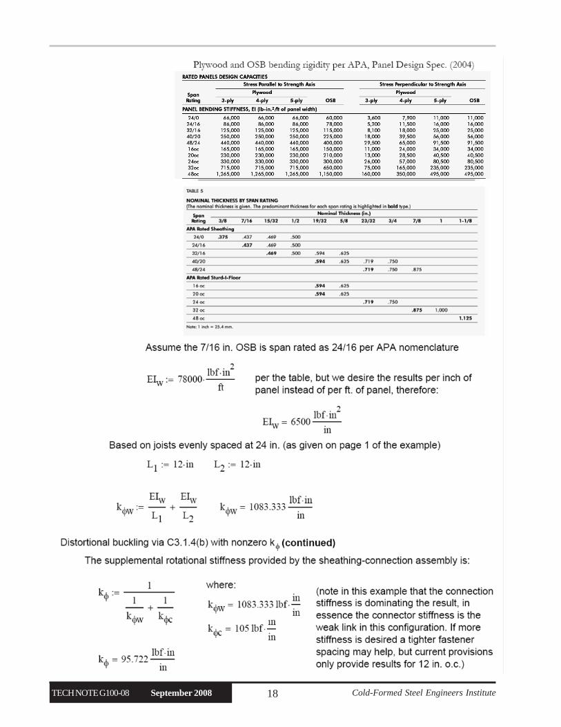
w = sheathing bending rigidity,
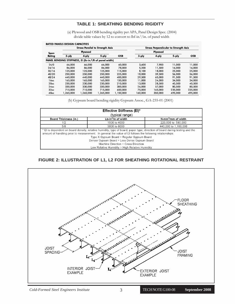
for plywood and OSB use APA (2004) as given inTable 1(a),for gypsum board use min values of GA (2001) asgiven in Table 1(b);note, gypsum may be used for serviceability, butnot for ultimate strength
L1, L
2 = one half the joist spacing to the first and second sides
respectively, as illustrated in Figure 2 where the connection rotational restraint kφc
is calculatedfor fasteners spaced 12 in. o.c. or closer in plywood,OSB, or gypsum
kφc = values per Table 2 (4)
PRACTICAL GUIDANCE REGARDINGDISTORTIONAL BUCKLING
It is important to note, that even with the additional guidanceprovided here distortional buckling may still control the designstrength of some commonly used SSMA sections, particularlyin bending. The primary variable for improving distortionalbuckling resistance is a longer lip stiffener, but this is outsideof the engineer’s control.
Increasing kφ with the goal of removing distortionalbuckling may also be impractical. The rotational restraintprovided by the sheathing is commonly limited by theflange-to-sheathing connection stiffness (kφc). Thisrestraint is primarily influenced by the thickness of themember, and thus is not easily increased withoutsignificant cost. A fastener spacing tighter than 12 in. o.c.was shown to increase kφ (Schafer et al 2007) but thetesting was too limited to generalize the results.
Increased member thickness increases restraint, kφ, and thedistortional buckling stress, F
d. However, increased member
thickness also increases local buckling resistance - typicallyat a faster rate. Thus, thicker members are often more likely tohave a distortional buckling resistance which is less than thelocal buckling resistance.
Cold-Formed Steel Engineers Institute TECH NOTE G100-08 September 20083
TABLE 1: SHEATHING BENDING RIGIDITY
FIGURE 2: ILLUSTRATION OF L1, L2 FOR SHEATHING ROTATIONAL RESTRAINT
(a) Plywood and OSB bending rigidity per APA, Panel Design Spec. (2004)divide table values by 12 to convert to lbf-in.2/in. of panel width
(b) Gypsum board bending rigidity Gypsum Assoc., GA-235-01 (2001)
TECH NOTE G100-08 September 2008 Cold-Formed Steel Engineers Institute4
TABLE 2: CONNECTION ROTATIONALRESTRAINT
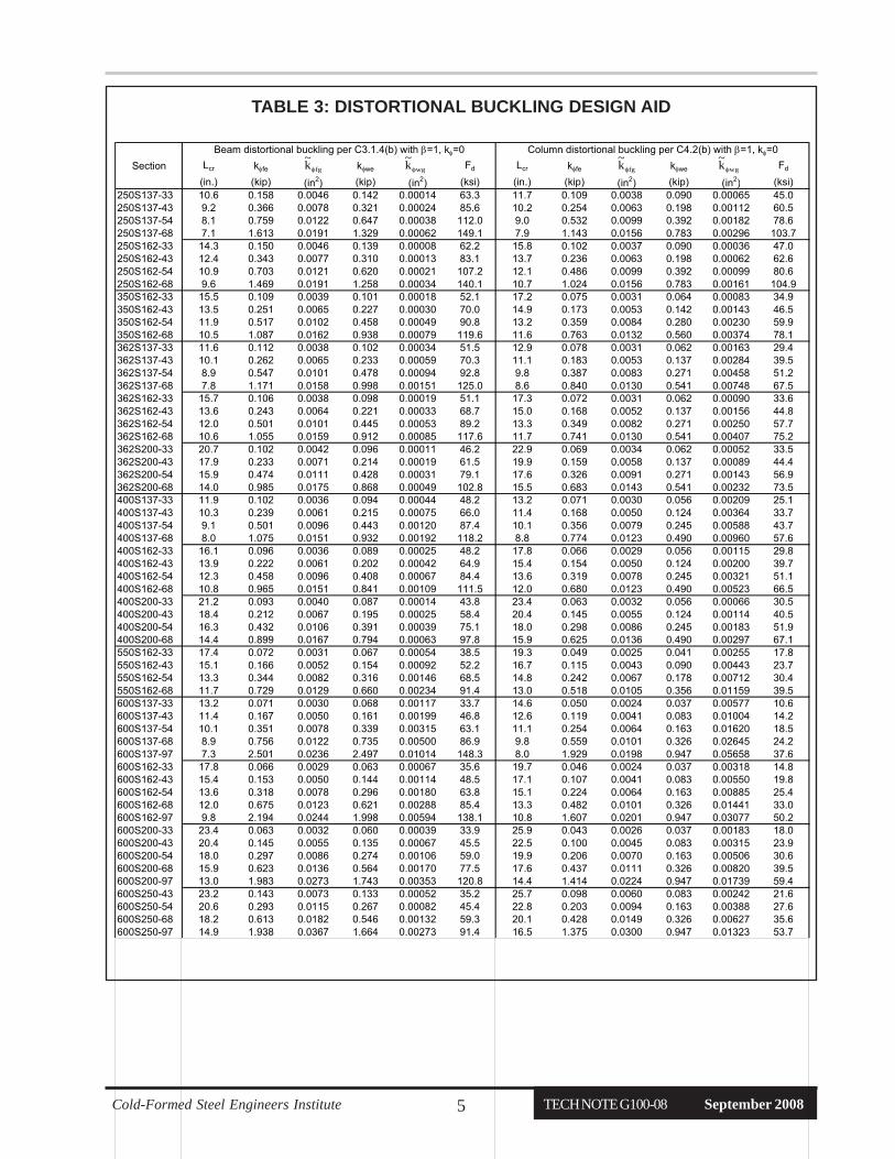
DESIGN AID (TABLE)
A series of design tables to aid in the distortional bucklingcalculation of standard SSMA shapes have beengenerated. The tables follow the provisions of C3.1.4(b)for bending and C4.2(b) for compression.
DESIGN EXAMPLE
CONCLUSIONS
To facilitate understanding of the new distortional bucklingprovisions a design example has been prepared. The exampleprovides the flexural capacity of an 800S200-54 (50ksi) perthe AISI-S100 provisions and using the supplementaryinformation regarding rotational restraint kφ as provided inthis Note.
The latest edition of AISI-S100 (2007) requires engineers tocheck distortional buckling as a potential limit state forcompression and bending members. The new provisions areanticipated to limit the capacity in some common situations,particularly for bending members. To simplify the designcheck for distortional buckling a Design Aid has beenprovided. In addition, to account for the beneficial influenceof sheathing connected to a member, a recently proposedmethod for determining rotational restraint againstdistortional buckling is summarized. A design exampleapplying the distortional buckling provisions, and includingthe proposed method for including rotational restraint indistortional buckling calculations, is also provided.
Engineers should be aware that currently there is adiscontinuity between the application of resistance (φ)factors for beams in AISI-S100-07 that relates to distortionalbuckling. A fully effective beam per C3.1.1 of AISI-S100 usesa capacity of φM
y where φ=0.95, and M
y is the yield stress.
The same beam has a maximum capacity per the distortionalbuckling provisions of C3.1.4 of φM
y where φ=0.90. Thus,
the capacity is always limited to 0.9My. (A similar
discontinuity does not exist for safety factors, Ω, whichuses 1.67 throughout). Correcting this discontinuity is beingconsidered by the AISI-COS, but for now engineers shouldbe aware that all fully effective beams are limited to 0.9M
y
instead of 0.95My in AISI-S100-07 due to the distortional
buckling provisions of C3.1.4.
t t kφc kφc
(mils) (in.) (lbf-in./in./rad) (N-mm/mm/rad)
18 0.018 78 348 27 0.027 83 367 30 0.03 84 375 33 0.033 86 384 43 0.043 94 419 54 0.054 105 468 68 0.068 123 546 97 0.097 172 766
(1) fasteners spaced 12 in. o.c. or less
(2) values based on kφc = 0.00035Et2 + 75
with E in psi, t in in., kφc in lbf-in./in./rad
FIGURE 2: ILLUSTRATION OF L1, L2 FOR SHEATHING ROTATIONAL RESTRAINT
Cold-Formed Steel Engineers Institute TECH NOTE G100-08 September 20085
Beam distortional buckling per C3.1.4(b) with β=1, kφ=0 Column distortional buckling per C4.2(b) with β=1, kφ=0
Section Lcr kφfe kφfg kφwe kφwg Fd Lcr kφfe kφfg kφwe kφwg Fd
(in.) (kip) (in2) (kip) (in2) (ksi) (in.) (kip) (in2) (kip) (in2) (ksi)250S137-33 10.6 0.158 0.0046 0.142 0.00014 63.3 11.7 0.109 0.0038 0.090 0.00065 45.0250S137-43 9.2 0.366 0.0078 0.321 0.00024 85.6 10.2 0.254 0.0063 0.198 0.00112 60.5250S137-54 8.1 0.759 0.0122 0.647 0.00038 112.0 9.0 0.532 0.0099 0.392 0.00182 78.6250S137-68 7.1 1.613 0.0191 1.329 0.00062 149.1 7.9 1.143 0.0156 0.783 0.00296 103.7250S162-33 14.3 0.150 0.0046 0.139 0.00008 62.2 15.8 0.102 0.0037 0.090 0.00036 47.0250S162-43 12.4 0.343 0.0077 0.310 0.00013 83.1 13.7 0.236 0.0063 0.198 0.00062 62.6250S162-54 10.9 0.703 0.0121 0.620 0.00021 107.2 12.1 0.486 0.0099 0.392 0.00099 80.6250S162-68 9.6 1.469 0.0191 1.258 0.00034 140.1 10.7 1.024 0.0156 0.783 0.00161 104.9350S162-33 15.5 0.109 0.0039 0.101 0.00018 52.1 17.2 0.075 0.0031 0.064 0.00083 34.9350S162-43 13.5 0.251 0.0065 0.227 0.00030 70.0 14.9 0.173 0.0053 0.142 0.00143 46.5350S162-54 11.9 0.517 0.0102 0.458 0.00049 90.8 13.2 0.359 0.0084 0.280 0.00230 59.9350S162-68 10.5 1.087 0.0162 0.938 0.00079 119.6 11.6 0.763 0.0132 0.560 0.00374 78.1362S137-33 11.6 0.112 0.0038 0.102 0.00034 51.5 12.9 0.078 0.0031 0.062 0.00163 29.4362S137-43 10.1 0.262 0.0065 0.233 0.00059 70.3 11.1 0.183 0.0053 0.137 0.00284 39.5362S137-54 8.9 0.547 0.0101 0.478 0.00094 92.8 9.8 0.387 0.0083 0.271 0.00458 51.2362S137-68 7.8 1.171 0.0158 0.998 0.00151 125.0 8.6 0.840 0.0130 0.541 0.00748 67.5362S162-33 15.7 0.106 0.0038 0.098 0.00019 51.1 17.3 0.072 0.0031 0.062 0.00090 33.6362S162-43 13.6 0.243 0.0064 0.221 0.00033 68.7 15.0 0.168 0.0052 0.137 0.00156 44.8362S162-54 12.0 0.501 0.0101 0.445 0.00053 89.2 13.3 0.349 0.0082 0.271 0.00250 57.7362S162-68 10.6 1.055 0.0159 0.912 0.00085 117.6 11.7 0.741 0.0130 0.541 0.00407 75.2362S200-33 20.7 0.102 0.0042 0.096 0.00011 46.2 22.9 0.069 0.0034 0.062 0.00052 33.5362S200-43 17.9 0.233 0.0071 0.214 0.00019 61.5 19.9 0.159 0.0058 0.137 0.00089 44.4362S200-54 15.9 0.474 0.0111 0.428 0.00031 79.1 17.6 0.326 0.0091 0.271 0.00143 56.9362S200-68 14.0 0.985 0.0175 0.868 0.00049 102.8 15.5 0.683 0.0143 0.541 0.00232 73.5400S137-33 11.9 0.102 0.0036 0.094 0.00044 48.2 13.2 0.071 0.0030 0.056 0.00209 25.1400S137-43 10.3 0.239 0.0061 0.215 0.00075 66.0 11.4 0.168 0.0050 0.124 0.00364 33.7400S137-54 9.1 0.501 0.0096 0.443 0.00120 87.4 10.1 0.356 0.0079 0.245 0.00588 43.7400S137-68 8.0 1.075 0.0151 0.932 0.00192 118.2 8.8 0.774 0.0123 0.490 0.00960 57.6400S162-33 16.1 0.096 0.0036 0.089 0.00025 48.2 17.8 0.066 0.0029 0.056 0.00115 29.8400S162-43 13.9 0.222 0.0061 0.202 0.00042 64.9 15.4 0.154 0.0050 0.124 0.00200 39.7400S162-54 12.3 0.458 0.0096 0.408 0.00067 84.4 13.6 0.319 0.0078 0.245 0.00321 51.1400S162-68 10.8 0.965 0.0151 0.841 0.00109 111.5 12.0 0.680 0.0123 0.490 0.00523 66.5400S200-33 21.2 0.093 0.0040 0.087 0.00014 43.8 23.4 0.063 0.0032 0.056 0.00066 30.5400S200-43 18.4 0.212 0.0067 0.195 0.00025 58.4 20.4 0.145 0.0055 0.124 0.00114 40.5400S200-54 16.3 0.432 0.0106 0.391 0.00039 75.1 18.0 0.298 0.0086 0.245 0.00183 51.9400S200-68 14.4 0.899 0.0167 0.794 0.00063 97.8 15.9 0.625 0.0136 0.490 0.00297 67.1550S162-33 17.4 0.072 0.0031 0.067 0.00054 38.5 19.3 0.049 0.0025 0.041 0.00255 17.8550S162-43 15.1 0.166 0.0052 0.154 0.00092 52.2 16.7 0.115 0.0043 0.090 0.00443 23.7550S162-54 13.3 0.344 0.0082 0.316 0.00146 68.5 14.8 0.242 0.0067 0.178 0.00712 30.4550S162-68 11.7 0.729 0.0129 0.660 0.00234 91.4 13.0 0.518 0.0105 0.356 0.01159 39.5600S137-33 13.2 0.071 0.0030 0.068 0.00117 33.7 14.6 0.050 0.0024 0.037 0.00577 10.6600S137-43 11.4 0.167 0.0050 0.161 0.00199 46.8 12.6 0.119 0.0041 0.083 0.01004 14.2600S137-54 10.1 0.351 0.0078 0.339 0.00315 63.1 11.1 0.254 0.0064 0.163 0.01620 18.5600S137-68 8.9 0.756 0.0122 0.735 0.00500 86.9 9.8 0.559 0.0101 0.326 0.02645 24.2600S137-97 7.3 2.501 0.0236 2.497 0.01014 148.3 8.0 1.929 0.0198 0.947 0.05658 37.6600S162-33 17.8 0.066 0.0029 0.063 0.00067 35.6 19.7 0.046 0.0024 0.037 0.00318 14.8600S162-43 15.4 0.153 0.0050 0.144 0.00114 48.5 17.1 0.107 0.0041 0.083 0.00550 19.8600S162-54 13.6 0.318 0.0078 0.296 0.00180 63.8 15.1 0.224 0.0064 0.163 0.00885 25.4600S162-68 12.0 0.675 0.0123 0.621 0.00288 85.4 13.3 0.482 0.0101 0.326 0.01441 33.0600S162-97 9.8 2.194 0.0244 1.998 0.00594 138.1 10.8 1.607 0.0201 0.947 0.03077 50.2600S200-33 23.4 0.063 0.0032 0.060 0.00039 33.9 25.9 0.043 0.0026 0.037 0.00183 18.0600S200-43 20.4 0.145 0.0055 0.135 0.00067 45.5 22.5 0.100 0.0045 0.083 0.00315 23.9600S200-54 18.0 0.297 0.0086 0.274 0.00106 59.0 19.9 0.206 0.0070 0.163 0.00506 30.6600S200-68 15.9 0.623 0.0136 0.564 0.00170 77.5 17.6 0.437 0.0111 0.326 0.00820 39.5600S200-97 13.0 1.983 0.0273 1.743 0.00353 120.8 14.4 1.414 0.0224 0.947 0.01739 59.4600S250-43 23.2 0.143 0.0073 0.133 0.00052 35.2 25.7 0.098 0.0060 0.083 0.00242 21.6600S250-54 20.6 0.293 0.0115 0.267 0.00082 45.4 22.8 0.203 0.0094 0.163 0.00388 27.6600S250-68 18.2 0.613 0.0182 0.546 0.00132 59.3 20.1 0.428 0.0149 0.326 0.00627 35.6600S250-97 14.9 1.938 0.0367 1.664 0.00273 91.4 16.5 1.375 0.0300 0.947 0.01323 53.7
fgk~φ wgk
~φ fgk
~φ wgk
~φ
TABLE 3: DISTORTIONAL BUCKLING DESIGN AID
TECH NOTE G100-08 September 2008 Cold-Formed Steel Engineers Institute6
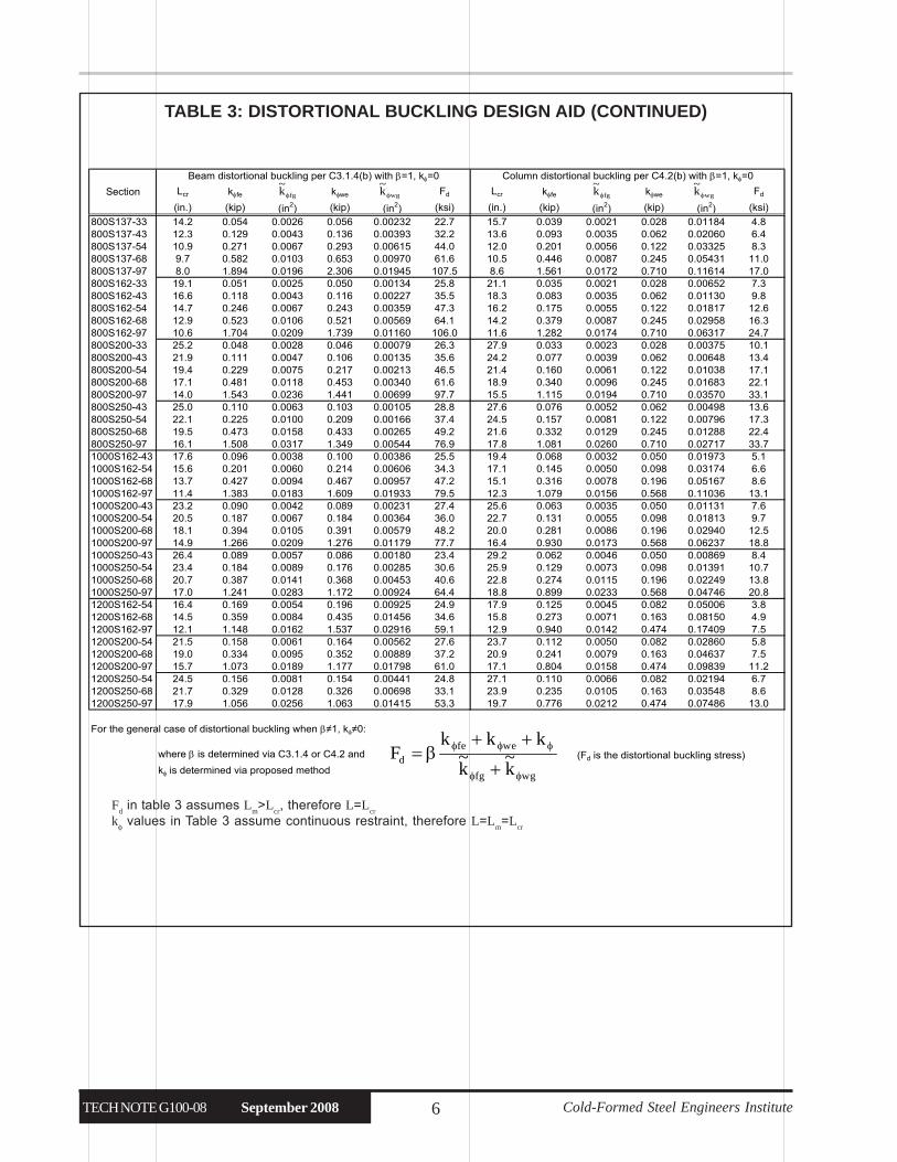
800S137-33 14.2 0.054 0.0026 0.056 0.00232 22.7 15.7 0.039 0.0021 0.028 0.01184 4.8800S137-43 12.3 0.129 0.0043 0.136 0.00393 32.2 13.6 0.093 0.0035 0.062 0.02060 6.4800S137-54 10.9 0.271 0.0067 0.293 0.00615 44.0 12.0 0.201 0.0056 0.122 0.03325 8.3800S137-68 9.7 0.582 0.0103 0.653 0.00970 61.6 10.5 0.446 0.0087 0.245 0.05431 11.0800S137-97 8.0 1.894 0.0196 2.306 0.01945 107.5 8.6 1.561 0.0172 0.710 0.11614 17.0800S162-33 19.1 0.051 0.0025 0.050 0.00134 25.8 21.1 0.035 0.0021 0.028 0.00652 7.3800S162-43 16.6 0.118 0.0043 0.116 0.00227 35.5 18.3 0.083 0.0035 0.062 0.01130 9.8800S162-54 14.7 0.246 0.0067 0.243 0.00359 47.3 16.2 0.175 0.0055 0.122 0.01817 12.6800S162-68 12.9 0.523 0.0106 0.521 0.00569 64.1 14.2 0.379 0.0087 0.245 0.02958 16.3800S162-97 10.6 1.704 0.0209 1.739 0.01160 106.0 11.6 1.282 0.0174 0.710 0.06317 24.7800S200-33 25.2 0.048 0.0028 0.046 0.00079 26.3 27.9 0.033 0.0023 0.028 0.00375 10.1800S200-43 21.9 0.111 0.0047 0.106 0.00135 35.6 24.2 0.077 0.0039 0.062 0.00648 13.4800S200-54 19.4 0.229 0.0075 0.217 0.00213 46.5 21.4 0.160 0.0061 0.122 0.01038 17.1800S200-68 17.1 0.481 0.0118 0.453 0.00340 61.6 18.9 0.340 0.0096 0.245 0.01683 22.1800S200-97 14.0 1.543 0.0236 1.441 0.00699 97.7 15.5 1.115 0.0194 0.710 0.03570 33.1800S250-43 25.0 0.110 0.0063 0.103 0.00105 28.8 27.6 0.076 0.0052 0.062 0.00498 13.6800S250-54 22.1 0.225 0.0100 0.209 0.00166 37.4 24.5 0.157 0.0081 0.122 0.00796 17.3800S250-68 19.5 0.473 0.0158 0.433 0.00265 49.2 21.6 0.332 0.0129 0.245 0.01288 22.4800S250-97 16.1 1.508 0.0317 1.349 0.00544 76.9 17.8 1.081 0.0260 0.710 0.02717 33.71000S162-43 17.6 0.096 0.0038 0.100 0.00386 25.5 19.4 0.068 0.0032 0.050 0.01973 5.11000S162-54 15.6 0.201 0.0060 0.214 0.00606 34.3 17.1 0.145 0.0050 0.098 0.03174 6.61000S162-68 13.7 0.427 0.0094 0.467 0.00957 47.2 15.1 0.316 0.0078 0.196 0.05167 8.61000S162-97 11.4 1.383 0.0183 1.609 0.01933 79.5 12.3 1.079 0.0156 0.568 0.11036 13.11000S200-43 23.2 0.090 0.0042 0.089 0.00231 27.4 25.6 0.063 0.0035 0.050 0.01131 7.61000S200-54 20.5 0.187 0.0067 0.184 0.00364 36.0 22.7 0.131 0.0055 0.098 0.01813 9.71000S200-68 18.1 0.394 0.0105 0.391 0.00579 48.2 20.0 0.281 0.0086 0.196 0.02940 12.51000S200-97 14.9 1.266 0.0209 1.276 0.01179 77.7 16.4 0.930 0.0173 0.568 0.06237 18.81000S250-43 26.4 0.089 0.0057 0.086 0.00180 23.4 29.2 0.062 0.0046 0.050 0.00869 8.41000S250-54 23.4 0.184 0.0089 0.176 0.00285 30.6 25.9 0.129 0.0073 0.098 0.01391 10.71000S250-68 20.7 0.387 0.0141 0.368 0.00453 40.6 22.8 0.274 0.0115 0.196 0.02249 13.81000S250-97 17.0 1.241 0.0283 1.172 0.00924 64.4 18.8 0.899 0.0233 0.568 0.04746 20.81200S162-54 16.4 0.169 0.0054 0.196 0.00925 24.9 17.9 0.125 0.0045 0.082 0.05006 3.81200S162-68 14.5 0.359 0.0084 0.435 0.01456 34.6 15.8 0.273 0.0071 0.163 0.08150 4.91200S162-97 12.1 1.148 0.0162 1.537 0.02916 59.1 12.9 0.940 0.0142 0.474 0.17409 7.51200S200-54 21.5 0.158 0.0061 0.164 0.00562 27.6 23.7 0.112 0.0050 0.082 0.02860 5.81200S200-68 19.0 0.334 0.0095 0.352 0.00889 37.2 20.9 0.241 0.0079 0.163 0.04637 7.51200S200-97 15.7 1.073 0.0189 1.177 0.01798 61.0 17.1 0.804 0.0158 0.474 0.09839 11.21200S250-54 24.5 0.156 0.0081 0.154 0.00441 24.8 27.1 0.110 0.0066 0.082 0.02194 6.71200S250-68 21.7 0.329 0.0128 0.326 0.00698 33.1 23.9 0.235 0.0105 0.163 0.03548 8.61200S250-97 17.9 1.056 0.0256 1.063 0.01415 53.3 19.7 0.776 0.0212 0.474 0.07486 13.0
For the general case of distortional buckling when β≠1, kφ≠0:
where β is determined via C3.1.4 or C4.2 and (Fd is the distortional buckling stress)
kφ is determined via proposed method wgfg
wefed
k~
k~
kkkF
φφ
φφφ
+
++β=
Beam distortional buckling per C3.1.4(b) with β=1, kφ=0 Column distortional buckling per C4.2(b) with β=1, kφ=0
Section Lcr kφfe kφfg kφwe kφwg Fd Lcr kφfe kφfg kφwe kφwg Fd
(in.) (kip) (in2) (kip) (in2) (ksi) (in.) (kip) (in2) (kip) (in2) (ksi)fgk
~φ wgk
~φ fgk
~φ wgk
~φ
TABLE 3: DISTORTIONAL BUCKLING DESIGN AID (CONTINUED)
Fd in table 3 assumes L
m>L
cr, therefore L=L
cr
kφ values in Table 3 assume continuous restraint, therefore L=Lm=L
cr
Cold-Formed Steel Engineers Institute TECH NOTE G100-08 September 20087
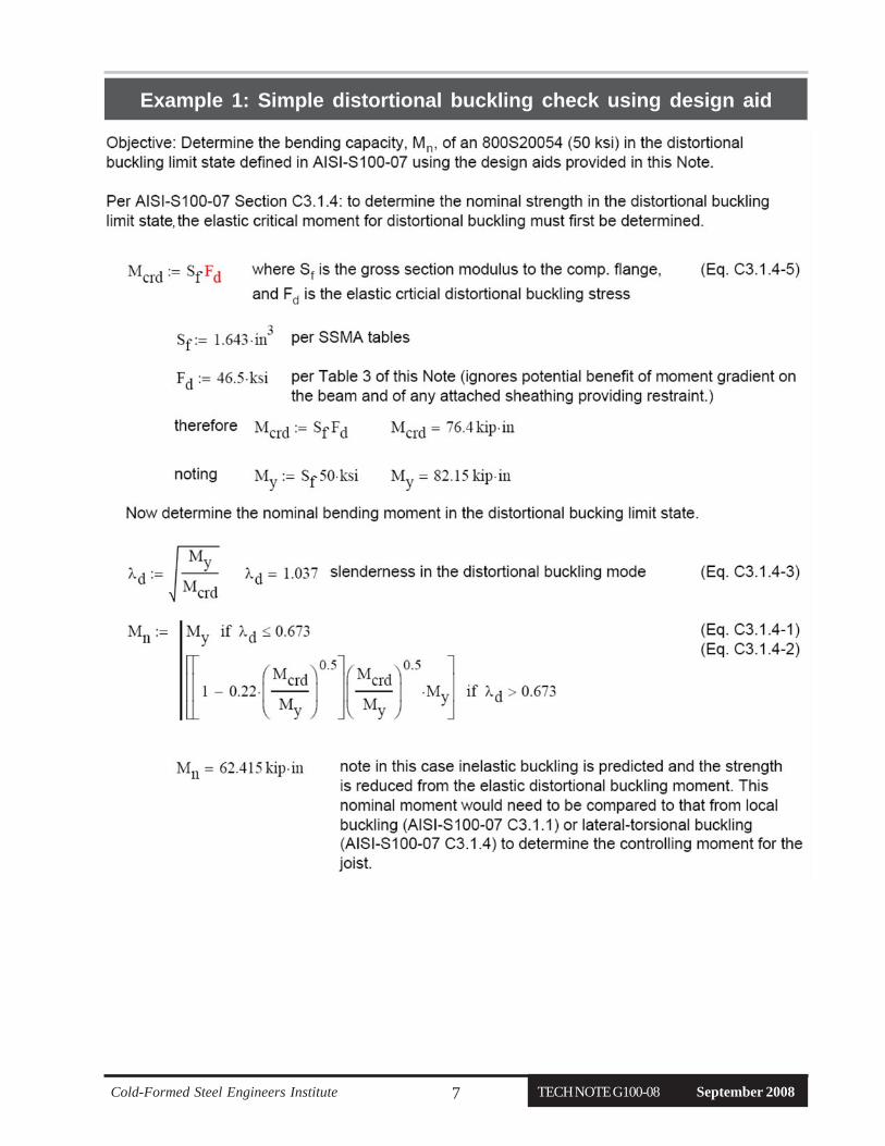
Example 1: Simple distortional buckling check using design aid
,
TECH NOTE G100-08 September 2008 Cold-Formed Steel Engineers Institute8
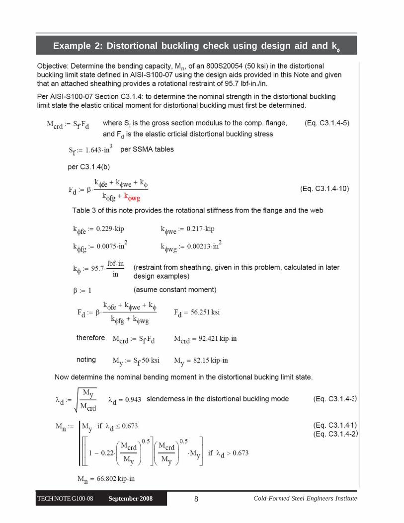
Example 2: Distortional buckling check using design aid and kφφφφφ

Cold-Formed Steel Engineers Institute TECH NOTE G100-08 September 20089
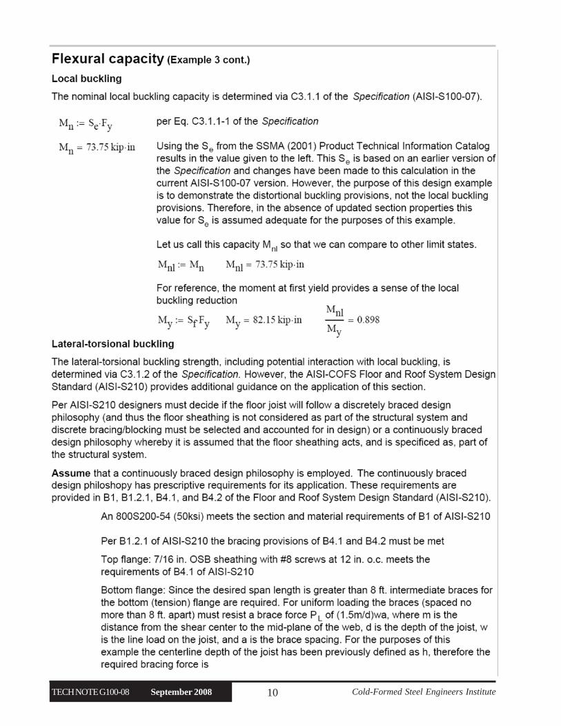
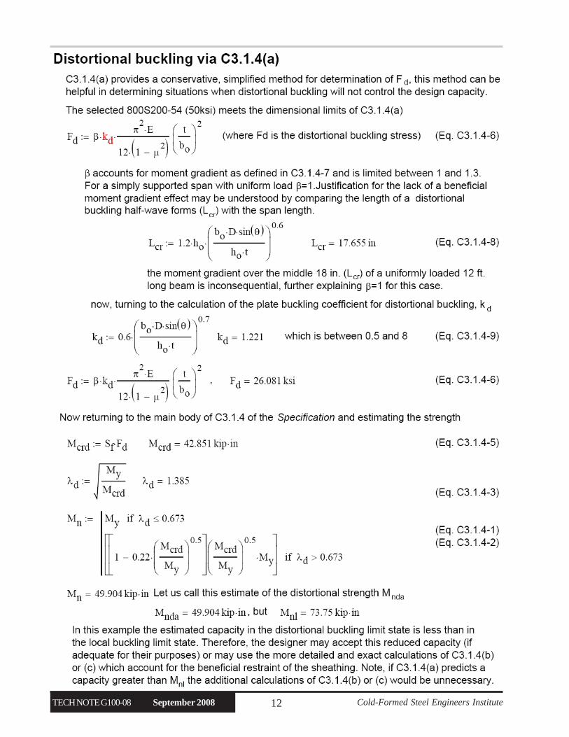
Example 3: Full floor joist design considering distortional buckling
TECH NOTE G100-08 September 2008 Cold-Formed Steel Engineers Institute10

Cold-Formed Steel Engineers Institute TECH NOTE G100-08 September 200811
TECH NOTE G100-08 September 2008 Cold-Formed Steel Engineers Institute12
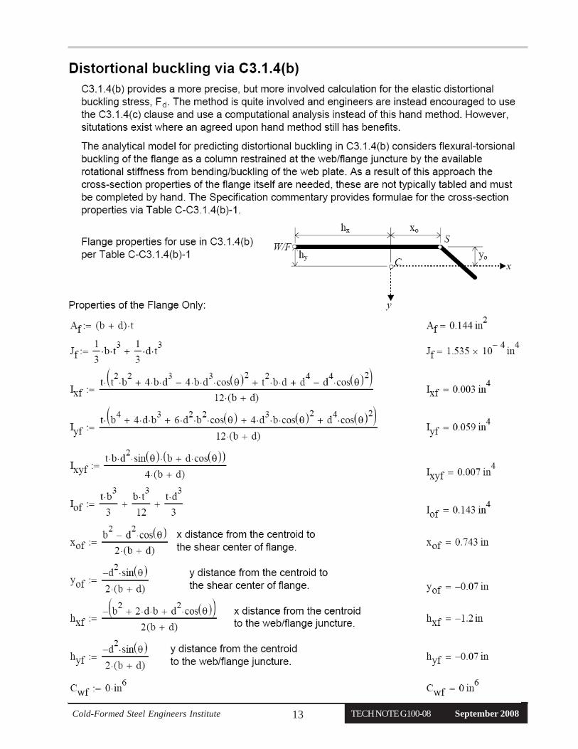
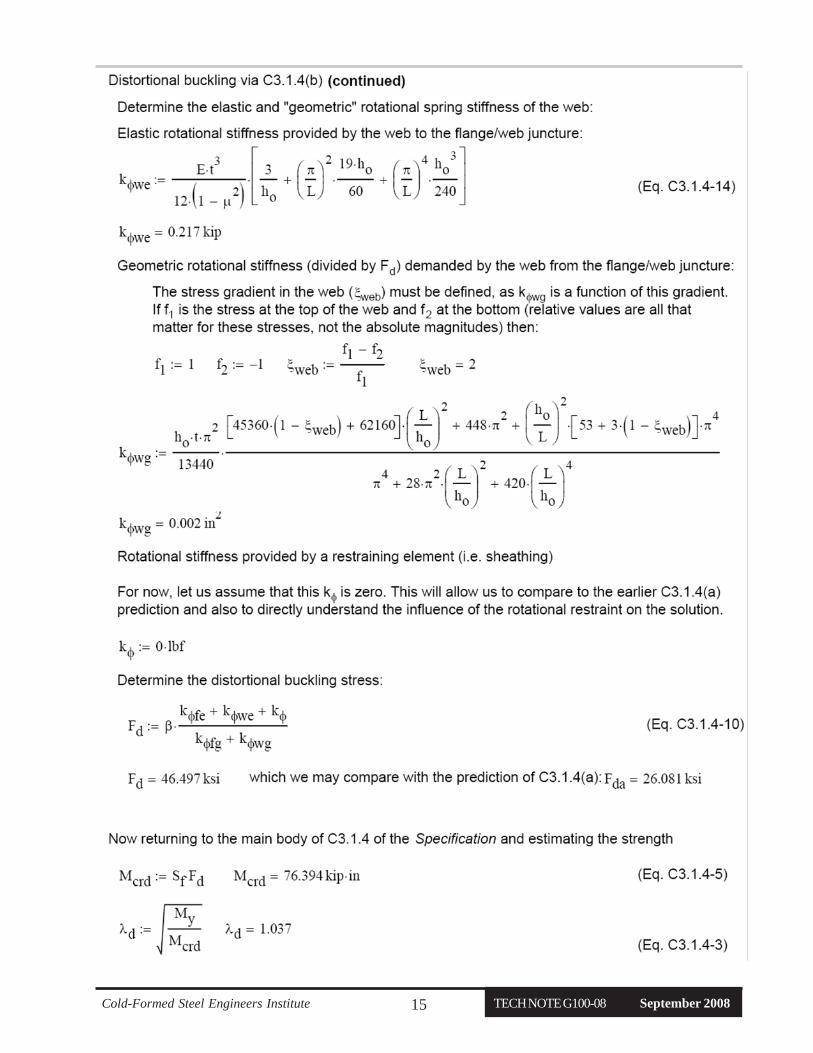
Cold-Formed Steel Engineers Institute TECH NOTE G100-08 September 200813

TECH NOTE G100-08 September 2008 Cold-Formed Steel Engineers Institute14
Cold-Formed Steel Engineers Institute TECH NOTE G100-08 September 200815

TECH NOTE G100-08 September 2008 Cold-Formed Steel Engineers Institute16

Cold-Formed Steel Engineers Institute TECH NOTE G100-08 September 200817
TECH NOTE G100-08 September 2008 Cold-Formed Steel Engineers Institute18

Cold-Formed Steel Engineers Institute TECH NOTE G100-08 September 200819

TECH NOTE G100-08 September 2008 Cold-Formed Steel Engineers Institute20

Cold-Formed Steel Engineers Institute TECH NOTE G100-08 September 200821

TECH NOTE G100-08 September 2008 Cold-Formed Steel Engineers Institute22
Primary Author of this Technical Note:Ben Schafer Ph.D., P.E.,Johns Hopkins University
Technical Review:This Technical Note was approved by the CFSEITechnical Review Committee in 2008. Rob Madsen,P.E., Devco Engineering, Inc., chairman.
This “Technical Note on Cold-Formed Steel Construction” is published by the Cold-Formed Steel Engineers Institute (“CFSEI”). Theinformation provided in this publication shall not constitute any representation or warranty, express or implied, on the part of CFSEIor any individual that the information is suitable for any general or specific purpose, and should not be used without consulting with aqualified engineer, architect, or building designer. ANY INDIVIDUAL OR ENTITY MAKING USE OF THE INFORMATIONPROVIDED IN THIS PUBLICATION ASSUMES ALL RISKS AND LIABILITIES ARISING OR RESULTING FROM SUCHUSE. CFSEI believes that the information contained within this publication is in conformance with prevailing engineering standards ofpractice. However, none of the information provided in this publication is intended to represent any official position of the CFSEI orto exclude the use and implementation of any other design or construction technique.
References
1. AISI-S100-07North American Specification for the Design of Cold-Formed Steel Structural Members. American Iron and Steel Institute,Washington, D.C., 2007.2. AISI-S210-07 North American Standard for Cold-Formed Steel Framing - Floor and Roof Systems Design. American Iron and SteelInstitute, Washington, D.C., 2007.3. AISI-S211-07 North American Standard for Cold-Formed Steel Framing - Wall Stud Design. American Iron and Steel Institute,Washington, D.C., 2007.4. Schafer, B.W., Sangree, R.H., Guan, Y. “Experiments on Rotational Restraint of Sheathing: Final Report”, American Iron and SteelInstitute - Committee on Framing Standards, Washington, D.C., 2007.5. Schafer, B.W., Sangree, R.H., Guan, Y. “Rotational restraint of distortional buckling in cold-formed steel framing systems.” InternationalConference on Thin-walled Structures. Brisbane, Australia, 18-20 June 2008.6. Schafer, B.W., Ádány, S. “Buckling analysis of cold-formed steel members using CUFSM: conventional and constrained finite stripmethods.” Proceedings of the Eighteenth International Specialty Conference on Cold-Formed Steel Structures, Orlando, FL. 39-54, 2006.CUFSM is available at www.ce.jhu.edu/bschafer/cufsm
Author InformationThe author of this Technical Note is B.W. Schafer, AssociateProfessor, Johns Hopkins University. Professor Schafer isthe author of the new distortional buckling provisions inAISI-S100. Professor Schafer serves on both the AISICommittee on Specifications and AISI Committee on FramingStandards. Professor Schafer is a past president of CFSEI.
Related Documents