DOCUMENT RESUME ED 272 694 CE 044 783 TITLE Apprentice Still Photographic Specialist (AFSC 23132). INSTITUTION Air Univ., Gunter AFS, Ala. Extension Course Inst. PUB DATE 79 NOTE 390p.; Supersedes ED 226 227. PUB TYPE Guides Classroom Use - Materials (For learner) (051) EDRS PRICE MF01/PC16 Plus Postage. DESCRIPTORS *Apprenticeships; Behavioral Objectives; Correspondence Study; Laboratory Procedures; Learning Activities; Military Personnel; Military Training; *Photographic Equipment; *Photographs; *Photography; Postsecondary Education; *Production Techniques; *Trade and Industrial Education IDENTIFIERS Air Force; Military Curriculum Materials ABSTRACT This four-volume student text is designed fow use by Air Force personnel enrolled in a self-study extension course for apprentice still photographic specialists. Covered in the indiviCual volumes are general subjects (career ladder progression, security, photographic safety, and photographic laboratory administration); still photographic fundamentals (existing and supplemental light sources, photographic exposure, sensitized black-and-white materials, photographic optics, and photographic filters); photographic camera assignments (principles of photographic composition, general and studio assignments, and reproduction photography); and photographic laboratory applications (black-and-white chemistry, film processing and finishing, printing, and finishing; principles of color photography; and quality control). Each volume in the set contains a series of lessons, exercises at the end of each lesson, a bibliography, and answers to the exercises. Volume review exercises are also included. (MN) *********************************************************************** Reproductions supplied by EDRS are the best that can be made from the original document. ***********************************************************************

Welcome message from author
This document is posted to help you gain knowledge. Please leave a comment to let me know what you think about it! Share it to your friends and learn new things together.
Transcript
DOCUMENT RESUME
ED 272 694 CE 044 783
TITLE Apprentice Still Photographic Specialist (AFSC23132).
INSTITUTION Air Univ., Gunter AFS, Ala. Extension Course Inst.PUB DATE 79NOTE 390p.; Supersedes ED 226 227.PUB TYPE Guides Classroom Use - Materials (For learner)
(051)
EDRS PRICE MF01/PC16 Plus Postage.DESCRIPTORS *Apprenticeships; Behavioral Objectives;
Correspondence Study; Laboratory Procedures; LearningActivities; Military Personnel; Military Training;*Photographic Equipment; *Photographs; *Photography;Postsecondary Education; *Production Techniques;*Trade and Industrial Education
IDENTIFIERS Air Force; Military Curriculum Materials
ABSTRACTThis four-volume student text is designed fow use by
Air Force personnel enrolled in a self-study extension course forapprentice still photographic specialists. Covered in the indiviCualvolumes are general subjects (career ladder progression, security,photographic safety, and photographic laboratory administration);still photographic fundamentals (existing and supplemental lightsources, photographic exposure, sensitized black-and-white materials,photographic optics, and photographic filters); photographic cameraassignments (principles of photographic composition, general andstudio assignments, and reproduction photography); and photographiclaboratory applications (black-and-white chemistry, film processingand finishing, printing, and finishing; principles of colorphotography; and quality control). Each volume in the set contains aseries of lessons, exercises at the end of each lesson, abibliography, and answers to the exercises. Volume review exercisesare also included. (MN)
***********************************************************************Reproductions supplied by EDRS are the best that can be made
from the original document.***********************************************************************
APPRENTICE STILL PHOTOGRAPHIC SPECIALIST
(AFSC 23132)
U S. DEPARTMENT OP EDUCATIONOhic f ducetional Research and linproverYfint
ED AT1ONAL RESOURCES INFORMATIONCENTER (ERICI
This deCurnent has been reerecluced asreceived liarn tra: Der Seri or ei'clit^i23?ic'caiginatng itMinor changes have bee' made to innaiovereprOduCtion Quality
Points of yiee. ei OPin.ons slated .^In'S dccumen! de not necessarily rePresent officialOER, Incisilq7n or poliCy
Extension Course Institute
Air University
BEST COPY AVAILAbLE
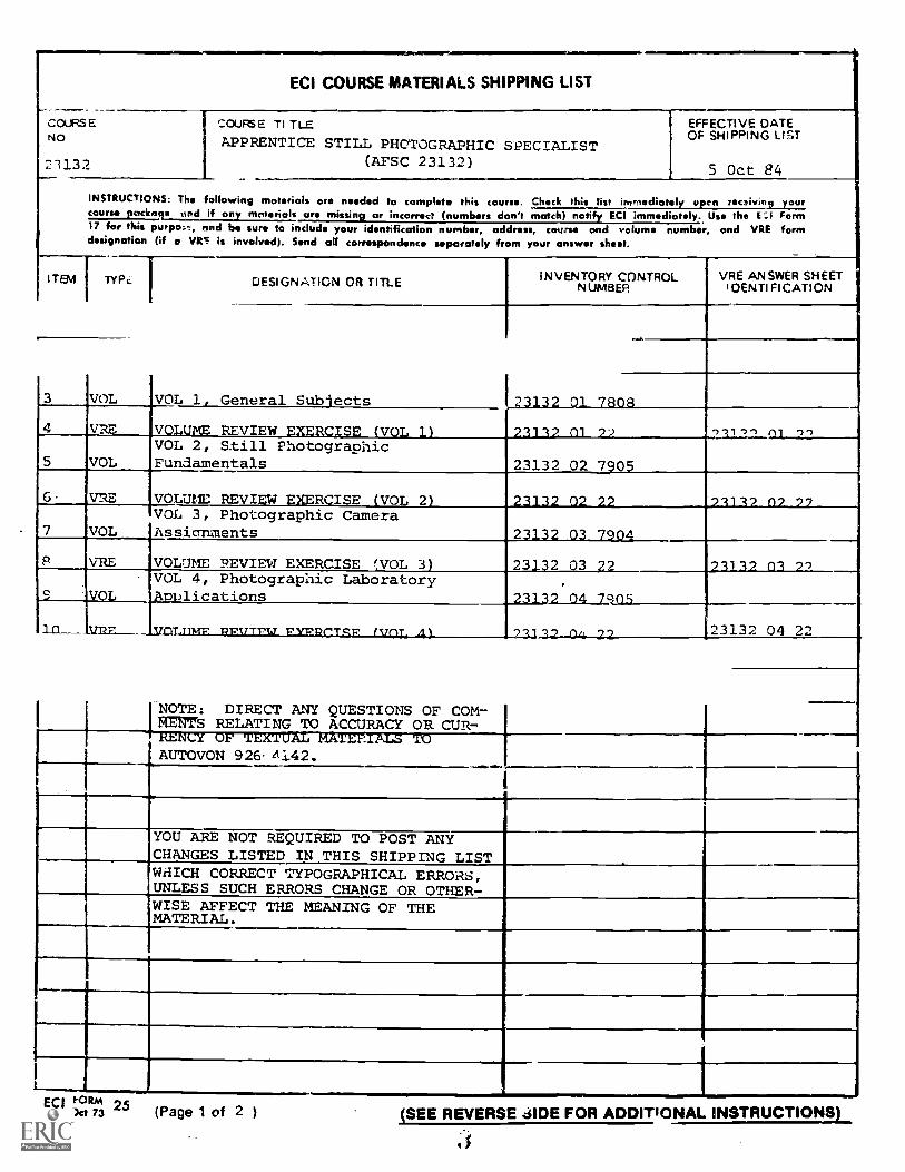
ECI COURSE MATERIALS SHIPPING LIST
COURSENO
21132
COUFGE T1 TLE
APPRENTICE STILL PHOTOGRAPHIC SPECIALIST(AFSC 23132)
EFFECTIVE DATEOF SHIPPING L/57
5 Oct 84
INSTRUCTIONS: The following materials are needeci ta complete this course. Chck this list immediately upen recsiving yourcourse pcknts und if any mciterials are missing or incorrect (numbers don't match) notify ECI immediately. Use the E:I Form17 for this purpost, and be sure to include your identification number, address, course and volume number, and VRE formdesignation (if a VRE h involved). Send all correspondence separately from your answer chest.
ITEM TYPz: 1 DESIGNATION OR TIME INVENTORY CONTROLNUMBER
VRE ANSWER SHEETIDENTI Fl CATI ON
VOL VOL 1, General Subiects II :II:
VRE V. i VIEW IS V
VOLVOL 2, Still PhotographicFundamentals 23132 02 710
7. VE VOLUME REVI A R ISE VO 2 I
VOLVOL 3, Photographic CameraAssianments 2 Il
VRE VOLUME REVIEW EXERCISE WOL 3J 23 2 3 2 I 'Y')VOL 4, Photographic LaboratoryA pjcations
.
1 n' , 242.2-4W-2.2 23132 04 22.,
[NOTE: DIRECT ANY QUESTIONS OF COM-MENTS RELATING TO ACCURACY OR CUR7RENLY OF TEXTUAZ MATErTALS TOAUTOVON 926 1142.
.......-
I
YOU ARE NOT REQUIRED TO POST ANYCHANGES LISTED IN THIS SHIPPING LISTWHICH CORRECT TYPOGRAPHICAL ERRORS,UNLESS SUCH ERRORS CHANGE OR OTHER-WISE AFFECT THE MEANING OF THEMATERIAL.
ECI ":)11"4 25oet 73 (Page 1 of 2 ) (SEE REVERSE JIDE FOR ADDITIONAL INSTRUCTIONS)
.$
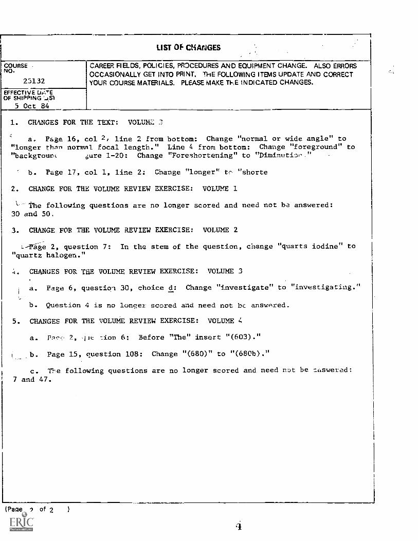
LIST Of CHAFJGES
COURSENO.
23132
EFFECTIVE UAYEOF SHIPPING
5 Oct 84
CAREER FIELDS, POLICIES, PR:DCEDURES AND EQUIPMENT CHANGE. ALSO ERRORSOCCASIONALLY GET INTO PRINT. THE FOLLOWING ITEMS UPDATE AND CORRECTYOUR COURSE MATERIALS. PLEASE MAKE ThE tNDICATED CHANGES.
1. CHANGES FOR THE TEXT: VOLUK
a Page 16, col 2, line 2 from bottom: Change "normal or wide angle" to"longer thnn normnl focal length." Line 4 from bottom: Change "foreground" to"backgrount .12.re 1-20: Change "Foreshortening" to "Diminutior."
b. Page 17, col 1, line 2: Change "longer" tr- "shorte
2. CHANGE FOR THE VOLUME REVIEW EXERCISE: VOLUME 1
`---The following questions are no longer scored and need not ba answered:30 and 50.
3. CHANGE FOR THE VOLUME REVIEW EXERCISE: VOLUME 2
L-Tage 2, question 7: In the stem of the question, change "quarts iodine" to"quartz halogen."
4. CHANGES FOR THE VOLUME REVIEW EXERCISE: VOLUME 3
a. Page 6, questioq 30, choice d: Change "investigate" to "investigating."
b. Question 4 is no longer scored and need not bc ansvmred.
5. CHANGES FOR THE VOLUME REVIEW EXERCISE: VOLUME 4
a. 2, jt :ion 6: Before "The" insert "(603)."
b. Page 15, question 108: Change "(680)" to "(680b)."
c. The following questions are no longer scored and need not be aaswered:7 and 47.
(Page 2 of 2
23132 01 7808
CDC 23132
APPRENTICE STILL PHOTOGRAPHIC
SPECIALIST
(AFSC 23132)
Volume 1
General Subjects
Extension Course InstituteAir University
It)
Prepared byMSgt Curtis Mayne
andMSgt Jay Perry
3430th Technical Training GroupUSAF School of Applied Aerospace Sciences (ATC)
Lowry AFB, Colorado 80230
Reviewed byCarole C. Jones, Education Specialist
Extension Course Institute (AU)Gunter AFS, Alabama 36118
PREPARED BY3430TH TECHNICAL TRAINING GROUP
USAF 'CHOOL OF APPLIED AEROSPACE SCIENCES (ATC)LOWRY AIR FORCE BASE. COLORADO
CXTFNSION COURSE INSTITUTE, GUNTER AIR FORCE STATION, ALABAMA
THIS PUBLICATION HAS BEEN REVIEWED AND APPROVED SY COMPETENT PERSONNEL OF THE PREPARING COMMANDIN ACCORDANCE WITH CURRENT DIRECTIVES ON DOCTRINE, POLICY, ESSENTIAUTY, PROPRIETY, AND QUALITY.
6
PrefaceTH!S CAREER Development Course is designed to help you qualify for the dutiesand responsibilities of an Air Force Apprentice Still Photographic Specialist, AFSC23 /32. The course consists of four volumes: this volume contains information oncareer ladder progression, security, photographic safety, and photographic laboratoryadministration; Volume 2 deals with photographic fundamentals; Volume 3 covers thedifferent types of photographic camera assignments; and Volume 4, coversphotographic duties within the laboratoiy.
If you have questions on the accuracy or currency of the subject matter of the text, orrecommendations for its improvement, send them to the 3430th Technical TrainingGroup irTMZS, Lowry AFB CO 80230. Questions requiring immediate resolutionmay be directed to the course authors at AUTOVON 926-4142 between 0800-1600 hrs( MST) Monday through Friday. NOTE: Do not use the suggestion program to submitcorrections for typographical or other errors.
If you have questions on course enrollment or administration, or any of ECI'sinstructional aids (Your Key to Career Development, Behavioral Objective Exercises,Volume Review Exercise, and Cc se Examination), consult your education officer,training officer, or NCO. as appropriate. If this agent can't answer your questions, sendthem to ECI, Gunter AFS AL 36118, preferably on ECI Form 17, Student Request forAssistance.
This volume is valued at 6 hours (2 points).
Material in this volume is technically accurate, adequate, and current as of May1977.
ill

Contents
Chapter
Preface
Page
iii
1 Career Laddf Progression 1
2 Security 8
3 Photographic Safety 14
4 Photographic Laboratory Administration 18
Bibliography)._
35
Answers fo?' Exercises 37
iv
CHAPTER 1-4.1111,
NOTE: In thls volume, the subject matter la developed by a series of student-cern .
objectives. Each of these carries a three-diglt number and is in boldface type. Each sets alearning goal for you. The text that fr. Ns the oi...,:ctive gives you the information you need toreach that goal. Th0 aollovt....g the information glve you a check on your achievement.When you comr see whether your answers match those in the back of this volume. Ifyour response to an exercise Is Incorrect, review the objective and its text.
Career Ladder Progression
CONGRATULATIONS on your assignment as anaudiovisual helper in the still photographic job specialty.As you begin studying this career development course(CDC), you are entering a highly professional andsatisfying career field. As a photographer, you will bepermitted and even encouraged to express yourself inyour work. The rewards of your efforts in photographyare the recognition you receive when your work is put ondisplay on office walls, printed in base and localnewspapers, or possibly in service-wide or nationalpublications. Very few Air Force careers offer this specialtype of recognition for individual job accomplishment.
In this chapter, you should learn several of the factorsthat affect your progression in the audiovisual careerfield. As you begin your study of this CDC, keep in mindthe following quote from AFR 35-1, Military PersonnelClassification Policy:
Individual Responsibilities. An individual's career progression,including promotion in the Air Force, is directly related to theefforts expended by the officer or airman to attain and maintainqualification in his specialty. Therefore, attaining and maintaininathis qualification are primarily !he res,potkiNliry of irojvidu,t.Classroom, se,-clar **.'" , koalas tokmbase of dee,-^-' 416 czertinzates from military and
inznitucions, including programs of theCc, :ge of the Air Force (CCAF) which incorporatespcciahy training with academic education are available throughBase Education Service Centers. Each officer and airman isencouraged to avail himself of every opportunity for increasing histechnical qualifications and enhancing his professional and militaryknowledge.
In view of the preceding, you see that theaccomplishment of this CDC is your responsibility towadyour career progression.
1-1. Airman Classification System
Let's begin our discussion with why you were assignedto the audiovisual career field. Perhaps you had a choiceof jobs and this was your first choice. But if you are notdoing exactly what you wanted, there is a reason for it.The needs of the Air Force come first.
.11.11111.
001. Define the Military Classification System andstate what the components of an AFSC mean.
The audiovisual career field is an integral part of theMilitary Classification System. This classification systemidentifies the duties required for each position essential inaccomplishing the mission of the Air Force and I, xuratelyidentifies tile abilities of individuals in relation to thequalifications required to perform in these positions.Positions are grouped according to required commonknowledge, skills, and other abilities into Air ForceSpecialties (AFSs) with each AFS having a specialtydescription, title, and number known as an AFSC (AirForce specialty code). You are presently striving forAFSC 23132.
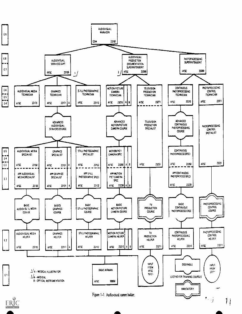
Each specialty within the career field is identified by anAir Force specialty code. Each AFSC is identified by anAir Force specialty code. Each AFSC is identified by afive-digit number. The first two digits iden0field. The third number, combined with vo,o,identifies the ..-areer field sutid:vision. Skill , shownri On fourth digit. There are five different si. level: I
helper, 3 semi-skilled (ap entice); 5 skilled(journeyman); 7 advanced (st isor, technician); and 9superintendent. The fifth digit, c.ombined with the otherfour, identifies the specific Air Force specialty. The23132 AFSC you are now working for breaks as follows:
23 Career Field: Audio Visual231 Career Field Subdivision: Photography
2313 Skill Level: Semiskilled (Apprentice)
23132 Specific Air Force Specialty: Apprentice
Still Photographic Specialist
Exercise (001):I . Complete the following statements by
missing word(s):mg the
a. The classification system identifies duties of a joband the of individuals in relation to thoseduties.
1 3
ES
(
0111,
E
E S
0.4arw
01,
1
E 9
AUDIOVISUAL
MANAGER
AUDIOVISUAL
SERVICES SUPT
AFSC 23199 LI
AUDIOVISUAL
PRODUCTION
DOCUMENTATION
SUPERINTENDENT
AFSC 23299
PHOTOPROCESSING
SUPERINTENDENT
AFSC 23399
AUDIOVISUAL MEDIA
TECHNICIAN
23170
GRAPHICS
TECHNICIAN
$; ILL PHOTOGRAPHIC
TECHNICIAN
MOTION PICTURE
CAMERA
TECHNICIAN
AFSC 23171 A AFSC 23172 AFSc 23170 A B
TELEVISION
PRODL1CTION
TECHNICIAN
AFSC 71271---
ADVANCED
AUDIOVISUAL
SERVICES COURSE
ADVANCED
MOTION PICTURE
CAMERA COURSE
AUDIOVISUAL MEDIA
SPECIAL IS1
GRAPHICS
SPECIALIST
STILL PHOTOGRAPHIC
SPECIALIST
MOTION PICT
CAMERA SPEC
AFSC 23150
ili . M., IIM .0
APP AUDIOVISUAL
MEDIA SPECIALIST
AFSC
23152 AFSC 23250 A B
TELEVISION
PRODUCTION
SPECIALIST
AFSc 23231
CONTINUOUS PHOTUPROCESSING
PHOTOPROCESSING CONTROL
TECHNICIAN TECHNICIAN
AFSC 23370 AFSC 23371
ADVANCED
coNTINUOUS
PHOTOPROCESSING
COURSE
23130
APP GRAPHICS
SPECIALIST
APP STILL
PHOTOGRAPHIC SPEC!
AFSC 23131 A 23132
APP MOTION
PICT CAMERA
SPEC
osC 23230 A
CONTINUOUS
PHOTOPROCESSSPECI
AFSC 23350
APP CONTINUOUS
PHOTOPROCESS SPEC'
AFSC 23330
BASIC
AUDIOVISL',L MEDIA
COLI,1A
BASICS
GRAPHICS
COURSE
BA.SIC
STILL PHOTOGRAPHIC
COURSE
BASIC
MOTION PICTURE
CAMERA COURSE
AUDIOVISUAL MEDIA
HELPER
GRA HICS
HEL ER
STILL PHOTOGRAPHIC
HELPER
MOTION PIC URE
CAMERA HELPER
23110 AFSC 73111 23112 AFSC 23210
Tv
PRODUCTION
COURSE
rAFSC 23211
TV
PRODUCTION
HELPER
BASIC
CONTINUOUS
PHOTOPROCESS CASE
CONTINUOUS
PHOTOPROCESSING
HELPER
AFSC 23310
PHOTOPROCESSING
CONTROL
SPECIALIST
AFSC 23331
PHOTOPROCESSING
CONTROL
COURSE
PHOTOPROCESSING
CONTROL
HELPER
AFSC 27311
- MEDICAL ILLUSTRATOR
- MEDICAL
B - OPTICAL INSTRUMENTATION
BASIC AIRMAN
INPUT
FROM
AF SC
79151
DESIRABLE
LEGEND FOR TRAINING COURSES
Figure 1-1, Audiovisual career ladder,
4 4 7
b. Each specialty within a career field is identifiedby a digit number called a (an)
c. There are different skill levels; they a.-e:
002. Given a list of upgrade requirements, select thosewhich are mandatory for award of AFSC 23132.
How Can You Earn the 3 Level? One way to achievethe apprentice level is to pass the AFSC 23132apprentice knowledge test (A KT). This test is given toairmen who have had previous photographicexperience. Upon passing the test, they can be assignedas a 3 level. Another way is to graduate from the BasicStill Photographic Course taught at Lowry Air ForceBase, Colorado. Finally, you can achieve the 3 level theway you are doing it, through upgrade training whileyou are working on the job after being assigned directlyfrom basic training.
NOTE: Each A FSC may limit the manner in whichthe 3 level may be earned. Certain A FSCs may requirea mandatory basic course. Others may not offer anyschool and require OJT training.
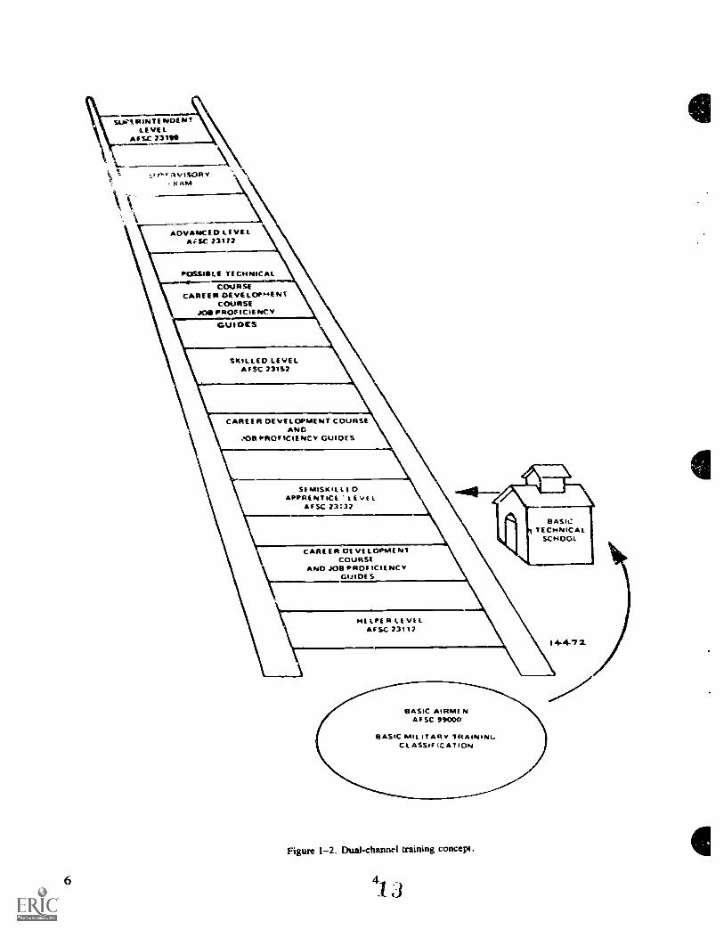
Upgrade training. Upgrade training was developedto qualify Air Force personnel at the next higher levelof job proficiency in the shortest possible time.Currently, the Air Force is using the dual-channelconcept for upgrade training. As the name suggests,there are two parallel segments involved in thetraining. These segments are job proficiency and jobknowledge. Job proficiency is accomplished by on-the-job training (OJT) and job knowledge is obtainedthrough completion of career development courses(CDCs).
On-the-job training provides you with practicaiexperience in performing the duties required by thespecialty. This performance is accomplished under theclose supervision of a qualified trainer. It allows you todemonstrate your ability to perform under actualworking conditions.
The career development course you are taking is aself-instructional publication. It provides informationon the concepts, principles, and basic knowledgesrequired by your specialty. This information isprovided to the level required by the sptcialty trainingstandard (STS) developed for your speciaity. Figure 1-2 shows the steps in,. olved in the dual-channel trainingprogram.
NOTE: To attain your 3 level, in addition tocompleting this CDC and meeting your OJTrequirements, you must have your supervisor'sapproval and have completed your training within 12months.
Specialty qualifications. Changes or awards of anAFSC are based on standards from AFR 39-1,
3
Airman Classification Regulation, and informationfrom AFR 35-1. These standards are prescribed inparagraph 3 (Specialty Qualifications) of eachspecialty description. There are mandatory anddesirable requirements in "knowledge," "education,""experience," "training," and "other." Mandatoryrequirements are minimums for the award of anA FSC. Desirable requirements aid in your ability towork in your AFSC. The following is an extract fromthe specialty description.
3. Specialty Qualifications
a. Knowledge:
(I) Knowledge of photographic theory. technology, andprocesses. including mechanics of camera. laboratory, andallied equipment; photochemistry and use of sensiti7edmaterials and filters: photographic layout and illustrations;pictorial aesthetics and composition; photographic methods ofrecording and displaying information: photographic laboratorytechniques; and lenses is mandatory. Possession of mandatoryknowledge will be determined in accordance with AFR 35 I.
(2) Knc-4-1ecige of photojournalism; picture editing;technical and documentary photography; and procedures Iormaking negatives for offset and gravure printing is desirable.
h. Education: Completion of high school with courses inphotogiaphy and chemistry is desirable.
c. Experience: Exptnce in functioas such as stillphotlgraphy and photofinishing is mandatory.
d. Training: Completion of a basic still photographic courseis desirable.
Other:
(1) A minimum aptitude level of z,eneral 40 is mandatory.
(2) Normal color vision as defined in AFR 160 43 or ascore of 50 using VTA CTT is mandatory.
You met the mandatory requirements of item 3ebefore you were assigned to the still photographicspecialty of the audiovisual career field.
Exercise (002):
1. From the following list of upgrade requirements,select those which are mandatory to attain the 3level when you have been given a direct dutyassignment.
a. Completion of high school.b. Knowledge of photochernistry.c. Completion of the apprentice level CDC.d. Approval of your supervisor.e. Knowledge of picture editing.
093. Associate military grades w ith the proper skilllevels.
Career Progression. Once you have completed yourevel, you immediately begin working toward your 5
level. Promotion to the grade of senior airman ispossible only if you hold the 3 level, and to staffsergeant if you have achieved the 5 level. Generally
SUg1RINTE NOE NTLEVEL
*PSC 231110
r."."RvISORYXAM
ADVANCED LEVELAVEC 73172
POSSIBLE TECHNICAL
COURSECAREER DEVELOP*TENT
COURSEJOB PROF ICIE NC Y
GUIDCS
SKILLED LEVELAFSC 73152
CAREER DEVELOPMENT COURSEANC
!OR PROFICIENCY GUIDES
CAREER DE VELOPMENTCOURSE
ND JOB PRDF ICIE NC YGUIDES
HELPER LEVELAFSC 73112
14472
BASIC AIRME NAF SC 99000
BASIC miL IT AR Y TRAININL,CL ASSIF cc AT ION
Figure 1-2. Dual-channel training concept.
si
speakintl, acquisition of AFSC 23152 is based ongreater proficiency and understanding of 23132subjects and limited supeivisory ftmctions.
You must continue training into AFSC 23172 toreach technical or master se:geant. At this level,airmen are expected to reach the highest required levelof technical knowiedge in their specialty. The greatestdifferences between AFSCs 23152 and 23172 lie in theareas of supervision anci admir;istration.,
AFSC 23192 is awarded to masterageintS froM'AFSCs 23170, 23171, or 23172. The'se NCOs havepassed ci:mprehensive tests in management r.roceduresair' have been selected by board action. As this skilllevel is the culmination of years of dedicated service inthe audiovisual care,:r field, competition for it is verykeen.
Exercise (003):
I. Match the grade listed Ir. column A with theappropriate skill level in column B.
( ',a/mut .1
I I: t,
Column B
a. 231522 I. 5 b. 23172
2 c. 231324 I X d. 231925 I: 4 c. 2312
1-2. Duties of AFSs 23132/52/72You were awarded AFSC 23112 upon completion of
basic training. Now you are in upgrade training to the3-level A FSC and, although you hold a I level, you areperforming 3-level duties. Soon, upon award of your 3level, you will perform 5-level duties, and then later on,you will assume 7- arid 9-level responsibilities.
004. Identify the duties performed at the 3, 5, or 7level.
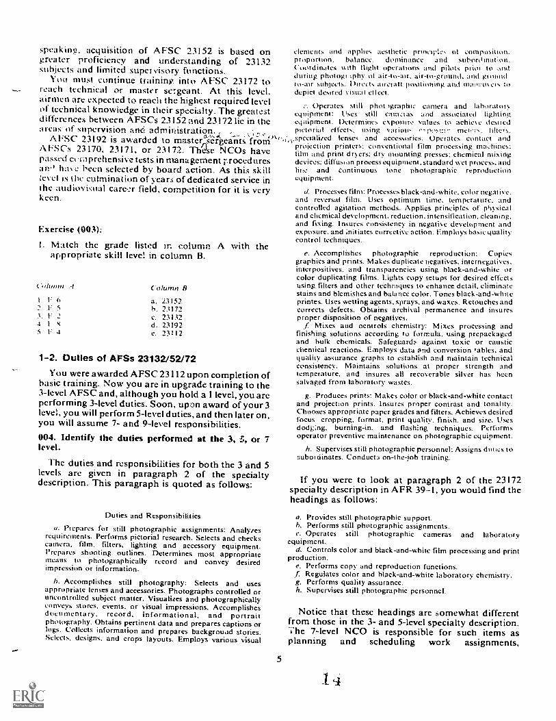
The duties and responsibilities for both the 3 and 5levels are given in paragraph 2 of the specialtydescription. This paragraph is quoted as follows:
Duties and Responsibilities
a. Prepares for still photographic assignments: Analyzesrequirements. Performs pictorial research. Selects and checkscamera, film, filters, lighting and accessory equipment.Prepares shooting outlines. Determines most appropriatemeans to photographically record and convey desiredimpression or information.
b. Accomplishes still photography: Selects and usesappropriate lenses and accessories. Photographs controlled oruncontrolled subject matter. Visualizes and photographicallyconveys stores, events, or visual impressions. Accomplishesdocumentary, record, informational, and portraitphotography. Obtains pertinent data and prepares captions orlogs. Collects information and prepares backgroudd stories.Selects, designs, and crops layouts. Employs various visual
on,
elements and applies aesthetic principles ol composition.proportion. balance. dominance :I nd subordination.Coordinates %vith flight operations and pilots prim to :Indduring photogriphy of air-to-air. air-to-ground. and gi mind-to-air subjects. Du eels ancratt positioning and mit:r..to et. todepict desired visual etlect.
Operates still photographic camera and lahoratorvequipnwnt: Uses still Ca m,:ras and associated lightingequipment. Determines exposure values to achie% e &sitedpictorial effects, using various , post!! ructci.s, filters,
,,.opecialited lenses and accessories. Operates contact andprojection printers: conventional film processing machines:film and print dryers: dry mounting presses: chemical mixingdevices: diffusion process equipment ,standard wet process. andline and continuous tone photographic reproductionequipment.
d. Processes film: Processes bbck-and-white. color negative.and reversal film. Uses optimum time, temperature, andcontrolled agitation methods. Applies principles of physicaland chemical development. reduction, intensification. ckaning.and fixing. Insures consistency in negative development andexposure. and initiates corrective action. Employs basic qualitycontrol techniques.
e. Accomplishes photographic reproduction: Copiesgraphics and prints. Makes duplicate negatives. internegatives.interpositives. and transparencies using black-and-white orcolor duphcating films. Lights copy setups for desired effectsusing filters and other techniques to enhance detail, eliminatestains and blemishes and balance color. Tones black-a nd-whneprintes. Uses wetting agents. sprays, and waxes. Retouches andcorrects defects. Obtains archival permanence and insuresproper disposition of negatives.
Mixes and ocntrols chemistry: Mixes processing andfinishing solutions according to formula, using prepackagedand bulk chemicals. Safeguards against toxic or causticchemical reactions. Employs data and conversion tables, andquality assurance graphs to establish and maintain technicalconsistency. Maintains solutions at proper strength andtemperature, and insures all recoverable silver has beensalvaged from laboratory wastes.
g. Produces prints: Makes color or black-and-white contactand projection prints. Insures proper contrast and tonality.Chooses appropriate paper grades and filters. Achieves desiredfocus cropping. format, print quality, finish, and size. Usesdodging. burning-in, and flashing techniques. Performsoperator preventive maintenance on photographic equipment.
h. Supervises still photographic personnel: Assigns duties tosubotdinates. Conduct:i on-the-job training.
5
If you were to look at paragraph 2 of the 23172specialty description in AFR 39-1, you would find theheadings as follows:
a. Provides still photographic support.h. Performs still photographic assignments.e. Operates still photographic cameras and laboratory
equipment.d. Controls color and black-and-white film processing and print
production.e. Performs copy and reproduction functions..1 Regulates color and black-and-white laboratory chemistry.g. Performs quality assurance.h. Supervises still photographic personnel.
Notice that these headings are somewhat differentfrom those in the 3- and 5-level specialty description.ale 7-level NCO is responsible for such items asplanning and scheduling work assignments,
establishing work methods, production controls, andperformance standards; insuring availability ofmaintenance equipment, tools, and spare parts; andestablishing work priorities. He has to be moreproficient in all the technical areas and is more heavilyinvolved in supervision and task analysis than his 3-and 5-level subordinates.
Exercises (004):
I. At which skill level arc you most likely to be askedto clean a processing machine?
2. At which skill level would you most likely beconcerned with conducting 3-level OJT?
3. At which skill level would you most likely beconcerned with planning and scheduling workassignments?
1-3. TrainingThe Air Force has all types of training available. By
the time you have reached this point in your career, youmay have experienced at least two types of training.First, you were given basic military training. Now, youare studying this CDC as part of your on-the-jobtraining. You will continue with this type of trainingthrough your 5 and 7 levels. You may also be eligiblefor special training for certain parts of your job.
005. List the types of special training that are availableand identify the contents of AFM 50-5.
Types of Training. The field training program of theAir Force is designed to conduct transition training toqualify skilled personnel on new or different types ofequipment associated with their AFSCs. It conductsfamiliarization training for those who already have afundamental technical knowledge but who need tolearn the composition and functions of a specificsystem. Proficiency training is given to maintain a',iven skill level.
Special training is given to qualify skilled airmenwho are retraining into a different career field or careerladder. Another type of special training is contractspecial training. This type of training, often referred toas factory training, is formal training conducted undercontract with civilian industrial or educationalinstitutions. The training is conducted either at thecontractor's location or at an Air Force base. Contractspecial training is usually used when new weapon,command and control, or support systems aredeveloped. Often, this type of training is used todevelop an initial cadre of trained personnel until ATCcan institute a training program.
Still another type of special tt aining is ATC SpecialResident Train This training is formal training of aone-time or h. -lied nature conducted by ATCinstructors at an Air Force base. This type of specialtraining is frequently used as a followup to contractspecial training.
Training Information Sources. If you need to findout what training is available, you should consultA FM 50-5. USA F Formal Schools Catalog. This two-volume manual lists all of the formal training coursesconducted by the Air Force.
Let's see what information AFM 50-5 contains andhow it can lte;p ,ou. Volume 1 of AFM 50.-5 is dividedinto 13 chapters. Chapter 1 coitzains generalinformation and instruc:ions. Some of the itemscovered are general prerequisites for training. if youwish to go to school, you should consult Chapter 1 tofind out whether you are eligible. For example, thelength of a course determines the length of time thatyou must have remaining on your current enlistment inorder to qualify for the tvaining. This Lhapter alsocontains general application procedures and reporlinAinstructions.
Chapters 2 through 13 contain information oncourses monitored by major commands. rIn Chapter 3,informatiort is available on Air Training Commandcourses.
This chapter starts with general information onATC courses. It contains an explanation of the :ATCcourse numbering system. It also contains reportinginstructions for each base conducting ATC monitoredcourses. These instructions tell the earliest and latestreporting time and ind3cate to which building youreport. Voaime 2 of AFM 50-5 lists all courses bynumber. Each individual announcement contains thecourse numbei-, title, length, a brief description,prerequisites, and necessary security clearance.
The following is the course announcement for thephotojournalism course taught at Lowry AFB. Wehave included it to show you part of what is containedin AFM 50-5.
6
G3AZR23I52 00IStill Photojournalistic Techniques PDSCode UOZDOD400Lowry/ 6wkSep 76The photojournalistic process with emphasis on thephotojournalistic sequence, information acquisitiontechniques, elements of style in writing, communication withpeople, legal and ethical aspects; tools of :he trade, state of theart, with instruction on use of various processing techniques,with exercises to develop photojournalist's awareness of peoplepictures; job-oriented workshop emphasizing personalityfeature, groups, spot news, publicity, editorial sports, picturestory and layout.
Prerequisites: Amn: Min grade of Sgt E-4 with one yearretainability; A FSC 5 or 7 ievel 231X2 or 791X0; must be fullyqualified in actual camera operation; experience in Info Officephotography desired. Civ: Equivalent qualifications. Off:Equivalent qualification, A FSC 23XX or 79XX. Personnel areencouraged to bring personal camera equipment to course. Onecopy of student's orders to arrive LITC/TTMZS, Lowry AFB,CO 80230, 10 days prior to class start date.
Quotas controlled by ATC/ TIPP.
15
From this example you can tell that nearlyeverything you want to know about thephotojournalism course (length. contems. grade.A FSC) is included in .A.FM 50 5.
f!rcises (005):
I. List three types of specialized training.
2. What types of information can you find 1.1 AFM50 5?
1-4. USAF G;oduate Eveitlatton ProgramSince neErly everything that is accomplished must be
tested or evaluateo, you are really no different. Thegraduate of Air Force training must be evaluated to seeif the schools ate producing 1.1n acceptable product.The next portion of this chapter deals with how the AirForce evaluates the graduates of its schools.006. I.ist three methods of field evaluation and fourfactors that can be determined through fieldevaluation.
Purpose. AFR 50-38, Field Evaluation of FormalSchool Graduates, establishes the requirement for aprogram to evaluate the graduates of Air Force formalschools. The program is a maior aid in the qualitycontrol of both formal and career developmentcourses. You may be asked to participate in theevaluation program after you fin:sh this CDC. But ifyou are not, you should remember that some graduateswill be asked, and that this evaluation will help the AirForce to achieve its purpose.
7
Methods. There are four methods us.:d to getinformation from the graduates:
Field evaluation visit. I n this type of evilua lion. thegraduate anc! ,...upervisor are interviewed by a tr:tiningexpert. The interview is usually held at the grAuate'splace of work. The visit is within six months after thegraduate has been assigned.
Direct correspondence questionnaire. AquesConnaire is mailed directly to the graduate and hissupervisor. Again this is done within six months aftergraduation. This method is obviously cheaper, andmor gractImes ccin be interviewed in a given time. Thismethod is the one yoo are most likely to be involved in.If you are chosen, you will get a questionnaire whenyou take the course examination.
Job performance evaluations.. Because of the costinvolved in th:- type of evaluation, it is seldom useri
AF Form 1284, Training Quality Report. This i.,form that the immediate supervisor fills Gilt if: thegraduate does not meet the required proficiency levels;the graduate is not required to do the duties of the SFS,or the STS code levels exceed the requirements of theAFSC.
Factors To Determine. All of the methe.d.; used togather information are designed to detel mine fivespecific factors.
a. The ability of the graduates to perform theirduties as ll as they are required to.
b. How much or how often the graduates use theirnew skills.
c. How well the graduates rerry:mber what they weretaught.
d. Whether the STS or school needs to be changed.e. Whether more evaluation is needed in specific
areas of the career field.se (006):
I. List three methods of field evaluation and fourfactors that can be determined through fieldevaluation.
CHAPTER 2
Secu rity
FROM TIME TO TIME, most photo labs arerequired to reproduce classified material for variousAir Forci agencies. As a still photographic technician,you are exposed to this kind of information as a part ofyour daily job. As a member of the Air Forcc, you aresubject to regulations that require you to take everypossitA action to insure the security of classifiedinformation.
Depar tment of Defense Regulation 5200.1-R,Information Security Progran: Regulationthe primepurpose of this regulation is to insure that officialinformation of the Department of Defense relating toNational security is protected, but only to the extentand tor such periods as is necessary. The regulationestablishes the basis for identification of informationto be protected; prescribes a progressive system forclassification, downgrading, and declassification;prescribes safeguarding policies and procedures to befollowed; and establishes a moaitoring system toinsure the effectiveness of the Information SecurityPi ogram throughout the Department of Defense.
In the Air Force, A FR 205-1, Information SecurityProgram, supplements the DOD InformationProgram Regulation (DOD ISPR 5200.1-R)governing the classification, downgrading,declassification, and safeguarding of classifiedinformation. It is applicable to all Air Force activities,including the Reserve components. The DOD ISPRestablishes standard DOD policies on the subjectmatter for all of the DOD components. This regulationamplifies those policies for use within the Air Forceand provides procedural details where appropriate.For this reason, neither the DOD ISPR nor thisregulation should be used without reference tocorresponding guidance contained in the other.
Air Force Regulation 205-1 is quite specificconcerning the individual's responsibility forcontrolling access to classified information. However,both regulations make it clear that each person whoseduties require him to have access to classifiedinformation must understand the purpose andprinciples of the information security program andassume responsibility for protecting all classifiedinformation he knows or possesses.
AFR 205-1 specifies what information is classified,who classifies it, and how the classification may bedowngraded or removed. It also sets forth procedures
for transmission, storage, receipting, and dest. ictionof classified material. If you are ever in doubt as to howto deal with a situation concerning classifiedinformation, use both i*f!gulations as guides for makingdecisions on what action to take.
This part of the text will help you to understand thetypes of information that may be of intelligence valueto unauthorized persons. It identifies the officialdesignations for classified defense information andspells out procedtires for insuring the safe transmittalof this information. It also stresses the possibilities forcommitting security violations during voicecommunications and the precautions to take to avoidthese pitfalls.
2-1. Types of Official InformationAny Air Force or Government information that you
may come in contact with is official information.Official information is any information owned by,produced by, or controlled by the United StatesGovernment. This CDC is, therefore, consideredofficial information.007. Given a list of different types of officialinformation state which information would heconsidered classified, unclassified, For Official UseOnly, or unclassified but of possible intelligence value.
Official information is divided into two broadcategories: classified and unclassified information.Classified defense information is official information,the safeguarding of which is necessary to preventunauthorized disclosure in the interest of nationaldefense and which is classified for such purposes by anappropriate classifying authority. For example,photographs (a form of information) of nuclearweapon experiments are classified information.Classified information is given only to a person whoseofficial duties require a need-to-know, who has beengiven the appropriate security clearance, and who hasthe proper identification. Unclassified information isofficial information which does not require theapplication of security safeguards, but the disclosure ofwhich may be subject to control for other reasons. Forexample, the orders assigning you to your first baseafter initial military training were unclassified.
Some official information, although unclassified,requires protection in the public interest. This
8
information is labeled "For Official Use Only" and iswithheld from widespread distribution to the public.You should not volunteer such information. Forexample, information in your personn.1 records islabeled "For Official Use Only."
Another subcategory of unclassified information isunclassified official information which is of possibleintelligence value. Unclassified information which,when zissoeiated with other unclassified information,reveals an insight into or the specifics of classifiedplans, programs, operations, or activities becomes ofpossible intelligence value. For example, when youknow a certain number of F-4s are on the runway, thisinformation is unclassified. However, when you learnthat they are armed with a certain type ofweapon, yougain an insight into a classified plan. If you also learnedthat they were to be refueled in flight by a specificrefueling squadron, you would have more informationwhich you could put together and gain a further insightinto a classified plan. Although none of these items bythemselves may be classified, the information gaineddefinitely has intelligence N al u e.
It is easy to see why all classified defense informationis of intelligence value and should not be revealed toanyone unless he is authorized to receive it. One of thebiggest problems is that people cannot tell thedifference between unclassified information andunclassified information of possible intelligence value.If you have any doubts. KEEP QUIET.Exercise (007):
I. State whether each of the following pieces ofinformation would be labeled "Classified,-"Unclassified," "For Official Use Only, or"Unclassified but of possible intelligence value."
a. Diagrams on a nuclear bomb *stem.b. Base movie schedule.c. "US Fighting Man's Code."d. The new flight of Tomcat aircraft is being loaded
with Sparrow missiles.
2-2. Security ClassificationsYou have learned that classified defense information
must be protected to prevent unauthorized disclosure.Whenever an unauthorized person gains knowledge ofclassified defense information, an unauthorizeddisclosure has occurred. This is a compromise ofclassified defense information. Classified informationis divided into three categories: Top Secret, Secret, andConfidential. Although it is very unlikely that you willever have to determine the classification of anyinformation you receive, you should be familiar withclassification procedures. With this km), 'edge, youwill be better able to handle classified information.008. Determine the classification of given pieces ofinformation.
Security Classification Categories. Officialinformation or material which requires protectionagainst unauthorized disclosure in the interests of
9
national security rhall be classified in one of threecategories; Top Secret, Secret, or Confidential,depending upon the degree of its significance tonational security. No other categories shall be used toidentify official information or material as requiringprotection in the interests of national security, exceptas otherwise expressly provided by statute.
Top Secret. Top Secret refers to that nationalsecurity information or material which requires thehighest degree of protection. The test for assigning TopSr..cret classification shall be whether its unauthorizeddisclosure could reasonably be expected to causeexceptionally grave damage to the national security.rxamples of "exceptionally grave damage" includearmed hostilities against the United States or its allies,disruption of foreign relations vitally affecting thenational security, the compromise of vital nationaldefense plans or complex cryptologic (i.e., code) andcommunications intelligence systems, the revelation ofsensitive intelligence operations, and the disclosure ofscientific or technological developments vital tonational security. This classification is used with theutmost restraint.
Secret. Secret refers to tllatt national securityinformation or material requires; substantial degreeof protection. The test for assigning Secretclassification shall be whether its unauthorized .
disclosure could reasonably be expected to causeserious damage to the national security. Examples of"serious damage" include disruption of foreignrelations significantly affecting the national security,significant impairment of a program or policy directlyrelated to the national security, revelation ofsignificant military plans or intelligence operations,and compromise of significant scientific ortechnological developments relating to nationalsecurity. The classification, Secret, shall be usedsparingly.
Confidential. Confidential refers to that nationalsecurity information or material which requiresprotection. The test for assigning Confidentialclassification shall be whether its unauthorizeddisclosure could reasonably be expected to causedamage to the national security.
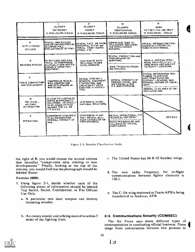
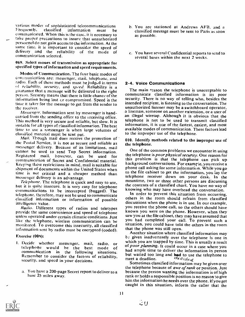
Figure 2-1 is a sample of a classification guide. Touse the guide, follow these three steps:
a. Upon learning the new information, group itunder a general type of information (A, B, C, D, E).
b. Look to the right to find the square that containsthe specific information you are classifying.
c. Determine the protection required for theinformation.
Let us see how these steps can be used. Suppose youhave to classify a photograph of a new aircraft cannonthat is a modification of an existing gun. Theimprovements cause the weapon to fire faster withmore accuracy. Applying the three steps, you wouldlook first to the general categories. A cannon would fitunder category B for weapon systems. Then looking to
r1CLASSIFYTOP SECRET
IF OISCLOSURE COULO:
IICLASSIFY
SECRET
IF DISCLOSURE COULD:
01
CL A.SS1 FY
CONFIDENTIALIF DISCLOSURE COMO:
IV
MARKFO" OFFIJAL USE ONLYIF OISCLOSURt: COULO:
..........
r A
INTFt LIGENCEEFFORTS
REVEAL OWN SUCCESSANO OR CAPABILITIES BYALLOWING FULLEVALUATION OF EF FORT.
REVEAL FACT WE KNOW:POTENTIAL EI:EMY IAA-TERIAL, TROO? OISPO-SITION, ETC.
CaMPROMISE SOME IN-TELLIGENCE AND COUN-TER INTELLIGENCI:REPORTS.
.........-..--
REVEAL INFORMATION FUR-NISHED BY FOREIGN tIA-TIONS IN CONFIDENCE.
sWEAPONS SYSTEMS
(1) DISCLOSE NUCLEARDATA, (2) COMPROMISERADICALLY NEW ANO EX-TREMELY IMPORTANTEQUIPMENT.
CDMPROMiSE DATARELATING TO NEWDE VE LOPMENTS.
REVEAL PROOUCTION ANDPROCUREMENT OFMUNITIONS.
SOME TECHNICALTRAIN-ING MANUALS.
REVEg..L CERTAIN TECH-NICAL DATA RELATINA.; 10ARMS WHIO1 ARE SUBJECTTO EXPZN: 1 LICENSING.
C
FORCE COMPOS)TIONAND OEPLOYMENT
COMPROMISE WORLD-WIOE COMPOSITIONAND DEPLOYMENT INWAR PLANS.
II
REVEAL STRENGIA.IDENTITY. EQUIPMENTC:NMPOSITION, ANDLOCATION CI- UNITSENGAGED IN HOSTILI-TIES.
REVEAL STRENGTH OFGROUND, NAVAL_, ANI)AIR FORCES N THEU.S. AND OVERSEM.
REVEAL INFORMATION PER-TAINING TO SPECIFICUNIT IDiNTIFICATION,CURRENT LOCATION, ANOGENERAL NATURE OF EQUIP-MENT.
ORDER:, 'CO AN AREA OF UN-DECLAREO WAR.
D
POLITICAL-MIL ITARY
INFORmATION
(1) LEAD TO A OEFINITEBREAK IN DIPLOMATICRELATIONS. (2) RESULTIN AN ARMED ATTACKAGAINST THE U.S. ORITS ALLIES.
JEOPAROIZE INTER-NATIONAL RELATIONS.
'....%...........,
-.%..........,
E
OPERATIONSI
li
COMPROMISE STRATEGICPLAN 00CUMENTINGOVERALL CONOUCT OFWAR.
COmpRomISE PLANSTHAT REVEAL WLI-TARY CAPABILITY ORPREPAREDNESS.
I
REVEAL OPERATIONAL, A s/ 11
NECHNICAL 00CTRIE/
RADIO FREQUENCIES ANOCALLSIGNS OF SPECIALSIGNIFICANCE.
231-513
I
Figure 2-1. Security Classification Guide.
the right of B, you would choose the second columnthat identifies "compromise data relating to newdevelopments." Finally, looking at the top of thecolumn, you would find that the photograph should belabeled Secret.
Exercise (008):
I. Using figure 2-1, decide whether each of thefollowing pieces of information should be labeledTop Secret, Secret, Confidential, or For OfficialUse Only.
a. A particular new laser weapon can destroyincoming missiles.
b. An enemy missile unit is being moved to within 5miles of the fighting front.
10
c. The United States has 60 B-52 bomber wings.
d. The new radio frequency for in-flightcommunication between fighter elements is126.1.
e. The C-5A wing stationed at Travis AFB is beingtransferred to Andrews AFB.
2-3. Communications Security (COMSEC)The Air Force uses many different types of
communication in conducting official business. Theserange from conversation between two persons to
Li
various modes of sophisticated telecommunicationsFrequently. classified information must becommunicated. When this is the case, it is necessary totake proper rrecautions to insure that unauthorizedpersonnel do not gain access to the information. At theName time, it is important to consider the speed ofdelivery and the reliability of the mode ofcommunication selected.
069. Select moues of transmission as appropriate forspecified types of information and speed requirements.
Modes of Communication. The four basic modes ofcommunication are: messenger, mail, telephone, andradio. Each of these methods must be jud&..d in termsor reliability, security, and speed. Reliability is aguarantee that a message will be delivered to the rightperson. Security means that there is little chance of theinformation being lost or compromised. Speed is thetime it takes for the message to get from the sender tothe receiver.
Af es.wnger. Information sent by messenger is hand-carried from the sending office to the leceiving office.This method is very secure and reliable, but slow. It issuitable for all types of elassified information. The besttime to use a messenger is when large volumes ofclassified material must be scnt out.
Mail. Though mail does receive the protection ofthe Postal Service, it is not as secure and reliable asmessenger delivery. Because of its limitations, mailcannot be used to send Top Secret information.Registered mail, however. can be used forcommunication of Secret and Confidential material.Keeping these restrictions in mind, mail is suitable forshipment of documents within the United States whentime is not critical and a cheaper method thanmessenger delivery is an advantage.
Telephorw. The telephone is quick and easy to use,but it is quite insecure. It is very easy for telephonecommunications to be intercepted (bugged). Thetelephone, therefore, may not be used to communicateclassified information or information of possibleintelligence value.
Radio. Different types of radios and teletypesprovide the same convenience and speed of telephoneunless operated under certain climatic conditions. Justlike the telephone, wireless communication can bemonitored. To overcome this insecurity, all classifiedinformation sent by radio must be encrypted (coded).Exercise (009):
I. Decide whether messenger, mail, radio, ortelephone would be the best mode ofcommunication in the following situations.Remember to consider the factors of reliability,security, and speed in your decisions.
a. You have a 200-page Secret report to deliver to abase 25 miles away.
I I
b. You are stationed at Andrews AFB, and aclassified message must be sent to Paris as soonas possible.
c. You have several Confidential reports to send toseveral bases within the next 2 weeks.
2-4. Voice CommunicationsThe main reason the telephone is unacceptable to
communicate classified information is its poorsecurity. There is no way of telling who, besides theintended recipient, is listening to the conversation. Theunauthorized listener may be a switchboard operator,a lineman, someone on another extension, or a user ofan illegal wiretap. Although it is obvious that thetelephone is not to be used to transmit classifiedinformation, it is one of the fastest, easiest, and mostavailable modes of communication. These factors leadto the improper use of the telephone.
010. Identify methods related to the improper use ofthe telephone.
One of the common problems we encounter in usingthe telephone is poor physical security. One reason forthis problem is that the telephone can pick up
ackground conversations. For examr le, you receive aphong call asking for some information. While you goto the file cabinet to get the information, you lay thetelephone receiver down on your desk. In themeantime, two or three other persons are discussingthe contents of a classified chart. You have no way ofknowing who may have overhead the conversation.
In order to prevent this situation from occurring,others in the room should refrain from classifieddiscussions when the phone is in use. In our example,you receive the phone call, so the others should haveknown you were on the phone. However, when theysaw you at the file cabinet, they may have assumed thatyou had completed your call. To prevent such asituation, you could have tolci the others in the roomthat the phone was still open.
Another situation where classified information maybs.; given inadvertently over the telephone is one inwhich you are trapped by time. This is usually a resultof poor planning. It could occur in a case where youhad ample time to deliver the information in personbut waited too long and had to use the telephone tomeet a deadline.
Sometimes classified information may be given overthe telephone because of awe of rank or position. Justbecause the person wanting the information is of highrank or holds a responsible position is no reason to givehim the information he needs over the phone. If you getcaught in this situation, inform the caller that the
information is classified or sensitive and that you willsee that it is delivered to him in the proper manner.
You may believe that you can cleverly disguiseclassified information when you use the telephone.What is wrong with this thinking? First, let us look atthe situation known as talk-around. This is a casewhere you try to get the information across bychanginz the words. For example, if you refer tc partsof a classified system as the thing in the lower right ofthe big black box under the rear seat, you haveattempted to talk around and disguise the information.However, any person who would go to the trouble ofmonitoring a telephone conversation would knowenough to determine what you actually meant.
Very closely related to talk-around is paraphrasing.The big difference is that talk-around Fives theimpression of double talk, while paraphrasing is usingdifferent words to say the same thing. For example, tosay that the repetition of the output waves occurs 1234million times a second means the same as the outputfrequency is 1234 MHz. Again, any spy could see rightthrough your disguise attempts.
Another faulty try is using incomplete or partialreferences. If you were talking about the NA/ ASQ-91Weapon Release Computer on the phone and referredto it as the 91, you would be using an incompletereference. Again, if you were discussing specificationsof the Nsytem, it would be ridiculous to assume that aneavesdropper would not know what system you weretalking about.
Some try to get around the problem by using a self-made reference system. This is an attempt to encodeyour own conversation by using your own code words.Such a system rarely works because few people areclever enough to refer to an item of informationwithout actually revealing names, subjects, etc., in theinformation.
Consider, too, that the discussion of unclassifiedinformation may cause problems. Gossip, chatter, andidle or unnecessary talk over the phone may give outmore information than you realize. For example, ifyou tell your buddy you can't go camping this weekendbecause you have a rush printing job may, whencoupled with other bits of information, indicate thedelivery of a new weapons system. Als, because you aretired, upset, or excited, you may let slip classifiedinformation of possible intelligence value. The mainidea, therefore, is to use the phone only for officialbusiness of unclassified information.
Exercises (010):
I. When classified information is overheard throughan unattended telephone transmitter, this is a resultof
2. If you give classified information over the phonebecause you are trapped for time, it is probably aresult of
3. If you give Colonel Jones c!assified informationover the phone, it is probably because of
4. List four methods used to disguise classifiedinformation over the phone.
12
2-5. Operations Security (OPSEC)The Air Force Operations Security (OPSEC)
Program, prescribed by AFR 55-30, OperationsSecurity, is an overall security program designed toenhance mission effectiveness. It is concerned with theinformation and activities that are sensitive becausethey give a hint to our enemy of our punch: they givethe enemy forewarning. OPSEC is intended to reducethe enemy's capability to collect useful intelligencedata about our operations and activities.
The first OPSEC program dealt with operations inSoutheast Asia. Its purpose was to prevent the enemyfrom gaining prior knowledge of our operations bytaking actions that ucnied him specific informationthat would decrease our effectiveness. Securityprocedures helped identify and eliminate those areas ofactivity patterns that showed the enemy something wasgoing to happen. The present OPSEC Program wasestablished in 1970. It was expanded to include allpersonnel and agencies connected with or having aknowledge of any operation, event, project, orprogram that required protection.011. State the purpose of OPSEC, list OPSECvulnerabilities, and indicate how OPSEC affects you.
Purpose. One of the basic principles of war is theelement of surprise. OPSEC is concerned with keepingtactical and strategic advantage on our side. We mustprotect knowledge of our plans, resources, andlimitations. Proper protection of classifiedinformation and material is part of it; so is protectionof what seems to be trivial or insignificant. In otherwor ds, we must protect what is sensitive. The purpose,then, of OPSEC is to prevent the disclosure ofinformation containing intelligence indicators that canbe used to degrade operational effectiveness.
Vulnerabilities. OPSEC weaknesses fall into threemajor areas: operations, procedures, andcommunications. To assist you in your daily activitieswe have included the following list of potentially weakareas.
2i
Operations.a. Sterotyped sequences of events.h. Coordination with other agencies that do not
have proper safeguards.c. Stereotyped flight patterns.J. Submission of unclassified reports at specific
times to specific units or levels of commands.Procedures.a. Public Information releases.h. Posting and / or transmission of operation orders,
flight plans, or air traffic control clearances, etc., inu nsecu re areas.
c. Posting duty rosters, transportation schedules, ordining hall schedules.
d. Distinctive emblems or paintings on vehicles,buildings, or aircraft.
e. Markings on supplies, which could show thelocation or starting date of an operation; that isnicknames, delivery deadlines, etc.
.1. Logistics buildup or positioning of supportmaterials and facilities.
g. Special briefings, meet:ngs, or religious services.h. Nicknames are a particular hazard since they flag
numerous actions associated with a particularoperation.
i. Exercising the plan or testing portions of a plan.C'ommunications.a. Plain language communications that are
associated with a planned operation and conductedduring the planning, preparatory, and executionphases.
h. Use of unchanging or infrequently changed callsigns or radio frequencies.
c. Stereotyped message characteristics (voice orteletype) which indicate particular types of militaryactivity.
d. Significant increase or decrease in message trafficvolume.
e. Activities of new communications facilities insupport of a planned operation.
OPSEC And You. As a photographer, you probablywill come in contact with more classified information
than the majority of the other career fields. You may becalled on to produce pictures of classified equipment,material, or even restricted areas. Some of your workwill involve duplicating classified slides or copy work.Since you know these things are classified, you won'tdiscuss them. But what about the unclassified butsensitive information you handle?
Suppose your lab is duplicating slides on junglesurvival. The contents of the slides may not beclassified but the fact that you are stationed in Alaskaadds significance to the information.
You may go into a restricted flightline area to takean unclassified picture of an award ceremony. Whileyou are there, you see packing crates addressed to"Operation Nighthawk." The fact that you saw them isnot classified. However, if you let it slip that youwonder where "Nighthawk" is, you may be passing onan intelligence indicator to a hostile agent.
Remember, as a photographer, you will see, hear,and document more sensitive information than mostother Air Force people. Don't try to impress peoplewith this knowledge. Keep it to yourself.
All forms of security contribute to one objective:M ission effectiveness. Information security,communications security, and operations security allenable us to keep an advantage over a possible enemyby denying him information about OUR activities andplans. If you keep all of this information in mind andremember the key points of security, you will neverbecome a security risk.Exercises (011):
I. State the purpose of today's OPSEC.
13
2. Why should you be particularly concerned withOPSEC?
3. What are the three major areas of OPSECweaknesses?
CHAPTER 3
Photographic Safety
ACCIDENTS DO NOT happen without cause.Accident records show that of all accidents, 88 percentare caused by unsafe acts of people, 10 percent byunsafe conditions that people allow to exist, and only 2percent by natural disasters. The identification,isolation, and control of these causes form thebackbone of accident prevention programs.
Certain phases of photographic work have apotential for producing accidents. Some of the work isperformed in total darkness or under extremely lowlevels of illumination. ',any photographic processesrequire the use of chemicals that, if used improperly,can cause serious injuries. However, if you are aware ofthe potential danger, and if you exercise the safetyprecautions covered in this text, the chances of yourbeing involved in an accident are extremely limited.
You should begin to develop good safety habits now.Accidents result in pain and suffering, needless wasteof manpower and materials, and could result in failureto carry out the assigned mission of the unit. For thisreason, safety is stressed throughout your training.Protect yourself from possible accidents by payingclose attention to the prescribed safety policies andprocedures. To do the job right, you must do it safely.
The following text information covering electrical,chemical, -.:ompressed gas, and mechanical safety ismeant to help you deal with some of the commonsafety problems you may encounter.
3-1. Electrical HazardsIn a still photographic facility, you are continuously
working with electrical equipment. Although adequatetraining in equipment operation and properinstruction in safety requirements can help to reduceaccidents caused by electricity, there is still thepossibility of human errorthat incalculable"something" that makes ground safety programsnecessary. Often, airmen are so thoroughly familiarwith their assigned tasks that they become negligentand the negligence results in preventable accidents.012. Specify the actions that should be taken to reduceelectrical hazards.
Many items of equipment used in a photographicfacility are electrically powered. To reduce thepossibility of electrical shock, burns, and equipmentdamage during use, special safety precautions should
be taken. For safe operation, you should check powercords for worn or frayed insulation, loose connections,and broken parts. You should regularly checkelectrical equipment to insure that it is properlygrounded. Be sure that all power cords have polarized,three-prong plugs attached. You can reduce thechances of being shocked by removing items ofjewelry,such as rings, watches, and bracelets, and make sureyour hands are dry before operating machines.
Overloading electrical circuits is extremelydangerous and is not permitted at any thne. All systemsinstalled in Air Force installations are equipped withfuses, circuit breakers, or other approved means toprevent accidental overloading. Use only fuses of theproper capacity. Never, under any circumstances, usetinfoil, solder, or other materials in place of a fuse.Never position items of electrical equipment, such astimers, where they can be accidentally knocked into adarkroom sink.Exercise (i12):
I . Which of the following actions are safe practices?
14
a.b.
C.
d.e.f.
Use polarized, three-prong plugs.Have personnel wear metal identificationbracelets at all times.Overload circuits.Use circuit-breakers.Perform regular inspections.Use solder as a temporary fuse.
3-2. Chemical SafetySome of the chemicals used in photography are only
skin irritants, but others can cause more seriousinjuries. All chemicals should be regarded as potentialpoisons and should be handled with caution. Acids andcaustic alkalies are dangerous and can cause severeburns if they come into contact with the skin. Somechemicals generate heat and may start fires when incontact with other materials. The following rules are toget you started thinking and practicing chemicalsafety.
013. Identify correct practices for working withphotographic chemicals.
Here are some of the precautions you should takewhen you handle or mix photographic chemicals:
a. Never smell a chemicai lirectly from the bottle.Instead, hold the bottle at a little distance from yournose and sniff its odor cautiously rather than inhalingdeeply.
h. Never taste a chemical.e. Handle all chemicals cautiously; some can
produce burns or skin irritations.d. When necessary, wear proper protective
equipment and clothing. When working with causticchemicals or acids, wear a rubber apron, rubber gloves,and goggles. If you are mixing powdered chemicals,use a respirator to prevent inhaling the dust.
e. When diluting strong acid with water, add theacid slowly to the water while stirring continuously;otherwise, the solution may boil violently and splatteron your face and hands, causing serious burns.Remember: ALWAYS ADD THE ACID.
.f. Be sure that the chemical mixing room is wellventilated. The fumes and dust from somephotographic chemicals will irritate your nose andeyes.
g. Store chemicals in airtight containers in a cool,dry place away from the sensitized materials. Chemicaldust, and vapors can damage paper and fiimemulsions. Be sure that chemical containers are labeledproperly.
h. If you spill caustic or toxic chemicals or acids onyourself or someone else, remove the soiled clothingand wash the affected area with a lot of water. Then getmedical help as soon as you can.
i. Nearly all of the chemicals you will come intocontact with in a photo lab are acid, alkali, orpetroleum base. DO NOT induce vomiting if you orsomeone else swallows photo chemistry; instead, getmedical help immediately. Tell the medical peopleexactly what was ingested.
j. If chemicals, either powder or liquid, get into youreyes, wash them immediately with lots of water.Exercise (013):
I. Read the following statements and check the onesthat describe safe practices when you are workingwith photo chemicals.
a. Wear a respirator when you mix powderedchemicals.
b. The best way to identify a chemical is to taste it.c. When you are mixing water and acid, always add
acid.d. Store chemicals in airtight containers.e. If photo chemicals are swallowed, induce
vomiting.f. If you get chemicals in your eyes, wash them with
lots of water.
3-3. Compressed GasesIn some still photographic facilities, compressed
gases, such as nitrogen or compressed air, are used
15
daily. Though not lethal in themselves, thesecompressed gases do pose a special type of safetyhazard.
014. Cite two potential safety hazards associated withthe use of compressed nitrogen gas.
The most frequently used form of compressed gas isnitrogen. Nitrogen is an odorless, colorless, tasteless,and chemically inert gas which is neither corrosive,explosive, nor flammable. Compressed nitrogen isused for gaseous-burst agitation. (Gaseous-burstagitation requires the release of a burst of nitrogen gasat controlled intervals through a series of tiny holeslocated in a distributor device placed at the bottom of aprocessing tank. When correctly monitored and firstreleased, the nitrogen burst imparts a sharpdisplacement pulse, much like a piston, to the entireprocessing solution. Then, .s the bubbles make theirway to the surface of the solution, a localized agitationactioin is provided around each bubble. By virtue oftheir great numbers and the random paths made to thesurface, the nitrogen bubbles provide effectiveagitation at the surfaces of film or paper suspended inthe solution.)
In some laboratories, cylinders of compressed air areused in equipment having air bearings, air squeegees,or pneumatic systems.
After what has just been said, you might wonderhow compressed gas could produce a situation thatcould be hazardous to you. Actually, it can bedangerous in two ways. First, since it is compressed,there is quite a large volume of gas present in thecontainer. If it is released in a confined area wherethere is a lack of adequate ventilation, nitrogen gascould easily asphyxiate you. Since nitrogen is odorless,colorless, and tasteless, it would be almost impossibleto identify the hazardous situation until it was too late.Good ventilation and careful inspection to insure thathoses and fittings are in good condition and properlyconnected will eliminate this potential hazard.
Secondly, because the gas is compressed, itscontainer is a source of danger. It must be handledcarefully to avoid being damaged. If the top is crackedor broken, the escaping gas would turn the cylinderinto a deadly projectile. Although accidents occurinfrequently, the possibility exists; so remember tohandle the gas cylinders with care. Secure all gascylinders to prevent them from being accidentallykn ,cked over. This is easily done by chaining them to awall.
Exercise (014):
1. From the following list, choose the two potentialsafety hazards associated with compressed nitrogengas.
a. The gas could cause asphyxiation.b. The cylinder could release lethal gas.c. The cylinder could become an unguided missile.d. The cylinder could burst into flames.
2
3-4. Connecting and Disconnecting Tanks ofCompressed Gas
At times, it may he necessary for you to disconnectan empty gas cylinder and connect a full cylinder tocomplete your mission. Therefore, you should knowthe proper procedures before trying to do this task. Thefollowing paragraphs are a summation of theprocedures described in Technical Order 42B5-1-2,Gas Cylinders (Storage Type), Use, Handling andMaintenance.
015. Indicate the prccedures used to connect tanks ofcompressed gas.
Connecting Tanks of Compressed Gas. The first stepin connecting a new gas cylinder is to crack or open thevalve slightly. This will blow any dust or debris out ofthe valve. After re-closing the valve, attach theregulator or union. You must insure that threads onthe regulator or union are the same as those on thecylinder valve. If the fittings are hard to turn, do notforce them. Check to be certain that the threads arecorrect and are not damaged. Threads must be of thesame type and have the same number of threads perinch to be engageable and to produce a satisfactoryseal. After attaching the regulator to the cylinder valve,check to see that the adjusting screw on the regulator isreleased before opening the cylinder valve. Whenthis is done, the lines can be connected to the regulator,
Disconnecting Tanks of Compressed Gas. Theprocedures for disconnecting tan'-s of compressed gasare basically the reverse of connecting the tanks.However, cracking the cylinder valve is not necessary.
Exercise (015):
I. List, in sequence, the steps in connecting acompressed gas cylidner.
3-5. Mechanical SafetyWith any type of equipment, there is always an
inherent safety problem. Trimmers have sharp edgesthat can cut; processing machines have gears that canpinch. The list of potential dangers is limitless.However, an alert individual, following the establishedsafety practices, can avoid becoming a victim of thesehazards. Remember, most safety rules are establishedas a result of someone's unfortunate experience. Don'tyou provide a reason for making a new rule.
016. Identify conditions, common to all machineoperations, that can lead to personal injury.
Plan Your Work. The more thoroughly you planyour work, the more likely you are to do it properlyand safely. When you perform a task without firstplanning for it, you usually do many unnecessaryoperations, make many mistakes, and use many unsafe
16
procedures. Since efficiency and safety are two of yourmost important considerations, it is essential that youplan your work thoroughly before you do it. Duringthis preoperational planning, you should organize alloperations necessary to complete the work properly,efficiently, and safely.
TIL: most important idea to bear in mind whenplanning a job is to check all pertinent safetyinstructions. These may concern such materials asprotective clothing, machine guards, or the type ofequipment you are using. Be sure to study safetyinstructions carefully, especially if you are doing a jobfor the first time. As you begin work each day, even oncomparatively simple tasks with which you arefamiliar, plan ahead to be sure all pertinent safetyprinciples are observed. If protective devices arerequired, have them available.
Just what does good discipline have to do with youand safety on the job? Perhaps we can best illustratethis by an example. Let's say that you are operating aprocessor. The local operating instructions tell younever to remove the side panels unless the machine isturned off. This is to prevent getting hands or looseclothing caught in moving gears. I. owever, you'vedone the job so many times that you know you canremove the cover without getting caught in the gears.So you ignore that caution and leave the machinerunning while removing the cover. Chances are youmay get by with it once or maybe several times.However, you are just possibly betting your arm thatyou can get by with breaking the law of good discipline.You know better, but since "old Sarge" isn't there toenforce the law, you think you can get away withshortening the procedure. You may cheat on safetysome of the time, but rarely all of the time, withoutgetting caught. Remember, once may be too often.
Stay Alert. Another basic principle of safety isalertness. Constant alertness is definitely a primerequisite in avoiding accidents. Fundamentally,alertness means paying attention, not just now andthen, but all of the time. Unless you pay close attentionto what you're doing at all times, you undoubtedly endup doing something wrong; again, you have a situationin which an accident may happen.
The enemies of alertness are external and internaldistractionsthings that occur outside of you andthings that occur inside of you, either mentally orphysically.
Perhaps, the most serious disturbances are thosethat you and your buddies create. It is inexcusable foryou or your buddy to do anything that could cause youor someone else to have an accident. This type ofexternal distraction usually takes the form ofhorseplay.
There are quite a few kinds of internal distractionsthat may destroy alertness. Whether they are mental orphysical, the number of possible internal distractions isjust too many to cover in detail. However, let us talkabout a couple of them so that we can see theimportance of keeping mentally and physically alertwhile on duty.
2 5
A mental distraction is perhaps most often caused bythinking about personal problems rather thanconcentrating on what you are doing. This violates theprinciple of alertness. The reason that mentaldistraction are especially hazardous is that it isimpossiblc for most people to pay attention to more thanone thing at a time. Unless you are a rare exception, youhad better forget about personal problems whileworking. If your personal problems are so great that theyinterfere with your work, let your supervisor know. Hemay be able to help you solve them. Don't let yourpersonal problems make you cause an accident thatdamages equipment or hurts somebody. This wouldcreate even bigger problems.
Another common mental distraction is daydreaming.This is particularly dangerous, since your mind canbecome completely absorbed in the pleasantness of adaydream, and your alertness is destroyed. There arevery few of us who haven't occasionally been caughtnapping by a sudden emergency that we otherwise wouldhave seen. Don't permit idle thoughts to de..royalertness. It can cause an accident.
17
The other kinds of internal distractions are physical.The most prevalent kinds are fatigue, severe pain, andillness. Most of us take care of severe pain and illness, orat least we should. The problem of fatigue cannotalways be eliminated. When you become fatigued, youshould recognize it and not let it go too far before youinform your supervisor.
ENereises (016):
From the following list, identify conditions,common to all machine operations, that might leadto personal injury.
a.b.
C.
d.e.f.
Organizing work operations.Planning a camping trip while operating apaper cutter.Keeping physically fit.Disregarding operating instructions.Poor work planning.Mental distractions.
7
CHAPTER 4
Photographic Laboratory Administration
IT IS NOTEWORTHY that in the Air Force, as youincrease your knowledge and improve your ability, youearn higher and higher rank; and with increased rank,you are given increased responsibility. With eachsubsequent step in grade, you can expect to assume somesupervisory responsibilities. As a laboratory manager.not only should you have a thorough technicalbackground, but you must also cope with an amazingamount of paperwork. Later, you will be running acomplex operation, and it takes a lot of forms, workorders, routing slips, data records, and control charts toinsure its effective and successful operation. In addition,there are regul- 'ins and operating instructions to coverjust about evet,,ning, and you must understand and usethem. All of this paperwork is the responsibility of thelaboratory manager.
Although right now you are taking directions ratherthan giving them, by learning a few of the problems ofadministration you will better understand what you arebeing asked to do. Specifically, in this chapter we coverwork requests and logs, files, publications, forms andreports, audiovisual records disposition, and copyrightand reproduction restrictions.
4-1. Work Requests and Logs
A photographic laboratory should be run like anyother business. Certain principles of good businessmanagement are applied to photo lab operations to insurean efficient operation. Each Air Force organization isgiven a specific operating budget within which they areexpected to operate. Also. the mission of theorganization and the workload involved determines thenumber of people assigned. The money expended toproduce photographic products and the manpowerrequired to produce them are expense factors that mustbe accounted for. Future budget and manpowerrequirements are mostly based upon what it cost the yearbefore to operate the photo lab.
017. State the importance of properly completing theAF Form 833 and state who fills in specified blocks onthe form.
Probably the most useful and important form used in aphotographic laboratory is AF Form 833, Request ForAudiovisual Services (fig. 4-1). When properlycompleted, the work request beccmes the source tor allpertinent information on a photographic assignment
8
including the cost of materials and the manpowerrequired to complete the assignment.
The work request is originated by the requester whocompletes blocks 5-15 on the front side of the form.Laboratory administrative personnel complete blocks16-21. Here, the information provided by the requesteris translated into specifics of the job to the done, and thetypes of finished products to be made. Photo labpersonnel completing blocks 16-21 must be veryknowledgeable in the scope of photo lab operations;including capabilities and work priorities.
The back of AF Form 833 (fig. 4-1A) provides spacesto record workload data and photo lab routing while thejob is in-house. This is probably where you will use theform. You may be the photographer or. perhaps, youwill process the film. Be sure that your figures areaccurate when you record the time you spent on the taskand the materials that you used. These figures from allwork requests are added up at the end of each month todetermine operating costs. When a work request iscompleted, your supervisor will check the quality of thefinished work.
.18
Exercises (017):
I. Why is it important to fill out the AF Form 833properly?
2. Blocks 8 and 9 of AF Form 833 are completed by
3. The quality control part of AF Form 833 isaccomplished by
018. State the purpose of a work request log and listthe data that it should contain.
An optional form used by most photo labs is a workrequest log. A work request log may be in the form of ahandwritten ledger or a locally produced form. Thepurpose of a work request log is to provide informationto administrative lab personnel on all work requestsreceived by the photo lab that are being worked on or
2 7
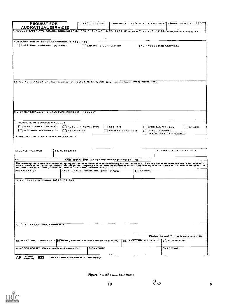
REQUEST FORAUDIOVISUAL SERVICES
I.DATE RECEIVED Z.ER+ORITY 1.DATE/TIME REQUIRED 4.WORK ORDER NUMBER
s REQuEsTER.s NAME, GRADE. ORGANIZATION AND PHONE NO. 8.CONTACT.IF OTHER THAN REOUES1ER (Narne.Grade 6 Phone No.)
7 DESCRIPTION OF SERVICES/PRODUCTS REQUIRED.i I STILL PHOTOGRAPHIC SUPPORT El GRAPHICS/COMPOSITION I AV PRODUCTION .'SERVICES
8 SPECIAL INSTRUCTIONS (i.. coordination required. loctron. dat, three. transportation erroilement. eir)
9.LIST MATERIALS/ORIGINALS FURNISHED WITH REOUEST
O. PURPOSE OF SERVICE /PRODUCTI- 1 EDUCA TION It TRAINING Ej PUBLIC INFORM^ TION (-- R&D T/E E.] MEDICAL /DENTAL CI OTHER1 3 INTERNAL INFORMATION 1::::1 RECRUITING ED COMBAT READINESS 1 IN TELLiGENCE /
IN VES TOGA TI ON /SECURI TYII SPECIFIC JUSTIFICATION (LAW APR 95-7)
'12.CLASSIFICATION 13. AUTHORITY 14. DOWNGRADING SCHEDULE
15. CERTIFICATION (ro be completed by certifying official)ry in conducting official buInmss. The request represents the minimum irpndi-
r a feta. official etternent or willfully making a false tatement is punishable under theTuh.e. m0714:4:I 7:1: tqed ni et a yunot I a etc! b.rc .rstrts Int :3. e(rs li:n
Uniform Code of Military Jutic or Title 189U.S. Code, Sctlen 1001 .)ORGANIZATION NAME. GRADE, PHONE NO. (Prffit or type) SIGNATURE
....--1.--16 Au CENTER INTERNAL INSTRUCTIONS
17. OUA...ITY CONTROL COMMENTS
Quality Control Review 6 Acceptance. !Iv
le DATETTIME COMPLETED lg. NAME. GRADE (Pereon notified for pick up) 20.DATE7TIME NOTIFIED I. NOTIFIED BY
<2 ACCEPTED BY (Name. Grade and Phone No) SIGNATURE DATE/TIME
AF ""'" 833PUG GO PRevloull EDITION %WILL MIR USED
Figure 4-1 . AF Form 833 (front).
19 2 9
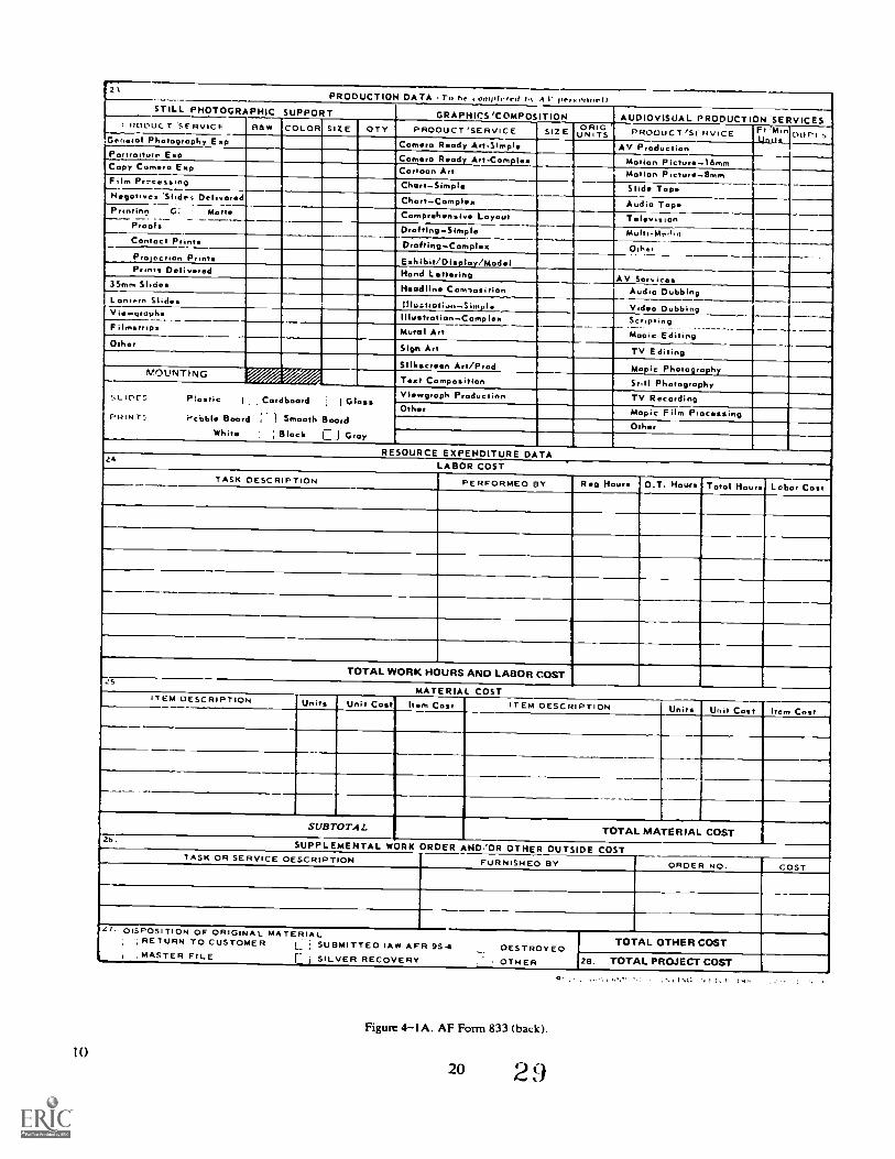
10
21PRODUCTION DATA . ro S. i unfiltered bv A I personnel/
STILL PHOTOGRAPHIC SUPPORTGRAPHICS/COMPOSITION AUDIOVISUAL PRODUCTION 'SERVICES1 RODULT 'SERVICE tria* COLOR SIZE OTT PRODUCT 'SERVICE SIZ ORIG'
Ni TS PRODUCT 'SERVICE Ft'fitiUnit: """General Photography Esti Comra Ready Art-Simpl AV Production
Portraiture Etta Comro Ready Art-ComplexCorroon Are
Motion Picturl6mmMotion Picturflmen
Copy Camera Emig
Film Pr.:cussing ChartSimple Slide Tope...Negatives 'Slides Delivered ChortComples Audio TopePrinting G: Matte Comprhnsiv Layout Telvivon
Proofs DraftingSimple Multi-MeritnConroe! Prinrs DroftIng-.Complez OtherProjection Pront Exhibit/Display/ModelPrints Delivered Hand Lttring AV Service.3Snin Slides HadlIn Com,osirion Audio Dubbing
L ontern Slides InuoiioGoreSimpiInutrotionCompIse
Vidleo DubbingScripting
V iewpropees
Filmstrips Mural Art Mopic EditingOther Sign Art TV Editing
SIII.scren Art/Prod biopic PhotographyMOUNTING ..1. .4" Trost Composition Still PhotographySL1C,FS Plastic I 1 Cordboard i., I GlossPRINT', PcOble Board :* 1 Smooth Board
Whirr. ; Block Ej Gray
VItegroph Production TV RecordingOthr Magic Film Processing
Orhr
RESOURCE EXPENDITURE DATA26LABOR COST
TASK DESCRIPTION PERFORMED BY Rg Hour O.T. Hours Tool Hours Labor Cot
TOTAL WORK HOURS AND LABOR COSTs
MATERIAL COSTITEM DESCRIPTION Units Unit Cost) Item Cosr ITEM DESCRIPTION Units Unit Cost Item Cost
SUBTOTAL TOTAL MATERIAL COST26
SUPPLEMENTAL WORK ORDER AND/OR OTHER OUTSIDE COSTTASK OR SERVICE DESCRIPTION FURNISHED BY ORDER NO. COST
DISPOSITION OF ORIGINAL MATERIAL; RETURN TO CUSTOMER L SUBMITTED lAW AFR 95.4
, DESTROYEDMASTER FILE r ; SILVER RECOVERY OTHER
TOTAL OTHER COST
26. TOTAL PROJECT COST
Figure 4IA. AF Form 833 (back).
20 2 9(
l 1 ..4 I
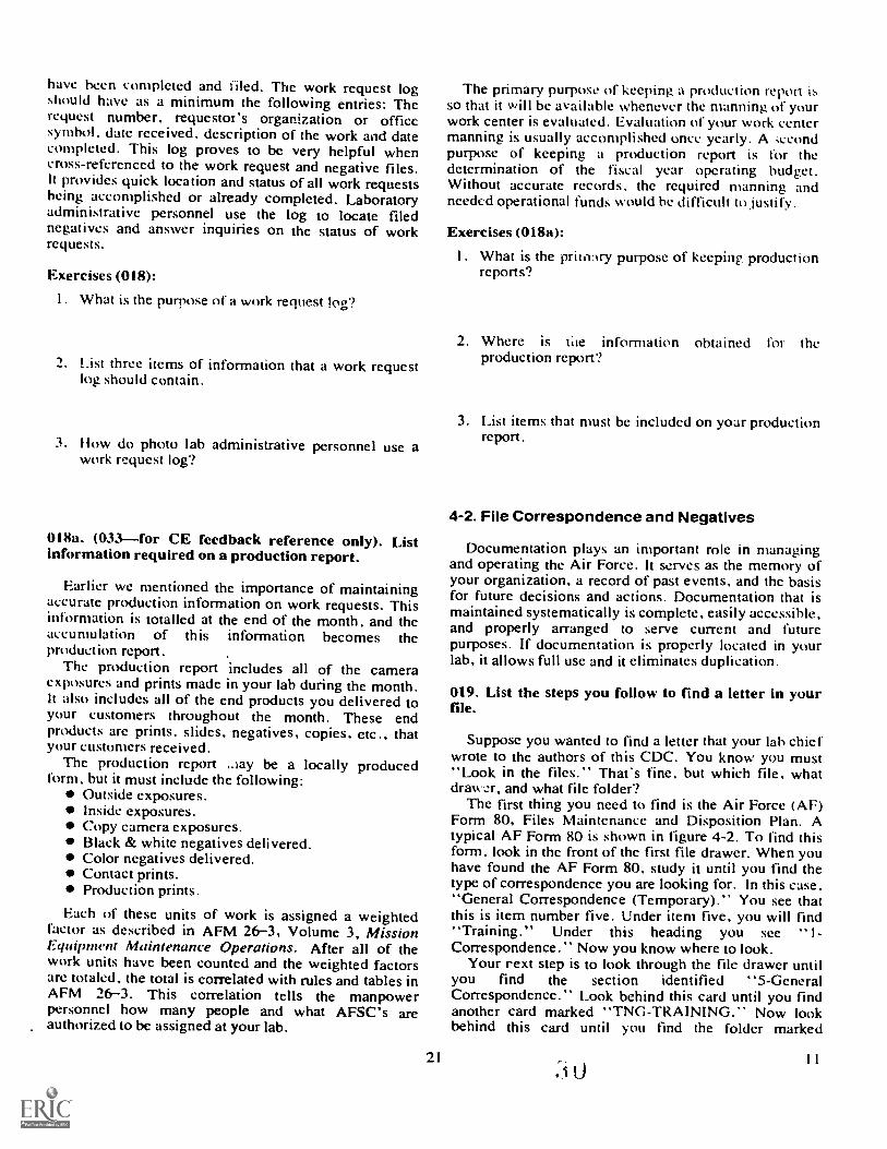
have been completed and filed. The work request logshould have as a minimum the following entries: Therequest number, requestor's organization or officesymbol, date received, description of the work and datecompleted. This log proves to be very helpful whencross-refcrenced to the work request and negative files.It provides quick location and status of all work requestsbeing accomplished or already completed. Laboratoryadministrative personnel use the log to locate filednegatives and answer inquiries on the status of workrequests.
Exercises (018):
I. What is the purpose of a work request log?
2. List three items of information that a work requestlog should contain.
3. How do photo lab administrative personnel use awork request log?
018a. (033for CE feedback reference only). Listinformation required on a production report.
Earlier we mentioned the importance of maintainingaccurate production information on work requests. Thisinformation is totalled at the end of the month, and theaccumulation of th is information becomes theproduction report.
The production report includes all of the cameraexposures and prints made in your lab during the month.It also includes all of the end products you delivered toyour customers throughout the month. These endproducts are prints, slides, negatives, copies, etc., thatyour customers received.
The production report ,tay be a locally producedform, but it must include the following:
Outside exposures.Inside exposures.Copy camera exposures.Black & white negatives delivered.Color negatives delivered.Contact prints.Production prints.
Each of these units of work is assigned a weightedfactor as described in AFM 26-3, Volume 3, MissionEquipment Maintenance Operations. After all of thework units have been counted and the weighted factorsare totaled. the total is correlated with rules and tables inAFM 26-3. This correlation tells the manpowerpersonnel how many people and what AFSC's areauthorized to be assigned at your lab.
The primary purpose of keeping a production report isso that it will be available whenever the manning of yourwork center is evaluated. Evaluation of your work centermanning is usually accomplished once yearly. A 'iecondpurpose of keeping a production report is for thedetermination of the fiscal year operating budget.Without accurate records, the required manning andneeded operational funds would be difficult to justify.
Exercises (018a):
I . What is the primnry purpose of keeping productionreports?
2. Where is tile information obtained for theproduction report?
3. List items that must be included on your productionreport .
4-2. File Correspondence and Negatives
Documentation plays an important role in managingand operating the Air Force. It serves as the memory ofyour organization, a record of past events, and the basisfor future decisions and actions. Documentation that ismaintained systematically is complete, easily accessible,and properly arranged to serve current and futurepurposes. If documentation is properly located in yourlab, it allows full use and it eliminates duplication.
019. List the steps you follow to find a letter in yourfile.
Suppose you wanted to find a letter that your lab chiefwrote to the authors of this CDC. You know you must"Look in the files." That's fine, but which file, whatdrawer, and what file folder?
The first thing you need to find is the Air Force (AF)Form 80, Files Maintenance and Disposition Plan. Atypical AF Form 80 is shown in figure 4-2. To find thisform, look in the front of the first file drawer. When youhave found the AF Form 80, study it until you find thetype of correspondence you are looking for. In this case,"General Correspondence (Temporary)." You see thatthis is item number five. Under item five, you will find"Training." Under this heading you see !-Correspondence." Now you know where to look.
Your rext step is to look through the file drawer untilyou find the section identified "5-GeneralCorrespondence." Look behind this card until you findanother card marked "TNG-TRAINING." Now lookbehind this card until you find the folder marked
"TNG-Correspondence." The last step is to lookthrough the folder until you find the letter you need. Thisis made a bit simpler if you know about when the letteryou need was written. The letters and documents in thefolder are filed by date, the most recent in the front.
Quite simple isn't it? If you have trouble the first timeyou try, remember that the first time you try almostanything, you will have a little trouble.
Exercises (019):
1. List the steps you must follow in order to find aletter in your file .
020. State how files of negatives are kept.
All photographic laboratories are required to maintaina file of the negatives that they produce. Since thedestruction or disposition of negatives and prints is notimmediate in all cases, it is necessary to file certainnegatives and prints in your laboratory. It may, at times,be necessary to reprint negatives. With an effectivefiling and indexing system, negatives can be located andreprinted as required. The file of negatives contains stillor ground photography negatives. Filed negatives shouldnot have a security classification higher than
confidential. Both ground and individual aerial (exceptaerial reconnaissance and mapping) still negatives maybe placed in this file.
Some of the negatives and photographs your labproduces are not considered to be file material. Except inunusual circumstances, the following examples shouldnot be filed:
a. Photographs of no value for retention; i.e., copynegatives that satisfy the needs of one user, trainingassignments, and other photographs that satisfy a localone-time need such as recreation or nonhistorical events.
b. Photographs from which reproduction is notfeasible because of improper focus, faulty processing, orcolor photographs in which color rendition is extremelypoor.
There are no cut-and-dried rules for your negativefiles as there are for the correspondence files. However,AFM 12-50, Disposition of Air Force Documentation.does contain rules on what to file and how long to keepit.
For example, according to Table 95-1 in AFM 12-50,original negatives of purely local interest can bedestroyed when their purpose has been served. You mustfile them until you destroy them.
Any negatives you produce for training or practicethat are of subjects not desired for record are destroyedwhen their purpose has been served. If you shoot somepictures of the front doorknob just to practice, you
2Ia13
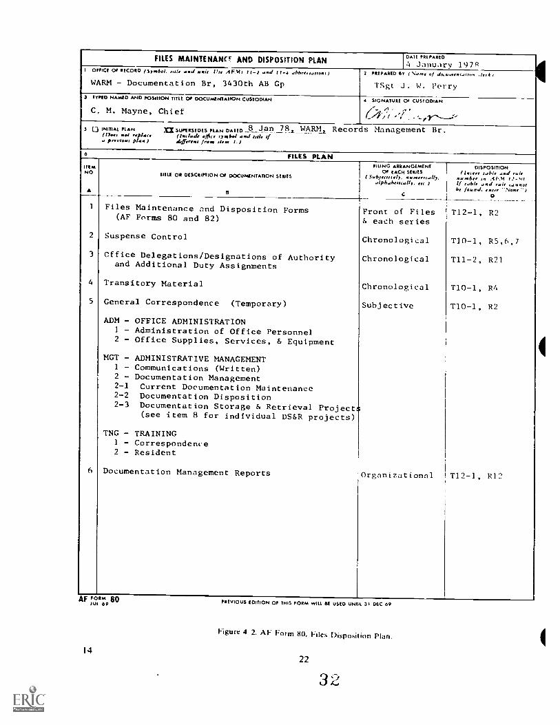
FILES MAINTENANC AND DISPOSITION PLAN DAIL PREPARED
4 January 19781 OFFICE Of RECORD (Symbol. tale aird row Vie 'IFNI I II and I V-4 abbreitattons)
WARM - Documentation Br, 3430th AB Gp2 PREPARED ET ( Ni.lIne Of do.u.nentatton .1,4 I
TSgt J. W. Perry3 TYPED NAMED ANO POSITION TITLE Of 00CUMENTATION CUSTOOLAN
C. M. Mayne, Chief
4 SIGNATURE 01 CUSIODIAN
f.././ / `; ..-,,,y,---J-
3 ij INITIAL PLAN =SUPERSEDES PLAN DATED 8 J an WARM Records Management Br.(00f, mei replace (berinelt office Iroaal and tale ifa pre i row plaw ) defferew: [rem glens 1.1
10 FILES PLANHEMNO
TITLE OR DESCRIPTION Of DOCUMENTATION SERIES
5
FILING ARRANGEMENTOf EACH SERIES
(SubJeciNely. femme...ally.alpbahetttallo. etc I
C
DISPOSITIONHANN :able and 14 if
numbe In .11..SI 11.-,0If sable and trate ...tnnotbe found. enter None I
D
Files Maintenance and Disposition Forms(AF Forms 80 and 82)
Suspense Control
Office Delegations/Designations of Authorityand Additional Duty Assignments
Transitory Material
General Correspondence (Temporary)
ADM - OFFICE ADMINISTRATION1 - Administration of Office Personnel2 - Office Supplies, Services, & Equipment
MGT - ADMINISTRATIVE MANAGEMENT1 - Communications (Written)2 - Documentation Management2-1 Current Documentation Maintenance2-2 Documentation Disposition2-3 Documentation Storage & Retrieval Project
(see item 8 for individual DS&R projects)
TNG - TRAINING1 - Correspondence2 - Resident
Documentation Management Reports
Front of Files& each series
Chronological
Chronological
Chronological
Subjective
Organizational
T12-1, R2
T10-1, R5,6,7
T11-2, R21
T10-1, R4
T10-1, R2
T12-1, R12
AF FOR" 80till 09
14
PREVIOUS EDITION OF THIS FORM WILL BE USED UNTIL 31 DEC 09
Figure 4 2. AF Form 80. Files Disposition Plan.
22
would not keep them in the negative file. However, ifthe doorknob had been broken and your pictures wereused for a damage report, you must keep the negativesin your files for 90 days. You should read AFM 12-50,Table 95 1, to find out which negatives to file and howlong to keep them.
The following information is not to be taken as a rulebut is included as a suggestion for a negative filingsystem. A negative file ledger, sometimes referred to asa negative log, is a numerical record of each negativethat is filed. When the number of a specific negative isknown, referring to this device provides pertinentinformation concerning the negative. Anothervaluable indexing device is the card index file. The titleof each negative is recorded on a card which is part ofan alphabetical file. The card file should be cross-indexed so that the information appears under severalletters of the alphabet. For example, in the first entry inthe negative file ledger, the letters P-S are shown in thecross-index column. In this case, the P stands forpa,;sport and the S stands for the first letter of the lastname of the subject.Exercises (020):
I. Complete the following statements regarding thefiling of negatives.
a. The negative file contains still or groundphotography negatives classifiedor lower.
b. A FM contains rules on whichnegatives to file and how long to keep them.
c. If you produce pictures for practice, youhave to file them.
4-3. Publications
The Technical Order (TO) System. The technicalorder system is the official means used to distributemilitay orders of a technical nature to all personnel.These publications, called technical orders (T0s),contain information, instructions, and safetyprocedures that deal with the inspection, operation,maintenance, and modification of Air Forceequipment and material. Some TOs have instructionsor information on subjects of a general nature such aspreparation of forms, policies pertaining to the TOsystem, and how to handle Air Force material. Inaddition to TOs, you must be concerned withregulations, operating instructions (Ols), andcommercial publications.021. From a list of statements regarding the types oftechnical orders, select those that are true.
23
The technical order system was developed so thatinformation will be available where and when it isneeded and in the most economical and efficientmanner possible. The groups of publications producedare described in the following paragraphs.
Technical Manual (TM). A TM containsinstructions designed to meet the needs of personnelengaged or being trained to operate, service, maintain,overhaul, install, and inspect items of equipment andmaterial.
Methods and Procedures Technical Order (MPTO).An M PTO establishes policy and providesinformation and instructions on safe methods andprocedures that relate to preventive maintenance,periodic inspection, Air Force product improvement,etc.
Time Compliance Technical Order (TCTO). TOsthat contain instructions for a modification or a one-tin-te inspection of Air Force equipment are called timecompliance technical orders.
Index Technical Orders. This kind of TO shows thestatus of all TOs, provides you with a way of selectingneeded publications, and groups publications thatpertain to specific items of equipment.
Abbreviated TO. This is primarily a work-simplification device, such as a checklist, inspectionworkcard, lubrication chart, or sequence chart.Exercise (021):
I. Read the following statements regarding types oftechnical orders and select the ones that are true.a. If you need to overhaul a camera, you should
read the technical manual.b. An MPTO must be complied with in less than 30
days.c. TCTOs describe one-time modification
procedures.d An abbreviated TO lists all of the official Air
Force abbreviations.
022. Find the technical order containing operatingprocedures for specific photographic equipment byreferring to reproductions of selected pages from a TOindex.
In your work you are concerned, to a large degree,with the technical manuals, since these publicationscontain detailed instructions and information requiredfor the operation, maintenance, inspection,installation, overhaul, and identification ofparts/components for the various types ofphotographic equipment. To use these manualsefficiently, you must know the indexing system.
Index-Type Technical Orders. This group oftechnical order publications (indexes) is an importantitem in your work. The problem of finding thetechnical manual you want can be solved by consultingthe proper index. There are a number of indexes, butthe one that you are most concerned with is theNumerical Index and Requirement Table (fig. 4-3) that
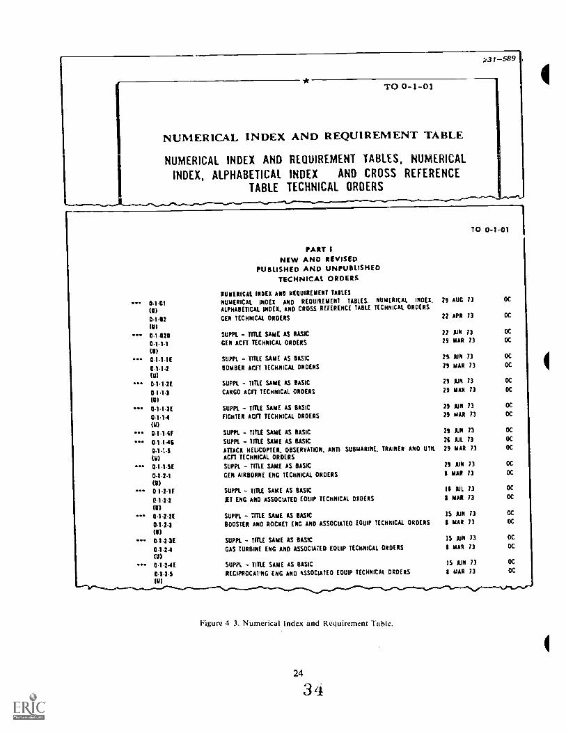
FINDEUMERICAL INDEX AND REQUIREMENT TABLE
NUMERICAL INDEX AND REQUIREMENT TABLES, NUMERICAL
X, ALPHABETICAL INDEX AND CROSS REFERENCE
TABLE TECHNICAL ORDERSTO
0-1-01
PARTNEW AND REVISED
PUBLISHED AND UNPUBLISHEDTECHNICAL ORDERS
i31-569
TO 0-1-01
0.1-01(U)
0-1-12
0-1-0200.1-1.1(11)
0.1-1.1E
.1.1-2(11)
0-1.1 2E
0-1-1.3
0.1-13E
0.1.1-IF
0.1.1-4112.14-5(U)
0-1-1-5E
0-1-2-1(V)0 1-2-1F
01-21fin0-1-2-2E
0-11-2-3
(11)
0.1-1
0.1.24fin0-1.24E0-1-2 5(U)
NUMERICAL INDEX A110 REQUIREMENT MILES
NUMERICAL tft0EX AND REQUIREMENT TABLES. NUMERICAL MEX.ALPHABETICAL INDEX. AND CROSS REFERENCE TABLE TECHNICAL ORDERS
GEN TECHNICAL ORDERS
SUPPt. - TIM SAME AS BASICGEN ACIT TECHNICAL ORDERS
SUPPL - TITLE SAME AS BASIC
BOMBER ACET TECHNICAL ORDERS
SUPPL - TITLE SAME AS BASIC
CARGO ACIT TECHNICAL ORDERS
SUPPL - TITLE SAME AS BASIC
FIGHTER ACF1 TECHNICAL ORDERS
SUPPE - TITLE SAME AS BASIC
SUPPL - TITLE SAME AS BASICATTACK HELICOPTER. OBSERVATION. ANTI- SUBMARINE. TRAINER ARO UMACFT TECHNICAL ORDERS
SUPPL - TITLE SAME AS BASIC
GEN AIRBORNE ENG TECHNICAL ORDERS
SUPPL - TITLE SAME AS BASIC
AT ENG AND ASSOCIATED EOUIP TECHNICAL ORDERS
SUPPL - TITLE SAME AS BASICBOOSTER AND ROCKET (NG AND ASSOCIATEO EQUIP TECHNICAL ORDERS
SUPPL - TITLE SAME AS BASIC
GAS TURBINE ENG AND ASSOCIATED EOUIP TECHNICAL ORDERS
SUPPL - TITLE SAME AS BASICRECIPROCAPNG ENG AND ASSOCIATE0 EOUIP TECHNICAL ORDERS
29 AUG 73
22 APR 73
22 lJN 7329 MAR 73
25 1JN 7329 MAR 73
29 AIN 7329 MAR 73
29 AIN 7329 MAR 73
79 AMI 7371 All 7329 mAR 73
79 AIN 73I MAR 73
II AK 73I MAR 73
15 AIN 73I mAR 73
15 AM 73mAR 73
)5 AIN 731 MAR 73
OC
OC
OC
OC
OC
OC
OC
DC
OC
OC
OC
OC
OC
OC
OC
OC
OC
OC
OC
OC
OC
OC
OC
Figure 4 3. Numerical Index and Requirement Table.
24
3 4
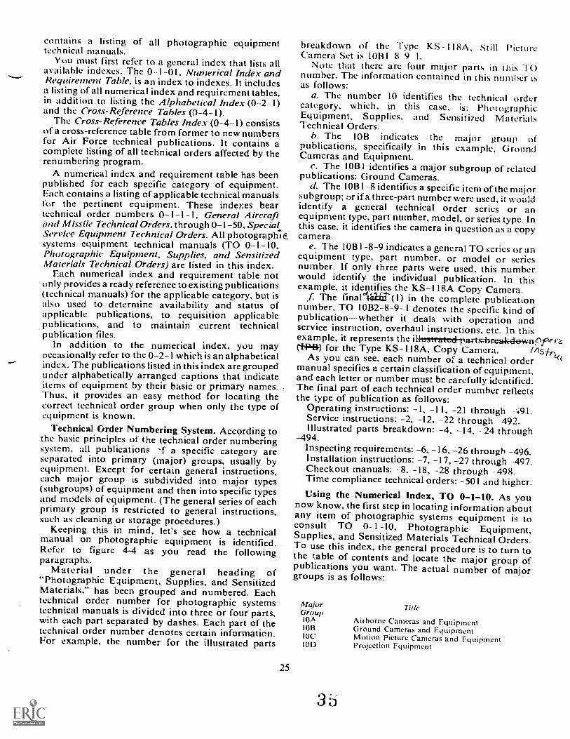
contains a listing of all photographic equipmenttechnical manuals.
You must first refer to a general index that lists allavailable indexes. The 0-1-01, Numerical Index andRequirement Table, is an index to indexes. It includesa listing of all numerical index and requirement tables,in addition to listing the Alphabetical Index (0-2-1)and the Cross-Reference Tables (0-4-1).
The Cross-Reference Tables Index (0-4-1) consistsof a cross-reference table from former to new numbersfor Air Force technical publications. It contains acomplete listing of all technical orders affected by therenumbering program.
A numerical index and requirement table has beenpublished for each specific category of equipment.Each contains a listing of applicable technical manualsfor the pertinent equipment. These indexes beartechnical order numbers 0-1-1-1, General Aircraftmid M issile Technical Orders, through 0-1 -50, Special.Service Equipment Technical Orders. All photographic.systems equipment technical manuals (TO 0-1-10,Photographic Equipment, Supplies, and SensitizedMaterials Technical Orders) are listed in this index.
Each numerical index and requirement table notonly provides a ready reference to existing publications(technical manuals) for the applicable category, but isalso used to determine availability and status ofapplicable publications, to requisition applicablepublications, and to maintain current technicalpublication files.
In addition to the numerical index, you mayoccasionally refer to the 0-2-1 which is an alphabeticalindex. The publications listed in this index are groupedunder alphabetically arranged captions that indicateitems of equipment by their basic or primary names.Thus. it provides an easy method for locating thecorrect technical order group when only the type ofequipment is known.
Technical Order Numbering System. According tothe basic principles of the technical order numberingsystem, all publications -f a specific category areseparated into primary (major) groups, usually byequipment. Except for certain general instructions,each major group is subdivided into major types(subgroups) of equipment and then into specific typesand models of equipment. (The general series of eachprimary group is restricted to general instructions,such as cleaning or storage procedures.)
Keeping this in mind, let's see how a technicalmanual on photographic equipment is identified.Refer to figure 4-4 as you read the followingparagraphs.
Material under the general heading of"Photographic Equipment, Supplies, and SensitizedMaterials," has been grouped and numbered. Eachtechnical order number for photographic systemstechnical manuals is divided into three or four parts,with each part separated by dashes. Each part of thetechnical order number denotes certain information.For example, the number for the illustrated parts
25
breakdown of the Type KS I I 8A, Still PictureCamera Set is 10B1 8 9 I.
Note that there are four major parts in this TOnumber. The information contained in this number isas follows:
a. The number 10 identifies the technical ordercategory, which, in this case, is: PhotographicEquipment, Supplies, and Sen5iti7ed MaterialsTechnical Orders.
b. The 10B indicates the major group ofpublications, specifically in this example, GroundCamcras and Equipment.
c. The 10B i identifies a major subgroup of relatedpublications: Ground Cameras.
d. The 10B1-8 identifies a specific item of the majorsubgroup; or if a three-part number were used, it wouldidentify a general technical order series or anequipment type, part number, model, or series type. Inthis case, it identifies the camera in question as a copycamera.
e. The 10BI-8-9 indicates a general TO series or anequipment type, part number, or model or seriesnumber. If only three parts were used, this numberwould identify the individual publication. In thisexample, it idestifies the KS-118A Copy Camera.
f The final 441..cit(1) in the complete publicationnumber. TO 10B2-8-9-1 denotes the specific kind ofpublication--whether it deals with operation andservice instruction, overhaul instructions, etc_ In thisexample, it represents the il-Ittstrerted-part-d-ewnefer(1-4443-) for the Type KS- I I8A, Copy Camera. /4,s
(4(As you can see, each number of a technical ordermanual specifies a certain classification of equipment,and each letter or number must be carefully identified.The final part of each technical order number reflectsthe type of publication as follows:
Operating instructions: -1, -II, -21 through 1.Service instructions: -2, -12, -22 through -492.Illustrated parts breakdown: -4, -14, 24 through
-494.Inspecting requirements: -6, -16, -26 through -496.Installation instructions: -7, -17, -27 through -497.Checkout manuals: -8, -18, -28 through -498.Time compliance technical orders: -501 and higher.Using the Numerical Index, TO 0-1-10. As you
now know, the first step in locating information aboutany item of photographic systems equipment is toconsult TO 0-1-10, Photographic Equipment,Supplies, and Sensitized Materials Technical Orders.To use this index, the general procedure is to turn tothe table of contents and locate the major group ofpublications you want. The actual number of majorgroups is as follows:
MajorGroup10AIORIOCIOD
35
Tide
Airborne Cameras and EquipmentGround Cameras and EquipmentMotion Picture Cameras and EquipmentProjection Equipment
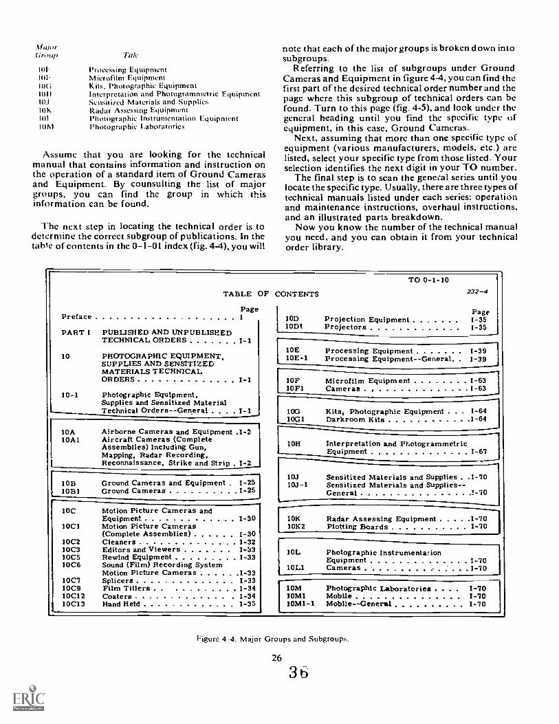
MahirGroup
101:1OF10G10II10.1
101S.
101
1OM
Title
Processing EquipmentMicrofilm EquipmentKits. Photographic EquipmentInterpretation and Photogrammetric EquipmentSensiti/ed Materials and SuppliesRadar Assessing EquipmentPhotographic Instrumentation EquipmentPhotographic I.aboratories
Assume that you are looking for the technicalmanual that contains information and instruction onthe operation of a standard item of Ground Camerasand Equipment. By counsulting the list of majorgroups, you can find the group in which thisinformation can be found.
The next step in locating the technical order is todetermine the correct subgroup of publications. In thetab'e of contents in the 0-1-01 index (fig. 4-4), you will
note that each of the major groups is broken down intosubgroups.
Referring to the list of subgroups under GroundCameras and Equipment in figure 4-4, you can find thefirst part of the desired technical order number and thepage where this subgroup of technical orders can befound. Turn to this page (fig. 4-5), and look under thegeneral heading until you find the specific type ofequipment, in this case, Ground Cameras.
Next, assuming that more than one specific type ofequipment (various manufacturers, models, etc.) arelisted, select your specific type from those listed. Yourselection identifies the next digit in your TO number.
The final step is to scan the genek-al series until youlocate the specific type. Usually, there are three types oftechnical manuals listed under each series: operationand maintenance instructions, overhaul instructions,and an illustrated parts breakdown.
Now you know the number of the technical manualyou need, and you can obtain it from your technicalorder library.
Preface
PART I
TABLE
Page
PUBLISHED AND UNPUBLISHEDTECHNICAL ORDERS I-1
OF CONTENTS
1 10DIODI
TO 0-1-10
Projection EquipmentProjectors
232-4
Page1-351-35
10E Processing Equipment 1-3910 PHOTOGRAPHIC EQUIPMENT,
SUPPLIES AND SENSITIZED10E-1 Processing Equipment--General. . 1-39
MATERIALS TECHNICALORDERS I-1 IOF Microfilm Equipm ent 1-63
10FI Cameras 1-6310-1 Photographic Equipment,
Supplies and Sensitized MaterialTechnical OrdersGeneral I-1 100 Kits, Photographic Equipment . . . 1-64
10GI Darkroom Kits 1-64
10A Airborne Cameras and Equipment .1-2I0A1 Aircraft Cameras (Complete
Assemblies) Including Gun,Mapping, Radar Recording,
10H Interpretation and PhotogrammetricEquipment 1-67
Reconnaissance, Strike and Strip . 1-2
10J Sensitized Materials and Supplies . .1-7010B Ground Cameras and Equipment . 1-25 10J-I Sensitized Materials and Supplies--10BI Ground Cameras 1-25 General *-70
IOC Motion Picture Cameras andEquipment I-30 10K Radar Assessing Equipment 1-70
IOCI Motion Picture Cameras 10K2 Plotting Boards 1-70(Complete Assemblies) 1-30
10C2 Cleaners 1-32IOL Photographic Instrumentwion10C3 Editors and Viewers
10051006
Rewind Equipment 1-33Sound (Film) Recording System 10L1
EquipmentCameras
1-701-70Motion Picture Cameras 1-33
1007 Splicers 1-3310C9 Film Titlers 1-34 10M Photographic Laboratories . . . . 1-7010C12 Coaters 1-34 10M1 Mobile 1-7010C13 Hand Held 1-35 10M1-1 Mobile--General 1-70
Figure 4 4. Major Groups and Subgroups.
26
3 6
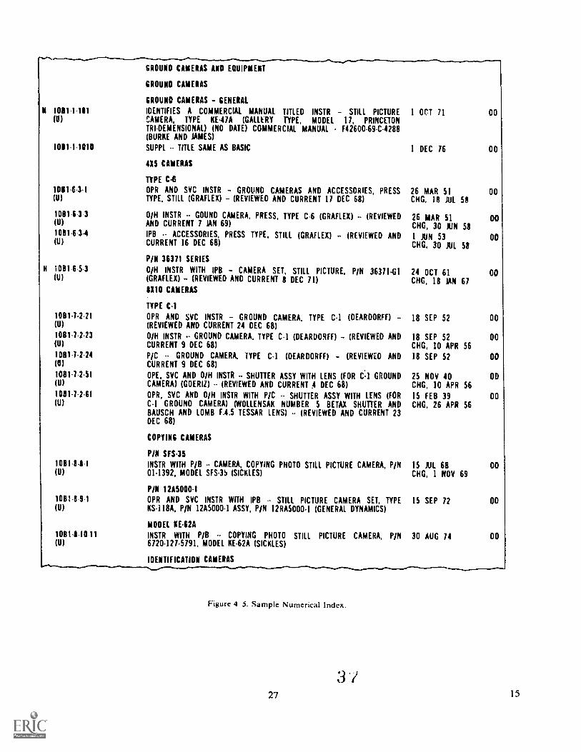
N 1081-1-111
GROUND CAMERAS AND EQUIPMENT
GROUND CAMERAS
GROUND CAMERAS - GENERAL
IDENTIFIES A COMMERCIAL MANUAL TITLED INSTR - STILL PICTURECAMERA, TYPE KE-47A (GALLLRY TYPE, MODEL 17, PRINCETON
I on 71 00
TRTDEMENSIONAL) (NO DATE) COMMERCIAL MANUAL - F42600-69-C-4288(BURKE AND JAMES)
1011-1-1010 SUPPL -- TITLE SAME AS BASIC 1 DEC 76 00
4X5 CAMERAS
TYPE C-6
1011.6.31 OPR AND SVC INSTR - GROUND CAMERAS AND ACCESSORIES, PRESS 26 MAR 51 00(11) TYPE, STILL (GRAFLEX) - (REVIEWED AND CURRENT 17 DEC 68) CHG, 18 JUL 58
108111 3 0/H INSTR GOURD CAMERA, PRESS, TYPE C-6 (GRAFLEX) (REVIEWED 26 MAR 51 00(U) AND CURRENT 7 JAN 69) CHG, 30 XIN 581081.6 3-4 IPB -- ACCESSORIES, PRESS TYPE, STILL (GRAFLEX) - (REVIEWED AND 1 JUN 53 00(U) CURRENT 16 DEC 68) CHG, 30 JUL 58
P/N 36371 SERIESH 1081151 0/H INSTR WITH IPB - CAMERA SET, STILL PICTURE, P/N 36371-G1 24 OCT 61 00
(U) (GRAFLEX) (REVIEWED AND CURRENT 8 DEC 71) CHG, 18 JAN 6781110 CAMERAS
TYPE C-I1081.7-211 OPR AND SVC INSTR - GROUND CAMERA, TYPE C-1 (DEARDORFF) - 18 SEP 52 00(U) (REVIEWED AND CURRENT 24 DEC 68)1081-7-213 0/H INSTR GROUND CAMERA, TYPE C-1 (DEARDORFF) - (REVIEWED AND 18 SEP 52 00(U) CURRENT 9 DEC 68) CHG, 10 APR 5610811-2-24 P/C -- GROUND CAMERA, TYPE C-1 (DEARDORFF) - (REVIEWED AND 18 SEP 52 00(U) CURRENT 9 DEC 68)1081-7151 OPE, SVC AND 0/H INSTR - SHUTTER ASSY WITH LENS (FOR C-1 GROUND 25 NOV 40 OD(U) CAMERA) (GOERIZ) -- (REVIEWED AND CURRENT A DEC 68) CHG, 10 APR 561081-7111 OPR, SVC AND 0/H INSTR WITH P/C SHUTTER ASSY WITH LENS (FOR 15 FEB 39 DO(U) C-1 GROUND CAMERA) (WOLLENSAK NUMBER 5 BETAX SHUTTER AND CHG, 26 APR 56
BAUSCH AND LOMB F.4.5 TESSAR LENS) -- (REVIEWED AND CURRENT 23DEC 68)
COPYING CAMERAS
P/N SFS-3510811-8-1 INSTR WITH P/B CAMERA, COPYING PHOTO STILL PICTURE CAMERA, P/N 15 JUL 68 00(U) 01-1392, MODEL SFS-3S (SICKLES) CHG, 1 NOV 69
Pill 12115000-11081.8 9 1 OPR AND SVC INSTR WITH IPB -- STILL PICTURE CAMERA SET, TYPE 15 SEP 72 OD(U) KS-118A, P/N 12A5000-1 ASSY, P/N 12RA5000-1 (GENERAL DYNAMICS)
MODEL KE-62A
1081-1 10 11 INSTR WITH P/B -- COPYING PHOTO STILL PICTURE CAMERA, PIN 30 AUG 74 DO(U) 6720-127-5791, MODEL KE-62A (SICKLES)
IDENTIFICATION CAMERAS
Figure 4 3. Sample Numerical Index.
:3 /27 1 5
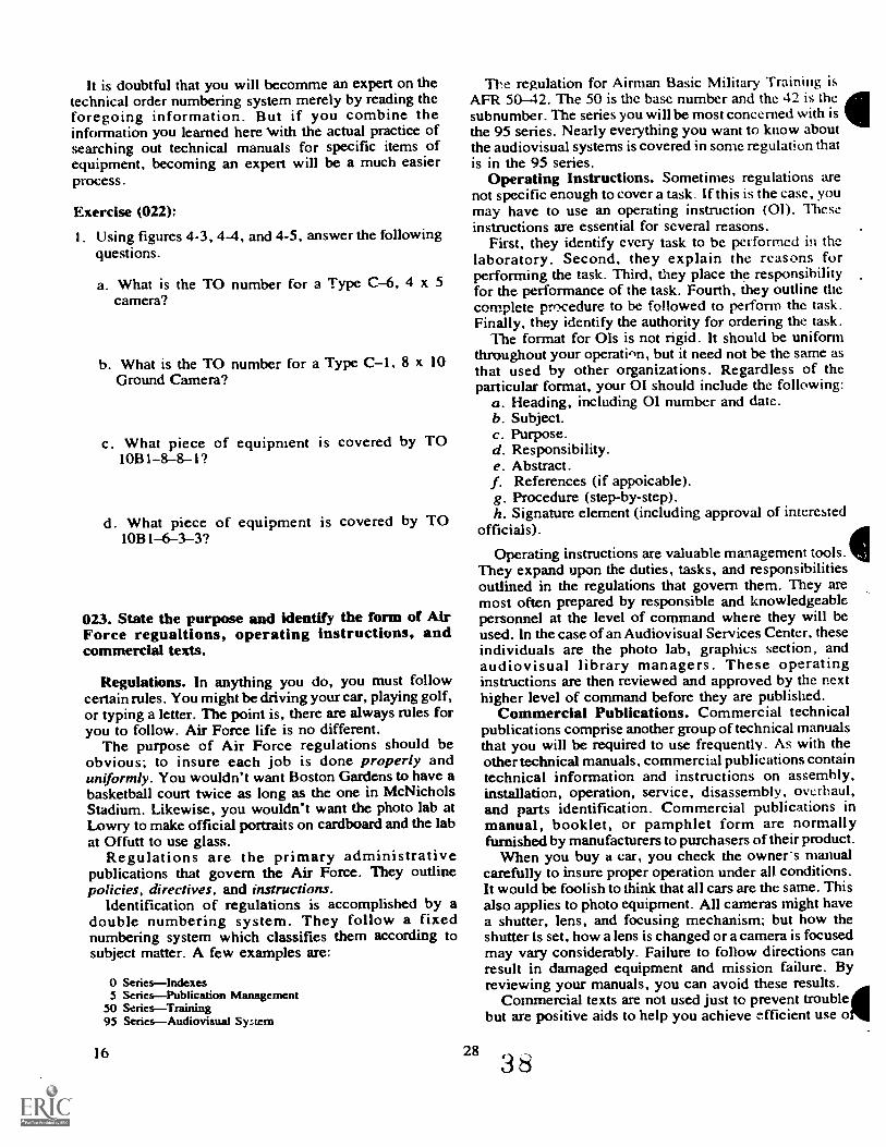
It is doubtful that you will becomme an expert on thetechnical order numbering system merely by reading theforegoing information. But if you combine theinformation you learned here 'with the actual practice ofsearching out technical manuals for specific items ofequipment, becoming an expert will be a much easierprocess.
Exerdse (022):1. Using figures 4-3, 4-4, and 4-5, answer the following
questions.
a. What is the TO number for a Type C-6, 4 x 5camera?
b. What is the TO number for a Type C-I, 8 x 10Ground Camera?
c. What piece of equipment is covered by TO10B1-8-8-1?
d. What piece of equipment is covered by TO1081-6-3-3?
023. State the purpose and identify the form of AirForce regualtions, operating instructions, andcommercial texts.
Regulations. In anything you do, you must followcertain rules. You might be driving your car, playing golf,or typing a letter. The point is, there are always rules foryou to follow. Air Force life is no different.
The purpose of Air Force regulations should beobvious; to insure each job is done properly anduniformly. You wouldn't want Boston Gardens to have abasketball court twice as long as the one in McNicholsStadium. Likewise, you wouldn't want the photo lab atLowry to make official portraits on cardboard and the labat Offutt to use glass.
Regulations are the primary administrativepublications that govern the Air Force. They outlinepolicies, directives, and instructions.
Identification of regulations is accomplished by adouble numbering system. They follow a fixednumbering system which classifies them according tosubject matter. A few examples are:
0 Serieslndexes5 SeriesPublication Management
50 SeriesTraining95 SeriesAudiovisual System
16
The regulation for Airman Basic Military Training isAFR 50-42. The 50 is the base number and thc 42 is thesubnumber. The series you will be most concerned with isthe 95 series. Nearly everything you want to know aboutthe audiovisual systems is covered in some regulation thatis in the 95 series.
Operating Instructions. Sometimes regulations arenot specific enough to cover a task. If this is thc case, youmay have to use an operating instruction (01). Theseinstructions are essential for several reasons.
First, they identify every task to be performed in thelaboratory. Second, they explain the reasons forperforming the task. Third, they place the responsibilityfor the performance of the task. Fourth, they outline thecomplete procedure to be followed to perform the task.Finally, they identify the authority for ordering the task.
The format for OIs is not rigid. It should be uniformthroughout your operation, but it need not be the same asthat used by other organizations. Regardless of theparticular format, your OI should include thc following:
a. Heading, including 01 number and datc.b. Subject.c. Purpose.d. Responsibility.e. Abstract.f. References (if appoicable).g. Procedure (step-by-step).h. Signature element (including approval of interested
officials).
Operating instructions are valuable management tools.They expand upon the duties, tasks, and responsibilitiesoutlined in the regulations that govern them. They aremost often prepared by responsible and knowledgeablepersonnel at the level of command where they will beused. In the case of an Audiovisual Services Ccnter, theseindividuals are the photo lab, graphics section, andaudiovisual library managers. These operatinginstructions are then reviewed and approved by the nexthigher level of command before they are published.
Commercial Publications. Commercial technicalpublications comprise another group of technical manualsthat you will be required to use frequently. As with theother technical manuals, commercial publications containtechnical information and instructions on assembly,installation, operation, service, disassembly, overhaul,and parts identification. Commercial publications inmanual, booklet, or pamphlet form are normallyfurnished by manufacturers to purchasers of their product.
When you buy a car, you check the owners manualcarefully to insure proper operation under all conditions.It would be foolish to think that all cars are the same. Thisalso applies to photo equipment. All cameras might havea shutter, lens, and focusing mechanism; but how theshutter is set, how a lens is changed or a camera is focusedmay vary considerably. Failure to follow directions canresult in damaged equipment and mission failure. Byreviewing your manuals, you can avoid these results.
Commercial texts are not used just to prevent troublebut are positive aids to help you achieve efficient use o
283 8

the gear. In fact, some manuals amount to a basic photocourse because the manufacturer wants the user to get themost from his product. You should take advantage of the
28 a
wealth of free information that is available. Moreover, allof the photo manufacturers have technical representativeswho may
17
he contacted for information on how to solve manyphoto problems.
Information is also available on expendable types ofsupplies. This information may not be in the form of atechnical manual. Instead, it may simply be a single-page bulletin. A photographer should constinuouslycheck such information to insure that he is takingadvantage of changes in film and chemistry. Forexample, most instruction sheets that come with a rollof film give helpful hints on exposure and processing toinsure top results. Such an information sheet bclongswith you and not in the wastebasket.Exercise (023):
I. Complete the following statements by filling in themissing term or phrase.
a. "The purpose of a regulation is to insure that eachjob is done and
b. Regulation.; outline policies, directives, and
c. The series of regulations that deal withaudiovisual systems is the series.
d. If the regulation is not specific enough, you mayneed to use a (an)
e. Ols identify every that is to beperformed in your lab.
f. Commercial publications are normallyfurnished by the
g. A commercial publication may be in the form ofa single-page
4-4. Audiovisual Records Disposition
Record photography is photography of significantmission and support activities of current or historicalvalue to the Air Force.
Of course, not all photography that you producequalifies as record photography. Many of your
assignments will be routine in nature passport andspecial assignment photographs, and transparenciesfor training and briefings are a few examples ofnon record photography. It is important that y ou beable to distinguish between record and nonrecordphotography.
024. From a list of photographic assignments, selectthose that should be considered record photography.
What distinguishes record photography fromnonrecord photography? The determination is oftensubjective. Generally speaking, any photography ofsignificant value should be retained. AER 95 3,Audiovisual Documentation Program, is the bestguide to use in making this determination. Thefollowing list of categories of assignments that areconsidered to be record photography is extracted fromAFR 95-3:
(I) Combat and combat support activities, test.(2) Air Forceevents of immediate news value, for
example, new aircraft or equipment, rescues, recordflights, major awards, and significant events.
(3) Events or actions of national or internationalnews interest in which the Air Force is taking part.
(4) Changes in mission or equipment, such as baseclosures, new aircraft or units assigned to a base, baseopenings or expansions.
(5) Operational exercises and special projects.(6) Research and development activities, for
example, first flights, roll-outs, missile launches,continuing development photography of newinventory material.
(7) Safety, such as aircraft accidents, accidentprevention programs.
(8) Counterinsurgency training and operation.(9) Community relations humanitarian and civil
actions, for example, flood relief, fire fighting,emergency blood donors, and aid to underpriviledgedchildren.
(10) Air Force personnel at work (all aspects), slichas flight-line crews, weather and radar men, training,medical, and religious activity.
(11) Special training activity, such as fire fighting,escape and evasion, paramedic, survival.
(12) Physical plant (once for record, then after anymajor changes, such as new construction).
(13) Physically handicapped persons working forthe US Air Force.
(14) Distinguished awards and decorations forpersonnel.
(15) Air Force Academy, flight training and officertraining activities.
(16) Unusual hobbies and duties of Air Forcepersonnel.
(17) Reserve, ANG, ROTC, and CAP significantactivities, such as search and rescue missions,humanitarian actions, disaster relief, etc.
(18) Athletic contests of more than local interest,such as interservice and intraservice tournaments end-of-season final games.
29
40
(19) Audiovisual material with unusual pictorialmerit, for example, photography of equipment,people. or activities taken with unusual lighting orfrom an unusual angle.
(20) Audiovisual coverage of Air Force aircraft,missiles, and other equipment, taken from all angles,both in the air and on the ground.
(21) Color transparencies of artists' concepts of newaircraft, weapon systems, etc.
Nonrecord photography is usually any photographythat does not fall within the above-mentionedcategories. Also, negatives and prints of the abovesubjects that are of inferior quality, repetitiousdocumentation nf the same subject, and extra copies ofphotographs already submitted to still depositories arenonrecord photography. Another example ofnonrecord photography is that of photographs used bythe base information office which are of purely localinterest. Still photography that has been selected forsubmission to USAF still depositories is recordphotography; any items not selected are nonrecordphotography.
Exercise (024):
I. From the following list of photographicassignments, select those that should be consideredrecord photography:
a. Photographs of a new radar system beinginstalled on the base.
b. Photoglaphs of a damaged supply shipment.c. Photographs of base firefighting personnel
assisting the local fire department in putting outa large fire in the community.
d. A passport photograph of an airman goingoverseas.
e. A visit to your base by the Secretary of the AirForce.
4-5. Lettering and Captioning of StillPhotography
All record materials produced by your laboratorymust be identified to insure proper coordination ofnegatives and prints covering a wide variety of subjectsthat are forwarded to USAF still depositories frominstallations all over the world. Without properidentification, materials forwarded would be uselessand, therefore, not acceptable as recordbhotography.
02.S. State how to letter negatives.
Once materials have been selected for forwarding toUSAF still depositories they must be lettere...1. AFR95 4. Audiovisual Records Disposition Program, isyour guideline for lettering and captioning stillphotography. Negatives must be lettered in the widestclear margin of exposed original materials. Letter withindelible ink on the acetate (base) side of the negative.Starting from the left, record the followinginformation: negative number, claendar year,
exposing unit, and security classification of thematerial. Never letter in an important part of anynegative. When there is not enough room on thenegative, attach a titling (acetate) strip to the negat ive..1-he negative number that you record is a locallyassigned number. These numbers are in sequencestarting with the number one on the first day of thecalendar year. Example:
umber Year UtUt Security
1 78 135G AliGp CONFIDEN.FIAl.
Negatives that arc part of a sequential roll arcidentified by adding an alpha suffix to the negativenumber; la, lb, etc.Exercise (025):
I. Complete the following statements.
a. The negative identification number isassigned.
b. Lettering is done on the side of thenegative.
c. When negatives from a sequential roll arelettered, an is added to the negativenumber.
d. Starting from the left, record this information:
andmaterial.
of the
026. From a list of statements regarding captioningand identifying prints, select those that are true.
Lettering th -! negatives is just the first step inidentifying record still photography. Captions for eachphotograph must be made and all prints released mustbe identified on the back of the print
Each negative of record photography must becaptioned. Captions are recorded on AF Form 397,Audiovisual Caption (fig. 4-6), for a series ofphotographs about the same subject or AF Form 398,Photographic Assignment Data, (fig. 4-7) (for anindividual negative). These are the only forms that canbe used to record captions. The AF Form 398 is veryuseful lbeca use it can be initiated to record assignmentdata before the assignment is photographed. To
30
41
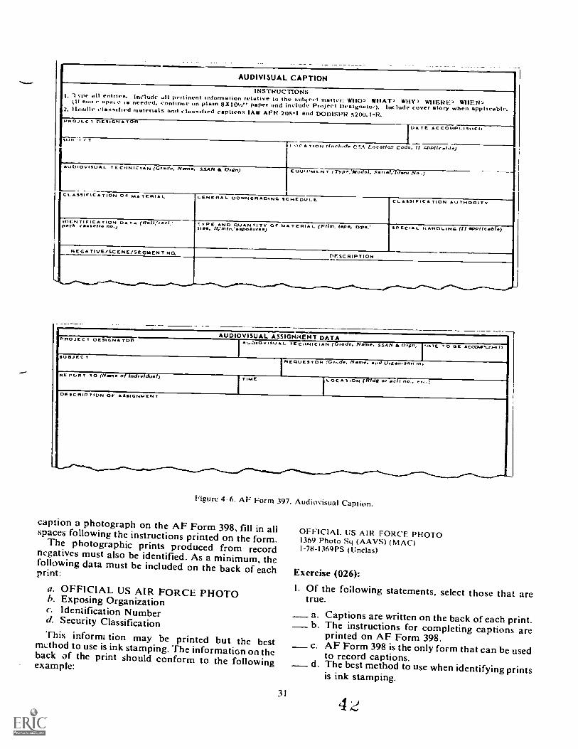
AUDIVISUAL CAPTION
INSTRUC11ONSI. Type all entries. Include all pertinent information relative to the subject matter: WHO? WHAT) WHY? WHERE? WHEN'?ill mot e apaTe is needed. continue on plain 8Xl0i/i'r paper and include Project Designotoc). Include cover story when applicable.2. liana le classified materials and claasified captions IAW AFR 20S-I and DODISPR 5200.1-R.ririo)Tc 1 DESIGNATOR
DA TE ACCOMPLISHED
5 I t' T
II HC A T ION (foe-holm CSA Location Coda, lf FPPIic.aht.)
IUDIOVISUAL TECHNICIAN (Grdo, Nome. SSAN Oran) EOUIPMENT (Type, Moe Ser . , 1 aot No.)
CL SSIFIC A TION OF MA TERI A l OENERA I_ DOWNGRADING SC HEDUL E CLASSIFICA FION AUTHORITY
IDENTIFIC A TION DAT e (ROSI,`reel:pack TYPE AND QUAN TI T. OF MA TERIA L (FRJ..1.P.. rsirri,'alaft. ffirnin,alsourdo SPECIAL DANDLING (71 oPPlIcble)
NEGATIVE/SCENE/SEGMENT NO.CIF.SCRIPTION
...._ ..-......._ _..... -......-...--_
....,..AUDIOVISUAL ASSIGN:4(NT DATAPROJE T DESIGNATOR
At_.DIOVISU AL TECHNICIAN (Grade. NOM.. SSAN Orgn,. ,ATE TO SE AC CGNFN-cA-41 :I
sUlfJEC TREOvEs TOR /Gr..de, Name, nd organlzer, ,n,
REPORT ro (Name of indleTdual) TIME LOC A T ION (Bldg Or cut no., er. )
DESC RIP TION OF ASSIGNMENT
A ...."....- ............._ -0..1 .......
Figure 4--6. AF Form 397. Audiovisual Caption.
caption a photograph on the AF Form 398, fill in allspaces following the instructions printed on the form.The photographic prints produced from recordnegatives must also be identified. As a minimum, thefollowing data must be included on the back of eachprint:
a. OFFICIAL US AIR FORCE PHOTOb. Exposing Organizationc. Identification Numberd. Security ClassificationThis inform tion may be printed but the bestmethod to use is ink stamping. The informatiGn on theback of the print should conform to the followingexample:
31
OFFICIAL US AIR FORCE PHOTO1369 Photo Sy (AAVS) (MAC)I-78-1369PS (Unclas)
Exercise (026):
I. Of the following statements, select those that aretrue.
a Captions are written on the back of each print.b The instructions for completing captions areprinted on AF Form 398.
c AF Form 398 is the only form that can be usedto record captions.d The best method to use when identifying prints
is ink stamping.

CAPTIONI nail of Ph010 2. 1.1,070 tpiNlilicAlION NO.
3. List complete name,, left to right. of principles.4. List what happened. what is important. Why is it
important.
S. Location of the event.O. Give complete project identification and explain
nicknames, if used.
A GPO 14110-1M-nle
PHOTOGRAPHIC ASSIGNMENT DATA
Calf PROJECT O.
1CCATION
RiOuESTOR i ORGANIZAIION
1
utopill TO PHONE O.
IWISDING OR AIRCRAFT
n1s,RIRTION oF ASSIGNMENT
PnoToGRAPHIR PHOTO CLASS
AF ""u 398 PREVIOUS EDIIION 15:AN et, OBSOLETE. g
Figure 4 7. Al Form 398, Photographic Assignment Data.
4-6. Disposition of Record PhotographyStill record photography is submitted to the USAF
Central Still Photographic Laboratory on a quarterly
basis. Submission date is the last working day of eachending quarter. When no record pohotoeraphy hasbeen accomplished by your lab during a quarter, then anegative report is required.
027. State how still record photography istransmitted.
Each separate submission must include three things:the original negative or negatives of the assignment,each properly lettered IAW AFR 95-4; captions ( Al'Form 397 or 398); and a high quality 4 - x 5-inch (10 x12 cm) print of each negative. If you are submittingnegatives that are larger than 4 x 5 inches, then youshould submit a contact (same size) print.
Each original negative is placed in a separateprotective envelope along with the caption. For a seriesof photographs of the same subject, captions areplaced on AF Form 397 to accompany the negatives.These are the basic procedures to use. For detailedinstructions and special instructions on submittingitems such as transparencies and 35mm negatives, referto AFR 95-4.
Exercises (027):
I. The three items that make up a package forsubmission to the USAF Central Still PhotographicDepository are and
32
2. A print should be submitted whennegatives are larger than 4 x 5 inches (10 x 12 cm).
4-7. Copyright and ReproductionThe laws protecting photographs are numerous and
involved. The most important regulations are thecopyright laws which are promulgated by the FederalGovernment. A basic understanding of the copyrightlaws that affect reproductionof photographs and othermaterials is important to every A i r Forcephotographer. Also, there are Federal and Air Forceret ulations which, in addition to the copyright laws,prt,hibit the reproduction of certain materials. Allpersonnel in a photographic laboratory must concernthemselves with the copyright laws and Air Forceregulations governing copyrights. To reproducecopyrighted material without specific written releasefrom the holder of the copyright is not permissible.
028. State whether, according to the copyright laws,certain subjects may be copied, and give other detailsof the copyright laws.
The most common areas in a photographiclaboratory concerned with copyright restrictions arethe administrative and reproduction sections. Your labwill receive numerous work requests to reproduce
4 3

photographs, publications, and artwork for operationaland training purposes. Occasionally, materials to bereproduced are copyrighted. Copyrighted materials areusually marked %. ith thc symbol and are accompaniedby the name of the company or person holding thecopyright. When you handle work requests forreproduction, it is your responsibility to check allmaterials to be reproduced to insure that none of themarc copyrighted.
Rights. A photographer has a property right to thephotographs in his possession. in addition, thephotographer may take steps to protect the artistic skilland mental effort that he applied to produce an originalphotographic idea. This additional protection, the onemost violated, is called a copyright.
Article I , Section 8, of the United States Constitutionempowers Congress to promote the progress of scienceand the useful arts, by securing for limited times toauthors and inventors the exclusive right to theirrespective writings and discoveries." (The term
writings has bcen construed to include photographs.)Under this Constitutional mandate, the Copyright Statutewas enacted. The Copyright Act specifically prohibitsthe use, without permission, of a person's mental labors.
A photographer's work can be protected by threeseparate copyright laws; i.e., common law copyright,statutory copyright, and international copyright law. Thecommon law (nonstatutory law) protects anyunpublished photograph. The photographer does nothave to file for this protection. The statutory copyrightpreserves the photographer's rights in pictures that hepublishes. The copyright must be obtained throughappropriate application with the Federal Governmentbecause States do not have the power to grant copyrightprotection. An international copyright that protects thephotographer's works when published in certain foreigncountries may be obtained.
The point to remember in regard to the publication ofphotographs is that the owner of the picture has certainpersonal rights which are specifically protected under thelaw. When you need to use another person'sphotographs, you musrget written permission to usethem. The owner of the photograph has the followingrights:
The right to forbid copying of the photograph.The right to sell the photograph outright.The right to sell particular use of the photograph.The right to forbid exhibition of the photograph.The right to sue in civil couns if any unauthorizeduse of the photograph is made.
In addition to facing a civil damage suit, a copyrightinfringer may also be criminally prosecuted, which maylead to imprisonment and paying of fines.
The thrust of the copyright laws is reaffirmed by AirForce regulations. The regulations clearly-state that noperson of the United States Air Force shall adopt or useor shall authorize the adoption or use for or on behalf ofthe Government or Air Force:
a. Any article, when it is known to hc propfietary(privately owned).
b. Any matter in which it is known, or there is reasonto believe, a copyright exists unless consent of the ownerhas been obtained or authorization has been given by theAir Force.
In addition to restrictions placed upon thereproduction of copyrighted material, the Federal andState Governments restrict the copying and reproductionof many other documents. Attachment 2 of AFR 6I ,Policies, Procedures and Standards Governing AirForce Printing, Duplicating, Copying and Microform.lists many of the items that you cannot reproduce orcopy. The following is an excerpt from the regulation:
33
Unlawful Reproduction
( I ) Reproduction of any of the following materials is unlawfulunless authorized under regulations pursuant to law or exceptedby paragraph (2) below:
a.
b.
C.
d.e.f.
g.
Adjusted compensation certificates for veterans of theWorld War.Automobile licenses, drivers' licenses, and auto: obiletitles in certain states.Certificates of citizenship or naturalization.Certification of war necessity.1mm i gratitm papers.Licenses issued to marine officers.Obligations of any foreign government. hank, orcorporation.
h. Obligations or securities of the United StatesGovernment. including: Bonds. Certificates ofIndebtedness: National Bank Currency: ('oupons.United States Notes: Treasury Notes: GoldCertificates: Silver Certificates; Fractional Notes.Certificates of Deposit: bins. cheeks, or drafts formoney. drawn by or upon authorized officers of theUnited States: Passports. Selective ServiceRegistration Certificates.
i. Official badges. identification cards, and other insigniaof the design prescribed by the head of any departmentor agency of the US Government.
(2) Exceptions: Printed illustrations of paper money. checks.bonds, and other obligations and securities of the United State%and foreign governments are permissible for numismatic (coincollecting), educational. historical. and newsworthy purposes.The illustrations must be in black and white and ritikA he of asize less than 3/41ths or more than I V; times the size uf thegenuine instrument. The illustrations must appear in articles.books, journals, newspapers. magazines, or alhunts. Noindividual facsimiles are permitted. Printed illustrations ofUnited States postage stamps are permissible for philatelic(stamp collecting), educational. historicaL and newsworthypurposes in articles. books, journals, newspapers. or albums.The illustrations will be in black and white and may be the exactsize of a genuine stamp. Colored illustrations are prohibited.United States revenue stamps may be illustrated under the sameconditions and for the same purposes as illustrations of UnitedStates postage stamps. Printed illustrations and photographs ofcoins of the United States and foreign countries are permissiblefor any purposes including advertising. Token, disks or devicesin the likeness or similitude as to the design. color, or theinspection thereon of the coins of the United States or of anyforeign country are prohibited.
Finally, the making of indecent" or obscene
19
photographs or the possession of them is a court-martialoffense as being scandalous conduct or conduct to theprejudice of good order and discipline. Thephotographing, copying, or reproduction of any suchmaterial is punishable by court-martial with penalties upto $5,(XX) or 5 years imprisonment, or both.
In your situation as an Airman working as aphotographer for the United States Air Force, what youphotograph on the job is not your property. This ruleapplies whether or not you use personal photographicequipment to cover official assignments. The followingparagraph extracted from AFR 95-1, USAF AudiovisualResources and Functions, outlines this policy:
All audiovisual materials produced or collected by Air Forcemembers or employees in the course of their official dutiesbecome the property of the Department of the Air Force.Personal use of such audiovisual material for sale or any otherreason not directly related to an official Air Force activity isprohibited without the specific written approval of an official soauthorired by law, regulation, orders, or other competentauthority
Air Force members or employees, by choice or agreement,occasionally use personally owned equipment or supplies in thecourse of their official duties. However, this policy on personaluse of audiovisual material applies regardless of whetherpersonally owned equipment and supplies or Governmentresources are used to obtain or reproduce the material.
Finally, if copyrighted material is to be reproduced, acopyright release must be obtained from the holder of thecopyright. It is the responsibility of the requester toobtain the copyright release. AFR 110-8, Inventions,Patents, Copyright, and Trademarks, outlines theprocedures to be followed in obtaining a copyrightrelease. The release must accompany the material to bereproduced and should be placed in laboratory files afterthe work has been accomplished.
Exercises (028):
I. Which of the following subjects can be legallycopied?
a. Immigration papers.h. United States Bonds.c. Passports.d Selective Service Registration Certificates.e. One dollar bill copies 150 percent in black and
white.1. Color picture of an 8¢ stamp.g. Black and white picture of a revenue stamp.h. Color photograph of a dime.i. Identification badge.j. Mexican dollar for numismatic purposes.
2. Complete the following statements regarding thecopyright laws.
a. The purpose of the copyright laws is to protectthe photographer's labors.
h. The copyright laws are controlled by theGovernment.
c. The copyright 1 Iws have been reaffirmed byAir Force
d. The common law protects anyphotograph.
e. As a copyright infringer, you may facedamages and
prosecution.
4-8. Equipment Responsibility
When you buy an article from a store, the moment thesales clerk completes the transaction, the store drops itsaccountability. The article then becomes your propertyand responsibility. You alone are accountable for it andyou can do with it whatever you please.
Similarly, whenever a supply person issues an AirForce item to you, accountability for this item is droppedas far as the issuing authority is concerned. However,you do not become the owner of the item. Instead, theAir Force retains ownership and you assumeresponsibility for the care and protection of the item.
029. State the purpose of a DD Form 362, Statementof Charges, and DD Form 200, Report of Survey.
Pecuniary Liability. Personnel who are responsiblefor public property as defined in AFR 67-10,Responsibility for Management of Public Property inPossession of the Air Force, are also pecuniarily liable.Pecuniary liability means that anyone in the Air Forcecan be made liabie to pay for loss, damage, ordestruction of property which was a result ofmaladministration or negligence in the use, care,custody, or safeguarding of such property.
When an item is lost, damaged, or destroyed, one oftwo actions can occur.
Admission of Negligence. When pecuniary liability isadmitted, the least troublesome way to settle theobligation is to pay for the item in cash. A DD Form1131, Cash Collection Voucher, is made up to show theamount of money paid, a complete description of theitem(s) involved, and the purpose for which thecollection is being made. If you admit liability but don'thave the cash to pay for the item that was lost ordamaged, DD Form 362, Statement of Charges forGovernment Property Lost. Damaged, or Destroyed, is
33a 21
4 5
used. This authorizes the Air Force to take the amountowed out of your pay. Remember, if you elect to useeither of these methods of payment, you areacknowledging that the loss of, or damage to, the itemwas your fault. Furthermore, the Air Force retains title toany lost item, even though you had to pay for the itemand it was later found.
Report of Survey. Whenever an individual will notadmit pecuniary liability, or when the amount involvedis $250 or more, a DD Form 200, Report of Survey,must be prepared. There are two officers directlyinvolved in a Report of Survey: the appointing authorityand the investigating officer. The appointing authority isa commander or other officer having jurisdiction overthe individual who has custodial responsibility for theproperty in question. The appointing authority appoints asurvey officer (the investigating offi _i), whose duty isto make a detailed and impartial investigation (survey)of the circumstances connected with the loss, damage, ordestruction of the property described in the Report ofSurvey.
If the Report of Survey is approved, the personiesponsible for the custody of the property in question is
22
relieved of the responsibility for paying for thatproperty. But if the authorities decide from the evidencethat the individual was negligent in caring for theproperty, the individual must reimburse the Air Force byeither the Cash Collection Voucher or Statement ofCharges.
Exercises (029):
1. What is the purpose of a Report of Survey?
2. What is a Statement of Charges?
3. Who appoints the investigating officer for a Reportof Survey.
4. What are two ways of reimbursing the governmentfor lost, damaged, or destroed property?
4 634
BibliographyDepartment of the Air Force Publications
AFM I2--20, Maintenance of Current Oocumentation.AFM 12-50, Disposition of Air Force Documentation.AFM 36-93, Official Photographs.AFM 50-5, USAF Formal Schools Catalog./WM 50 23, On-The-Job Training.A FM 100-45 ( Vol I ), Communications Security Policies, Procedures, and
Instructions.AFR 5 I. Air Force Publications Management Program.AFR 5 4, Publications, & Numbering Systems.AFR. 6 I. Policies, Procedures and Standards Governing Air Force Printing,
Duplicating. Copying and Microform.A FR 8 2. Air Force Technical Order (TO) System.AFR 35 I. Military Personnel Classification Policy.AFR 39 I, Airman Classification Regulation.AFR 50 9, Special Training.All( 50 38, Field Evaluation of Formal School Graduates.AFR 55 30 (Vol 1). Operations Security.Al:R 95 I. USAF Audiovisual Resources and Functions.AFR 95 3. .4 rulioi,i.mal Documentation Program.AFR 95 7, Audiovisual Services.AFR 127 101. Ground .4ccident Prevention Handbook.A FR 205 I. lnfiirnuttion Security Program. (Supplements DOD 5200, I R).
50 47. 11S.-lie Communications Security (Transmission Security).
N0I I None ol the items lisnAl in the bibliograph above :ire available through l'Cl. II you cannothoi it o% Ilion horn local sources. ,och il. \ our base library or local library. you may request one item in a timeon a loan basis Irom tlw AI I hiuv. Maxwell FB Al 36112. AlTIN: ECI Bibliographic Assistant.
the AU I.ibiaty geneiallv lends only book% :ind a linnted number of ..IFAR. 10s. classifiedpuhhe:o tons. :Ind othet lpes ol publications are mq available. Refer to current indexes for the latestlc% isnuis ot and chatiges to the itt Ieua publications listed in the hihhography.
4 /35
BEST COPY AVAILABLE
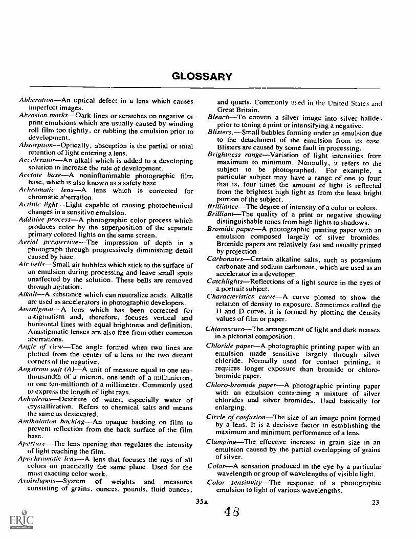
GLOSSARY
AbberationAn optical defect in a lens which causesimperfect images.
Abrasion marksDark lines or scratches on negative orprint emulsions which are usually caused by windingroll film too tightly, or rubbing the emulsion prior todevelopment.
AbsorptionOptically, absorption is the partial or totalretention of light entering a lens.
AcceleratorAn alkali which is added to a developingsolution to increase the rate of development.
Acetate baseA noninfianimable photographic filmbase, which is also known as a safety base.
Achromatic lensA lens which is comected forchromatic a',erration.
Actink lightLight capable of causing photochemicalchanges in a sensitive emulsion.
Additive processA photographic color process whichproduces color by the superposition of the separateprimary colored lights on the same screen.
Aerial perspectiveThe impression of depth in aphotograph through progressively diminishing detailcaused by haze.
Air bellsSmall air bubblzs which stick to the surface ofan emulsion during processing and leave small spotsunaffected by the solution. These bells are removedthrough agitation.
AlkaliA substance which can neutralize acids. Alkalisare used as accelerators in photographic developers.
AnastignuttA lens which has been corrected forastigmatism and, therefore, focuses vertical andhorizontal lines with equal brightness and definition.Anastigmatic lenses are also free from other commonaberrations.
Angle af viewThe angle formed when two lines areplotted from the center of a lens to the two distantcorners of the negative.
Angstrom unit (A)A unit of measure equal to one ten-thousandth of a micron, one-tenth of a millimicron,or one ten-millionth of a millimeter. Commonly usedto express the length of light rays.
Anhydrous--Destitute of water, especially water ofcrystallization. Refers to chemical salts and meansthe same as desiccated.
Antilutlation backingAn opaque backing on film toprevent reflection from the back surface of the filmbase.
ApertureThe lens opening that regulates the intensityof light reaching the film.
Apochromatic lensA lens that focuses the rays of allcolors on practically the same plane. Used for themost exacting color work.
AvoirdupoisSystem of weights and measuresconsisting of grains, ounces, pounds, fluid ounces,
and quarts. Commonly used in the United States andGreat Britain.
BleachTo convert a silver image into silver halidesprior to toning a print or intensifying a negative.
Blisters.Small bubbles forming under an emulsion dueto the detachment of the emulsion from its base.Blisters are caused by some fault in processing.
Brightness rangeVariation of light intensities frommaximum to minimum. Normally, it refers to thesubject to be photographed. For example, aparticular subject may have a range of one to four;that is, four times the amount of light is reflectedfrom the brightest high light as from the least brightportion of the subject .
BrillianceThe degree of intensity of a color or colors.BrilliantThe quality of a print or negative showing
distinguishable tones from high lights to shadows.Bromide paperA photographic printing paper with an
emulsion composed largely of silver bromides.Bromide papers are relatively fast and usually printedby projection.
CarbonatesCertain alkaline salts, such as potassiumcarbonate and sodium carbonate, which are used as anaccelerator in a developer.
CatchlightsReflections of a light source in the eyes ofa portrait subject.
Characteristics curveA curve plotted to show therelation of density to exposure. Sometimes called theH and D curve, it is formed by plotting the densityvalues of film or paper.
ChiaroscuroThe arrangement of light and dark massesin a pictorial composition.
Chloride paperA photographic printing paper with anemulsion made sensitive largely through silverchloride. Normally used for contact printing, itrequires longer exposure than bromide or chloro-bromide paper.
Chloro-bromide paperA photographic printing paperwith an emulsion containing a mixture of silverchlorides and silver bromides. Used basically forenlarging.
Circle of confusionThe size of an image point formedby a lens. It is a decisive factor in establishing themaximum and minimum performance of a lens.
ClumpingThe effective increase in grain size in anemulsion caused by the partial overlapping of grainsof silver.
ColorA sensation produced in the eye by a particularwavelength or group of wavelengths of visible light.
Color sensitivityThe response of a photographicemulsion to light of various wavelengths.
35a 23
48
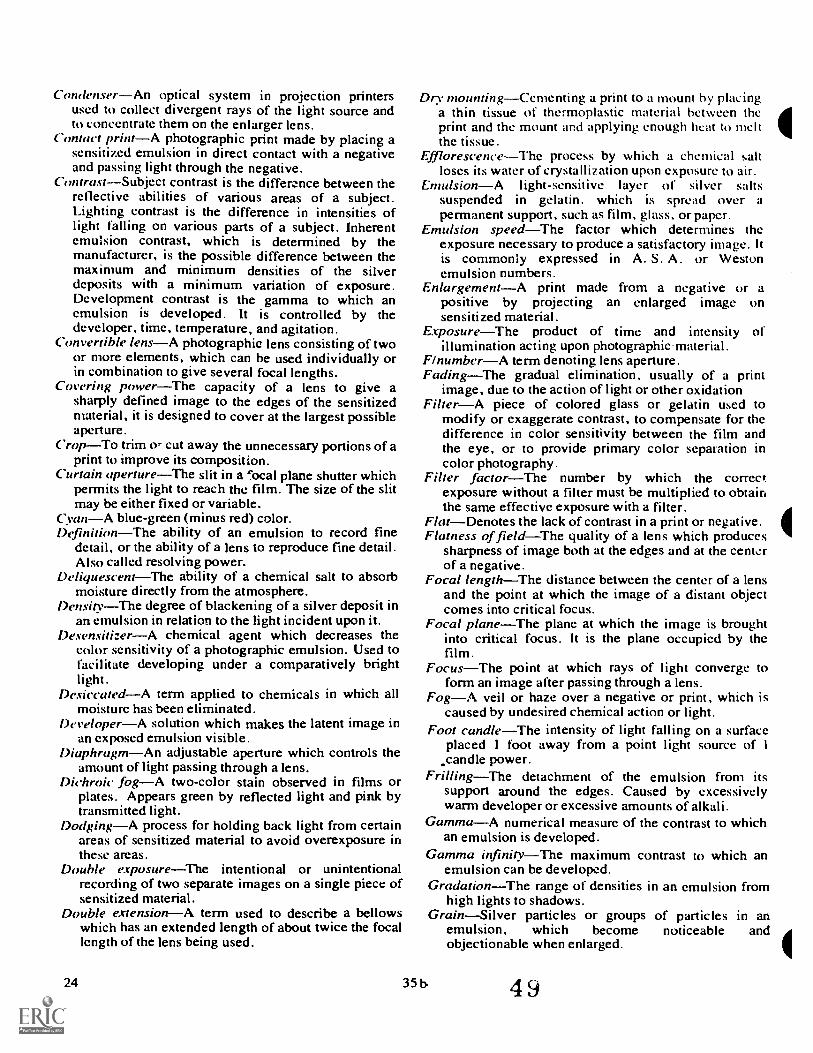
CorulenserAn optical system in projection printersused to collect divergent rays of the light source andto concentrate them on the enlarger lens.
Contact printA photographic print made by placing asensitized emulsion in direct contact with a negativeand passing light through the negative.
ContrastSubject contrast is the difference between thereflective abilities of various areas of a subject.Lighting contrast is the difference in intensities oflight falling on various parts of a subject. Inherentemulsion contrast, which is determined by themanufacturer, is the possible difference between themaximum and minimum densities of the silverdeposits with a minimum variation of exposure.Development contrast is the gamma to which anemulsion is developed. It is controlled by thedeveloper, time, temperature, and agitation.
Convertible lensA photographic lens consisting of twoor more elements, which can be used individually orin combination to give several focal lengths.
Covering powerThe capacity of a lens to give asharply defined image to the edges of the sensitizedmaterial, it is designed to cover at the largest possibleaperture.
CropTo trim o- cut away the unnecessary portions of aprint to improve its composition.
Curtain apertureThe slit in a ':ocal plane shutter whichpermits the light to reach the film. The size of the slitmay be either fixed or variable.
CyanA blue-green (minus red) color.DefinitionThe ability of an emulsion to record fine
detail, or the ability of a lens to reproduce fine detail.Also called resolving power.
DeliquescentThe ability of a chemical salt to absorbmoisture directly from the atmosphere.
DensityThe degree of blackening of a silver deposit inan emulsion in relation to the light incident upon it.
DesensitizerA chemical agent which decreases thecolor sensitivity of a photographic emulsion. Used tofacilitate developing under a comparatively brightlight.
DesiccatedA term applied to chemicals in which allmoisture has been eliminated.
DeveloperA solution which makes the latent image inan exposed emulsion visible.
DiaphragmAn adjustable aperture which controls theamount of light passing through a lens.
Dichroic fogA two-color stain observed in films orplates. Appears green by reflected light and pink bytransmitted light.
DodgingA process for holding back light from certainareas of sensitized material to avoid overexposure inthese arcas.
Double exposureThe intentional or unintentionalrecording of two separate images on a single piece ofsensitized material.
Double extensionA term used to describe a bellowswhich has an extended length of about twice the focallength of the lens being used.
Dry mountingCementing a print to a mount by placinga thin tissue of thermoplastic material between theprint and the mount and applying enough heat to meltthe tissue.
EfflorescenceThe process by which a chemical saltloses its water of crystallization upon exposure to air.
EmulsionA light-sensitive layer of silver saltssuspended in gelatin, which is spread over a
permanent support, such as film, glass, or paper.Emulsion speedThe factor which determines the
exposure necessary to produce a satisfactory image. Itis commonly expressed in A. S. A. or Westonemulsion numbers.
EnlargementA print made from a negative or apositive by projecting an enlarged image onsensitized material.
ExposureThe product of time and intensity ofillumination acting upon photographicmaterial.
FlnumberA term denoting lens aperture.FadingThe gradual elimination, usually of a print
image, due to the action of light or other oxidationFilterA piece of colored glass or gelatin used to
modify or exaggerate contrast, to compensate for thedifference in color sensitivity between the film andthe eye, or to provide primary color separation incolor photography.
Filter factorThe number by which the correctexposure without a filter must be multiplied to obtainthe same effective exposure with a filter.
FlatDenotes the lack of contrast in a print or negative.Flatness of fieldThe quality of a lens which produces
sharpness of image both at the edges and at the centerof a negative.
Focal lengthThe distance between the center of a lensand the point at which the image of a distant objectcomes into critical focus.
Foca/ planeThe plane at which the image is broughtinto critical focus. It is the plane occupied by thefilm.
FocusThe point at which rays of light converge toform an image after passing through a lens.
FogA veil or haze over a negative or print, which iscaused by undesired chemical action or light.
Foot candleThe intensity of light falling on a surfaceplaced 1 foot away from a point light source of 1
candle power.FrillingThe detachment of the emulsion from its
support around the edges. Caused by excessivelywarm developer or excessive amounts of alkali.
GammaA numerical measure of the contrast to whichan emulsion is developed.
Gamma infinityThe maximum contrast to which anemulsion can be developed.
GradationThe range of densities in an emulsion fromhigh lights to shadows.
GrainSilver particles or groups of particles in anemulsion, which become noticeable andobjectionable when enlarged.
24 35 b. 4 9
Gray scaleA series of densities in definite stepsranging from white to black. Same as sensitometricstrip.
Ilalation--A blurred effect, resembling a halo, usuallyoccurring around bright objects. Caused by reflectionof light rays from the back of the negative material.
HalftonesMiddle tones lying between shadows andhigh lights.
Halides (or Italoids)Binary compounds containing anyof the following elements: chlorine, bromine, iodine,fluorine.
Halogenlodine, fluorine, chlorine, and bromine areknown as halogens.
tiardDenotes excessive contrast.High lightsThe brightest parts of a subject, which are
represented by the denser parts of a negative and thelight gray and white tones of a print.
HyperfOcal distanceThe distance from the lens to thenearest plane in sharp focus, when the lens is focusedat infinity.
ImbibitionThe act of absorbing. The process of dyetransfer in the washoff relief process of making colorprints.
IncandescentGlowing with heat, such as the tungstenfilament in an incandescent lamp.
Infinity--A distance so far removed from an observerthat the rays of light reflected to a lens from a point atthat distance may be regarded as parallel. A distancesetting on a camera focusing scale, beyond which allobjects are in focus.
Latent imageThe invisible image formed in anemulsion by exposure to light. It is rendered visibleby the process of development.
LatitudeExposure latitude is the quality of a film,plate, or paper which allows variation in exposurewithout damaging the image quality. Developmentla' T ude is the allowable variation in therecommended developing time without noticeabledifferences in contrast or density.
Lumen--A measurement of light, equal to the amount oflight falling on a foot-square surface which is 1 footaway from a point light source of 1 candlepower.
MagentaA reddish-blue (minus green) color.MaskA negative image of a color transparency, of thin
but varying density, used to key down colorintensities of a color transparency.
MaskingA corrective measure used in three-colorphotography to compensate for the spectralabsorptive deficiencies in pigments, dyes, andemulsions. This compensation improves the accuracyor color reproduction.
Matrix--A gelatin relief image used in the washoff reliefprocess of color photography.
MonochromaticA single color.Nitrate hase--A photographic film base composed of
cellulose nitrate. Highly inflammable.Oltfecth.eA term applied to a lens that is used to form
a real image of an object.
OpacityResistance of a material to the transmission oflight.
OpaqueA condition of an object which prevents thetransmission of visible light.
OxidationThe process of combining a substance withoxygen.
PerspectiveThe illusion of' three dimensions createdon a flat surface.
PreservativeA chemical. such as sodium sulfite,which, when added to a developing solution. tends toprolong its life.
Pritnary colorAny one of threc components of whitelightblue, green, and red.
ReflectionThe diversion of light from any surface.Resolving powerThe ability of an emukion to record
fine detail, or of a lens to reproduce fine detail.RestrainerAny chemical. such as potassium bromide,
which, when added to a developing solution, has thepower of slowing down the developing action andmaking it more selective.
ReticulationThe formation of a wrinkled or leather-like surface on a processed emulsion due to excessiveexpansion or retraction of the gelatin caused bytemperature changes or chemical action.
ReversalA process by which a negative image isconverted to a positive. A negative is developed,reexposed, bleached, and redeveloped to form apositive.
ScaleScale is the ratio of a linear dimension in thesubject to the corresponding dimension in thephotograph.
Secondary colorsColors formed by the combination oftwo primary colors. Yellow, magenta, and cyan arethe secondary colors.
SensitizerDyes used in the manufacture ofphotographic emulsions. Sensitizers can be of twotypes: one to increase the speed of an emulsion; theother to increase its color sensitivity.
SensitometerA device for producing on sensitizedmaterial a series of exposures increasing at a definiteratio. Such a series is needed in studying thecharacteristics of an emulsion.
Sensitometric stripA series of densities in definitesteps ranging from white to black.
Separation negativesThree negatives, each of whichrecords one of the three primary colorsblue, green,and red.
Time-gamma-temperature curveA curve ofdeveloping time plotted against developed contrast orgamma. The contrast for any given time may be readdirectly from the curve, or vice versa. The curveapplies only to one particular developer andemulsion.
ToneIn photography, this usually applies to the colorof a photographic image or, incorrectly, to anydistinguishable shade of gray.
ToningA method for changing the color or tone of animage by chemical action.
35 c 25
0 Li

TransmissionThe ratio of light passed through anobject to the light falling on it.
SoftA term used to describe prints and negatives withlow contrast.
Stock solutionPhotographic solution in concentratedform and intended to be diluted for use.
26
Subtractive processA process in color photography,using the colors magenta, cyan, and yellm.Contrasted with the additive color process.
Working solutionA photographic solution which isready for use.
36
51
CHAPTER 1
Reference:
Answers for Exercises
001 I . a. Abilities.b. Five; Air Force specialty code (AFSC).c. Five; 1helper, 3semi-skilled, 5skilled, 7
journeyman, 7advanced, 9superintendent.002 I . b. c. d.
003 - I. I. b, 2. a, 3. e, 4. d, 5. c.
004 I . 3 level.004 2. 5 level.0(14 3. 7 level.
005 I . Training to qualify skilled airmen who are retraining into adifferent career field or career ladder; contract specialtraining: ATC Special Resident Training
005 2. General prerequisites for qualifying for formal training;retainability requirements after training has been received;reporting instructions; and general informaticn on ATCcourses. Volume 2 contains course announcements.
006 I . Field evaluation visit; direct correspondence questionnaire;and job performance evaluations. The ability of graduates toperform required duties; how well graduates remember whatthey are taught; whether the STS or school needs to bechanged: and whether more evaluation is needed in specificcareer field areas.
a.h.C.
d.c.
a.h.c.
h.C.
d.
CHAPTER 2
Classified.Unclassified.For Official Use Only.Unclassified but of possible intelligence value.
Top Secret.Secret.Confidential.Confidential.For Official Use Only.
Messenger.Encrypted radio message.Registered mail.
Poor physical sccurity.Poor planning.Awe of rank.Talk around, paraphrasing, incomplete references,self-made reference system.
011 I . To prevent the disclosure of information containingintelligence indicators that can be used to degradeoperational effectiveness.
01 I 2. As a photographer involved in documenting varioushappenings around the base, some of which may besensitive, discussing these happenings in public could resultin the release of possible intelligence indicators.
Oi I - 3. Operations, procedures, and communications.
CHAPTER 3
012 1. a, d, e.
013 1. a, c, d, f.
014 - 1. a. c.
015 I. Crack thc valve; reclose valve; attach regulator: check thcadjusting screw on thc regulator and make certain that it isreleased before opening thc cylinder valve.
016 I. b. d. e. f.
CHAPTER 4
017 I. When properly completed, thc work request becomes thcsource for all pertinent information about a photographicassignment including thc cost of materials and manpowerrequired.
017 2. Laboratory administrative personnel.017 3. Supervisors.
018 I. To provide information to lab administrative personnel onall work requests received by the photo lab that arc beingworked on or have becn completed and filed.
018 2. Work request number; requester's organi7ation or officesymbol; date received; description of work; date completed.
018 3. To locate and determine the status of all work requests beingaccomplished or already completed.
018a I. To evaluate the manning requirements of your lab.018a - 2. From work requests.018a 3. C ...ide exposures; inside exposures; copy camera
exposures; black-and-white negatives delivered: colornegatives delivered; contact prints: and production prints
019 I . Locate AF Form 80: find the proper file category on theForm 80; look through the files until you find the filecategory you arc looking for. Look through the file categoryfolder to locate the correspondence. Items in thc file arefiled by date with the most recent item in the front of thefolder.
020 I. a. Confidential.b. 12-50.c. don't.
021 I . a. True.c. Truc.
022 - I. a. 10B1-6-3-1.b. 10B1-7-2-21.c. Camera. copying still picture camera. P/N 01-1392.
Model SFS-35 (sickles).d. Ground camera. press. Type C-6 (Gralles ).
023 1. a.b.c.d.e.f.
g-
Properly and uniformly.Instructions.95.Operating instruction.Task.Manufacturer.Bulletin.
37 27
52

024 I. a, c, e.
025 - I . a. Locally.b. Base (acetate).c. Alpha suffix.d. Negative numbers, calendar year, exposing unit, and
security classification.
02(1 I h. True.d. True.
027 - I. Original negatives properly lettered 1AW AFR 95-4;captions (AF Form 397 or 398); a high-quality 4x5-inch (10x 12em) print of each negative.
027 - 2. Contact.
28
028 1. e, g, h, j.028 2. a. Mental.
b. Federal.c. Regulations.d. Unpublished.c. Civil; criminal.
029 - I. To determine the cause in the event that equipment is lost,damaged, or destroyed.
029 2. A Statement ot Charges authorires the Air Force to takemoney owed out of your pay.
029 3. The commander appoints an investigating officer whoconducts the Report of Survey.
029 4. DD Form 1131, Cash Collection Voucher; DD Form 2(X),Repot( of Survey.
38
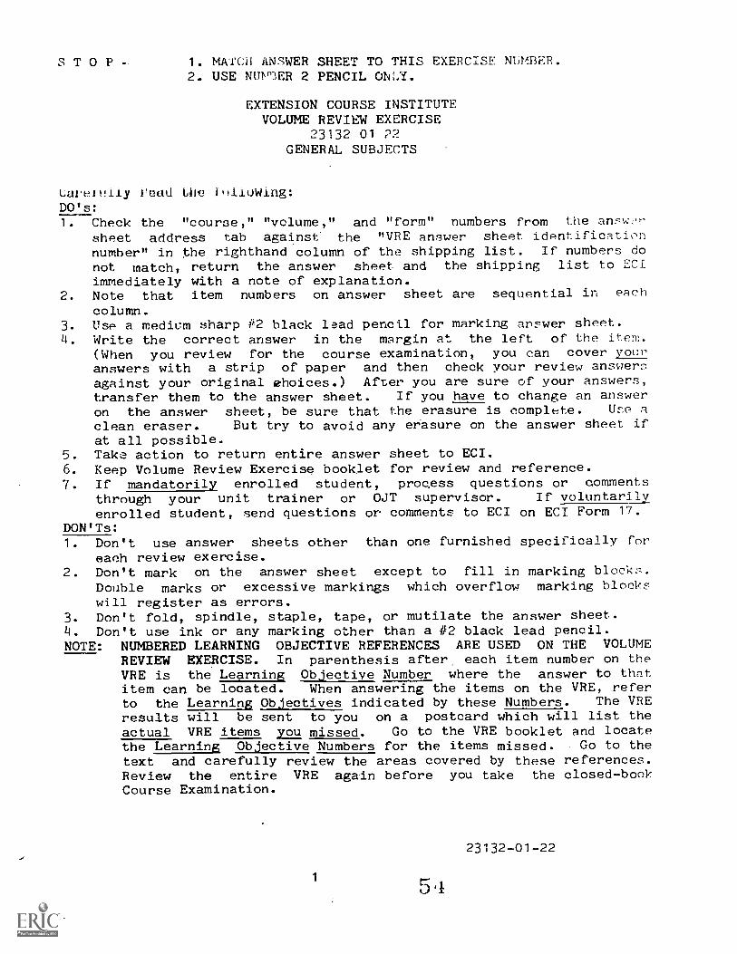
S T 0 P - 1. MArCH ANSWER SHEET TO THIS EXERCISE NUMBER.2. USE NUVrIER 2 PENCIL ONLY.
EXTENSION COURSE INSTITUTEVOLUME REVIEW EXERCISE
23132 01 22GENERAL SUBJECTS
Larelutly Vedd iHiluwing:DO's:1. Check the "course," "volume," and "form" numbers from the answn
sheet address tab against. the "VRE answer sheet identificationnumber" in the righthand column of the shipping list. If numbers donot match, return the answer sheet and the shipping list to ECIimmediately with a note of explanation.
2. Note that item numbers on answer sheet are sequential in each
column.3. LISP a medium sharp #2 black lead pencil for marking answer sheet.I. Write the correct answer in the margin at the left of the item.
(When you review for the course examination, you can cover youranswers with a strip of paper and then check your review answersagainst your original choices.) After you are sure of your answers,transfer them to the answer sheet. If you have to change an answeron the answer sheet, be sure that the erasure is compl(Ite. Une a
clean eraser. But try to avoid any erasure on the answer sheet ifat all possible.
5. Take action to return entire answer sheet to ECI.6. Keep Volume Review Exercise booklet for review and reference.7. If mandatorily enrolled student, progess questions or comments
through your unit trainer or OJT supervisor. If voluntarilyenrolled student, send questions or comments to ECI on ECI Form 17.
DON'Ts:1. Don't use answer sheets other than one furnished specifically for
each review exercise.2. Don't mark on the answer sheet except to fill in marking blockF,.
Double marks or excessive markings which overflow marking blockswill register as errors.
3. Don't fold, spindle, staple, tape, or mutilate the answer sheet.4. Don't use ink or any marking other than a #2 black lead pencil.NOTE: NUMBERED LEARNING OBJECTIVE REFERENCES ARE USED ON THE VOLUME
REVIEW EXERCISE. In parenthesis after each item number on theVRE is the Learning Objective Number where the answer to thatitem can be located. When answering the items on the VRE, referto the Learning Objectives indicated by these Numbers. The VREresults will be sent to you on a postcard which will list theactual VRE items you missed. Go to the VRE booklet and locatethe Learning Objective Numbers for the items missed. Go to thetext and carefully review the areas covered by these references.Review the entire VRE again before you take the closed-bookCourse Examination.
1
5 4
23132-01-22

MULTIPLE CHOICE
1. (001) What AFSC will 'you be awarled after you complete thi,: CDC?
a. 23112.b. 23132.
c. 23152.d. 23192.
2. (001) Which one of the following statements regarding the MilitaryClassification System is true?
a. The specialty numbers are the same for each military branch.b. Each position is identified by a six-digit number.c. Positions are grouped according to common knowledge, skills,
and abilities.d. Each duty is classified into a specialty career field known
as a Military Specialty Code.
3. (002) Which one of the following is not mandatory for upgradeto the 3 level?
a. High school chemistry course.b. Normal color vision.c. Experience in still photography.d. Completion of this CDC.
4. (003) When you successfully complete your 3-level training, youwill
a. start working toward your 5 level.b. be promoted to senior airman.c. begin training as a supervisor.d. complete your on-the-job training.
5. (003) The major difference between AFSC 23132 ad 23152 is thatthe latter has
a. more time in grade.b. fewer supervisory responsibilities.c. received more management training.d. been to an advanced photo school.
6. (004) As a 3-level photographer, you would be expected to doall of the following except
a. perform pictorial research.b. plan and schedule work assignment.c. employ visual evaluation.d. mix finishing solutions.
7. (004) What Air Force regulation contains specialty descriptions?
a. AFR 12-50. c. AFR 50-5.b. AFR 39-1. d. AFR 95-4.
23132-01-22
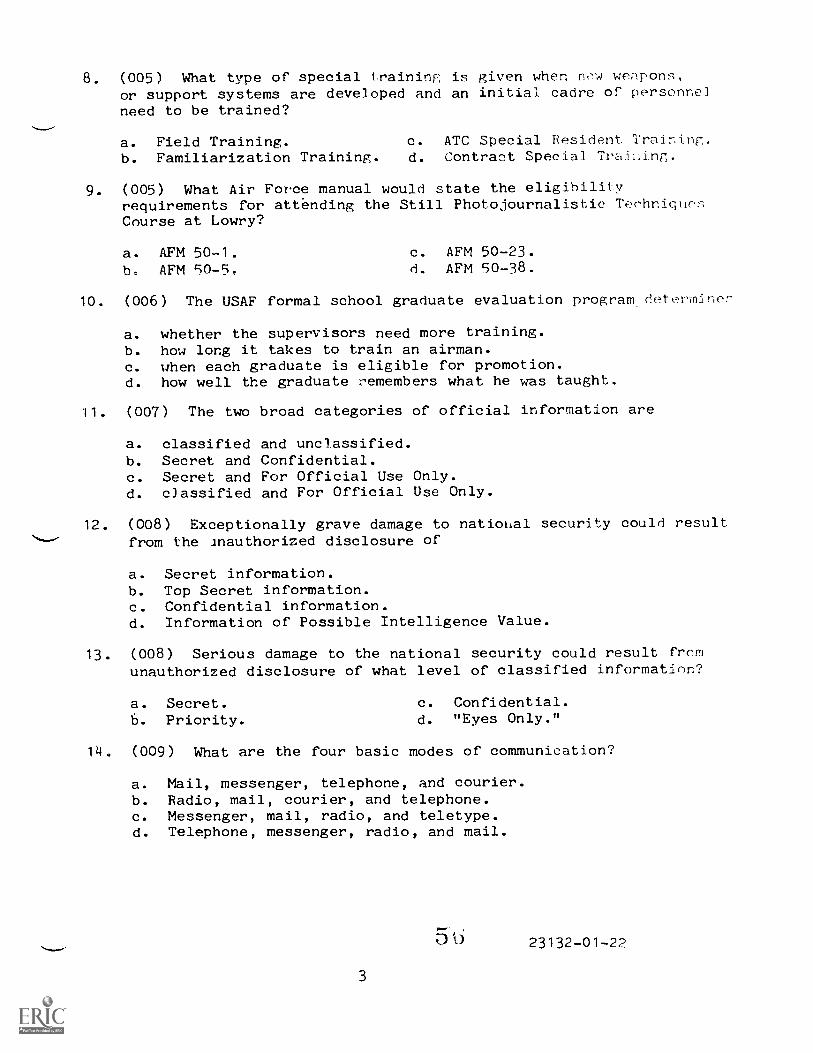
8. (005) What type of special traininp; is given when new werlpons,or support systems are developed and an initial cadre of personnelneed to be trained?
a. Field Training. c. ATC Special Resident Training.b. Familiarization Training. d. Contract Special Training.
9. (005) What Air Force manual would state the eligibilityrequirements for attending the Still Photojournalistic TeehniqueCourse at Lowry?
a. AFM 50-1. c. AFM 50-23.h. AFM 90-5, d. AFM 50-38.
10. (006) The USAF formal school graduate evaluation program.determner-
a. whether the supervisors need more training.b. how long it takes to train an airman.c. when each graduate is eligible for promotion.d. how well the graduate remembers what he was taught.
11. (007) The two broad categories of official information are
a. classified and unclassified.b. Secret and Confidential.c. Secret and For Official Use Only.d. c3assified and For Official Use Only.
12. (008) Exceptionally grave damage to national security could resultfrom the inauthorized disclosure of
a. Secret information.b. Top Secret information.c. Confidential information.d. Information of Possible Intelligence Value.
13. (008) Serious damage to the national security could result frcmunauthorized disclosure of what level of classified information?
a. Secret.b. Priority.
c. Confidential.d. "Eyes Only."
14. (009) What are the four basic modes of communication?
a. Mail, messenger, telephone, and courier.b. Radio, mail, courier, and telephone.c. Messenger, mail, radio, and teletype.d. Telephone, messenger, radio, and mail.
5 b 23132-01-22
15. (009) The guarantee that a messag will reach the right: personis known as
a. speed. c. reliability.b. security. d. protection.
16. (010) If you try to get information across hy chant-Ling the words,you are guilty of
a. paraphrasing. c. self-made disclosure.b. incomplete reference. d. talk-around.
17. (011) The prevention of disclosure of information containingintelligence inaicators that can be used to degrade operationa2effectiveness is the purpose of which security program?
a. TRANSEC.b. COMSEC.
c. TELSEC.d. OPSEC.
18. (012) Which one of the following is an approved operating practicyin a photographic n-cility?
a. Remove rings and watches before operating machines.b. Use tinfoil as a short-term fuse.c. Place a timer on a rubber mat in a processing sink.d. Overload circuits when you need more power.
19. (012) Why should you remove your rings and watches before youoperate a processing machine?
a. To keep from losing them in the solutions.b. To reduce the possibility of being shocked.c. To keep from scratching the film.d. To allow you to reach into small spaces.
20. (013) Which one of the following is the least dangerous foridentifying an unknown chemical?
a. Taste a drop of the chemistry from your fingertip.b. Test the chemical by adding water without stirring.,c. Mix the chemical with a known ingredient and note the reaction.d. Cautiously sniff the bottle held at a distance from your nose.
21. (013) Which one of the following is true regarding propr,r chemicalsafety?
a. Induce vomiting if a photodeveloper chemical is swallowed.b. Wash chemicals from your eyes with as little water as possible.c. Wear a respirator when you mix powdered chemicals.d. Be sure that the chemical mixing room vents are closed tightly
to prevent fumes from escaping.
4 5 r23132-01-22
22. (014) Which one of the followin r. stat ments is true doncrni,compressed nitrogen gas?
a. Nitrogen is oderless, tasteless, aud colorless.b. Nitrogen cannot cause asphyxiation.c. Close all windows and doors before you use compresned nitrcy.d. Never chain nitrogen cylinders to Ale
23. (014) What would be the most probable reaction if the top ofa nitrogen cylinder were cracked durini7 handling?
a. It would burst into flames.b. The escaping gas would produce insf-.ant freezing.c. You would start vomiting after inhaling the noxious fumes.d. The cylinder could become a deadly projectile.
24. (015) What is the first step in connecting a new gas cylinderto your agitation system?
a. Release the handwheel. c. Open the valve slightly.b. Open the regulator. d. Adjust the union.
25. (016) When you knowingly violate a safety rule, which principleof mechanical safety are you neglecting?
a. Alertness.b. Planning.
c. Self-discipline.d. Keeping physicallyt fit.
;16. (017) Part II of AF Form 833 provides spaces for recording the
a. workload data.b. requester's name and organization.c. justifica:Aon for the-work to bn done.d. work request nurber.
27. (017) Part II of AF Form 833 should he completed properly becauF-it
a. is the sole justification for the job to be done.h. is the source for photo lab operating costs.c. is the photographer's specific instructions.d. gives the requesters name, organization, and phone numLer.
28. (018) The work request log can be used by laboratoryadministrative personnel to
a. record operating costs.b. locate filed negatives.c. determine the job to be done.d. schedule work.
23132-01-22
29. (018) Answering inquiries on the :tatur s oneof the responsibilities of te
a. photographers.h. laboratory administrative per: Tinel.c. darkroom personnel.d. requester.
30. (0'
shot
The AF Fbe ke
, Files Maintnance and Dispositjon Plan,
a. in e'Ar6ry front of the first filo drawer.b. c.Tthe b,oratory manager's desk.c. ::;bif top o .t1:'.' filing cabinet.d,-- on the work order control desk.
31. (019) General correspondence is filed by
a. date, with the most recent material at the front of the folder.b. date, with the most recent material in the back of the folher.c. subject, alphabetically.d. date, alphabetically.
32. (020) The photo lab negative file may contain negatives witha security classification, not higher than
a. Secret.b. Confidential.
c.
d.
Top Secret.Crypto.
33. (020) Which of the following should be fA.led?
a. Copy negatives that satisfy tne needs of one user.b. Negatives of practice assignments.c. Pictures used for a damage report.d. Extra negatives not suitable for printing.
34. (020) Negatives used for a damage report should be kept on filefor at least
a. 60 days.b. 90 days.
c. 120 days.d. 180 days.
35. (021) Which of the following technical orders contains informationand instructions on safety and preventive maintenance?
a. Methods and Procedures Technical Order (MPTO).b. Time Compliance Technical Order (TCTO).c. Technical Order Index.d. Numerical Index Technical Order.
6 95
23132-01-

36. (022) Which one of the following Technical Order indexes wouldbe used to locate a technical order that has 1-)en assigned a newnnmber?
a. TO 0-1-01, Numerical Index and Reqoirement Table.b. TO 0-2-1, Alphabetical Index.c. TO 0-4-1, Cross Reference Tables index.d. 70 0-1-10, Photographic Equipment, Supplies, and Sensitized
Materials.
37. (022) Which of the following numbers identifies the technicalorder category -,overing photographic equipment?
a. 5.b. 10.
c. 30.d. 50.
38. (023) Which one of the following series of Air Force Regulationsdeals with audiovishal systems?
a. 5.
b. 30.
c. 95.d. 100.
39. (023) Which one of the following statements is true regardingoperating instruct4ons?
a. Operating instructions are rigid in format.b. Operating instructions do not hav to be numbered.c. Operting instructions provide.general information about a
task.
d. Operating instructions indicate who is responsible forperformance of the task.
40. (023) Which one of the following statements is true regardingcommercial publications?
a. Commercial publications are not used hy photographiclaboratories.
b. Commercial publications give only general information aboutitems of equipment and photographic products.
c. Commercial publications should be discarded after they areread.
d. Commercial publications are normally furnished bymanufacturer's to purchasers of their products.
41, (024) The distinction between record and nonrecord photogranhyis
a. often subjective.b. defined in AFR 95-7.c. always determined by the lab chief.d. unnecessary at the local level.
23132-01-22
7
42. (024) Guidelines for determining 1-1a.t qualifie: as rcor,Iphotography are covered in
a. AFR 95-1. c. AFR 95-6.b. AFR 95-3. d. AFR 95-7.
43. (025) Which of the following Air Force regulation:-; tz7, the
guideline for lettering and captio:;ing still photography?
a. AFR 39-1. c. AFR 95-4.b. AFR 50-5. d. AFR 127-101.
44. (025) Which of the following is not included as part 7)f the
negative lettering information?
a.
b.
Negative number.Calendar year.
c.
d.
Security classification.Photographer's name.
45. (026) Which of the following statements is true regardingcaptioning and identifying prints?
a. AF Form 398 must be used to identify all photographF,.b. The caption must include the photographer's name.c. he best method for identifying prints is ink stamping.d. Prints should be identified by overprinting on the front
side.
46. (026) Each negative that is considered to be record photographymust be
a.
b.
stamped.published.
c. printed.d. captioned.
47. (027) What three things must be included when forwarding a roeordphotography package to the USAF Central Still PhotographicLaboratory?
a. Original negative, caption, and cover story,b. Caption, contact print, and model release.c. Original negative, caption, and high quality print.d. Model release, high quality printing, and duplicate nega'iv;-.
48. (027) The Air Force regulation that contains dotailed and npecillinstructions on the submission of record photography to he U::11AP
Central Still Photographic Laboratory is
a. AFR 95-1. c. AFR 95-7.b. AFR 95-4. d. AFR 95-10.
8 6i23132-01-22

49. (028) The symbol "0" on a printed dcument, indicates tithe document is
b.
71assified.controlled.
C. cl.trtered.C. ccpyrighted.
1)0. (W8) Which of th following subject can you legally nopy 1,)the same size and in color?
a. Coins. c. Driver', licenses.b. Immigration papers. d. Paper money.
23132-01-22
9
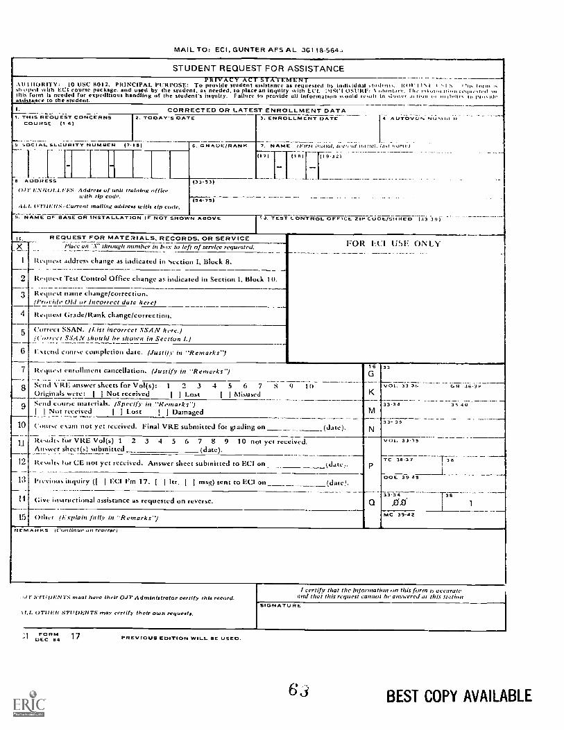
MAIL TO: ECI, GUNTER AFS AL 36118.564,i
STUDENT REQUEST FOR ASSISTANCE_.. .
..s.I.IIIIORITY: 10 USC g012. PRINCIPAL PURPOSE: To provide student assistance as requested bY indisidoal stiMvnts. Rol' i I i , `I N , ',shwed with EC1 course package. nd used by the student, as needed, to place an inquiry with E.('I. ilSt'l °SURF: oiontarv. ril.. ,0,,,,.,O..., ge,,,,,,r,o ,,.,oi 1.0.t. ii, pl., idethis form is needed for expeditious handling of the student's inquiry. Failure to provide all Information ',maid resiiii in s:Osser .11 .iOti vl iI l
assistance to the student.I. CORRECTED OR LATEST ENROLLMENT DATA
. .._ _I. THIS REQUEST CONCERNSCOURSE (1'6)
2. TODAY'S DATE 3. ENROLLMENT DATE 4 AUTOVON Nu,(Lit ii
5 50C I A L SLCURITY NUMUER PAS) 6. GRADE/RANK 7. NAME (FIr,t i taIni, IIer,1,1 INS( la:, 1.,1st-5,711S
111
... .. _ . __ ....._.
(1-9732I
8 ADDRESS
0.P.I.:NUtzl.l.t. Es Address Of nnit training offkewith zip code.
.11.1. OTtIVIIS-Current mulling address with zip code.
(33-53)
0 4-75)
9. NAME OF BASE OR INSTALLATION IF NOT SHOWN ABOVE 13. TEST LONTROL OFFICE ZIP CDOE/SHRED (33 3 9 )
it. REQUEST FOR MATERIALS. RECORDS. OR SERVICEF OR LC 1 U SE ONLYX Place an 'X' through number in box to left of service requested.
1 Request address change as indicated in Section I, Block 8.
2 Itcplest 'rest Control Office change as indicated in Section I. Block 10.
3_
Request name change/correction.(Proride Old or Incorrect data here)
4 Request Grade/Rank change/correction.
5 Correct SSAN. (List incorrect SSA N here.)(Correct SSA N should be shon'n in Section I.)
_
6-
r. xtceld course completion date. (Justify' in "Remarks-)
7 Request enrollment cancellation. (Justify in "Remarks-)16G
K
M
33
77Ci7. 717:: ..;ii-Ii-
33-34 35-40
8 -semi vitt: answer sheets for Vol(s): 1 2 3 4 5 4 7 S 9 10Originals were: 1 i Not received I I Lost 1 I Misused
9 Send course materials. (Specify in "Remarks-)I I Not received 1 I t.ost I I Damaged
10 Cmirse exam not yet received. Final VRE submitted for grading on (date), N33- 35
_...
u .
Results tor VRE Vol(s) 1 2 3 4 5 6 7 8 9 10 not yct received.Answer sheet (s) submitted (date).
Q
VOI.. 33.35
'-.7-a- -----.7-3.-12 Results tor CE not yet received. Answer sheet submitted to F.CI on (date'...36-37
13 Previous inquiry (I I ECI Fin 17. I I hr. 1 I msg) sent to ECI on. (d, .atel
DOE 39 45
ii Give instructional assistance as requested on reverse.33.34
00. 1
15 Other (Explain IWO, in "Rem arks-) MC 19-42
fieMAI1 KS (Continue an reverse)
, JI STU Ilk NTS Must twee their C.M7' Administrator certify this record.
(yrit Rif STUDENTS may certify their own requests.
I certify that thc information on this form is accurateand that this request cannot be answered at this station
SIGNATURE
"RM 17DEC 84 PREVIOUS EDITION WILL BE USED.
BEST COPY AVAILABLE
REQUEST FOR INSTRUCTOR ASSISTANCENO IT.: Questions or comm en ts rela ting to the accuracy or currency of subject matter should be forwarded dire,- tly ro pupal ini-zagency. For an immediate response to these questions, call or write the course author dilectly, using the A MO VON mint t
address in the preface of each volume. All other inquiries concerning the course should be forwarded to ECI.MY QUESTION IS:
VRE ITEM QUESTIONED:
COURSE NO
VOLUME NO
VRE FORM NO
VRE ITF.M NO
ANSWER YOU CHOSE(Letter)
HAS VRE ANSWER SHEET BEENSUBMITTED FOR GRADING?
Ci YES 0 NO
REFERENCE
(Textual reference tor the answer I chosecon be found os shown below.)
IN VOLUME NO
ON PAGE NO
IN LI LEFT U RIGHT COLUMNLINES THROUGH
REMARKS
ADDITIONAL FORMS 17 available from trainers, OJT and EducationOffices, and EC!. Course workbooks have a Form 17 printed on the last ia e.
ECI FORM 17. DEC 8 4 (Reverse)
23132 02 7905
CDC 23132
APPRENTICE STILL PHOTOGRAPHICSPECIALIST
(AFSC 23132)
Volume 2
Still Photographic Fundamentals
Extension Course InstituteAir Training Command
Prepared byMSgt Curtis Mayne
andMSgt Jay Perry
3430th Technical Training GroupUSAF School of Applied Aerospace Sciences (ATC)
Lowry AFB, Colorado 80230
Reviewed byJohn Zimmerman, Education SpecialistExtension Course Institute (ATC/AU)
Gunter AFS, Alabama 36118
PREPARED BY3430TH TECHNICAL TRAINING GROUP
USAF SCHOOL OF APPLIED AEROSPACE SCIENCES (ATC)LOWRY AIR FORCE BASE, COLORADO
EXTENSION COURSE INSTITUTE, GUNTER AIR FORCE STATION, ALABAMA
THIS PUBLICATION HAS BEEN REVIEWED AND APPROVED BY COMPETENT PERSONNEL OF THE PREPARING COMMANDIN ACCORDANCE WITH CURRENT DIRECTIVES ON DOCTRINE, POLICY, ESSENTIALITY, PROeRIETY, AND QUALITY.
6 6
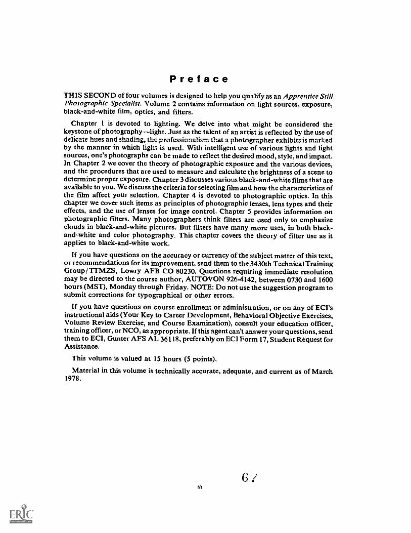
PrefaceTHIS SECOND of four volumes is designed to help you qualify as an Apprentice StillPhotographic Specialist. Volume 2 contains information on light sources, exposure,black-and-white film, optics, and filters.
Chapter 1 is devoted to lighting. We delve into what might be considered thekeystone of photographylight. Just as the talent of an artist is reflected by the use ofdelicate hues and shading, the professionalism that a photographer exhibits is markedby the manner in which light is used. With intelligent use of various lights and lightsources, one's photographs can be made to reflect the desired mood, style, and impact.In Chapter 2 we cover the theory of photographic exposure and the various devices,and the procedures that are used to measure and calculate the brightness of a scene todetermine proper exposure. Chapter 3 discusses various black-and-white films thatareavailable to you. We discuss the criteria for selecting film and how the characteristics ofthe film affect your selection. Chapter 4 is devoted to photographic optics. In thischapter we cover such items as principles of photographic lenses, lens types and theireffects, and the use of lenses for image control. Chapter 5 provides information onphotographic filters. Many photographers think filters are used only to emphasizeclouds in black-and-white pictures. But filters have many more uses, in both black-and-white and color photography. This chapter covers the theory of filter use as itapplies to black-and-white work.
If you have questions on the accuracy or currency of the subject matter of this text,or recommendations for its improvement, send them to the 3430th Technical TrainingGroup /TTMZS, Lowry AFB CO 80230. Questions requiring immediate resolutionmay be directed to the course author, AUTOVON 926-4142, between 0730 and 1600hours (MST), Monday through Friday. NOTE: Do not use the suggestion program tosubmit corrections for typographical or other errors.
If you have questions on course enrollment or administration, or on any of ECI'sinstructional aids (Your Key to Career Development, Behavioral Objective Exercises,Volume Review Exercise, and Course Examination), consult your education officer,training officer, or NCO, as appropriate. If this agent can't answeryour questions, sendthem to ECI, Gunter AFS AL 36118, preferably on ECI Form 17, Student Request forAssistance.
This volume is valued at 15 hours (5 points).
Material in this volume is technically accurate, adequate, and current as of March1978.
6

Contents
Chapter
Preface
Page
iii
1 Existing and Supplemental Light Sources 1
2 Photographic Exposure 11
3 Sensitized Black-and-White Materials 23
4 Photographic Optics 34
5 Photographic Filters 46
Bibliography 57
Answers for Exercises 59
iv
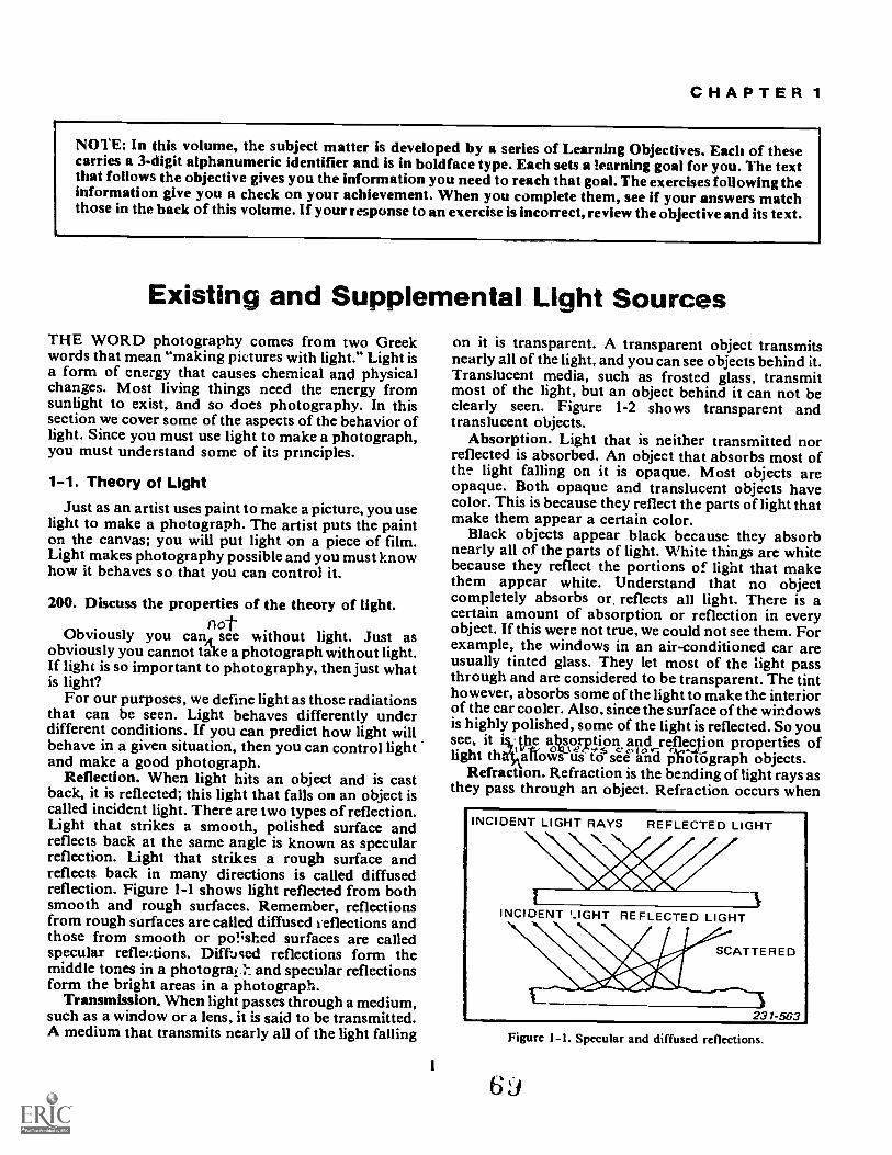
CHAPTER 1
NOTE: In this volume, the subject matter is developed by a series of Learning Objectives. Each of thesecarries a 3-digit alphanumeric identifier and is in boldface type. Each sets a !earning goal for you. The textthat follows the objective gives you the information you need to reach that goal. The exercises following theinformation give you a check on your achievement. When you complete them, see if your answers matchthose in the back of this volume. If your response to an exercise is incorrect, review the objective and its text.
Existing and Supplemental Light SourcesTHE WORD photography comes from two Greekwords that mean "making pictures with light." Light isa form of energy that causes chemical and physicalchanges. Most living things need the energy fromsunlight to exist, and so does photography. In thissection we cover some of the aspects of the behavior oflight. Since you must use light to make a photograph,you must understand some of its principles.
1-1. Theory of LightJust as an artist uses paint to make a picture, you use
light to make a photograph. The artist puts the painton the canvas; you will put light on a piece of film.Light makes photography possible and you must knowhow it behaves so that you can control it.
200. Discuss the properties of the theory of light.n ot
Obviously you canA see without light. Just asobviously you cannot tAe a photograph without light.If light is so important to photography, then just whatis light?
For our purposes, we define light as those radiationsthat can be seen. Light behaves differently underdifferent conditions. If you can predict how light willbehave in a given situation, then you can control lightand make a good photograph.
Reflection. When light hits an object and is castback, it is reflected; this light that falls on an object iscalled incident light. There are two types of reflection.Light that strikes a smooth, polished surface andreflects back at the same angle is known as specularreflection. Light that strikes a rough surface andreflects back in many directions is called diffusedreflection. Figure 1-1 shows light reflected from bothsmooth and rough surfaces. Remember, reflectionsfrom rough surfaces are called diffused teflections andthose from smooth or po!;shed surfaces are calledspecular reflections. Diffbwd reflections form themiddle tones in a photograf.:7. and specular reflectionsform the bright areas in a photograph.
Transmission. When light passes through a medium,such as a window or a lens, it is said to be transmitted.A medium that transmits nearly all of the light falling
1
on it is transparent. A transparent object transmitsnearly all of the light, and you can see objects behind it.Translucent media, such as frosted glass, transmitmost of the light, but an object behind it can not beclearly seen. Figure 1-2 shows transparent andtranslucent objects.
Absorption. Light that is neither transmitted norreflected is absorbed. An object that absorbs most oftly light falling on it is opaque. Most objects areopaque. Both opaque and translucent objects havecolor. This is because they reflect the parts of light thatmake them appear a certain color.
Black objects appear black because they absorbnearly all of the parts of light. White things are whitebecause they reflect the portions of light that makethem appear white. Understand that no objectcompletely absorbs or reflects all light. There is acertain amount of absorption or reflection in everyobject. If this were not true, we could not see them. Forexample, the windows in an air-conditioned car areusually tinted glass. They let most of the light passthrough and are considered to be transparent. The tinthowever, absorbs some of the light to make the interiorof the car cooler. Also, since the surface of the windowsis highly polished, some of the light is reflected. So yousee, it Iv the air .g3tion. and reflection properties oflight thaVarfav's rti sW AC-1 plizifograph objects.
Refraction. Refraction is the bending of light rays asthey pass through an object. Refraction occurs when
INCIDENT LIGHT RAYS REFLECTED LIGHT
INCIDENT UGHT REFLECTED LIGHT
SCATTERED
231-563
Figure 1-1. Specular and diffused reflections.
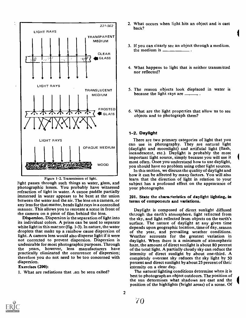
LIGHT RAYS
,.,
'
LIGHT RAYS
231-562
ANSPARENTMEDIUM
CLEARGLASS
TRANSLUCENT
11 FROSTED
GLASS
LIGHT RAYS
OPAQUE MEDIUM
WOOD
Figure 1-2. Transmission of light.light passes through such things as water, glass, andphotographic lenses. You probably have witnessedrefraction of light in water. A canoe paddle partiallyimmersed in water appears to be bent at the unionbetween the water and the air. The lens on a camera, orany lens for that matter, bends light rays in a controlledmanner. This allows you to recreate a scene in front ofthe camera on a piece of film behind the lens.
Dispersion. Dispersion is the separation of light intoits individual colors. A prism can be used to separatewhite light in this manner (fig. 1-3). In nature, the waterdroplets that make up a rainbow cause dispersion oflight. A camera lens would also disperse light if it werenot corrected to prevent dispersion. Dispersion isundesirable for most photographic purposes. Throughthe years, however, lens manufacturers havepractically eliminated the occurrence of dispersion;therefore you do not need to be too concerned withdispersion.Exercises (200):1. What are radiations that _an be seen called?
2
2. What occurs when light hits an object and is castback?
3. If you can clearly see an object through a medium,the medium is
4. What happens to light that is neither transmittednor reflected?
5. The reason objects look displaced in water isbecause the light rays are
6. What are the light properties that allow us to seeobjects and to photograph them?
1-2. DaylightThere are two primary categories of light that you
can use in photography. They are natural light(daylight and moonlight) and artificial light (flash,incandescent, etc.). Daylight is probably the mostimportant light source, simply because you will use itmost often. Once you understand how to use daylight,you should have no problem using other light sources.
In this section, we discuss the quality of daylight andhow it can be affected by many factors. You will alsolearn that the direction of light in relation to yoursubject has a profound effect on the appearance ofyour photographs
201. State the characteristics of daylight lighting, interms of components and variations.
Daylight is composed of direct sunlight diffusedthrough the earth's atmosphere, light refiteted fromthe sky, and light reflected from objects on the earth'ssurface. The nature of daylight at any given timedepends upon geographic location, time of day, seasonof the year, and prevailing weather conditions.Weather accounts for the greatest variation indaylight. When there is a minimum of atmospherichaze, the amount of direct sunlight is about 80 percentof the total light. A partially cloudy sky can reduce theintensity of direct sunlight by about one-third. Acompletely overcast sky reduces the sky light by 50percent and direct sunlight by about 25 percent of theik-intensity on a clear day.
The natural lighting conditions determine when it isbest to photograph an object outdoors. The position ofthe sun determines what shadows are cast and theposition of the highlights (bright areas) of a scene. Of
0
WHITE RAY OF LIGHT
RED
ORANGE
YELLOW
GREEN
BLUE
INDIGO
VIOLET
231-569
(EXAGGERATED)
Figure 1-3. Dispersion of light.
course, it is impossible to change the position of thesun, but you may be able to change the position of yoursubject. What if you are going to photograph a subjector scene on a bright sunny day where the shadows aretoo deep and the highlights are too bright? If you can'tmove your subject you still have an alternative. Waituntil you have an overcast day. On such days youwon't have to worrry about too much contrast. Figure1-4 gives a comparison of the same scenephotographed on a sunny day and on an overcast day.
Since the sun travels in an arc, moveable subjects canbe properly positioned.to provide the lighting that youdesire. In the early morning or late afternoon, longshadows are cast, but when it is close to noon, theshadows are much shorter.
Perhaps you have heard that the best way to take aphotograph is with the sun coming over your back.This "rule" stemmed from early days of photographywhen photographic films were not sensitive enough tobe used in shadows. It is no longer a rule but rather justanother method of using daylight.
Rontlighting. This is flatlighting, which can be aproblem because there are no visible shadows to createdepth in a photograph. Another problem of facingyour subject into the sun is that of eye squinting. Sincethe eyes are the most expressive part of a person's face,this is undesirable. See figure 1-5.
A better method of lighting your subject undersunny conditions is to have the sun strike your subjectat an angle or to the side. The shadows cast, as shownin figure 1-6, make the photograph much moreinteresting.
Backlighting. What about facing your camera intothe sun? This method is known as backlighting, and ifdone properly it makes for a successful photograph.You must be careful in aiming your camera and youshould use a lens shade. The biggest problem with thistype of lighting is that the subject's face is in a shadow.Special exposure considerations, the use of a reflector,or fill-in flash may be needed. A variation ofbacklighting is a situation known as open shade. Open
3
shade means you placc your subject in a shaded area,such as under a tree, using the open sky as yourbackground. Since the entire subject is in the shadedarea, the lighting is diffused and fairly even. Also, theopen sky behind the subject makes a pleasingbackground. Here again, exposure is the majorproblem when using open shade, but the results areoften very good. Figure 1-7 shows an open shadesituation.
Exercises (201):
1. Name three components of daylight.
2. What causes variatons in the quality of daylight?
3. What are flatlighting, backlighting, and openshade?
1-3. Incandescent Light SourcesBesides daylight, you can use almost any form of
light that gives your film adequate exposure, as long asthe film you are using is sensitive to that color of light.The most common source of light other than daylightis the radiant emissions caused by the burning ofmaterials. The light from these sources is calledartificial light. Actually, the light itself is real, just asany other illumination. The reason it is called artificialis because of the source that makes the light. The torch,the candle, the oil lamp, gas mantle lamps,incandescent electric light bulbs, and photographicflash bulbs trace man's progress in producingcontrollable artificial light sources. These light sourcesall share the fact that they are incandescent and they all
71
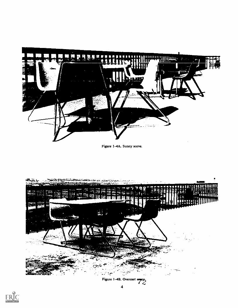
MIRO 11111111114 in pe r lig.malifinpseellilihilliiiiiill Nessr,4" ililljaigidl. ,g,
- 1----"--- a lin1 ,
i \s ._
.,I ---
1
. -...,
1
t
30'
11/
, ,
um: !e*- S re f- Ft; 4 F4
A .0.
1111111111111L
f
°141314 "1111 "1171.41
Varefari_
1
r '
INNer-O"'tenme 4.00,
4.61-
WIN-.111-
Pk;044r
.r.wNloquolzPoPmilmu
:
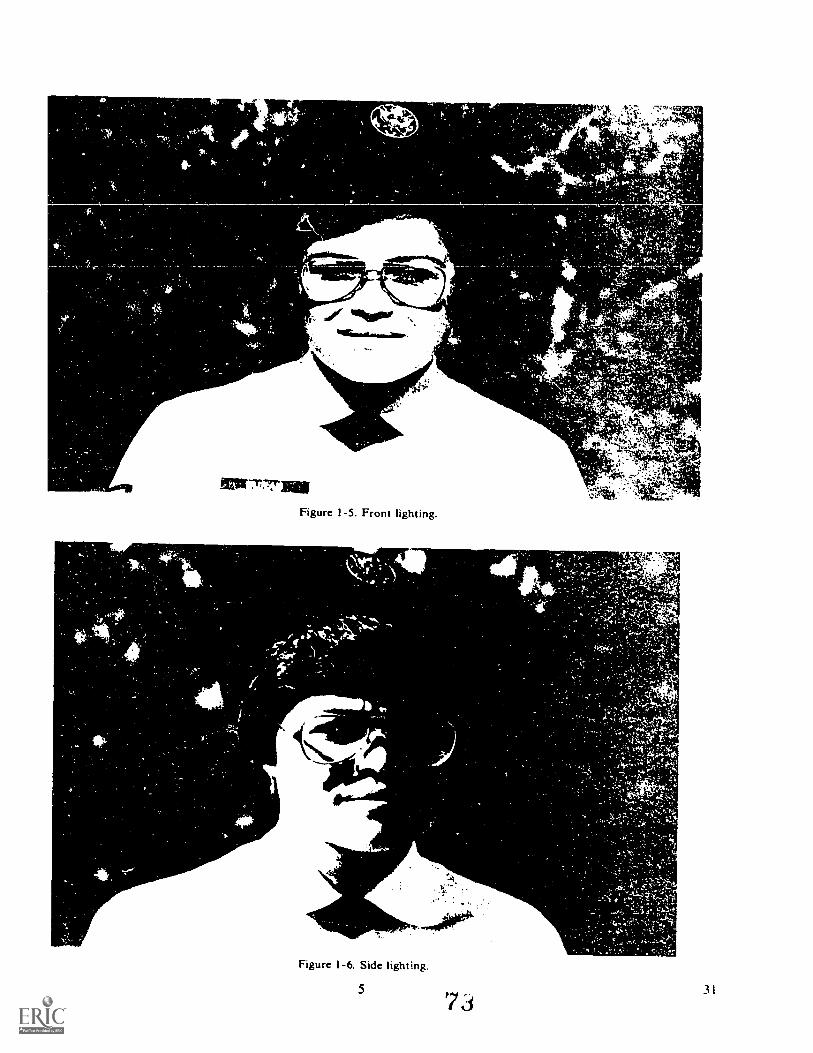
tilltrra,..matop
t,
-777.TINE
Figure 1-5. Front lighting.
'he "
Figure 1-6. Side lighting.
5
4
3 1
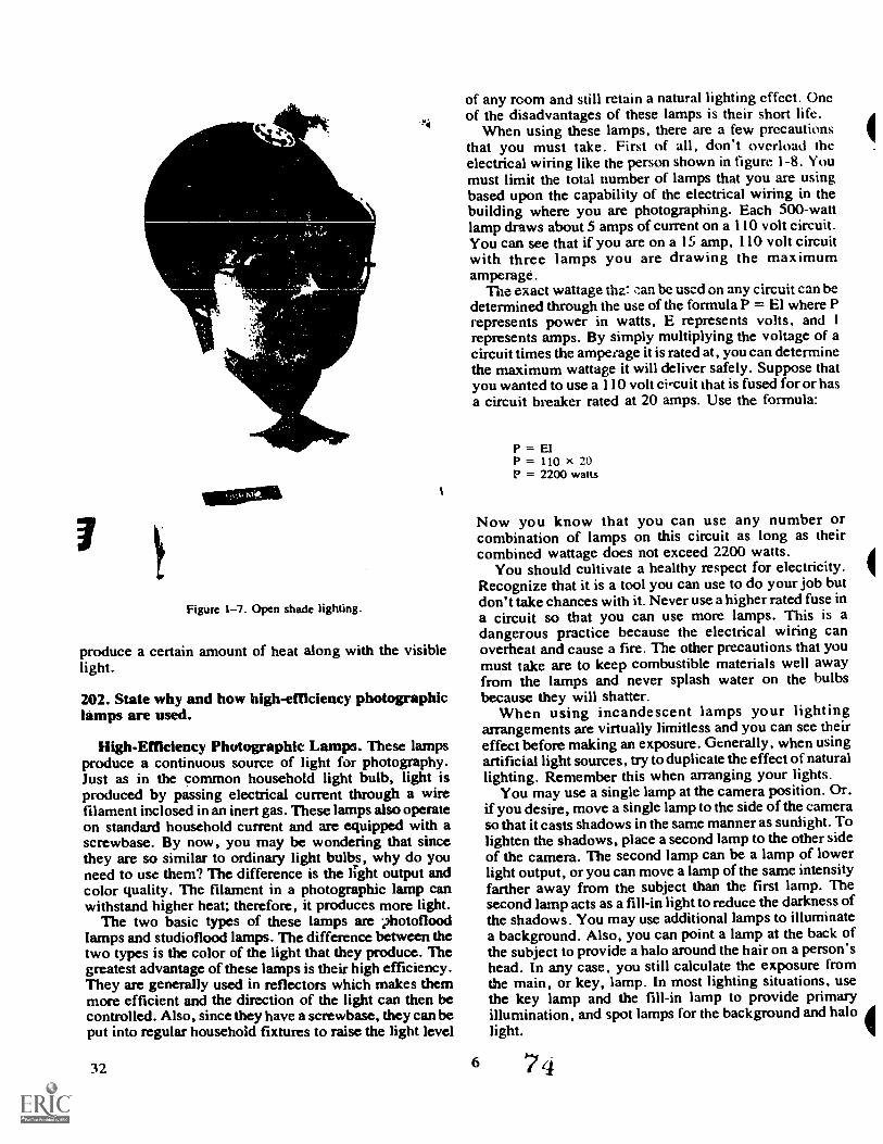
100:11
Figure 1-7. Open shade lighting.
produce a certain amountlight.
202. State why and howlamps are used.
of heat along with the visible
high-efficiency photographic
High-Efficiency Photographic Lamps. These lampsproduce a continuous source of light for photography.Just as in the common household light bulb, light isproduced by passing electrical current through a wirefilament inclosed in an inert gas. These lamps also operateon standard household current and are equipped with ascrewbase. By now, you may be wondering that sincethey are so similar to ordinary light bulbs, why do youneed to use them? The difference is the light output andcolor quality. The filament in a photographic lamp canwithstand higher heat; therefore, it produces more light.
The two basic types of these lamps are 2hotofloodlamps and studioflood lamps. The difference between thetwo types is the color of the light that they produce. Thegreatest advantage of these lamps is their high efficiency.They are generally used in reflectors which makes themmore efficient and the direction of the light can then becontrolled. Also, since they have a screwbase, they can beput into regular household fixtures to raise the light level
32
of any room and still retain a natural lighting effect. Oneof the disadvantages of these lamps is their short life.
When using these lamps, there are a few precautionsthat you must take. First of all, don't overload theelectrical wiring like the person shown in figure 1-8. Youmust limit the total number of lamps that you are usingbased upon the capability of the electrical wiring in thebuilding where you are photographing. Each 500-wattlamp draws about 5 amps of current on a 110 volt circuit.You can see that if you are on a 15 amp, 110 volt circuitwith three lamps you are drawing the maximumamperage.
The exact wattage the: can be used on any circuit can bedetermined through the use of the formula P = El where Prepresents power in watts, E represents volts, and 1represents amps. By simply multiplying the voltage of acircuit times the amperage it is rated at, you can determinethe maximum wattage it will deliver safely. Suppose thatyou wanted to use a 110 volt circuit that is fused for or hasa circuit breaker rated at 20 amps. Use the formula:
6
P = ElP = 110 x 20P = 2200 watts
Now you know that you can use any number orcombination of lamps on this circuit as long as theircombined wattage does not exceed 2200 watts.
You should cultivate a healthy respect for electricity.Recognize that it is a tool you can use to do your job butdon't take chances with it. Never use a higher rated fuse ina circuit so that you can use more lamps. This is adangerous practice because the electrical wiring canoverheat and cause a fire. The other precautions that youmust take are to keep combustible materials well awayfrom the lamps and never splash water on the bulbsbecause they will shatter.
When using incandescent lamps your lightingarrangements are virtually limitless and you can see theireffect before making an exposure. Generally, when usingartificial light sources, try to duplicate the effect of naturallighting. Remember this when arranging your lights.
You may use a single lamp at the camera position. Or.if you desire, move a single lamp to the side of the cameraso that it casts shadows in the same manner as sunlight. Tolighten the shadows, place a second lamp to the other sideof the camera. The second lamp can be a lamp of lowerlight output, or you can move a lamp of the same intensityfarther away from the subject than the first lamp. Thesecond lamp acts as a fill-in light to reduce the darkness ofthe shadows. You may use additional lamps to illuminatea background. Also, you can point a lamp at the back ofthe subject to provide a halo around the hair on a person'shead. In any case, you still calculate the exposure fromthe main, or key, lamp. In most lighting situations, usethe key lamp and the fill-in lamp to provide primaryillumination, and spot lamps for the background and halolight.
74

Exercises (202): 3. When you use incandescent light sources you shouldtry to duplicate the effects of _ lighting.I. Why are household bulbs not preferable for
photographic purposes as opposed to high-efficiencyphotographic lamps?
2. Are any precautionary steps necessary when usinghigh-efficiency photographic lamps? Explain briefly.
7 zi6 a 33
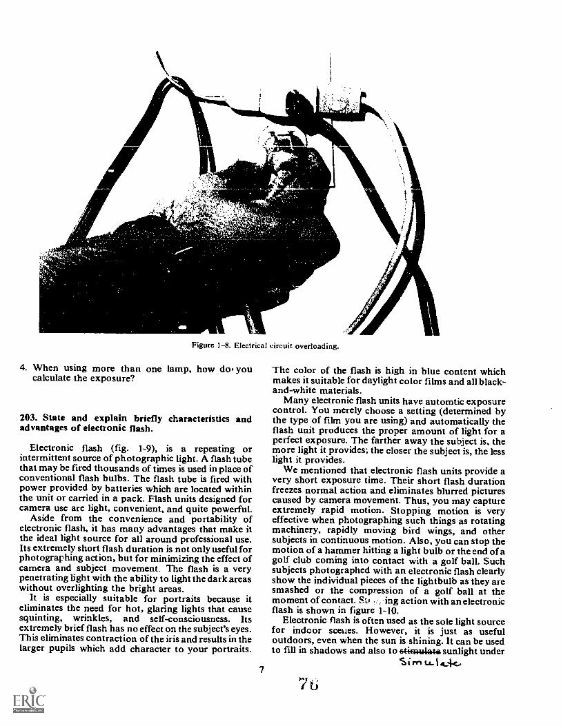
Figure 1-8. Electrical circuit overloading.
4. When using more than one lamp, how do youcalculate the exposure?
203. State and explain briefly characteristics andadvantages of electronic flash.
Electronic flash (fig. 1-9), is a repeating orintermittent source of photographic light. A flash tubethat may be fired thousands of times is used in place ofconventional flash bulbs. The flash tube is fired withpower provided by batteries which are located withinthe unit or carried in a pack. Flash units designed forcamera use are light, convenient, and quite powerful.
Aside from the convenience and portability ofelectronic flash, it has many advantages that make itthe ideal light source for all around professional use.Its extremely short flash duration is not only useful forphotographing action, but for minimizing the effect ofcamera and subject movement. The flash is a verypenetrating light with the ability to light the dark areaswithout overlighting the bright areas.
It is especially suitable for portraits because iteliminates the need for hot, glaring lights that causesquinting, wrinkles, and self-consciousness. Itsextremely brief flash has no effect on the subject's eyes.This eliminates contraction of the iris and results in thelarger pupils which add character to your portraits.
7
The color of the flash is high in blue content whichmakes it suitable for daylight color films and all black-and-white materials.
Many electronic flash units have automtic exposurecontrol. You merely choose a setting (determined bythe type of film you are using) and automatically theflash unit produces the proper amount of light for aperfect exposure. The farther away the subject is, themore light it provides; the closer the subject is, the lesslight it provides.
We mentioned that electronic flash units provide avery short exposure time. Their short flash durationfreezes normal action and eliminates blurred picturescaused by camera movement. Thus, you may captureextremely rapid motion. Stopping motion is veryeffective when photographing such things as rotatingmachinery, rapidly moving bird wings, and othersubjects in continuous motion. Also, you can stop themotion of a hammer hitting a light bulb or the end ofagolf club coming into contact with a golf ball. Suchsubjects photographed with an electronic flash clearlyshow the individual pieces of the lightbulb as they aresmashed or the compression of a golf ball at themoment of contact. St, , ing action with an electronicflash is shown in figure 1-10.
Electronic flash is often used as the sole light sourcefor indoor sceues. However, it is just as usefuloutdoors, even when the sun is shining. It can be usedto fill in shadows and also to otifnulato sunlight under
Sinn

Figure 1-9. Electronic flash units.
hazy skies. When used to make bright highlights andcast shadows, electronic flash approximates naturalsunlight conditions. Also, you may use a multiple flashsetup to provide specialized illumination of a scene.
A./.911iy.Exercises (203):
1. Name two distinct advantages of electronic flash.
2. Why is a short flash duration useful?
tia
iodine thereby creates a regeneration cycle thatincreases filament life and eliminates bulb blackening.
Quartz iodine (also called tungsten-halogen) lampsare compacte licient for their size, and maintaincons ar-F-IFEEIor quality. They are available in a varietyof sizes and color temperatures. They are commonlyused in copy, studio, and motion picture work wherethey prove superior to other types of incandescentlighting. 2), ecezr
iUsing quartz idilights s similar to using
photofloods or other types of continuoussupplemental lighting. Exposure can be determined byusing an exposure meter or by referring tomanufacturer's exposure guides.
heti One point to remember when working with quartz3. Is electronic flash effective as an outdoor light Taiu% lamps or any lighting system is safety. You mustsure that there is no overloading of circuits and that
the lamps are handled correctly. One of the key safetyivildse hazards with quartz jerlirre lamps is their intense heat.
They should be handled with special heat resistantcharacteristics and advantages of quarVz gloves when in use. Wearing gloves preventsfingerprints from being left on the quartz tube. These
source? Explain briefly.
204. Identify4odine lights.
All tungsten filaments are more efficient whenworking at high temperature. However, hightemperatures cause rapid evaporation of the filament;therefore, in a conventionally constructed light bulb,the lamp life is short. Research has shown that if ahalogen such as iodine vapoi is used in the lamp, itcombines with the evaporated tungsten, which is thenattracted to the hottest local surface, the filament. The
8
prints can etch into the glass because of the lamp sintense heat, and cause the lamp to shatter.
Exercise (204):
1. Which of the following lamp characteristics applyto the quartz itreiitte lamp? /7,2a. Cool burning. oc94e÷.1.
b. Synchronized to camera.
7 7
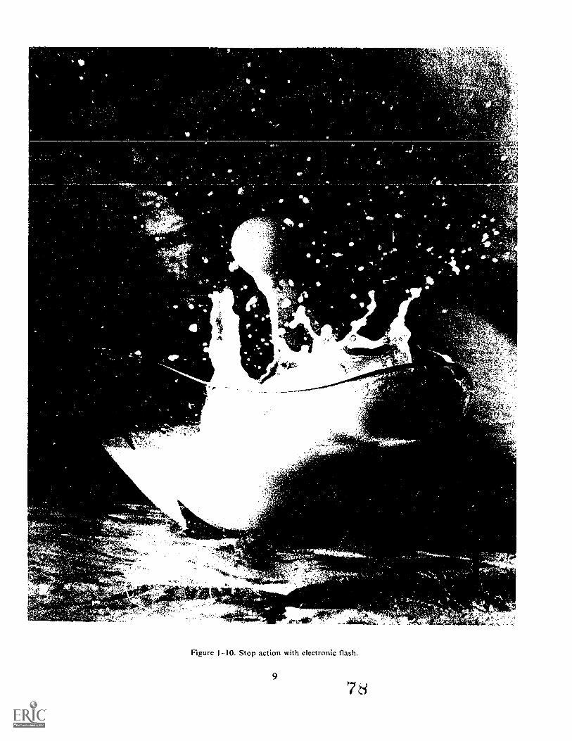
'r
'4**s.
Figure 1-10. Stop action with electronic flash.
9
4
r'
7s
;Vs
c. High intensity.d. Long life.e. Should be handled with gloves.f. Constant color temperature.g. Intermittent light source.h. Suitable for copy work.
205. Complete and explain a list of statementsconcerning the structure and function of fluorescentlighting.
The fluorescent light source uses the mercury-lampprinciple. Essentially, the fluorescent lamp is amercury-vapor lamp with vapor pressure and voltageadjusted so that the discharge produces little visiblelight, but creates a high emission of energy in theultraviolet region. The inside of the glass tube is coatedwith a phosphor which absorbs the radiation emittedby the mercury vapor and converts the short ultravioletinvisible wavelengths into longer visible wavelengths,producing visible light.
The color of the light from a fluorescent lamp iscontrolled by the phosophor coating. Variations of thiscoating are manufactured to produce variations inillumination. These lamps may be given names as whitefluorescent lights, daylight fluorescent lights, etc. Youwill be most concerned with fluorescent lighting whenyou go to offices to take pictures. If you want or need touse available light instead of your electronic flash orphotofloods you will have no problems if youremember a few important points.
10
First, fluorescent lights pulse because of thealternating current. This means that 60 times a secondthe current changes directions. During each pulse thelight quality and intensity change. Therefore, yourcamera exposure must catch the light when it is "on",rather than during one of these pulses. A shutter speedlonger than 1/60 second will insure you catch the lightr-operly.
The second point is that fluorescent lights areusually high in green light. This is no major problem inblack-and-white work but is of great concern when youare using color film.
We do not want to scare you away from usingfluorescent lights. Thc -.. are really no problem. Sincenearly all buildings use them, you should learn how touse fluorescent lights, not how to avoid them.
Exercises (205):
1. Complete the following statements aboutfluorescent lighting and explain briefly.a. The inside of a fluorescent tube is coated with
Why?
b. Use a shutter speed of when you usefluorescent lights. Why?
c. Fluorescent lights are high in light.When is this a factor?
Photographic ExposureIN CH A PTER 1 we discussed the theory of light andthe light sources that you will use in your work. In thischapter you will learn that in order to make aphotograph, you must be able to control light. Aproperly exposed negative is the starting point towardsproducing a good photograph. You cannot produce anacceptable negative without controlling light. In thischapter we discuss the theory of photographicexposure and how photographic exposure iscomputed.
2-1. Exposure Factors
Photographic exposure is the controlled applicationof light on film. Exposure sets the photographicprocess in motion to produce an end product. Youmust properly expose the film if you want to producean image with proper density and adequate detail.
206. State the basic formula for photographicexposure and the factors that control exposure.
The term "exposure" relates to the amount of image-forming light that is allowed to act upon the film. Thetwo factors that determine exposure are the intensity ofthe exposing light and the amount of time the light isallowed to strike the film. Therefore, exposure is lightintensity multiplied by time. Exposure can beexpressed in the formula: E = I X T, where intensity (I)multiplied by time (T) produces exposure (E).
You probably have experienced rainshowers ofvarying intensities. During a thundershower, a lot ofwater falls in a short period of time. However, somerainshowers are light, but if it rains lightly all day longthen the same amount of rain could possibly fall asduring a short heavy thundershower. So, it's theintensity of the rainfall and the length of time that itrains that determines the total amount of rainfall.Photographic exposure works i:. the same way. Intheory, a small amount of light striking the film for along period of time will produce the same totalexposure as a lot of light striking the film for only ashort period of time. Therefore, one unit of light actingon the film for 100 seconds produces the sameexposure as 100 units of light striking the film for onesecond.
Exercises (206):
1. What is the formula for photographic exposure?
11
CHAPTER 2
2. What are the factors that determine photographicexposure?
207. Given a series of exposure settings, determinetheir equivalent exposures.
Exposure Controls. You are familiar with the waterrushing from a faucet. As you open the faucet, morewater comes out. If you close the faucet and make thehole smaller, less water is allowed to come out. On acamera you have essentially a faucet, called thediaphragm. The diaphragm can be made larger orsmaller allowing more or less light to strike the film. Inthe exposure formula E = I X T, the diaphragmcontrols (I) or intensity.
Fl stops. In many cameras an iris diaphragm kfig. 2-1) is used to control light intensity.
This diaphragm consists of a series of overlappingleaves that form a circular opening between the lensand the film. The interlocking leaves are adjustable sothat the size of the circular opening that passes lightthrough to the film can be made larger or smaller.
An adjustable ring surrounding the lens barrel canbe rotated to increase or decrease the size of thediaphragm opening. The numbers marked on this ringare called f/ numbers or f/ stops. When the diaphragmring is moved to the smallest number (f/ 1.4 forexample) the diaphragm is wide open, which letsthrough the maximum amount of light. Moving to ahigher numbered f/ stop decreases the size of thediaphragm aperture, thereby reducing the amount oflight that can pass to the film.
Lens manufacturers have standardized f / stop scalesstarting with f/ 1 and progressing by the square root of2 through the various full f/stops. An importantadvantage of this system is that each higher numberedf /stop reduces the intensity of the light striking the filmby one-half. The term "full f/ stop" is applied to thefollowing f/ stops: f/ 1, f/ 1.4, f/ 2, f/ 2.8, f/ 4, f/ 5.6, f/ 8,f/ 11, f/ 16, f/ 22, and f/ 32. The term "lens speed" refersto the largest aperture (i.e., the smallest f/ number) ofthe lens.
The phrase "closing down a stop" means movingfrom one full f/stop to the next larger number, such asfrom f/ 11 to f/ 16. Doing this reduces the light intensityby one-half. Opening up one stop produces theopposite result. In this case, as you move from a largernumber to the next smaller number (f/ 16 to f/ 11), thelight intensity doubles.
3 0
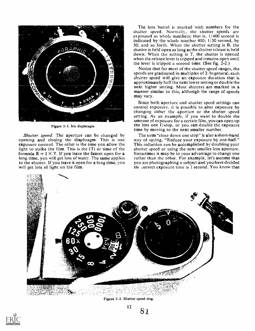
Figure 2-1. Iris diaphragm.
.$)
Shutter speed. The aperture can be changed byopening and closing the diaphragm. This is oneexposure control. The other is the time you allow thelight to strike the film. This is the (T) or time of theformula E = I X T. If you leave the faucet open for along time, you will get lots of water. The same appliesto the shutter. If you leave it open for a long time, youwill get lots of light on the film.
The lens barrel is marked with numbers for theshutter speed. Normally, the shutter speeds areexpressed as whole numbers; that is, 1/ 400 second isindicated by the whole number 400; 1/ 50 second, by50; and so forth. When the shutter setting is B, theshutter is held open as long as the shutter release is helddown. When the setting is T, the shutter is openedwhen the release lever is tripped and remains open untilthe lever is tripped a second time. (See fig. 2-2.)
Notice that for mcst of the shutter speed ranges, thespeeds are graduated in multiples of 2. In general, eachshutter speed will give an exposure &nation that isapproximately half the next lower setting or double thenext higher setting. Most shutters are marked in amanner similar to this, although the range of speedsmay vary.
Since both aperture and shutter speed settings cancontrol exposure, it is possible to alter exposure bychanging either the aperture or the shutter speedsetting. As an example, if you want to double theamount of exposure for a certain film, you can open upthe lens one f/ stop, or you can double the exposuretime by moving to the next smaller number.
The term "close down one stop" is also a short-handway of saying, "Reduce your exposure by one-half."This reduction can be accomplished by doubling yourshutter speed or using the next smaller lens aperture.Sometimes it may be to your advantage to change onerather than the other. For example, let's assume thatyou are photographing a subject and you have decidedth ,:orrect exposure time is I second. You know that
Figure 2-2. Shutter speed ring.
12
8 1
you can't hold the camera still for 1 second, so what doyou do? Use an equivalent exposure.
Equivalent Exposures. This term applies to anycombination of shutter speed and f/ stop that will give agood exposure. Remember that as the f/stop goes from11 to 16, you reduce the amount of light intensity byone-half. If you change your shutter speed from 1/ 100to 1/50 of a second you have doubled the amount oftime. Therefore, you should see that an exposure off/ 11 at 1/ 100 is the same as f/ 16 at I/ 50.
This is an easy method of setting equivalentexposures. As you move one setting one way (up),move the other one the other way (down). In otherwords, as your f/stop number gets larger, you mustmake your shutter speed number smaller.Consequently, as you change your f/ stop to a smallernumber you must change your shutter speed number toa larger number.
One more hint that may help: the higher the f/ stopnumber, the smaller the aperture hole.
Exercises (207):
1. Select the equivalent exposure settings for each ofthe following.a. 1/60 at f/ 8 is equal to: 1/25 at f/ 11.
1/30 at f/ 16.1/250 at f/ 4.
b. 1/250 at f/ 5.6 is equal to: 1/250 at f/ 2.8.1/500 at f/ 8.1/60 at f/ 11.
c. 1/30 at f/ 11 is equal to: 1/125 at f/8.1/60 at f/ 16.1/250 at f/4.
208. Briefly explain the law of reciprocity, theconditions under which there is likely to be a failure ofreciprocity, and the effect of reciprocity failure.
Reciprocity Law. Earlier, we defined exposure as theproduct of the intensity of the light reaching thesensitized material and the time of exposure: E = I X T.The amount of photographic chemical reaction, orsilver image density, is dependent upon the exposurereceived by the film or paper. This equation (E= I X T)is also known as the reciprocity law.
Applying 'the law of reciprocity, if no other factorsare involved, you can expect the same density on twosamples of sensitized materials having the same speed(assuming equal development), even though one sheetof the material is exposed to 500 units of light for 1second and the other to I unit of light for 500 seconds.The product of the light intensity and the time of thelight action is the same for each exposure.
Let's take another example. An exposure of 1/ 250second at f/ 8 is equal to an exposure of 1/60 at f/ 16. Ina practical sense, the reciprocity law holds true for thenormal range of exposure time, but the normal rangefor various sensitized materials differs considerably.Many films have a normal range of I second to 1/ 500second; others have a normal exposure range ofbetween 1/10 and 1/ 1,000 second. Failure of the
13
reciprocity law to apply in this normal range isinsignificant, and you can disregard it for mostpractical applications of photography. This is why youcan use published tables, exposure calculators, andxposure meters in most of your day-to-day
photography.Unfortunately, photographic emulsions do not
always correspond to constant results obtained whenlight intensity and exposure times are widely varied.The reciprocal relationship of intensity and time asoutlined in the exposure equation does not necessarilyhold true in some applications. Actually, film is lessresponsive when it is exposed under extremely high orlow light intensities as compared to exposure undermedium intensities. Both extremes are usually markedby very short or very long shutter speed settings.
It is interesting to note that at both extremes theeffect of reciprocity failure is an apparent loss of filmspeed. The loss of film speed results in anunderexposed negative. The extent of speed loss varieswith different emulsions under particular conditions,and no general rule can be given. Required exposurecompensation foi reciprocity failure must be found byexperimentation for each emulsion. The best insuranceagainst reciprocity failure is the use of the aperture,rather than extremes of shutter speeds, to controlexposure.
Exercises (208):
1 . Briefly explain the law of reciprocity.
2. Expla:,-, under what conditions there is likely to bereciprocity failure.
3. Explain the effect of reciprocity failure.
209. Define scene brightness range and briefly explainwhy the scene brightness range affects the informationthat is recorded on the film.
Scene Brightness Range. When viewing a typicalscene, your eyes respond to the color of light reflectedby each part of the subject. Your camera lens focusesthis light upon the film and forms an image in naturalcolor. However, black-and-white photographic filmscan only reproduce these colors in various shades ofgray. The density of these various shades depends onthe brightness of the reflectance of each subject colorand the color sensitivity of the film. The relativedifference between the brightest areas (highlights) andthe darkest areas (shadows) is termed the scenebrightness range (SBR).
Typical photographic scenes may have scenebrightness ranges from 1:2 to well over 1:500. That is to
82
say, by comparison, a shadow is 1/ 2 to 1/ 500 as brightas the highlight in the scene. Common film ci-nulsionsare capable of recording all of the extremely low scenebrightness ranges, but few can record very high ratiosof shadow to highlight brightness. The problem iscompounded by typical printing paper emulsions thatcan only record tone differences of 1:30 or less.
Most films are properly exposed when the brightestiaghlight creates the greatest practical image density.This pt,ictical maximum occurs when 128 times theminimum amount of light strikes the average black-and-white film. At this point, we can say that the rangeof the particular film is 1 to 128. Any object reflectingmore than 128 times the minimum amount of light willend up as a washed-out highlight.
When an original scene contains a greater brightnessrange than the film can capthre (for instance, a scenebrightness range of 1-to-600), photograph any slice ofthe scene that contains a 1-to-128 ratio of light units.You can photogiaph 2-to-256 light units or 4-to-512units; any ratio that reduces to 1 to 128. Remember,any areas that reflect less light than our low point resultin a clear negative, and areas above our high pointresult in a "blocked up" area of the negative.
Exercises (209):
1. Define scene brightness range.
2. Briefly explain why the scene brightness rangeaffects what information will be recorded on the
2-2. Exposure Calculators
Now that you have examined the theories of light,light sources, and exposure, you must learn how todctermine what exposure to use. In this next section wewill discuss the methods of determining what shutterspeed and aperture to use by employing different typesof exposure calculators.. The problem of calculating the exposure for anysubject involves the interrelation of two factors: thespeed of the film and the brightness of the subject. Weuse the American Standards Asse cation (ASA) filmspeed indexes for the exposure computation of speed.Two methods of judging brightness are visualestimation and the use of an exposure meter. Both havetheir individual merits; however, for consistent resultsunder various conditions, only a properly workingexposure meter should be used .
210. Given lighting and subject conditions, calculatethe correct exposure using the exposure guide in figure-3.
Visual Estimation. Visual estimation is based on7'..)ast experience with films of a given speed and
14
personal judgment of scene brightness. Because of thecharacteristics of the human cye, such brightnessjudgments are seldom very precise, althoughexperienced photographers can become quite skilled atmaking visual estimations under familiar conditions.
In the absence of an exposure meter, the followingsystem can be used to calculate a fairly accurate cameraexposure outdoors. The basic shutter setting is thereciprocal of the film speed. If the film's ASA rating is125, use 1/ 125 second as the shutter speed; if the speedis 250, use 1/ 250 second; and so forth. Your basicf / stop setting can be selected by using an ex;./osuretable. Many f lm packages contain tables such as theone shown in figure 2-3.
Using an Exposure Table or Guide. Completelyaccurate assessments of lighting conditions are seldompossible. However, most film emulsions have sufficientlatitude to cover any minor error you might make.Consider the following statements as aids in assessinglight conditions by visual estimation.
a. A bright sun and clear sky produces deep darkshadows of subjects in the scene. Use the Bright Suncolumn for erposures under these conditions.
b. If the sun's outline is visible behind a thin veil ofclouds, use the Hazy Sun column. In this case, the sun'sbrightness has been softened somewhat by a fine hazeover the sky or by thin clouds. As a result, the shadowsof objects are light and transparent.
c. If you can't see the sun and the sky is bright in thcdirection that the sun should be, use the Cloudy Brightcolumn. Many overcast days when the sun is hardlyvisible can be included in this classification. Snadowsof ground objects under these conditions are barelyvisible.
d. In the event the w. ole sky is covered with darkclouds, use the Open Shade column. This classificationalso applies when the subject is standing in the shadowof another object. By open shade, we mean it is possibleto see the clear sky overhead from the subject'sposition. In other words, the subject is standing in theshade of another object, and this shade is fairly evenover the entire area where the subject is located.
e. Use the Deep Shade column when supplementallighting of subjects in deep shade is not possible. Useextra care in making photographs in deep shade toinsure adequate shadow detail.
Next, turn your attention to the subject brightness.In a general snow scene or a beach scene with a lot ofreflection throughout the entire area, use the top rowlabeled brilliant. If the main subject, within the snow orbeach scene, is not reflecting very much light becausethe subject is dark colored, use the second row off/ stops labeled bright. Also, use the brightclassification when you estimate that the general sceneis reflecting more than 50 percent of the light striking it.Most of the subjects you will be photographing can beclassified as average. This means that they reflect 15 to50 percent of the light striking them. When it appearsto your eye that the subject is reflecting less than 15
83
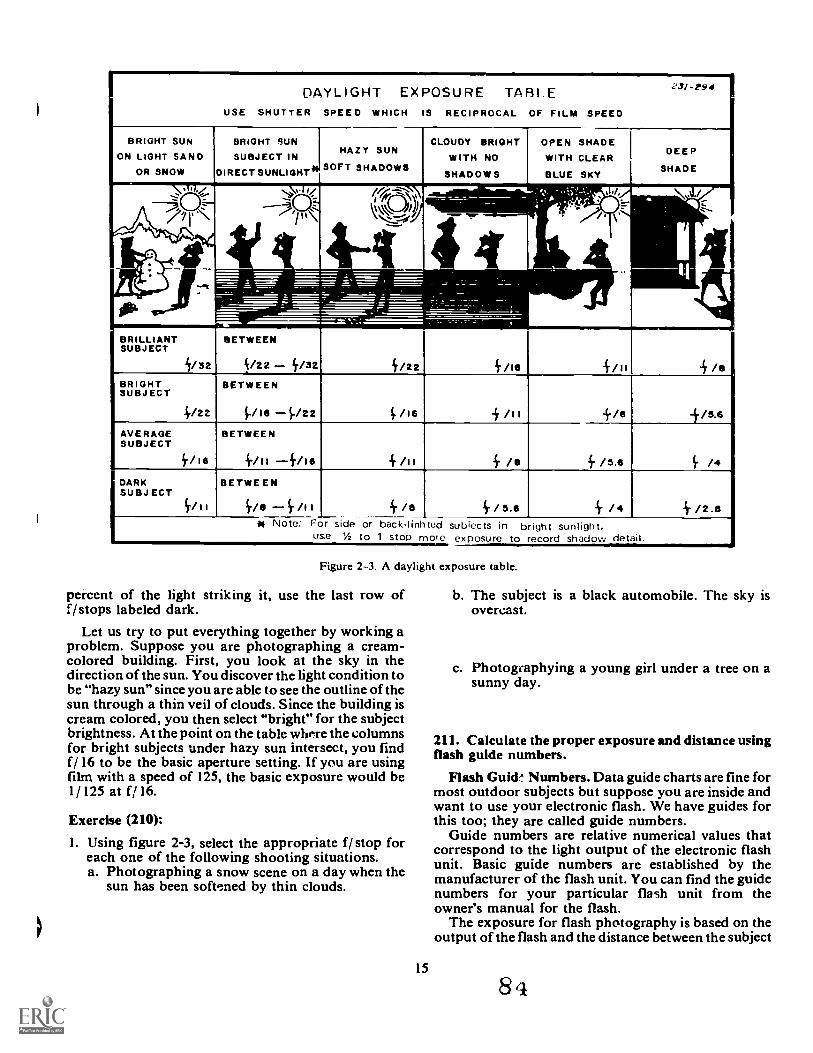
I
DAYLIGHTUSE SHUTTER
EXPOSURE TABLESPEED WHICH IS RECIPROCAL OF FILM SPEED
23/ -1094 I
BRIGHT SUN
ON LIGHT SANDOR SNOW
BRIGHT SUN IHAZY SUN
SUBJECT IN I
DIRECT SUNLIGHT SOFT SHADOWS
CLOUDY RIGHTWITH NO
SHADOWS
OPEN SHADEWITH CLEAR
BLUE SKY
DEEP
SHADE
61.d3i.
14-FrII)):..._--1:-./
1.
.:*: ,-a 14,./i .
. --
4 (,,'
..\
----=I= =IW MEW
_---. .-- 1.-. __-_.-.
: MW== s' ..- .
BRILLIANTSUBJECT
/32
BETWEEN
c/zz .... /32 i/sese ivis 4inBRIGHTSUBJECT
/22
BETWEEN
PI6 P22 PIS + /II /5.6
AVERAGESUBJECT
/16
BETWEEN
4/11 --ille /I 1 4s 4.is.e /4DARKSUBJ ECT
BETWEEN
i-/a i- /1 I Ir/e i./5.6 ir/ ir /2.6ii Note: For side or back-linhted subiects in b ight sunlight,
use 1/2 to 1 stop more exposure to record shadow detail.
Figure 2-3. A daylight exposure table.
percent of the light striking it, use the last row off/ stops labeled dark.
Let us try to put everything together by working aproblem. Suppose you are photographing a cream-colored building. First, you look at the sky in thedirection of the sun. You discover the light condition tobe "hazy sun" since you are able to see the outline of thesun through a thin veil of clouds. Since the building iscream colored, you then select "bright" for the subjectbrightness. At the point on the table where the columnsfor bright subjects under hazy sun intersect, you findf/ 16 to be the basic aperture setting. If you are usingfilm with a speed of 125, the basic exposure would be1/ 125 at f/ 16.
Exercise (210):
1. Using figure 2-3, select the appropriate f/ stop foreach one of the following shooting situations.a. Photographing a snow scene on a day when the
sun has been soft,:ned by thin clouds.
15
b. The subjectovercast.
is a black automobile. The sky is
c. Photogeaphying a young girl under a tree on asunny day.
211. Calculate the proper exposure and distance usingflash guide numbers.
Flash Guid, Numbers. Data guide charts are fine formost outdoor subjects but suppose you are inside andwant to use your electronic flash. We have guides forthis too; they are called guide numbers.
Guide numbers are relative numerical values thatcorrespond to the light output of the electronic flashunit. Basic guide numbers are established by themanufacturer of the flash unit. You can find the guidenumbers for your particular flash unit from theowner's manual for the flash.
The exposure for flash photography is based on theoutput of the flash and the distance between the subject
8
and thc flash. Guide na tubers provide a simplemathematical method of determining the properf /stop. For example, suppose you are using a flash unitwith a guide number of 160 and thc flash is 10 feet fromthe subject. To find the proper f/ stop, divide thedistance (10) into the guide nubmtr (160). The quotient(16) determines that f/ I 6 will give you the properexposure. NOTE: Shutter speed is not used in figuringyour electronic flash exposure because the duration ofthe flash is, in effect, the shutter speed.
Suppose you want to use a particular f / stop. Theguide number then helps you decide how far from thesubject to place your flash unit. For example, you wantto usc f/ 8 and your guide number is 64. In this casc,divide the f/ stop (8) into the guide number (64) andyou will find that to use f / 8 you need to put the flash 8feet from tilt. subject.
Synchronization. One more consideration for flashphotography is synchronization (sync). That is, theflash must light at the same time the shutter is open. Ifthe flash and shutter are not synchronized, you may getonly part of a picture, or even no picture.
Exercise (211):
I. Solve the following flash exposure problems.Guide Number Flash-to-Subject flistanee fistop
a. 160 10 ft.
b. 220 f/ 22
c. 80 f/ 8
d. 64 8 ft.
212. Exemplify the proper uses of exposure meters.Exposure meters are -ght-sensitive measuring
devices which convert light energy into electricalenergy on a pror.ortional basis. Available lightexposure meters employ two systems for making lightintensity readings. The incident method measures theintensity of light falling on the subject. The reflectedmethod measures the amount of light reflected by thesubject. For oe sake of discussion, we will examineeach method separately.
Incident Light Meters. The incident light metermeasures the light falling on the subject. This type ofmeter does not consider the tone value of the subject atall. Thus, it does not read the amount of light that isreflected by the subject. When using this type of meter,take into consideration the tonal value of the subject todetermine the scene brightness range.
16
Many of the modern exposure meters can giveincident or reflected light readings. Photoelectricexposure meters operate on a common principle and,as shown in figures 2-4 and 2-5, vary primarily in theirconfiguration for use. Light falls on a photoelectric cellthat creates an electrical current. The cell producespower in direct relation to the intensity of the light itreceives, and moves a needle that indicates lightintensity on a scale for exposure computation. Themore light there is, the greater the deflection of theneedle. In addition, the meter has a set of dials that,when set according to the proper film-speed index andthe scale reading of light intensity, gives the exposuredirectly, depending on the shutter speed or diaphragmopening desired.
Figure 2-4 shows the incident-light sphere thatgathers light for the photoelectric cell. The spherereceives the light from above, below, the front, and thesides. When held at the subject position and pointedtoward the camera (as in fig. 2-6), the incident-lightmeter measures the light falling on the subject.
When using an incident light meter, point the light-gathering receptor toward the camera. The meteraverages all of the light falling on the subject. This typeof metering is valuable when you have contrasting orback lighted subjects where the strong highlights mightcause erroneous reflected readings.
Reflected Light Meters. A reflected meter is used tomeasure light that is being reflected by the subjecttoward the camera. The meter is programmed to yielda reading that will reproduce a middle gray tone. If yt umeasure the light being reflected by a certain subject,
this reading for your exposure, and then processand print yo..Ar film correctly, the subject will appear amedium gray. All other parts of the scene that reflectedmore or less light than this subject will be lighter ordarker than middle gray. It is most important to realizea middle gray tone may not be the best representationof the subject, and you may have to modify yourexposure to achieve the right one.
Figure 2-7 illustrates the principle of reading withthe reflected light exposure meter. It measures theamount of light being reflected toward the camera bythe subject. Thus, this type of meter actually measuresthe picture-producing light. This is the most importantfeature of this type of lightA Use this meter to measurethe scene brightness range by taking separate readings "iof the highlight and shadow portions of the subject.
When taking a reflected light reading, it is importantto know exactly what part of the subject the meter isreading. Each type of meter has its own angle ofacceptance. Some meters read a very narrow area (suchmeters are often called "spot" meters) while others reada very wide angle. Sometimes, a meter will read toomuch of the shadow or highlight areas and cause aninaccurate exposure. Therefore, it is a good idea tomove in close to the subject so that you can make surethat the main subject is being measured.
There are basically three types of readings made witha reflected meter: (1) average, (2) brightness range, and(3) substitute. Let us see how each works.
85
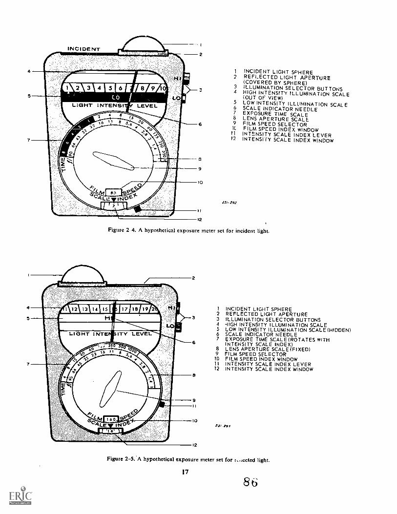
INCIDENT LIGHT SPHERE2 REFLECTED LIGHT APERTURE
(COVERED BY SPHERE)3 ILLUMINATION SELECTOR BUTTONS4 HIGH INTENSITY ILLUMINATION SCALE
(OUT OF VIEW)5 LOW INTENSITY ILLUMINATION SCALE6 SCALE INDICATOR NEEDLE7 EXPOSURE TIME SCALE8 LENS APERTURE SCALE9 FILM SPEED SELECTOR
lC FILM SPEED INDEX WINDOW11 INTENSITY SCALE INDEX LEVER12 INTENSITY SCALE INDEX WINDOW
23/- 292
Figure 2-4. A hypothetical exposure meter set for incident light.
1 INCIDENT LIGHT SPHERE2 REFLECTED LIGHT APERTURE3 ILLUMINATION SELECTOR BUTTONS4 -IIGH INTENSITY ILLUMINATION SCALE5 LOW INTENSITY ILLUMINATION SCALE (HIDDEN)6 SCALE INDICATOR NEEDLE7 EXPOSURE TIME SCALE (ROTATES WITH
INTENSITY SCALE INDEX)8 LENS APERTURE SCALE (FIXED)9 FILM SPEED SELECTOR
10 FILM SPEED INDEX WINDOW11 INTENSITY SCALE INDEX LEVER12 INTENSITY SCALE INDEX WINDOW
231,293
12
Figure 2-5.'A hypothetical exposure meter set for r..,Lected light.
17
8 6
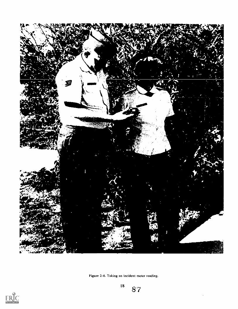
Figure 2-6. Taking an incident meter reading.
188'7
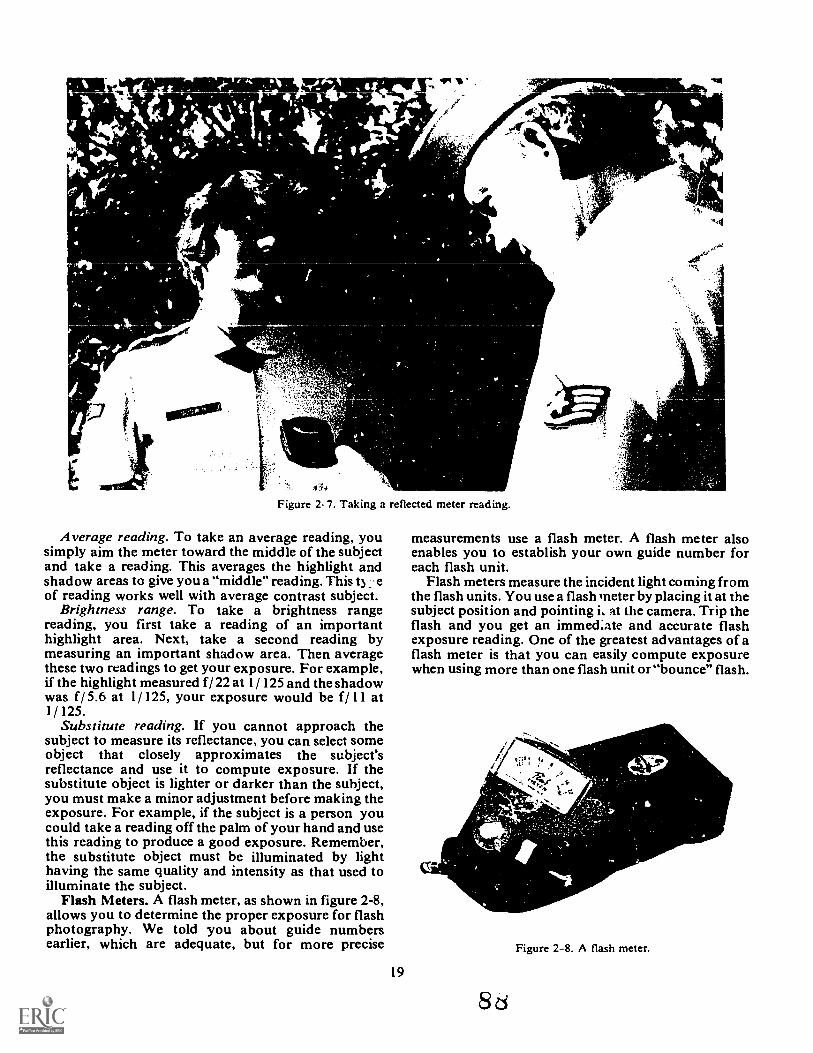
f.
Alsovo*-f
1111111111EL 'Figure 2-7. Taking a reflected meter reading.
Average reading. To take an average reading, yousimply aim the meter toward the middle of the subjectand take a reading. This averages the highlight andshadow areas to give you a "middle" reading. This t) eof reading works well with average contrast subject.
Brightness range. To take a brightness rangereading, you first take a reading of an importanthighlight area. Next, take a second reading bymeasuring an important shadow area. Then averagethese two readings to get your exposure. For example,if the highlight measured f/ 22 at 1/ 125 and the shadowwas f/ 5.6 at 1/ 125, your exposure would be f/ 11 at1/ 125.
Substitute reading. If you cannot approach thesubject to measure its reflectance, you can select someobject that closely approximates the subject'sreflectance and use it to compute exposure. If thesubstitute object is lighter or darker than the subject,you must make a minor adjustment before making theexposure. For example, if the subject is a person youcould take a reading off the palm of your hand and usethis reading to produce a good exposure. Remember,the substitute object must be illuminated by lighthaving the same quality and intensity as that used toilluminate the subject.
Flash Meters. A flash meter, as shown in figure 2-8,allows you to determine the proper exposure for flashphotography. We told you about guide numbersearlier, which are adequate, but for more precise
19
measurements use a flash meter. A flash meter alsoenables you to establish your own guide number foreach flash unit.
Flash meters measure the incident light coming fromthe flash units. You use a flash meter by placing it at thesubject position and pointing i, at the camera. Trip theflash and you get an immed:ate and accurate flashexposure reading. One of the greatest advantages of aflash meter is that you can easily compute exposurewhen using more than one flash unit or "bounce" flash.
d
"43,4446,_
e
%ct.r :V-11
Figure 2-8. A flash meter.
Exercise (212):
1. Answer the following statements true or false. andcorrect the false statements.a. Incident light meters measure the light falling on
a subject.
b. Incident light meters automatically allow for thetonal differences in the scene.
c. Point an incident light meter at the subject to getyour exposure setting.
d. A reflected light meter measures the lightbouncing off of the subject.
e. Many light meters can measure both reflectedand incident light.
f. You must use a separate flash meter for eachflash unit.
g. Use a flash meter at the subject position andpoint it at the camera.
213. State the proper use and care of an exposuremeter.
Care of Exposure Meters. Your exposure meter willlast for a long time if you don't drop it or otherwiseabuse it. To insure utmost accuracy, you should followthe appropriate operator's checklist and instructionalbooklet provided by the manufacturer. You shnuldalso consider the following points:
(1) Clean the glass over the photoelectric cell beforeuse. (NOTE: In dry weather, you may find that rubbinpthe glass with cloth can generate a static electricitycharge and cause the needle to give a false reading. Youcan remove the charge by breathing on the. glass.)
(2) Zero the meter. Cover the meter cell opening tocut off all the light. (With some meters you mustremove the batteries.) The needle should be at 0 or atan appropriate zero mark. Tilt the meter in variousdirectionsfrom side to side and up and down. Theneedle should not move more than the equivalent ofone-third of an f/ stop despite the position of the meter.If needed, adjust the needle until it zeroes.
(3) Check for sticky movement. Aim the meter cellat any light source until the needle is at about thehalfway mark on the scale. Cover the cell and uncoverit several times. The needle should go to 0 each time thf:cell is covered. Even with low light intensity, the meterpointer should move smoothly.
(4) Check for accuracy. Absolute accuracy tests arevery difficult, and it is impossible to check for themeter's accuracy every time you go on a cameramission. However, be sure the meter indicatesexposures that are logical on the basis of yourexperience or that match those indicated by anothermeter of known accuracy.
Always handle your meter correctly since the qualityof your photographs depends on correct exposuremetering. Consider the following operational DOs andDON'Ts.
DOProtect the meter from bumping against Jr,herobjects. Carry the meter in your pocket or camera casewhen it isn't in use. The meter case gives someprotection, but is not adequate for safety in extremeconditions.
DON'TSubject the photoelectric cell to lightintensities aboie those that are programmed by theselector switch. Extreme intensities may cause theindicator need e to bounce at the high end of the scaleand eventually cause damage to the unit.
DON'TSubject the exposure meter totemperatures above 125° F. (51.7° C). When you arenot using the meter, keep it in the carrying case andaway from heat.
DON'TPoint the photoelectric cell toward thesun. The cell may be "blinded" and give erroneousreadings for many hours.Exercises (213):
1. How do you zero an exposure meter?
2. Can subjecting a meter to very high intensities oflight cause permanent damage? Explain briefly.
3. What should be done with the meter when it is not inuse?
4. What will blind the photoele . cric cell?
214. Identify characteristics and describe the properuses of the gray zard.
Neutral Density Gray Card. There are times whenthe subject is so small that it is impossible for adjacentareas to be excluded from the exposure meter's field of
20
8 9
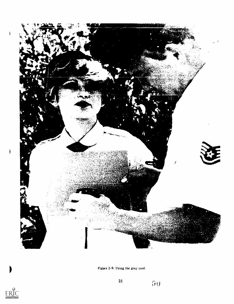
t .14kai
'
.;
"
,'
to. osrty.5....1
-`"1-:r.VAy kog
,' 2C
r -,....eNV",j -
Figure 2-9. Using the gray card.
21
view. Under these conditions, the meter may provideinaccurate exposure data. At other timet.., it isimpossible to approach the subject in order to take ameter reading. Also there are situations when thesubject is not available for you to make exposurereadings. For example, it is not possible to interruptsports activities in order to take a closeup reading.Under these and other conditions, a neutral test cardcan be substituted for the subject to assist you incalculating the correct exposure.
The neutral-test card is approximately 8 x 10 inches(20 x 25 cm) in size, gray on one side and white on theother. The gray side reflects 18 percent of the lightincident on it, while the white side reflects 90 percent ofthe light that strikes it.
There are three basic rules to be remembered whenusing a gray card:
(1) The illumination falling on the card must be ofthe same quality and intensity as that falling on thesubject.
(2) When you are using a gray card to estimateexposure, be sure to hold the meter close to the card.This way, light from surrounding areas will not strikethe meter's cell and produce erroneous readings.
(3) Make sure that the card is held perpendicular tothe ground. If it is held at an angle, either up or down, itwill produce inaccurate readings.
To use the gray card correctly, position it properly asshown in figure 2-9 and measure the light reflectedfrom it. Next, compare the reflectance of the card withthe reflectance of your subject. If the subject is lighter,select a smaller aperture; if the subject is darker, openthe aperture to admit more light.
When working under conditions of extremely lowillumination, it may not be possible to register areading on the gray side of the card. However, thewhite side of the card reflects five times as much light
22
and may provide sufficient reflectance to make anexposure reading. If the white side of the neutral testcard is used, you must remember that it shortens theexposure by five times over the reading provided by thegray side of the card. Typical subjects reflect less lightthan the white side of the neutral test card. If you usethe actual exposure data provided from this side of thecard, most of your negatives will be severelyunderexp osed .
As a general rule, open the aperture approximately21/2 f/stops over the white side reading. Another way ofcompensating for the white side of the test card is todivide the ASA by 5, then use that number on the lightmeter instead of the real speed index number. This willgive you the proper f/ stop.Exercise (214):
1. Identify each of the following statements as true orfalse, and correct the false statements.
a. The gray side of a neutral test card reflects 18percent of the light striking it.
b. You can take an incident reading off a gray card.
c. When using the white side of the neutral testcard, you need to increase your exposure 21/2f/stops.
d. When taking a reflective light reading off a graycard, the card should be held at a 450 angle to thesubject.
9
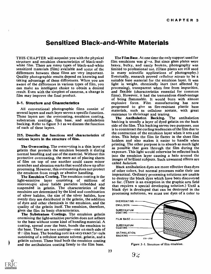
CHAPTER 3
Sensitized Black-and-White Materials
THIS CHAFFER will acquaint you with the physicalstructure and emulsion characteristics of black-and-white film. There are many types of black-and-whitesensitized materials (film) available and some of thedifferences between these films are very important.Quality photographic results depend on knowing andtaking advantage of these differences. When you areaware of the differences in various types of film, youcan make an intelligent choice to obtain a desiredresult. Even with the simplest of cameras, a change infilm may improve the final product.
3-1. Structure and CharacteristicsAll conventional photographic films consist of
several layers and each layer serves a specific function.These layers are: the overcoating, emulsion coating,substratum coatings, film base, and antihalationbacking. Refer to figure 3-1 as we discuss the functionof each of these layers.
215. Describe the functions and characteristics ofvarious layers in the structure of film.
The Overcoating. The overcnating is a thin layer ofgelatin that protects the emulsion beneath it duringnormal handling and use of the material. Without thisprotective overcoating, the mere act of placing sheetsof film on top of one another could cause minorscratches and abrasion marks that would show up afterprocessing. However, this overcoating does not protectthe emulsion from rough or abusive handling.
The Emulsion Coating. The emulsion coating is thelight-sensitive layer consisting of millions ofmicroscopic silver halide particles imbedded andsuspended in gelatin. The characteristics of theemulsion are determined by the kind and combinationof silver halides, the size of the silver halides, howevenly they are distributed in the gelatin, the additionof dyes and other chemicals in the emulsion, and thequality of the gelatin itself. The emulsion, therefore,gives the film its basic characteristics.
The Substratum Coatings. The emulsion gelatincontaining the light-sensitive particles does not adhereto the base without some kind of bonding material. Acoating, spread over the base, bonds the emulsion tothe base. There are two coatingsone on each side oftY film base. The bonding coat is a very exact forfnulaconsisting of a cellulose acetate solvent, gelatin, and agelatin solvent. These bind both the emulsion coatingand the antihalation coating firmly to the film base.
The Film Base. At one time the only support used forfilm emulsions was gbss. But since glass plates wereheavy, bulky, and easily broken, photography waslimited to professional use. (Glass platcs are still usedin many scientific applications of photography.)Eventually, research proved cellulose nitrate to be asuitable base material for the emulsion layer. It waslight in weight, chemically inert (not affected byprocessing), transparent when free from impurities,and flexible (characteristics essential for commonfilms). However, it had the tremendous disadvantageof being flammable. It would burn with almostexplosive force. Film manufacturing has nowprogressed to give us fire-resistant plastic basematerials, such as cellulose acetate, with greatresistance to shrinkage and tearing.
The Antihalation Backing. The antihalationbacking is usually a layer of dyed gelatin on the backside of the film. This backing serves two purposes, oneis to counteract the curling tendencies of the film due tothe contraction of the emulsion layer when it sets anddries. This helps the film lie flatter in the sheet filmholders and also makes it easier to handle whenprinting. The other purpose is to absorb as much lightas possible that goes through the film during theexposure. This light would otherwise be reflected backinto the emulsion layer causing a halo around theimages of brilliant subjects. Such unwanted effects arecalled halation.
Black antihalation dyes are more effective than dyesof other colors, but normal processes make their useimpractical. Ordinary processing solutions are unableto destroy the black dyes which have been discoveredso far. (There is an exception in the graphic arts fieldthat requires a special developing solution.) Until ablack dye is developed that can be destroyed in theprocessing solutions, we must use dyes of a color to
23
OVERCOATING
EMULSION
SUBSTRATUMCOATING
SUBSTRATUMCOATING
ANTIHALATIONBACKING
23/-256
Figure 3-1. Structure of film emulsion.
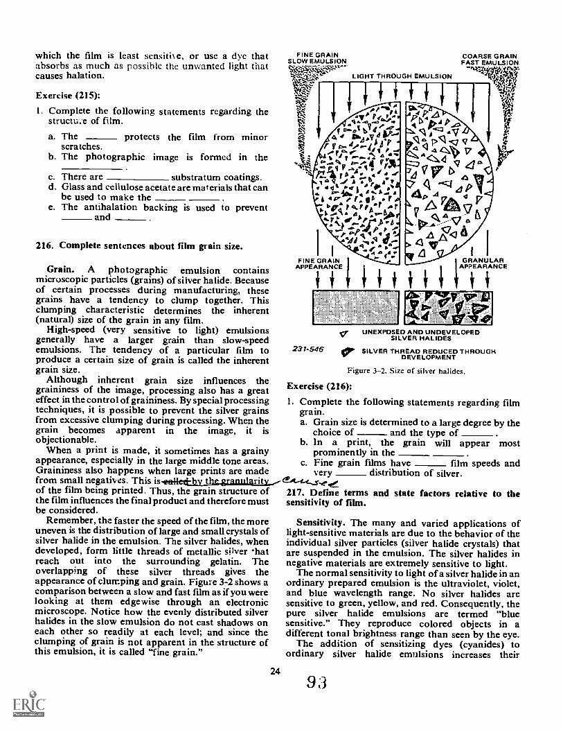
which the film is least sensiti e, or use a dye thatabsorbs as much as possible the unwanted light thatcauses halation.
Exercise (215):
1. Complete the following statements regarding thestructu.e of film.
a. The protects the film from minorscratches.
b. The photographic image is formed in the
c. There are substratum coatings.d. Glass and cellulose acetate are materials that can
be used to make thee. The antihalation backing is used to prevent
and
216. Complete sentences about film grain size.
Grain. A photographic emulsion containsmicroscopic particles (grains) of silver halide. Becauseof certain processes during manufacturing, thesegrains have a tendency to clump together. Thisclumping characteristic determines the inherent(natural) size of the grain in any film.
High-speed (very sensitive to light) emulsionsgenerally have a larger grain than slow-speedemulsions. The tendency of a particular film toproduce a certain size of grain is called the inherentgrain size.
Although inherent grain size influences thegraininess of the image, processing also has a greateffect in the control of graininess. By special processingtechniques, it is possible to prevent the silver grainsfrom excessive clumping during processing. When thegrain becomes apparent in the image, it isobjectionable.
When a print is made, it sometimes has a grainyappearance, especially in the large middle tone areas.Graininess also happens when large prints are madefrom small negatives. This isimiled-by therannlaritv---of the film being printed. Thus, the grain structure ofthe film influences the final product and therefore mustbe considered.
Remember, the faster the speed of the film, the moreuneven is the distribution of large and small crystals ofsilver halide in the emulsion. The silver halides, whendeveloped, form little threads of metallic silver 'hatreach out into the surrounding gelatin. Theoverlapping of these silver threads gives theappearance of clumping and grain. Figure 3-2 shows acomparison between a slow and fast film as if you werelooking at them edgewise through an electronicmicroscope. Notice how the evenly distributed silverhalides in the slow emulsion do not cast shadows oneach other so readily at each level; and since theclumping of grain is not apparent in the structure ofthis emulsion, it is called "fine grain."
FINE GRAINSLOW EMULSION
A
LIGHT THROUGH EMULSION
COARSE GRAINFAST EMULSION
dtscv..,F.
P P""e:: PA4/11 ..4 ft --e-
FINE GRAINAPPEARANCE
1A.P4DC;i6,4 p
pcVTz,
74 I Pi 46 VS"<lapl44p 41 0
V 46<ki:9C 1
<1ICV
W
4.
ItsI I
GRANULARAPPEARANCE
I i
231-546
UNEXPOSED AND UNDEVELOPEDSILVER HALIDES
VP SILVER THREAD REDUCED THROUGHDEVELOPMENT
Figure 3-2. Size of silver halides.
Exercise (216):
1. Complete the following statements regarding filmgrain.a. Grain size is determined to a large degree by the
choice of and the type ofb. In a print, the grain will appear most
prominently in thec. Fine grain films have film speeds and
very distribution of silver.
217. Define terms and state factors relative to thesensitivity of film.
Sensitivity. The many and varied applications oflight-sensitive materials are due to the behavior of theindividual silver particles (silver halide crystals) thatare suspended in the emulsion. The silver halides innegative materials are extremely sensitive to light.
The normal sensitivity to light of a silver halide in anordinary prepared emulsion is the ultraviolet, violet,and blue wavelength range. No silver halides aresensitive to green, yellow, and red. Consequently, thepure silver halide emulsions are termed "bluesensitive." They reproduce colored objects in adifferent tonal brightness range than seen by the eye.
The addition of sensitizing dyes (cyanides) toordinary silver halide emulsions increases their
2493
sensitivity to approximately the same spectral regionas that of the eye. Increasing the emulsion's lightsensitivity by dyeing (staining the silver halide crystals)is called optical sensitization. The increased sensitivitygained through the normal emulsion ripening processshould not be confused with optical sensitization, sincethe later is only the spectral sensitivity of the silverhalides. Optically sensitized emulsions are prepared byadding the sensitizing dyes in solution to the ripenedemulsion just prior to coating it onto the base.
When the pure silver halide emulsions are exposedto long wavelength radiations, (green, red, andinfrared), they do not react to any developable degree,and no change is brought about in the silver halidecrystals. The function of the sensitizing dyes is toabsorb the longer wavelengths of light and to transferthe effect to the silver halide. This produces the sameaction as direct absorption of light.
Color sensitivity is a very important characteristic ofnegative materials. Since it determines to a large extentthe tones in which colored objects are reproduced, it ismost important to know the color sensitivity of variouslight-sensitive materials. Figure 3-3 graphicallyillustrates the sensitivity of black-and-white negativematerial to different wavelengths of light.
The normal human eye response to light begins inthe violet region and extends through blue, green, andred regions. However, the sensitivity of the eye is notthe same for all wavelengths. Part A of figure 3-3 is agraphic curve that represents the relative response ofthe ey. shows that the eye has maximum sensitivity
I in the _ue-green and yellow-green portions of thecurve.
Compared to the eye, films may respond differentlyto light. Negative emulsions are classified into fourgeneral types according to the way they render colordifferences as brightness differences. These fourclassifications are: blue sensitive, orthochromatic(sensitive to blue and green), panchromatic (sensitiveto all the visible colors), and infrared emulsions(sensitive to blue, red, and part of the longerwavelengths beyond red). All silver halides aresensitive to ultraviolet radiation.
Exercises (217):
1. All silver halides are sensitive to what wavelengthsof light?
2. Define optical sensitization.
3. What type of film has color sensitivity similar tothat of the human eye?
25
218. Identify film latitude with particular fihncharacteristics.
Latitude. The ability of a film emulsion to record arange of subject brightnesses (range of reflected lightfrom the highlights through the shadows) is called filmlatitude. The range of brightnesses appearing on anegative or a print as shades of gray may be very great.An emulsion that is capable of rendering a long rangeof brightness values with satisfactory tone separation,has wide latitude. Conversely, if an emulsion canproduce only a short range of brightnesses, it hasnarrow latitude. These differences in film performancedetermine the film's inherent latitude.
Inherent latitude is often considered to be anexposure safety factor. The extent that the exposurecan be changed from normal, still giving an acceptableimage, is known as exposure latitude. Exposurelatitude is directly proportional to film latitude. If youhave film with wide latitude, you have wide exposurelatitude. In general, latitude in black-and-white films isrelated to film speed, with the faster speed films havingthe greater latitude. Exposure latitude permits you touse several possible exposures and still renderprintable negatives. As long as the range of tones in thescene maintain their same relationship, exposure'slatitude is correct.
Exercises (218):
1. Define film latitude.
2. Exposure latitude is directly related to what factor?
3. Latitude in black-and-white film is related to whatfilm characteristic?
219. Identify procedures for determining film speedand general characteristics of film speed.
Speed. Film speed is a term that is sometimesmisunderstood. Simply stated, however, it means thatsome films are affected by light much more quicklythan others. Film manufacturers have assigned a speednumber to each film. The higher this number, the fasterthe film. The biggest advantage of knowing the filmspeed number is that it allows you to make acomparison between the speed of one film and another.For example, if a film has a number double that ofanother, it means that it is twice as fast. Or stating theidea another way, it means that only half the amount oflight is required to affect the faster film to the samedegree.
Emulsion speed is of practical importance because ithas a direct bearing on the exposure required to
9 4
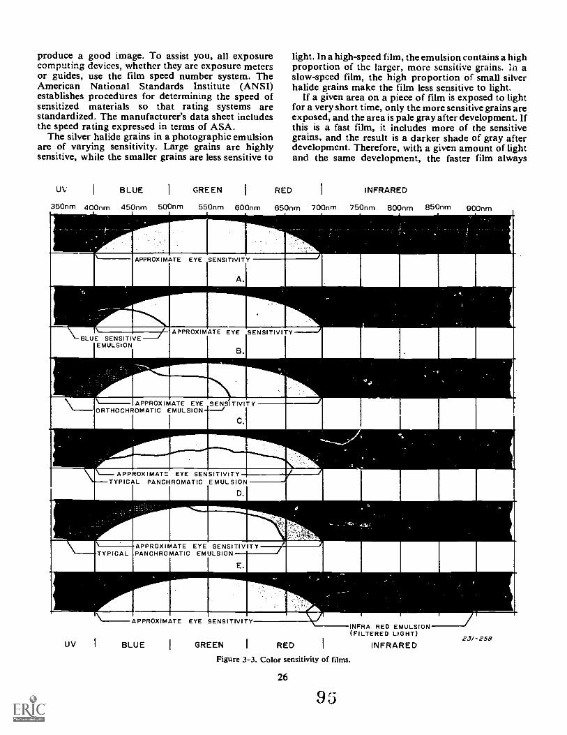
produce a good image. To assist you, all exposurecomputing devices, whether they are exposure metersor guides, use the film speed number system. TheAmerican National Standards Institute (ANSI)establishes procedures for determining the speed ofsensitized materials so that rating systems arestandardized. The manufacturer's data sheet includesthe speed rating expressed in terms of ASA.
The silver halide grains in a photographic emulsionare of varying sensitivity. Large grains are highlysensitive, while the smaller grains are less sensitive to
Uv BLUE GREEN
350nm 400nm 450nm 500nm 550nm 600nm
RED
light. In a high-speed film, the emulsion contains a highproportion of thc larger, more sensitive grains. In aslow-speed film, the high proportion of small silverhalide grains make the film less sensitive to light.
If a given area on a piece of film is exposed to lightfor a very short time, only the more sensitive grains areexposed, and the area is pale gray after development. Ifthis is a fast film, it includes more of the sensitivegrains, and the result is a darker shade of gray afterdevelopment. Therefore, with a given amount of lightand the same development, the faster film always
INFRARED
650nm 700nm 750nm 800nm 850nm 900nm
APPROX IMATE EYE SENSITIVIT YORTHOCHROMATIC EMULSION
ID.
APPROXIMATE EYE SENSITIPANCHROMATIC EMULSION
nallYE.
111111111
A PPROX WATS EYE SENSITIVITYTYPICAL PANCHROMATIC EMUL SION
A PPROX IMATE EYE SENSITIVITY
UV I BLUE GREEN I RED
INFRA RED EMULSION(FILTERED LIGHT)
INFRARED
Figure 3-3. Color sensitivity of films.
26
9 5
2.31-258

produces a darker shade of gray (greater density) thanthe slower film, since a greater percentage of silverhalides have been exposed and developed.
The practical application of a film speed number israther simple. Let us assume that you have been using aparticular film for a cunsiderable length of time.Through your experience in tz.sking photographs withthis film, you have found that when photographing abrilliant subject under daylight lighting conditions, thecorrect exposure is 1/ 125 of a second at f/ 16. This filmhas been rated at a speed of 125. Now suppose underthe same circumstances you want to use a film with aspeed of 250. What does this number mean to yov? Itsimply means that the new film is twice as sensitive tolight as the old one. To compensate for this increasedsensitivity, you could adjust either or both the camera'sshutter speed or diaphragm to make the necessarycorrection. The new exposure for this film could be1/125 at f/22, 1/250 at f/ 16, or 1/500 at f/ 11.
The film speed published by the manufacturer isusually computed for average conditions. You should,however, adjust the number according to yourparticular working methods and equipment, whichbecomes necessary when you consistently getoverexposed or underexposed negatives.
Choose your mission film with its speed in mind.Generally speaking, select the slowest speed film thatwill accomplish the mission objective. Slower speedfilm has finer grain and resolving power (sharpness).The amount of light available at the scene and theparticular shutter speed or f/ stop desired also dictatethe choice of film speed. For example, a portrait isnormally shot with a wide aperture to reduce depth offield (area of sharpness). Choosing a fast film for anoutdoor portrait on a sunny day would limit you to fastshutter speeds and small apertures. Conversely, underlow-light conditions where wide exposure latitude isnecessary, or on an airborne mission where fast shutterspeeds are desirable, a high-speed film is ideal.
Exercises (219):
I. What is the organization that establishesprocedures for determining film speed?
2. Complete the following statements in regard to filmspeed.
a. Knowing your film speed number is essential incalculating your photographic
b. A film with an ASA of 400 is twice as sensitive tolight as one having a rating of
27
c. Given the same exposure and development, thefaster speed film produces the greater
d. As a general rule, you should choose thespeed film that will accomplish the mission.
e. In sunny conditions, a speed film givesyou a wider choice of apertures and shutterspeeds.
220. Define film contrast and state selected factorsand characteristics related to it.
Contrast. Another factor in seiecting film is theinherent contrast of the emulsion. Film development,subject lighting, inherent or built-in film contrast areall contrast determining factors. Photographicemulsions, in varying degrees of inherent contrast,from vcry low to very high, are available. Your choiceof emulsion contrast is influenced by the nature of thesubject and whether it is desirable to decrease,maintain, or enhance contrast. It i.., therefore,important to choose your film with its inherentcontrast in mind.
Negative density is the result of exposure anddevelopment. The difference between the high and lowdensities of the various areas of the emulsion is calledcontrast. A bright area of the subject reflects a greatamount of light that produces a correspondingly heavydensity in the negative (highlight). A dark area reflectslittle light, resulting in a correspondingly thin density(shadow) in the negative.
The subject brightliesses in between these light anddark areas register as various densities called middletones. The difference in brightness, from the brightesthighlights to the deepest shadows, is the contrast.Normal contrast is represented by a full range ofdensities, including highlights, middle tones, andshadows. High contrast does not have a full range ofdensities, it consists primarily of highlights andshadows with little or no middle tones. Low contrasthas very little density differences.
Emulsions are manufactured with varying degrees ofinherent contrast for different applications. High-contrast (process) film is used to copy high-contrastblack-and-white subjects, such as line drawings.Medium and low-contrast films are t-...3ed to record alonger range of tones as in a portrait. Therefore, theselection of the film should be governed by the contrastof the subject and the rendition desired.
The inherent contrast is the maximum contrast thatan emulsion can produce with a minimum variation inexposure intensities. Usually, emi-Isin "hat have theslowest speed have the highest ...ontrast. Thereason is that the slow film 1, _miler and moreuniform silver halide crystals that respond more slowlyto light of loA intensities relative to light of high
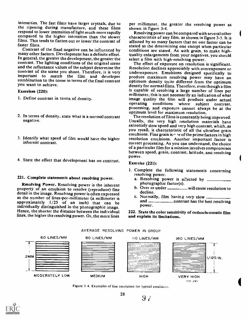
intensities. The fast films have larger crystals, due tothe ripening during manufacture, and these filmsrespond to lower intensities of light much more rapidlycompared to the higher intensities than the slowerfilms. This tends to flatten out or lower the contrast offaster films.
Contrast of the final negative can be influenced bymany other factors. Development has a definite effect.In general, the greater the development, thegreater thecontrast. The lighting conditions of the original sceneand the reflectance values of the subject determine thecontrast of the scene you shoot. Therefore, it is veryimportant to match the film and developercombination to the scene in terms of the final contrastyou want to achieve.
Exercises (220):
1. Define contrast in terms of density.
2. In terms of density, state what is a normal contrastnegative.
3. Identify what speed of film would have the higherinherent contrast.
4. State the effect that development has on contrast.
221. Complete statements about resolving power.
Resolving Power. Resolving power is the inherentproperty of an emulsion to resolve (reproduce) finedetail in the image. Resolving power is often expressedas the number of lines-per-millimeter (a millimeter isapproximately 1/ 25 of an inch) that can beindividually distinguished in the photographic image.Hence, the shorter the distance between the individuallines, the higher the resolving power. Or, the more lines
60 LINES/MM
.2MM
per millimeter, the greater the resolving power asshown in figure 3-4.
Resolving power can be compared with several othercharacteristics of any film, as shown in figure 3-5. It isaffected by so many factors that no one factor can bestated as the determining one except when particularconditions are stated. As with grain, to make high-quality enlargements from your negatives, you shouldselect a film with high-resolving power.
The effect of exposure on resolution is significant.Resolution declines appreciably with overexposure orunderexposure. Emulsions designed specifically toproduce maximum resolving power may have anoptimum density quite different from the optimumdensity for normal films. Therefore, even though a filmis capable of resolving a large number of lines permillimeter, this is not necessarily an indication of whatimage quality the film will produce under actualoperating conditions where subject contrast,processing, and exposure cannot always be at theoptimum level for maximum resolution.
The resolution of films is constantly being improved.Usually, the very high resolution materials haveextremely slow speed and very high contrast, which,asyou recall, is characteristic of all the ultrafine grainemulsions. Fine grain is f- le of the prime factors in highresolution emulsions. Another important factor iscorrect processing. As you can understand, the choiceof a particular film for a mission involves compromisesbetween speed, grain, contrast, latitude, ana resolvingpower.
Exercise (221):
1. Complete the following statements concerningresolving power.a. Resolving power is affected by
photographic factor(s).b. Over or under will cause resolution to
decline.c. Normally, film havir.g very slow
and contrast has the best resolvingpower.
222. State the color sensitivity of oi thochromatic filmand explain its limitations.
AVERAGE RESOLVING POWER IN GROUP
80 L1NES/MM h0 LINES/MM
MODERATELY LOW MEDIUM HIGH
Figure 3-4. Examples of line resolution for typical emulsions.
289
180 LINES/MM
VERY HIGH23/ 26/
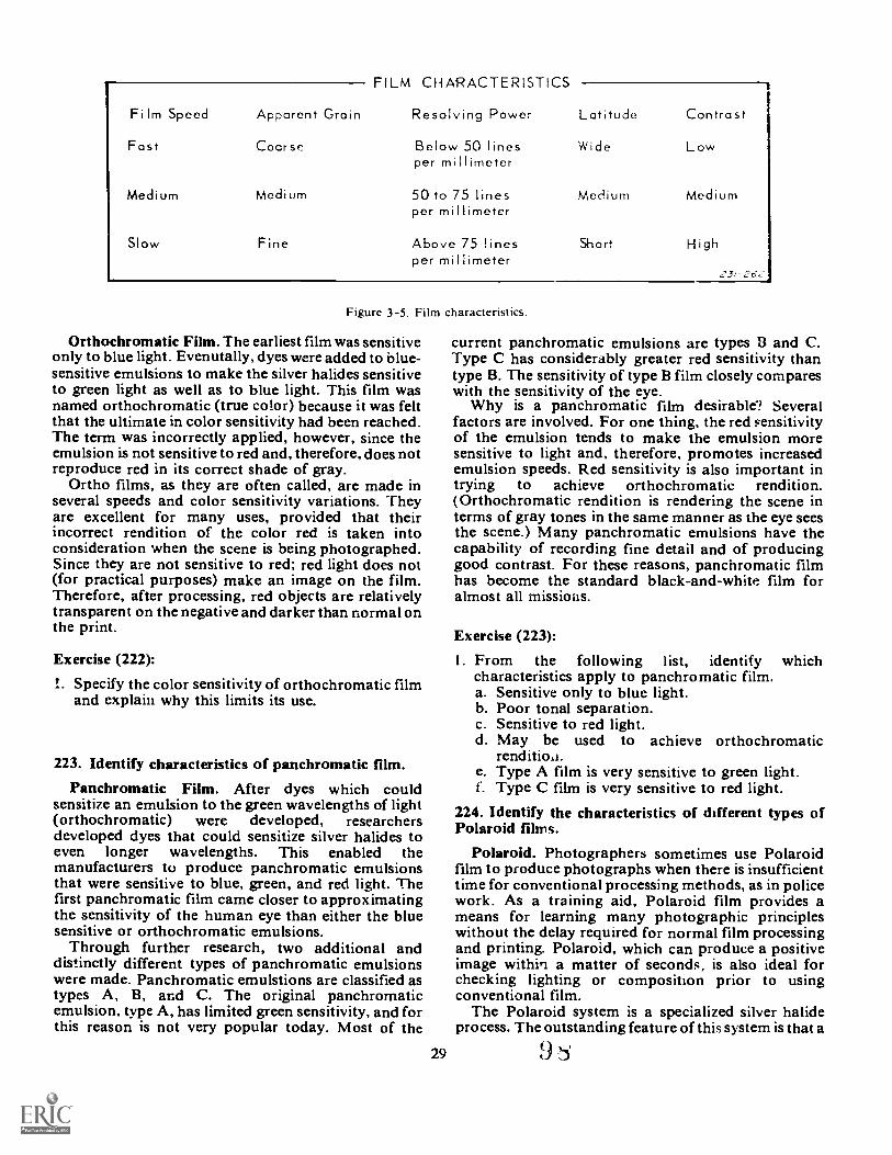
Film Speed
Fast
Medium
Slow
Apparent Grain
Coarse
Medium
Fine
FILM CHARACTERISTICS
Resolving Power
Below 50 linesper mi Hirneter
50 to 75 linesper millimeter
Above 75 linesper millimeter
Latitude Contrast
Wide
Medium
Short
Low
Medium
High
2Jf 262
Figure 3-5. Film characteristics.
Orthochromatic Film. The earliest film was sensitiveonly to blue light. Evenutally, dyes were added to blue-sensitive emulsions to make the silver halides sensitiveto green light as well as to blue light. This film wasnamed orthochromatic (true color) because it was feltthat the ultimate in color sensitivity had been reached.The term was incorrectly applied, however, since theemulsion is not sensitive to red and, therefore, does notreproduce red in its correct shade of gray.
Ortho films, as they are often called, are made inseveral speeds and color sensitivity variations. Theyare excellent for many uses, provided that theirincorrect rendition of the color red is taken intoconsideration when the scene is being photographed.Since they are not sensitive to red; red light does not(for practical purposes) make an image on the film.Therefore, after processing, red objects are relativelytransparent on the negative and darker than normal onthe print.
Exercise (222):
I. Specify the color sensitivity of orthochromatic filmand explain why this limits its use.
223. Identify characteristics of panchromatic film.Panchromatic Film. After dyes which could
sensitize an emulsion to the green wavelengths of light(orthochromatic) were developed, researchersdeveloped dyes that could sensitize silver halides toeven longer wavelengths. This enabled themanufacturers to produce panchromatic emulsionsthat were sensitive to blue, green, and red light. Thefirst panchromatic film came closer to approximatingthe sensitivity of the human eye than either the bluesensitive or orthochromatic emulsions.
Through further research, two additional anddistinctly different types of panchromatic emulsionswere made. Panchromatic emulstions are classified astypes A, 13, and C. The original panchrornaticemulsion, type A, has limited green sensitivity, and forthis reason is not very popular today. Most of the
current panchromatic emulsions are types B and C.Type C has considerably greater red sensitivity thantype B. The sensitivity of type B film closely compareswith the sensitivity of the eye.
Why is a panchromatic film desirable? Severalfactors are involved. For one thing, the red sensitivityof the emulsion tends to make the emulsion moresensitive to light and, therefore, promotes increasedemulsion speeds. Red sensitivity is also important intrying to achieve orthochromatic rendition.(Orthochromatic rendition is rendering the scene interms of gray tones in the same manner as the eye seesthe scene.) Many panchromatic emulsions have thecapability of recording fine detail and of producinggood contrast. For these reasons, panchromatic filmhas become the standard black-and-white film foralmost all missions.
Exercise (223):
1. From the following 1 ist, identify whichcharacteristics apply to panchromatic film.a. Sensitive only to blue light.b. Poor tonal separation.c. Sensitive to red light.d. May be used to achieve orthochromatic
rendition.e. Type A film is very sensitive to green light.f. Type C film is very sensitive to red light.
224. Identify the characteristics of different types ofPolaroid films.
Polaroid. Photographers sometimes use Polaroidfilm to produce photographs when there is insufficienttime for conventional processing methods, as in policework. As a training aid, Polaroid film provides ameans for learning many photographic principleswithout the delay required for normal film processingand printing. Polaroid, which can produce a positiveimage within a matter of seconds, is also ideal forchecking lighting or composition prior to usingconventional film.
The Polaroid system is a specialized silver halideprocess. The outstanding feature of this system is that a
29 9
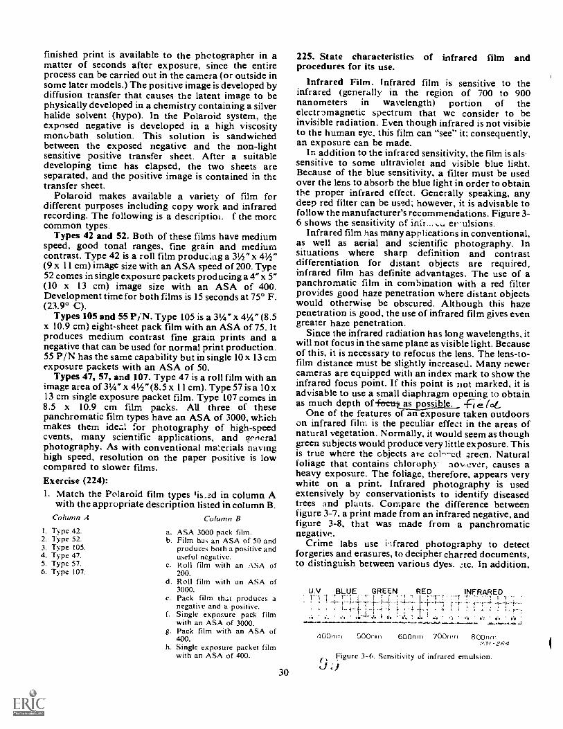
finished print is available to the photographer in amatter of seconds after exposure, since the entireprocess can be carried out in the camera (or outside insome later models.) The positive image is developed bydiffusion transfer that causes the latent image to bephysically developed in a chemistry containing a silverhalide solvent (hypo). In the Polaroid system, theexposed negative is developed in a high viscositymonubath solution. This solution is sandwichedbetween the exposed negative and the non-lightsensitive positive transfer sheet. After a suitabledeveloping time has elapsed, the two sheets areseparated, and the positive image is contained in thetransfer sheet.
Polaroid makes available a variety of film fordifferent purposes including copy work and infraredrecording. The following is a descriptior. f the morecommon types.
Types 42 and 52. Both of these films have mediumspeed, good tonal ranges, fine grain and mediumcontrast. Type 42 is a roll film producing a 3I/2" x 41/2"(9 x 11 cm) image size with an ASA speed of 200. Type52 comes in single exposure packets producing a 4" x 5"(10 x 13 cm) image size with an ASA of 400.Development time for both films is 15 seconds at 75° F.(23.9° C).
Types 105 and 55 P,N. Type 105 is a 31/4" x 41/4" (8.5x 10.9 cm) eight-sheet pack film with an ASA of 75. Itproduces medium contrast fine grain prints and anegative that can be used for normal print production.55 P/N has the same capability but in single 10x 13 cmexposure packets with an ASA of 50.
Types 47, 57, and 107. Type 47 is a roll film with animage area of 31/4" x 41/2" (8.5 x 11 cm). Type 57 is a 10 x13 cm single exposure packet film. Type 107 comes in8.5 x 10.9 cm film packs. All three of thesepanchromatic film types have an ASA of 3000, whichmakes them ide :or photography of high-speedevents, many scientific applications, and generalphotography. As with conventional ma::erials nay inghigh speed, resolution on the paper positive is lowcompared to slower films.Exercise (224):1. Match the Polaroid film types lis_zd in column A
with the appropriate description listed in column B.Column A
I. Type 42.2. Type 52.3. Type 105.4. Type 47.5. Type 57.6. Type 107.
Co lunzn B
a. ASA 3000 pack film.b. Film has an ASA of 50 and
produces both a positive anduseful negative.
c. Roll film with an ASA of200.
d. Roll film with an ASA of3000.
e. Pack film that produces anegative and a positive.
f. Single exposure pack filmwith an ASA of 3000.
g. Pack film with an ASA of400.
h. Single exposure packet filmwith an ASA of 400.
30
225. State characteristics of infrared film andprocedures for its use.
Infrared Film. Infrared film is sensitive to theinfrared (generally in the region of 700 to 900nanometers in wavelength) portion of theelectromagnetic spectrum that wc consider to beinvisible radiation. Even though infrared is not visibleto the human eye, this film can "see" it; consequently,an exposure can be made.
In addition to the infrared sensitivity, the film is alssensitive to some ultraviolet and visible blue light.Because of the blue sensitivity, a filter must be usedover the lens to absorb the blue light in order to obtainthe proper infrared effect. Generally speaking, anydeep red filter can be used; however, it is advisable tofollow the manufacturer's recommendations. Figure 3-6 shows the sensitivity of infi er ulsions.
Infrared film has many applications in conventional,as well as aerial and scientific photography. Insituations where sharp definition and contrastdifferentiation for distant objects are required,infrared film has definite advantages. The use of apanchromatic film in combination with a red filterprovides good haze penetration where distant objectswould otherwise be obscured. Although this hazepenetration is good, the use of infrared film gives evengreater haze penetration.
Since the infrared radiation has long wavelengths, itwill not focus in the same plane as visible light. Becauseof this, it is necessary to refocus the lens. The lens-to-film distance must be slightly increased. Many newercameras are equipped with an index mark to show theinfrared focus point. If this point is not marked, it isadvisable to use a small diaphragm opening to obtainas much depth of fecatas possible. (c,t,
One of the features of an exposure taken outdoorson infrared film is the peculiar effect in the areas ofnatural vegetation. Normally, it would seem as thoughgreen subjects would produce very little exposure. Thisis true where the objects arc colr-ed zreen. Naturalfoliage that contains chlorophy nov ever, causes aheavy exposure. The foliage, therefore, appears verywhite on a print. Infrared photography is usedextensively by conservationists to identify diseasedtrees and plants. Compare the difference betweenfigure 3-7, a print made from an infrared negative, andfigure 3-8, that was made from a panchromaticnegative.
Crime labs use infrared photography to detectforgeries and erasures, to decipher charred documents,to distinguish between various dyes, ztc. In addition,
U.V. BLUE GREEN RED INFRARED.T T r
: ' .' i I r 1.-1, t-
400n m 500n ru 600n In 700n rn 80C:turnP3/-264
Figure 3-6. Sensitivity of infrared emulsion.t-1 ;I
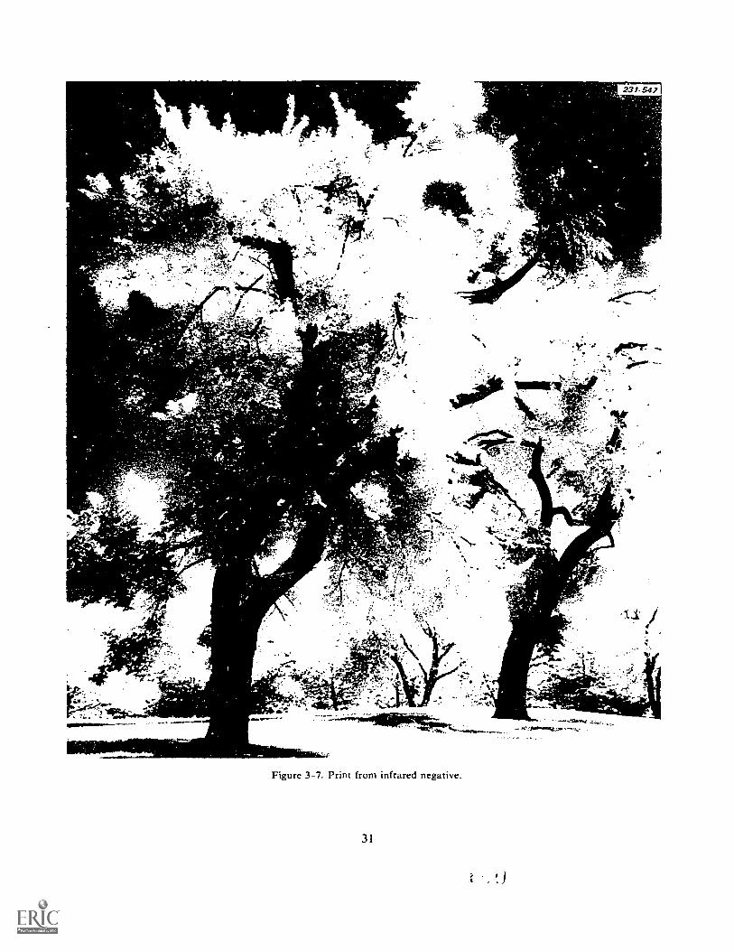
S.
-
- "Ai
AP
:41.1Ibwr
0,7
d". ' . :40.713.1t*At-:4,4:..,., . i
,.,: ,t _, .E.
....... 4--t;' ,r_..-..; .
-
, .'"In!, 4; . " _ , .
N,.... ..
.1 .
j.
/Let
v
Je.
-nv
- ... ,:i ,\̀ re /....0.
4....' 'V. Z404 it,- . ; A 4 : -.
-11-1: I .ier
ii.
a "to
Figure 3-7. Print from infrared negative.
31
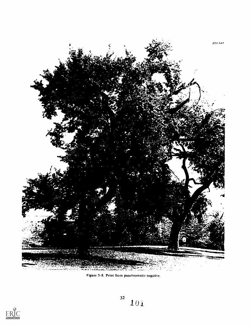
le '.s.
..:-
..-.,-
''--
, tr.
111:081,
..
..,
.'
- '....r..'0.1
I....
,.
.1 "'../.
ii'-1'
s .'
T'.
*'
AR
7' %.I .)
:,..} ...
.10. "t 9,/,111,' f,) '
t., '
./...s 'fir
'.Le' .'
''. ) ''C
.
.t....
i'i..)
'''i
k;
II! ic",?,7'..
17:-.'.:/
,,s
,*ss.
,,,,,.4,.; 110 vi
''
- I 4.'
.:.(
.4...
,...... -,
$.
...,.-
.4,...%-fy
,.
.7,.,
.; 4,A
..,j r
Y.
i.*
1 '` .
, 4i , .
V.
I.
4_1.' 0,4*
A.
s
' f't Ti ele;;A
ii:!...7.,141:,, ?,4:: '''- et:
.' Tv', -.;
.4 -
'1
.attk -r,
w
;?A
L,
.' 7
.:,h,,.'
, ,,..;
-.:-1Y
'.1 ;.:
I....,,'
'%
.,V
. 7,,:.:s'no...
4..,1 4?..
'.
,.`,'t: rf
's
t'-'''
%.':
.ik. ^ i _,t4
,...4
!r,li
. .;r1 ht..*1
4.0
-.,
i....1
....
'4 -
.A...tf.
,...
, .,...,/
,e-t..
tt.
.4,:i '0
I !6606.g"1.'
g.
.rut
A' .,
1Il
,}.rr '
I...
S'
4.1
"'1.-'11C4' ;
',,
r
1it. r
'%
,. I ....
-i..a'rt..014
'.
.... t
441
.i....,
..
I/
t . /X '. '',lie
.0,.
.,...7
/
Lir
L4.
t'f7....42'6'
.,
I ,'
./1.
'''''.-",.
11%11 '
'
,,
"
Alt
't1
I.
f:A
,-1,,,- -uur I,
,-$-
,.-4.
--,..,;.
1.5-,.,
,1
,
,t
1,,,,'
.1
.1.-rsc ;',11.: i:t.
- 4, ft 4
.C
s't
...A
\Y
.f
-4-1
,.
.:..
r,)
.,.P
4 SN
i' li
*1*,.:'3.-
.s
''t.
':t
i.,'
kt.,
.1 i
!.'t
,
*"v:
A1 t '
A*
I"
: 1t
-
*
'-
,.t
W...f
.:,..
.....','
..t.,..
*. e
1,,
;
.!,
,A
i, !
.
.107
stp.
t L3
;
1

infrared film is useful in medical photography andother scientific and technical applications whereinfrared radiations are to be recorded.Exercises (225):I. When using infrared film, a filter should
be used.
33
2. Infrared film gives better penetrationthan panchromatir film.
3. To insure proper focusing, the lens-to-film distancemust be when using infrared film.
4. Natural living foliage will produce aexposure on infrared film.
1

CHAPTER 4
Photographic OpticsTWO photographers were talking one day aboutsomething they had both seen. It seems they had seen abeggar on the street corner. The first said, "Did you seethat pathetic beggar back there?" The secondphotographer said, "Yes, he was in terrible shape, old,decrepit, poor, and filthy. Just pathetic, I felt so sorryfor him." "I felt the same way," said the first guy, "andpave him a dollar. What did you give him?" "Oh," said
,.oncl photographer, "I gave him f / 8 at 1/100don't expect you to get quite this wrapped up in
photography and optics, but you should know aboutthe terms and principles that deal with optics.
4-1. Focal Length
"Focal length" is a term that is used to identify everylens. Therefore, it is a term you should be familiar with.
226. Define the term focal length.
The term focal length is defined as the distauce fromthe optical center of the lens to the image produced bythe lens at the focal plane, when the lens is focused oninfinity (fig. 4-1). The optical center of a lens is a point,usually within a lens, at which the rays of light fromdifferent sources entering the lens are assumed to cross.For normal lenses, "infinity" is a condition that existswhen light rays from distant objects enter the lens in anearly parallel attitude. When the lens is focused atinfinity, objects beyond the nearest point of infinity arealways in focus. The focal length is expressed in inchesor millimeters, and usually is engraved on the lensbarrel.
Exercise (226):
I. Define "focal length" and "infinity."
Ueline
-.14t S, Pod and Aperture
'ussed f/ st ,Ds and apertures.uow to compute an f/ stop and
I, us speed."
227. Explain the f/stop formula and define slow andfast lenses.
The aperture is the opening inside the lens thatpermits light to pass through to the film when theshutter is open. The actual size of the aperture iscontrolled by a diaphragm. The size of the aperture for
a given diaphragm setting is indicated by a particularf/ stop number engraved on the diaphragm ring.
Lens Speed. You may have heard photographerstalking about slow and fast lenses. Y ou have probablyguessed that this doesn't mean the lenses are on thetrack team. It means that a fast lens has a biggermaximum aperture than a slow lens as shown in figure4-2.
If the maximum aperture of a 100mm lens is 50mmthen the lens is called an f/ 2, 100mm lens. This isdetermined by using the formula f = FL/ D. That is, f(2) = FL(100) ÷ D(50). Another example of the lensspeed formula may help. Suppose you have a 50mmlens with a maximum aperture of 6.25mm. What is thespeed of your lens? Substituting in the formula, f =FL/ D you have, f = 50 ÷ 6.25, or you have determinedthat you have an f/ 8, 50mm lens.
What you have really discovered is that you have aerv slow lens: the maximum aperture is f/ 8.It is not extremely important for you to be able to
compute the speed of a lens. But it is important thatyou know the difference between fast and a slow lensand how to tell which is which. We have included thelens speed formula to help you understand how thespeed is determined.
Now you know that if you have a choice between two100mm lenses, one an f/ 2 and the other an f/ 4, the f/ 2lens is faster. This is important if you know that therewill be little light where you need to take your pictures.For example, suppose you need to shoot pictures of thebase softball team playing a night game. Since youknow that the f / 2 lens is faster than the f/ 4 lens, youwould take your f/ 2 lens.
r-FOCAL LENGTH
AX NS
Parallel light raysfrom infinite distance
Z.5/-297
LENSFOCAL PLANE
341.00
Figure 4-1. Focal length of lens.
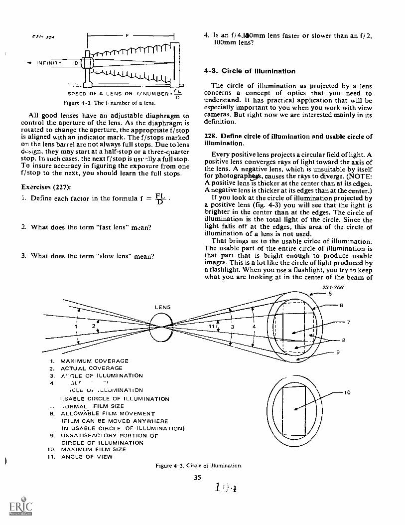
SPEED OF A LENS OR f/NUMBER
Figure 4-2. The f , number of a lens.
All good lenses have an adjustable diaphragm tocontrol the aperture of the lens. As the diaphragm isrmated to change the aperture, the appropriate f/ stopis aligned with an indicator mark. The f / stops markedon the lens barrel are not always full stops. Due to lens&sign, they may start at a half-stop or a three-quarterstop. In such cases, the next f/ stop is usu -Illy a full stop.To insure accuracy in figuring the exposure from onef/ stop to the next, you should learn the full stops.
Exercises (227):FLi. Define each factor in the formula f =
2. What does the term "fast lens" tn,tan?
3. What does the term "slow lens" mean?
4. Is an f/ 4.160mm lens faster or slower than an f/ 2,100mm lens?
4-3. Circle of Illumination
The circle of illumination as projected by a lensconcerns a concept of optics that you need tounderstand. It has practical application that will beespecially important to you when you work with viewcameras. But right now we are interested mainly in itsdefinition.
228. Define circle of illumination and usable circle ofillumination.
Every positive lens projects a circular field of light. Apositive lens converges rays of light toward the axis ofthe lens. A negative lens, which is unsuitable by itselffor photograph.54, causes the rays to diverge. (NOTE:A positive lens is thicker at the center than at its edges.A negative lens is thicker at its edges than at the center.)
If you look at the circle of illumination projected bya positive lens (fig. 4-3) you will see that the iight isbrighter in the center than at the edges. The circle ofillumination is the total light of the circle. Since thelight falls off at the edges, this area of the circle ofillumination of a lens is not used.
That brings us to the usable cirlce of illumination.The usable part of the entire circle of illumination isthat part that is bright enough to produce usableimages. This is a lot like the circle of light produced bya flashlight. When you use a flashlight, you try to keepwhat you are looking at in the center of the beam of
231-3065
1. MAXIMUM COVERAGE2. ACTUAL COVERAGE3. A'',LE OF ILLUMI NATION4 Cit.r
%CUL Ur ,L_LuMINATIONJSABLE CIRCLE OF ILLUMINATION
.-JIRMAL FILM SIZEB. ALLOWA-BLE FILM MOVEMENT
(FILM CAN BE MOVED ANYWHEREIN USABLE CIRCLE OF ILLUMINATION)
9. UNSATISFACTORY PORTION OFCIRCLE OF ILLUMINATION
10. MAXIMUM FILM SIZE11. ANGLE OF VIEW
Figure 4-3. Circle of illumination.
35
o
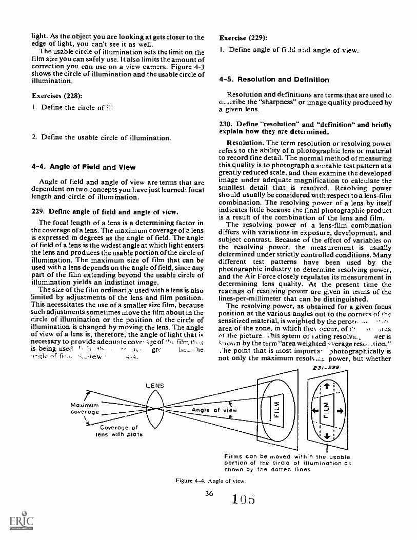
light. As the object you are looking at gets closer to theedge of light, you can't see it as well.
The usable circle of illumination sets the limit on thefilm size you can safely use. It also limits the amount ofcorrection you can use on a view camera. Figure 4-3shows the circle of illumination and the usable circle ofillumination.
Exercises (228):
I. Define the circle of
2. Define the usable circle of illumination.
4-4. Angle of Field and View
Angle of field and angle of view are terms that aredependent on two concepts you have just learned: focallength and circle of illumination.
229. Define angle of field and angle of view.The focal length of a lens is a determining factor in
the coverage of a lens. The maximum coverage of a lensis expressed in degrees as the angle of field. The angleof field of a lens is the widest angle at which light entersthe lens and produces the usable portion of the circle ofillumination. The maximum size of film that can beused with a lens depends on the angle of field, since anypart of the film extending beyond the usable circle ofillumination yields an indistinct image.
The size of the film ordinarily used with a lens is alsolimited by adjustments of the lens and film position.This necessitates the use of a smaller size film, becausesuch adjustments sometimes move the film about in thecircle of illumination or the position of the circle ofillumination is changed by moving the lens. The angleof view of a lens is, therefore, the angle of light that it;necessary to provide adequn te cove ;e of filmis being used r, - gr:. .bal. he
of 4-4.
LENS
Exerdse (229):
I. Define angle of fv.ld and angle of view.
4-5. Resolution and Definition
Resolution and definitions are terms that are used toucribe the "sharpness" or image quality produced bya given lens.
230. Define "resolution" and "definition" and brieflyexplain how they are determined.
Resolution. The term resolution or resolving powerrefers to the ability of a photographic lens or materialto record fine detail. The normal method of measuringthis quality is to photograph a suitable test pattern at agreatiy reduced scale, and then examine the developedimage under adequate magnification to calculate thesmallest detail that is resolved. Resolving powershould usually be considered with respect to a lens-filmcombination. The resolving power of a lens by itselfindicates little because Lhe final photographic productis a result of the combination of the lens and film.
The resolving power of a lens-film combinationdiffers with variations in exposure, development, andsubject contrast. Because of the effect of variables onthe resolving power. the measurement is usuallydetermined under strictly controlled conditions. Manydifferent test patterns have been used by thephotographic industry to determine resolving power,and the Air Force closely regulates its measurement indetermining lens quality. At the present time thereatings of resolving power are given in terms of thelines-per-millimeter that can be distinguished.
The resolving power, as obtained for a given focusposition at the various angles out to the corners of thesensitized material, is weighted by the percer "area of the zone, in which the 's. occur, oft',ot the picture. L his sytem of xating resolvi.., .ver isk 10,4% n by the term "area weighted .verage resu. .tion.";he point that is most importa photographically isnot only the maximum resoh...L1... power, but whether
23/_299
Maximumcoverage
Coverage oflens with plate
Films can be movedportion of the circleshown by the dolled
Figure 4-4. Angle of view.
36.1 0 6
within the usableof illumination aslines
the resolving power is ample over the entire format andover the range of densities or tones that are to berecorded when making the negative.
Definition. The term "photographic definition"refers to the quality aspect of a photograph that isassociated with the clarity of detail. Sincephotographic definition is impression made on themind of an observer when e views a photograph, theconcept of definition becomes subjective and dependson the viewer. Definition is a composite effect of atleast four factors:
Resolving power.Sharpness.Graininess.Tone reproduction.
Exercises (230):
I. Define resolving power and briefly describe how itis calculated.
2. Define definition and briefly describe how it isdetermined.
4-6. Coating
The coating on the surface of a lens affects its abilityto resolve fine detail. Different manufacturers proudlyexclaim the virtues of their lenses, and how well theircoatings improve performance. You don't need to beable to rebut any of these claims, but you should befamiliar with lens design characteristics.
231. Describe the purpose of a lens coating and theproper cleaning procedures necessary to preserve thecoating.
For many years, it had been known that old lensesthat had become tarnished with a bluish coatingactually transmitted more light than new lenses. It isnow common practice to coat lenses with a layer orlayers of special coating that minimize internalreflections, thereby reducing optical flare (reflectionsoff the glass surfaces of the lens) and improvingtransmission. By examining the front of a lens you willnotice a slight color tinge (blue, yellow, etc.); this iscaused by the lens coating used by the particularmanufacturer.
Proper cleaning procedures should be observed toinsure that this lens coating is not rubbed off. To cleana lens, first brush the surface with a fine brush toremove any foreign particles, then gently wipe thesurface with a seft--eletirey photographic lens tissue(not lens tissue for eyeglasses or wiping your nose),moistened with a recommended lens cleaner. +be-lowegip11-fhen.40-404isheiPIiviao=a=c1=rteis. The keythroughout the cleaning procedure is to avoid undue
37
Pressure or a hard rubbing action along the surface ofthe lens.Exercises (231):
I. What is the purpose of coating a lens?
2. How should you clean a lens to prevent destructionof the lens coating?
4-7. Normal Focal Length LensToday, the photographer has a tremendous number
of lenses to choose from to achieve the results he wants.Yet every camera comes with a "normal" lens.
132. Specify the rule for calculating the focal length ofa nornial lens.
The normal lens is considered to have a focal lengththat is about equal to the diagonal dimension of thefilm being used. The angle of coverage of a normal lensis approximately 45°. Normal lenses are usually thelastest" lenses that are available and are thereforeused for available light work. For the followingstandard film sizes, the following focal lengths areconsidered "normal."
Film Si=e35mm120 (producing 2 x 21/2 image)120 (producing 21/2 x 2114 image)4 x 58 x 10
No;nial FocalLength
50mm80mm901
150mm300mm
Exercise (232):
I. What is the rule for calculating the focal length of anormal lens?
4-8. Wide Angle LensThe wide angle lens has a shorter-than-normal focal
length. That is, the focal length is less than the diagonaldimension of the film that is being used. Wide anglelenses have characteristics which you should be awareof.
233. Specify characteristics associated with the wideangle lens.
One of the main advantages of the wide angle lens isthat it c rs a wider subject area than that covered bya norm. focal length lens at a given lens-to-subjectdistance. Typically, wide angle lenses cover from about60° up to 180° for so-called "fisheye" lenses. Thisfeature makes a wide angle lens the choice when youhave a short lens-to-subject distance and you want toinclude as much of the subject as possible in thepicture. Another advantage is that a wide angle lens
has greater depth of field than the normal lens whenboth are used at the same lens-to-subject distance andaperture. This feature has made the wide angle lens afavorite of many photojournalists. They stop downtheir wide angle lens to a moderate aperture (forinstance, f, 11) to insure adequate depth of field at theaverage lens-to-subject distance the, are using. Thenthey rely on depth of field ("zone focus") for sharpnessrather than focusing each shot during fast movingevents.
The advantages of the w :de angle also create someproblems to be considered. The wide angle coverageoften produces a challenge to compose all of thepicture elements effectively. Many beginningphotographers choose a wide angle lens because theycan get more in their pictures. This often leads tocompositions that are confusing because of an absenceof a strong point of interest. This is particularly truesince the relative subject size is smaller as compared toa longer focal length lens at the same shooting distance.In addition, the wide angle creates distortions resultingin elongation or curving of lines that may not bepleasing. Also, because of the complex nature of manywide angle designs, the lenses tend to be sharper in thecenter than at the edges. This necessitates stoppingdown the lens a couple of f/ stops to insure bettersharpness.
Taking all these things into consideration, the wideangle lens can be very effective when shooting incramped quarters, when covering fast breaking newsevents, when photographing scenics, and for obtainingan overall shot of the scene (establishing shot).
Exercise (233):
I. Complete the following statements on thecharacteristics of wide angle lenses.a. Wide angle lenses have than
normal focal lengths.b. At a given lens-to-subject distance, the subject
will appear when using a wideangle lens than one with a longer focal length.
c. At a given aperture and lens-to-subject distance,you will obtain morewhen using a wide angle lens than when using anormal lens.
d. Generally speaking, wide angle lenses aresharper in the than at the
4-9. Long-Focal-Length LensesNow that you have become familiar with normal and
wide angle lenses, you will learn about long-focal-length lenses.
234. Give selected characteristics of long-focal-lengthlenses.
Long focal length refers to any lens that has a focallength greater than normal (i.e., greater than thediagonal dimension of the film) and relies on this factto produce a large image size. Such lenses do not have
to be of special design but are often the result of takinga lens designed for a larger camera and using it oncamera having smaller film size. For example, you maybe using a 4 x 5 press camera that is normally equippedwith a 150mm lens. If this lens were replaced by a300mm lens used on an 8 x 10 camera, the 300mm lenswould be a long-focal-length lens on the 4 x 5 camera.(It is pointed out in the next section that a telephotolens achieves the long-focal-length effect throughspecial design.)
The advantage of a long-fo:ml-length lens is like atelescope, that it has a narrower angle of coverage(about 350 or narrower), and produces a larger imagesize than a normal lens at the same lens-to-subjectdistance. This makes the lens idedfor portraits, sports,photography, and nature photography. Such a long-reaching lens makes it easier for the beginner to isolatehis subject to achieve better composition.
There are disadvantages to using a long-focal-lengthlens. One problem is that unless the lens was designedfor the camera that is being used, it may be difficult toattach properly. The size and weight of the lens maychange the balance of the camera and require propertripod support. Rigidity is further required becausecamera-movement is magnified by this type of lens.Long-focal-length lenses are slow and require usinghigh speed film or supplementary lights. Finally, thedepth of field of a long-focal-length lens is inherentlyless at a given aperture than a normal or wide angle lensat the same lens-to-subject distances. This problem iscompounded by the fact that fast shutter speeds neededto prevent camera shake exclude small apertures.
NOTE: Long-focal-length lenses are primarilyapplicable to view and press cameras that use bellowsfor focusing and lens boards to interchange lenses.These features permit the interchange of lensesdesigned for different film formats which does notapply to small cameras.
Exercises (234):
1. How would you define a long-focal-length lens?
2. Why is it easier to achieve better composition withthe long-focal-length lens as compared with shorterlenses?
3. Why do you need to use high shutter speed:, whenphotographing with a long-focal-length lens?
4-10. Telephoto Lenses
Though the terms telephoto and long focal lengthhave been used interchangeably, the term telephoto isproperly applied only to lenses that have a particularoptical design. Telephoto lenses have become the
38 1 0
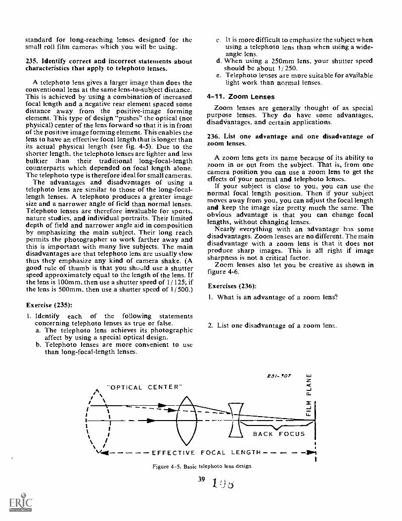
standard for long-reaching lenses designed for thesmall roll film cameras which you will be using.
235. Identify correct and incorrect statements aboutcharacteristics that apply to telephoto lenses.
A telephoto lens gives a larger image than does theconventional lens at the same lens-to-subject distance.This is achieved by using a combination of increasedfocal length and a negative rear element spaced somedistance away from the positive-image formingelement. This type of design "pushes" the optical (notphysical) center of the lens forward so that it is in frontof the positive image forming element. This enables thelens to have an effective focal length that is longer thanits actual physical length (see fig. 4-5). Due to theshorter length, the telephoto lenses are lighter and lessbulkier than their traditional long-focal-lengthcounterparts which depended on focal length alone.The telephoto type is therefore ideal for small cameras.
The advantages and disadvantages of using atelephoto lens are similar to those of the long-focal-length lenses. A telephoto produces a greater imagesize and a narrower angle of field than normal lenses.Telephoto lenses are therefore invaluable for sports,nature studies, and individual portraits. Their limiteddepth of field and narrower angle aid in compositionby emphasizing the main subject. Their long reachpermits the photographer to work farther away andthis is important with many live subjects. The maindisadvantages are that telephoto lens are usually slowthus they emphasize any kind of camera shake. (Agood rule of thumb is that you should use a shutterspeed approximately equal to the length of the lens. Ifthe lens is 100mm, then use a shutter speed of 1/ 125; ifthe lens is 500mm, then use a shutter speed of 1/ 500.)
Exercise (235):
I. Identify each of the following statementsconcerning telephoto lenses as true or false.a. The telephoto lens achieves its photographic
affect by using a special optical design.b. Telephoto lenses are more convenient to use
than long-focal-length lenses.
AiL**OPTICAL CENTER-
It is more difficult to emphasize the subject whenusing a telephoto lens than when using a wide-angle lens.
d When using a 250mm lens, your shutter speedshould be about 1/ 250.
e. Telephoto lenses are more suitable for availablelight work than normal lenses.
4-11. Zoom LensesZoom lenses are generally thought of as special
purpose lenses. They do have some advantages,disach;antages, and certain applications.
236. List one advantage and one disadvantage ofzoom lenses.
A zoom lens gets its name because of its ability tozoom in or out from the subject. That is, from onecamera position you can use a zoom lens to get theeffects of your normal and telephoto lenses.
If your subject is close to you, you can use thenormal focal length position. Then if your subjectmoves away from you, you can adjust the focal lengthand keep the image size pretty much the same. Theobvious advantage is that you can change focallengths, without changing lenses.
Nearly everything with an advantage has somedisadvantages. Zoom lenses are no different. The maindisadvantage with a zoom lens is that it does notproduce sharp images. This is all right if imagesharpness is not a critical factor.
Zoom lenses also let you be creative as shown infigure 4-6.
Exercises (236):
I. What is an advantage of a zoom lens?
2. List one disadvantage of a zoom lens.
23/ - 307 La
-Ja_
- EFFECTIVE FOCAL LENGTH
Figure 4-5. Basic telephoto lens design
391 ',I ;S
,sts'c
-'111116;,
,I
4-12. Image Size Control
sti,.,4
'
.
*,
Figure 4-6. Zoom lens effect.
4-13. PerspectiveAs a photograph r, yon need to carefully consider
the relative size of your subject and other pictureelements. Not only is this an important aspect ofcomposition, but it is also a vital element throughoutthe reproduction cycle.
237. Describe the two photographic controls that areused to determine image size.
Given a particular film format, two factors thatcontrol image size are focal length of the lens and thelens-to-subject distance. The longer the focal length,the larger the image on the film for a given lens-to-subject distance. Therefore, by using a camera with aninterchangeable lens capability and by having aselection of lenses, the photographer can control imagesize for any given shooting distance. Conversely, forany given focal length of lens, the closer you are to thesubject, the bigger the image will be. (Unfortunately,many lenses do not focus closer than a couple of feetfrom the subject.) You should, therefore, alwaysbalance between shooting distance and focal length toachieve the results you want.Exercise (237):
1. Identify and describe the two controls that can beus-A to determine image size.
You can see objects in three dimensions, but a lensforms images in only two dimensions (height andwidth). The missing dimension, depth, is suggested bythe relative position and size of the objects in tneimage. Foreground objects are large, and backgroundobjects appear smaller. The relation of these objects,called perspective, is of considerable importancebecause it controls the naturalness of the picture,
238. Define perspective.
Again, let us define perspective. It is the impressionof depth when a 3-dimensional scene is represented in a2-dimensional photograph. We are trying to make adistinction between perspective and perception. Theperspective is there when you position the camera,That is, things close to the camera will appear to beclose in the finished picture. The only way to makethem appear to be far away is to move the camera.
Nothing will change the relative perspective.However, focal length of the lens can change yourperception For instance, recall the telephoto shot of abaseball pitcher 0 .1* catcher you see on theSaturday ballgame" Yob c'an tell that the catcher isfarther away than the pitcher. But because of the longfocal length your perception is changed. It nowappears as though the pitcher and catcher can shakehands.
The change of lenses will change image size but willnot change the relative position of the pitcher and
40
10J
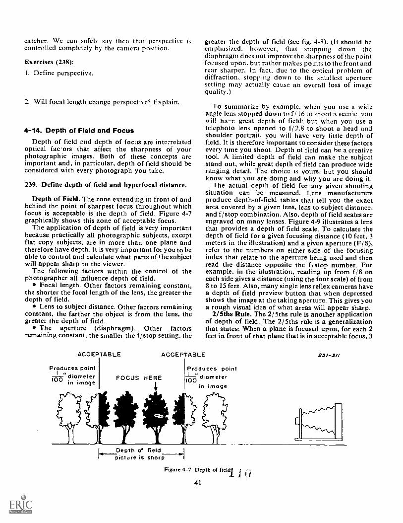
catcher. We can safely say then that perspectivecontrolled completely by the camera position.
is greater the depth of field (see fig. 4-8). (It should beemphasized, however, that stopping down thediaphragm does not improve the sharpness of the pointfocused upon. but rather makes points to the front andrear sharper. In fact, due to the optical problem ofdiffraction, stopping down to the smallest aperturesetting may actually cause an overall loss of imagequality.)
Exercises (238):
I. Define perspective.
2. Will focal length change perspective? Explain.
4-14. Depth of Field and FocusDepth of field end depth of focus are inte..-related
optical fac'ors that affect the sharpness of yourphotographic images. Both of these concepts areimportant and, in particular, depth of field should beconsidered with every photograph you take.
239. Define depth of field and hyperfocal distance.
Depth of Field. The zone extending in front of andbehind the point of sharpest focus throughout whichfocus is acceptable is the depth of field. Figure 4-7graphically shows this zone of acceptable focus.
The application of depth of field is very importantbecause practically all photographic subjects, exceptflat copy subjects, are in more than one plane andtherefore have depth. It is very important for you to beable to control and calculate what parts of the subjectwill appear sharp to the viewer.
The following factors within the control of thephotographer all influence depth of field.
e Focal length. Other factors remaining constant,the shorter the focal length of the lens, the greater thedepth of field.
Lens to subject distance. Other factors remainingconstant, the farther the object is from the lens, thegreater the depth of field.
The aperture (diaphragm). Other factorsremaining constant, the smaller the f/ stop setting, the
To summarize by example. when you use a wideangle lens stopped down to f/ 16 to choot a scenic, youwill ha-e great depth of field; but when you use atelephoto lens opened to f/ 2.8 to shoot a head andshoulder portrait. you will have very little depth offield. It is therefore important to consider these factorsevery time you shoot. Depth of field can be a creativetool. A limited depth of field can make the subjcetstand out, while great depth of field can produce wideranging detail. The choice is yours, but you shouldknow what you are doing and why you are doing it.
The actual depth of field for any given shootingsituation can oe measured. Lens manufacturersproduce depth-of-field tables that tell you the exactarea covered by a given lens, lens to subject distance.and f/stop combination. Also, depth of field scales areengraved on many lenses. Figure 4-9 illustrates a lensthat provides a depth of field scale. To calculate thedepth of field for a given focusing distance (10 feet, 3meters in the illustration) and a given aperture (F/ 3),refer to the numbers on either side of the focusingindex that relate to the aperture being used and thenread the distance opposite the f/stop number. Forexample, in the iilustration, reading up from f/ 8 oneach side gives a distance (using the foot scale) of from8 to 15 feet. Also, many single lens reflex cameras havea depth of field preview button that when depressedshows the image at the taking aperture. This gives youa rough visual idea of what areas will appear sharp.
2/5ths Rule. The 2/ 5ths rule is another applicationof depth of field. The 2/ 5ths rule is a generalizationthat states: When a plane is focused upon, for each 2feet in front of that plane that is in acceptable focus, 3
ACCEPTABLE ACCEPTABLE
Produces pointdiameter100 in image
FOCUS HEREProduces point
"diameter100in image
L. Depth of fieldpicture is sharp
2.51-3/1
Figure 4-7. Depth of fieldl1
r-1 t
41
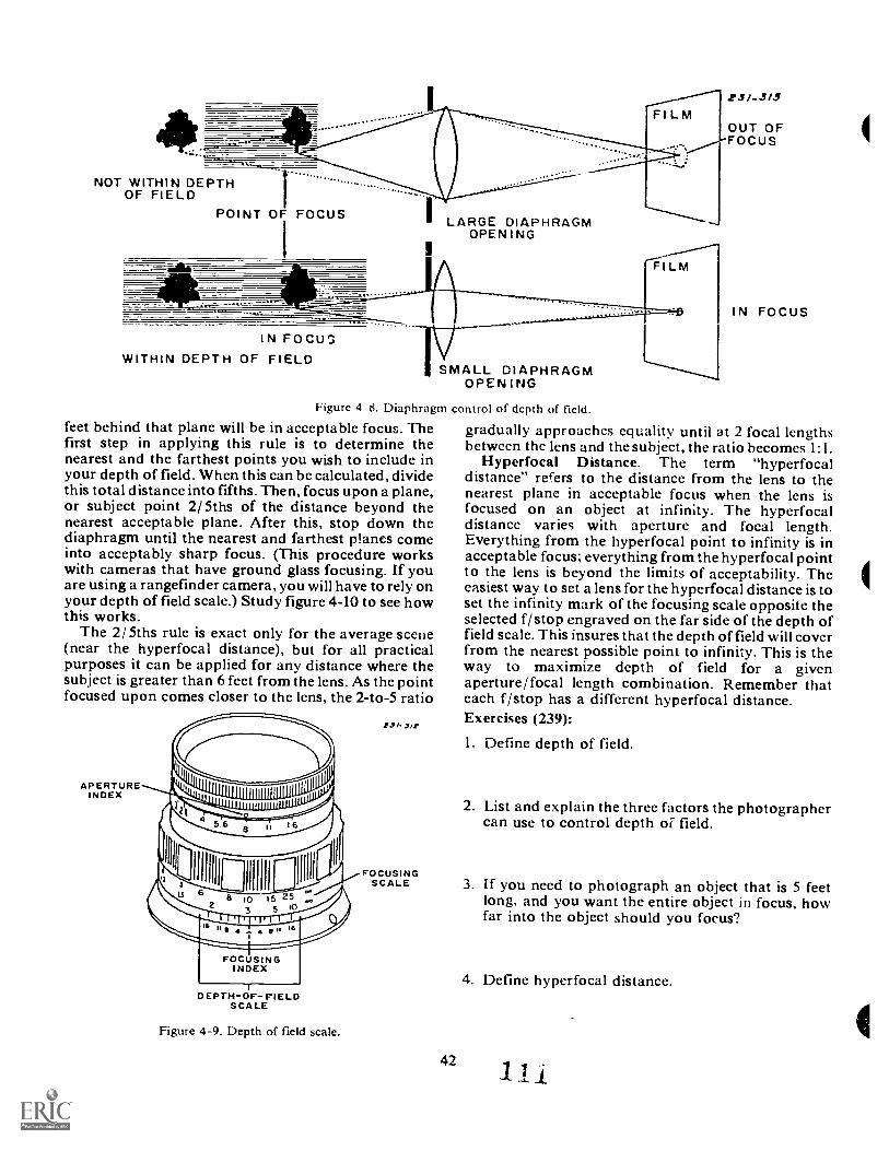
Fl LM
OF FIELDNOT WITHIN DEPTH
POINT OF FOCUS
1
LARGE DIAPHRAGMOPENING
FILM
IN FOCUSWITHIN DEPTH OF FIELD
SMALL DIAPHRAGMOPENING
Figure 4 8. Diaphragm control of depth of field.
feet behind that plane will be in acceptable focus. Thefirst step in applying this rule is to determine thenearest and the farthest points you wish to include inyour depth of field. When this can be calculated, dividethis total distance into fifths. Then, focus upon a plane,or subject point 2/ 5ths of the distance beyond thenearest acceptable plane. After this, stop down thediaphragm until the nearest and farthest planes comeinto acceptably sharp focus. (This procedure workswith cameras that have ground glass focusing. If youare using a rangefinder camera, you will have to rely onyour depth of field scale.) Study figure 4-10 to see howthis works.
The 2/ 5ths rule is exact only for the average scene(near the hyperfocal distance), but for all practicalpurposes it can be applied for any distance where thesubject is greater than 6 feet from the lens. As the pointfocused upon comes closer to the lens, the 2-to-5 ratio
APERTUREINDEX
411110
2
6
...r
111111
II
a 103
5 25110
5 10
II 16
FOCUSINGINDEX
co
DEPTH-OF- FIELDSCALE
Figure 4-9. Depth of field scale.
4.5/.5/1,
FOCUSINGSCALE
42
231-3/5
OUT OFFOCUS
IN FOCUS
gradually approaches equality until at 2 focal lengthsbetween the lens and the subject, the ratio becomes 1:1.
Hyperfocal Distance. The term "hyperfocaldistance" refers to the distance from the lens to thenearest plane in acceptable focus when the lens isfocused on an object at infinity. The hyperfocaldistance varies with aperture and focal length.Everything from the hyperfocal point to infinity is inacceptable focus; everything from the hyperfocal pointto the lens is beyond the limits of acceptability. Theeasiest way to set a lens for the hyperfocal distance is toset the infinity mark of the focusing scale opposite theselected f/ stop engraved on the far side of the depth offield scale. This insures that the depth of field will coverfrom the nearest possible point to infinity. This is theway to maximize depth of field for a givenaperture/focal length combination. Remember thateach f/stop has a different hyperfocal distance.Exercises (239):
1. Define depth of field.
2. List and explain the three factors the photographercan use to control depth of field.
3. If you need to photograph an object that is 5 feetlong, and you want the entire object in focus, howfar into the object should you focus?
4. Define hyperfocal distance.
1
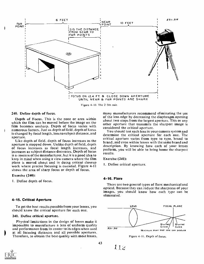
FARPOINT
6 FEET'NEAR 10 FEETPOINT .1,y-
' 2/5 THE DISTANCE:FROM NEAR TO'FAR POINTS
FOr:US ON 12.4 FT. & CLOSE DOWN APERTUREUNTIL NEAR a FAR POINTS ARE SHARP
Figure 410. The 2/5th rule.
240. Define depth of focus.
Depth of Focus. This is the zone or area withinwhich the film can be moved before the image on thefilm becomes unsharp. Depth of focus varies withnumerous factors. Just as depth of field, depth of focusis changed by focal length, lens to subject distance, andaperture.
Like depth of field, depth of focus increases as theaperture is stopped down. Unlike depth of field, depthof focus increases as focal length increases, andincreases as subject distance decreases. Depth of focusis a (:oncern of the manufacturer, but it is a good idea tokeep in mind when using a view camera where the filmplane is moved about and in doing critical closeupwork where precise focusing is essential. Figure 4-11shows the area of sharp focus or depth of focus.Exercise (240):
I. Define depth of focus.
4-15. Critical Aperture
To get the best results possible from your lenses, youshould know the critical aperture for each one.
241. Define critical aperture.
Physical limitations in the design of lenses make itimpossible to manufacture a lens of uniform qualityand performance from its center to its edges when usedat all focusing distances and all possible apertures.Therefore, to obtain the best quality with most lenses,
43
Z.5/-3/6
many manufacturers recommend eliminating the useof the lens edge by decreasing the diaphragm openingabout two stops from the largest aperture. This or anyother aperture that transmits the sharpest image isconsidered the critical aperture.
You should test each lens in your camera system anddetermine the critical aperture for each one. Thecritical aperture varies from type to type, brand tobrand, and even within lenses with the same brand anddescription. By knowing how each of your lensesperform, you will be able to bring home the sharpestresults.
Exercise (241):
I. Define critical aperture.
4-16. Flare
There are two general types of flare: mechanical andoptical. Because they can reduce the sharpness of yourimages, you should know how each type can beeliminated.
LENS
231- 310
I
FOCAL PLANE
Blurred BlurredCircle Circle
Minimum blurr that lens can produce
Figure 4-11. Depth of focus.
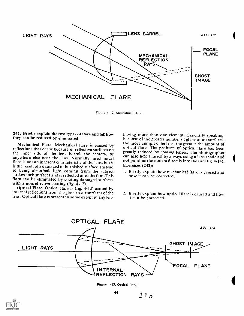
LIGHT RAYS LENS BARREL
MECHANICALREFLECTION
R AYS
MECHANICAL FLARE
Figure 4 12. Mechanical flare.
242. Briefly explain the two types of flare and tel: howthey can be reduced or eliminated.
Mechanical Flare. Mechanical flare is caused byreflections that occur because of reflective surfaces onthe inner side of the lens barrel, the camera, oranywhere else near the lens. Normally, mechanicalflare is not an inherent characteristic of the lens, but itis the result of a damaged or burnished surface. Insteadof being absorbed, light coming from the subjectstrikes such surfaces and is reflected onto the film. Thisflare can be eliminated by coating damaged surfaceswith a nonreflective coating (fig. 4-12).
Optical Flare. Optical flare is (fig. 4-13) caused byinternal reflections from the glass-to-air surfaces of thelens. Optical flare is present to some extent in any lens
23/ - 3/7
FOCALPLANE
GHOSTI MAGE
having more than one element. Generally speaking,because of the greater number of glass-to-air surfaces,the more complex the lens, the greater the amount ofoptical flare. The problem of optical flare has beengreatly reduced by coating lenses. The photographercan also help himself by always using a lens shade andnot pointing the camera directly into the sun (fig. 4-14).Exercises (242):1. Briefly explain how mechanical flare is caused and
how it can be corrected.
2. Briefly explain how optical flare is caused and howit can be corrected.
OPTICAL FLARE
LIGHT RAYS
INTERNALREFLECTION RAY S
Figure 4-13. Optical flare.
4411 3
23/- 3/8
GHOST IMAGE
XFOCAL PLANE
-4...k.
Figure Example of optical. flare.4-14.
45 114
-
CHAPTER 5
Photographic FiltersAN AIRMAN WHO was in need of a new suit wentinto the local clothing store. The salesman showed theairman several suits. Finally the airman said, "This is afine suit, but don't you have one like it in blue"?
"Blue!" said the salesman, "Harry, put a blue filterover the light; the man wants a blue suit."
In photography, filters are used to control the lightstriking the film. By effectively using filters, you canchange the relative contrast between colors. You canisolate, subdue, enhance, or eliminate a color by usingthe proper filter. Filters, when thoughtfully chosen,can help you achieve better quality in yourphotographic work (or even help you buy a blue suit.)
5-1. ConstructionFilters are primarily of two kindsdyed gelatin or
colored glass. Let us discuss the advantages and carefor both.
243. Specify specified characteristics of gelatin andglass filters.
Gelatin Filters. The simplest filter is a sheet of dyedgelatin that can be cut into pieces of the appropriatesize and held in front of the lens by a suitable holder.Gelatin filters are inexpensive and come in the widestvariety of colors. Thus, they are very popular forexperimentation, color photography, and for use withodd-size lenses. The main disadvantage of a gelatinfilter is that it is delicate. Scratches, discolored spots,and fingerprints will render the filter useless.
Glass Filters. Glass filters are made out of dyed glassor by using a sheet of dyed gelatin between two sheetsof glass. They come in a variety of sizes (designated inmillimeters or series) and types. A glass filter may beeither screwed into the front of the lens or held by aretaining ring (used for series filters). Glass filters aremore expensive and durable than gelatin filters but donot come in quite the variety of colors and densityranges. Each glass filter should be treated just like alens. Any lint or dust should be removed with a brush.Lens tissue moistened in lens cleaner should be used toremove fingerprints.
NOTE: All filters, regardless of the method ofmanufacture, fade with use. It is, therefore, a good ideato replace your filters at regular intervals.Exercises (243):
1. What are two advantages of using a gelatin filter?
46
2. What is the main advantage of a glass filter over agelatin filter?
3. In time, wllat happens to any filter?
5-2. Effects and Limitations
The photographic filter is an optical device forcontrolling the transmission of light to the film. Tounderstand the use of filters you apply what you knowabout the sensitivity of film and the color quality oflight. Using filters is easy and will greatly enhance yourphotographic work. In this section you will learn whata filter does to light.
244. Identify the color, absorption, and transmissionof different colored filters and for given conditions,identify likely problems in filter application.
White Light. White light or visible light is composedof blue, green, and red wavelengths of light. Thesethree colors are called the additive primary colorsbecause none of these can be created by anycombination of the other two. In addition, all three ofthese colors of light must be present to combine andcreate white light. If blue and green light are combinedin equal quantities, they form cyan. A combination ofblue and red light produces magenta, and green andred light combine to produce yellow. Cyan, magenta,and yellow are called subtractive primary colors.
The color star in figure 5-1 shows the additive andsubtractive primary colors in a logical arrangement.Notice that each color in the star has a color directlyopposite it. Colors on opposite sides of the color starare called complementary colors. When each of thecomplementary colors of iight are mixed in the correctproportion, they also produce white light. Magentaand green are complementary, and they can combineto form white light. Magenta is actually red and blue.When green is added, all three additive primary colorsare present and white light is formed. In the same way,red and cyan are complementary, and blue and yelloware complementary. To repeat, red, green, and bluelight combined in the correct proportions make whitelight.
Filter Application. By using a filter over a cameralens, we can employ what is known as sutractive colorfiltration. As this is explained, you should carefullystudy figure 5-2.
1.16
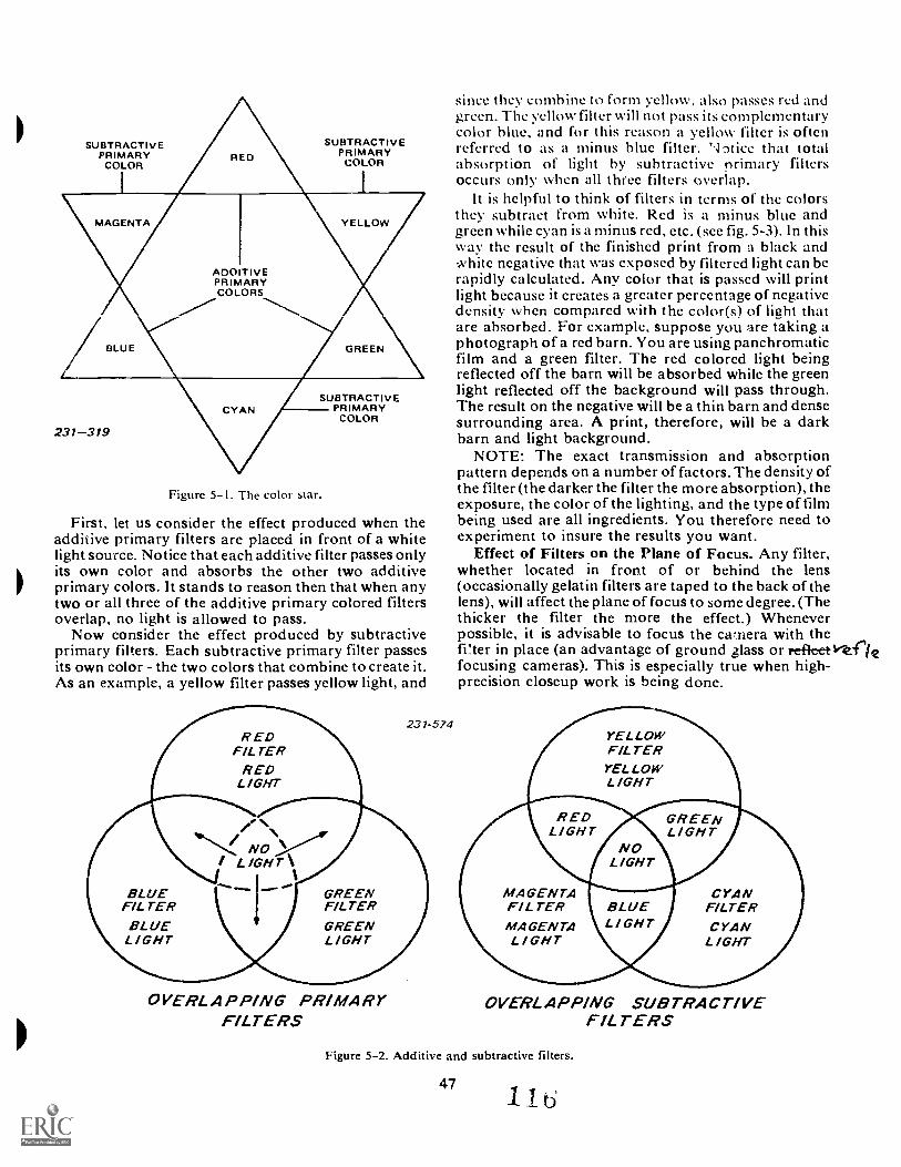
SUBTRACTIVEPRIMARY
COLOR
SUBTRACTIVEPRIMARYCOLOR
MAGENTA YELLOW
A00 TIVEPRIMARYCOLORS
Z. BLUE
231-319
GREEN
SUBTRACTIVEPRIMARY
COLOR
Figure 5-1. The color star.
First, let us consider the effect produced when theadditive primary filters are placed in front of a whitelight source. Notice that each additive filter passes onlyits own color and absorbs the other two additiveprimary colors. It stands to reason then that when anytwo or all three of the additive primary colored filtersoverlap, no light is allowed to pass.
Now consider the effect produced by subtractiveprimary filters. Each subtractive primary filter passesits own color - the two colors that combine to create it.As an example, a yellow filter passes yellow light, and
231-574R ED
FILTERRED
LIGHT
NOVA'I LIGHT\
since they combine to form yellow, also passes red andgreen. The yellow filter will not pass its complementarycolor blue, and for this reason a yellow filter is oftenreferred to as a minus blue filter. 'tice that totalabsorption of light by subtractive nrimary filtersoccurs only when all three filters overlap.
It is helpful to think of filters in terms of the colorsthey subtract from white. Red is a minus blue andgreen while cyan is a minus red, etc. (see fig. 5-3). In thisway the result of the finished print from a black andwhite negative that was exposed by filtered light can berapidly calculated. Any color that is passed will printlight because it creates a greater percentage of negativedensity when compared with the color(s) of lieht thatare absorbed. For example, suppose you are taking aphotograph of a red barn. You are using panchromaticfilm and a green filter. The red colored light beingreflected off the barn will be absorbed while the greenlight reflected off the background will pass through.The result on the negative will be a thin barn and densesurrounding area. A print, therefore, will be a darkbarn and light background.
NOTE: The exact transmission and absorptionpattern depends on a number of factors. The density ofthe filter (the darker the filter the more absorption), theexposure, the color of the lighting, and the type of filmbeing used are all ingredients. You therefore need toexperiment to insure the results you want.
Effect of Filters on the Plane of Focus. Any filter,whether located in front of or behind the lens(occasionally gelatin filters are taped to the back of thelens), will affect the plane of focus to some degree. (Thethicker the filter the more the effect.) Wheneverpossible, it is advisable to focus the cwnera with thefi!ter in place (an advantage of ground glass or refleetvt(.2focusing cameras). This is especially true when high-precision closeup work is being done.
R EDLIGHT
YELLOWF/LTERYELLOWLIGHT
NOLIGHT
GREENLIGHT
BLUE GREEN MAGENTA CYANFILTER FILTER FILTER BLUE FILTERBLUE GREEN MAGENTA LI GHT CYANLIGHT LIGHT LIGHT LIGHT
OVERLAPPING PRIMARYFILTERS
OVERLAPPING SUBTRACTIVEFlLT ERS
Figure 5-2. Additive and subtractive filters.
47b
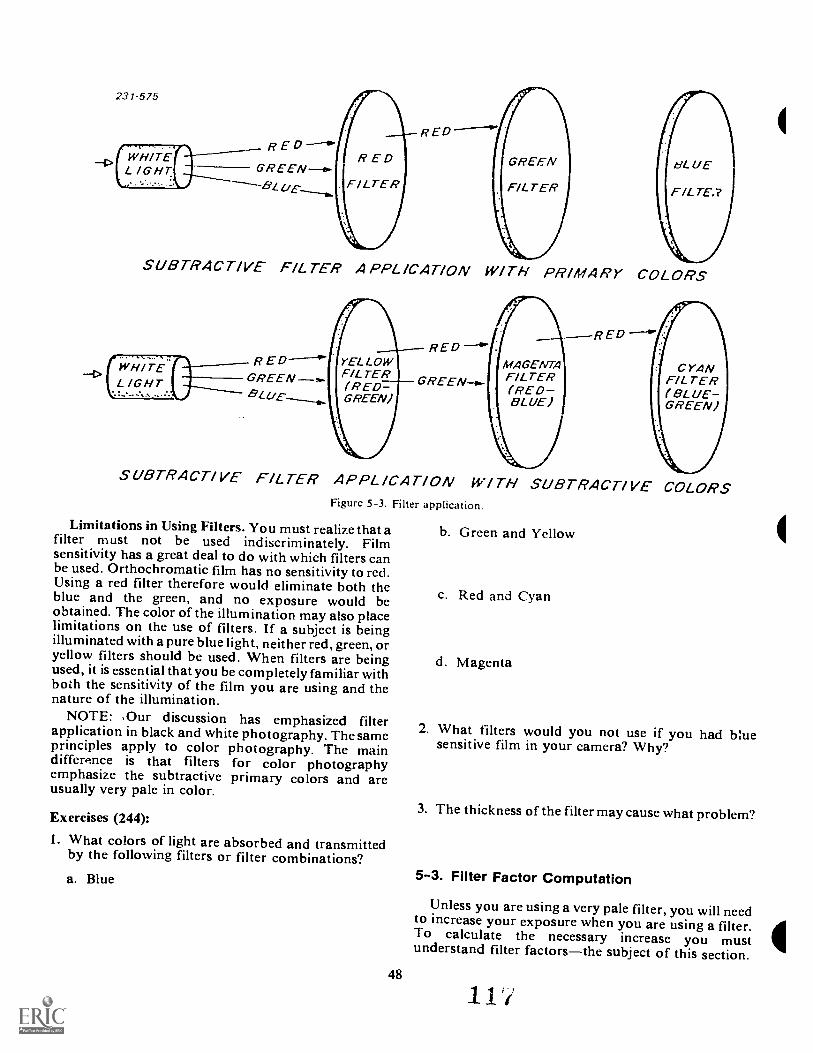
231-575
R E
-4> (LW76/ lir. ET(
R ED
SUBTRACTIVE FILTER APPLICATION WITH PRIMARY COLORS
SUBTRACTIVE FILTER APPLICATION WITH SUBTRACTIVEFigure 5-3. Filter application.
Limitations in Using Filters. You must realize that afilter must not be used indiscriminately. Filmsensitivity has a great deal to do with which filters canbe used. Orthochromatic film has no sensitivity to red.Using a red filter therefore would eliminate both theblue and the green, and no exposure would beobtained. The color of the illumination may also placelimitations on the use of filters. If a subject is beingilluminated with a pure blue light, neither red, green, oryellow filters should be used. When filters are beingused, it is essential that you be completely familiar withboth the sensitivity of the film you are using and thenature of the illumination.
NOTE: .Our discussion has emphasized filterapplication in black and white photography. The sameprinciples apply to color photography. The maindifference is that filters for color photographyemphasize the subtractive primary colors and areusually very pale in color.
Exercises (244):
1. What colors of light are absorbed and transmittedby the following filters or filter combinations?a. Blue
48
b. Green and Yellow
c. Red and Cyan
d. Magenta
COLORS
2. What filters would you not use if you had bluesensitive film in your camera? Why?
3. The thickness of the filter may cause what problem?
5-3. Filter Factor Computation
Unless you are using a very pale filter, you will needto increase your exposure when you are using a filter.To calculate the necessary increase you mustunderstand filter factorsthe subject of this section.
1 1
245. Solve exposure problems involving filter factors.
Since filters absorb light, the amount of exposuregiven with a filter must, in almost all cases, be greaterthan the exposure without a filter. How much theexposure must be increased depends upon the colorand density of the filter, the color sensitivity of the film,the color of the illumination that falls upon the subject,and the reflective properties of the subject.
The exposure increase necessary for each filter isgiven as a filter factor number. You can obtain thespecific filter factor for your film-filter combination byreading the data sheets supplied with the filter and filmy are using. Then there are three methods that can be
ed to calculate your next exposure.One way to use a factor is to divide the factor into the
ASA or exposure index of the film you are using andthen set your meter to this new figure. For example,with Kodak Tri-X Pan rated at ASA 400 and a light-green filter having a factor of 4, divide the filter factorinto the film speed to calculate the new exposure indexwhich is 100 (400 ÷ 4 = 100). Once you have set themeter at the new exposure index; you can use the meterin the normal manner. Remember, however, to resetthe meter to the original ASA setting when you are notusing the filter.
Another method of applying the filter factor isthrough the f/stop setting. Before applying thismethod, you must be thoroughly familiar with f/ stopand their function in changing exposure. The followingchart shows what the filter means when related tof; stops.
Filter Factor 2 4 6 8Increase f stop by I 2 .7Y2 3
As you can see from the chart, a filter factor of 2would require a one stop increase (doubling ofexposure) from the basic setting. This would mean thatif your exposure was f/ 8 at 1/ 125 and you decided touse a yellow filter with a factor of 2 your new F.:xposurewould be f/ 5.6 at 1/ 125.
A third and perhaps the easiest method tocompensate for the filter factor is to multiply theexposure time by the filter factor. For example, a basicexposure without a filter is I/ 500 at f/ 8. Afterinstalling a filter with a factor of 4, the new exposurewould be calculated as follows: 1/500 X 4/ 1 = 1/125.The f/ stop would remain the same.
Filter factors serve only as guides. The factors varyfrom manufacture, even with filters that appear to bethe same color. Since overexposure can kill the effectof a filter, it is a good idea to bracket your exposures byfull stops to make sure you get a satisfactory result.Exercises (245):1. Calculate the correct exposure for each of the
following filter problems.a. Suppose you are going to use a green filter with a
factor of 4. What would your new shutter speedbe if your basic exposure is f/ I I at I/ 500?
h. You are going to use a filter with a factor of 2.What would your new 1:stop be if your basicexposure i f 22 at 1 30?
c. Now you are planning to use a filter with a factorof 8. What would your new exposure index be ifyou were using a film with an ASA of 320?
5-4. Correction Filteal for Black and White
In this section you will learn how correction filterscan help you achieve more mitural tonal reproductionin your black and white work.
246. Identify from a list the correct filter/filmcombination that can be used to achieveorthochromatic rendition.
There are no black-and-white panchromaticemulsions with ;-xactly the same color sensitivity asthat of the human eye. The normal eye tends to be moresensitive to green, while panchromatic films arerelatively more sensitive to blue or in some cases to red.The purpose of a correction filter is to absorb a portionof the color of the light to which the film is mostsensitive. The film then reproduces the subject colors inshades of gray which, when printed, will correspondmore closely to the way the eye would have renderedthem. This type of result is called orthochromaticrendition.
The filter recommendations for correct rendering ofsubjects in black and white are oalinarily included inthe film data sheets. The two filters recommended byKodak for their panchromatic films are:
I. Daylight LightingNo. 8 (K2)MediumYellow
2. Tungsten LightingNo. 11 (X1)Light GreenThe medium yellow absorbs the excess blue that is
found in daylight and to which the film is already verysensitive. This cuts down density in the sky area and,therefore, renders the sky a light gray (rather thanwhite) in the print. The light green filter cuts down theexcess red found in tungsten lighting.
NOTE: Blue sensiti./e and orthochromatic filmscannot be used to achieve orthochromatic renditionbecause of their limited sensitivites.Exercise (246):
I. Pick out which one of the following film/filtercombinations can be used to achieveorthochromatic results in daylight lighting.a. Orthochromatic film and an orange filter.b. Panchromatic film and a red filter.c. Blue sensitive film and a red filter.d. Panchromatic film and a blue filter.e. Orthochromatic film and a yellow filter.f. Panchromatic film and a yellow filter.
49

5-5. Contrast FiltersContrast filters are stronger than correction filters.
Their purpose is to create tonal separation betweentwo colors that otherwise would appear as the sameshade of gray or to create exaggerated tonal effects.Proper use of contrast filters can make your black -and-white work more dramatic and interesting.
247. Describe the effect of using selected contrastfilters in different shooting situations.
Contrast filters come in a variety of colors anddensities. They are identified in different ways by theirmanufacturers. Let us discuss the effect that a varietyof contrast filters haN e in black and whitephotography.
Yellow. A yellow filter, as has been mentioned, canbe used as a correction filter. It is a minus blue filterwhich is used to make the sky appear darker in a print.Yellow filters can be found in light, medium, and darkdensities. The darker the filter the more blue that isabsorbed. The medium yellow filter is probably thebest all around filter for daylight black and whitephotography.
Orange. An orange fil' -r absorbs more blue than ayellow one, therefore, it produces dramatic(exaggerated) contrast between sky and clouds. It canbe ideal for beach and snow scenes where greaterfiltration of blue may be desired. It is also effective forpictures of furniture made of yellowish woods likemaple, oak, or walnut.
lemmea__
Ad&
Red, A red filter is a very strong primary filter. Itabsorbs a great deal of blue. It can create spectacularcloud shots as it can render the sky almost black onthe print. For the same reason, it is good forarchitecture shots of light-tone buildings as they can bemade to stand out dramatically against a darkened sky."Fake- night shots can be made by underexposing withthe red filter. A red filter (along with orange) is notusually suitable for portraiture, particularly of women,as it leads to chalky skin tones.
Green. A green filter is excellent for outdoor scenes3 it increases the contrast between sky and clouds and
lightens foliage, bringing out greater detail. In flowerphotography it is effective because it often lightem theleaves while darkening the flowers. A green filter is bestfor outdoor portraiture as it renders skin tonescorrectly. It can also be used to render the red lipstickof a girl darker.
Blue. A rarely used filter as it increases the density ofblue relative to the other primary colors. It is usedoccasionally to create a "hazy" sky which can havepictorial value as it produces a greater feeling of depth.
Filters are very effective tools in black and whitephotography. They can create effective tonaldifferences that could otherwise only be accomplishedby very tedious printing techniques. Look at figures 5-4, 5-5, 5-6, 5-7, and 5-8 to see how subjects can berendered using different filters. Filters are easy to use.You can examine the scene through the filter to getsome idea of its effect. Through practice you will knowwhich filter will help you get the result you want.
Figure 5-4. Normal picture,
50
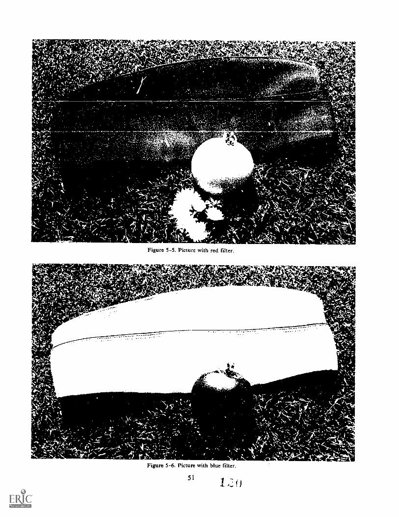
. ' , "-e- 4 df/ IN71../-
r-% 1:,
*,- - A4
\.-
- A!'-'
$
; .r, ....k.... - ,.. 4 VI: .... . . - . .44_ .,
, 1; 4!,.s..,,..., ... 'No "I '':-.--' 7. -7,--kt
1 v --- -- --.., !.
<
'-.,\4 ,.=.1, . -')C7:-.*.1..,,,-,,..t .\ f .4. - ,!.I 1. . r . ,
4 y ' ,.."`IVI:','..,, -- 1 ..c.",
%,,- ,-1,1 .., 1 , '. , r. T., - . . - ...,....
i v-r A' - 1 -CL,' a 1 ; ';'.. i ' % ' .. - . , . A 4 ,.
, !..,: s.), ,,,, LN..,,,,t, , ,...A, A ..v.,,,...,,, 4 v: .4 ....t ,
f , '' ;.\ ,. i r 't-ii., A ;' ... 1" . it ,".1.. - '. V , Vk, ,.....\\_\ -:,,.... '
Figure 5-5. Picture with red filter.
Figure 5-6. Picture with blue filter.
5 1
1
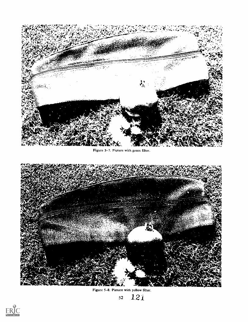
4e--
if(t.41
,#:1411,#
4
-,
ez-k-e:
Figure 5-7. Picture with green filter,
;.- 4wv -;e-eigt-
--\
-
ik
tz; s2
'4 134.SY"..- ".%kcY;:4,$tcffet.1*!1/44W:::6-:47'`.4/464/t71:
0> %Aka--.,oe_f
_; s
IP:. ...t
Figure 5-8. Picture with yellow filter.
52 1 21
41116.
A
Exercise (247):
I. Describe the final photographic print effect of usinga given filter in each of the following situations.a. You are photographing a red rose using a red
filt,r.
b. You are using a green filter when photographinga meadow on a sunny day.
c. You use an orange filter when photographingthe White House on a clear day.
d. Today you photograph a mountain scene with ablue filter.
5-6. Neutral Density Filters
Neutral density filters are another type of filter youshould become familiar with. A neutral density filtercan help you when you encounter high intensitylighting situations or when you want to achieve certaincompositional effects.
248. Briefly explain what a neutral density filter doesand how it can be used.
Neutral density (ND) filters come in differentdensities of gray. They are used to control the intensity,rather than the color, of light striking the film. Thereare two basic shooting situations where a neutraldensity filter comes in handy. The first is where thelight intensity is so strong that overexposure will resultwith the film that is being used. For example, yourcamera may be loaded with film rated at 1,000 ASAand you find yourself shooting at the beach on asunny day. Even if you use the highest shutter speedand the smallest aperture your camera has you stilloverexposed. The second situation is when the light istoo strong for slow shutter speeds or large aperturesettings that may be important for compositionalreasons. For example, you may need a large apertureto achieve limited depth of field when shooting aportrait or a slow shutter speed to give the feeling ofspeed when shooting an auto race. If it is a bright sunnyday and you have a moderate (ex. 400 ASA) speed filmin your camera, your selection of shutter speed andf/stop combinations may be limited. A neutral densityfilter in these situations can be used to preventoverexposure.
Neutral density filters are usually identified by theirdensity or filter factor. Here is an abbreviated list ofavailable neutral density filters.
Percent qfDensity Light Transmitted Filter Factor
97+3430.600.901.302.00
0, 3 0 50%25%13%5%
247.7
20100
Exercises (248):
1. Briefly explain the purpose of a neutral densityfilter.
2. Briefly explain two situations where a neutraldensity filter can be used.
5-7. Polarizing Filters
A polarizing filter is applicable to either black andwhite or color photography. It has very specializedapplications that can help you get better pictures. Letus learn how a polarizing filter works.
249. Define polarized light and explain the purpose ofa polarizing filter and how it works.
To put a polarizing filter to work it pays tounderstand how light travels. Light rays travel instraight lines and vibrate in all directionsperpendicular to their direction of travel. If a light rayhits a nonmetallic surface, the vibrations ;n only onedirection are reflected completely. A light ray vibratingin only one direction is considered polarized.
A polarizing filter consists of a plastic polarizingsheet between ...wo sheets of glass in a rotatable mount.The filter allows full transmission of light wavesoriented in one plane only. It therefore polarizes thelight it transmits. Light attempting to pass through thefilter at any other angle is attenuated or extinguished.If the light striking the filter is polarized, and the axis ofthe filter is oriented at 90° to the plane of that light,none of it can pass through the filter.
The filter is mounted in front of the lens, and itseffect can be seen through the reflex finder or groundglass. (With a rangefmder camera you can rotate thefilter in front of your eye, and once the proper result isachieved, insert the filter to match that position.) Byrotating the filter, you rotate axis of polarization. If theplane of reflected light is at right angles to the axis ofpolarization of the lens, the reflection can besuppressed or eliminated.
The filter is excellent for reducing the glare fromwater, glass, oil paintings, and glossy photographs.(See figs. 5-9 and 5-10.) The reduction of glare greatlyenhances detail and color saturation. The same canhappen with a blue sky which is made up of a lot of
un polarized light. With the sun, camera, and sky forminga right angle, the camera at the vertex, the maximumpolarization of the blue sky takes place, and
53 1 2 f.;
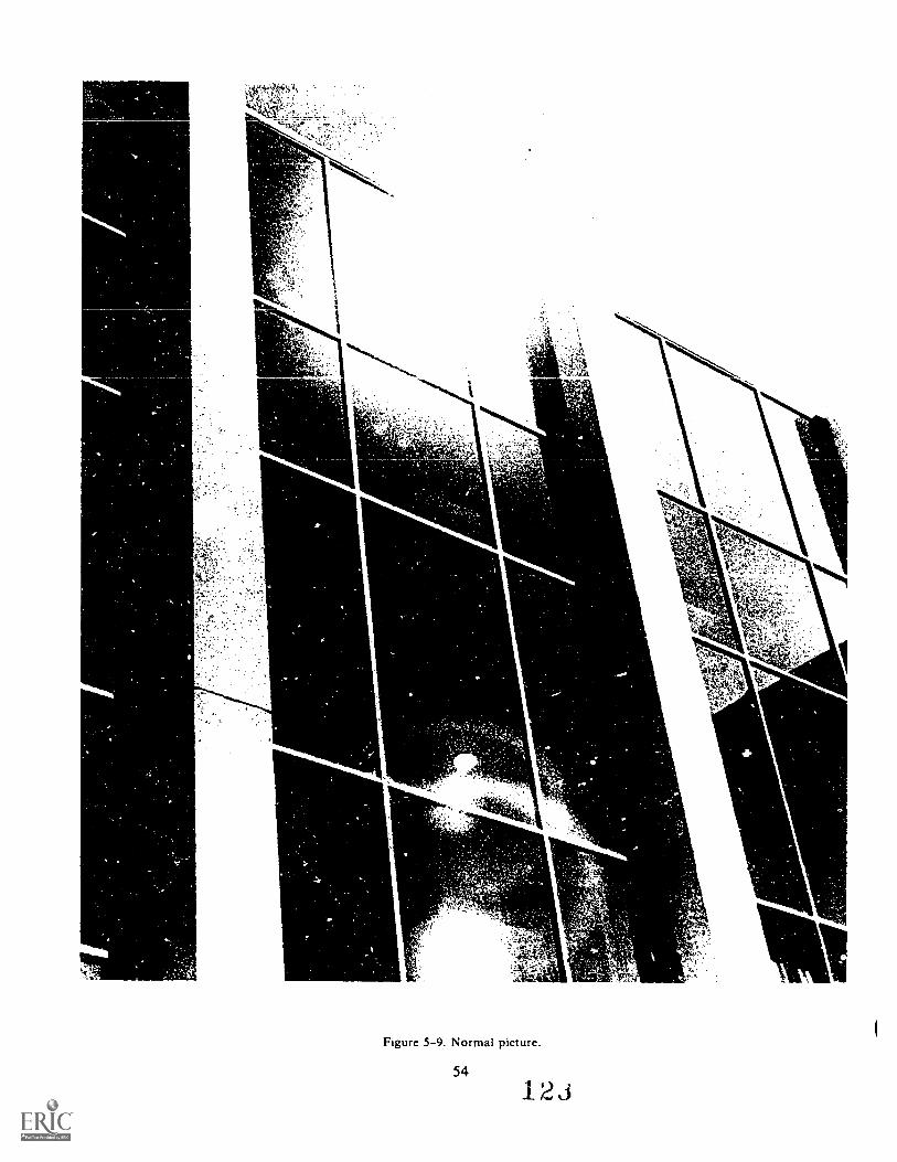
Figure 5-9. Normal picture.
54
1 2 J
1
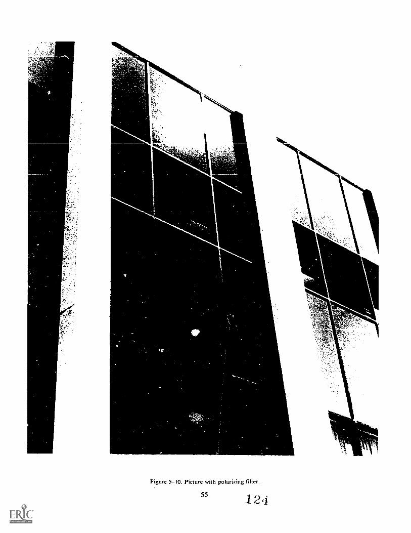
I
MI
Figure 5-10. Picture with polarizing filter.
55 124
consequently the maximum darkening of the sky canbe achieved without darkening the tone or colors in therest of the shot. If the camera is pointed towards thesun or 180° from it, there is no such effect. A polarizingfilter has a factor of about 2.5. If used with anotherfilter you should ms44.154 the filter factors together toget a new one to work with. When not used forpolarizing, the filter acts as a neutral density filter.Exercises (249):
1 What is polarized light?
2. What does a polarizing filter do to polarized liehtand to nonpolarized light?
3. A polarizing filter is used on what kind of subjects?
5-8. Haze PenetrationsHaze is a problem in all outdoor daylight
photography. Haze causes an overall bluish cast incolor photographs, and lowers contrast in both black-and-white and color photos. This is because moistureand particles in the air scatter light as it passes throughthe atmosphere. The blue portion of the spectrum isaffected most. Haze is a problem in scenic and aerialphotography (particularly important to the Air Force).Filters and certain filter/film combinations are helpfulin fighting this basic photographic problem.
250. Explain how certain filter/film combinations can.penetrate haze.
Black-and-White Panchromatic Film. Due to theexcess blue found in hazy conditions, a yellow, orange,or red filter coupled with panchromatic film is bestsuited for the job. The choice of filter depends on howbad the haze is. The darker the filter the more hazepenetration, but a darker filter requires increasedexposure. For example, a red filter gives good hazepenetration but has a filter factor of about 8. Amedium yellow or orange may prove the best forgeneral outdoor scenics. A red might prove best foraerial work.
Black-and-White Infrared Film. Infrared filmprovides better hare penetration than panchromaticfilm because it can record the hare penetrating infraredrays that are longer than visible red. A dark red filter(Wratten 29 or 70) should be used to absorb theultraviolet and blue rays of light. Exposure should bewell bracketed to insure adequate density sinceordinary exposure readings will not work.
Color Film. There are three basic filters that canreduce haze in color films: Skylight, UV, and Haze. ASkylight filter (light pink in color) absorbs ultravioletand some excess blue. A UV filter (yellowish tint) alsoabsorbs ultraviolet and excess blue, but may add aslight overall yellowish cast to the picture. A Haze filteris practically clear and absorbs some of the ultravioletrays without making much of a color shift.
NOTE: These three filters require no change inexposure because of their very pale nature. They alsomay be used with black-and-white films. Aphotographer often leaves one of these filters in placeover the lens at all times for protection of the lens andabsorption of ultraviolet light.
Color Infrared. Color infrared has good hazepenetrating characteristics and is increasingly used inreconnaissance photography. The film can also be usedfor striking pictorial effects. When using color infraredit is recommended that you use a deep yellow filter.When this is done green foliage comes out magenta,but clouds are white and the sky is blue. Other filterscan be used but the colors are very distorted (i.e. with ared filter the sky is rendered green, clouds are yellowand foliage is orange).
NOTE: This is the only color film where filtersdesigned for black-and-white photography arerecommended.
Exercises (250):
1. Why is the use of panchromatic film with a red filtera good haze cutting combination?
2. What is the advantage of using infrared film to cutthrough haze?
3. Why is a red filter used with black-and-whiteinfrared film?
56 12o
Bibliography
Books
Carroll, John S. Photographic Lab Handbook. New York: Amphoto, 1970.
Stroebel, Leslie and Todd, Hollis N. Dictionary of Contemporary Photography.New York: Morgan and Morgan, 1977.
Swedlund, Charles, Photography. New York: Holt, Rinehart and Winston. Inc.,1971.
NOTE: None of the items listed in the bibliography above are available through EC1. If you cannot borrowthem from local sources, such as your base library or local library, you may request one item at a time on aloan basis from the AU Library, Maxwell AFB, AL 36112, ATTN: ECI Bibliographic Assistant. However,the AU Library generall) ids only books and a limited number of A Fills. TOs, classified publications, andother types of publications are not available. Refer to current indexes for the latest revisions of and changesto the official publications listed in the bibliography.
12u57
CHAPTER 1
Reference:
ANSWERS FOR EXERCISES
200 - I. I. Light.2. It is reflected.3. Transparent.4. It is absorbed.5. Refracted.6. Reflection; absorption.
201 - I. a. Direct sunlight diffused through the earth'satmosphere.
b. Light reflected from the sky.c. Light reflected from objects on the earth's surface.
201 - 2. a. Geographic location.b. Time of day.c. Season of the year.d. Weather conditions.
201 - 3. a. Flat lighting - subject faces the sun.b. Backlighting - camera faces the sun.c. Open shade subject in a shaded area, with the sky as
background.
202 - L I. Lower output and color quality.2. Yes. Don't overload circuits. Don't splash water on
them. Keep them away from combustible materials.3. Natural.4. From the main lamp.
203 - I. a. Portability.b. Extr4inely short flash duration.
203 - 2. a. Minimizes the adverse effects of camera and subjectmovement.
b. Eliminates need for hot lights, used in portiait making.203 - 3. Yes. It fills in shadows, stimulates sunlight under hazy
skies, and approximates natural sunlight conditions.
204 - 1. c, d, e, f, h.
205 - I. a. Phosphor. It converts ultraviolet light to visible light.b. Longer than 1/60 second. Florescent lights pulse 4O GO
times every second.c. Green. When using color film.
21() - I.
211 - I.
used, shadow detail will be lost or highlights blocked up asail attempt is made to expose for this range of highlightsand sh ad ow s.
a.b.c.
a.b.c.d.
f, 22.I/ 5.6.fi 5.6.
f/ 16.10 feet.10 feet.f/8.
212 - 1. a. True.b. False. Incident light meters do not consider the tone
value of the subject at all.e. False. Point the light-gathering receptor toward the
camera.d. True.e. True.f. False. A flash meter can compute exposure for more
than one flash unit or bounce flash.g. True.
213 - I.
213 - 2.
213 - 3.
213 4.
214 - I.
CHAPTER 2
206 - I. The formula for photographic exposure is E = I X T.206 - 2. The two factors that determine exposure are the intensity
of the exposing light and the amount of time It is allowedto strike the film.
207 - I. a. 1/250 at f/4.b. 1/60 at f/ 11.c. 1/ 250 at f/ 4.
208 - I. The law of reciprocity is expressed in the formula, E = I XT. This formula means that if the product of the lightintensity and the time of the light action is the same foreach exposure, then each sheet of film having the samefilm speed will have the same density when processed thesame.
208 - 2. When you have conditions of extremely high or lowintensitieis, normally marked by extremely short or longexposure times, you will have reciprocity failure.
208 - 3. Reciprocity failure results in a loss of film speed whichcauses underexposed negatives.
209 - I. The scene brightness range is the difference between ascene's highlights and its shadows.
209 - 2. The scene brightness range sets the contrast of the scene. Ifthe contrast is beyond the limits of the film that is being
59
215 - I.
Cover the photoelectric cell opening. (With some metersyou must remove the batteries.)Yes. High intensities may cause the indicator needle tobounce at the high end of the scale and eventually causedamage to the unit.Keep it in the carrying case and away from heat (125° F51.7° C).Pointing it at the sun.
a. True.b. False. Change "an incident" to "a reflected."c. True.d. False. Change "at a 45' angle to the subject" to
"perpendicular to the ground."
a.b.c.d.e.
216 - I. a.b.c.
CHAPTER 3
Overcoating.Emulsion.Two.Film base.Culring; halation.
Film; processing.Middle tones.Slow; even.
217 - I. All silver halides are sensitive to ultraviolet, violet, andblue.
217 - 2. Optical sensitization is the method used to increase thesensitivity of an emulsion by dyeing or staining the silverhalide crystals.
217 - 3. Panchromatic film.
218 - I. The ability of an emulsion to record a range of subjectbrightnesses is called film latitude.
218 - 2. Exposure latitude is directly related to the film's inherentlatitude. If the film has wide inherent latitude, it will alsohave wide exposure latitude.
218 - 3. Latitude in black-and-white film is related to film speed.
219 - I. American National Standards Institute (ANSI).219 - 2. a. Exposure.
b. 200.c. Density.d. Slowest.e. Slow.
12(
220 - I. Contrast is the difference between high and low densitiesof a negative,
220 - 2. A normal contrast negative will have a full range ofdensities, including highlights, middle tones, andshadows.
220 - 3. Slow speed films usuaily have the highest in crentcontrast.
220 - 4. Generally, the more development, the more the contrast.221 - I. a. Many.
b. Exposure.c. Speed; high.
222 - I. Since orthochromatic film is not sensitive to red and issensitive to only blue and green it is limited to subjects thatdo rot have a full range of colors.
223 - 1. c; d; f.
224 - I. I. c.2. h.3. c.4. d.5. f.6. a.
225 - I.225 - 2.225 - 3.225 - 4.
Red.Haze.Increased.Heavy.
CHAPTER 4
226 - I. Focal length is the distance from the optical center of thelens to the image produced at the focal plane when the lensis focused on infinity (a condition that exists when lightrays from distant objects enter the lens in a nearly parallelattitude).
227 - 1. In the formula, f FL if s f / stop; FL is focal length; and Dis diameter.
227 - 2. A fast lens has a wide maximum aperture.227 - 3. A slow lens has a small maximum aperture.227 - 4. An f/ 4, 100mm lens is slower than an f/ 2, 100mm lens
because the 1/ 4 lens has a smaller maximum aperture.
228 - 1. The circle of illumination is the total light proejcted by alens.
228 - 2. The usable circle of illumination is that part of the circle ofillumination that is bright enough to produce usableimages.
229 - I. The angle of field of a lens is the widest angle at which lightenters the lens and produces the usable portion of thecircle of illumination. The angle of view is the angle of lightthat is necessary to provide adequate coverage of the filmthat is being used. It may be equal to but is never greaterthan the angle of field.
230 - I. Resolution refers to the ability of a photographic lens ormaterial to record fine detail. The normal method ofmeasuring this quality is to photograph a suitable testpattern at a greatly reduced scale, and then examine thedeveloped image under adequate magnification tocalculate the smallest detail.
230 - 2. Definition refers to the quality aspect of a photograph thatis associated with the clarity of detail. It is a subjectiveevaluation based on an observer's view of the photograph.
231 - I. The purpose of coating a lens is to improve lighttransinission and reduce optical flare.
231 - 2. The lens should be cleaned with the proper tools. Theseinclude: a fine brush, lens tissue, and lens cleaningsolution. Throughout the process of dusting, cleaning, andpolishing there should be no undue pressure that would"rub-off' the lens coating.
60
232 - I. A normal lens has a focal length that is about equal to thediagonal dirnension of the film being used.
233 - I. a. Shorter.b, Smaller.c. Depth of field,d. Center; edges.
234 - L A long focal length lens has a focal length greater than thediagonal dimension of the film.
234 - 2. The narrower angle of coverage and the larger image sizefor a given subject-to-camera distance produced by a long-focal-length lens isolates the subject from itssurroundings. A short-focal-length lens has much widercoverage and, thus, a problem of creating a strong point ofinterest.
234 - 3. Long-focal-length lenses magnify camera shake, and it isnecessary to use high shutter speeds to correct thisproblem.
235 - I. a.b.c.d.e.
True.frue.False.True.False.
236 - 1. You can change focal lengths without changing lenseswhen you use a zoom lens.
236 - 2. One disadvantage of a zoom lens is that they do notproduce extremely sharp images.
237 - 1. The two controis that determine image size are: (1) thefocal length of the lens that is used and (2) the lens-to-subject distance. The longer the focal length, the larger theimage size. The closer the lens-to-subject distance, thelarger the image size.
238 - I. Perspective is the impression of depth when a 3-dimensional scene is represented in a 2-dimensionalphotograph.
238 - 2. Focal length does not change perspective. It changes yourperception. Changing focal length changes the relative sizeof your subjects, but they are still in the same relationshipto each other.
239 - I. Depth of field is the zonc extending in front of and behindthe point in sharpest focus.
239 - 2. 1. Focal length. Short focal length lenses have greaterdepth of field.
2. Lens to subject distance, the farther away an object isfrom the lens, the greater the depth of field.
3. Aperture. A small f/ stop will increase the depth offield.
239 - 3. Focus 2 feet into a 5-foot subject to insure adequate depthof field.
239 - 4. Hyperfocal distance is the distance from the lens to thenearest phone that is in acceptable focus when the lens isfocused on infinity. Each f/stop has a different hyperfocaldistance.
240 - 1. Depth of focus is the zone or area within which the filmcan be moved and still be in focus.
241 - 1 Critical apei ture is the ap ature of a lens that produces thesharpest image. It is usual), two f /stops from wide open.
242 - I. Mechanical flare is caused by reflections that occur off thelens barrel or camera. These reflections are usually causedbecause a metal surface has been damaged or burnished.The method of correction is to coat these surfaces with anonreflective coating.
242 - 2. Optical flare is caused by reflections off the glass surfacesof the lens. Such flare can be reduced or eliminated by aproper lens coating and the use of a lens shade.
126
CHAPTER 5
243 - I. The two advantages in using gelatin filters arc that they arcinexpensive and come in a wide variety of colors.
24;4 - 2. Glass filters are quite durable as compared with gelatinfilters.
243 - 3. All filters fade in time and have to be replaced.
244 - 1. a. A blue filter transmits blue and absorbs green and redlight.
b. A combination of a green and yellow filter wouldtransmit green and absorb red and blue.
c. The complementary combination of red and cyanwould abosrb all colors of light.
d. Magenta would pass red and blue and absorb greenlight.
244 - 2. Red, green, and yellow filters should not be used with bluesensitive film, since it is sensitive only to blue andultraviolet light. Any filter that would completely absorbblue would be unsuitable.
244 - 3. The thickness of the filter can cause focusing problems.The thicker the filter, the greater the alteration to the lightwaves. It is therefore best to focus with the filter in place.
245 - I. a. I / 125.b. f/ 16.c. ASA 40.
246 - I.
247 - I. a. The rose appears light and the green leaves appearquite dark.
b. Using a green filter gives the sky a more natural toneand produces more detail in the grassy meadow.
61
c. The orange filter causes the sky to appear quite darkand the White House to stand out to a greater der, ce-
d. The blue filter causes the sky to appear quite light andhazy with little detail. This can give quite a feeling ofdepth.
248 - I. The purpose of a neutral density filter is to cut down theintensity of the light striking the film without changing itscolor quality.
248 - 2. By using a neutral density filter you can preventoverexposure when you arc using a high-speed film in ahigh-intensity lighting situation, and you may be able toselect latge aperture settings or slow shutter speeds forcompositional reasons and yet not be overexposure.
249 I. Polarized light is light that is vibrating in only onedirection.
249 - 2. A polarizing filter blocks polarized light that isperpendicular to it. The filter polarizes nonpolarized light.
249 - 3. A polarizing filter is used to cut down reflections fromnonmetallic surfaces and to darken blue skies.
250 - I. In a hazy situation you have an excess of blue. A red filterabsorbs blue to a greater degree than other filters, andtherefore permits a greater percentage of haze cutting redwavelengths of light from the image on the film.
250 - 2. Infrared film is sensitive to infrared waves that arc longerthan red. The longer wavelengths of light are better able tocut through haze. This results in greater detail.
250 - 3. A red filter is used with infrared film to absorb blue andultraviolet wavelenths. This insures that the image will beformed by red and infrared wavelengths.
1 2 AU GAFS.AL. (791441 )3000
S T 0 P - 1. MATCH ANSWER SHEET TO THIS EXERCISE NUMBER.2. USE NUMBER 2 PENCIL ONLY.
EXTENSION COURSE INSTITUTEVOLUME REVIEW EXERCISE
23132 02 22STILL PHOTOGRAPHIC FUNDAMENTALS
Carefully read the following:DO's:1. Cheek the "course," "volume," and "form" numbers from the answer
sheet address tab against the "VRE answer sheet identificationnumber" in the righthand column of the shipping list. If numbers donot match, return the answer sheet and the shipping list to ECIimmediately with a note of explanation.
2. Note that item numbers on answer sheet are sequential in each
column.3. Use a medium sharp #2 black lead pencil for marking answer sheet.4. Write the correct answer in the margin at the left of the item.
(When you review for the course examination, you can cover youranswers with a strip of paper and then check your review answersagainst your original choices.) After you are sure of your answers,transfer them to the answer sheet. If you have to change an answeron the answer sheet, be sure that.the erasure is complete. Use a
clean eraser. But try to avoid any erasure on the answer sheet ifat all possible.
5. Take action to return entire answer sheet to ECI.6. Keep Volume Review Exer ise booklet for review and reference.7. If mandatorily enrolled student, process questions or comments
through your unit trainer or OJT supervisor. If voluntarilyenrolled student, send questions or comments to ECI on ECI Form 17.
DON'Ts:1. Don't use answer sheets other than one furnished specifically for
each review exercise.2. Don't mark on the answer sheet except to fill in marking blocks.
Double marks or excessive markings which overflow marking blockswill register as errors.
3. Don't fold, spindle, staple, tape, or mutilate the answer sheet.4. Don't use ink or any marking other than a #2 black lead pencil.NOTE: NUMBERED LEARNING OBJECTIVE REFERENCES ARE USED ON THE VOLUME
REVIEW EXERCISE. In parenthesis after each item number on theVRE is the Learning Objective Number where the answer to thatitem can be located. When answering the items on the VRE, referto the Learning Objectives indicated by these Numbers. The VREresults will be sent to you on a postcard which will list theactual VRE items you missed. Go to the VRE booklet and locatethe Learning Objective Numbers for the items missed. Go to thetext and carefully review the areas covered by these references.Review the entire VRE again before you take the closed-bookCourse Examination.
1
1,3 ti
23132 02 22

Multiple Choice
1. (200) Light rays that are bent as they pass through a mediumare
a. absorbed. c. dispersed.b. refracted. d. reflected.
2. (200) When light strikes a surface, all of the following canoccur except
a. transmission.b. absorption.
0. conversion.d. reflection.
3. (201) What is your major problem with using open shade illumination?
a. Eye squinting.b. Exposure computation.c. Light diffusion.d. Cluttered background.
4 (202) Regular household lamps are not generally used for photographybecause they have insufficient
a. heat.b. color.
c. infrared rays.d. output.
5. (202) When you are using more than one lamp to light your subject,the lamp pointed at the back of the subject provides
a. hair light. c. main light.b. fill light. d. halo light.
6. (203) Which one of the following is not an advantage of electronicflash?
a. The weight is less.b. Electrocio flashes provide more light.0. Exposures need not be computed.d. Short duration can stop action.
7 (204) Which one of the following characteristics are associatedwith quart ipIine lamps?
a. Constant color quality.b. Ability to stop action.c. Cool burning.d. Can be handled with bare hands.
2
13t
23132 02 22
8. (205) When you are using fluorescent lights yaw shutter speedshould be
a. calculated at the subject.b. longer than 1/60 second.c. disregarded since fluorescent lights pulse.d. determined with a green filter over the light meter aperture.
9. (206) In the exposure formula, E = I X T, if E equals exposure,what does I and T equal?
a. Illumination and time.b. Interval and time.c. Intensity and time.d. Intensity and temperature.
10. (206) One unit of light falling on a piece of film for ten secordsis the same as 2 units of light falling on the film for
a. 2 seconds. c. 5 seconds.b. 3 seconds. d. 7 seconds.
11. (207) In the exposure formula, E = I X T, which cam-ra controldetermines I?
a. Lens.b. Shutter.
c. Diaphragm.d. Bellows.
12. (207) Additional light will strike the film in a camera whenthe
a. f/stop is moved down.b. f/stop is moved substantially upward.c. diaphragm is "closed down a stop."d. Shutter speed is increased.
13. (207) Refer to figure 2-2. Which one of the following exposurecombinations is the same as f/8 at 1/100?
a. f/5.6 at 1/50.b. f/11 at 1/250.
c. f/16 at 1/25.d. f/22 at 1/2.
14. (208) What is the effect of reciprocity failure?
a. Negatives will be overexposed.b. Inherent grain will increase.c. A gain in negative density.d. An apparent loss of film speed.
133
23132 02 22
15. (208) When will reciprocity failure most likely happen?
a. At extremely long or short exposures times.b. After the film has been stored in a freezer.c. Under extra bright lighting conditions.d. During the early morning hours of the day.
16. (209) The relative difference between the brightest and darke:-Itareas of a subject is called
a. shadow ratio differences.b. scene brightness range.c. brightness ratio range.d. highlight contrast factor.
17. (209) What lighting ratio can most films handle before you geta washed out highlight?
a. 1:100.b. 1:128.
c. 1:200.d. 1:260.
18. (210) What two factors are used to calculate exposures?
a. Film speed and development time.b. Film speed and subject brightness.c. Lens diaphragm and lens speed.d. Subject brightness and diaphragm size.
19. (210) When using an exposure guide chart and a film with a filmspeed of 125, what shutter speed should you use?
a. 1/25.O. 1/50.
C. 1/125.d. 1/250.
20. (211) Exposure for flash photography is based on what two factors?
a. Output of flash and subject speed.b. Guide number and f/stop.c. Film speed and shutter speed.d. Output of flash and distance to subject.
21. (211) If the guide number for your electronic flash is 160 andthe flash is 10 feet from the subject, what is the proper f/stop?
a. 16.b. 22.
c. 32.d. 45.
13i
23132 02 22
22. (212) Incident light meters measure the light that
a. is reflected from the subject.b. the neutral gray card reflects.c. cannot be measured at the camera position.d. falls on the subject.
23. (212) When you use an incident light meter you should point thr,receptor toward the
a. camera.b. subject.
c. sun.d. gray card.
24. (212) Which one of the following is not a method of taking reflectedlight readings?
a. Average. c. Substitute.b. Brightness range. d. Spotting.
25. (212) If you cannot approach your subject to take a light reading,which one of the following methods should you use?
a. Average. c. Substitute.b. Brigtness range. d. Spotting.
26. (213) When you operate an exposure meter you should not
a. clean the glass over the cell.b. point the cell toward the sun.c. cover the cell to zero the meter.d. check for sticky needle movement.
27. (214) What percentage of the incident light does the gray sideof a neutral density gray card reflect?
a. 10 percent.b. 18 percent.
c. 50 percent.d. 90 percent.
28. (214) One way of compensating for readings taken from the whiteside of neutral-test card is to divide the ASA of the film by
a. 90.
b. 18.
5
c. 10.
d. 5.
23132 02 22

29. (?15) What is the purpose of the film's overcoating?
a. Protect the emulsion during handling.b. Hold the silver crystals in place.c. Bond the emulsion to the base.d. Prevent halos around the bright objects.
30. (216) What causes gr=lin in a negative?
a. Clumping of silver halides.b. Lengthy storage periods.c. Failure of the overcoating.d. Long exposure times when printing.
31. (;117) In a normally prepared emulsion, the silversen:Ative to all of the following except
a. ultraviolet. c. infrared.b. violet. d. blue.
r-clides a re
32. (P18) What is it that allows you to use several possible exposuresand still get acceptable negatives?
a. Scene brightness range.b. Exposure latitude.c. Inherent grain.d. Narrow film speed.
33. (219) If you were using a film with an ASA of 100 and your exposurewas f/8 at 1/50, what is your exposure if you change to a filmwith ASA 200?
a. 178 at 1/100. c. f/11 at 1/250.b. f/11 at 1/125. d. f/16 at 1/200.
34. (219) For which one of the following situations should you usea high-speed film?
a. An outdoor portrait.b. A brightly lit snow scene.c. Copy work of a white subject.d. Indoors where a flash cannot he used.
6
1 3
23132 02 22

35. (220) Which one of the following has no bearing on the contrastof a negative?
a. Shutter speed. c. Film development.b. Subject lighting. d. Inherent contrast.
36. (2P0) What type of film emulsion usually has the highet inherentcontrast?
a. High speed. c. Daylight.b. Low speed. d. Tungsten.
37. (221) Which of the following charateristics are generally associatedwi.th high-resolution films?
a. Slow speed and high contrast.b. Slow speed and low contrast.c. High speed and high contrastd. High speed and low contrast.
38. (222) An orthochromatic film is least sensitive to
a. blue color.b. green color.
c. violet color.d. red color.
39. (223) What type of emulsions most closely match the sensitivityof the human eye?
a. Color blind. c. Panchromatic.b. Orthochromatic. d. Infrared.
40. (224) The positive image in the Polaroid materials is producedby a process known as
a. conversion viscosity. c. positive development.b. diffusion transfer. d. displacement monobath.
41. (225) In order for infrared film to properly record the scene,what filter must you use over the lens?
a. Deep green. c. Deep red.b. Light yellow. d. Light blue.
7
136
23132 02 22

42. (226) The distance from the optical center of f.11
fecal plane when the lens is fccused on infinit
a. hyperfocal distance. C. conjugate 61sLanee.b. focal point. d. focal length.
to thecd Lhe
(P?7) Which ono of the following is the formula for deter:niningthe speed of a lens?
a. f = FL/D. c. S = f/D.b. f = D/FL. d. S = D/f.
(;T8) The circle of illumination
a. all of the light projected by a lens.b. controlled by the photographer.c. used only on view cameras.d. brighter at the edges than in the center.
45. (229) The maximum coverage of a lens is expressed in degreesas being the
a. focal length.b. angle of field.
c. optical coverage.d. angle of acceptance.
46. (230) The capability of a lens to record fine detail is called
a. accuteness. c. granularity.b. abberation. d. resolution.
47. (231) The purpose for coating a lens is to
a. keep it from being tarnished.b. minimize internal reflections.e. make the lens slower.d. help reduce surface scratches.
48. (232) The focal length of a "normal" lens is equal to the
a. diagonal dimension of the film.b. length times the width of the film.c. circle of illumination divided by the speed of the lens.d. circumference of the lens times the aperture.
8
13(
23132 02 22
49. (233) Whi,A1 one of the following is not a elmractertic or awide angle lens?
a. Short focal length. c. Usable in cramped arca.b. Good depth cf field. d. Large image size.
50. (4) A long-focal-length lens will
a. produce a small image size.b. increase the depth of field.c. produce a large image size.d. change the center of perspective.
51. (234) Which one of the following statements is true regardinglong focal length lenses?
a. The focal length of a long foeal length lens is usally shorterthan the diagonal dimension of the film.
b. You must use slow shutter speeds with a long focal lengthlens.
c. The depth of field is greater with a long focal length lens.d. The size and weight of the long focal length lens will sometimes
require a tripod.
52. (235) Which one of the following statements is true regardingtelephoto lenses?
a. They are designed the same way as long-focal-length lenses.b. You must use a slow shutter speed when using telephoto lenses.c. A negative rear element is used to achieve the long effective
focal length.d. You cannot use a telephoto lenses on small format cameras.
53. (236) What type of lens allows you to change focal length withcmtchanging lenses?
a. Zoom. c. Wide angle.b. Telephoto. d. Fisheye.
54 (237) If you needed to produce a larger image size on your filmand you could not move the camera, you should use
a. a wide angle lens.b. a telephoto lens.c. the lens that is "normal."d. the 1800 fisheye lens.
9
13d
23132 02 22
55. (238) The impression of depth in a 2-dimensional picture is knownas
a. distinction. c. perspeetive.b. depth of field. d. relationship.
56. (239) If you must increase the depth of field, what action shou]dyou take?
a. Use a long focal length lens.b. Move closer to the subject.c. Close down to a smaller aperture.d. Use the cpitical aperture.
57. (;-99) The distance from the lens to the nearest plane in focusis called the
a. acceptable focus length.b. hyperfocal distance.c. critical focal point.d. depth of focus.
58. (239) You need to take a picture of five objects in a straightline that runs generally away from you, what object should youfocus on to ensure adequate depth of field?
a. Any of the objects. c. The second object.b. The first object. d. The last object.
59. (240) The zone or area that the field can be moved back and forthin without being unacceptably sharp is called the
a. depth of field. c. 2/5th zono.b. focal length. d. depth of focus.
60. (241) How many f/stops is the critical aperture from the widestaperture?
a. Two.b. Four.
c. Five.d. Eight.
61. (242) Optical flare and mechanical flare are caused by
a. the coating on the lens.b. being too close to your subject.c. simple one-element lenses.d. reflections in or near the lens.
10
13J
23132 02 22
62. (243) Which one of the following types of filter:; vilablein the widest variety of colors?
a. Glass. c.
b. Gelatin. d. :iffen.
63. (243) Which type of filter is the most durable?
a. Plastic. c. Tiffen.b. Glass. d. Gelatin.
64. (244) If you used orthochromatic film with a red filter, whateffect would this Ave on the negative?
a. Red objects would be dark and green objects would be light.b. Blue, green, and red objects would compintely expose the negativec. Blue objects would be light and red objects would be dark.d. Red, green, and blue objects would not make an exposure.
65. (244) Which of the following combinations could you use in placeof a red filter?
a. Yellow and cyan. c. Yellow and magenta.b. Magenta and green. d. Blue and magenta.
66. (245) If you had a basic exposure of f/8 at 1/100 and were usinga filter with a factor of 2, what is your new shutter speed?
a. 1/200.b. 1/150.
c.
d.
1/50.1/25.
67. (245) When you use a filter with a filter factor of 4 and yourbasic exposure was f/16 at 1/100, what is your new exposure?
a. f/8 at 1/250. c. f/16 at 1/200.b. f/8 at 1/50. d. f/16 at 1/25.
68. (246) Orthochromatic film cannot be used to achieve orthochromaticrendition t,,:cause the film is
a. too slow.b. limited in sensitivity.c. too high in contrast.d. too low in contrast.
11
23132 02 22
69. 246) What color of correction filter can you use to achieveorthochromatic rendition of an outdoor scene when you are usingpanchromatic film?
a. Medium yellow.h. Light blue.
c. Orange.d. Red.
70. (247) If you want a red flower to appear darker than the greenleaves in the final print, what color of contrast filter shouldyou use with panchromatic film?
a. Green.h. Red.
c. Blue.d. Yellow.
71. (247) A red filter would help produce acceptable results forall of the following except
a. fake night shots.b. portraits of women.c. scenics where you want to darken the sky.d. architecture shots of light-tone buildings.
72. (248) If the light is so bright that you cannot close down enoughor use a fast enough shutter to prevent over-exposure, what kindof filter should you use?
a. Neutral density. c. Correction.b. Polarizing. d. Light balancing.
73. (P48) If you needed to close down one stop and couldn't becauseof the limitations of your lens, you should choose n neutral densityNlter with a factor of
a. 2.
b. 4.0. 7.7.d. 20.
74 (249) What type of filter can you use to reduce glare from water,windows, and glossy prints?
a. Polarizing. c. Contrast.b. Correction. d. Gelatin.
7. (250) What color of light is in excess in a hazy lighting condition?
a. Red.b. Orange.
12
c. Yellow.d. Blue.
141
23132 02 22
MAIL TO: EC1, GUNTER AFS AL 3611 ti.b643
STUDENT REQUEST FOR ASSISTANIPRIVACY ACT STA ILMLNTAL I liuRli Y, 10 LISC 801.1. PRINCIPAL PI RPOSE: Tu provide student assistance as requested ht, indisidnal stuticnt, 11(11 I I .1 1,1, I ormshippcd with t-.C1 Course Backup-. and Used hy the Mndent, as needed, Is plate in ifinlOry mini I- (.1. DISC) \ he .70..1,, ;,.0.-.1,11hits turn. is needed for esprditions handling of the student's inquiry, Failure to ;mistily all intannia T i )))) mould reoill sl,v. cr ,1 1110..111, I,. at,rassistance to the student.
I. 11115 fit:QUEST CONCERNSCOURSE (I-6)
CORRECTED OR LATEST ENROLLMENT DATA2. TODAYS DATE
SOCIAL SECURITY NUMBER (7.16)
I 18 ADDRESS
0.11 C.N1W1.1.1-.1.:5 Address of snit training eewith zip Code,
.11.1-17/7/E11.1-Current address with rip code.
6 GRADE/RANK
(33-53)
(74-751
NAME OE BASE OR INSTALLATION IF NOT SHOWN ABOVE
3. ENROLEMEN 1 ETA TI IT
7. NAME Wiry/ 544.1511.1,.(1./1.
IS. TEST CONTROL OFFICE ZIP COOE/sHISED- I33 .1;,1
2
3
4
5
6
REQUEST FOR MATERIALS, RECORDS, OR SERVICEPlace an:X. Ihr.nigh number in box wrviee requesied.
Retpiest address change as indicated in Section I, Block 8.
Remiest Test Control Office change as indicated in Section I. Block 10.
Request twine change/correction.(Prot./dr Old or /new-reel dava here)
Request Grade/Rank change/correction.
Correct SSAN. (1. isr incorre, I SSA N here.)i( orre. SS.I .V should be shown in Seelion I.)
Ustend course completion date. (Jus(iie in "Remarks-)
FOR 1-1(71 USE ONLY
Request enrollment cancellation. (Juslify in "Remarks-)
8 send \Au: answer sheets for Vol(s): 1 2 3 4 5 6 7 8Aniginals were: I I Not received I Lost I MisusedSend conrse materials. (Sp, eily in "Remarks")
Not received [ I I ost ( Damaged9
10
12
13
14
(,ont esalll nut yet iceeived. Final VR1 . submitted for grading oii
11 I 0
Re-adts for VRE Vol(s) 1 2 3 4 5 6 7 8 9 10 not yet received.Answer sheet(s) submitted .(date).
(date
6
vOL 33 35
33,34 15 41.
33- 55
Resolts for CE nut yet received. Answer sheet submitted to EC1 cm_ __Adam).
l'ies,,ms inquiry (I I EC1 I'm 17. I kr. [ J insg) sent to EC1 otr_. tdatet.
t:ive mstructional assistance OS requested On reverse.
()diet (l.;xplarn fully in "Remarks")
VOI- 33-35
TC 36-37
DOE 39-45
33-34 1-38
J41.Y 1
MC 39-42
RE64/1111Tas f('witIrltecoal reverse)
OJT STI OEN 15 must (wee their 0J1 Administrator certify ;his record.
(1-1-11E1f STIrDENTs rosy certify their own requests.
I (Truly Mai the infurmalion this form is acenraleand that this request cannot he answered al [Inc qaii.m
SIGNATURE
ECI FORM 17DEC 84 PREVIOUS EDITION WILL BE USED.
1 4 ,) BEST COPY AVAILABLE
REQUEST FOR INSTRUCTOR ASSISTANCENOTU: Stions or coll1Mellts felatitig to the accuracy or currency of subject matter should-lw forwarded- directly to prepatim_.,agency. Foi an immediate response to these questions, call or write die course author directly. using Me AUT0VON %lumber oraddress in the preface of each volume. All other inquiries concerning the course should be forwarded to ECI.
MY QUESTION IS:VRE ITEM QUESTIONED:
COURSE NO
VOLUME NO
VRE FORM NO
VRE ITEM NO
ANSWER YOU CHOSE(Letter)
HAS VRE ANSWER SHEET BEENSUBMITTED FOR GRADING?
Li YES U NO
REFERENCE
(Textual reference for the answer I chosecon be found as shown below.)
IN VOLUME NO
ON PAGE NO
IN LI LEFT C.3 RIGHT COLUMN
LINES THROUGHREMARKS
ADDITIONAL FORMS 17 available from trainers. OrT and EducationOffices, and ECI. Course workbooks have a Form 17 printed on the last page.
ECI FORM 17. DEC 8 4 (Reverse)
143
23132 03 7904
CDC 23132
APPRENTICE STILL PHOTOGRAPHIC SPECIALIST
(AFSC 2332)
Volume 3
Photographic Camera Assignments
Extension Course InstituteAir Training Command
144
Prepared byMSgt Curtis Mayne
andMSgt Jay Perry
3430th Technical Training GroupUSAF School of Applied Aerospace Sciences (ATC)
Lowry AFB, Colorado 80230
Reviewed byElmore C. Hall, Education Specialist
Extension Course Institute (ATC/AU)Gunter AFS, Alabama 36118
PREPARED BY3430TH TECHNICAL TRAINING GROUP
USAF SCHOOL OF APPLIED AEROSPACE SCIENCES (ATC)LOWRY AIR FORCE BASE, COLORADO
EXTENSION COURSE INSTITUTE, GUNTER AIR FORCE STATION, ALABAMA
THIS PUBLICATION HAS BEEN REVIEWED AND APPROVED BY COMPETENT PERSONNEL OF THE PREPARING COMMANDIN ACCORDANCE WITH CURRENT DIRECTIVES ON DOCTRINE, POLICY, ESSENTIALITY, PROPRIETY, AND QUALITY.
145
Preface
THIS THIRD VOLUME of CDC 23132, Apprentice Still Photographic Specialist,emphasizes the application of general camera assignments. Since photography is anart rather than an operational career field, we don't have cut and dried rules for cameraassignments. Therefore, most of this volume deals with concepts and ideas that areabstract.
Chapter 1 explains photographic composition. Many shots are spoiled by poorcomposition or a total lack of it. In this chapter, we offer ideas and concepts of com-position which you may use. We discuss creative techniques as well as ba6c conceptsand corrective procedures. Chapter 2 deals with general assignments. In this chapterwe cc ver the planning of missions, industrial, and investigative assignments. We alsogive you a brief introduction to photojournalistic techniques. It is not our intent tolay down rigid rules on how to accomplish these assignments, but to point out certaintechniques that you may find useful. Chapter 3 covers the types of photos you will haveto produce in the studio. These include portraits, passports, identification, and specialassignment photographs. In Chapter 4 we discuss the fundamentals of copy and repro-duction photography. We cover types of originals, techniques, processing, and finish-ing of copy materials. As in Chapters 2 and 3, Chapter 4 also covers operator'smaintenance.
If you have questions on the accuracy or currency of the subject matter of this text,or recommendations for its improvement, send them to the 3430th TCHTG/ TTM ZS,Lowry AFB CO 80230. Questions requiring immediate resolution may be directed tothe course author, AUTOVON 926-4142, between 0700 and 1530 hours (MST),Monday thisough Friday. NOTE: Do not use the suggestion program to submit correc-tions for typographical or other errors.
If you have questions on course enrollment or administration, or on any of ECI'sinstructional aids (Your Key to Career Development, Behavioral Objective Exercises,Volume Review Exercise, and Course Examination), consult your education officer,training officer, or NCO, as appropriate. If this agent can't answer your questions,send them to ECI, Gunter AFS AL 36118, preferably on ECI Form 17, StudentRequest for Assistance.
This volume is valued at 12 hours (4 points).Material in this volume is technically accurate, adequate, and current as of January
1979.
Contents
Page
Preface iii
Chapter
Principles of Photographic Composition
General Assignments 21
3 Studio Assignments 55
4 Reproduction Photography 66
Bibliography 75
Answers for Exercises
14

CHAPTER 1
NOTE: In this volume, the subject matter is developed by a series of Learning Objectives. Each of thesecarries a 3-digit number and is in boldface type. Each sets a learning goal for you. The text that followsthe objectives gives you the information you need to reach that goal The exercises following the infor-mation give you a check on your achievement. When you complete them, see if your answers matchthose in the back of this volume. If your resporhe to an e7nercise is incorrect, review the objective andits text.
Principles of Photographic Composition
COMPOSITION IN photography is a process ofcombining or relating all of the elements of a sceneinto a particular position or relationship within thespace of a photograph. When all parts of the scene arecombined to form one harmonious whole, the resultis a photograph having good composition.
Learning the art of good composition is similar inmany respects to learning any other skill or profession.First, learn the rudiments, cortectly. Then ,throughmuch practice and attention, develop the talent to ahigh state of perfection. In the early stages of learningwe depend almost exclusively on what we can see andhear, imitating what has been done before.
Much can be learned about composition by studyingvarious works of art and collections of good photo-graphs. Each one offers an example of how to presenta subject in an effective and interesting manner. By thesimple process of attempting to duplicate some ofthese photographs, many of the basic elements ofcomposition can be learned.
1-1. Applying Basic ElementsYou should have an idea of what you want as a final
product before you move in to make the shot. All sub-ject elements should be properly arranged withconsideration given to the lighting and the appearanceof the various tones, textures, and shapes (fig. 1-1.)Many distracting elements can be eliminated byapplying the principles of good composition. It willbe very difficult, if not impossible, to correct mistakescaused by the wrong camera position or poor scenearrangement at a later point in the photographicprocess. You should do your cropping and composingbefore you trip the shutter.
400. Specify principles and techniques which are usedto achieve effective composition.
Although good composition is something that eachphotographer must learn to feel for himself, you can
consistently produce good quality photographs byusing basic .guidelines for composing your picture.
Point of Interest. Every photograph should haveone definite point of interest. If the viewer is distractedby a jumble of elements, the main subject of thephotograph will not stand out. (See fig. 1-2.) Thismakes it difficult to determine the purpose of thephotograph. The point of interest may be a singleobject or consist of several elements. The key is that allparts should be arranged so that the viewer's attentionis drawn directly to the subject. (See fig. 1-3 )
Simplicity. One sure way to emphasize your subjectis to simplify by minimizing the number of elementspresented in the picture. As we have said before, thecamera lens sees everything that exists in front of it.Therefore, adjust your camera angle and camera-to-subject distance until all but the essentials have beeneliminated from wr picture. As a start towardsimplification: (1) move closer to your subject, (2)choose a plain background, and (3) let the lightingemphasize your subject. Compare figures 1-4 and 1-5to see the improvement that simplicity can make.
Horizon Line. Most outdoor, and many indoor,photographs have a real or imaginary horizon linethe line where the sky seems to meet the earth or wherethe foreground or middle ground meets the back-ground. The proper placement of the horizon line willhelp you arrange the background, the foreground, andthe main subject areas of your picture. You should tryto keep the horizon line level. (See fig. 1-6.) Next, tryto remember never to place the horizon line in thedirect center of the photograph. If you do, you dividethe photograph into two equal parts and produce adull and uninteresting picture. (See fig. 1-7.) Try toposition the horizon line above or below the exactcenter of the photograph. A high horizon line givesthe appearance of depth and distance. (See fig. 1-8.) Alow horizon line creates an appearance of increasedheight. (See fig. 1-9.)
The Golden Mean. The Greek sculptors and thegreat painters and architects of the Middle Ages used
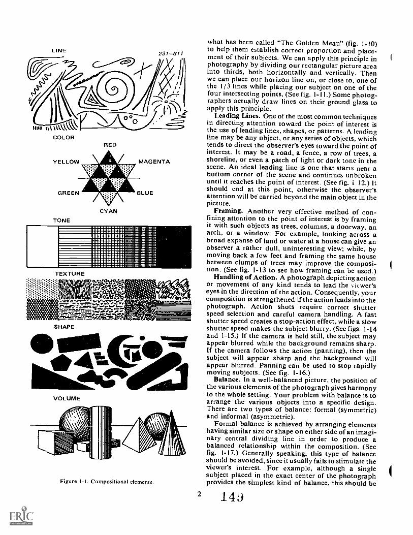
LINE
WM 1111 \ACOLOR
RED
CYAN
TONE
llllllllllllllll 1111111111
lllll 1 llllll 1111111111111 .
lllllll 111/111111111111111
l 111111 lllllll 1111111111111.11111 llllllll 1111111101111,1111 lllllll 110111111111111
llllllllll 11111/1111111011111 lllllll 1111111 lllll 1111
111111 lllllll 1111111111111111111 lllllll 11111111 lllllllll
TEXTURE
ii:::::: i Oealf-:.:-:;::::::::::: k % colesPe-oonle
Int:C6C1.1732Svi:\ oor TYZAPO.P:
-=- .,..,,,,,...--.....-:c ..........-414 ..aro atk M.
-411:44:r!V::SHAPE
VOLUME
MOO
dab..
Figure I-I. Compositional elements.
what has been called "The Golden Mean" (fig. 1-10)to help them establish correct proportion and place-ment of their subjects. We can apply this principle inphotography by dividing our rectangular picture areainto thirds, both horizontally and vertically. Thenwe can place our horizon line on, or close to, one ofthe 1/3 lines while placing our subject on one of thefour intersecting points. (See fig. 1-11.) Some photog-raphers actually draw lines on their ground glass toapply this principle.
Leading Lines. One of the most common techniquesin directing attention toward the point of interest isthe use of leading lines, shapes, or patterns. A leadingline may be any object, or any series of objects, whichtends to direct the observer's eyes toward the point ofinterest. It may be a road, a fence, a row of trees, ashoreline, or even a patch of light or dark tone in thescene. An ideal leading line is one that stans near abottom corner of the scene and continues unbrokenuntil it reaches the point of interest. (See fig. i !2.) Itshould end at this point, otherwise the observer'sattention will be carried beyond the main object in thepicture.
Framing. Another very effective method of con-fining attention to the point of interest is by framingit with such objects as trees, columns, a doorway, anarch, or a window. For example, looking across abroad expanse of land or water at a house can give anobserver a rather dull, uninteresting view; while, bymoving back a few feet and framing the same housebetween clumps of trees may improve the composi-tion. (See fig. 1-13 to see how framing can be used.)
Handling of Action. A photogeaph depicting actionor movement of any kind tends to lead the iewer'seyes in the direction of the action. Consequently, yourcomposition is strengthened if the action leads into thephotograph. Action shots require correct shutterspeed selection and careful camera handling. A fastshutter speed creates a stop-action effect, while a slowshutter speed makes the subject blurry. (See figs. 1-14and 1-15.) If the camera is held still, the subject mayappear blurred while the background remains sharp.If the camera follows the action (panning), then thesubject will appear sharp and the background willappear blurred. Panning can be used to stop rapidlymoving subjects. (See fig. 1-16.)
Balance. In a well-balanced picture, the position ofthe various elements of the photograph gives harmonyto the whole setting. Your problem with balance is toarrange the various objects into a specific design.There are two types of balance: formal (symmetric)and informal (asymmetric).
Formal balance is achieved by arranging elementshaving similar size or shape on either side ofan imagi-nary central dividing line in order to produce abalanced relationship within the composition. (Seefig. 1-17.) Generally speaking, this type of balanceshould be avoided, since it usually fails to stimulate theviewer's interest. For example, although a singlesubject placed in the exact center of the photographprovides the simplest kind of balance, this should be
2 14j
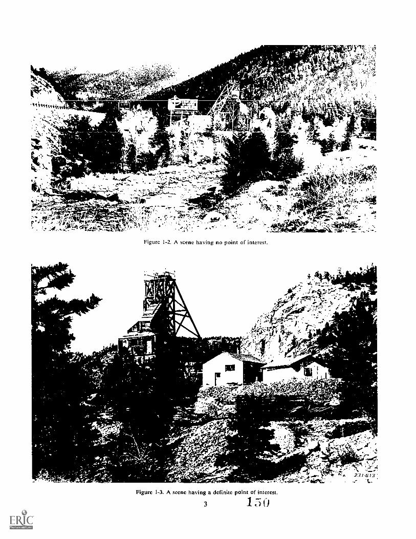
1..44 4
,
-041'04.-4 "-14. , .14.4f!1'4!"
si)4.44f:
t1111 4,1.111thvit
. `4"-
Nok
404474'
\ : , ,',- r...; , J. .,.
a4...7---444...'
. -7..-..44,4if.. .- .
44.4.3 .j.,
...;) .0, '..4.... t:
.,.v... 4.16S4.- -:. .., ..iC- e.
....)e-,-4.0f,
FN.,.z
'-104.4i;
., ,:ip .1,i.s.4 1,.
t. i:i'17:.;4:71.;;;:l
,4: ..4-..: Jza
Jotilkktigt*K, '' ..7 t . .2 4.A.101-111. :"41::', t- ......:---
Figure 1-2. A scene having no point of interest.
.' .. '''
Figure 1-3, A scene having a definite point of interest.
3 1
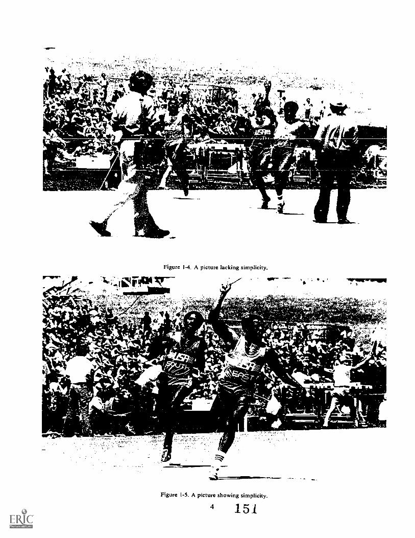
7114411.
Figure 1-4. A picture lacking simplicity.
- .1 iv IP v--
* 1 r
Not%44ar
17 74$ g4;44
-&k44"
t' iiP- -o-
fAm:
4
ws,
"zBov...
7W-
aFigure 1-5. A picture showing simplicity.
4 151
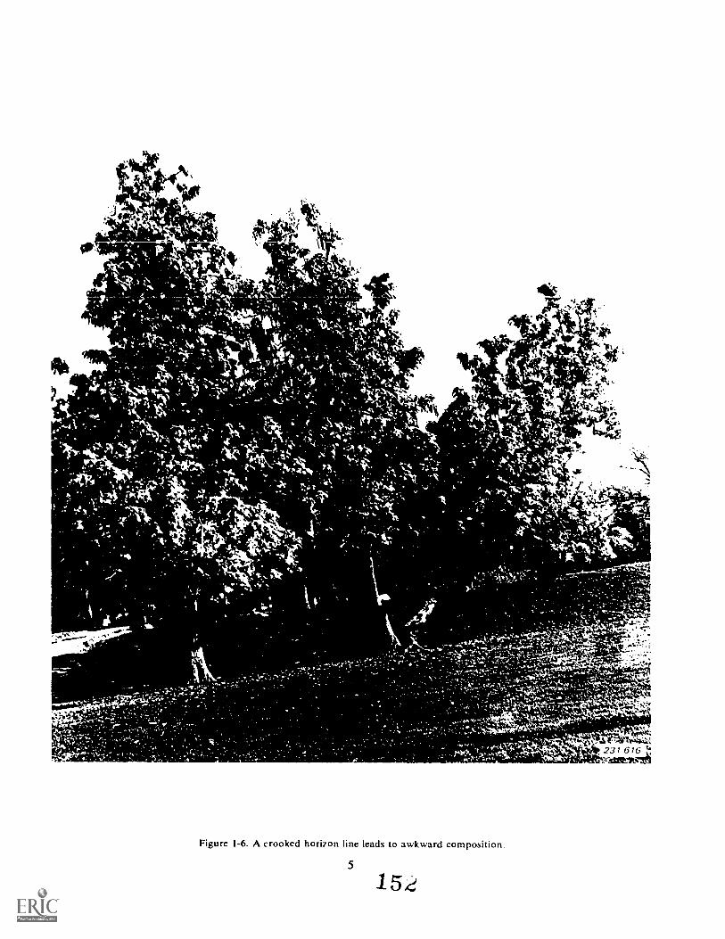
/1111111k
, 0.
tv:1,'016.
t.,
"41'
otalt4nAllird.:41
,
491 F4k
te_
Figure 1-6. A crooked horizon line leads to awkward composition.
5
1.52
4
44"i
.10.A ltst44.1:231 61b
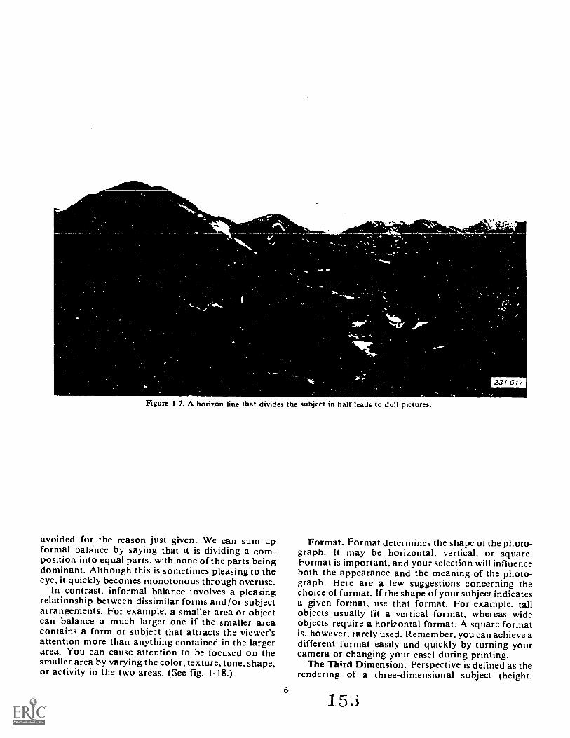
e-
Figure 1-7. A horizon line that divides the subject in half leads to dull pictures.
avoided for the reason just given. We can sum upformal balnce by saying that it is dividing a com-position into equal parts, with none of the parts beingdominant. Although this is sometimes pleasing to theeye, it quickly becomes monotonous through overuse.
In contrast, informal balance involves a pleasingrelationship between dissimilar forms and/or subjectarrangements. For example, a smaller area or objectcan balance a much larger one if the smaller areacontains a form or subject that attracts the viewer'sattention more than anything contained in the largerarea. You can cause attention to be focused on thesmaller area by varying the color, texture, tone, shape,or activity in the two areas. (See fig. 1-18.)
6
231-617
Format. Format determines the shape of the photo-graph. It may be horizontal, vertical, or square.Format is important, and your selection will influenceboth the appearance and the meaning of the photo-graph. Here are a few suggestions concerning thechoice of format. If the shape of your subject indicatesa given format, use that format. For example, tallobjects usually fit a vertical format, whereas wideobjects require a horizontal format. A square formatis, however, rarely used. Remember, you can achieve adifferent format easily and quickly by turning yourcamera or changing your easel during printing.
The Third Dimension. Perspective is defined as therendering of a three-dimensional subject (height,
153
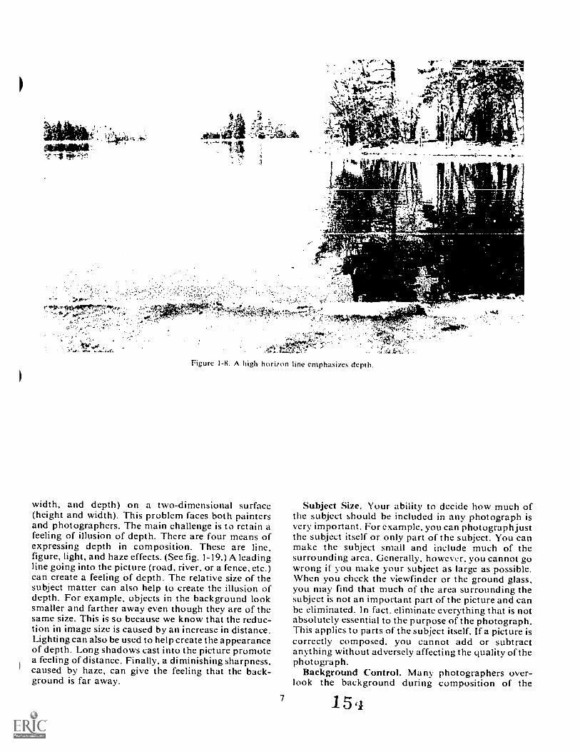
Figure I-8. A high horizon line emphasizes depth.
width, and depth) on a two-dimensional surface(height and width). This problem faces both paintersand photographers. The main challenge is to retain afeeling of illusion of depth. There are four means ofexpressing depth in composition. These are line,figure, light, and haze effects. (See fig. 1-19.) A leadingline going into the picture (road, river, or a fence, etc.)can create a feeling of depth. The relative size of thesubject matter can also help to create the illusion ofdepth. For example, objects in the background looksmaller and farther away even though they are of thesame size. This is so because we know that the reduc-tion in image size is caused by an increase in distance.Lighting can also be used to help create the appearanceof depth. Long shadows cast into the picture promotea feeling of distance. Finally, a diminishing sharpness.caused by haze, can give the feeling that the back-ground is far away.
7
Subject Size. Your ability to decide how much ofthe subject should be included in any photograph isvery important. For example, you can photograph justthe subject itself or only part of the subject. You canmake the subject small and include much of thesurrounding area. Generally, however, you cannot gowrong if you make your subject as large as possible.When you check the viewfinder or the ground glass,you may find that much of the area surrounding thesubject is not an important part of the picture and canbe eliminated. In fact, eliminate everything that is notabsolutely essential to the purpose of the photograph.This applies to parts of the subject itself. If a picture iscorrectly composed. you cannot add or subtractanything without adversely affecting the quality of thephotograph.
Background Control. Many photographers over-look the background during composition of the
15,1

ot" tt.
vive"
Figure 1-9. A low horizon line emphasizes height.
8 155
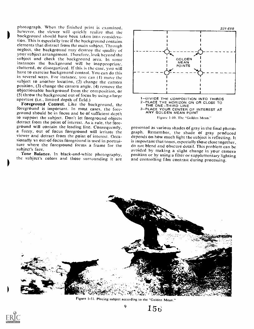
photograph. When the finished print is examined.however, the viewer will quickly realize that thebackground should have been taken into considera-tion. This is especially true if the background containselements that distract from the main subject. Throughneglect, the background may destroy the quahty ofyour subject arrangement. -therefore, look beyond thesubject and cheek the background area. In someinstances the background will be inappropriate,cluttered, or disorganized. If this is the case, you willhave to exercise background control. You can do thisin several ways. For instance, you can ( I) move thesubject to another location, (2) change the cameraposition, (3) change the camera angle, (4) remove theobjectionable background from the composition, or(5) throw the background out of focus by using a largeaperture (i.e., limited depth of field.)
Foreground Control. Like the background, theforeground is important. In most cases, the fore-ground should be in focus and be of sufficient depthto support the subject. Don't let foreground objectsdetract from the point of interest. As a rule, the fore-ground will contain the leading line. Consequently,a fuzzy, out of focus foreground will irritate theviewer and detract from the point of interest. Occa-sionally an out-of-focus foregrOund is used in portrai-ture where the foreground forms a frame for thesubject's face.
Tone Balance. In black-and-white photography,the subject's colors and those surrounding it are
GOLDENMEAN
POINTS
231-619
1DIVIDE THE COMPOSITION INTO THIRDS2PLACE THE HORIZON ON OR CLOSE TO
THE ONETHIRD LINE3PLACE YOUR CENTER OF INTEREST AT
ANY GOLDEN MEAN POINTFigure I-I0. The "Golden Mean.-
presented as various shades of gray in the final photo-graph. Remember, the shade of gray produceddepends on how much light the subject is reflecting. Itis important that tones, especially those close together,do not blend and obscure detail. This problem can beavoided by making a slight change in your cameraposition or by using a filter or supplementary lightingand controlling film contrast during processing.
9 1 5 6
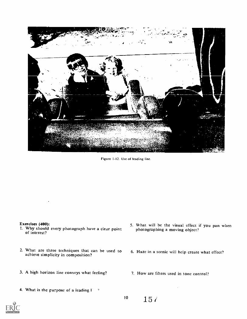
'Of
T.W,Xtit.
4A°.'
st$',
,
A
A
/..0 1.11.
. .
4
c, ,
Figure 1-12. Use of leading line.
Exercises (400):I. Why should every photograph have a clear point
of interest?
2. What are three techniques that can be used toachieve simplicity in composition?
_1111111._
AoloPik
5. What will be the visual effect if you pan whenphotographing a moving object'?
6. Haze in a scenic will help create what effect?
3. A high horizon line conveys what feeling? 7. How are filters used in tone control'?
4. What is the purpose of a leading 1 ?
10 15
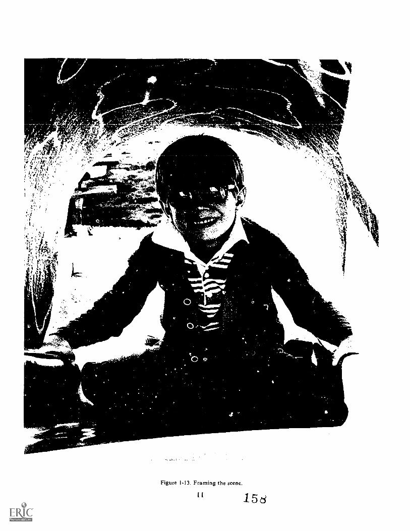
3,
, ..r .........,.... .... ,...... , 0 iS 5
lerli* ''''..:.-'it r
. ', ." : 'Vr, ' -....,, :..r.'
....... 1 ., - .
, : -1 . ...a AP,.4 . : f .y. . 4a- , 1 o-0 - ,, 400111M., ^ -
4:,L0
...1111n_
.00a
is,. s , k"k,_,` ik
-\x - A. , , k
v4q,'1iL4
ip
Figure 1-13. Framing the scene.
11 15d
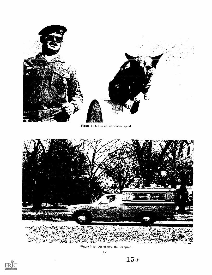
;f,b
r
..ttlkst
t'e
/3
(,C.L4410',
fir"$,
.11,. .yA11' I
1,
14.4 VA;4.
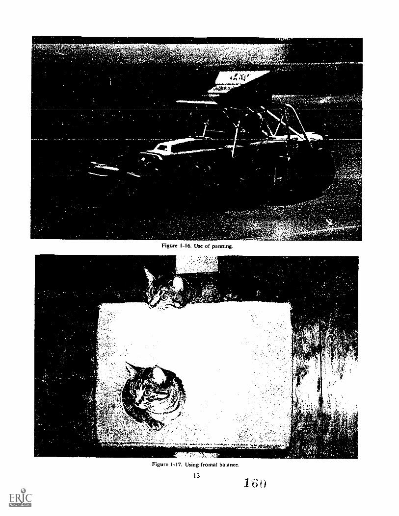
4
14414P4,4.
41,4$4;2-'
4ie
Figure 1-16. Use of panning.
st..44.....4
44.s.
4.4await
esti+k:,-E
Figure 1-17. Using fromal balance.
13
160
;.,
I'
1
_
'4 '^'w t, '
,
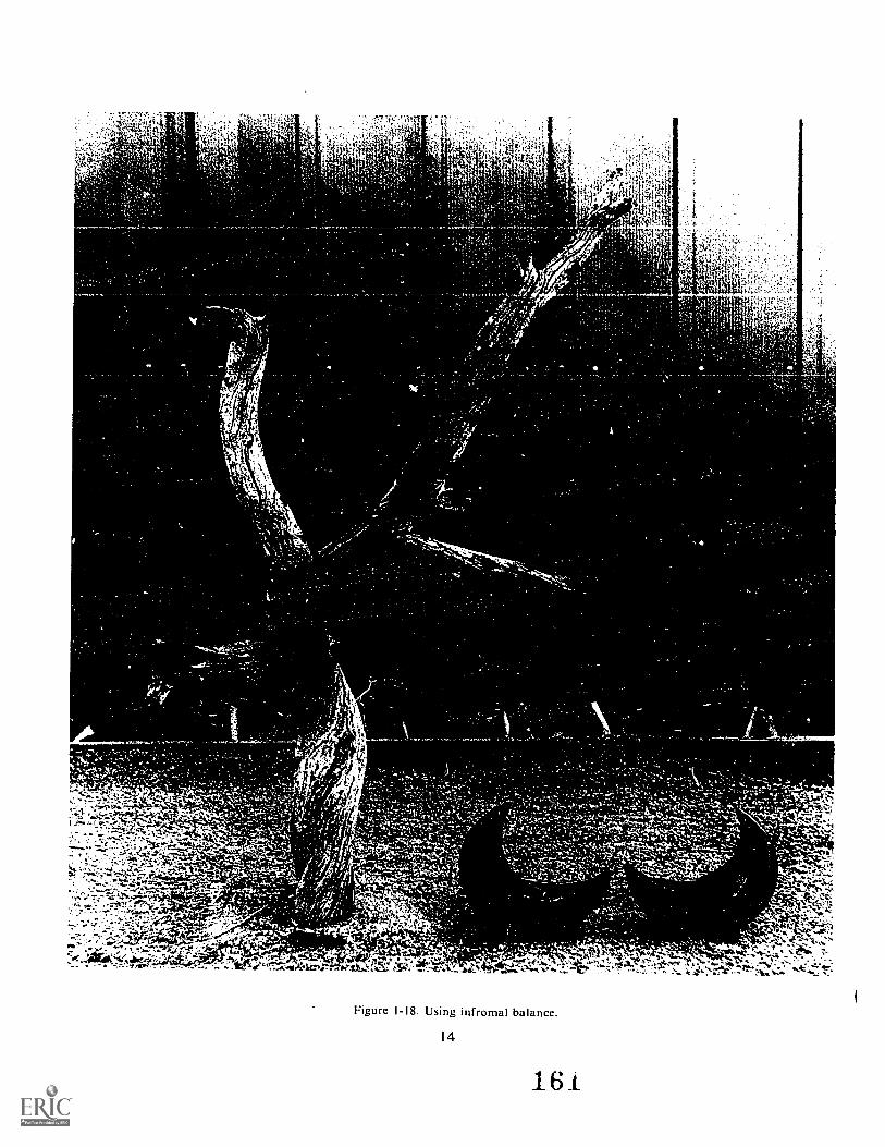
41'
,'0" ,
t.
.....4 ,
I....
our........"
,
WV., .. ,, s-,.... 44... it,,....-
(74,..'1.-- .
=.$
,'tab,
.r
VeI 0.sc '_ .^: . ,..4eASAst,A
.,1.0:11..
1 -
. 4,
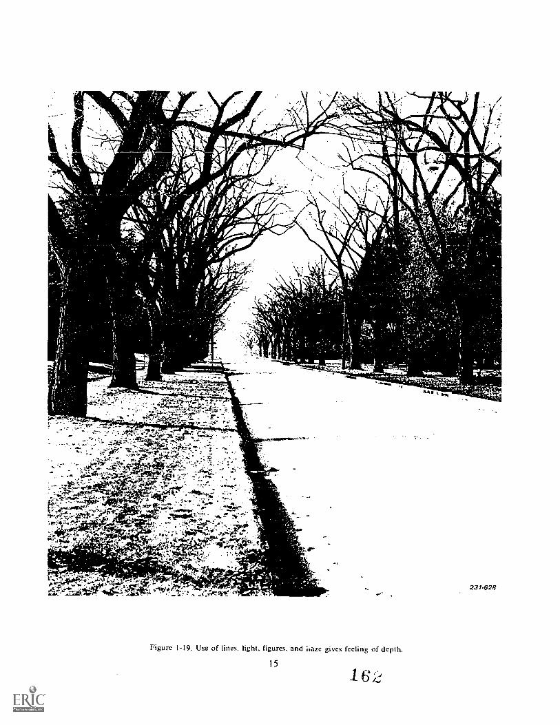
0- .
-
r-
7 f ke
Velge0.77.I\ie" ;as r
\I t
'a1.1
-
,
-
--Z.*, ..
. , 0A:':!... :-.0?".,,,47-,-.:011,1,T,,,,,,..,:47.--
I ....--:'," ......, ,;.g.,. .....r,,,..,,,..z.fr..4199,!,. ,..."..,,,.: .:-....
---Te'--..' ir.:...-- . 4
t-'4;: r,li 4ta.4104.- 7 :-..-'....,.- ;
....":P.4 ''-;:q. -1 PZ. ; '411117.t-44%.4 ..,,,:.e. "Y ''....L. 4.01t"' ,S;AwAf.
'....i:'.
-k .., -
INIONIoSsou-,
.4
:237-628
Figure 1-19. Use of lines, light, figures. and ;laze gives feeling of depth.
151
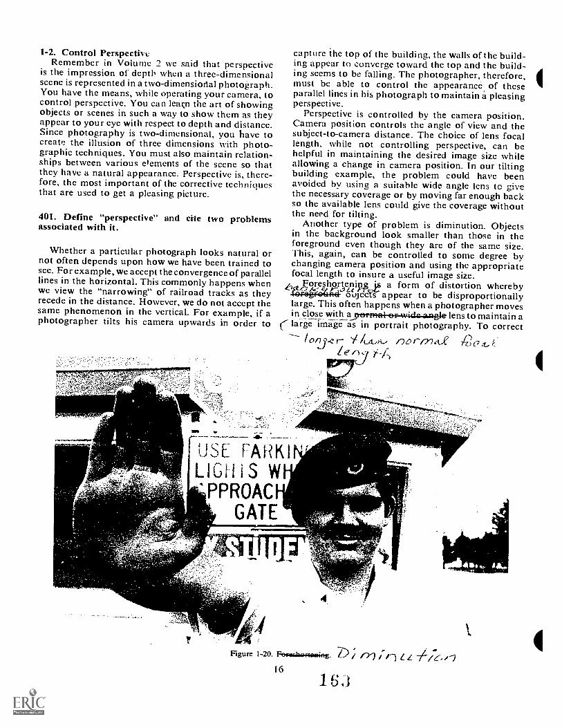
1-2, Control PerspectiveRemember in Volume 2 we said that perspective
is the impression of depth when a three-dimensionalscene is represented in a two-dimensional photograph.You have the means, while operating your camera, tocontrol perspective. You can leaçn the art of showingobjects or scenes in such a way to show them as theyappear to your eye with respect to depth and distance.Since photography is two-dimensional, you have tocreate, the illusion of three dimensions with photo-graphic techniques. You must also maintain relation-ships between various Oements of the scene so thatthey have a natural appearance. Perspective is, there-fore, the most important of the corrective techniquesthat are used to get a pleasing picture.
401. Define "perspective" and cite two problemsassociated with it.
Whether a particular photograph looks natural ornot often depends upon how we have been trained tosee. For example, we accept the convergence of parallellines in the horizontal. This commonly happens whenwe view the "narrowing" of railroad tracks as theyrecede in the distance. However, we do not accept thesame phenomenon in the vertical. For example, if aphotographer tilts his camera upwards in order to
capture the top of the building, the walls of the build-ing appear to converge toward the top and the build-ing seems to be falling. The photographer, therefore,must be able to control the appearance of theseparallel lines in his photograph to maintain a pleasingperspective.
Perspective is controlled by the camera position.Camera position controls the angle of view and thesubject-to-camera distance. The choice of lens focallength, while not controlling perspective, can behelpful in maintaining the desired image size whileallowing a change in camera position. In our tiltingbuilding example, the problem could have beenavoided hy using a suitable wide angle lens to givethe necessary coverage or by moving far enough backso the available lens could give the coverage withoutthe need for tilting.
Another type of problem is diminution. Objectsin the background look smaller than those in theforeground even though they are of the same size.This, again, can be controlled to some degree bychanging camera position and using the appropriatefocal length to insure a useful image size.
Xv9hp_roteineipf_ is' a form of distortion wherebyoujecYr appear to be disproportionally
large. This often happens when a photographer movesin close with arreprme4-ef-wide.a.ngle lens to maintain a
Ze c),
[USE FARKIN'LIGHiS'PPROACP
GATE
,Figure 1-20. Feraciaaftiming. / rY)
16
16J
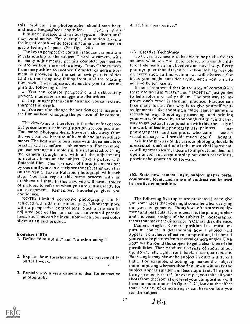
this "problem" the photographer should step backand use a tenterySocal length lens.
It must be stressed that various types of "distortions"may be effective. For example, diminution gives afeeling of depth while foreshortening can be used togive a feeling of space. (See fig. 1-20.)
The key to perspective control is the camera positionin relationship to the subject. The view camera, withits many adjustments, permits complete perspectivecontrol without the need to always "move" the camerafrom one position to another. Complete camera move-ment is provided by the set of swings, tilts, slides(shifts), the rising and falling front, and the rotatingfilm back. These adjustments enable you to accom-plish the following tasks:
a. You can control perspective and deliberatelyprevent, moderate, or exaggerate distortions.
b. In photographs taken at an angle, you can extendsharpness in depth.
c. You can also change the position of the image onthe film without changing the position of the camera.
The view camera, therefore, is the choice for correc-tive procedures to achieve distortion free composition.Too many photographers, however, shy away fromthe view camera because of its bulk and many adjust-ments. The best way to be at ease with the camera is topractice with it before a job comes up. For example,you can arrange a simple still life in the studio. Usingthe camera straight on, with all the adjustmentsin neutral, focus on the subject. Take a picture withPolaroid film. Then use each of the adjustments oneby one until you can ciearly see the effect that each hason the result. Take a Polaroid photograph with eachstep. You can repeat this same process with anarchitectural shot. In this way, you will have a folderof pictures to refer to when you are getting ready foran assignment. Remember, knowledge gives youconfidence.
NOTE: Limited corrective photography can beachieved with a 35-mm camera (e.g., Nikon) equippedwith a perspective control lens. Such a lens can beadjusted out of the normal axis to control parallellines, etc. This can be invaluable when you need colorslides as an end product.
Exercises (401):I. Define "diminution" and "foreshortening."
2. Explain how foreshortening can be prevented inportrait work.
3. Explain why a view camera is ideal for correctivephotography.
17
4. Define "perspective."
1-3. Creative TechniquesTo be creative means to be able to be productive: to
achieve what was not there before: to assemble dif-ferent elements in an effective and novel way. Everyphotographer should try to be as thoughtful as possibleon every shot. In this section, we will discuss a fewideas you might consider trying when you wish toachieve better results.
It must be stressed that in the area of compositionthere are no firm "DO's" and "DON'Ts," just guidesto help solve a vi al problem. The best way to im-prove one's "eye" is through practice. Practice cantake many forms. One way is to give yourself "self-assignments," like shooting a "little league" game in arefreshing way. Shooting, processing, and printingyour work, followed by a thorough critique, is the bestway to get better. In conjunction with this, the Idy ofthe work of leading photographers, painters -ma-photographers, and scuiptors, who comr cate avisual message, will provide much food f .nought.
While the mastery of the various photo& aphic skillsis essential, one's attitude is the most vital ingredient.A willingness to learn, a desire to improve and demandupon oneself to accept nothing but one's hest efforts,provide the power to go forward.
402. State how camera angle, subject matter parts,equipment, focus, and tone and contrast can be usedin creative composition.
The following five topics are presented just to giveyou some ideas that you might consider when carryingout your assignments. Though we often stress equip-ment and particular techniques, it is the photographerand his visual insight of the subject in photographicterms that make the difference. YOU are the difference.
Camera Angles. Camera position is a most im-portant choice in determining how a subject willappear. To achieve effective composition, it is best ifyou can take pictures from several camera angles. Do a3600 walk around the subject to get a clear idea of thepossibilities. Then produce a variety of shots. Shootup, down, left, right, front, back, three-quarters, etc.Each angle may show the subject in quite a differentlight. For example, shooting up makes the subjectmore imposing whereas shooting down will make thesubject appear smaller and less important. The pointbeing stressed is that if, for example, you take all yourshots from the front at eye level your compositions willbecome monotonous. In figure 1-21, look at the effectthat a variety of camera angles can have on how yousec the subject.
164
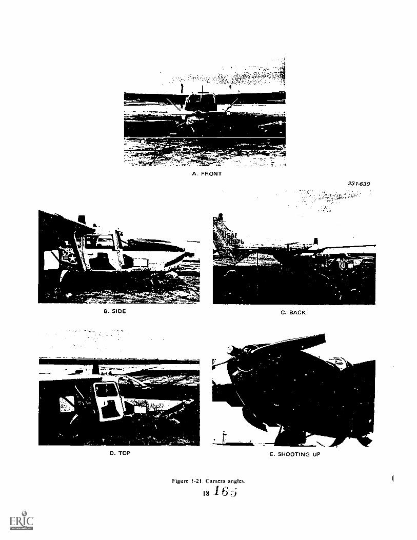
SW-
-
B. SIDE
A. FRONT
231-63 0
C. BACK
V;
D. TOP
Figure 1-21. Camera angles.
18 1 6
E. SHOOTING UP
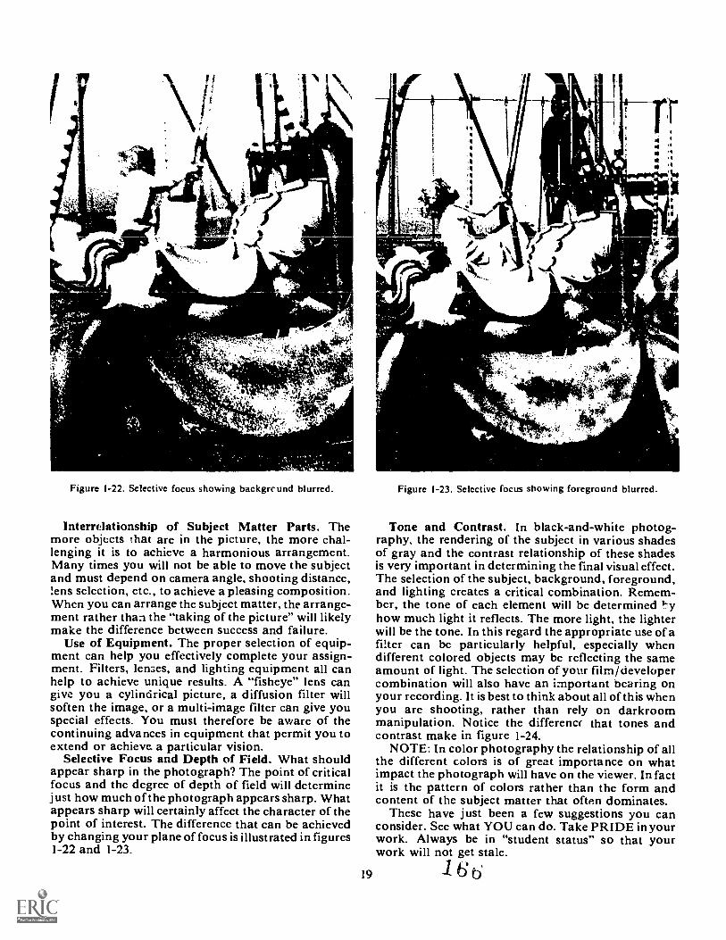
MC
41
sANN%
Figure 1-22. Selective focus showing backgrcund blurred.
Interrdationship of Subject Matter Parts. Themore objects that are in the picture, the more chal-lenging it is to achieve a harmonious arrangement.Many times you will not be able to move the subjectand must depend on camera angle, shooting distance,tens selection, etc., to achieve a pleasing composition.When you can arrange the subject matter, the arrange-ment rather than the "taking of the picture" will likelymake the difference between success and failure.
Use of Equipment. The proper selection of equip-ment can help you effectively complete your assign-ment. Filters, lenses, and lighting equipment all canhelp to achieve unique results. A "fisheye" lens cangive you a cylindrical picture, a diffusion filter willsoften the image, or a multi-image filter can give youspecial effects. You must therefore be aware of thecontinuing advances in equipment that permit you toextend or achieve a particular vision.
Selective Focus and Depth of Field. What shouldappear sharp in the photograph? The point of criticalfocus and the degree of depth of field will determinejust how much of the photograph appears sharp. Whatappears sharp will certainly affect the character of thepoint of interest. The difference that can be achievedby changing your plane of focus is illustrated in figures1-22 and 1-23.
19
Figure 1-23. Selective focus showing foreground blurred.
Tone and Contrast. In black-and-white photog-raphy, the rendering of the subject in various shadesof gray and the contrast relationship of these shadesis very important in determining the final visual effect.The selection of the subject, background, foreground,and lighting creates a critical combination. Remem-ber, the tone of each element will be determinedhow much light it reflects. The more light, the lighterwill be the tone. In this regard the appropriate use of afilter can be particularly helpful, especially whendifferent colored objects may be reflecting the sameamount of light. The selection of your film/developercombination will also have an important bearing onyour recording. It is best to think about all of this whenyou are shooting, rather than rely on darkroommanipulation. Notice the differenet that tones andcontrast make in figure 1-24.
NOTE: In color photography the relationship of allthe different colors is of great importance on whatimpact the photograph will have on the viewer. In factit is the pattern of colors rather than the form andcontent of the subject matter that often dominates.
These have just been a few suggestions you canconsider. See what YOU can do. Take PRIDE in yourwork. Always be in "student status" so that yourwork will not get stale.
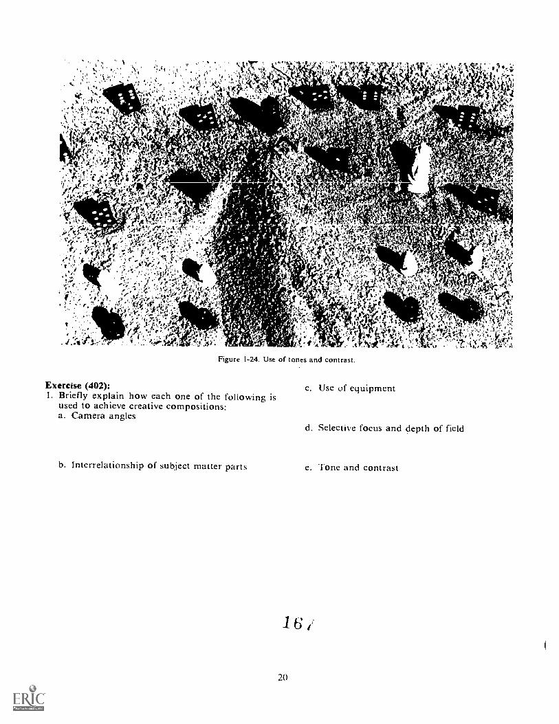
Figure 1-24. Use of tones and contrast.
Exercise (402):I. Briefly explain how each one of the following is
used to achieve creative compositions:a. Camera angles
b. Interrelationship of subject matter parts
20
c. Use of equipment
d. Selective focus and depth of field
e. Tone and contrast
,

General Assignments
A PHOTOGRAPHIC WORK order simply states adesired result that must be provided. Your super-visor's task is to determine the course of action to befollowed to give the user the best quality work avail-.able at the least cost to the Air Force. As you canunderstand, this requires planning for the entire task.
Each photographic facility has its own set of con-ditions, such as personnel, workload, and equipment.Photography is not a field where there is only one setmethod to accomplish each task. Therefore, manyfactors must be considered in determining how a jobis to be carried out.
It is important that when are called upon to carryout a mission, you are aware of what is required. Inthis way you can apply the skills you are mastering toget the necessary results. In this chapter, we will dis-cuss many of the various types of missions you may beassigned to do and some of the basic techniques youmay want to use.
2-1. Mission PlanningWhen a basketball coach calls a time out it is to
plan the next line of attack. A football coach does thesame thing. Before you drive from Los Angeles toOmaha, you would look at a map and plan your route.Before you shoot a photo mission you must also planwhat you are going to do and when you need to do it.
This section deals with your Planning. We includecoordination, selecting and inspecting equipment, andloading film holders. All of these factors are importantto your mission. So remember, plan ahead.
503. List the items of information needed to coordinatewith the requester and/or Office of Information (Op.
Coordination. Suppose you are invited to a friend'shouse for a party. You will want to know if it is acasual party, a costume party, or a pool-side party.You probably don't want to make a fool of yourself.So you will coordinate with the party giver. You reallydon't want to show up in your swimming suit for a sit-down dinner.
In nearly everything you do, you have some type ofcoordination to do. In photography you also must
21
CHAPTER 2
coordinate. Suppose your iequest calls for shots ofsome wall charts. Do you know how big the chartsare? Are there plenty of electrical outlets in the area?Is there enough room for you to move about?
All of these questions and more must be answeredbefore you show up. This is your coordination withthe requester. Find out exactly what is wanted andunder what conditions you will have to work.
You need to find out whom to report to. You needto know if transportation will be provided or if youhave to get there yourself. Most of this information isavailable on the AF Form 833, Request for Audio-visual Services (remember from Volume 1), but itnever hurts to do some extra coordination.
Your request may come from the Office of Infor-mation (01); you still need to do some coordinating.Answer all of the questions just asked and somemore. Will an 01 person be with you? Will the 01provide transportation? Is there a short suspense?Will you need proofs?
The whole point of coordination is defined in thedictionary "As the state of being in harmonious ad-justment." That is, you know what is expected of you,what you can expect from the requester, and whatthe final outcome will be.
Exercises (403):1. List three things you should find out when you
coordinate with the requester or 01
2. What Air Force form will assist you the most inyour mission coordination?
404. List the factors which must be considered inselecting equipment and materials for an assignmentof any type.
This next section is a continuation of your coordina-tion. When preparing for an assignment you should
16d
consider three factorsthe product desired, the shoot-ing conditions, and the tirnt requirements.
Product Desired. Whether the requester wantsslides, color, or black-and-white prints, or combina-tions of these will set limits on your choice of film,processing, printing, and camera equipment. For ex-ample, slides require the use of a 35-om camera,reversal color film, and appropriate r ,:essing. Thisfilm restriction alone may preclude youi choice to onecamera. The requester may instead want both colorand black-and-white prints. Color negative film cangive you both products, and it is available in a widevariety of formats, so your choice of a camera becomesmuch greater.
Shooting Conditions. The who, what, where, when,and why of your assignment will be the biggest fac-tors in your equipment and film choice. A few ex-amples will illustrate the problem. An architecturalassignment normally calls for a view camera and thenecessary cut film. A crash and accident can be besthandled with a press camera and roll film or filmpacks. A football game is easiest to shoot with a 35-mm refiex camera and a variety of lenses. Whetherthe event is indoors or outdoors, daylight or night-time, or on a beautiful sunny day or in downpouringrain will, for example, call for decisions on filmspeeds and accessory lighting.
Each job should be analyzed in terms of additionalequipment as well. A view carnera, for example, re-qu:les a sturdy tripod and a cable release. Filters areoften required for accurate tonal rendition or colorbalance. You should always carry a properly workinglight meter. Remember, there is nothing more embar-rassing than to travel for an hour or two to the shoot-ing spot, get set up, and then realize that you haveforgotten a piece of equipment that will make thedifference between a "half-baked" job and success.
Time Requirements. Considerations of time mayrequire particular equipment solutions. For example, aquick identification picture may be satisfied with aninstant picture camera. A job that requires only a fewshots, but has a "short fuse" on delivery may be besthandled with a 4 x 5 press camera and cut film.
It must be stressed that you should carefully analyzeyour work order prior to going out on a job. Youshould develop a standardized checklist that should befollowed so that you have the equipment you need withyou. Such preparation will save you time in the longrun because it will reduce the number of reshoots andit will prevent your shop from getting a poor reputa-tion.
Exercise (404):1. List the three factors that should be considered
when choosing film and equipment. Briefly explainwhy each is important.
405. Cite techniques and procedures used ir. the in-spection and testing of photographic equipment.
22
Visual Checks. Visual checks of camera and kibequipment give a good indication of their conditionand usability. This visual check shouldn't be a quickg,k.nce but a thorough examination of condition. Forexample, suppose you are checking a camera bellows.A casual examination of the item may indicate in-correctly that the bellows is in perfect condition.Instead, extend the bellows to its maximum and, in adarkened room, place a light inside. If you cannot seeany light leaks, the bellows is in good condition.Examine all items with the thought in mind thatsomething is wrong and prove to yourself that they areall in satisfactory condition. It is surprising how manypitfalls you can avoid by looking for trouble in ad-vance.
Operational Checks. Operationll checks should beperformed on each item of equipment. There is a dan-ger of losing a photograph by a mechanical malfunc-tion. This applies to lab equipment as well as thecamera and accessories. Any item that must functionto contribute to the final product should be consideredas a possible trouble spot. For example, without afunctioning focal plane shutter a 35-mm reflex cameracan become a useless object. Therefore, you shouldcheck the camera shutter very carefully prior togoing out on a mission.
There is a tendency to let seldom-used items, suchas tripods and filters, slip by in the initial test. We mayuse a press camera daily and yet use the filters ortripod less often. Don't let such usage lead you into asense of false security. Check each item against achecklist that you have prepared.
Preventive Maintenance. Preventive maintenancemight be defined as those minor maintenance pro-cedures which are performed to prevent excess wearor other damage to equipment. A small amount of oilon a squeaky bearing may prevent such a bearingfrom becoming damaged. Such preventive main-tenance is mainly up to you and your common sense.It may include simple techniques such as tightening aloose screw or greasing a gear. Such maintenance willprevent costly breakdowns. Let us consider threegeneral categories of preventive operator mainte-nanceadjustments, cleaning, and lubrication.
Adjustments. Adjustment.. must be made period-ically if top quality results are to be expected fromyour camera and lab equipment. Technical manualsfor each piece of equipment contain the proceduresfor making any required adjustments such as zeroing alight meter needle. When you do make an adjust-ment, be sure you follow the proper procedures.
Cleaning. All equipment, whether it is constructedfrom wood, metal, glass, or plastic, should be keptclean. Dust or dried chemicals can raise havoc in anyphotographic process, from the beginning to the finalproduct. All cleaning should be done with the ap-propriate cleanser for what is being cleaned.
Lubrication. Periodic lubrication of any functionalcamera and lab equipment is a necessity. Points wherefriction is created will wear any time the correctamount or correct viscosity of the lubricant is not
1 6 zi
maintained. On any equipment, the unit, its location,the method of application, the lubricating period, andthe type of lubricant arc specified in the applicabletechnical manual.
NOTE: Remember, the extent of operator main-tenance may vary from one laboratory to another.Limitations are due to the availability of maintenancepersonnel, the time it takes to send out a piece ofequipment for repair, and the applicable regulationsand technical orders which spell out areas of respon-sibility.
Exercises (405):I. What is the purpose of a visual check?
2. Why are operational checks important?
3. What is the advantage of performing preventivemaintenance?
4. List and briefly explain three teci,niques that areapplied in preventive maintenance.
5. What limitations can there be on operator main-tenance?
406. Point out principles and techniques pertaining tofilm loading procedures.
Cut Film Holders. Of the various types of filmsavailable, cut film is often used in the photo lab.Each sheet is independent of the others. One sheetcan be exposed and processed by itself as opposed toroll film which cannot be economically exposed andprocessed for only one shot. Since many of yourphotos will be taken on cut film, you must learn howto load a cut film holder.
Preparation. Since holders must act as lightproofcontainers for the film, it is important that each slidebe checked for breaks or cracks along the edges. Thetwo hinged endgates of each holder should be openedand inspected for tears and holes. Replace each dark-slide by placing its leading edge squarely into thelight trap opening (never with one corner only andpushing diagonally) and by pushing evenly until theslide is seated in the groove of the closed endgate.
23
At this point and throughout your photographictraining, bear in mind that cleanliness in all opera-tions is a "must." Film is manufactured and packagedunder sterile or "white-glove" conditions to assureits frcedom from all defects. The loading room mustbe lightproof, clean, and dust free; the bench ortable on which loading is performed should be cleanedwith a damp cloth.
Remove dust from the darkslides of a film holderbefore withdrawing them through the light trap. Thenuse a soft, camel's-hair brush to clean the insides ofeach film holder. After cleaning the holders anddarkslides, reinsert the slides with the silver side ofthe tab facing outward. Push the darkslides in justshort of the point at which the slide begins to cover thefilm area. Stack the holders in piles that are con-venient to reach. Then remember where you put thembecause you will have to find them again after youturn the lights out.
Film. Cut film is packed in boxes containing any-where from 10 to 100 sheets of film. Sometimes,sheets of black paper separate each sheet of film. Thefilm is protected from bending and cracking by twopieces of cardboard. The entire package is wrapped ina single (or double) thickness of black paper for pro-tection against light. To protect the film from outsidemoisture, the entire inner package is sealed in eithermetal or plastic foil. The sealed package is then putinto a three-part, light-tight, cardboard box that has aseal of its own.
You must be careful when removing film from itsbox to prevent fingerprints, scratches, dust, or lintfrom ruining the film. To do this, always handleany sensitized material by its extreme edges only. Ifyour hands perspire freely, rinse them in cool waterand dry thoroughly on a clean towel before handlingfilm.
Each sheet of cut film is notched along one edgeaccording to a code established by the manufacturer.The notching code serves two purposes. First, it iden-tifies the film you are loading; second, it helps you toidentify the emulsion side of the film while loading orprocessing. In order for you to load a holder correctly,you must know which side of the film is the emulsionside.
Loading. Typical film notches are shown in figure2-1. When the film is held vertically with its notchesin the upper right-hand corner, its emulsion side willface you and can be slipped into the holder in its cor-rect position. If the film is held horizontally, thenotch will be in the lower right-hand corner. In eithercase, make sure that the sheet of film is under the lipson either side of the holder's frame and just below thelight trap. When the hinged endgate is pressed intoplace, the film base will lie flat against the metalplate inside the holder. If the film is not seated underthe lip by the light trap, the endgate will not closefully. Figure 2-2 shows how to load each sheet of film.
As each side of the holder is loaded, push the dark-slide in place until it is seated in the groove of theendgate. Only when the darkslide is inserted squarely
1? I
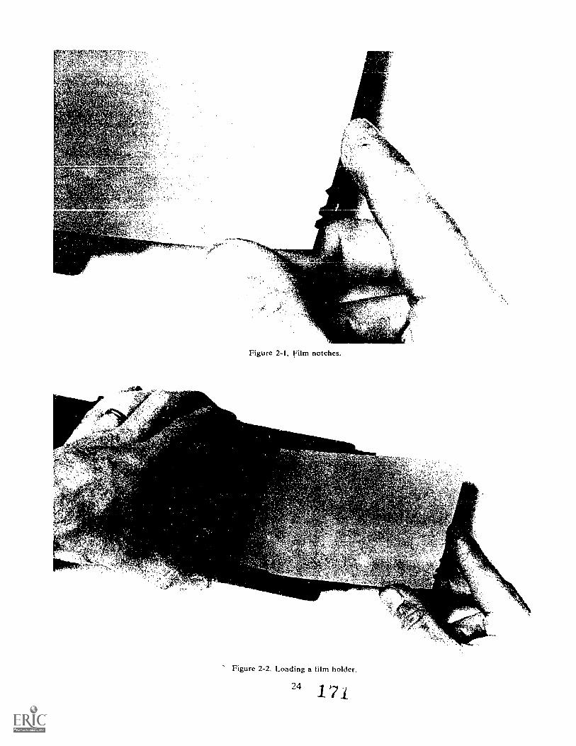
Figure 2-1, Film notches.
Figure 2-2. Loading a film holder.
24 /
win it slide in place easily. Before inserting the dark-slide into the holder, check the raised dots along themetal strip at the top of each slide to insure that theyare facing outward. These dots are only on the silverside of this metal strip, which indicates that the holderis loaded with unexposed film.
When all holders are loaded with fresh film andwhen their darkslides are replaced, turn the smalllocking pins so that each pinhead projects over aslide. The locking pin prevents a darkslide frombeing accidentally withdrawn and ruining the filmwhen you are handling the holder on a mission.
After removing the required sheets of cut film fromthe inner package, carefully rewrap the remainingfilm in the black wrapping paper and return it to thecardboard box. Turn the lights on; then tape the boxshut and label it with the number of cut-film sheetsremaining, the date, and your name.
Film Pack Holders. A film pack is a thin metal con-tainer which holds 12 or 16 very thin sheets of film.Each sheet of film is attached to an opaque sheet ofblack paper called a tab. Before use, all of the sheetsof film face toward the opening in the front of themetal container. The pack of film is held in place by aspring-loaded pressure plate. Between the first sheetof film and the opening in the frame there is a pro-tective cover with its own tab.
Before you can use the film pack, you must removethe protective cover over the first sheet of film bypulling on the attached (0) tab. Instantly, the pres-sure plate pushes the first sheet of film up againstthe retaining frame surrounding the opening. Theblack paper on the back of each sheet of film protectsthe sheet behind it from exposure by transmittedlight. After exposing the first sheet of film, pull thenumber 1 tab. This pulls the sheet of exposed filmaround the end of the film pack and positions it behindthe remaining film. The diagram in figure 2-3 showsthe principle of the film pack. As the first film is pulledaround to the back, the second sheet is uncovered,and the pressure plate forces it into the correct posi-tion for exposure. This procedure is continued untilthe last piece of film has been exposed and has beenpulled to the rear of the pack. As you pull the lasttab, the pressure plate spring forces the pressureplate into the pack opening, creating a light-tight seal.
UNEXPOSEDFILM TABS
In order to use the film pack, you must place it intoa film pack adapter as shown in figure 2-4. This pro-cedure is really rather simple. All you have to do isrelease the spring catches, open the adapter, and putthe film pack into place. Remember to have the open-ing of the film pack container facing the opening ofthe adapter.
Roll Film Holders. Some Air Force cameras are de-signed primarily for using sheet film, but specialholders are available to adapt such cameras to handleroll film. Other cameras are designed specifically forroll film with built-in or detachable film holders. Ineither case you will have to load the roll film holder.Typical roll film holders are shown in figure 2-5.
The front part of the holder fits flat against the backof the camera. A darkslide permits you to remove theholder from the camera in the middle of a roll of filmwithout exposing the film. Parts of the roll film holderkeep the film in place, hold it flat, and move it fromone exposure to the next.
Since there are so many different types of roll filmholders, the following discussion will be very general.
Preparation. As with cut film holders and any otherphoto equipment, cleanliness is very important. Beforeyou load film into the magazine, clean the surfaceswhere the film will rest, make sure there are no lightleaks, and check that any parts that are supposed tomove do so freely.
Some magazines have exposure counters that haveto be set when the film is loaded. If you are using sucha magazine, be sure you set this counter where itbelongs.
Loading. All of the roll film holders have sometype of rollers or bars that you must guide the filmaround. Check the owner's manual to be sure youposition the film where it belongs. As with any cameraequipment, do not force anything on or onto the rollfilm holder.
Exercise (406):I. Complete the following statements:
a. Film holders act as containers forfilm.
b. The room used for loading film holders should be, and
METAL PRESSURE PLATE UNEXPOSED FILM PAPER BACKING
PAPER TABS
EXPOSED FILM TAB
Figure 2-3. Diagram of a film pack.
25
1
EXPOSED FILM
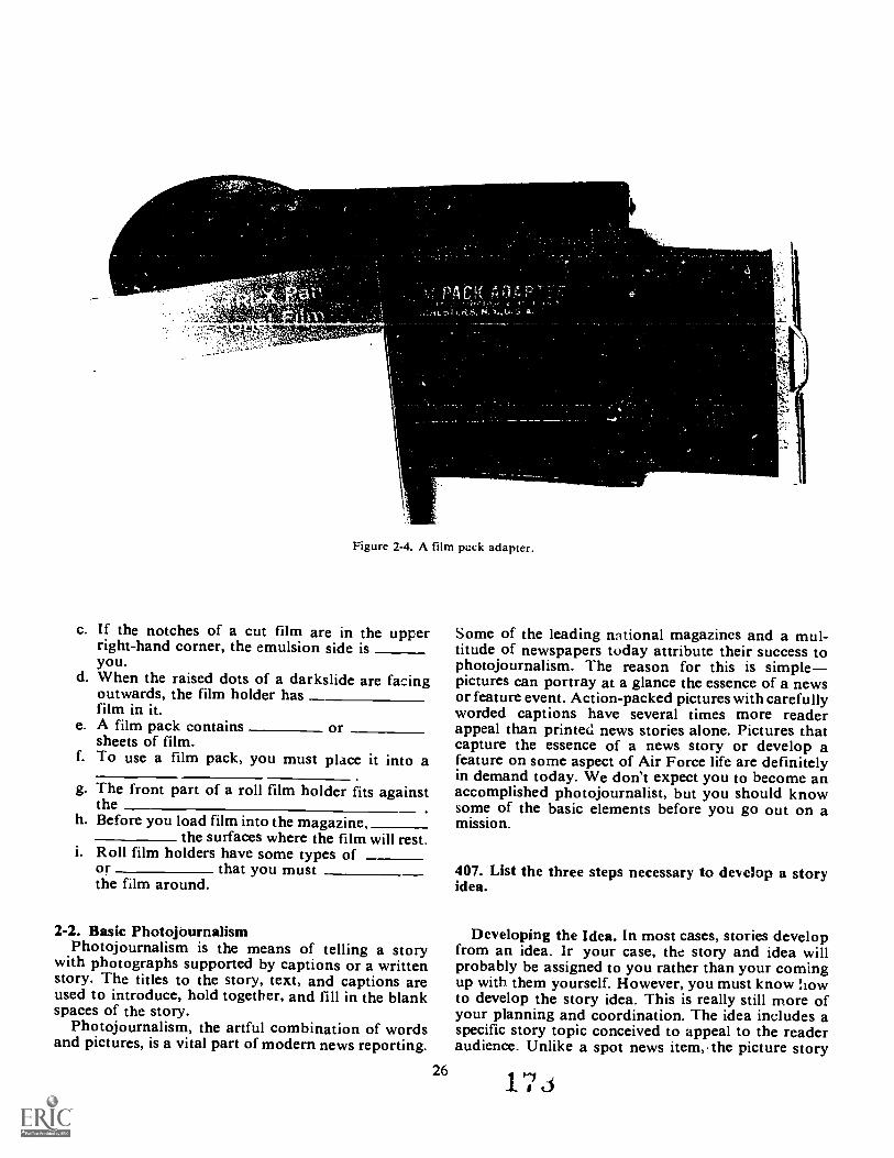
,tr
Figure 2-4. A film pack adapter.
c. If the notches of a cut film are in the upperright-hand corner, the emulsion side isyou.
d. When the raised dots of a darkslide are facingoutwards, the film holder hasfilm in it.
e. A film pack contains orsheets of film.
f. To use a film pack, you must place it into a
g.
h.
The front part of a roll film holder fits againsttheBefore you load film into the magazine,
the surfaces where the film will rest.i. Roll film holders have some types of
or that you mustthe film around.
2-2. Basic PhotojournalismPhotojournalism is the means of telling a story
with photographs supported by captions or a writtenstory. The titles to the story, text, and captions areused to introduce, hold together, and fill in the blankspaces of the story.
Photojournalism, the artful combination of wordsand pictures, is a vital part of modern news reporting.
26
Some of the leading national magazines and a mul-titude of newspapers today attribute their success tophotojournalism. The reason for this is simplepictures can portray at a glance the essence of a newsor feature event. Action-packed pictures with carefullyworded captions have several times more readerappeal than printed news stories alone. Pictures thatcapture the essence of a news story or develop afeature on some aspect of Air Force life are definitelyin demand today. We don't expect you to become anaccomplished photojournalist, but you should knowsome of the basic elements before you go out on amission.
407. List the three steps necessary to develop a storyidea.
Developing the Idea. In most cases, stories developfrom an idea. Ir your case, the story and idea willprobably be assigned to you rather than your comingup with them yourself. However, you must know howto develop the story idea. This is really still more ofyour planning and coordination. The idea includes aspecific story topic conceived to appeal to the readeraudience. Unlike a spot news item,. the picture story
1 7
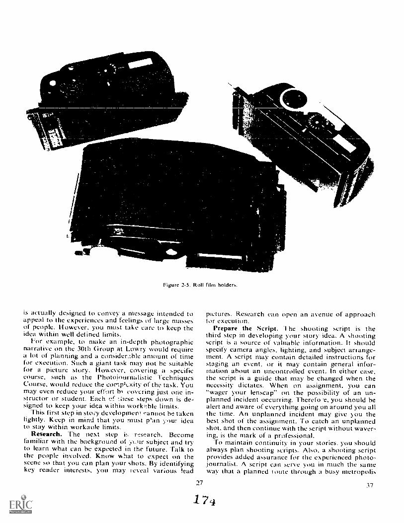
Figure 2-5. Roll film holders.
is actually designed to convey a message intended toappeal to the experiences and feelings of large massesof people. However, you must take care to keep theidea within well defined limits.
For example, to make an in-depth photographicnarrative on the 30th Group at Lowry would requirea lot of planning and a consider.:ble amount of timefor execution. Such a giant task may not be suitablefor a picture story. However, covering a specificcourse, such as the Photoiourmdistic .l'echniquesCourse, would reduce the comptLxity of the task. Youmay even reduce your effort b% covering just one in-structor or student. Each ,.!.f iiese steps down is de-signed to keep your idea w,ithin work:ble limits.
first step in stoi.y developmeu ! eannot be takenlightly. Keep in mind that you must p'an your- ideato stay within workaole limits.
Research. The next step i. r,:s,:arch. Becomefamiliar with the backgrourid ot t.ur subject and tryto learn what can be expected in the future. Talk tothe people involved. Know what to expect on thescene so that you can plan your shots. By identifyingkey reader interests, you may reveal various lead
pictures. Research can open an avenue of approachlor execution.
Prepare the Script. .1 he shooting script is thethird step in developing your story idea. A shootingscript is a source of valuable information. It shouldspecify camera angles, lighting, and subject arrange-ment. A script may contain detailed instructions forstaging an event, or it may contain general infor-mation about an uncontrolled event. In either case,the script is a guide that may be changed when thenecessity dictates. When on assignment, you can"wager your lenscap" on the possibility of an un-planned incident occurring. Therefo e, you should bealert and aware of everything going on around you allthe time. An unplanned incident may give you thebest shot of the assignment. To catch an unplannedshot, and then continue with the script without waver-ing, is the mark of a professional.
To maintain continuity in your stories. you shouldalways plan shooting scripts. Also, a shooting scriptprovides added assurance for the experienced photo-journalist. A script can serve vou in mueh the sameway that a planned route through a busy metropolis
27
1 7
37
serves an unfamiliar tra%eler. A script is a lifesaver in ama/e of action and activity.
Exercises (407):
I . What are the three steps in developing a story idea?
2. What is the most important aspect in developingyour idea'?
407a. (433for CE feedback reference only). Brieflystate how a photographic layout is developed.
Nanning the layout. A layout is the plan forplacement of photographs on a picture page. It is muchlike the plans and models made for houses. It showswhat the completed job should look like.
Layout of a picture story or photo feature, wheneverpossible, should be coordinated by the photographer andthe editor. This insures continuity and resolves problemsbefore publication.
When called upon to make a layout, obtain all the datarelative to the job. Start the layout with a number ofsmall thumbnail sketches, keeping in mind where youwill place the lead picture and supporting photographs.The lead, or key, photograph should immediately catchthe viewer's interest and lead the eye to the rest of thedisplay. It should express the central theme of the storyand he placed in a predominant position of the layout.Generally, the lead or key photograph is larger than anyof the other photographs.
Once the rough layout has been accomplished, acomprehensive layout or visual sketch can be completed.Photos are then arranged to catch the reader's eye, inaddition to the logical progression of the story.
Exercises (407a):
I. Flow do you develop a photographic layout?
2. Who should be involved in the planning stages of alayout'?
408. Indicate whether given statements correctlyreflect the writing of captions and cover stories.
A missile launching may make an exciting picture, butit fails as a news picture unless the reader can understandthe when, where, and why as well as the obvious whatand how. To fill in the spaces that the picture by itselfleaves, you need to write captions and cover stories.
Captions. There are probably as many different waysto write captions as there are photographers. These waysvary in their worth according to how well theysupplement and clarify the picture. The elements thatmake up a good caption are used by nearly all captionwriters in one form or another. We include here the fourelements and a description of each.
Explanation. The first sentence is the most importantone in a caption. lt must link the photograph to itscaption by describing the action in the photograph. Oneof the peculiarities of the first sentence is its verb form.The verb in the first sentence of a caption is usually inthe present tense. The ....ason for ihis is that photographs,like paintings and sculpture, capture one moment of timeand keep it in the present. Just as a painting depictingWashington crossing the Delaware captures that momentof history in the present for as long as the painting Itselfexists, so a photograph captures one moment of history,whether dramatic or mundane.
Another reason for using the present tense in the firstsentence is that it gives the reader a sense of immediacy,as though he were actually witnessing the event shown.Thus, a caption reads, "Airman James T. White swimsthrough swirling flood waters of the Colorado River torescue 6-year-old Ruth Gray. . . ." nas more dramaticimpact than one which reads, 'Airman James T. Whiteswam through. . . ."
One problem which arises from the use of presenttense in thc first sentence is what to do with the whenelement. To put the time element in the first sentencewould result in a sentence such as, "Steve Garvey hits aline drive to center field yesterday. . . ." Needless tosay, this is somewhat jarring to the reader and should beavoided. To alleviate this problem, the time element incaptions is usually left out of the first sentence. Thisavoid awkward sentences with a shift in tense such as theone just quoted.
Identification. The second part of the caption is theidentification. This includes the identification of allpersons and things vital to the storytelling function of thephotograph. The question of who should be identified is,of course, the biggest problem here, and only generalguidelines can be given to help the caption writer. Thereis no magic formula for every situation. Everyone shouldbe identified who is identifiable and pertinent to thestory. By identifiable, we mean a person who is notblurred or obscured or too far away for recognition. Bypertinent, we mean a person who is involved in thecentral action of the picture. lt should be noted,however, that anyone in a photograph who attracts thereader's attention should be identified. The reader'scuriosity should never be frustrated.
The next question concerning identification is where itshould be placed in the caption. The best answer to thisis that it should come as soon as possible in the caption.Many times you can identify people at the same time theaction is described. For example, in the statement''Sergeant John P. Woods sounds Taps to climaxMemorial Day ceremonies . . . ." the identification isincluded as the subject of the action. Sometimes,
27 a. 39

however, it is better to use an impersonal identificationin the first sentence. In that case, the completeidentification should come in the second sentence.
The only exception to this general rule is in the case ofgroup identification. When there are several people to beidentified in a photograph, it is better not to clutter thefirst two sentences with a list of names. This is apt todiscourage the reader from finishing the caption. Therecommended way to handle a group photograph is touse an impersonal identification in the first sentence(such as, "A group of airmen. . . .") and then list thenames in the caption. This achieves completeidentification without cluttering the important firstsentence.
The identification itself can be handled in one ofseveral ways. The idea is to handle it in the most naturaland concise manner consistent with clarity. The best way
40 28
to identify people is by action. If John Smith is passing afootball to Sam Brown, it should be obvious from thephotograph which one is passing and which one isreceiving the ball. Thus, they arc identified by theiractivity and you need not use left-to-right ideniification.
Another simple manner of identifying some membersof a photograph is by obvious contrast. If there are twoairmen and Miss America in a picture, it is not necessaryto identify Miss America as being left of center. She iswell identified by obvious contrast, and placeidentification would be superfluous.
Slightly more complex is identification byelimination. Suppose there are three people in a picture(see fig. 2-6). The general is pinning officer's bars on thcrecipient. These two are identified by their action. Theremaining person, obviously the recipient's proud wife,is identified by elimination.
1'7
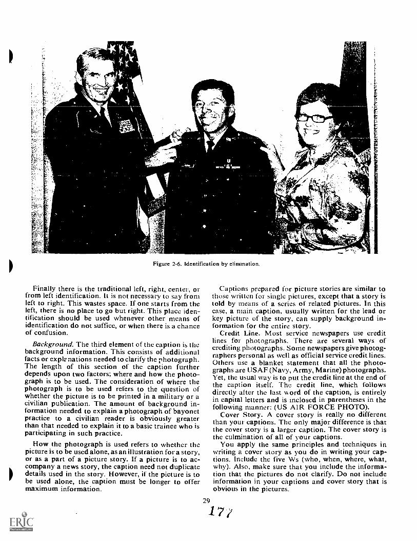
-
Figure 2-6. Identification by elimination.
Finally there is the traditional left, right, center, orfrom left identification. It is not necessary to say fromleft to right. This wastes space. If one starts from theleft, there is no place to go but right. This place iden-tification should be used whenever other means ofidentification do not suffice, or when there is a chanceof confusion.
Background. The third element of the caption is thebackground information. This consists of additionalfacts or exple nations needed to clarify the photograph.The length of this section of the caption furtherdepends upon two factors; where and how the photo-graph is to be used. The consideration of where thephotograph is to be used refers to the question ofwhether the pictute is to be printed in a military or acivilian publication. The amount of background in-formation needed to explain a photograph of bayonetpractice to a civilian reader is obviously greaterthan that needed to explain it to a basic trainee who isparticipating in such practice.
How the photograph is used refers to whether thepicture is to be used alone, as an illustration for a story,or as a part of a picture story. If a picture is to ac-company a news story, the caption need not duplicatedetails used in the story. However, if the picture is tobe used alone, the caption must be longer to offermaximum information.
Captions prepared for picture stories are similar tothose written for single pictures, except that a story istold by means of a series of related pictures. In thiscase, a main caption, usually written for the lead orkey picture of the story, can supply background in-formation for the entire story.
Credit Line. Most service newspapers use creditlines for photographs. There are several ways ofcrediting photographs. Some newspapers give photog-raphers personal as well as official service credit lines.Others use a blanket statement that all the photo-graphs are USA F (Navy, Army, Marine) photographs.Yet, the usual way is to put the credit line at the end ofthe caption itself. The credit line, which followsdirectly after the last word of the caption, is entirelyin capital letters and is inclosed in parentheses in thefollowing manner: (US AIR FORCE PHOTO).
Cover Story. A cover story is really no differentthan your captions. The only major difference is thatthe cover story is a larger caption. The cover story isthe culmination of all of your captions.
You apply the same principles and techniques inwriting a cover story as you do in writing your cap-tions. Include the five Ws (who, when, where, what,why). Also, make sure that you include the informa-tion that the pictures do not clarify. Do not includeinformation in your captions and cover story that isobvious in the pictures.
29
1
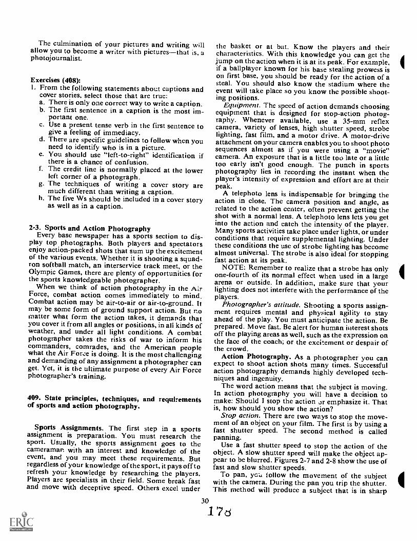
The culmination of your pictures and writing willallow you to become a writer with picturesthat is, aphotojournalist.
Exercises (408):I. From the following statements about captions and
cover stories, select those that are true:a. There is only one correct way to write a caption.b. The first sentence in a caption is the most im-
portant one.c. Use a present tense verb in the first sentence to
give a feeling of immediacy.d. There are specific guidelines to follow whcn you
need to identify who is in a picture.e. You should use "left-to-right" identification if
there is a chance of confusion.f. The credit line is normally placed at the lower
left corner of a photograph.The techniques of writing a cover story aremuch different than writing a caption.The five Ws should be included in a cover storyas well as in a caption.
8.
h.
2-3. Sports and Action PhotographyEvery base newspaper has a sports section to dis-
play top photographs. Both players and spectatorsenjoy action-packed shots that sum up the excitementof the various events. Whether it is shooting a squad-ron softball match, an interservice track meet, or theOlympic Games, there are plenty of opportunities forthe sports knowledgeable photographer.
When we think of action photography in the AirForce, combat action comes immediately to mind.Combat action may be air-to-air or air-to-ground. Itmay be some form of ground support action. But nomatter what form the action takes, it demands thatyou cover it from all angles or positions, in ali kinds ofweather, and under all light conditions. A combatphotographer takes the risks of war to inform hiscommanders, comrades, and the American peoplewhat the Air Forze is doing. It is the most challengingand demanding of any assignment a photographer canget. Yet, it is the ultimate purpose of every Air Forcephotographer's training.
409. State principles, techniques, and requirementsof sports and action photography.
Sports Assignments. The first step in a sportsassignment is preparation. You must research thesport. Usually, the sports assignment goes to thecameraman with an interest and knowledge of theevent, and you may meet these requirements. Butregardless of your knowledge of the sport, it pays off torefresh your knowledge by researching the players.Players are specialists in their field. Some break fastand move with deceptive speed. Others excel under
the basket or at bat. Know the players and theircharacteristics. With this knowledge you can get thejump on the action when it is at its peak. For example,if a ballplayer known for his base stealing prowess ison first base, you should be ready for the action of asteal. You should also know the stadium where theevent will take place so you know the possible shoot-ing positions.
EqutPment. The speed of action demands choosingequipment that is designed for stop-action photog-raphy. Whenever available, use a 35-mm reflexcamera, variety of lenses, high shutter speed, strobelighting, fast film, and a motor drive. A motor-driveattachment on your camera enables you to shoot photosequences almost as if you were using a "movie"camera. An exposure that is a little too late or a littletoo early isn't good enough. The punch in sportsphotography lies in recording the instant when theplayer's intensity of expression and effort are at theirpeak.
A telephoto lens is indispensable for bringing theaction in close. The camera position and angle, asrelated to the action center, often prevent getting theshot with a normal lens. A telephoto lens lets you getinto the action and catch the intensity of the player.Many sports activities take place under lights, or underconditions that require supplemental lighting. Underthese conditions the use of strobe lighting has becomealmost universal. The strobe is also ideal for stoppingfast action at its peak.
NOTE: Remember to realize that a strobe has onlyone-fourth of its normal effect when used in a largearena or outside. In addition, make sure that yourlighting does not interfere with the performance of theplayers.
Photographer's attitude. Shooting a sports assign-ment requires mental and physical agility to stayahead of the play. You must anticipate the action. Beprepared. Move fast. Be alert for human interest shotsoff the playing areas as well, such as the expression onthe face of the coach; or the excitement or despair ofthe crowd.
Action Photography. As a photographer you canexpect to shoot action shots many times. Successfulaction photography demands highly developed tech-niques and ingenuity.
The word action means that the subject is moving.In action photography you will have a decision tomake: Should I stop the action or emphasize it. Thatis, how should you show the action?
Stop action. There are two ways to stop the move-ment of an object on your film. The first is by using afast shutter speed. The second method is calledpanning.
Use a fast shutter speed to stop the action of theobject. A slow shutter speed will make the object ap-pear to be blurred. Figures 2-7 and 2-8 show the use offast and slow shutter speeds.
To pan, yc'uL follow the movement of the subjectwith the camera. During the pan you trip the shutter.This method will produce a subject that is in sharp
30
1 7 d
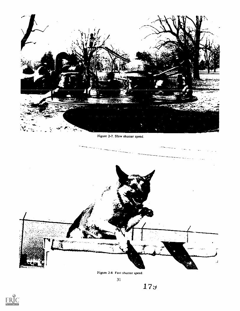
Nie
- ,
...: r.i. , e ,_.3 f^ --- -1'--
'443* 44.r. or
Figure 2-7. Slow shutter speed.
-v
-
4,01, ohm,
Figure 2-8. Fast shutter speed.
31
17
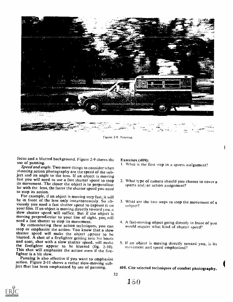
A
1102
7...
-
II-5. 54.0 '
%
UV
4t.
-
4r,4"1-5,A
_
00- 5 44.4
.011
Figure 2-9. Panning.
focus and a blurred background. Figure 2-9 shows the Exercises (409):use of panning. 1. What is the first step in a sports assignment?Speed and angle. Two more things to consider when
shooting action photography are the speed of the sub-ject and its angle to the lens. If an object is movingfast you will need to use a fast shutter speed to stop 2. What type of camera should you choose to cover aits movement. The closer the object is to perpendicu- sports and/ or action assignment?lar with the lens, the faster the shutter speed you needto stop its action.
For example, if an object is moving very fast, it willbe in front of the lens only instantaneously. So ob- 3. What are the two ways to stop the movement of aviously you need a fast shutter speed to capture it on subject?your film. If an object is moving directly toward you, aslow shutter speed will suffice. But if the object ismoving perpendicular to your line of sight, you, willneed a fast shutter to stop its movement. 4. A fast-moving object going directly in front of youBy remembering these action techniques, you can would require what kind of shutter speed?stop or emphasize the action. You know that a slowshutter speed will make the object appear to heblurred. A shot of a firefighter getting into his bootsand coat, shot with a slow shutter speed, will make 5. If an object is moving directly toward you, is itsthe firefighter appear to be blurred (fig. 2-10). movement and speed emphasized?This shot will emphasize the action even if the fire-fighter is a bit slow.
Panning is also effective if you want to emphasizeaction. Figure 2-11 shows a rather slow-moving sub-ject that has been emphasized by use of panning. 410. Cite selected techniques of combat photography.
32
160
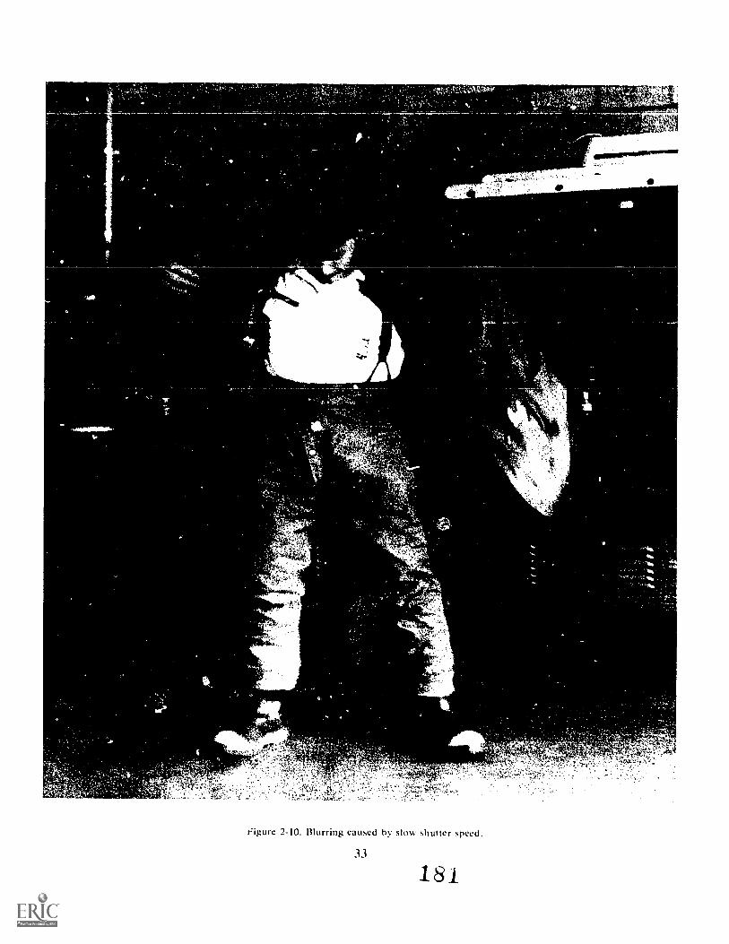
f ,
24.
it
4411
..
, , ''',,''';'::,tiz.;::":,Aet:i
e ..,,i1,,,^ ---4!....Vorkki-,,..--' .. ',",..v41,.: e,.... .4.' . 4.,'...{,^` , , r, ..,, ri j.,,,, ..,r,, 2, 3:,,,,v,i,, , 0.1.4,..,..
1 ,';'-",", --,--- , 1-. .,.-: :',""..i-,,".,"
Figure 2-10. Blurring caused by slow shutter speed.
33
181
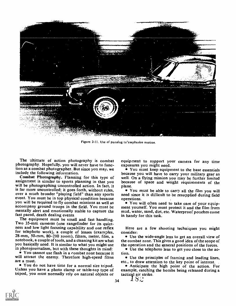
rat._
*it4.,144LVS4A',
Figure 2-11. Use of panning to-emphasize motion.
The ultimate of action photography is combatphotography. Hopefully, you will never have to func-tion as a combat photographer. But since you may, weinclude the following information.
Combat Photography. Planning for this type ofassignment is similar to sports planning in that youwill be photographing uncontrolled action. In fact, itis far more uncontrolled; it goes forth, without rules,over a much broader "playing field" than any sportsevent. You must be in top physical condition becauseyou will be required to fly combat missions as well asaccompany ground troops in the field. You must bementally alert and emotionally stable to capture thefast paced, death dealing events
The equipment must be small and fast handling.Two 35-mm cameras (one rangefinder for its quiet-ness and low light focusing capability and one reflexfor telephoto work), a couple of lenses (examples,28-mm, 50-mm, 80-210 zoom), filters, meter, film, anotebook, a couple of tools, and a cleaning kit are whatyou basically need. It is similar to what you might usein photojournalism, but with these thoughts in mind:
You cannot use flash in a rombat zone because itwill attract the enemy. Therefore high-speed filmsare a must.
You do not have time for a normal size tripod.Unless you have a photo clamp or table-top type oftripod, you must normally rely on natural objects or
4
equipment to support your camera for any timeexposures you might need.
You must keep equipment to the base essentialsbecause you will have to carry your military gear aswell. On a flying mission you may be further limitedbecause of space and weight requirements of theplane.
You must be able to carry all the film you willneed since it is difficult to be resupplied during fieldoperations.
You will often need to take care of your equip-ment yourself. You must protect it and the film frommud, water, sand, dirt, etc. Waterproof pouches comein handy for this task.
Here are a few shooting techniques you mightconsider:
Use the wide-angle lens to get an overall view ofthe combat zone. This gives a good idea of the scope ofthe operation and the general positions of the forces.
Use the telephoto lens to get you close to the ac-tion.
Use the principles of framing and leading lines,etc., to draw attention to the key point of interest.
Anticipate the high point of the action. Forexample, catching the bombs being released during atactical air strike.
34 Si.s
Action at night can create dramatic silhouettes.Also, a nighttime exposure of the battle can give trulyinteresting results.
Portraits of the soldiers and airmen involved arethe most telling of all pictures. Such views show thetension, grief, pride, and the gut determination of ourforces.
Exercise (410):I. Complete the following statements on combat
photography:a. Combat photography covers action which is far
more than sports.b. You cannot use in a combat zone
because it is likely to attract the enemy.c. Normally, you must carry all the
you will need because of limited resupply.d. Wide-angle lenses are used to give an
view of the action,c.
usually are the most telling of allcombat pictures.
411. Specify selected techniques of group actionphotography.
So far in our discussion we have limited the subjectto a singular object. But suppose you have more thanone person or object in the scene. What other con-siderations do you have to deal with? These consider-ations are lumped into a part of your job we will callgroup action photography.
Group Action. We are still concerned with theaction or movement of the subject(s). You must stillapply the action handling techniques previouslycovered; also, you may have to improvise some ac-tion. New problems in group action photography arethe group, what to do with it, and how to show itsaction.
Your first consideration is the size of the group youare trying to photograith. Obviously, a group of 3 or4 people will be easier to deal with than a group of126 people.
If you need a simple group shot, say of a top-flightsquadron, make sure everyone's face is visible. Thesimple way to do this is to arrange the group and thenask if everyone can see the camera. If they can seethe camera, then the camera can see them, and all ofthe faces will be recognizable.
Another problem with a large group is squintingeyes. Indoor shots are no major problem. Outdoorsthough, you need to be aware of the angle of the sun.Don't position the group facing into the sun.
Photographs of large groups are very static. That is,it is hard to show a squadron in action. Therefore,
they arc the exception to the "make sure everyonC isdoing something," rule. Which brings us back to smallgroups.
If at all possible, limit your group action shots to asfew people as necessary to tell the story. In your smallgroup, make sure everyone is doing something. Don'tlet one person adjust a dial while the other people inthe group are standing around with nothing to do. Inother words, don't let your pictures become static.Show some action is taking place, even if you have toimprovise a little.
The easy group action pictures are the ones wherethe group is actually busy doing something. In theseyou won't have to improvise; the group is already busy.For example, an alert crew running to the crew truckactually shows action. However, the same crew wait-,ing in the dayroom does not show much action. So tokeep from having a static shot, you may have to im-provise some action.
The main factor in group action is to show the groupin action. Remember, don't let your photos becomestatic; make sure everyone k doing something.
Exercise (411):I . Complete the following statements by filling in the
proper word or phrase:a. In group action photography you may have to
the action.b. Your first consideration in group action photog-
raphy is the of thec. If all the people in a group can see the
then the can see them.d. Limit your group shots to
people as necessary to tell the
e. Your main concern in group action photographyis to show the group in
2-4. Spot NewsSpot news is not a picture of your dog pouring over
the daily paper. Spot news is events that are happen-ing and must be covered immediately. The discussionson photojournalism and action need to be rememberedduring this discussion, too.
412. Define "spot news" and tell how you can prepareto cover it.
Spot news coverage can be summed up in one wordURGENCY. You must arrive on the scene, get thecoverage, and return to the lab to process and printyour photos. All of this must be done in time to meetthe deadline, sometimes in a matter of minutes.
Spot news events are those events that happenright now. An arriving dignitary, an airplane acci-dent, or weather damage to your base are all spot newsevents. If you didn't get the shots during the event,
35-1 j
you'll have a tough time getting your memoriespublished in the paper. If you did get some shots, buttoo late, you didn't get news--you got history.
In addition to being on time, spot news photo-graphs must have impactboth visual and emotional.They must tell a story that is complete and to thepoint. They do not have to be tear-jerkers. hey canbe humorous or informative. Whatever mood yourpictures portray, it is only temporary. But you mustcapture the mood and get it to the audience imme-diately. If it's not out immediately, it isn't news.
Spot news assignments require that you give yourbest effort and ingenuity. It is, "Get your cameraNOW!" not, "Just a second, Sarge." You will not havetime for researching, planning, organizing, and titne-consuming preparation. Furthermore, spot news eventsare uncontrolled action situations, and your successdepends on your ingenuity and awareness.
About the only preparation you can do is to beready. Have your camera in top operating conditionsat all times. You must get to the scene nownot afteryou have checked out your camera.
When you get to the scene, start shooting. Whileyou are there, be aware of what is happening aroundyou. Visual awareness will let you get !he shot thatmakes the story. Be ready for it.
Your personal preparation may also help you inspot news assignments. You should be able to com-pute exposures, distances, angles, and positions almostautomatically. While you are fumbling with an equiv-alent exposure, your counterpart is winning thePulitzer Prize.
You will probably be on your own at the scene.Therefore, you are responsible for getting the shots.Keep your viewers in mind. They will see only whatyour pictures show them. So show them what hap-pened.
When you have covered the news, get back to thelab, process the film, and print your best shots. Thenrelax because you have just covered a :pot newsassignment.
Exercises (412):I. What is spot news?
2. How can you prepare to cover a spot news event?
2-5. Awards and PresentationsEvery day someone in the Air Force gets an award.
Since that person is proud, he will probably want apicture of the award ceremony. Since you are a pho-tographer, you will have to produce the picture. Andsince you are a professional, you will want to do yourbest work. In this section, we give you some hints and
36
techniques that \vill help volt l oduce your bestpossible work.
As we said before, photography is an art form.Hien:fore, there arc not too many stuict rules tor youto follow. ln this section, we cover the guidelines thatare known to produce acceptable products.
413. Cite selected techniques and principles for pro-ducing awards and presentation-type photographs.
There are four common awards and presentationceremonies that take place in the Air Force. These aremedal awards, trophies and certificates, promotions,and swearing in ceremonies. Except for swearing in,thcy all have certain things in connnon. That is, therecipient, the presenter, and the award. You need toknow how to handle each ceremony and the partici-pants.
Medal Awards. In the award of a medal, there arethree elements involved. The order of importanc. is:( I) the recipient, (2) the medal, and (3) the presenter.
The medal will he pinned on the recipient's leftpocket or breast. Therefore, you should shoot fromthat side. You may find it necessary to shoot from anangle that eliminates one of the participants. If this isthe ease, eliminate the presenter. You may want toshoot the presenter in profile. The point is, be sureyou show the recipient.
Sometimes yOu may stage the presentation. Thiswill help you a great deal because during the actualceremony, things sometimes happen very quickly.Also, some of the rresenters have very little "camerasense." Don't let t!9e presenter's hands hide the medal.
Figure 2-12 shows a typical award ceremony photo-gic4ph. If you have an opportunity to improve on this,do so. You may shoot one standard sh it and then useone of your own creative shots. Remember thatphotography is art, not nuts and bolt:9; so don't beafraid to improvise.
Trophies and Certificates. Sports trophies, certifi-cates of achievement, letters of appreciation, etc., fallinto this category. The standard shot (fig. 2-! 3) showsthe presenter and the recipient holding the trwhy orcertificate while shaking hands below it. Have themhold the certificate or tropl-y so that it can be seen.''lace the participants close to each other. A normalconversation distance leave- too much dead spacebetween then:.
Here, as in medal awar.. oil need to observe thebackground. It should b; as dlain as possible. A clut-tered backgiound will dir,tr:t the viewers' attention.
Have the participants took at the award or eachother. Don't let them "mug" the camera.
Again, you may have an idea to improve tf:is stand-ard shot. Don't be afraid to use
Promotions. The pose for this shot is usually withthe recipient standing beside the supervisor or com-mander. The commander or supervisor is holding the
184

Figure 2-12. An award ceremony.
4.6
Figure 2-13. Standard certificate photo
37
185
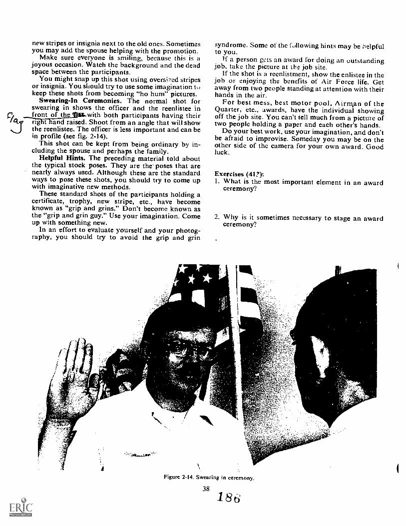
new stripes or insignia next to the old ones. Sometimesyou may add the spouse helping with the promotion.
Make sure everyone is smiling, because this is ajoyous occasion. Watch the background and the deadspace between the participants.
You might snap up this shot using oversi7ed stripesor insignia. You should try to use some imagination tokeep these shots from becoming "ho hum" pictures.
Swearing-In Ceremonies. The normal shot forswearing in shows the officer and the reenlistee in
CI front of the with both participants having theirrig t and raised. Shoot from an angle that will showthe reenlistee. The officer is less important and can bein profile (see fig. 2-14).
This shot can be kept from being ordinary by in-cluding the spouse and perhaps the family.
Helpful Hints. The preceding material told aboutthe typical stock poses. They are the- poses that arenearly always used. Although these are the standardways to pose these shots, you should try to come upwith imaginative new methods.
These standard shots of the participants holding acertificate, trophy, new stripe, etc., have becomeknown as "grip and grins." Don't become known asthe "grip and grin guy." Use your imagination. Comeup with something new.
In an effort to evaluate yourself and your photog-raphy, you should try to avoid the grip and grin
syndrome. Some of the following hints may be Oelpfulto you.
If a person gcts an award for doing an outstandingjob, take thc picture at ihc job site.
If the shot is a reenlistment, show the enlistee in thejob or enjoying the benefits of Air Force life. Getaway from two people standing at attention with theirhands in the air.
For best mess, best motor pool, Airman of theQuarter, etc., awards, have the individual showingoff the job site. You can't tell much from a picture oftwo people holding a paper and each other's hands.
Do your best work, use your imagination, and don'tbe afraid to improvise. Someday you may be on theother sidc of the camera for your own award. Goodluck.
Exercises (41?):I. What is the most important element in an award
ceremony?
2. Why is it sometimes necessary to stage an awardceremony'?
Figure 2-14. Swearing in ceremony.
38
l 8
3. How should you position a certificate or trophy?
4. What type of background should you try to have inany awards ceremony?
5. What is one "trick" you might use to snap up apromotion shot?
6. Who is the most important person in a reenlistmentphotograph?
7. Give an example of what you could to to snap upan awards and presentation photograph.
2-6. Close-Up PhotographyClose-up photography (sometimes called macro-
photography) is not a type of subject, but a techniqueto make large images on film by getting close to thesubject. There is no rigid rule as to what constitutes aclose-up, but methods that achieve at least a 1:1 orlarger image certainly qualify. These image sizes areachieved through the use of special lenses, lens at-tachments, bellows, extension tubes, and even micro-scopes. (When microscopes are used it is calledmicrophotographyand often requires specializedtechniques.) Close-up photography has wide applica-tion in industrial and Tcrtg.ctisiax:toripretport photog-raphy. Th&4-trim4 2)..e le len ez5
keforl- C Z) ft)
414. Cite selected techniques and procedures used inclose-up photography.
There are a number of techniques and types ofequipment that can make close-up photography avaluable tool for you. Let us consider equipment,exposure, and lighting.
Equipment. Close-up photography can be accom-plished with a view camera that has a double bellowsextension. A double bellow extension increases thedistance from the lens to the film to twice the focallength of the lens, thereby producing a 1:1 image. Atriple bellows extension is also possible for evengreater image sizes. The view camera, therefore,would be ideal for most of your close-up work becauseof its large negative size and many adjustments.
The only type of small camera that is really suitablefor close-up work is the reflex type. Through the use ofspecial equipment, cameras like the Nikon F2, can beput to work. Consider the following attachments:
a. A variety of macro lenses are available thatfocus Niery close to the subject and cl-ri give I I repro-duction.
b. Close-up diopter attachments, which are opticalelements that screw into the front of the lens like afilter, give closer than normal focusing capability andthereby permit a larger image.
C. Extension tubes arc rigid tubes that mountbetween the camera body and the lens. Different tubescan be combined to create different effective focallengths. The longer the focal length the larger theimage size.
d. Bellows attachments are available that, like theextension tube, fi between the camera body and thelens. Unlike the extension tube, a bellows permitscontinuous adjustments through its accordian range,and therefore is more versatile.
e. Telephoto lenses can also be selected wherebythe design ("macro" feature) or the use of attachmentspermits you to focus within a couple of feet or less ofthe subject. This permits a greater shooting distancethan shorter focal length lenses while maintaining alarge enough image size. This can be of great advan-tage in nature photography.
f There are a variety of microscope attachmentswhich permit the use of the camera body and micro-scope in combination.
39
NOTE: Close-up photography requires excellentquality lenses. Any type of distortion or defect will bequite apparent with such large image sizes and closefocusing.
Focusing. Sharp focusing is absolutely essential.This is why a reflex camera or a camera with groundglass focusing is a must. A rangefinder camera suffersfrom parallax at close focusing distances. Anotheraspect is depth of field. Due to the short lens-to-subject distance, and Gften long effective focal lengths,depth of field is very limited for any given aperture.Therefore, no focusing error is pernitted.
Film. Choice of film is important. The fine-grain,high-contrast films that can record maximum detailare probably the best choice, but their slow speed cancause problems. Faster films may not have the con-trast or resolving power, but they permit a widerchoice of apertures.
Tripod. The camera must be rigidly suppol tedsince any vibration will result in a soft image.
NOTE: The subject must also be still. If the subjectcannot be held still, such as with a flower or a bird, ahigher shutter speed must be used with a consequentlylarger aperture.
Exposures. Exposure in close-up photography re-quires test and experience unless your camera isequipped with a behind-the-lens light meter. Reflectedreadings are difficult to make because the area beingphotographed is so small. A gray card, however', canbe used as a substitute for the subject. Incident lightreadings often prove easier to take.
However, the basic problem is that the effectivefocal length usually has been changed through the use
1 8 1
ll.:CCSSOFies .!..0 that thC .!, im es ()I;Clis arc not effective. I.or cNampic
lchgth 1/1 throllyb the us,: (It tt / 1.:laticated f, stop become- -fourth iis ei rect it.o. I
means that if the aperture is set at 1: :iciitii 1. feetis as if it were se, at f, 16.
Yoll can \\,ork out the pIoNr expo,,itfc inert:ask:that is necessary if you know the scale of rt. production.Take the scale, add 1 to it, and then square the result.-I-he resulting equation is EF = ( M + 1)2. For example,for a 4 times magnification (4:1), the factor \vould be(4 + = 25. Exposure would therefore have to beincreased 25 times over the exposure reading.
NOTE: A big advantage of those cameras that havebehind-the-lens metering systems is that such an ex-posure calculation as above is unnecessary. The meterwill measure the decreasing amount of light its thebellows is extended or attachments are added.
Lighting. Lighting is essential to good phologcaphyand critical in close-up work. The problem is that verylittle light is being reflected by a subject which issmall. Daylight is normally not bright enough, butyou can increase its effect through surrounding thesubject with reflectors that can increase the overalllighting level on the subject. Most close-up work istherefore done with artificial light like photofloodsand strobes. Such lights become more useful with theattachment of a barn door or snout to direct the light.The best type of light of all is a ring light (circularelectronic flash that fits around the camera lens),which produces very even illumination.
Once you have determined a method to get enoughlight on the subject for a satisfactory exposure, youshould carefully consider lighting direction and ratio.Front lighting with a low lighting ratio is the safestkind and is essential where maximum detail is neces-sary. For more dramatic shots, side lighting (great forshowing textures), cross-lighting, or even backlighting(for examplephotographing a spider web) can giveyou interesting results.
NOTE: Special lighting may be necessary for glass-ware or other highly reflective subjects. Try bouncelighting, use of a diffuser, or light tent. (A light tent isa tent made of translucent material with a hole in it.Lights surround the tent to cast even illumination onthe subject. The camera lens is stuck through the holeto photograph the subject.)
Composition. Composition is as important in close-up photography as in any other type. The large imagesize is helpful in achieving simplicity. You shouldconsider carefully its image placement. The back-ground should be plain and simple. Different coloredposterboards are best for this. Filters can be used toachieve the proper tone or color that is required.
Exercises (414):1. A doubl? bellows extension will prodnee what size
image?
40
citee in cdension tube
,Thp1.1) oi held when doing
4. ou use a ti ipod when doing close-uptt oi±
ruuelt e x posture increase is necessary if you aremai; ii ti X enlargement?
6. Why i a ling light an effective lighting tool?
2-7. Mateciei Ocficiency ReportingIf you bought a tire for your car and later discovered
it had a blemish in it, you would just drive back to th.:.dealer and get it taken care of. But suppose somethingwas wrom.: with the engine that only the factory couldfix. You probably couldn't drive to Detroit to have itehecket] mu. You would send them some pictures ofthe defective part. Then they could tell you how toget your engine fixed.
The Air Force sometimes has the same problems. Apiece of equipment may be defective, but it can't besent back to the manufacturer. So pictures are used.his is where you bcome involved. You are the pho-tographer and will have to take some pictures.
The Air Force calls this a Materiel DeficiencyReport. 'Hu: procedures are covered in TO 00-35D-54, US,11: AIateriel Deficiency Reporting and In-vestigating System.
415. Cite selected photographic procedures andtechnique.: tit:ea la:Aeriel deficiency report photog-raphy.
General Planning. To accomplish good MDRphotography, you will need the proper equipment andmaterials. When planning your equipment list, get asmuch information possible concerning the MDRproject. 1-ind out from the requesting agency whetheror not the equipment to be photographed can be1-irought to the laboratory. This is especially importantwhen small objects are to be photographed, since itallows you a greater choice of equipment, backgroundmaterial, and lighting.
188
If the item is located outdoms, select the ippro-priate equipment and supplies. You should ask your-self the following questions regardless of where thejob is to be done:
a. How much film is needed? What format? Isslow or fast film required? (You will want to use thefinest grain film that you can under the circumstances.)
b. Which type of lighting should be used--availableor artificial? Which will give the best results? (Youwill want as even lighting as possible.)
c. Is it necessary that I take along a tripod'? (Atripod us usually essential to insure steadiness.)
d. Is the subject bright or dark? Is it highly re-flective? Is texture important? These factors willaffect the choice or the direction of your lighting.
Camera Choice. Always use a camera having thelargest possible format that you can. This will insurethe best possible enlargements. The 4 x 5 view camerais probably best suited for the majority of MDR work.This is particularly true because adjustments forperspective may be required. Where a view camera isnot possible, then a press camera would be the nextchoice. The 35-mm cameras are rarely suitable forthis type of work because of the small negative that isproduced.
NOTE: A copy camera is often suitable where theobject is small and therefore can be brought to the laband mounted on the copyboard. For example, a copycamera is ideal to shoot circuit boards.
Lenses. You should have a variety of lenses avail-able so that you can get the necessary image size forthe shooting distance. You should also think about thenecessity for both overall and close-up shots.
Preparation of the Defective Equipment. You mayneed extensive assistance from technicians familiarwith the malfunctioning or deficient equipment.Because of the time required for preparation of thedefective item for MDR photographs, you should beready to perform your mission.
It is often advisable to include a piece of chalk anda black grease pencil with your equipment. The chalkis useful in making cracks stand out on a black surface;likewise, a black grease pencil may be helpful inmaking a crack stand out on a light surface. Commonputty or talcum powder can be used to tone down thegloss on highly polished surfaces. If the photograph isto be taken outside the laboratory, try to foreseeproblems that may occur. A little foresight mayeliminate the need for returning to the lab foirelatively insignificant item of equipment.
Lighting. Whenever possible, avoid using single-lamp lighting. It tends to give high-contrast photo-graphs that lack adequate detail in the shadows.Normally, you get the best lighting by using two ormore floods. You will find that lighting the subject isthe key to top results. The lighting must be even sothat there is full detail. This may provide quite a chal-lenge in location shooting where the defective partmay be in quite a "dingy" spot.
41
Adequate Coverage. 10 instnc .icieinalc phgraphic coverage of thc dc!cc:r.s.closely with the technicians who noriwilly tKeequipment. Niake several photot:r.lphs.photograph from sufficiem dktanc,. to ..(licaicthe item is. Then move in toward the dcfce'., showingenough of the surrounding parts of the sul-ject so thatthose viewing the photograph can tell immediatelywhere the defective part is located with respcct to thetotal equipment. Finally, take at least onc close-up ofthe actual defect, showing the p oblem Irca in detail.Change camera angles as necessary to portray thedefective component and the specific defect clearly.It is better to take too many shots than mq provideenough coverage. (Sec figs. 2-15 through 2-17 fortypical MDR coverage.)
Pilparation of the Submission Photographs. Animproperly prepared photograph is of little value tothe person who must investigate the unsatisfactoryreport. The following paragraph, quoted from TO00-35D--54, is noteworthy.
Each photograph will be marked on the lce with identif yingand orienting hnes, such as aircraft, missile or space ve-hicle. 'VMS and serial number, and sultion numbers andlocations so that the exact location and nature of the re-ported condition is clearly shown. When possible, thesemarkings will be placed on the affected part or adjacentstructure prior to photographing .
Remember, the main reason for forwarding photo-graphs is to avoid shipping the actual equipment.Since the equipment is not available to the investiga-tors, the photographs must be just as good as hayingthe actual equipment. Clarity of detail is essential;coverage must be complete.
Photograph size considerations. There are no speci-fications as to the exact size for the MDR photograph.A good rule to follow is to keep the size as small aspossible, yet show the necessary detail and informa-tion.
Since the transmission of the photographsthrough the mail, the preferred size is 8 by 10 inches(20 x 25cm) or less; but if it is necessary to submitlarger photographs, they should be protected againstdamage. Sheets of cardboard or mailing tubes aregenerally sufficient protection.
Print and negative quantities. We quote TO 00-35D-54 again to learn the number of prints to bemade: "Three prints of each photograph or oneduplicate negative will be forwarded . . ."
Exercises (415):1. What is the advantage of bringing the defective
material to the laboratory'?
2. What speed of film should you use?
181
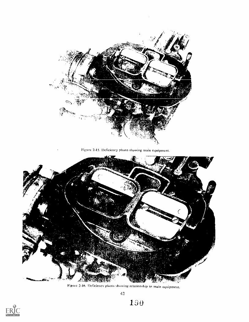
fsa"
r
11E`t,r
/ I
"P"it-%
Figure 2-15. Deficiency photo showing main equipment.
tot
Tt-*,4 ,±0
Figure 2-16. Deficiency photo showing relationship to main equipment.
1 0
_.taigOakal.vtiq4,4t'
,,P
it
Figure 2-17.
3. What type of camera is ideal for photogcni,hirutcircuit board?
4. How might you use chalk when you are shootMDR?
5. What type of lighting is tzLnerally needed in [vii)Rphotography?
6. What TO should you consult to guide you in :AmyMDR work?
2-8. Architectural PhotographyThe daily routinc of photogi.aphing many cotill.101i.
place subjects can become a methodical and un-interesting task. In the process of making pieturc.."just for the record" and frequently shooting the samescene week after weck, you may acquire the habit of
43
iii 11.iii
the lyt:Oc elements of good compositionty the camera. Actually, among the com-
1:lonolact. ntthiet:t.. all around us, there are many:.;:,11e.%: that maLe jul eft sting plmtographs if we take
jiC to Compose them carefully.Wt!en photographing construction work or a build-
iu being remoc:elcd, thea-e is no particular interest inioading to the subject or billowy clouds
in the ltacL-ound. The proper balance of tones andobjcets is of se;:ondary importance. As an Air ForceHn)1(Q..,1-:iph,..r. you .1re concerned with the purpose of
ui.c. that is. you strive to record all of the es-scatial clearly and accurately as possible,
ion or e%aggeration.in i 111'. 10:1, 01 cover some of the techniques
ochitytural photography.
116. ( nrineidfts, ';:c.:;niques, and proceduresarchitectural photography.
"LI ,1,0 do 1,cttc1 job on any assign-lid, it heforehand and make
rations a..:eordingly. Determine;i wl type of camera, the
the time of day, and lightlec photographing the subject.
how much better a subject
BEST COPY AVAILABLE19i
appcars when photographed with the proper lighting.Then, if you pay attention to the faLaors of good com-position, it is relatively easy to produce good, interest-ing pictures.
Film. Use a film with a moderately fast emulsionforthis type of assignment. Because architectural subjectsOften contain many different CM) t,;::t :ireas, the use ofa high-contrast emulsion is not recommended. On theother hand, as textures must be photographed with agreat deal of clarity and good tonal separation, thevery soft portrait-type films may not produce thedesired results.
Cameras. To photograph thc wide variety of archi-tectural subjects, you need a camera that is portableand that can bc used both indoors and in the field. Itshould have a long bellows extension, vertical andhorizontal swing adjustments on the back, front move-ments of tilt, rising front, and lateral shift; and itshould be equipped with both long and short focallength lenses. Since the view camera contains all ofthese features, it is probably the most suitable camerafor this type of work.
Filters. In black-and-white photography do notoverlook the use of filters to change the lighting at anygiven time of day. True, you cannot alter the lightingradically through the use of filters, but often you canmake worthwhile improvements. In photographingarchitectural exteriors, the blue sky is usually thebackground. By selecting the proper filter, you canmake the sky lighter or darker than it usually is whenpanchromatic film is used without a filter.
Outdoor Lighting. From a basic lighting standpoint,photographing the exterior of a building is similar tomaking a portrait indoors. in both cases, the mainillumination must fall on the most important plane ofthe subject, its face.
For general architectural photography, there is astandard approach to lighting of buildings that isusually satisfactory. he first thing to do is to selectyour location. A word of warning: always shoot abuilding so that you include part of one of its sides toshow thc depth of the building. In a head-on shot thebuilding might consist of a single flat wall of bricks, orblocks, as far as anyone could tell from the picture.
Basically, there are two types of lighting that youshould avoid in architectural exterior work. One is thetotally flat lighting you get on an overcast day. Theother is sunlight that comes from directly behind you.Direct sunlighting is flat only if it comes from thewrong direction, such as from behind you.
The best time of day to take each picture isprobably different for every building. Also, differentparts of the same building exterior are best photo-graphed at different times of the day. If the lightingis not exactly right the first time you see the buildingto be photographed, don't be surprised; it usually isnot. If there is no hurry about taking the picture, thething to do is to observe very carefully the lightingeffects at various times during the day. Once you havefound the best lighting for a particular building, therest is easy.
Interior Lighting. Quite often, you can make photo-graphs of interiors using the normal lighting withinthe area. Many interior areas are well enough illumi-nated to produce high-quality photographs when youuse relatively short exposures. Bin under existinglight conditions, a tripod is usually necessary. Therearc times when you need to use floodlights, either tosupplement the interior lighting or to provide the totallighting for the area.
Flash can be used for illuminating interiors, but youwill find that to get high-quality flash illumination,you need considerable skill, especially when shootinga very large interior. Occasionally, when the interior iswell-constructed and painted, bounce-light from aflash source can be used. Instead of directing light atthe arca being photographed, it is directed at theceiling or at the wall behind the camera. When you usebounce-light, you will find it much easier to producean even, overall illumination. It should be noted herethat if difficulty is encountered in obtaining an evenillumination, the bounce-light technique can also beused along with other types of illumination, such asfloodlights.
Under certain conditions, interiors can be photo-graphed very well by the "painting" technique.
When photographing an interior, always be sure toobserve the liening effects created by windows and/or doors that open to the outside. For the best balance,light coming in from the outside must be equal to orless than the light inside of the room. If you neglect tocheck this, you may find that doors and windowsproduce so much exposure in their respective areas ofthe negative that it is iinpossible to obtain a satisfac-tory print. Regardless of the corrective techniquesused in printing the negative, these overexposed areaswill print too light. When it is impossible to overcomebrilliant exterior lighting conditions, you may needto make the interior photograph at night.
Painting with light. The technique called paintingwith light is essential to every photographer. As theterm implies, light is painted on the subject by movingthe lamp continually over every area of the scene.This is done throughout the duration of a very longexposure. Since light is painted over the subject whilethe exposure is being made, painting is suitable onlywhen exposures are long.
To use the painting technique, open the shutter,move the light over the subject until you obtain thedesired total illumination, and then close the shutter.The intensity of the lamp in any given position duringthe painting procedure is controlled by the lamp-to-subject distance. By moving close to the subject, thearea illuminated can be lightened in the print: bymoving away, it can be darkened.
Many times, the painting technique (just as is thebounce-light technique) is used in combination withother lighting. In this way, you c: extra ex-posure to any special portion c _:notograph.Painting with light is especially .. till when youmust photograph a large object or a large area. Also,when details within the shadoW areas are important,
44 192
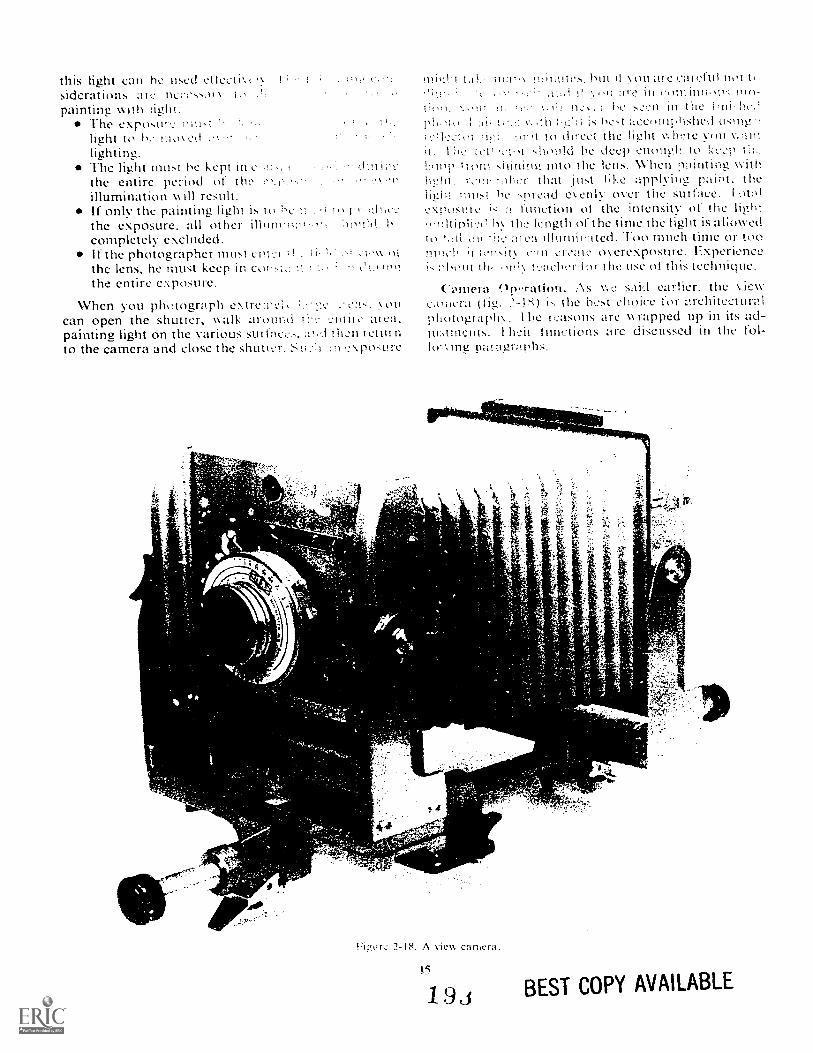
this light can he used etlecti',siderations IlCcc.),painting with light:
The exposurylight to hc 1110\ t,
The .g.it must he kept in ,the entire period of theillumination will result.If only the painting light is tothe exposure, all other :louhtcompletely excluded.If the photographer must cotyl ; 01
the lens, he must keep in cov,..:,,Athe entire exposure,
When you photograph extren,can open the shutter, walk arourAl -entite area.painting light on the various sutfac,....-...;t!,d tlin returnto the camera and close the shutter. pot:u
.
±Ai'ef . .1;
s
l,11. \ hilt V011 are careful notare in
V. : SCt.'11 ill thepl!,)io. | Al, Hirt ilct 4ccomplished using '!
it to drcet the light whcre vou V.1.101it. I hi.2 Mould he deep enough. to
trom shining into the lens. \Viten ptrintMg with¶-,?!1, iiihcr that just like applying painc the
must he spread eenlv over the sutface.exposule function ot the intensity of the light
h th:_. length of the time the light is aliowedto L,i1 ,ut thy u illuminited. oo much time or toomuch I t,"nsit\ c!in cr,.'ate overexposure. Experienceic.:"hout lor the use of this technique.
Camera 9n-ration. As we said earlier. the viewc,oilurti (fig. .'.-1"0 i. the hcst choice for L'.rehitecturalpliotograph. Ihe reasons are \\ rapped up in its ad-ju:.ttnclits. I hen functions are discussed in the
ptiragmphs.
4
44 e"4..4
2-18. A view camera.
I5
19j
4:
BEST COPY AVAILABLE
Iti.sin from. lite risMg trout atim.s tile tens to beraised in I Llation to the center ot the negative, thusextendinc the effectk c angle of vicw in a verticaldirection. It permits brinizine more of the beight ofthe object into the field without fear of distortion ob-tained when the camera is merely tilted upward. Thisadjustment is limited by the physical construction ofthe camera and the covering ability of the lens.
Falling front. The falling front permits the loweringof the lens in relation to the center of the negative.The function and principle of operation are similar tothose of the rising front.
Slidingfront. The sliding front allows the horizontaldisplacement of the lens in relation to the center of thenegative. Its principles of operation and function aresimilar to those of the rising and falling fronts.
Vertical swing front. This view camera control isused the change the plane of focus of the lens whenphotographing tall objects. This is necessary becausethe distance from the top of a tall object, such as abuilding, to the camera is obviously greater than thedistance from the bottom of the object to the camera.Tilting the camera lens to its axis does not alterimage shape on the groundglass; only image focus ischanged. The vertical swing front is most often usedin conjunction with the vertical swing back.
HorLonlal swing front. This control serves the samefunction as the vertical swing front, except that it isused on the horizontal plane such as when photo-graphing long objects at an oblique angle. It is mostoften used in conjunction with the horizontal swingback. When using either the vertical or horizontalswing front, you should remember that these adjust-ments are limited by the usable circle of illuminationof the lens.
Vertical swing back. This is perhaps the mostimportant adjustment and the one used most inarchitectural photography. It is employed to preserveparallel relationship of the camera back to the subjectplane, and sometimes to compensate for focal dif-ferences of the subject plane (without consideringparallelism). If a subject is too tall to be included inthe field of view, even when the rising front is used,the camera is tilted upward and the camera backswung into vertical position, parallel with the subject.There is a discrepancy of focus, as the lens axis isstill parallel with the camera bed, but this may be com-pensated for by stopping down or tilting the lens.
Horizontal swing back. This adjustment is identicalin action with the vertical swing back, except that itcontrols horizontal parallelism or horizontal focaldifferences. Its use in architectural work is largelyconfined to correcting exaggerated perspective whenthe camera is turned at an angle to the subject. Whenthe sliding front is insufficient and the camera must beturned to the right or left to include a greater area ofthe subject, the horizontal swing back retains theparallel horizontal relationships. Of course, hori-zontal perspective is not as troublesome as verticalperspective. In cases where angular views of buildingsare concerned, no horizontal linear corrections are
46
required. In such cases, the horizontal swing backis most useful in compensating focal differences.
Back focusing. On most standard view cameras,both the front and back assemblies are movable onthe camera bed, and focusing may be done witheither of them. In working close, the back focusing ismost helpful, since image size may be controlled bycarefully setting the distance of the camera back fromthe subject, then correcting the focus with the frontassembly. If only front focusing is available, the entirecamera must be moved forward or backward tomake small adjustments in the size of the image. Backfocusing gives opportunity for most careful scaling ofthe image.
All camera adjustments have little meaning unlessthe camera is first set up in the ideal positionthat is,level in both vertical and horizontal directions, withthe axis of the lens centered on the film plane andwith all adjustments set at "neutral" and checked foralignment. As the composition is developed on thegroundglass, certain adjustments become necessary.Never make any camera adjustment except when ittruly is required. All deviations from normal in theposition of the lens in relation to the negative de-preciates the quality of the optical image.
Use of the view camera will be less confusing if youremember these three rules:
(1) Rising, falling, and sliding movements are usedto control the position of the image on the film plane.
(2) Vertical tilt and horizontal swing of the cameraback are used to control the shape of the image on thefilm plane.
(3) Vertical and horizontal swing of the camerac'3nt are used to control the focus of the image on thefilm plane.
Exercises (416):I. From the following statements about architectural
photography, identify which ones are true:a. You should use a high-contrast film for all
architectural photography.b. A 35-mm camera is the best camera for archi-
tectural photography.c. Shoot a shot of a building to include two sides.d. You should avoid totally flat lighting.e. Flash illumination can produce acceptable
results for interior lighting.When you shoot inside a house, open all theblinds and doors to give even lighting.When painting with light, you should keep yourlight in constant motion.The front adjustments of a view camera controlthe focus.
f.
g.
h.
2. What are the requirements of a camera to be usedfor architectural photography?
1 9
3. What are the two types of lighting you shouldavoid in exterior architectural photography?
4 What kind of exposures must you use if you are;Loing to paint with light?
5. Cite the three rules of view camera operation.
2-9. Investigative PhotographyInvestigative photography is ju,,t that; it is not an
editorial nor an essay. It must be fac.ual, straight-.forward photography. If done properly, it will be veryvaluable to the investigative agency.
In this section, we include as investigative photog-raphy, aircraft and ground accidents and legal andcriminal types of photography.
417. Specify techniques used for adequate coverage ofaircraft and ground accidents.
Purpose and Scope of Investigative Photography.The objective of crash and accident photography isto provide good quality photographs to help investi-gating personnel determine the cause of the accidentor crash. For example, in the case of vehicle accidents,the photographs may supply vital information byshowing skid marks, point of impact. roadand environment that may indicate the cause of theaccident. Some of the things accident photographscan indicate are:
Carelessness in the operation of a vehicle.Loss of control due to speF:d or a defective mech-anism.Inadequate control due to physical disability ofthe operator, perhaps because of illness, intoxi-cation, or drugs.
These same photographs may also be used as evi-dence in a military court of law.
Photographs of aircraft accidents become anintegral part of the investigation. Such photographsserve a dual purpose. First, they help the investigatorsto graphically reconstruct the events of the crash;second, they provide a means of identification of partsof the aircraft. The distribution of parts in relation tothe crash site and the initial point of impact can helpindicate what happened during the crash.
Often these photographs are shot in color to showthe extent of heat or chemical damage. The use ofcolor also allows the investigating team to determine
other factors not easily recognizable in black-and.-white photographs. For example, suppose that aninternal explosion during flight caused an aircraft tocrash. An analysis of the black-and-white photographsreveals that the explosion was caused by the malfunc-tion of a small moving part in the engine. If color filmwere used, additional facts may be brought to light.For instance, excessive friction on the moving partsleaves a color pattern. A photograph of this part incolor would tell the investigators the degree of wearand the temperature caused by the friction.
Emotional Stability. Crash and accident photog-raphy requires an emotionally stable photographer. Itmay be necessary for him to observe other personssuffering from severe wounds, fractures, burns,mutilation, or shock. Add al', some of the in-juries may -,-)e sufficiently severe to cause death.Conditions as mentioned, plus the confusion andexcitement that normally accompany a severe acci-dent, may cause nausea or even fainting. It is im-portant that the photographer be able to go about hiswork objectively just as he would if he were coveringany other subject. He must not add to the problemalready existing. In addition, he must be able to thinkabout the photographic problems involved. He mustbe calm under the very serious conditions which he.may encounter.
Seeking Assistance. If possible, try to find outbefore you leave exactly to whom you should reportwhen you arrive at the scene. If absolutely necessary,obtain either advice or assistance from the person incharge of the situation. This could be a person repre-senting any of the following career areas: safety, fireprotection, security police, investigations, medical,aircrew protection, or the senior officer at the scene.Whatever you do, do not interfere with personnelperforming essential duties related to the emergency.
Release of Information. Under no conditions do youhave the right to release any informationeitherverbal or photographic- to a iti outside the nor-mal Air Force channels. You must learn that whatyou photograph is the property of the Air Force. Re-lease information only to the proper authorities, ortheir repre.,entatives, who are cnarged by the AirForce with a need-to-know.
Mission Planning. Almost every base photo lab hassomeone available to take crash and accident photo-graphs on a 24-hour, 7-days-a-week basis. This pe -onis known as the "Alert Photographer." Also, almostevery photo lab has a particular camera to be usedspecifically for crash and accident photography and itis usually referred to as an "Alert Camera." If a call isreceived, all that is necessary is for a photographer topick up this equipment and report to the scene.
The alert camera kit should be prepared beforehandand should contain film holders or film packs andadapters, flash equipment and such other material asmay be needed to insure complete coverage of themission. It is important that the camera case be care-fully checked for necessary supplies and equipmentfor proper operation.
47
1 9
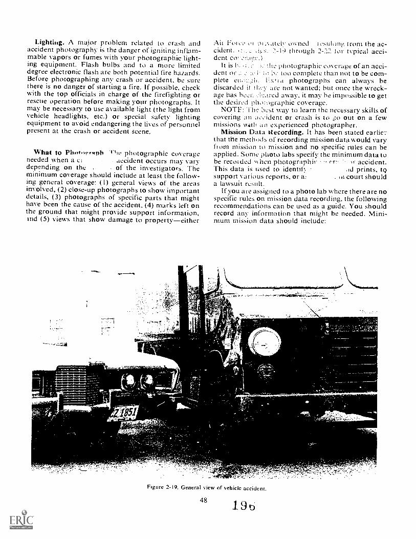
Lighting. A major problem related to crash andaccident photography is the danger of igniting inflam-mable vapors or fumes with your photographic light-ing equipment. Flash bulbs and to a more limiteddegree electronic flash are both potential fire hazards.Before photographing any crash or accident, be surethere is no danger of starting a fire. If possible, checkwith the top officials in charge of the firefighting orrescue operation before making your photographs. Itmay be necessary to use available light (the light fromvehicle headlights, etc.) or special safety lightingequipment to avoid endangering the lives of personnelpresent at the crash or accident scene.
What to Photoph The photographic coverageneeded when a ci . accident occurs may varydepending on the .. of the investigators. Theminimum coverage should include at least the follow-ing general coverage: ( I) general views of the areasinvolved, (2) close-up photographs to show importantdetails, (3) photographs of specific parts that mighthave been the cause of the accident, (4) marks left onthe ground that might provide support information,Ind (5) views that show damage to propertyeither
111PWIR
OVA,
torsi1514.1
El
AU Fore:. or pi :\atelv wyned- Irom the ac-cident. 2-19 through 2-22 for typical acci-dent co,..!ra ge.)
It is h: :he photographic coverage of an acci-dent i i. 11.- too complete than not to be com-plete enc.t,..21,. C.N,ia photographs can always bediscarded it !1:yv are not wanted; hut once the wreck-age has hos.::-....-leared away, it may he impossible to getthe desired photographic coverage.
NOTE: OL-st way to learn the necessary skills ofcovering au Lie,ident or crash is to go out on a fewmissions with an experienced photographer.
Mission Data Recording. It has been stated earlie.:that the methods of recording mission data would varyfrom mission to mission and no specific rules can beapplied. Some photo labs specify the minimum data tobe recorded when photographir cr. 1r accident.This data is used to identit ad prints, t9support various reports, or a: iu court shoulda lawsuit result.
lf you are assigned to a photo lab where there are nospecific rules on mission data recording, the followingrecommendations can be used as a guide. You shouldrecord any information that might be needed. Mini-mum mission data should include:
I
,
Figure 2-19. General view of vehicle accident.
48 190
--..111111111116
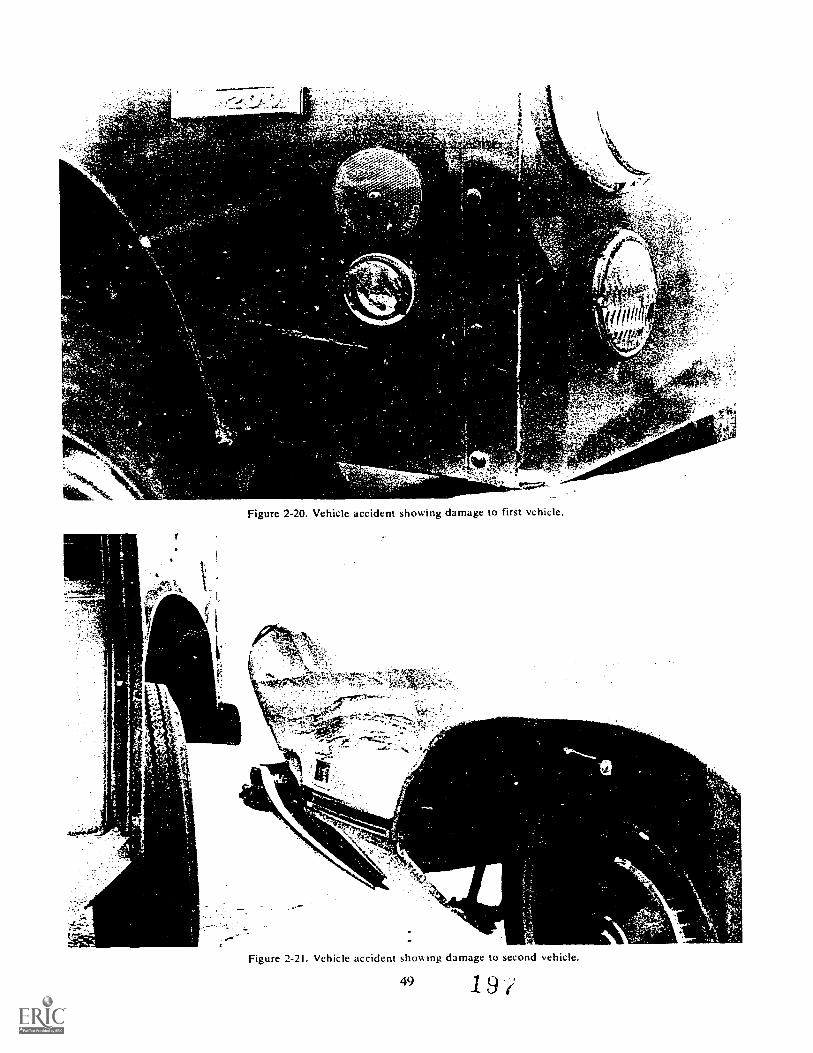
Is
4
Figure 2-20. Vehicle accident showing damage to first vehicle.
Figure 2-21. Vehicle accident showing damage to second vehicle.
49 19/

a.b.C.
d.e.iT
g.h.
3.
a
A
Figure 2-22. View of vehick accident showing road conditions.
Type of film used.Date, time, and location of accident.Classification.Vehicle, aircraft number.Make, model, and year of vehicle.Tag number and state (civilian).Type of lighting used.Weather conditions.Name of individuals involved.Persons with whom you dealt.
Safety. Observe the general, mechanical, electrical,and ground-safety precautions that apply to the type ofequipment you are using and to the area in which you
are working. Some of the major precautions to be ob-served when taking crash and accident pt;otographsare as follows:
a. Stay out of the way of emergency vehicles anddo not become a casualty through carelessness.
b. Don't touch anything. You have no authority tochange any condition. Photograph objects as they are.
c. Exercise necessary precautions when workingin or around flammable substances or conditions.
d. Stay alert and be ready for any unforeseenemergency tl'at may develop while you are takingp hotographs.
e. Be sure that you are aware of the policies rela-tive to photographing items of equipment that areclassified.
f Do not blind the drivers of approaching cars byflashing flash equipment in their direction.
Exercises (417):I. What is the purpose of photographing an accident
or crash?
2. What is the advantage of color coverage of an ac-cident?
3. Why must an alert photographer be emotionally;:"P during an accident?
4. To whom should an alert photographer releasecrash information?
5. What problem is '.hcre in using flash during anaccident?
6. List five areas of general coverage that should betaken at an accident.
7. What type of mission data is recorded in regard toa civilian automobile involved in an accident?
418. Given hypothetical legal/criminal i.hoto situa-tions, determine if the proper techniques were used tophotograph them.
tnotos. Photography is the only/1 med to presc-ve history fact-
-1 there bee: .1 photographerurge Washington crossed the river,
we would know for sure if he really stood up in thatboat.
Photographs are used in legal and criminal investi-gations because they show what is there. They can bebiased but not if you shoot them properly. This sectiondeals with the methods you must use to show the sceneor the evidence honestly and factually.
Uses. There are several ways in which your legal/criminal photos are used. Among the uses are:
51
Evidence. Photos are used to record crime scenes,traffic accidents, hordicides, fires, objects ofevidence, fingerprints, etc.Action of offenders. Photos can be used insurveillance of suspects, burglar traps, to recordconfessions, in re-enactment of a crime, and torecord the testing of a person suspected of beingintoxicated.Court exhibits. In a court, your photos may beused as enlargements, single photos, slides, and asactual evidence.Prevention. Photos are sometimes used in crimeand fire prevention lectures and in safetybriefings.
Procedures. There are certain established pro-cedures you should follow when shooting a legal/criminal assignment. Since there are sc many dif-ferent situations you could get into, we will coveronly those most frequently encountered:
a. Identification. You may be called on to photo-graph a suspect or even the convicted person. If youneed to photograph such a person, do it in a factualmanner. Do not worry about flattering lighting orposing. Show every freckle, mole, or blemish whichmight aid in identifying the subject. A head-and-shoulders composition with front, flat lighting will dothis effectively.
b. Crime scene. In crime scene photography,particularly those of a violent nature, the scene mustbe shown clearly. The location of the scene and theobjects in it are of vital importance. Your first stepshould be to photograph the entire scene. You mustthen get comrlete and accurate photos of all the as-pects of the scene before any objects of evidence areremoved or disturbed (including bodies).
Do not move or touch anything yourself. If thelighting or position of an object is poor, do the bestyou can.
Crime scene photos are supposed to provide viewsof the area as would be seen by an average observer.A set of four photos is the minimum to show a room.Medium and close-up shots should be taken of im-portant items. You will find that a wide angle lens isnearly a must for crime scene photography.
c. Burglary and vandalism. In this type of photog-raphy you are again interested in the scene. Youshould get photos of.
General vi, VsI nt of e Ht.
Articles left at the scene.Marks from tools, shoes, and tires.Areas from which items were removed.
d. Homicide. Your photos here should set the scene,provide information concerning the manner of death,and show if the crime was connected with a burglary.
To help investigators later determine the manner ofdeath and locate the body in relation to the otherarticles in the scene, produce at least two photos of
H

11:. i),dy. 1 hese should be taken at 111.:lit angles tootti,2t . Point the camera litMn trom a normal
poSition. Other photos should include close-ups ,d the wounds. location ot the instrument ot death.and other special aspects ot the body.
[laaging. Photograph the original position ot thebod to help in determining the manner Of death. lake
.)\ icw of the body and rope. Show the heightol thc od ihoe the ground. Show the
of objects. sueh as elmits or stook. whiehappedi ;o have been kicked Out from under the 0i:-tint's
drov,Mngs. the body is usually thesole oht et of interest. Color film is usually helpfulsMee many of the clues mav be matters ot discolora-tiori. tograph the entire body from a standing posi-
a IMMgiound le\ el. Close-ups should includetotun about the mouth, wounds. peculiar loarkings.bruises, or unusual discoloration.
g. Assistance. If you have a problem at the scenebe surc to ask the person in charge for help. Thisp;:rson may be from the safety office. tire prevention,se,21!,it pohce, medical, or the Office of Special
(051). 13e sure you kno.v what you aredoing Lind that \ ou do not interfere v.:th the otherpeople v. Ito are trying to do their jobs.
Exercise (418):1. 1 tom the following examples, determine if the
pho,a rapher acted properly:When called on to photograph a suspe,.,.t.eli Jones rositioned his lighting so that it hid a--ar on the suspect's face.
hilc at the crime scene, Sergeant Smith needed:;hot of a knife which was partially hidden, fie
took as many pictures as he could from differentangles. but he did not move the knife nor any-Hing else.
c. At a scene of a hanging, Airman White tookseveral shots of the entire room. 'Fhen she madesome photos he body Flr',e photos inct '
as tt;.ned
2-10. Operator MaintenanceSo far we have told you how to handle certain shoot-
ing situations. We have made the assumption that allyour equipment was in proper working order. In
section, we will cover operator maintenance. Weci -)rne of the things you can and should do to heurt: yo,s7 equipment will work when you get to your
mission are:t.
419. Cite principks and requirements of cameraoperator maintenance.
General Principles. Give all items of photographicequipment an operational check prior to using them.Some items that fall into this eateogry are camerabodies. shutters, film holders, tripods. Hash equip-ment. rangef inders. timers, processing equipment,lenses. and diaphragms. In the course of a single yearyour camer..s and accessories may be exposed to theextremes of the elements such as snow, rain, heat,cold, and humidity. Exposure to the elements can be
ploblem. Unless protected. mechanical parts getrusty, bellows mildew, leather dries out, lens elementsseparate, and gear trains wear out, to name a fewpi oblems.
Modern cameras are masterpieces of electrical,mechanical, and optical engineering. With proper careand periodic maintenance they will give years oftrouble-free service. Many times the condition of theequipment and tools that people use in performingtheir daily tasks can tell a lot about the quality of workthat they perform. A person who keeps his equipmentclean and neat gives the indication that he caresabout his work. For example, if you needed to haveyour car repaired, you would probably be more trust-ing of- the mechanic who keeps his tools in top condi-tion and neatly arranged on his workbench. Most of uswould be suspicious of the person who has set up shopunder a shade tree and stores his tools on the ground.A mechanic's tools can be compared with the equip-ment that you use in photography; cameras, tripods,flash units, etc. Each of these items are the tools thatyou must depend on every day to get the work done.The mechanic who doesn't maintain his tools properlyis liable to break a knuckle or twist off a bolt. Like-wise, if your camera fails to work when you need it,you have blown the assignment.
Maintaining Your Camera. Cameras are the mostbasic tools of photography. A camera is a relativelydelicate instrument and must not be subjected torough handling and abuse. Dropping a camera usuallyresults in extensive damage, often rendering thecamera unusable. Always carry Your camera in sucha way that they cannot he accident:: dropped.M(-1 35 a". -iec ..ameras are
i; heck i he condition ofst lien to insure that they will still support
the weq_ the camera.Whenever a camera is not in actual use, the lens
should be covered with a lenscap and the cameraprotected in a ready case or carrying case.
Protection from heat. Never submit any camera toexcessive heat. An example would be leaving a camerainside a locked automobile on a sunny day. Darkcamera cases of brown or black leather, although, verystylish and therefore popular, present problems ifleft sitting in sunlight. When on an assignment, makesure that you do not leave your camera case exposed todirect sunlight for prolonged periods of time.
Excess;ve heat does nasty things to photographicequipment and film. High heat w ill tog your film. Alens left unco :led in direct sunlight can locus thesun's rays on the local plane shutter of a camera andin some cametas -actually burn a hole in the shutter.Excessive heat can ako cause lens _,Huents to sep-arate.
Humuthy. A humid environment takes a hex tollon photographic equipment. It can (..9.He for togrow between lens elemen4 ., lir ua-tion of mildew which , ...athei and vinyl sur-faces such as camera bellows, camera bodies, andcases. Of course, metal parts corrode much morereadily in a humid environment. Keeping ahead of theeffects of humidity involves continual cheeks on equip-ment and adequate protection both w hilc in use and instorage.
When cameras are to be stored for long periods oftime, a dehydrating agent such as bags of silica gelshould be packed with the camera. Never seal camerasand lenses in plastic bags because this will only pro-mote corrosion. Plastic bags are nonporus and theyretain moisture.
Occasionally you may have the misfortune of get-ting caught in a rainshower while out on an assign-ment, or you may have to cover an accident in adownpour. Try not to get your camera wet. It is a goodidea to carry a large plastic bag with you. Place thebag over your camera and shoot through a hole madein the bag. There are commercially available plasticcovers which serve the same purpose and are a wiseinvestment in areas that have a lot of rainfall. Im-mediately upon returning from the assignment youshould cat efully remove all moisture from the cameraexterior and then remove the lens and open the cameraback to check the camera interior for moisture. Unlessyou were really careless and got your camora soaked,you probably won't find any moisture within thecamera. Moisture within the camera lequires im-mediate disassembly by a camera terairman. Don'tattempt to tear down a camera Yourself. This is wort<for a qualified repairman.
Cleaningalv .
g aan operational
:neck tographic gear. The camera shouldbe clean -ad a,. controls working properly. Cleaningprocedures are best performed after returning from anassignment because the equipment has been sub-jected to the elements.
The first step in cleaning a camera is to remove alldust and dirt irom the camera body exterior and theexterior of the lens barrel. Use a soft brush and thenpolish metal surfaces with a soft, lint-free cloth toremove smudges.
Camera lenses require special care. rhe surfaces ofmodern lenses are given an antitlar.. coating duringmanufacture. This coating is fairly tough, hut it can bedamaged if the lens is not cleaned properly. Gentlyblow off any ditt and dust on the lens sui face usingyour breath or better yet, use an air syringe. The lenscan then be polished using photo lens tissue. Always
use only photo lens tissue. Never use lens tissue de-signed for cleaning eyeglasses. Eyeglass cleaningtissue usually contains silicones which can damage thecoating of photographic lenses. To polish the lens,grasp a sheet of lens tissue between your thumb andforefinger and polish using a circular motion v.from the center of the lens to its edges, Sonic:
')cri a lens has been neglected, polishing with photolei. issue will not get it clean. Should you have thisproblem you can use photo lens cleaning fluid. Neverapply the fluid directly to the len because it can seeppast the front lens element and cause interior lensdamage. Apply a few drops to a piece of photo lenstissue and then apply it to the lens. The lens ean thenbe polished using a dry piece of lens tissue. Cleaningis the most important part of operator preventivemaintenance.
Other than keeping your cameras clean and pro-tecting them from damage there is little else that youcan or need to do. All photographic equipment shouldbe scheduled for periodic maintenance by qualifiedequipment maintenance personnel. Any minor prob-lems that you have been experiencing with yourequipment should be noted, and this informationshould be given to maintenance personnel at thetime your equipment is turned in for periodic main-tenance. Periodic maintenance is conducted at 60-,90-, 120-, or 180-day intervals, depending upon theparticular type of photographic equipment involved.
Check the operation of your cameras and equip-ment often, especially before and after it is used. Theshutter on any camera should never be left cocked forlong periods of time. When not in use the shuttershould be set at its slowest speed. These actions takethe tension off of shutter springs and mechanisms,thereby extending their life and maintaining theiraccuracy.
Rangefinder cameras. Rangefinder-focusingcameras should be checked periodically to i:they are focusing properly. Th;s is son',v.'w ran check if you are 1.ng a came has
_angefinder and ground-glass focusing .2h as!e Graflex xl. Place the cam: on a tripod and
locus the camera on infinity wit:. ne rangefinder andthen check the focus on thf.! groundglass. Repeatthis procedure on a close object. If the rangefinder isout, it requires immediate attention by a repairman.Don't attempt to make any adjustments yourself.
Cameras with bellows. The flexible bellows used onview and copy cameras should be checked periodicallyfor light leaks. This is especially true if you are ex-periencing film fogging. Take the camera into a light-tight darkroom, remove the lens and back from thecamera, and probe the inside of the bellows with aflashlight.
Mechanical flare. Mechanical flare is often causedby internal reflections from bright surfaces w;f bin thecamera and also near the lens. Check the len .ades,retaining rings, and the camera interior tor placeswhere the black paint has been chipped, exposingbare metal. These spots can be touched up with a flat
53,
black paint. Check with a repairman on the type ofpaint that should be used.
Re] lex Piirrors. The mirror of reflex cameras shouldnot be touched. Blowing dust from its surface with anair syringe shoLld be all that is required.
only when necessary, and you should have no prob-lems.
Exercises (419):I. How should you carry a camera?
Flash Lighting Equipment. Maintaining electronicflash units is relatively simple. Electronic flash units 2. Why must you protect your camera from heat?have a series of capacitors which store electricalenergy at very high voltage. Tripping the strobe causesthis energy to be applied to a flash tube filled with aninert gas. As the current flows through the tube it 3. List two problems that high humidity can cause.causes a very bright but extremely short burst oflight. In order for the unit to operate at maximumefficiency and put out the maximum amount of light,a technique called forming or the rejuvenating the 4. If you got your camera wet, what should you do?capacitors must be done.
Forming the capacitors allows them to take a fullelectrical charge. This is done initially when the unitis first put into use and must be reaccomplished 5. Why shouldn't you use eyeglass tissue to clean aeach time the unit has not been used for a few days. camera lens?Most professional electronic flash units operate onboth household current and batteries. Regular ACcan be used where there is an available outlet, andbatteries can be saved for those occasions when it is 6. How can you repair a camera that shows mechan-not available or not practical. Househo1d current ical flare?should be used when forming the capacitors of theunit. To form the capacitors the unit is connected tothe power source and allowed to take a charge. Theunit is then fired a number of times at a set interval. 7. What is the purpose of forming the capacitor?This procedure may be different for each type offlash unit, so check your instruction manual.
The types of batteries used in electronic flash unitsare either the dry cell or rechargeable (nickel-cad- 8. What protective devices should be used to protectmium) type. Dry cell batteries are probably the most a camera when it is not lrl use?convenient because they are discarded when no longerusable and quickly replaced with fresh batteries.However, dry-cell batteries are exp tisive and therechargeable nickel-cadmium are becoming more 9. At what time(s) should you perform an opera-popular. Nicads offer the same advantages of port- tional check of your camera?ability as dry cells, and because they can be recharged,they are much cheaper in the long run. They must bemaintained properly if they are to give good service.Nicads actually benefit from continuous service, and 10. Why must you never apply lens cleaning fluidthey should be fully discharged before being placed directly to a lens?in a recharger. This improves their ability to take afull charge. Nicads left in storage for extended periodsof time will drain. Nicads lose their ability to take afull charge if they are not fully discharged period- I I. At what speed should you set the shutter if youically. Use your electronic flash unit daily, recharging are storing a camera?
54
Studio Assignments
MOST OF TH E assignments we covered in Chapter 2were of an uncontrolled nature. When you move intothe studio, things become far less hectic. You can havethe camera and lights set up before the subject arrives.After the subject arrives, you can move the lights, thecamera, aiid even the subject. All of this can be doneunder very controlled conditions, and you can tellwhat the final effect will be before you trip the shutter.
Your studio work, like your other work, will im-proye with practice, experience, and counsel fromothers. In this chapter, we will try to start your ex-periences off right with the techniques, principles,and some more helpful hints for you to use in thestudio. We will cover portraits, passport and identifi-cation photos, special assignment photos, and oper-ator maintenance.
3-1. Portrait PhotographyA portrait is not just another photograph. It is a
carefully composed portrayal of a person often usedfor publicity purposes or as a method of identification.(Identification and passport photography will becovered in a later section.) Good portraits do not justhappenthey result from careful application of manydifferent techniques. Above all, good portraits usuallyresult from many years of experimentation and prac-tice. Making good portraits requires both artistic andphotographic ability. Portraiture often involves work-ing with persons of senior rank, children, and membersof the opposite sex. Self-confidence and the abilityto handle people properly are sxtremely important.
420. State the requirements for portrait photography.
Portraits are an important part of any base photolab mission. Portraits are used in personality features,for keyman and chain-of-command displays, and forthe very important A FR 36-93, Official Photographs,requirements. Let us discuss each one of these.
Personality Features. People are interested in otherpeople. On every base there are thousands of ind ivid-ials who are contributing to the Air Force mission.Their individual accomplishments can be spotlighted
55
CHAPTER 3
by a picture story. Such a story would be highlightedby semiformal and informal portraits of the individual.Most of these pictures would be taken at the individ-ual's place of work or when he is taking part in theactivity that has made him stand out.
Groups, too, can be considered. Portraits of thewinning softball team or a group of volunteers whomake monthly visits to a home for the aged are com-mon examples. These portraits are taken on locationand emphasize the group's particular accomplishment.
Keyman Pictures. Each level of command has keypersonnel who hold leadership functions. To spotlighttheir responsibilities, their portraits appear on bulletinboard displays. Such portraits are usually head andshoulder poses taken in the studio. They should bedignified military portraits.
Chain-of-command pictures follow this same prin-ciple. In each headquarters building there is usuallya display of photographs showing a chain of commandstretching from the President to the base commander,etc. Many of these photographs are supplied by higherauthority. The pictures of the local commanders aresimilar to the AFR 36-93 format that will be dis-cussed next.
AFR 36-93. AFk 36-93 requires officers to main-tain official photographs in their personnel records.These photographs are important as they become partof the officer's promotion folder. 1 he updating ofthese pictures is spelled out in the regulation. Asphotographers we are most concerned with the follow-ing specific picture requirements.
Position camera height approximately level with theofficer's eyes. Use a light colored backdrop (white,gray, or light blue), which will assure a neutral back-ground. The pose will be formal, showing head andshoulders with the face directly toward the cameraand the body turned approximately 30° to 45° to theright so the left shoulder is forward to the camera andthe name tag is visible.
Finish the portraits on 8 by 10 inches, black-and-white, single-weight glossy paper with 1/4-inch borderon top and sides, 3/ 4-inch border on the bottom.
Reproduce an identification frisket in the :owerleft corner of each print, I inch from the lower edge,measuring approximately I / 2 by 3 inches on the printsand not covering the name tag or any ribbons orbadges. The frisket will display the officer's last name,
2,
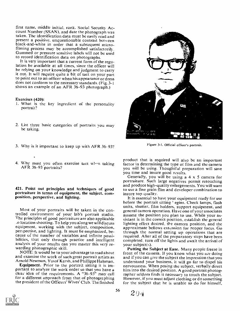
first name, middle initial, rank, Social Securit Ac-count Number (SSAN), and date the photograph wastaken. The identification data must be easily read andpresent a positive, unquestionable contrast betA eenblack-and-white in order that a subsequent micro-filming process may be accomplished satisfactorily.Gummed or pressure sensitive labels will not be usedto record identification data on photographs.
It is very important that a current form of the regu-lation be available at all times, since the officer willbe relying on your knowledge and judgment to carryit out. It will require quite a bit of tact on your partto point out to an officer when his appearance or dressdoes not conform to the necessary standards. (Fig. 3-1
shows an example of an AFR 36-93 photograph.)
Exercises (420):I. What is the key ingredient of the personality
portrait?
2. List three basic categories of portraits you maybe taking.
3. Why is it important to keep up with AFR 36-93?
4. Why must you often exercise tact whPn takingAFR 36-93 portraits?
421. Point out principles and techniques of goodportraiture in terms of equipment, the subject, com-position, perspective, and lighting.
Most of your portraits will be taken in the con-trolled environment of your lab's portrait studio.The principles of good portraiture are also applicable_o location shooting. To help you along we will discussequipment, working with the subject, composition,perspective, and lighting. It must be emphasized, be-cause of the number of variables and infinite possi-bilities, that only through practice and intelligentanalysis of your results can you master this very re-warding photographic skill.
NOTE: It would be to you radvantage to read aboutand examine the work of such great portrait artists asArnold Newman, Yusof Karsh, and Phillippe Halsman.
Equipment. Prior to the portrait sitting it is im-portant to analyze the work order so that you have acleae idea of the requirements. A "36-93" may callfor a different approach from that of photographingthe pi esident of the Officers' Wives' Club. The finished
56
Figure 3-1. Official officer's portrait.
product that is required will also be an importantfactor in determining the type of film and the camerayou will be using. Thoughtful preparation will saveyou time and insure good results.
Generally, you will be using a 4 x 5 camera forportraiture. Such large negatives permit retouchingand produce high-quality enlargements. You will wantto use a fine grain film and developer combination toinsure top quality.
It is essential to have your equipment ready for usebefore the portrait sitting egins. Check lamps, flashunits, shutter, film holders, support equipment, andgeneral camera operation. Have one of your associatesassume the position you plan to use. While your as-sistant is in the correct position, establish the generallighting effect desired, tbe camera position, and theapproximate bellows extension for proper focus. Gothrough the normal setting up operations that arerequired. After all of the preparatory steps have beencompleted, turn off the lights and await the arrival ofyour subject(s).
Putting the Subject at Ease. Many people freeze infront of the camera. If you know what you are doingand if you can give the subject the impression that youunderstand your business, it will go far to dispel hisnervousness. When posing the subject, verbally directhim into the desired position. A good portrait photog-rapher seldom finds it necessary to touch the subject.However, if you must adjust clothing or do somethingfor the subject that he is unable to do for himself,
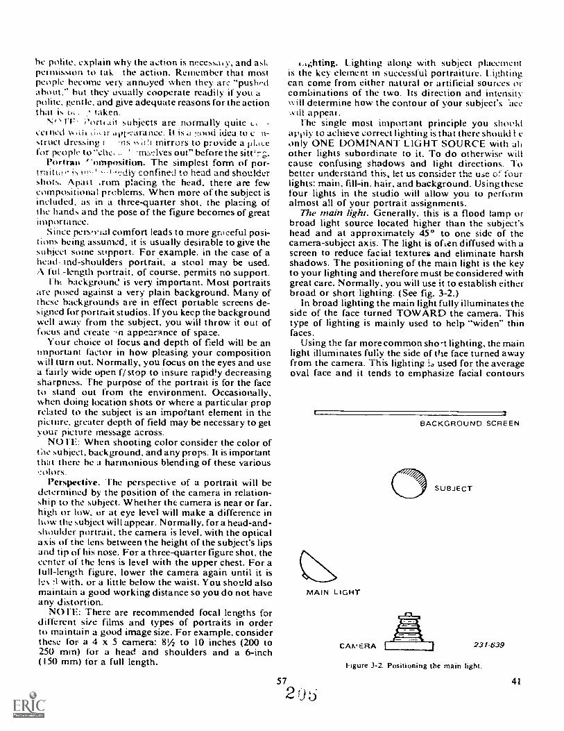
be polite. explain why the action is necessa y, and askpermission to tak the action. Remember that mostpeople become very annoyed when they are "puslwdabout," but they usually cooperate readily if you apolite, gentle, and give adequate reasons for the actionthat is taken.
N" JF 1flrI .61 subjects are normally quite 1..1cerned .tvi veara nee. It is d ,.00d idea to c flstruct dressing r ms v.;(!) mirrors to provide a pli:cefor people to -ms.Aves out" before the siWr;.
Portrait g'omposition. The simplest form of por-traitt,i.. confined to head and shouldershots. Anal t ;rorn placing the head, there are fewcompositional problems. When more of the subject isincluded, as in a three-quarter shot, the placing ofthe hands and the pose of the figure becomes of greatimportance.
Since pers,rial comfort leads to more graceful posi-tions being assumed, it is usually desirable to give thesubject some sopport. For example. in the case of ahe:RI-And-shoulders portrait, a stool may be used.A ful.-length portrait, of course, permits no support.
hackgroun t! is very important. Most portraitsare posed against a very plain background. Many ofthese backgrounds are in effect portable screens de-signed for portrait studios. If you keep the backgroundwell away from the subject, you will throw it out offocus and create n appearnce of space.
Your choice ot focus and depth of field will be aniinportant factor in how pleasing your compositionwill turn out. Normally, you focus on the eyes and usea fairly wide open f/ stop to insure rapidly decreasingsharpness. The purpose of the portrait is for the faceto stand out from the environment. Occasionally,when doing location shots or where a particular proprelated to the subject is an impottant element in thepictnre, greater depth of field may be necessary to getyour picture message across.
NO FE: When shooting color consider the color oftile subject, background, and any props. It is importantthat there be a harmonious blending of these various
Perspective. The perspective of a portrait will bedetermined by the position of the camera in relation-ship to the subject. Whether the camera is near or far.high or low, or at eye level will make a difference inhow the subject will appear. Normally, for a head-and-shoulder portrait, the camera is level, with the opticalaxis of the lens between the height of the subject's lipsand tip of his nose. For a three-quarter figure shot, thecenter of the lens is level with the upper chest. For afull-length figure, lower the camera again until it islus 1 with, or a little below the waist. You should alsomaintain a good working distance so you do not haveany distortion.
NOTE: There are recommended focal lengths fordifferent site films and types of portraits in orderto maintain a good image size. For example, considerthese for a 4 x 5 camera: 81/2 to 10 inches (200 to250 mm) for a head and shoulders and a 6-inch(150 mm) for a full length.
hting. Lighting along with subject placementis the key element in successful portraiture. Lightingcan come from either natural or artificial sources orcombinations of the two. Its direction and intensitywill determine how the contour of your subject's 'ace
appear.Ehe single most important principle you shook1
apply to achieve correct fighting is that there should I conly ONE DOMINANT LIGHT SOURCE with allother lights subordinate to it. To do otherwise willcause confusing shadows and light directions. Tobetter understand this, let us consider the use of fourlights: main, fill-in, hair, and background. Using thesefour lights in the studio will allow you to performalmost all of your portrait assignments.
The main light. Generally, this is a flood lamp orbroad light source located higher than the subject'shead and at approximately 45° to one side of thecamera-subject axis. The light is often diffused with ascreen to reduce facial textures and eliminate harshshadows. The positioning of the main light is the keyto your lighting and therefore must be considered withgreat care. Normally, you will use it to establish eitherbroad or short lighting. (See fig. 3-2.)
In broad lighting the main light fully illuminates theside of the face turned TOWARD the camera. Thistype of lighting is mainly used to help "widen" thinfaces.
Using the far more common sho7t lighting, the mainlight illuminates fully the side of the face turned awayfrom the camera. This lighting used for the averageoval face and it tends to emphasize facial contours
MAIN LIGHT
57
206
CAIVERA
BACKGROUND SCREEN
0 SUBJECT
231-639
Figure 3-2. Positioning the main light.
41
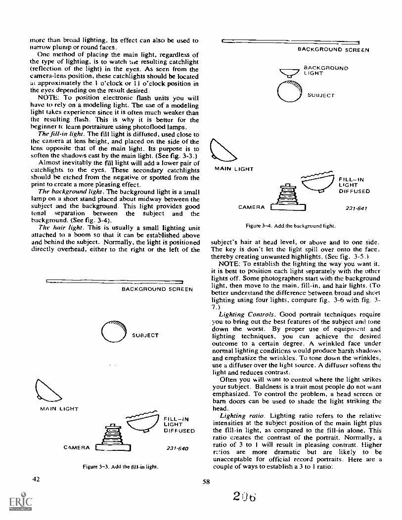
more than broad lighting. Its effect can also be used tonan-ow plump or round faces.
One method of placing the main light, regardless ofthe type of lighting, is to watch hie resulting catchlight(reflection of the light) in the eyes. As seen from thecamera-lens position, these catchlights should be locatedat approximately the 1 o'clock or I I o'clock position inthe eyes depending on the result desired-
NOTE: To position electronic flash units you willhave to rely on a modeling light. The use of a modelinglight takes experience since it is often much weaker thanthe resulting flash. This is why it is better for thebeginner tc. learn portraiture using photoflood lamps.
The fill-in light. The fill light is diffused, used close tothe camera at lens height, and placed on the side of thelens opposite that of the main light. Its purpose is tosoften the shadows cast by the main light. (See fig. 3-3.)
Almost inevitably the fill light will add a lower pair ofcatchlights to the eyes. These secondary catchlightsshould be etched from the negative or spotted from theprint to create a more pleasing effect.
The background light. The background light is a smalllamp on a short stand placed about midway between thesubject and the background. This light provides goodtonal separation between the subject and thebackground. (See fig. 3-4).
The hair light. This is usually a small lighting unitattached to a boom so that it can be established aboveand behind the subject. Normally, the light is positioneddirectly overhead, either to the right or the left of the
BACKGROUND SCREEN
SUBJECT
Figure 3-3. Add the fill-in light.
42
FILL-INLIGHTDIFFUSED
231-640
58
1
BACKGROUND SCREEN
MAIN LIGHT
BACKGROUNDLIGHT
0 SUt3JECT
FILL-INLIGHTDIF FUSED
CAMERA 231. 641
Figure 3-4. Add the background light.
subject's hair at head level, or above and to one side.The key is don't let the light spill over onto the face.thereby creating unwanted highlights. (See fig. 3-5.)
NOTE: To establish the lighting the way you want it,it is best to position each light separately with the otherlights off. Some photographers start with the backgroundlight, then move to the main, fill-in, and hair lights. (Tobetter understand the difference between broad and shortlighting using four lights, compare fig. 3-6 with fig. 3-7.)
Lighting Controls. Good portrait techniques requireyou to bring out the best features of the subject and tonedown the worst. By proper use of equiprnent andlighting techniques, you can achieve the desiredoutcome to a certain degree. A wrinkled face undernormal lighting conditicns would produce harsh shadowsand emphasize the wrinkles. To tone down the wrinkles.use a diffuser over the light source. A diffuser softens thelight and reduces contrast.
Often you will want to control where the light strikesyour subject. Baldness is a trait most people do not wantemphasized. To control the problem, a head screen orbarn doors can be used to shade the light striking thehead.
Lighting ratio. Lighting ratio refers to the relativeintensities at the subject position of the main light plusthe fill-in light, as compared to the fill-in alone. Thisratio creates the contrast of the portrait. Normally, aratio of 3 to I will result in pleasing contrast. Higherrctios are more dramatic but are likely to beunacceptable for official record portraits. Here are acouple of ways to establish a 3 to I ratio:
2 3J
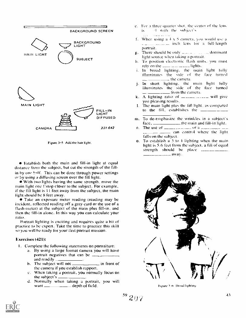
HAIR LIGHT
MAIN LIGHT
CAMERA
e. For a three-quarter shot. the center of the lensBACKGROUND SCREEN is '1 w ith the subje,-1',
BACKGROUNDLIGHT
SUBJECT
Figure 3-5. Add the hair light.
FILLINLIGHTDIF FUSED
231-642
Establish both the main and fill-in light at equaldistance from the subject, but cut the strength of the fin-in by ono !roll.. This can be done through power settingsor 'oy using a diffusing screen over the fill light.
With two lights having the same strength, move themain light one f'stop closer to the subject. For example,if the fill light is I I feet away from the subject, the mainlight should be 8 feet away.
Take an exposure meter reading (reading may beincident. reflected reading off a gray card or the use of aflash-meter) at the subject of the main plus fill-in, andthen the fill-in alone. In this way you can calculate yourratio.
Portrait lighting is exciting and requires quite a bit ofpractice to he expert. Take the time to practice this skinso you will be ready for your first portrait mission.
Exercises (421):
I . Complete the following statements on portraiture:a. By using a large format camera you will have
portrait negatives that can beand readily
h. The subject win not in front ofthe camera if you establish rapport.
c. When taking a portrait, you normally focus onthe subject's
d. Normally when taking a portrait, you willwant depth of field.
1. Wher using a 4 x 5 camera. \ ou would uso ainch lens tor a full-length
portrait.g. There should be only dominant
light source w hen taking ,1 portrait.h. To positlOn units. you musl
rdy on thei. In broad lightine,. the inain light fully
illuminate, the skit.. of the face turnedthe camera.
j. In short hghting, the main light fullyilluminates the side of the face turned
from the CaMera.k. A hghting ratio of win give
you pleasing results.I. The main light plus the fin light, as compared
to the fill, estabhshes the
rn. To de-emphasize the wrinkles in a subject'sface, the main and fill-in light.
n. The use of or acan control where the light
falls on the subject.o. To establish a 3 to I lighting when the main
light is 5.6 feet from the subject. a fill of equalstrength should be place
away.
592 0.?
g"
hgure Broad lightinp
43

3-2. Identification and Passport PhotographyNearly 'all Government agencies and military
installations use photographs on passes, identificationcards. badges. and passports; and in personnel files andrecords as one of the means of positive identification ofpersonnel. For each particular assignment, therequirements of size. pose, etc.. may differ. Therefore,before you make any exposures. consult the appropriateregulations to determine the exact requirements that thephotographs must meet.
422. Specify the requirements and some of thephotographic techniques used in identification andpassport photography.
You must never forget that the purpose of theidentification lotoglaph is just that---a photographfrom which the derson can be identified. Its purpose isnot
59 a 45
to "glamorize" the subject or make the individuallook "pretty": it is to portray any and all features, bothgood and bad, which serve to identify that particularindividual from all others.
Photography is one of the most positive and eco-nomical methods of identification. For this reasonpictures have long been used for identification pur-poses. !n recent years, there have been two noticeablet [click in identification photography: (1) the emergenceof new and varied applications and (2) a sharp increasein the use of color photos. Let us therefore take upthe requirements of passport and identification pho-tography.
Passport Photography. The Department of Stateis the authority for passports. It establishes the guide-lines for submissions of applications for passports.he portions you need to be most interested in dealwith the photos that must be included with the ap-plication.
Size. The image size of the subject's head must beno less than I inch and no larger than 13/8 inches. Thisnwasurement is made from the bottom of the chin tothe top of the head including hair. An easy way to keepthe image of the head the proper size is to mark theground glass at the proper places and then when yoi,compose. keep the image of the head between yourmarks.
Sometimes you may need to have two or morepeople in the picture. If this is the case, the imagemust be large enough so that each person can be easilyrec ognized.
When the passport picture is printed, it must be2 2 inches. Usually it is contact printed. Therefore,it is a must that the picture area on the negative be2 x 2 also. You may wish to mark the ground glass forthis measurement, too. A piece of paper or film leaderwith a 2-inch square hole in it may be used on theground glass instead of marking it with a grease pencil.
P,).ving. The subject may be shown as relaxed andl'he photo must portray a good likeness of
and satisfactorily identify the subject. The subjectshould be in imrina I street attire, without a hat. Darkglasses are not acceptable unless they are requiredI or medical reasons. Applicants who are in the activeservice of the Armed Forces and who are going abroadin the discharge of their duties may be shown in theuniform of the Armed Forces of the United States.
Ihe suhject must be shown in a clear, front, fullface view against a plain light background.
Paper. .1.wo prints of each applicant must be madeon thin, imnglossy paper. They may be color or black-a nd-white.
Identification Pictures. Identification pictures aremade for use on all types of military ID cards andclassified area badges. Identification photography isollen done by the Security Police since identificationforms are normally filled out and registered in theSecurity Police, Pass and ID section. The size of theidentification picture cannot exceed 1 x 11/4 (2.54 x3.1tf cm) inches in a vertical format. It must be a fullfront shot of the face and cannot be retouched. The46
picture will also include a title board containing in-formation set down by pertinent directives.
This type of identification photography is oftendone with a Polaroid camera designed for identifica-tion work. Such a camera permits quick results with anumber of different lighting setups. More importantly,a nonprofessional photographer can be trained tooperate it and make the necessary adjustments to ob-tain satisfactory results.
Lighting. The lighting arrangement used for anyidentification or passport-type picture must be even,weli-balanced, "flat" lighting. This type of lightingwill not hide any identifying facial marks, such asscars, moles, etc., which could be used for .efiniteidentification of the individual. To obtain flat lighting,both the main and fill light are placed at a 45 angleto the subject, giving you a I :1 lighting ratio.
60
Exercises (422):1. What is the purpose of an identification photo-
graph?
2. Which Government agency provides the guidancefor producing passport photos?
3. What is the smallest size a passport photo may he?
4. What type of lighting should you use for passportand identification photos?
5. Explain why you should not try to glamoriic pass-port and identification photos.
3-3. Special Assignment PhotographsSuppose you wanted to be an instructor at Lowry
in the Basic Still Photo Course. What would you do?You would go to your CBPO to find out how to applyfor instructor duty. Among all the other requirements.you will find that you have to send two full lengthphotos of yourself in uniform.along with your applica-tion. Since you area photographer, this is no problem.But what about all the other people on base who wouldlike to be instructors in their career fields. or thepeople who are applying for some other type of specialduty assignment? If they need a photo to send withtheir application, where do they go? Simple theycome to your lab and you will have to produce thepictures of them for their application.
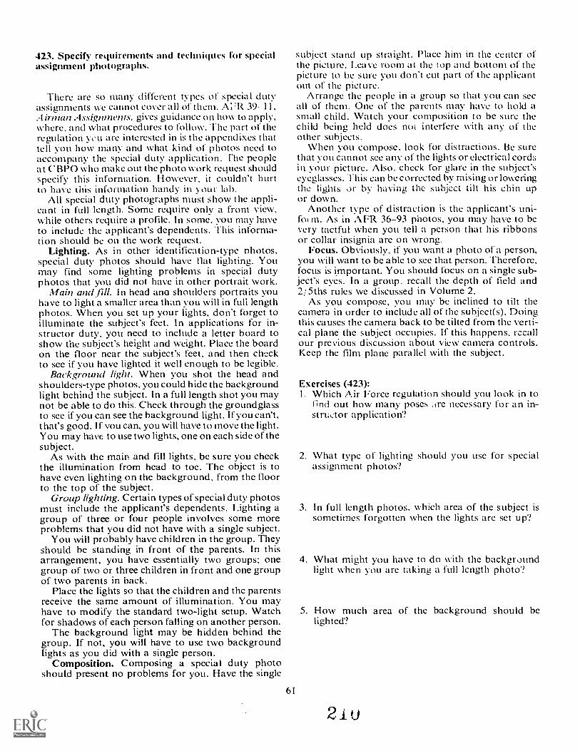
423. Specify requirements and teclmiques for specialassiginnent photographs.
There arc so many difkrent types of special dutyassignments we cannot cover all of them. A:'R 39-11,A irman Assignnwnts, gives guidance on how to apply,where, and what procedures to follow. he part of theregulation you are interested in is the appendixes thattell you how many and what kind of photos need toaccompany the special duty application. 'Fhe peopleat CBPO who make out the photo work request shouldspecify this information. However. it couldn't hurtto have this information handy in your lab.
All special duty photographs must show the appli-cant in full length. Some require only a front view,while others require a profile. In some, you may haveto include the applicant's dependents. This informa-tion should be on thc work request.
Lighting. As in othcr identification-type photos,special duty photos should have flat lighting. Youmay find some lighting problems in special dutyphotos that you did not have in othcr portrait work.
Main and fill. In head ana shoulders portraits youhave to light a smaller area than you will in full lengthphotos. When you sct up your lights, don't forget toilluminate the subject's feet. In applications for in-structor duty, you necd to include a letter board toshow the subject's height and weight. Place the boardon the floor near the subject's feet, and then checkto see if you have lighted it well enough to be legible.
Background light. When you shot the head andshoulders-type photos, you could hide the backgroundlight behind the subject. In a full length shot you maynot be able to do this. Check through the groundglassto see if you can see the background light. If you can't,t hat's good. If you can, you will have to move the light.You may have to use two lights, one on each side of thesubject.
As with the main and fill lights, be sure you checkthe illumination from head to toe. The objcct is tohave even lighting on the background, from the floorto the top of the subject.
Group lighting. Certain types of special duty photosmust include the applicant's dependents. Lighting agroup of three or four people involves some moreproblems that you did not have with a single subject.
You will probably have children in the group. Theyshould be standing in front of the parents. In thisarrangement, you have essentially two groups: onegroup of two or three children in front and one groupof two parents in back.
Place the lights so that the children and the parentsreceive the same amount of illumination. You mayhave to modify the standard two-light setup. Watchfor shadows of each person falling on another person.
The background light may be hidden behind thegroup. If not, you will have to use two backgroundlights as you did with a single person.
Composition. Composing a special duty photoshould present no problems for you. Have the single
61
subject stand up straight. Place him in thc center ofthe picture. Leave mom at the top inci botturn of thepicture to he sure you don't cut part of the applicantout of the picture.
Arrange the people in a group so that you can seeall of them. One of thc parents may have to hold asmall child. Watch your composition to be sure thechild being held does mil interfere with any of theother subjects.
When vou compose, look for distractions. 13c Surethat you cannot see any of thc lights or electrical cordsin your picture. Also, check for glare in the subject'seyeglasses. This can be corrected by raising or loweringthe lights or by having the subject tilt his chin upor down.
Another type of distraction is the applicant's uni-fol m. As in AFR 36-93 photos, you may have to bcvery tactful when you tell a person that his ribbonsor collar insignia are on wrong.
Focus. Obviously, if you want a photo of a person,you will want to be able to sce that person. Therefore,focus is kmportant. You should focus on a single sub-ject's eyes. In a group, recall thc depth of field and2/ 5ths rules we discussed in Volume 2.
As you compose, you may be inclined to tilt thecamera in order to include all of the subject(s). Doingthis causes the camera back to be tilted from the verti-cal plane thc subject occupies. If this happens, recallour previous discussion about view camera controls.Keep thc film plane parallel with the subject.
Exercises (423):I. Which Air Force regulation should you look in to
find out how many poses are necessary for an in-structor application?
2. What type of lighting should you use for specialassignment photos?
3. In full length photos, which area of the subject issometimes forgotten when the lights arc set up?
4. What might you have to do with thc backgroundlight when you are taking a full length photo?
5. How much area of thc background should belighted?
21u
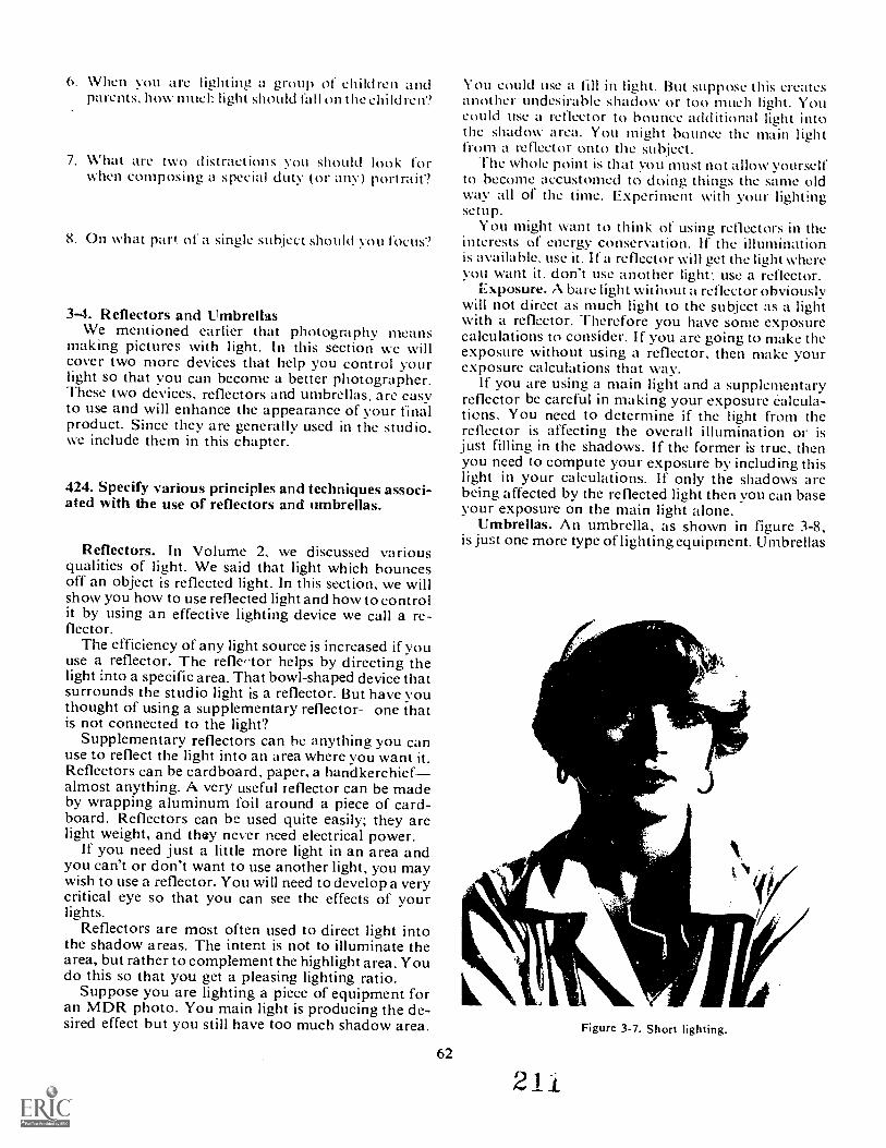
O. When you zire lighting a group of children andparents, how nmel-, light should fall on the children?
7. What ti-e two (1 istractions you should look forwhen composing a special duty (or any) portrait'?
8. On what par( of a single subject should You focus'?
3-4. Reflectors and UmbrellasWe mentioned earlier that photography means
making pictures with light. In this section wc willcover two more devices that help you control yourlight so that you can become a better photographer.These two devices, reflectors and umbrellas, are easyto use and will enhance the appearance of your finalproduct. Since they are generally used in the studio,we include them in this chapter.
424. Specify various principles and techniques associ-ated with the use of reflectors and umbrellas.
Reflectors. In Volume 2, we discussed variousqualities of light. We said that light which bouncesoff an object is reflected light. In this section, we willshow you how to use reflected light and how to controlit by using an effective lighting device we call a re-flector.
The efficiency of any light source is increased if youuse a reflector. The refle,.tor helps by directing thelight into a specific area. That bowl-shaped device thatsurrounds the studio light is a reflector. But have youthought of using a supplementary reflector- one thatis not connected to the light?
Supplementary reflectors can he anything you canuse to reflect the light into an area where you want it.Reflectors can be cardboard, paper, a handkerchiefalmost anything. A very useful reflector can be madeby wrapping aluminum foil around a piece of card-board. Reflectors can be used quite easily; they arelight weight, and thay never need electrical power.
If you need just a little more light in an area andyou can't or don't want to use another light, you maywish to use a reflector. You will need to develop a verycritical eye so that you can see the effects of yourlights.
Reflectors are most often used to direct light intothe shadow areas. The intent is not to illuminate thearea, but rather to complement the highlight area. Youdo this so that you get a pleasing lighting ratio.
Suppose you are lighting a piece of equipment foran MDR photo. You main light is producing the de-sired effect but you still have too much shadow area.
62
ou could use a fill in light. But suppose this createsanother undesirable shadow or too much light. Youcould use a reflector to bounce additional light intothe shadow area. You might bounce the main lightfrom a reflector onto the subject.
The whole point is that you must not allow yourselfto become accustomed to doing things the same oldway all of the time. Experiment with your lightingsetup.
You might want to think of using reflectors in theinterests of energy conservation. If the illuminationis available, use it. If a reflector will get the light whereyou want it, don't use another light; use a reflector.
Exposure. A bare light without a reflector obviouslywill not direct as much light to the subject as a lightwith a reflector. Therefore you have sonic exposurecalculations to consider. If you are going to make theexposure without using a reflector, then make yourexposure calculations that way.
If you are using a main light and a supplementaryreflector be careful in making your exposure Calcula-tions. You need to determine if the light from thereflector is affecting the overall illumination or isjust filling in the shadows. If the former is true, thenyou need to compute your exposure by including thislight in your calculations. If only the shadows arebeing affected by the reflected light then you can baseyour exposure on the main light alone.
Umbrellas. An umbrella, as shown in figure 3-8,is just one more type of lighting equipment. Umbrellas
-
2 11
Figure 3-7. Short lighting.
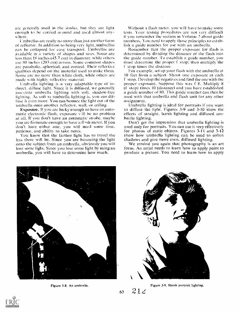
are generall used in the studio, but they arc lightenough to be carried around and used almost any-w here.
I. mbrellas are really no more than just another formof reflector. In addition to being very light, umbrellascan be collapsed for easy transport. Umbrellas areavailable in a variety of shapes and si/es. Some areless than 18 inches (45.7 cm) in diameter, while othersare 80 inches (203 cm) across. Some common shapesare parabolic, spherical, and conical. Their reflectivequalities depend on the material used to make them.Some are no more than white cloth, while others aremade w ith highly reflective material.
Umbrella lighting is a very adaptable type of in-direct, diffuse light. Since it is diffused, we generallyassociate umbrella lighting with soft, shadow-freeliehting. As soft as umbrella lighting is, you can dif-fuse it even more. You can bounce the lieht out of theumbrella onto another reflector, wall, or ceiling.
Exposure. If you are lucky enouizh to have an auto-matic electronic flash, exposure v, ill be no problemat all. It' you don't have an automatic strobe, maybeYou are fortunate enough to have a thsh meter. If youdon't have either One, you will need some time,patience, and ability to take notes.
You know that the farther light has to travel theless there will be. Since you arc bouncing the lightonto the subject from an umbrella, obviously you willlose some light. Since you lose some light by using anumbrella, you will have to dctcrminc how much.
Figure 3-8. An umbrella.
63
Without a flash meter, you will have to make sometests. Your testing procedures are not verv difficultif vou remember the section in Volume 2 about guidenumbers. You need to apply those principles to estab-lish a guide number (or use with an umbrella.
Remember that the proper exposure for flash isdetermined by dividing the distance of the flash intothe guide number. To establish a guide number, youmust deternne the proper f stop; then multiply thef stop times the distance.
For example, set up your flash with thc umbrella at10 feet from a subject. Shoot one exposure at eachf stop. Develop the negatives and find the one with theproper exposure. Suppose this was Multiply 8(I stop) times 10 (distance) and you have establisheda guide number of 80. This guide number can then beused with that umbrella and flash unit for any otherassignment.
Umbrella lighting is ideal for portraits it' you wantto diffuse the light. Figures 3-9 and 3-10 show theeffects of straight, harsh lighting and diffused um-brella lighting.
Don't get the impression that umbrella lighting isused only for portraits. You can use it very effectivelyfor photos of static objects. Figures 3-11 and 3-12show how umbrella lighting can bc used to softenshadows and give more even, diffused lighting.
We remind you again that photography is an artform. An artist needs to learn how to apply paint toproduce a picture. You need to learn how to apply
\
VIE
Figure 3-9, Harsh portrait lighting.
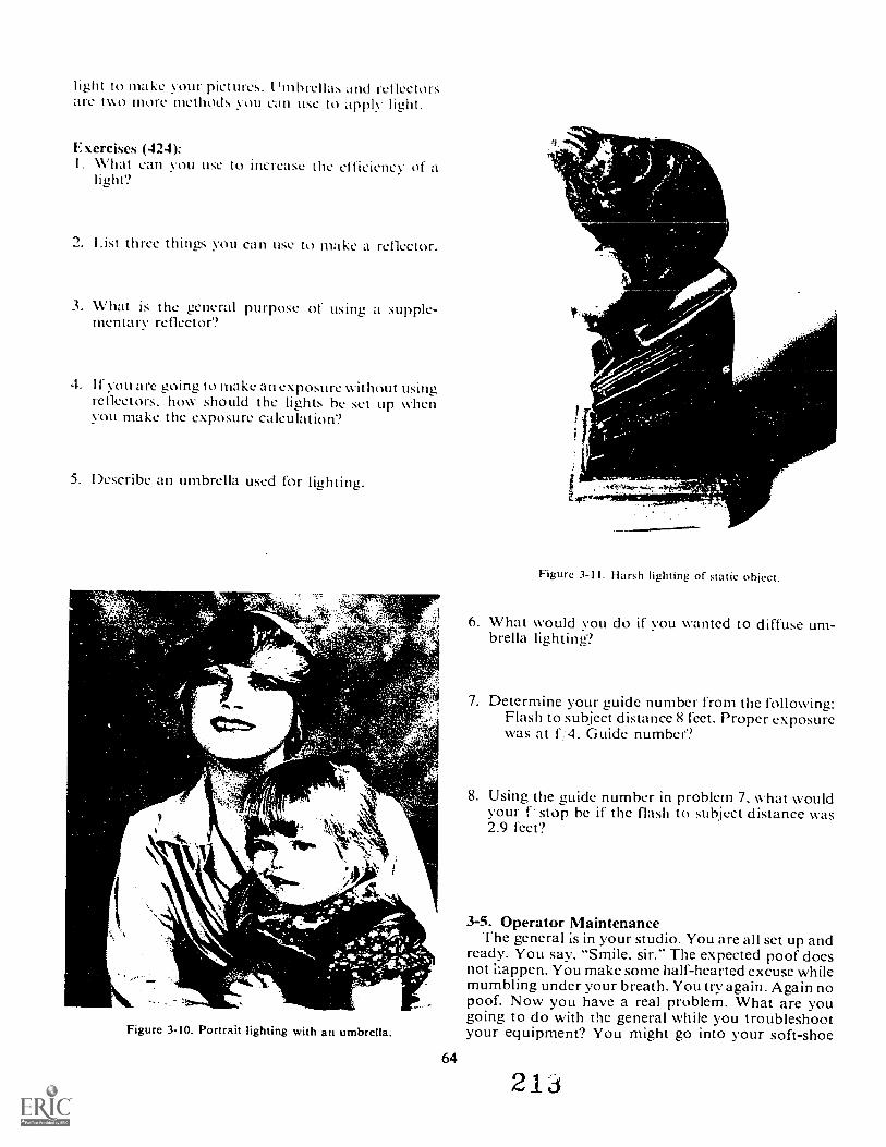
light to make your pictures. I. 'mhrellas and reflectorsare two more methods you can use to imply light.
Exercises (424):I. what to increase the efficiency oflight?
2. List three things you can use to make a reflector.
3. What is the general purpose of using a supple-mentary reflector?
4. I f you are goina to make an exposure without usingreflectors, how should the liOts be set up \Oenyou make the exposure caleukition?
5. Describe an umbrella used for lighting.
Ae,
ttPt.
Figure 3-11. Harsh lighting of static object.
6. What would vou do if you wanted to diffuse um-brella liahting?
7. Determine your auide number from the following:Flash to subject distance 8 feet. Proper exposurewas at f."4. Guide number?
8. Using the guide number in problem 7. what wouldyour 1:stop be if the flash to subject distance was2.9 feet?
Figure 3-10. Portrait lighting with an umbrella.
64
3-5. Operator MaintenanceThe general is in your studio. You are all set up and
ready. You say, "Smile. sir." The expected poof doesnot ilappen. You make some half-hearted excuse whilemumbling under your breath. You try again. Again nopoof. Now you have a real problem. What are yougoing to do with the general while you troubleshootyour equipment? You might go into your soft-shoe
2 1
routine. tell some jokes, or talk about the Air Forcebeing a great wav of life. All of this will be rather dif-ficult because vou usually become quite nervous intimes of stress. Blowing an assignment in the presenceof a general is positively a time of stress.
I-low do you prevent these equipment malfunctions?One of the best, simplest, and sure fire ways is topractice operator maintenance.
425. Specify checks to be made on cameras and light-ing equipment for proper operator maintenance.
Cameras. You can't produce a picture if yourcamera doesn't work. So. you need to check to seewhether it will work belbre you need it. Some of theareas you need to check are:
Adjustments. Be sure the front and back adju-t-ments move freely. The tilts, swings, and focustracks must not catch or stick.l_ens. Clean the lens with a earners-hair brush andlens tissue. Fold the tissue over to double thick-ness: then use a circular motion to wipe the lens.If you use lens cleaning fluid, place a drop or twoon the tissue: NOT on the lens.Shutter. Make sure the shutter opens and closeswhen you depress the cable release.Miscellaneous. Look for loose nuts, bolts. andscrews: tighten them if necessary. Check forbroken parts and light leaks: replace or fix asrequired.
Lighting Equipment. Since you need light to make aphotographic exposure you need to check them out,too. The areas of concern are:
Electrical cords. Make sure there are no barewires. Check the plugs that go into the wall recep-tacle and into the flash units for loose prongsor wires.Incandescent. Turn on the photofloods to see ifthey work. If they don't, check the connectionsand make sure the bulbs are in tightly.Electronic flash. Check all connections. Fire thelights to see if they will work. Connect the flashunits to the camera and make sure they workwhen you trip the shutter. Be sure each bulb isseated properly.Reflectors. Check to be sure each reflector isattached properly to its lamp or separate stand,Miscellaneous. Check for loose nuts, screws, andbolts and tighten them as necessary.
4111111'
Figure 3-12. Umbrella lighting of static object.
Exercises (425):Be sure that the front and back movements of thestudio camera move
2. When cleaning a lens, fold the lens tissue tothickness.
3. Check electrical cords for wires.4. If the photofloods do not come on, vou should
check the and make sure theare in
5. The electronic flash units shouldwhen you the shutter.
6. With a camera or lightine, equipment you need tocheck and tighten looseand
65 2
CHAPTER 4
Reproduction Photography
THE TERM "COPYING," as used in photography,means the photographic reproduction of anotherphotograph, drawing, map, chart, or similar flat-planeobject. Reproductions of this type have a number ofuses. Consider several examples. If a negative is lost orunavailable, a duplicate may be made by copying aprint made from the original negative. Valuable docu-ments, if used constantly, soon become worn andillegible; however, by making reproductions throughthe process of copying, you can preserve the original.On some occasions, it mal be desirable to reproducethe subject at a different scale or size; this change, too,can be effected by copying. Again, in some instances,a great quantity of prints from a single negative issometimes requested with a deadline for delivery. Insuch cases, duplicate negatives may be made andgiven to as many printing teams as necessary in orderto complete the work in the stipulated time. On otheroccasions, copying may be used to improve a photo-graphic print. For instance, stains and blemishesclearly detract from the quality of the print. lf, how-ever, such a stain or blemish is transparent or trans-lucent, it may be toned down by using a filter that isdeeper than the color of the stain.
Every picture which you see in a newspaper, book,or magazine has been copied at least once. Banksmake photographic records of checks received. Entirelibraries are copied on film that occupies a tiny frac-tion of the space required for the books. Copying isthus of great importance. To be successful, suchcopying requires careful work. The problem of copy-ing is complicated by the great variation in thenature of the originals to be reproduced and by thevarying conditions under which the work is to be done.
In this chapter we will discuss copying reflectivesubjects, making scale change provisions, duplicatingtranbparent material, and using specialized copyprocedures.
4-1. Copying Reflective SubjectsSubjects to be copied are broadly categorized in
two ways: reflective or transparent. Reflective sub-jects, like photographs, paintings, schematics, andmaps, are very common copy subjects. Reflectivesubjects are so identified because they are copied byreflected light rather than light passing through the
66
subject as is the case with transparencies (e.g.. slidecopying). Proper copying of reflective subjects (ortransparencies) is only achieved by proper lighting,camera operation, filter selection, exposure, and ap-propriate film/developer combinations. We have dis-cussed camera operation and filters, and we willreview particular copy exposure problems in the sec-tion on scale changes, so now let us take up the othertopics as they relate to copy work.
426. Cite techniques used for the correct lighting ofreflective copy subjects.
Copy Lighting. You can use practically any type oflighting source when making copies; included areordinary tungsten lamps, photoflood lamps, flash,fluorescent tubes, daylight, quartz iodine, and mercuryvapor systems. Regardless of the type of lights used,the basic requirement for copy lighting is even il-lumination. Uneven lighting will result in negativeswith uneven density, and the production of uniformprints that match a good original print will be impos-sible. An easy check for evenness of illumination is toplace the end of a ruler or similar opaque objectagainst the center of the subject at a slight angle. (Becareful that you do not get your body in the path of theillumination.) Balancing the shadows on each side ofthe ruler enables you to control the evenness of theintensity. Move either light, as necessary, to equalizethe lighting.
Subject material. An important consideration inlight-positioning is the subject material. For smooth,glossy surfaces, the lights will provide the best il-lumination with the least amount of reflection whenplaced at an angle of approximately 45° to the sub-ject. The lights should be moved more nearly parallelfor rough surfaced material. An angle of 75° willminimize texture detail and help assure higher qualityreproduction. (See fig. 4-1).
Reflection control. Two conditions generally causereflections in copy work. is reflection of the lightsource; the other is r ,2ctions over the entire surfaceof the copy subject
Reflections of the light source are caused by lightreflections from the camera stand, lensboard, or any
210
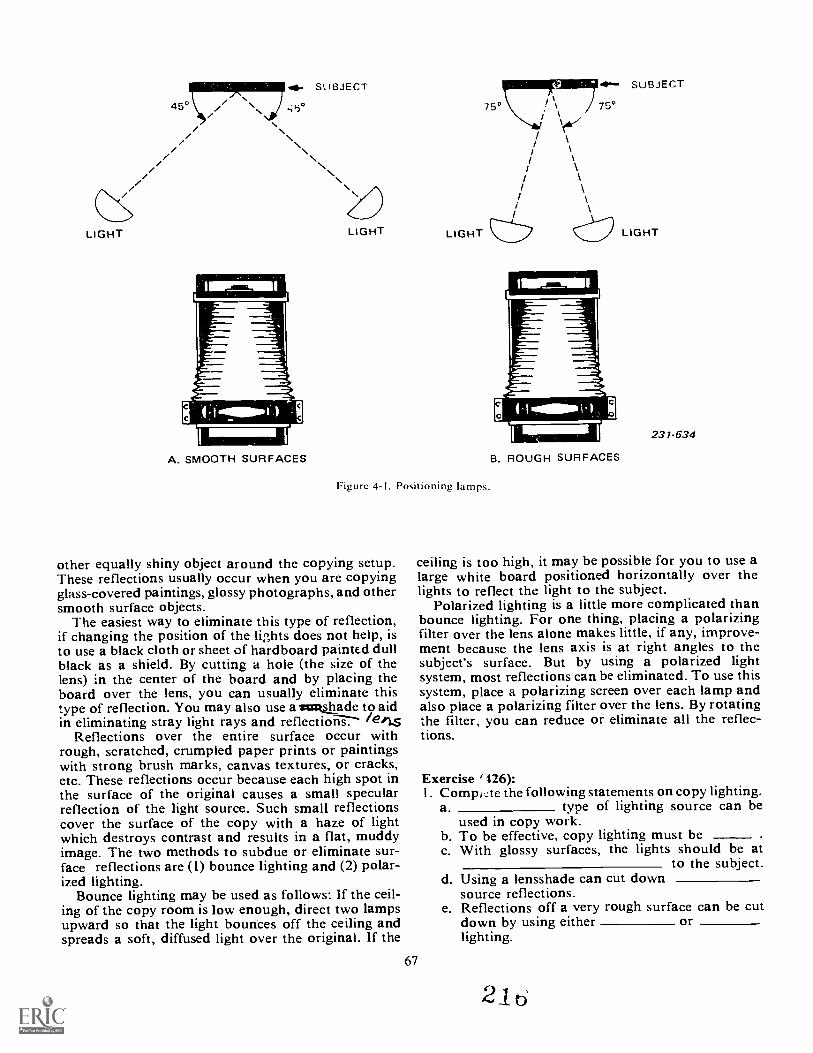
45° . \ 45017111717SUBJECT
LIGHT LIGHT
A. SMOOTH SURFACES
SUBJECT
750
I \
LIGHT
Figure 4-1. Positioning lamps.
other equally shiny object around the copying setup.These reflections usually occur when you are copyingglass-covered paintings, glossy photographs, and othersmooth surface objects.
The easiest way to eliminate this type of reflection,if changing the position of the lights does not help, isto use a black cloth or sheet of hardboard painted dullblack as a shield. By cutting a hole (the size of thelens) in the center of the board and by placing theboard over the lens, you can usually eliminate thistype of reflection. You may also use a waskshade to aidin eliminating stray light rays and ref1ecti6iig7s /ens
Reflections over the entire surface occur withrough, scratched, crumpled paper prints or paintingswith strong brush marks, canvas textures, or cracks,etc. These reflections occur because each high spot inthe surface of the original causes a small specularreflection of the light source. Such small reflectionscover the surface of the copy with a haze of lightwhich destroys contrast and results in a flat, muddyimage. The two methods to subdue or eliminate sur-face reflections are (1) bounce lighting and (2) polar-ized lighting.
Bounce lighting may be used as follows: If the ceil-ing of the copy room is low enough, direct two lampsupward so that the light bounces off the ceiling andspreads a soft, diffused light over the original. If the
67
cp
B. ROUGH SURFACES
LIGHT
231-634
ceiling is too high, it may be possible for you to use alarge white board positioned horizontally over thelights to reflect the light to the subject.
Polarized lighting is a little more complicated thanbounce lighting. For one thing, placing a polarizingfilter over the lens alone makes little, if any, improve-ment because the lens axis is at right angles to thesubject's surface. But by using a polarized lightsystem, most reflections can be eliminated. To use thissystem, place a polarizing screen over each lamp andalso place a polarizing filter over the lens. By rotatingthe filter, you can reduce or eliminate all the reflec-tions.
Exercise ' 426):I. CompLte the following statements on copy lighting.
a type of lighting source can beused in copy work.
b. To be effective, copy lighting must bec. With glossy surfaces, the lights should be at
to the subject.d. Using a lensshade can cut down
source reflections.e. Reflections off a very rough surface can be cut
down by using either orlighting.
21
427. Identify characteristics, problems, and techniquesassociated with the copying of different types ofreflective subjects.
Reflective Copy Subjects. Let us discuss specificproblems of copying different types of reflectivesubjects.
Black-arul-white line drawings. There are a numberof documents and originals that fan into this category.For example. you may be required to copy suchthings as maps that are printed in black-and-white,schematic drawings, pages of typed material, recallrosters, and organizational charts.
Generally speaking, a line original has but twotonesblack (or a dark shade of gray) and white (or avery light shade of gray). As far as contrast is con-cerned, these two tones should be separated as muchas possible. The net result is a high-contrast negative;and when combined with printing on a high-contrastpaper. the high contrast of the original is maintained.Remember, under these high-contrast conditions,film latitude is very short and the exposure is critical.Consequently, if you miss the exposure, you are takinga chance of filling in or obliterating fine lines. Toavoid this, you should allow ample exposure but notoverexposure of the film.
If the black-and-white material is printed on justone side, it may be backed with vte paper to in-crease the contrast. This ;s especially true if theoriginal had been printcd on rather thin paper, inwhich case the dark color of the easel may 3hine.
Joke*/ through. If the material being copied has been printedon both sides, such as you might find if you werecopying a page from a magazine, the ink from thereverse side may possibly show through. Should youencounter such a situation, it would be wise to backthe original being copied with black paper in order toavoid recording the material on the reverse side.
Colored line originals. In general, the technique ofcopying colored line originals onto black-and-whitefilm is essentially the same technique as that used forcopying black-and-white material. Among the coloredline subjects which you may be required to copy aremaps that have been printed in several colors in orderto define different terrain features; drawings thathave been printed in colored ink, with the color identi-fying various mechanical features; and blueprints.The usual problem is to obtain the greatest contrastbetween the line and the background materials.Typically, it is best to use panchromatic film for thistype of copying, since filters are most frequently usedto obtain the high degree of contrast that is necessary.For example, when copying a blueprint maximumcontrast can be obtained by using a red filter whichwill cause the blue background of the diagram to ap-pear clear on the negative.
68
Black-and-white continuous tone originals. Themost common black-and-white, continuous tone orig-inal that you will be required to copy will undoubtedlybe a photographic print. A good copy negative madefrom such a print should closely resemble the originalnegative. It should have the same gradation in tonesas the original. .Accurate rendition of this type oforiginal requires the use of a film with a mediumcontrast, as well as the correct exposure and develop-ment. Obviously, if you underexpose a negative in acamera, you lose shadow detail. The same is true incopying. By the same reasoning, overexposure ineither situation causes a blocking of highlight detail.
Very often you ilay bc required to copy old photo-graphs that are wrinkled or creased. These wrinkles orcreases generally cause reflections. The print may beflattened out by pressing the print under a piece ofheavy glass. You will then have to use the appropriatelighting to reduce reflections off the glass surface.
Ordinarily, if the print is badly soiled, it should becleaned before copying. If., however, it is a valuableprint, you should obtain the best possible copy repro-duction before attempting any cleaning. Of course, ifdamage to the old original is considerable. you obtainthe best possible copy; then retcuch the resulting printand recopy it.
Stained prints can be copied on panchromaticfilm. When you do this, use a filter as close as possibleto the color of the stain. In fact, for best results, thecolor of the filter you use should be somewhat deeperthan the color of the stain. For example, if a print has ayellow stain, it should be copied on panchromatic filmin conjunction with a deep yellow filter.
In contrast with stained prints, copying faded printsis different. For one thing, if the image has turned yel-low with age, you must restore its original brilliance.Consequently, you should use a filter which is op-posite in color to the faded image. For example, if theimage has turned yellowish-brown, you can copy theprint on panchromatic film with a blue filter. In such aLase, you may find that rather than using panchro-matic film, it is simpler to use blue-sensitive filmwithout a filter.
Color cominuous tone. Various types of color con-tinuous tone originals may be successfully copiedonto black and white. Examples of these include wateror oil color paintings, color photographic prints, ormagazine illustrations. Typically, you would use pan-chromatic film of moderate contrast. Filtration may benecessary if you need to achieve contrastier tonalseparations.
A soiled color print iisay be very difficult to cleanbecause of the nature of the dyes that make up theimage. You may find that the best way is to copy thesoiled print and then retouch the print made from thecopy negative. The retouched print then can he copied.
Stained color prints can be copied through the ap-propriate filter. The filter should be darker than thestain color. One problem is that the filter will affectthe other colors of the print.
21 ''
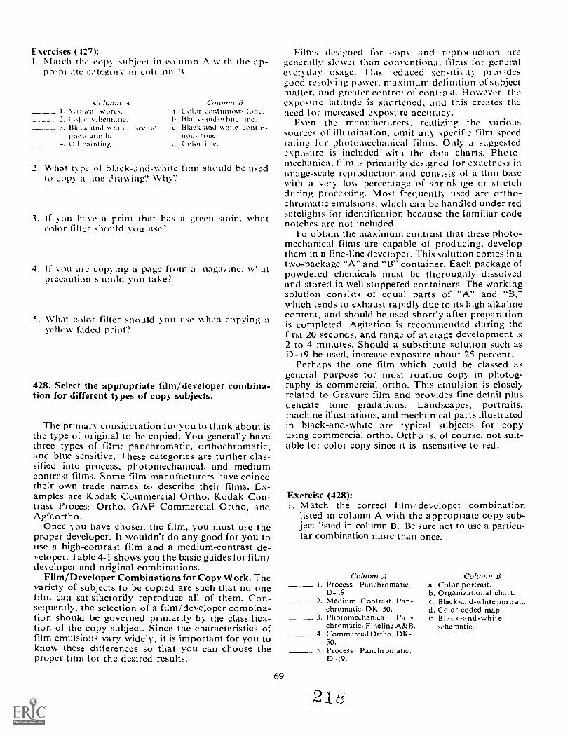
Exercises (427):Match the cop subject in colunm A with the ap-propriate category M column B.
column Column BI. VI scores, t. Co lot continuous tone.
schematic. h. Rlack-and-hite hne.hite scenic c. Black-and-Mnte contin-
photograph. non. tone.4. Oil painting. d. Coloi
2. What type of black-and-white film should be usedto copy a line i ra wing? Why?
3. If you have a print that has a green stain, whatcolor filter should yoLl use
4. If you are copying a page from a magazine, w' atprecaution should you take?
5. What color filter should you use whcri copying ayellow faded print?
428. Select the appropriate film/developer combina-tion for different types of copy subjects.
The primary consideration for you to think about isthe type of original to be copied. You generally havethree types of film: panchromatic, orthochromatic,and blue sensitive. These categories are further clas-sified into process, photomechanical, and mediumcontrast films. Some film manufacturers have coinedtheir own trade names to describe their films. Ex-amples are Kodak Cotnmercial Ortho, Kodak Con-trast Process Ortho, GAF Commercial Ortho, andAgfaortho.
Once you have chosen the film, you must use theproper developer. It wouldn't do any good for you touse a high-contrast film and a medium-contrast de-veloper. Table 4-I shows you the basic guides for film/developer and original combinations.
Film/Developer Combinations for Copy Work. Thevariety of subjects to be copied are such that no onefilm can satisfactorily reproduce all of them. Con-sequently, the selection of a film/developer combina-tion should be governed primarily by the classifica-tion of the copy subject. Since the characteristics offilm emulsions vary widely, it is important for you toknow these differences so that you can choose theproper film for the desired results.
Films designed for copy and reproduction aregenerally slower than conventional films for generaleveryday usage. This reduced sensitivity providesgood resolving power, maximum definition of subjectmatter, and greater control of contrast. H owever, theexposure latitude is shortened, and this creates theneed for increased exposure accuracy.
Even the manufacturers, realizing the varioussources of illumination, omit any specific film speedrating Mr photomechanical films. Only a suggestedexposure is included with the data charts. Photo-mechanical film iF primarily designed for exactness inimage-scale reproductior. and consists of a thin basewith a very low percentage of shrinkage or stretchduring processing. Most frequently used are ortho-chromatic emulsions, which can be handled under redsafelights for identification because the familiar codenotches are not included.
To obtain the maximum contrast that these photo-mechanical films are capable of producing, developthem in a fine-line developer. This solution comes in atwo-package "A" and "B" container. Each package ofpowdered chemicals must be thoroughly dissolvedand stored in well-stoppered containers. The workingsolution consists of equal parts of "A" and "B,"which tends to exhaust rapidly due to its high alkalinecontent, and should be used shortly after preparationis completed. Agitation is recommended during thefirst 20 seconds, and range of average development is2 to 4 minutes. Should a substitute solution such asD-19 be used, increase exposure about 25 percent.
Perhaps the one film which could be classed asgeneral purpose for most routine copy in photog-raphy is commercial ortho. This emulsion is closelyrelated to Gravure film and provides fine detail plusdelicate tone gradations. Landscapes, portraits,machine illustrations, and mechanical parts illustratedin black-and-whae are typical subjects for copyusing commercial ortho. Ortho is, of course, not suit-able for color copy since it is insensitive to red.
69
Exercise (428):1. Match the correct film/developer combination
listed in column A with the appropriate copy sub-ject listed in column B. Be sure not to use a particu-lar combination more than once.
Colwnn AProcess PanchromaticD-I9.
_ 2 Medium Contrast Pan-chromatic, DK-50.
1 Photomechanical Pan-chrommic Fineline A&B.
4 Commercial Ortho, DK50.
5 Process Panchromatic,D-19.
2 1 8
Column Ba. Color portrait.b. Organizational chart.c. Black-and-white portrait.d. Color-coded map.e. Black-and-white
schematic.
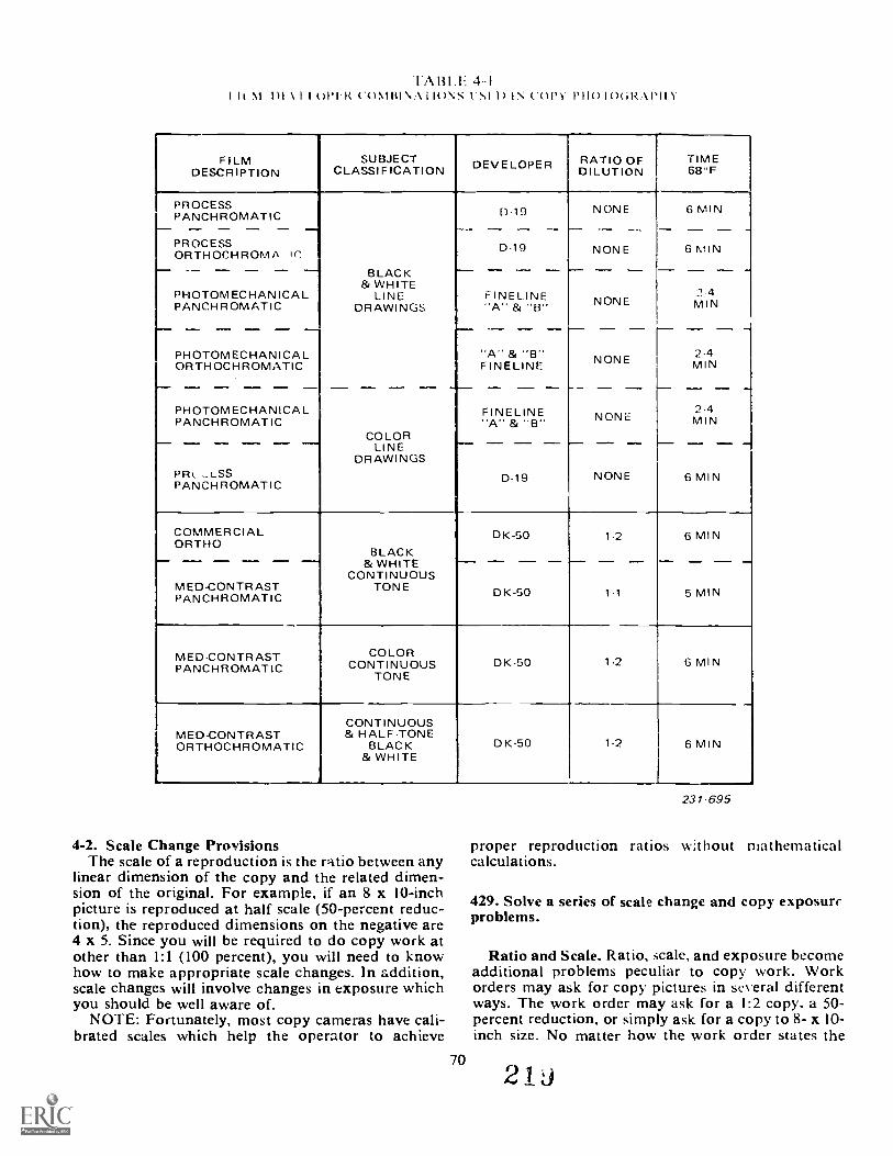
.1A1111 =. 4-1h m rh.\ I opI.R (-wow il)Ns I.N1.I) IN coN- IOGRIIII).
FILMDESCRIPTION
SUBJECTCLASSIFICATION DEVELOPER RATIO OF
DILUTIONTIME68"F
PROCESSPANCHROMATIC
,---
PROCESSORTHOCHROMA 'C,
PHOTOMECHANICALPANCHROMATIC
13:-.1-0TOMEC7IA:ICA -L-ORTHOCHROMATIC
PHOTOMECHANICALPANCHROMATIC
PIRt_ ..LSSPANCHROMATIC
BLACK& WHITE
LINEDRAWINGS
D-19
D.19
FINELINE
FINELINE
NONE
--NONE
----
NONE
NONE
.--
NONE
,-- ----
NONE
6 MIN-
6 MIN
2 -4MIN
2-4
-,
MIN
--. -.
2-4MIN
6 MIN
COLORLINE
DRAWINGS
FINELINE
D-19
COMMERCIALORTHO
MED-CONTRASTPANCHROMATIC
BLACK& WHITE
CONTINUOUSTONE
DK-50
DK-50
1-2
1-1
6 MIN
5 MIN
MED-CONTRASTPANCHROMATIC
COLORCONTINUOUS
TONEDK-50 1-2 6 MIN
MED-CONTRASTORTHOCHROMATIC
CONTINUOUS& HALF-TONE
BLACK& WHITE
DK-50 1-2 6 MIN
4-2. Scale Change ProvisionsThe scale of a reproduction is the ratio between any
linear dimension of the copy and the related dimen-sion of the original. For example, if an 8 x 10-inchpicture is reproduced at half scale (50-percent reduc-tion), the reproduced dimensions on the negative are4 x 5. Since you will be required to do copy work atother than 1:1 (100 percent), you will need to knowhow to make appropriate scale changes. In addition,scale changes will involve changes in exposure whichyou should be well aware of.
NOTE: Fortunately, most copy cameras have cali-brated scales which help the operator to achieve
231 695
proper reproduction ratios without mathematicalcalculations.
429. Solve a series of scale change and copy exposureproblems.
Ratio and Scale. Ratio, scale, and exposure becomeadditional problems peculiar to copy work. Workorders may ask for copy pictures in several differentways. The work order may ask for a 1:2 copy, a 50-percent reduction, or simply ask for a copy to 8- x 10-inch size. No matter how the work order states the
70
21
requirement, you will have to do some calculation- todetermine how much bellows extension and how muchexposure compensation you need.
Mathematics calculations for bellows extension andsubject distance. To get the difference sizes of the copywork, you need to extend or shorten the bellows andincrease or decrease the distance from the lens to thesubject. Two formulas to determine these distances are:
Bellows extension = FL x (scale + I)Subject distance =-- BE scale
Where FL = focal length, scale is the ratio, and BE =bellows extension.
Suppose you need to make a 50-percent reductionwhile using a 6-inch lens. Substitute your known factorsinto the formulas:
Bellows extension = 6 x (.5 + 1)Bellows extension = 6 x 1.5Bellows extension = 9 inches
Subject distance = 9 ÷ .5Subject distance = 18 inches
You have now determined that to make a copy at 50percent the original size you need to have 9 inchesbetween the lens and the film plane and 18 inches betweenthe lens and the subject.
We include these formulas to show you the relationshipbetween the bellows extension and the subject distance.Actually you need only to remember the bellowsextension calculations.
When you get a request to make a reduction, thesimplest way to get the proper subject distance is tomeasure the subject and its image on the ground glass. Forexample, suppose you need to make a 50-percentreduction. Measure a straight line on the original. Thenwith the proper bellows extension, move the copy boardor camera until the measured line on the original isone-half as long on the ground glass.
Another method is to place a ruler on the copy board. Ifthe original is tc be reproduced at 25 percent, adjust theimage on the ground glass until one inch on the ruler is1/4 inch on the ground glass.
Bellows extension factor. As you lengthen the bellows,the light must travel further to get to the film plane. Whenthis happens,you need to increase the exposure tocompensate for this light loss. We have one more formulato use to determine how much exposure compensation isnecessary for any given bellows extension. The formulais:
Bellows extension2
Focal length'bellows extension factor
To make a copy at the same size as the original or 1: I ,you need to extend the bellows to two focal lengths. Theincreased bellows extension causes a loss of light at thefilm plane and must be accounted for. Wc call thiscompensation the bellows extension factor. To figure out
71
how much compensation you need, measure the bellowsextension and square the factor, then square the notinalfocal length and divide that into the square of the bellowsextension. The result of that will be your bellowsextension factor.
The formula looks less confusing:
Bellows extension2
Focal length2= bellows extension factor
Solve a problem when the bellows extension is 8 inchesand the focal length is 4 inches. Go through the formula,putting in the known factors.
Bellows extension2(82)
Focal length2(42)
64 = 416
= bellows extension factor
What would be the bellows extension and bellowsextension factor needed to copy an original using a 4-inchlens when the original is to be reduced in size by 25%?Since reduction is 25%, scale is 75% (of the original).Using the formula for bellows extension we find:
BE = 4 x (.75 == I)BE = 4 x 1.75BE= 7 inches
Now that we know what bellows extension is needed,we can find the bellows extension factor (BEF), by doingthe following:
BEF = BE2
FL2
49BEF =
16
BEF = 3
We have now determined that we must increase theoriginally computed exposure by three times. Tti.exposure factor is used the same way a filter factor isused, as discussed in Volume 2. For example, if theoriginal exposure was f/8 at 4 seconds, you simplymultiply the expsoure time by the bellows extensionfactor. 4 x 3 = 12 seconds.
Now that we have gone through the hard part ofexposure compensation, we will show you the easy way.A hand-held light meter can be used effectively todetermine exposure compensation for close-upphotography. Either an incident or a reflected light metercan be used for this purpose. However, an incidentreading is best when photograr hing small objects. To usethis exposure determining method, you must know thefocal length inches of the lens you are using. Let's
47
suppose that you are using a 100-mm lens. Convert 100mm to inches by multiplying by 0.04-100 x 0.04 = 4inches. First take your light meter reading. As anexample, if your meter reading is 1/60 second at f/11,your next step is to consider the f/stop dial on your lightmeter as if it were calibrated in inches, example: 4/4 (4inches), f/5.6 (5.6 inches), etc. Rotate the f/stop dial onthe light meter so that f/4 (4 inches) lines up with 1/60second.
Now measure your lens-to-film plane distance. If thedistance is 8 inches, read the new exposure time oppositef/8 (8 inches). In this instance the new exposure timewould be 1/15 second at f/11, which would be twoadditional f/stops from the light meter reading.
Exercises (429):
I. Why do you need to increase the exposure when youlengthen the bellows?
2. Determine the bellows extension and the newexposure if: focal length is 6 inches, reduction is 50percent, and original exposure was f/8 at 1/2 second.
3. Suppose you are using a 12-inch lens, making a25-percent reduction. Calculate the bellowsextension, the bellows extension factor, and your newshutter speed if original exposure was f/ 11 at 1/2second.
4. If a measured line on the original was 4 inches, howlong should it be on the ground glass if you weremaking a 1:1 reproduction?
4-3. Processing Copy FilmAll the exposure compensation formulas in the world
will not help you get the product finished unless youprocess the film. You cannot process the film until youhave learned the proper processing procedures. We havementioned film processing in previous sections but havenot covered it too explicitly. In this section we will getmore involved with processing.
430. Specify procedures for processing copy film.
Developer6. There are so many different types ofdevelopers that we could not possibly include them all in
this section. When you need to select a particulardeveloper, you need to know its basic characteristics andpurpose. When you need this information, you shouldread the Photo Lab IndeA, published by Morgan andMorgan or the Photographic Lab Handbook, publishedby Amphoto.
The object in copy work is to get as good a reproductionas possible. So, if you know you are using a fine-grain,high-contrast film, you should use a compatibledeveloper. Kodak DI 9 or GAF 72 are two suchdevelopers. That is, they :Are both fine-grain,high-contrast developers.
Processing. Processing copy film is not much differentfrom processing any other type of film. You will beprocessing a very few sheets of film at one time, so it willprobably be easier. And since copy film is generally veryslow, you can process it under safelight conditions. Thisis called processing by inspection.
To process by inspection you must first know whatcolor(s) of light the film is sensitive to. If the film issensitive only to blue, you could use a red, green, oryellow safelight filter. The data sheet that is packed withthe film usually tells you what safelight filter you can use,how strong the light can be, how long you may have it on,and how far away the light must be from the film.
After you have made the exposure and installed theproper safelight filter, you should be ready to process thefilm. Generally, you process copy film by inspectionthroughout the developing step. Since processing byinspection is learned by experience, it is very difficult toteach it in a CDC. We have included some of the majorthings to look for as follows:
Highlights. The darkest part of the negative should beallowed to develop to the darkest density possible.Shadows. Process the film until the lightest parts ofthe image just begin to pick up density.Lines. You must watch the density build up aroundthe lines. The lines must remain clear. Stopdevelopment before the lines pick up density.
48 72
Positive Materials. Occasionally you will have tomake positive reproductions. Such things as vu-graphs,charts, and large transparencies will be requested fromyour lab. These are used for training and briefings. If youget such a request, you will need to know how to producethem. The easiest method is to use positive film.
Positive film is very slow and can be handled undersafelight conditions. It can be used as copy film exposedin the copy camera, or it can be exposed using a projectionor contact printer. It generally has a short exposurelatitude and fine grain.
You must read the data sheet to see how to expose andprocess these positive materials. Some are automatic andcan be developed in ordinary black-and-white developers.Others are called reversal films and must be developed inreversal solutions.
22i
The reversal films produce a positive image by wayof reversal processing. When the film is exposed, allof the silver is not used to record the camera image.This first exposure is processed in normal developers.The remaining silver is then exposed, developed,bleached, and fixed. The result is a positive image.
Exercise (430):1. Indicate which of the following statements are true:
a. There are only a very few developers tochoose from when processing copy film.
b. Generally, copy film can be handled undersafelights.
c. You can find safelight recommendations inthe film data sheet.
d. The lines of a copy negative must remain clear.e. Positive film is a fast, coarse-grain film.f. Reversal film must be developed twice.
4-4. Finishing Copy FilmAfter you have exposed, processed, and dried your
copy film, you must complete an operation calledfinishing. Finishing is the art of putting the finaltouches on your product. As a 3-level photographer,your finishing work will be limited to the area we callopaquing.
431. Specify procedures and techniques related tospotting and opaquing copy film.
As you recall from Volume 2, an opaque mediumdoes not transmit any light. When you produce a copyof a line drawing, you want the lines to stand out andthe background to be white in the final print. In otherwords, you want the background to be opaque.
Some of the things that keep the background frombeing opaque ate dust, lint, hair, and scratches. V. henyou print the negative, these light areas allow lightto pass through to the print. This results in dark spotson the print which are unaccepta e. The eliminationof these small spots on the negative is called spotting.
Spotting. Equipment used for spotting includesmapping pen, red dye, brush, and opaque. The penand dye are especially satisfactory for spotting thesmall areas, and the brush can be used with either thedye or the opaque for the larger at eas. The use of thebrush and the opaque is not very satisfactory for thesmall areas. Because of the flexibility of the brush,you may easily opaque too large an area. Opaque driesrapidly on the tip of a finely pointed brushoftenbefore the brush can make contact with the negative.
Place the negative on the retouching easel, printer,or plotting table with the emulsion side of the nega-tive toward the glass. Dip the mapping pen in the dye.Using good magnification, lightly touch the spot onthe back side of the negative. With care, you can
confine the dye to the spot without spreading over thesurrounding area. Use extreme care in keeping thepoint clean if fine work is to he done quickly. Youwill notice that the penpoint has a tendency to pickup small pieces of gelatin from the negative.
Because pinholes are actually small holes in theemulsion, they cannt be spotted on the emulsion sideof the negative. The capillary action draws the dyeto the sides of the hole, and the pinhole remains un-covered. At best, a pinhole is very difficult to correcton a negative; sometimes it can be successfully doneon the back of the negative with dye.
Opaquing. An example of opaquing is the elirnina-tion of an objectionable background. Covering the un-desirable portion with a light-resistant dye or opaquecompound eliminates it from the print. When such aprocedure is used, the blocked portion of the printappears white.
Begin by placing the negative on a well-illuminatedsurface, such a ; a printer, retouching easel, or plottingtable. The negative may be blocked on either side orboth sides if necessary. It is best, however, to blockon the base side of the negative. This avoids possiblescratching of the emulsion.
Saturate a cotton swab to about half its length withIA red dye. Follow the outline of the image, usingshort, side-to-side strokes. Work slowly, allowingsufficient time for the gelatin to become saturatedwith the dye. Experience and practice make it com-paratively easy to follow the outline accurately. Usethe swab the same way you would use a pencil orcrayon. It may be necessary to block on both sides ofthe negative if the area to be blocked is very thin andthe image quite dense. This would be an exceptionalcase, however. Narrow areas may be filled in with amapping pen. One common practice is to outline thesubject with a mapping pen and block the remainderof the negative with a brush. Normally, we do notcompletely reverse a background from black to white.
Dye blocking does not crack or flake off the nega-tive. Errors made may be removed by lightly wipingthe area with a cotton swab and clear water. If the dyeis not completely removed with water, use a 10-percent solution of sodium sulfite. All of the dye maybe removed ;)y soaking the negative in a tray of sucha solution. With moderate agitation, the red color andthe resulting yellow stain both disappear. Wash thenegative in running water for 5 minutes and then dryit. You may then repeat the blocking process if youdesire.
Opaque may also be used for the blocking process.Although it may have a tendency to crack and flake,it does have the advantage of complete blocking witha single application. Furthermore, it may be used in arather thick consistency and as such does not tend torun as the red dye does. It is exceptionally good forfollowing along the edges of objects.
As with any new procedure, spotting and opaquingwill become easier as you practice. The key words arepatience and practice.
73
Exercises (431):I. In high-contrast line drawings, how should the
background appear in the print?
2. List three things that prevent the background frombeing opaque in the negative.
3. Define "spotting."
4. On which side of Lite negative should you applythe spotting fluid?
5. When would you block on both sides of the nega-tive?
4-5. Operator MaintenanceAs with any other photo equipment, you must keep
copy equipment operating properly. The best way tobe sure your equipment will work is to practice goodoperator maintenance.
432. Specify procedures for proper operator main-tenance on copy equipment.
Operator maintenance in the copy room is reallyno more than commonsense houskeeping. You mustkeep everything clean and in its proper place. Remem-ber to clean the room, camera, copy board glass, andwork areas.
Room. General housekeeping is the key word in thecom room. Clean the benches, floors, and shelves.This is not really operator maintenance, but it willreduce the dust that may cause defects in your finishedfilm.
74
Camera. Check to see that all of the eamerctson-trols work properly. Clean the lens with a camel's-hair brush and lens tissue. Check for light leaks in thebellows. Clean the bellows inside and out with aslightly damp cloth. Clean, oil-free compressed airmay be used to blow dust out of the bellows. A verygentle stream of air is best to avoid damage to thebellows.
Check the ground glass back for dirt and cracks.Check and clean the area where the film rests duringexposure. Some copy cameras have a vacuum backthat keeps the film in place. Check that the vacuumholes are not clogged with dirt or pieces of film.
The copy board should be cleaned. Also, clean theglass that covers the copy board. Check that thelatches are working properly.
Lights. Make sure your lights are working properly.If not, fix or replace as required. Remove the dustfrom the lights and reflectors. Check for frayedelectrical cords and replace them if necessary.
Processing Room. Clean the processing room asnecessary. Check for leaking water lines and havethem repaired. Look for unsafe electrical conditions,such as loose, frayed and improperly secured electriccords.
Make sure your safelight filters are not broken orfaded. Replace them as necessary.
You are not expected to be an expert in photoequipment repair, but you do need to know whichitems will not or cannot work. Identify the ones youcannot fix and have the repair people fix them.
Exercise (432):I. Complete the following statements by filling in the
missing terms or phrases:a. Operator maintenance in the copy room is no
more thanb. Cleaning the copy area will reduce
that may cause in your finishedproduct.
c. Clean the lens with aand
d. You can clean the inside of the copy camerawith , compressed air.
e. You must clean the that coversthe copy board.
f. Remove the dust from the and re-flectors.Safe light filters should be checked to see ifthey are or
g.
22j

BibliographyBooks
Carroll, John S. Photographic Lab Handbook. New York: Amphoto, 1970.Stroehel, Lcslie and Hollis N. Todd. Dictionary of Contenzporary Photography.New York: Morgan and Morgan, 1977.Swedlund, Charles, Photography. New York: Holt, Rinehart, and Winston. Inc.,1971.
Department of the Air Force PublicationsTO 00-35D -54, USAF Materiel Deficiency Reporting and Inv.estigating System.AFR 36-93, Official Photographs.AFR 39-II, Airman Assignments.AFR 211-29, Passports.
NOTE: None of the items listed ia the bibliography above are available through ECE lf you cannot borrowthem from local sources, such as your base library, or local library, you may request one item at a time on aloan basis from the AU library. Maxwell A Ell Al. 36112, ATTN: EC1 Bibliographic Assistant. However.the AU library generally lends only hooks and a limited number of 4 FAA. TOs, classified publications,and other types of publications are not available. Refer to current indexes for the latest revisions of thechanges to the official publications listed in the bibliography.
75
CHAPTER I
Reference:
Answers for Exercises
400 I. Without a strong point of interest the viewer will notunderstand the purpose of the photograph.
400 2. The three techniques you can use to simplify a photographare moving closer to the subject; choosing a plainbackground; and letting the light emphasize the subject.
400 3. A high horizon line can give the appearance of depth anddistance.
40o 4. The purpose of a leading line is to guide the viewer's eye tothe subject.
400 5. The subject will appear pretty sharp while the backgroundwill be blurred.
4(X) 6. Haze in a scenic will given a feeling of depth.40(1 7. The appropriate use of a filter can prevent the blending of
tones that obscure detail.
401 I . (1) Diminution is the characteristic of objects in thebackground looking smaller than those in the foregroundeven though they are of the same size,
(2) Foreshortening is a form of distortion wherebyforeground objects appear to be disproponionally large.
401 2. Foreshonening can be prevented in portrait work bymaintaining a reasonable shooting distance and using a longfocal length to achieve the appropriate image size.
401 3. A view camera with its many adjustments can achievedistonion free images to a degree not possible with othertypes of cameras.
401 4. Perspective is the impression of depth when a three-dimensional scene is represented on a two-dimensionalphotograph.
402 I . a Camera angle is a key factor in how the subject willlook. By changing the camera angle. it is possible tohave the subject look more imposing or distinctive. It istherefore a good idea to check out the subject from asmany angles as possible when you are shooting.
h. AB elements in the picture must contribute to thewhole. Whenever possible the photographer shouldadjust the various elements until they make an effectivearrangement. When the subject cannot be moved, thephotographer must rely on camera angle to make aneffective composition.Equipment can extend your picture possibilities.Lenses. filters, and lighting equipment can help youachi,,:ve the visual result that you want,
d. The point of focus and the degree of depth of field willdetermine what the viewer will see sharply. This will.in turn, determine where the picture emphasis will be.
c. The tones of gray and the contrast relationship betweenthem will affect how the viewer sees the picture.
CHAPTER 2
403 - I Some of the things you need to find out are: whom dc youreport to, will transportation be provided, will you havehelp, what is the suspense. do you need proofs, and willNou have room to move about?
403 2. A1 Form g33.
404 I. Three factors you must consider are product desired,shooting conditions, and time requirement. The productdesired will help you determine the type of film, processing,printing, and choice of camera. Shoofing conditions willalso determine the type of camera and particularly theaccessories you will need. Time requirements will oftencall for a particular type of material or limit the number ofshots.
405 I. A visual check gives you a good indication of the conditionand usability of a piece of equipment.
405 2. By perfonning operational checks you better insure that youwill not experience a malfunction.
405 3. Preventive maintenance prevents excess wear or damage toequipment.
405 4. Three preventive techniques are making adjustments,cleaning, and lubrication. Making adjustments is tuning apiece of equipment so that it conforms to specifications.Cleaning will help keep down dust or dried chemicals thatcan ruin any step in the photographic process. Properlubrication will prevent wear.
405 5. Limitations on operator maintenance are set out byapplicable regulations and technical orders. They are alsoaffected by the availability of maintenance personnel andmaintenance beyond the lab.
406 1. a.h.c.d.e.f.g.h.
Lightproof.Lightproof; clean; dust free.Facing.Unexposed.12; 16.Film pack adapter.Camera.Clean.Rollers; bars; guide.
407 I. Develop the idea. research and prepare the script.407 2. Keep the idea within well-defined limits.
407a I. Obtain all data relative to the job. Stan the layout with anumber L.f. small thumbnail sketches, keeping in mind whereyou will place the lead and supponing photographs. Once arough layout has been established. coordinate with theeditor to resolve any problems.
407a 2. The editor and the photographer.
408 1. a.b.c.d.e.f.
S.h.
409 I.409 2.409 3.409 4.409 5.
False.True.True.False.True.False.False.True.
Preparation.35-mm reflex.Using a fast shutter speed and panning.Fast.No.
410 I. a. Uncontrolled.h. Flash.
77
22549
411 1
h'crall.Poitt tilts of personnel involved.
Improvise.Slit% groupCamera: camera.As few: story.Action.
412 1 Spot news events are those events that happen right now.They must he photographed and reported immediately.
412 2 Pieparation for spot news is limited to making sure you arealways ready.
413 I . The recipient is the most important element in an awardceremony.
413 2. If you cannot control the actual ceremony you may have tostage it.
413 - 3. The cemficate should be held so that it can be seen.413 4. Plain.413 5. Use large chevrons or insignia.413 6. The reenlistoe.413 7. Nearly anything you do to avoid the "grip and grin"
syndrome will add life to your awards and presentationsphotographs. Examples are: take the photograph at the jobsite: show the benefits of reenlisting: or show the recipientat work.
414 1. 1: 1 .
414 - 2. An extension tube is a rigid tube which fits between thecamera body and the lens. The tube changes the effectivefocal length of the lens to a given degree. A bellows isflexible and may he racked in and out until the image size isthe one that is desired. A bellows is therefore more flexiblethan an extension tube.
414 3 Depth of field is limited because the lens-to-subject distanceis so close. In addition, a wide or- aperture setting is oftenrequired for exposure reasons. Th.... too, limits the amountof depth of field.
414 4 A tripod is essential to insure a very steady camera. Anycamera movement would be greatly enhanced in close-upwork due to the magnifications involved.
414 5 81 times the given reading (EF = (M + I )2EF = (8 + 1)2EF = 9EF = 81
414 6 A ring light is effective because it gives very even. flatlighting
415 1 By bonging the defective part to the lab, you will have agreater choice of equipment. background material, andlighting.
415 2 Normally. you want to use the finest grain film that you canto insure maximum detail.
413 - 3. A copy camera is ideal for photographing a circuit board.415 4. Chalk is useful in making cracks stand out on a black
siirtace.415 5. Even lighting is used to insure maximum detail.415 6. 'Hi 00-351? -54 is the main TO to consult in regard to MDR
work.
416 1 a.
h.
d.e.
h.
False.False.True.True.FlueFalse.True.True.
416 2 A camera used for architectural photography should have along bellows exteasion: verti7.al and horizontal swingadjustments on the back; tilting. rising, shifting front; andboth long and short focal length lenses.
416 3. Avoid totally flat lighting such as an overcast day and lightthat comes from directly behind you.
50
416 4, You must use long c:nosures416 S. (1) Rising. falling and sliding mos ements control the
position of the image. (2) vertical tilt and horizontal sw ncof the back control the shape of the image Intl Ii erticaland horizontal sw mg id the limn controls IiL'u,
417 - I . Crash or accident photographs help investigators in solvingthe cause of the incident.
417 2. Color may indicate a cause not shown in black anti whiteFor example. colors may indicate the degree of heat thatwas generated during the incident.
417 3. A photographer must not weaken in the lace of the liagedyof an accident or crash. He must concentrate on getting thepictures regardless of the hardships that surround him. 'F0do otherwise would make him a problem for the rescueforces.
417 4. Crash infomiation can only be released to the officialauthorities who have a need to know.
417 c. Flash may create a fire hazard417 - 6. (1 ) General views of the areas involved. (2) close-up
photographs of important details. (3) photographs ofspecific parts. (4) marks left on the ground. anti (5) viewsthat show damage to other property.
417 - 7. Vehicle number: make. model. and year of the vehicle: tagnumber and S:ate.
418 I. a. Airman Jones did not use proper identification lightingIdentification lighting should show the subject withoutany glamorizing.
h. Sergeant Smith acted properly. When at the scene, youshould never move anything.
c. Amn White acted properly. Take enough photos ittshow the entire scene.
419 I . Carry a camera so that you cannot drop it.419 2. Heat may fog the film in the camera and camera ease. It
may also cause lens elements to separate.419 3. Humidity may cause fungus to grow between lens elements.
It also allows mildew to grow on bellows, bodies, andcases. High humidity may also promote corrosion.
419 - 4 If your camera gets wet you should remove all moisturefrom the exterior. Then remove the lens and open thecamera back to check the interior for moisture. If moistureis in the interior. have a repair person clean the camera.
419 5. Eyeglass tissue contains silicones which can damage thecoating on camera lenses.
419 6. Check lens shades. retaining rings, and the interior of thccamera for places that the black paint has been chipped off.If you find shiny spots. apply black paint.
419 7. Forming the capacitor allows it to receive and hold a fullcharge.
419 8. Whenever a camera is not in actual use, you should covetthe lens with a lenscap and put the camera in a ready l.'Ne orits cariying case.
419 9. Before each assignment yoll should perform an operationalcheck.
419 10. Lens cleaning fluid applied directly to the lens Call seep pastthe front element and cause interior damage.
419 - 11. The shutter should he at its slowest speed
CHAPTER 3
420 I. A personality portrait should highlight the individual. It ismore than a record shot and is often used to highlight theindividual's accomplishments.
420 2. The three categories are personality portraits. keyman. andofficer portraits.
420 3. Only by keeping up vs ith AFR 36-93 can you he sure thatyour portraits will conform with the regulation.
420 - 4. You have to exercise tact because you will often have toadvise an officer regarding his appearance in terms ofconformance with AFR 36-93.
421 I. a. Retouched: enlarged.b. Freeze.
78 cl446

Ii
iiiiiit
I. yes.I minted .l!pper chest .
One.ModeltngTowardAwaY3. I .
aghting ratioDiffuse.Barn akNirs: head screen.8 feet.
422 I To portray a likeness of the person so that identification ispossible.
422 2 Department of State.42' 3 The image of the subject's head may be no smaller than I
inch. The overall dimension of the passport picture mu-A be2 x 2 inches
422 4. Hat lighting.422 5 An identification or passport picture must portray the
subject as he is. You should not glamorize the photobecause you will defeat the purpose of identificationphowraphy.
423 I Alit 39-11.423 2. 45. flat lighting.413 3 Me feet are sometimes overlooked.423 4. You may have to move the background light to the side of
the suNeet. You may also have to use two backgroundlights
42 5 You should have even lighting from the floor to the top ofthe subject.
423 n The children should receive the same illumination as theparents
413 7 Distractions to look for are lights, cords, and glare.423 8 You should focus on the subject's eyes.
424 1. Use a reflector to increase the efficiency of a light.424 - 2 Cardboard. paper, handkerchief, or aluminum foil.424 3 The purpose of a supplementary reflector is to direct light
into the subject without using additional lights.424 4 Set up the lights without reflectors to take the exposure
reading.424 5. Umbrellas are light reflectors. They arc generally shaped
like an umbrella. They are parabolic. spherical. or conical inshape.
124 You Loold bounce the light from the umbrella (mnto another
424 7 12
424 8 III425 1 Fieely425 1. 1)ouble.-125 ; Bate425 4 Colineelions.125 5 Wotk; trip425 Ii Nuts. screv.
hulbs-. tightly.
CHAPTER 4
Ally.It Even
d Lighte Ikuance: polanied
427 I I b2
3 J.
4 a
427 2 You need to use high-..ontrast hlm High-contrast film isnecessary to maintain maxmium separation betuecn thewhite background and the black lines of the line subject
427 3 A dark green filter.427 4 When copying a inaganne page you should ha,k It with
black paper so tam the .enering on the hack side does notshow through
5 A blue fdtei
428 I I c.2. a.3. h.4. e.5. d.
429 I As you lengthen the hellos... the light must trascl fartherThe farther it travels the less intense it is. and theietore s.umust increase the expoure.
429 2 Bellows extension H. Iseale +
BE = h x. (.5 +BE 9 inches
13E=Bellows extension Factor
H.=9- 81
Bellows extension factor = =tr- Mm
Bellows extension tactor 2 25New exposure = 1 2 2.25New exposure = f4i at 1 2 (1 I5 second I
429 3 Bellows extension = H. (scale +BE = 12 x (.75 + IiBE = 21 inches
Bellow. extension factor B1
EL=
11= 44113e110..5 extension --
11= 144
Bello... extension tailor 3
New exposure t 1 I at 1 5 se.oud.429 4. 4 inches.
430
d.
FalseTrue.Fruc.TruelalseFrUc
431 I Hie background in the ',tint should be white.431 2 Dust. lint, h.uui . rah. hes
4;1 I 11 ot small itonparent defects in a negailve uscalled spoiling
4;1 4 lid... side431 5 You 111:1 ha% c to block on both sides ot the neganse d the
area to be No, ked us %cry thin and the surrounding areas are%cry dense
432
792 2
ii
Commonsense hollsekeeping.Dust. detcetCamel.s-hair brush lens tissue.Ckan. oiltree.
lightsBroken. Wed
5 1
BEST COPY AVAILABLE
S T 0 P - 1. MATCH ANSWER SHEET TO THIS EXERClE NUMBER.2. USE NUMBER 2 PENCIL ONLY,
EXTENSION COURSE INSTITUTEVOLUME REVIEW EXERCISE
23132 03 22
PHOTOGRAPHIC CAMERA ASSIGNMENTS
Carefully read the following:DO's:1. Check the "course," "volume," and "form" numbers from the answer
sheet address tab against the "VRE answer sheet identificationnumber" in the righthand column of the shipping list. If numbers do
not match, return the answer sheet and the shipping list to ECI
immediately with a note of explanation.2. Note that item numbers on answer sheet are sequential in each
column.3. Use a medium sharp #2 black lead pencil for, marking answer sheet.
4. Write the correct answer in the margin at the left of the item.
(When you review for the course examination, you can cover your
answers with a strip of paper and then check your review answersagainst your original choices.) After you are sure of your answers,transfer them ' answer sheet. If jou have to change an answeron the answer t, be sure that the erasure is complete. Use a
clean eraser. Jut try to avoid any erasure on the answer sheet ifat all possible.
5. Take action to return entire answer sheet to ECI.6. Keep Volume Review Exercise booklet for review and reference.7. If mandatorily enrolled student, process questions or comments
through your unit trainer or OJT supervisor. If voluntarilyenrolled student, send questions or comments to ECI on ECI Form 17.
DON'Ts:1. Don't use answer sheets other than one furnished specifically for
each review exercise.2. Don't mark on the answer sheet except to fill in marking blocks.
Double marks or excessive markings which overflow marking blockswill register as errors.
3. Don't fold, spindle, staple, tape, or mutilate the answer sheet.
4. Don't use ink or any marking other than a #2 black lead pencil.NOTE: NUMBERED LEARNING' OBJECTIVE REFERENCES ARE USED ON THE VOLUME
REVIEW EXERCISE. In parenthesis after each item number on theVRE is the Learning Objective Number where the answer to that
item can be located. When answering the items on the VRE, referto the Learning Objectives indicated by these Numbers. The VREresults will be sent to you on a postcard which will list theactual VRE items you missed. Go to the VRE booklet and locatethe Learning Objective Numbers for the items missed. Go to thetext and carefully review the areas covered by these references.Review the entire VRE again before you take the closed-bookCourse Exarination.
23132 03 22
22d
MULTIPLE CHOICE
1. (400) To use the golden mean rule in photography, the formatis divided into
n. halves vertically. o. halves horizontally and vertically.b. thirds horizontally. d. thirds horizontally and vertically.
2. (400) A photograph of a subject taken with an archway in theforeground is an example of the use of what element of composition?
a. Framing.b. Balance.
c. Leading line.d. Golden mean.
3. (400) When exercising foreground control the foreground should
be
a. eliminated.b. out of focus.
c. in focus.d. lighter than the background.
4. (401) The problem of foreshortening can be corrected by using
what lenses?
a. Macro.b. Normal.
c. Telephoto.d. Wide-angle.
5. (401) How can the perspective of a scene be altered?
a. Change lenses. c. Change film size.b. Move the camera. d. Stop down the lens.
6. (402) Which one of the following camera angles would make a subjectmore imposing?
a. Low camera angle. c. Oblique camera angle.b. High camera angle. d. Front camera angle.
7. (403) In order for a photographer to be sure that he will havethe necessary equipment to perform a photographic assignment heshould
a. coordinate with the requestor.b. ask a supervisor.c. read information on AF Form 833.d. always carry a complete complement of equipment.
8. (404) What type(s) of film should be used when both black andwhite color prints are required?
a. Color slide film only.b. Color negative film only.c. Black and white panchi.uwatic and color slide film.d. Black and white panchromatic and color negative film only.
23132 03 222
212,J
9. (404) What type of camera would be best to use to cover an aircraftaceident?
a. A new8 camera.b. A press camera.
c. A 35mm SLR camera.d. A 35mm RF camera.
10. (405) The three general categorien of operator preventative maintenanceare
11.
a. adjustments, cleaning, and lubrication.b. operational checks, visual checks, and cleaning.c. operational checks, visual checks and lubrication.d. visual checks, adjustments and lubrication.
(406) What is the best method of determining the emulsion sideof sheet film when working under darkroom conditions?
a. Feel the film surface.b. Locate the notching code.c. Feel the direction of curl of the film.d. Remove one sheet of film from the box and turn on the light.
12. (407) Which point below is the most important to remember whendeveloping an idea for a picture story?
a. Limit your idea for the picture story.b. Decide on the number of photographs to be taken.c. Select an idea that appeals to Air Force personnel.d. Limit the amount of equipment to be taken on the assignment.
13. (408) The verb form in the first sentence of a caption is usuallyin the
a. past tense. c. present tense.b. future tense. d. past or future tense.
14. (408) In a photographic caption, persons in the photograph shouldalways be identified
a. at the end of the caption.b. as soon as possible in the caption.c. in sequence from left to right.d. by contrast.
15. (409) What type of camera would be best for covering a sportsassignment?
a. A polaroid camera.b. A 4 X 5 press camera.c. A 35mm single lens camerad. A 2 1/4 X 2 1/4 twin lens reflex camera.
3
23 0
23132 03 22
16. (409) When photographing action, which of the folowing subjectfactors must be considered?
a. Height and width. c. Speed and angle.b. Angle and width. d. Speed and width.
17. (409) Which of the following subject action directions wouldrequire the fastest shutter speed?
a. The action is moving at a right angle to the camera.b. The action is moving directly towards the camera.c. The action is moving at an oblique angle to the camera.d. The action is moving directly away from the camera.
18. (410) Which of the following items of photographic equipmentis (are) not carried on a combat assignment?
a. A tool kit.b. An electronic flash.
c. Telephoto lenses.d. Wide-angle lenses.
19. (411) Which of the following rules applies when photographinggroups?
a. The group should be static.b. Only the main subject should show action.c. Everyone in the group should show action.d. Showing action is unimportant when photographing groups.
20. (412) Which of the following photographic essignments would beclassified as spot news?
a. An airmen being awarded the Air Force Comiendation Medal.b. Photographs for a (UMR) Unsatisfactory Materials Report.c. Photographs of base fire fighting personnel controlling a
fire for training purposes.d. Photographs of a U.S. Senator touring your base.
21. (413) Which of the following persons should be readily identifiablein an awards photograph?
a. The presentor.h. The recipient's spouse.
c. The recipient.d. The recipient's supervisor.
22. (413) Which of the following is a technique for improving anawards presentation photograph?
a. Make sure everyone is looking at the camera.b. Place the particpants close to one another.n. Place the participants at a normal conversation distance from
one another.d. Do not include the recipient's family or supervisor in the
photograph.
14
2 3
23132 03 22
23. (414) A camera equipped with a bellows that is capable of extendingto twice the focal length of the normal lens can produce whatmaximum ratio of reproduction?
a. 1:1.b. 1:2.
e. 1:3.d. 1:4.
24. (414) Which of the following small cameras is readily adapta'olefor close-up photog-aphy?
a. A 35mm rangefinder camera.h. A 35mm single-lens-reflex camera.c. A 120 rangefinder camera,d. A 120 twin-lens-reflex camera.
25. (414) Which of tne following lighting setups shou1H b used tobring out texture in close-up photography?
a.
h.
Ringlight.Front lighting.
c. Side lighting.d. Back lighting.
26. (415) What are the basic type(s) of photographs that are neededto adequately cover an MDR assignment?
a. Close-up only. c. Long and close-up.b. Medium and close-up. d. Long, medium, and close-up,
27. (415) A 35mm camera system is generally not suitable for MDRphotography because
a. of the small negative size.b. it cannot be attached to a tripod.c. interchangeable lenses are not available.d. such cameras require elaborate lighting setups.
28. ()416) Which one of the following is the least important considerationto be given to a camera that is going to be used for outdoorarchitechtural photography?
a. A means for attaching to a tripod.b. A long bellows extension.c. Vertical and horizontal swings.d. A mechanism for flash sychronization.
29. (419) When painting with light, you should
a. open the doors and blinds to give even illumination.b. use a fast shutter speed.c. hold the light steady at each important area to be photographed.d. keep the light in constant motion.
23132 03 225
23
30. (417) The main purpose of aircraft and grouni odent photographyis to
a. provide material for Safety Magazine.b. furnish support in civil lawsuits.c. produce safety campaign material.d. help inveNtigatc7personnel.
31. (418) Photographs of a crime scene should
a. include all aspects of the scene including the body and auspott .
b. provide views as seen by an average observer.c. be captioned with date, time, and suspect's name.d. show the entire scene in one shot.
32. (418) If you need to produce photographs of a body at a homicidescene, what camera position should you use?
a. Point the camera down from a normal standing position.b. Position the camera level with the body.c. Shoot all of the photos from a position at the victim's feet.d. Shoot all of your photographs at a right angle to the body.
33. (419) When you need to store a camera for a long period of time,you should
a. wrap the camera lens and body in plastic bags.b, completely disassemble the camera and oil each moving part.c. pack a dehydrating agent ,nside the storage case.d. compress the bellows and cock the shutter.
34. (419) Which one of the following statements is not true regardingcamera operator maintenance?
a. The first step in cleaning a camera is to remove all dustand dirt.
b. For stubborn :nudges on a lens you may apply a few drops ofcleaning fluid to the lens.
c. You should never use eyeglass cleaning tissue to clean a cameralens.
d. You can reduce the possibility of mechanical flare by applyinghlack paint to shiny spots on the interior of the camera.
3() (420) Which Air Force regulation gives you guidelines for producingofficial portraits of officers?
a. AFR 36-93. c. AFR 205-1.h. AFR 39-11. d. AFR 211-29.
6
233
23132 03 22

36. (420) When taking official portraits the heiKht of t.he camerashould be approximately
a. even with the background light.b. level with the officer's eyes.e. about 5 feet high.d. shoulder high to the photographer.
37. (421) What is the single most important principle in portraitlighting?
a. There should be one background light.b. The main light should be on the subjects good side.e. The baekground 71-1ould receive twice as much light as the subjent,d. There should be only one dominant light source.
38. (421) The light that is located higher than the subject's headand at a 450 angle to one side of the eamera-subject axis is calledthe
a. hair light.b. key light.
c. main light.d. fill-in light.
39. (422) Which one of the following procedures should you use toensure the imnge of the subject's head is the right size whentaking passport photos?
a. Mark the position of the camera so it will always be the samedistance from the subject.
b. Place the studio seat or bench at a distance from the cameraequal to four times the bellows extension.
c. Place grease pencil marks on the lens to show how large thesubject's head should be on the ground glass.
d, Draw lines on the ground glass to show the maximum and minimumhead size measurements.
40. (4?P) Which of the following statements is true regarding passportphotos?
a. Include the applicant and spouse in each passport photo.h. The subject should not be allowed to smile.e. The subject must be shown in a front, full-face view.d. Passports are printed on double-weight glossy paper.
U. (423) If you have children and parents in 2 group how much lightshould the ehildren receive?
a. Twice the amount of that falling on the parents.b. Half of the amount that falls on the parents.c. One-fourth of the amount that is directed to the background.d. The same amount of light as that of the parents.
7
234
23132 03 22
42. (423) When you see a photographer raise or lower' the lights andhave the subject tilt his chin up or down, which of the followingdistractions is the photographer trying to eliminate?
a. Glare in the subject's glasses.h. Bright spots on the subject's uniform.c. Visibility of the background light.d. Softness of focus on the subject's eyes.
43. (424) Which of the following would be the least effective supplementaryreflector?
a. A handkerchief. c. White paper.b. Aluminum foil. d. A dark cloth.
44. (424) Which one of the following characteristics is generallyassociated with umbrella lighting?
a.b.
Harsh.Direct.
c. Diffused.d. Supplemental.
45. (425) To use cleaning fluid to clean a lens, you put a drop ortwo of fluid on the
a. lens tissue. b. shutter leaves.b. camel's-hair brush. d. lens barrel.
46. (426) What type of lighting should you strive for in copy work?
a. Contrasting. c. Angled.b. Even. d. Parallel.
47. (426) What are the two methods of lighting control to use tosubdue or eliminate surface reflections in copy work?
a. Bounce and specular. c. Specular and angled.b. Polarized and specular. d. Bounce and polarized.
48. (427) A black-and-white line original generally has
a. low contrast. c. shaded colors.b. two tones. d. blocked highlights.
49. (427) When you are trying to subdue a stain on a print you shoulduse a filter that is
a. the same color and darker than the stain.b. the same color and lighter than the stain.c. opposite to and darker than the stem.d. opposite to and lighter than the stain.
23132 03 228

50. (428) Which of the following is not a characteristic of photmechanical film?
a. Thin base. c. Minimum stretch.b. Low shrinkage. d. High speed.
51. (428) A color portrait would be reproduced best by using
a. medium contrnst panchromatic film.b. high contrast color blind film.c. photomechanical panchromatic film.d. process commercial ortho film.
52. (429) What would your bellows extension be if you were makinga 50 percent reduction using a 4-inch lens?
5
a. . 2 inc`'es.b. 14 i nc hes .
c. 6 inches.d. 8 inches.
(429) What would the bellows extension factor be if your bellowsextension was 10 inches and the focal length of the lens was 5inches?
a. 1.
b. 2.
e. 3.
d. 4.
54. (430) When you process by inspection you should watch for densitybuildup in the
55.
a. highlights, contrasts, and lines.b. shadows, lines, and clear areas.c. contrasts, shadows, and clear areas.d. shadows, lines, and highlights.
(430) To process reversal copy films you must have
a.b.
yellow safelights.two developers.
c.
d.
autopositive chemistry.reversal reels.
56. (431) Which of the following copy negative defects can be correctedby spotting?
a. Blocked highlights. c. Pinholes.b. Bleeding lines. d. Fogging.
57. (431) The main purpose of opaquing a copy negative is to
a. reduce negative densities. c. eliminate dense pinholes.b. reduce printing times. d. eliminate objectionable areas.
9
236
23132 03 22
58. (432) Operator maintenance in the copy POOM begins with
a. your supervisor.b. good housekeeping.
0.>k..4,
c. 5-level photographers.d. repair personnel.
10
23132 03 22
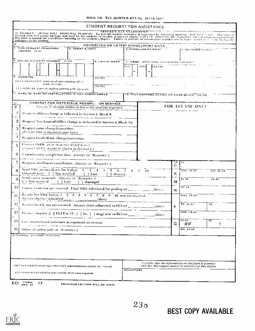
MAIL TO, ECI, GUNTER AFS AL 36118.5643
STUDENT REQUEST FOR ASSISTANCERR1N AC1 Al crATT7TrST1110R1 IV: 10 CSC 11012. PRINCIPAL PURPUSE: To provide student assistance as ceipicsted 4,5 idnidnat students. ROCIr.I `'L I Inshipped svith 1.11 course package. and used by the student. as needed. to Flace it iIIquir "III, I II- I"Ou'sledthis form is needed for expeditious handling of the student's inquiry. Failute Ii nrosiac iii nnotnianon ,soina It sun iii sluste. to nii,fliaeascisialice lo IIIC Student
1 THIS REQUEST CONCERNSCOURSE 11 6/
CORRECTED OR LATEST ENROLLMCNT DATA2. TODAY'S DATC 3, EN ROL LME N T DATE
_5 SOCIAL SECURITY NUMBER (7-15)
Ai,011[11 H(1.1 / N'R/ /, 1.1 tS eisa uf unit training of(i...
wit I Ill ode.
6. GRAE7E/RA-N-81
(33-53)
(54-751II 1 Curn.rit uitilwss with zip only.
t: NAME Or BASE OR INSTALLATION IF NOT SHOWN ABOVE
4 AU COVON
7. NAME (Mr.,/ outial. stw".1,1 uutiot. 2.1,t ,101111
117) 1111)
10. TUST CONTROL OFFICE ZIP CODE/5111711) 133:7391
it. HT:QUEST FOR MATERIALS. RECORL . OR SERVICEX l"ce avouch number in box to ti.,ft of service requested.
1 Request Address change indirated in Section I, Block 8.
2 Rtries! Test Ctintrol Office change as indicated in Section I, Block 10.
3 8.C9t1esI IfaIlle Challge/cOrTectioll.ide Old or Incorrect data here)
5
Request Grade/Rank change/correction.
sAN. ss,,iN here.)(I.,reer S S ,S ,11 lad be y11(1 ,Se e i0 1.)
6 1, \ lelld 1 totIrse completion date. (Justif)- in "Remarks-)1---
7 Re.1111,1 cluroihRellt cancellation. (JI/S/iLl in "Remarks')._.. _ ._ __. _ . ._ .___. ______st.nd vizi: skcco. for V ol( 0 1 2 3 4 5 6 7
4....)tinials %sere: I I Not received I I Lost I I Misused9 scmi ,,iurse materials. (Spccift in "Remarks-)
1 I_
Not received I I Lost I I Damaged__.....
FOR ECI USE ONLY
9 lu
10 comse esmn not yet Ict'ciVed. Fiflal VRE submitted for grading on
1'4
6
VOL 33 35
33.34
33- 35
GR. 36 311
35.40
Ri ,blts for VRE Vol(s) 1 2 3 4 5 6 7 8 9 10 not yet receis ed.heet(s:: submitted
Resalis lot CL not yet received, Answer sheet subBlitted tO ECI on
13 Pt esit., inquiry (I I F.C1 Em 17,I 1 itr, J trisg) sent to ECI on
u instructional assistance as requested on reverse.-
15 Other (1..cplain fully m R emarks")
VOL 33.35
TC 36.37 38
DOE 39-45
33.34
0..0"38
1
MC 39-42
r/1.0 A fi (I'«,/i/lio. ore revcrge)
SnolENTS must hui, their OJT Administrator certify thL record.
ILI. 0111 VI? STIOWNTS rocce certif s. their own requests.I..--SIGNATURE
I certify that the information on this form is accurateand that this request cannot he answered at this station.
ECI OFEOC R 81 1 7 PREVIOUS EDITION WILL BE USED.
236BEST COPY AVAILABLE

REQUEST FOR INSTRUCTOR ASSISTANCENO FE: Qui:loons or COIHtIWflIS relating to the accuracy or currency of subject mattei should he forwarded iinecd to pii-patut:;agency. For an immediate response to these questions, call or write the course author directly, using thy Ati'MV()N numbcraddrcss in the preface of each volume. All other inquiries concerning die course shoold be forwarded to ECI.
MY QUESTION IS:VRE ITEM QUESTIONED:
COURSE NO
VOLUME NO
VRE FORM NO
VRE ITEM NO
ANSWER YOU CHOSE(Lt.:ter)
HAS VRE ANSWER SHEET BEENSUBMITTED FOR GRADING?
L.1 YES LI NO
REFERENCE
rrextual reference for the answer I choseV.1,1 be found as ahown below.)
IN VOLUME NO
ON PAGE NO
IN LI LEFT Ll RIGHT COLUMN
LINES THROUGHREMARKS
ADDITIONAL FORMS 17 available from trainers, OJT and EducationOffices, and ECI. Course workbooks have a Form 17 printed on the last page.
CC1 FORM 1J. DEC 84 (Reverse)
2 3
23132 04 7905
CDC 23132
APPRENTICE STILL PHOTOGRAPHIC SPECIALIST
(AFSC 23132)
Volume 4
Photographic Laboratory Applications
Extension Course InstituteAir Training Command
2

Prepared byMSgt Curtis Mayne
andMSgt Jay Perry
3430th Technical Training GroupUSAF School of Applied Aerospace Sciences (ATC)
Lowry AFB, Colorado 80230
Reviewed byJohn Zimmerman, Education SpecialistExtension Course Institute (ATC/AU)
Gunter AFS, Alabama 36118
PREPARED BY3430TH TECHNICAL TRAINING GROUP
USAF SCHOOL OF APPLIED AEROSPACE SCIENCES (ATC)LOWRY AIR FORCE BASE. COLORADO
EXTENSION COURSE INSTITUTE, GUNTER AIR FORCE STATION, ALABAMA
THIS PUBLICATION HAS BEEN REVIEWED AND APPROVED BY COMPETENT PERSONNEL OF THE PREPARING COMMANDIN ACCORDANCE WITH CURRENT DIRECTIVES ON DOCTRINE, POLICY, ESSENTIALITY, PROPRIETY, AND QUALITY.
2 4
PrefaceTuns FOURTH VOLUME of CDC 23132, Apprentice Still P//otographie Specia/i.st.brings you back into the laboratory. Here, we present to you proper darkroom pro-cedures and techniques. Then we mention some of the ways to correct for those inevit-able mistakes. However, our aim is for you to learn the proper methods so that vouwill not need to use corrective techniques.
In Chapter I. we cover the basics of black-and-white chemistry. All of the cameratechniques in the world are of no value if you mix your solutions improperl.
Chapter 2 deals with the procedures you must use once you have the solutionsproperly mixed and the material placed into it. We present film and developer combi-nations and whilt to do after you get the film wet.
Chapter 3 presents information on making black-and-white prints. Solutions,materials, accessories, etc., are all explained and discussed for vou. Here we presentthe proper methods and then some of the corrective techniques. Pay attention to bothbut strive to use the proper methods,
In Chapter 4, we send you to finishing school. That is, we show you how to put thefinishing touches on your prints.
Chapter 5 introduces you to the exciting world of color photography. Theory, film,proccsing, and finishing are all a part of this woild. We keep to the basics in thischapter except for slide duplication.
The final chapter of this course is called Quality Control. If you take steps to con-trol the quality of your work, you are well on your way to being that accomplishedphotographer we talked about in other volumes.
If you have questions on the accuracy or currency of the subject matter of the text,or recommendations for its improvement, send them to the 3430 Technical TrainingGroup/TTMZS, Lowry AFB, CO 80230, Questions requiring an immediate resolu-tion may be directed to the course authors at Autovon 926-4142 between 0800 and1600 (MST) Monday through Friday. NOTE: Do not use the suggestion program tosubmit corrections for typographical or other errors.
If you have questions on course enrollment or administration, or any of ECI's in-structional aids (Your Key to Career Development, Behavioral Objective Exercises,'Volume Review Exercise, and Course Examination), consult your education officer,training officer, or NCO, as appropriate. If this agent can't answer your questions,send them to EC1, Gunter AFS AL 36118, preferably on ECI Form 17, StudentRequest for Assistance.
This volume is valued at 24 hours (8 points).Material in this volume is technically accurate, adequate, and current as of
January, 1979.
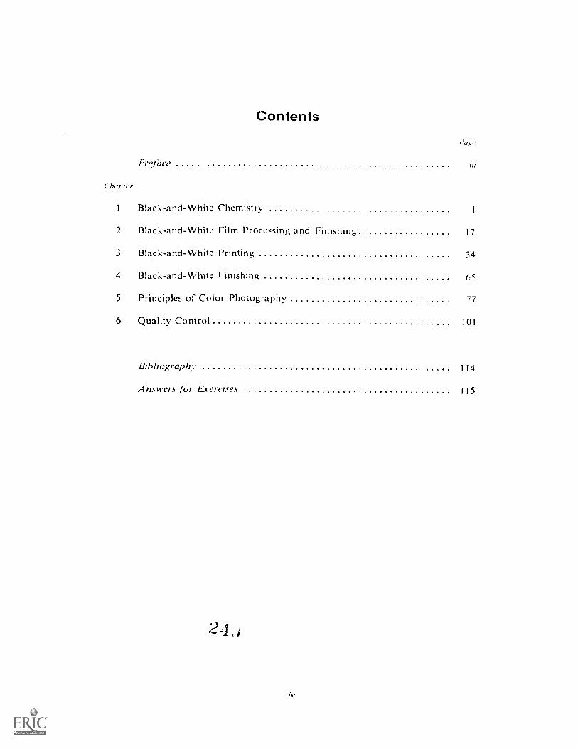
Contents
Chapzer
Preface
Black-and-White Chemistry
Page
III
Black-and-White Film Processing and Finishing 17
3 Black-and-White Printing 34
4 Black-and-White Finishing 65
5 Principles of Color Photography 77
6 Quality Control 101
Bibliography 114
Answers .for Exercises 115
CHAPTER 1
NOTE: In this volume, the subject matter is developed by a series of Learning Objectives. Each of thesecarries a 3-digit number and is in boldface type. Each sets a learning goal for you. The text that followsthe objective gives you the information you need to reach that goal. The exercises following the infor-mation give you a check on your achievement. When you complete them, see if your answers matchthose in the back of this volume. If your response to an exercise is incorrect, review the objective andits text.
Black-and-White Chemistry
THE BASIC FUNCTION of the laboratory portionof the photographic process is to produce negativesand make prints. The conventional method of doingthis is through the use of chemical solutions. The twoprimary solutions used to make black-and-whitenegatives and prints are the developers and the fixers.There are, however, other solutions in the black-and-white process that are used along with developer andfixer to produce a quality image. In this chapter youwill learn the functions of black-and-white chemicalsolutions and specific applications. Also, you willlearn how to properly prepare photographic chemistryand the operation and maintenance of chemicalmixing equipment and mixing facilities.
1-1. Processing SolutionsThere are five basic steps in processing black-and-
white films and papers. These are development.rinsing, fixing, washing, and drying. Let's discuss thefunctions of the chemical steps used to produce theblack-and-white photographic image.
600. State the function of the chemical solutions usedto process black-and-white films and papers.
Developers. The function of a developer is toproduce a silver image which constitutes a photo-graphic negative or print. The process is known aschemical reduction, and it produces an image made upof black metallic silver. Developers do their work in aselective manner, reducing to black metallic silver.only those silver halides that have been exposed totight. Developers differ from one another on how fastthey work and the contrast that they produce. De-velopers can generally be classified by the amount ofcontrast that they are capable of producing. There arelow, medium, and high contrast developers, eachhaving a particular application in photography. Yourchoice of which developer to use can be narrowed
1
down to the type of film you need in taking a photo-graph. Photographic films are also classified by theircontrast capability. There are low-, mcdium-, andhigh-contrast films. You would use a medium-contrastfilm to photgraph a medium-contrast subject and italso follows that a medium-contrast producingdeveloper should be used to process your film, high-contrast film/high-contrast developer, etc.
Film manufacturers recommend the type ofdeveloper to be used with their films, and this informa-tion is contained in the film data sheet packed withthe film. The developers that they recommend arethe ones that give the best overall results.
Another factor that must be considered aboutdevelopers is the negative grain size that they produce.There are fine-grain and moderate-grain developers.Your choice here depends upon the use of the negative.When you need to Ne big enlargements from smallnegatives such as 35mm, a fine-grain film developersuch as Microdol-X or D-76 should be used. Largenegatives such as 4 by 5 inches (10 by 13 cm) can beprocessed in a developer that produces medium grainbecause the degree of enlargement for making printsfrom large negatives is much less than for smallnegatives. So you see. the choice of developer dependsupon many variables such as image contrast. type offilm, and size of prints required.
Stop Bath. Between the development and the fixingsteps, a stop bath also known as a short stop is used.The function of a stop bath is to stop the action of thedeveloper. The most basic stop bath is simply a waterrinse between the developer and fixing steps. This isnot a stop bath in the true sense of the word becausea water rinse cannot completely stop development. Itonly slows it down. A water rinse is usually sufficientwhen you are processing small batches of prints or filmand working at relatively low processing temperatures.A water rinse is used more often when processine filmsthan when processing prints.
24,4
A true stop bath contains an acid, usually aceticacid. The purpose of the acid is to neutralize the alka-linity of thc developer. This stops development be-cause most developers work only in an alkaline state.There are other stop-bath formulas that contain ahardener such as chrome-alum that hardens theemulsion that is swollen and soft after development.This type of stop bath is usually not needed unless youare working at temperatures above 75° F (24° C). Avariation of the chrome-alum stop bath is one knownas an indicator stop bath. Indicator stop baths haveadded to the solution a dye that becomes visible justbefore the stop bath is exhausted so that you canreplace it with a fresh bath. A typical indicator stopbath changes from a light yellow color to deep purplewhen the solution becomes exhausted.
Fixing Bath. The fixing bath is the third step inprocessing black-and-white materials. The fixing bathmakes the image permanent. It does this by dissolvingthe unexposed and undeveloped silver halidesicmain-ing in the film emulsion. It does this without attackingthe metallic silver image. This is important because ifthese unexposed, undeveloped silver halides are notremoved, they will eventually darken and stain, ruin-ing the image. The most basic fixing bath (there aremany) is made up of sodium thiosulfate dissolved inwater. The common name given to this fixing bath isHypo, a term many photographers use for all fixingbaths. Other fixer formulas become more complicatedwith the addition of hardeners such as potassiumalum, buffers such as boric acid to maintain propersolution acidity and prevent sludge, and sodium sulfitethat acts as a preservative. The purpose of theseadditives is to extend the life of the fixing bath.
It really doesn't matter what type of fixing bath youuse. What does matter is that you use the bathproperly and do not allow it to become exhausted.When an exhausted fixing bath is used, no amountof washing can remove the complicated by-productsof fixation from the emulsion. Because of this, manyphoto labs use a two-bath system. The first bath is apartially-used fixing solution, kiiid the second bath isa fresh solution. When the first bath becomes ex-hausteci, the second bath is moved into the firstposition and the exhausted bath is poured into aholding tank for silver recovery. The second tray isthen filled with fresh fixer. This is an economicalmethod that helps to insure that your prints have beenadequately fixed.
Hypo-Clearing Bath. This solution is mildly alka-line in nature and it is used before the material iswashed. Hypo-clearing baths are sometimes referredto as hypo eliminators. This is an erroneous termbecause they don't actually eliminate the fixer. Theiraction essentially is to raise the pH or alkalinity of thefixer within the emulsion. This higher alkalinity causesthe fixer and by products to wash out faster. Hypo-clearing baths are useful because they save water bycutting down on the required wash time. They shouldbe used wherever possible because of the savings in
2
resources. Before treating films or paper in a hypo-clearing bath, rinse the material in water for about oneminutc.
Exercise (600):1. Explain the function of each of the following:
a. Developer.
b. Stop bath,
c. Fixing bath.
d. Hypo-clearing bath.
1-2. Types of Photographic ChemicalsThe preparation of photographic solutions is one
of the most important tasks that you will perform.Accuracy in mixing is a must because without it,photographic quality will suffer. An improperly mixedsolution is not readily recognizable and often the firstindication that it was not properly mixed is when abatch of processed film or paper has been ruined. Inthis section we will discuss the principles of mixingphotographic solutions using bulk chemical whichemploy a photographic formula and the use of pre-packaged chemicals. With the advent of prepackagedchemistry the necessity of mixing solutions from bulkis rapidly becoming a thing of the past.
601. Explain the advantages of using prepackagedchemicals.
Photographic chemicals that are used to prepareprocessing solutions can be obtained from manu-facturers in two forms. These are bulk chemicals andprepackaged chemistry. Prepackaged chemistry is usedmore often. so we discuss this type first.
Prepackaged Chemicals. The majority of yourchemical needs can be met through the use of pre-packaged photographic chemistry.
These are convenience items because the manu-facturer has saved you a lot of trouble by mixing inall the chemical ingredients required to make a solu-tion and placing them into one or two packages. Ineffect, the manufacturer has prepackaged the com-plete formula so that you normally need only to addthe package to the correct volume of water.
There are two basic categories of prepackagedchemistry: formula and proprietary. A prepackaged
2 4
formulaic chemistry k one that can bc -asily dupli-cated from bulk chemistry, the formula used iscommon knowledge that can be extracted from suchpublications as the Photo Lab Index (Morgan andMorgan). Proprietary chemistry is one in which theformula of ingredients of the prepackaged chemistryare the exclusive property of the manufacturer andunknown to the general public. A formulaic chemistry
1)-7? v.iirh rnn hr, pyrrhacrc! in the prepackagedI orm hia ako call be dupbutted by using the publishedformula printed in the Photo Lab Index. Proprietarychemistry. however, can be purchased only in theprepackaged form. As vou can see, there arc really tworeasons for prepackaged chemistry: convenience andprotection of the formula rights for some chemicalsolutions. Kodak's Dektol for example, can be pur-chased only prepackaged and the formula is unpub-lished. Prepackaged chemicals are easy to store,handle, and mix and they provide consistent quality.
Prepackaged chemicals are available to cover allyour photographic needs. You can order preparationsfor developers, stop baths, and fixing baths as well astoners, reducers, intensifiers, and the like. There are anumber of different photo chemical manufacturers,and you will have a wide selection within the contextof the Federal supply system. Always keep in mindthat you should choose chemicals that are compatiblewith the films and papers that you are using.
The preparation of prepackaged chemicals requiresmainly that you follow the directions carefully. Pre-mixed chemicals may be in powder or liquid form.There may be several parts in the package that mustbe mixed in a certain manner. Typically, the contentsof the package are to be mixed with a specific quantityof water. The water must be at the prescribed tempera-ture. The majority of prepackaged chemicals aremixed in warm water, but read the instructions tomake sure. (Remember that the temperature formixing may not be the same as the processing tempera-ture, so you may have to wait for the solution to cool tothe correct temperature for use.) When there is morethan one part, make sure that the parts are added in thecorrect order. Do not be in such a rush that you failto follow directions.
Remember to follow the proper procedures forchemical safety. You should prepare the chemicals ina well-lighted and ventilated room. Do not taste orinhale any chemical. You should wear rubber gloves,apron, and mask for your personal protection.Remember, for safe mixing and quality results, followdirections.
Exercises (601):I. What are the two types of packaged chemicals?
2. State four advantages offered by packagedchemicals.
3. What is the most important rule to keep in mind toinsure consistent results when using packagedchemicals?
4. In what type of environment should packagechemicals be prepared?
602. Explain the reasons for using bulk chemicals andspecify nomenclature, equipment, and proceduresrelated to bulk chemicals.
Bull: Chemicals. An alternative to packaged chemi-cals is preparing your soiutions by using availableformulas (found in the Photo Lab Index, etc.) andbulk (i.e., raw) chemicals. In this section, we shallbriefly cover the use of bulk chemicals.
Mixing solutions by referring to published formulas(in the Photo Lab Index, etc.) and using bulk chemicalscan be advantageous. You can prepare solutions yourarely use (e.g., toners) or those which are not availablein premixed form. You may have to use bulk chemicalsto meet special mission requirements.
Chemical Grades. It is important when usingbulk chemicals that you are aware of the standards ofchemical quality. The United States of AmericaNational Standards Institute (USANSI) publishes aseries of standards covering all of the chemicals usedin photographic processes. These USANSI standardscontain specifications that establish the degree ofpurity and state limiting concentrations for potentiallyharmful impurities that may be present. You canprevent faulty processing caused by the use of chemi-cals of inferior quality by using only a grade ofchemical that meets or exceeds these USANSIstandards.
Chemicals such as sodium sulfite, sodium carbonate,hydroquinone, Metol, etc., that are used in largequantities by the photographic industry, are desig-nated as "Photo Grade" by most suppliers of chemi-cals. This designation means that the chemical sorated meets the USANSI specifications for photo-graphic grade chemicals. "Photo Grade''.or a similardesignation is not, however, one of the standarddesignations of chemical purity commonly used bychemical manufacturers. The quality designationsmost often used are given below with a brief definitionof each.
Primary Standard: A specially manufactured andtested analytical reagent of exceptional purity. Usedexclusively for standardizing laboratory volumetricsolutions and preparing reference standards.
ACS or Reagent Grade: A chemical that fullymeets the requirement of the American Chemical
3
2 4 6

Society for Reagent Grade chemicals. lsed in analyti-cal laboratories for testing awl evaluating otherchemical preparations.
C.P.: Chemic,dly pure grade, generally exceedingU.S.P. or N.F. requirements, but slightly lower oualitythan Reagent Grade.
U.S.P.: A grade meeting the requirements of theUnited States Pharmacopoeia (i.e., medicine).
N.F.: A grade meeting the requirements of themost recent, or designated, issue of the NationalFormulary. (U.S.P. and N.F. Grade chemicals areprimarily for drug use.)
Purified: A grade of higher quality than Tech-nical, often used where there are no official standards.
Technical: A grade suitable for general industrialuse.
Generally speaking, USANS1 photographic gradechemicals arc within the quality range of the U.S.P.,N. F., and Purified grades. C.P. Grade chemicals arealways suitable for photogranhic use but are of ahigher quality (and cost) than is generally required.Reagent Grath and Primary Standard chemicals arevery costly and are much purer than is required forphotographic parposes. Some Technical Gradechenticals are satisfactory for photographic use. Theirlow price and availability make them desirable but, forprecise photo applications, they should be thoroughlyevaluated before use.
Prior to using chemicals of unknown grade, youshould obtain the USANSI specifications for theparticular chemicals in question and perform thelaboratory tests as given in these specifications.Chemicals failing to meet the given purity limitsshould not be used in preparing photographicsolutions.
Bulk Chemical Storage and Procedures. Bulkchemicals should be kept in appropriate dark (amber,etc.) stoppered bottle or jars for proper keeping in acool, dry place away from sensitized materials. Allcontainers should be properly labeled, as manychemicals are poisonous. Maximum safety can beinsured by keeping all the toxic chemicals in a lockedcabinet to which only authorized personnel haveacce..s.
To take advantage of bulk chemicals, you need aproperly stocked chemical mix section. An accuratebalance, graduates, thermometer, and stirring rods area few of the basic items required. Personnel who mixchemicals should be thoroughly trained in properprocedures, including reading a formula, using mixingequipment, and observing proper chemical safetypractices.
You are perhaps tired of being continually remindedabout chemical safety, but it must be stressed overand over again with the hope that you will make it ahabit in your work. Any accident brings hardship toeveryone in the section. To this end, here is anotherreview of basic safety procedures that are particularlyapplicable when you are using bulk chemicals.
4
Never smell a chemical directly from the bottle.Instead, hold the bottle at a distance from your nose,and sniff its contenzs cautiously rather than inhaledirectly.
Never taste a chemical.Handle all chemicals cautiously: many will
produce burns or skin irritation.When mixing a strong acid with water, add the
acid slowly to the water while stirring continuously:otherwise, the solution may boil violently and splatteron your hands and face, causing serious burns.Remember: ,Vever pow. water into acid.
Be sure that the chemical mixing room or area inwhich you are going to mix chemicals is well venti-lated. The fumes or dust from some chemicals can hevery irritating to your nose and eyes, as well as harmfulto photographic sensitized materials.
In all cases, be sure to see a doctor as soon aspossible in the case of an accident.
Exercises (602):I. What arc the advantages of using bulk chemicals?
2. What grade of chemical is normally used in photo-graphic work?
3. Under what circumstances can you use TechnicalGrade chcmicals for photographic work?
4. How should bulk chemicals be stored?
5. What type of facilities do you need in order to usebulk chemicals?
6. How should acid and water be mixed? Why?
1-3. Preparation of Chemical SolutionsIn the Air Force, we use two methods of mixing
chemicals (I) hand mixing and (2) machine mixing.Hand mixing can be used when small quantities of
solutions are needed or when machines are not avail-able. Machine mixing is necessary to handle the largeproduction requirements of most labs. In this sectionwe point out the operation of the A-I mixer, which istypical of the mixing units you will be using.
24'e
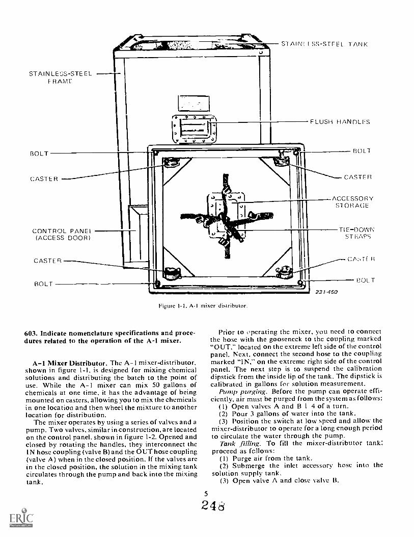
STAINLESS-STE ELRAME
BOLT
CONTROL PANEL(ACCESS DOOR)
CASTE R
BOLT
STAIN f USS-STEEL TANK
FLUSH HANDLES
BOLT
CASTE R
ACCESSORYSTORAGE
Figure I- I. A-I mixer distributor.
603. Indicate nomenclature specifications and proce-dures related to the operation of the A-1 mixer.
A-1 Mixer Distributor. The A-1 mixer-distributor,shown in figure 1-1, is designed for mixing chemicalsolutions and distributing the batch to the point ofuse. While the A-1 mixer can mix 50 gallons ofchemicals at one time, it has the advantage of beingmounted on casters, allowing you to mix the chemicalsin one location and then wheel the mixture to anotherlocation for distribution.
The mixer operates by using a series of valves and apump. Two valves, similar in construction, are locatedon the control panel, shown in figure 1-2. Opened andclosed hy rotating the handles, they interconnect theIN hose coupling (valve B)and the OUT hose coupling(valve A) when in the closed position. If the valves arein the closed position, the solution in the mixing tankcirculates through the pump and back into the mixingtank.
5
TIEDOWNST RAPS
Cf\T1
BOLT
Prior to operating the mixer, you need to connectthe hose with the gooseneck to the coupling marked"OUT," located on the extreme left side of the controlpanel. Next, connect the second hose to the couplingmarked "IN," on the extreme right side of the controlpanel. The next step is to suspend the calibrationdipstick from the inside lip of the tank. The dipstick iscalibrated in gallons for solution measurement.
Pump purging. Before the pump can operate effi-ciently, air must be purged from the system as follows:
(1) Open valves A and B 1 4 of a turn.(2) Pour 3 gallons of water into the tank.(3) Position the switch at low speed and allow the
mixer-distributor to operate for a long enough periodto circulate the water through the pump.
Tank .filling. To fill the mixer-distributor tank:proceed as follows:
(1) Purge air from the tank.(2) Submerge the inlet accessory hose into the
solution supply tank.(3) Open valve A and close valve B.
248
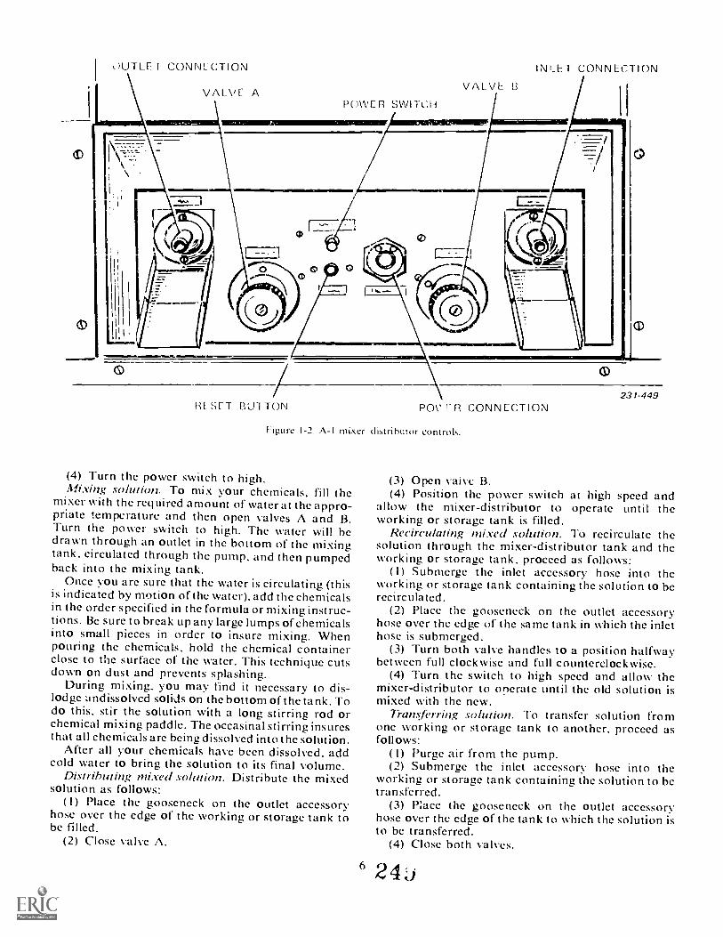
OUTLE T CONNECTION INLET CONNECTION
11
RESFT Mil TON Ti CONNECTION
Figure 1-2. A-I mixer distributor controls.
(4) Turn the power switch to high.Mixing solution. To mix your chemicals, fill the
mixer with the required amount of water at the appro-priate temperature and then open valves A and B.Turn the power switch to high. The water will bedrawn through an outlet in the bottom of the mixingtank, circulated through the pump. and then pumpedback into the mixing tank.
Once ;ou are sure that the water is circulating (thisis indicated by motion of the water), add the chemicalsin the order specified in the formula or mixing instruc-tions. Be sure to break up any large lumps of chemicalsinto small pieces in order to insure mixing. Whenpouring the chemicals, hold the chemical containerclose to the surface of the water. This technique cutsdown on dust and prevents splashing.
During mixing. you mav find it necessary to dis-lodge undissolved solids on the bottom of the tank. Todo this, stir the solution with a long stirring rod orchemical mixing paddle. The occasinal stirring insuresthat all chemicals are being dissolved into the solution.
After all your chemicals have been dissolved, addcold water to bring the solution to its final volume.
Distributing mixed solution. Distribute the mixedsolution as follows:
( I) Place the gooseneck on the outlet accessoryhose over the edge of the working or storage tank tobe filled.
(2) Close valve A.
6
0231-449
(3) Open vaivc B.(4) Position the power switch at high speed and
allow the mixer-distributor to operate until theworking or storage tank is filled.
Recirculating mixed solution. To recirculate thesokition through the mixer-distributor tank and theworking or storage tank, proceed as follows:
( I) Submerge the inlet accessory hose into theworking or storage tank containing the solution to berecirculated.
(2) Place the gooseneck on the outlet accessoryhose over the edge of thc same tank in which the inlethose is submerged.
(3) Turn both valve handles to a position halfwaybetween full clockwise and full counterclockwise.
(4) Turn the switch to high speed and allow themixer-distributor to onerate until the old solution ismixed with the new.
Transferring solution. To transfer solution fromone working or storae tank to another, proceed asfollows:
( I) Purge air from the pump.(2) Submerge the inlet accessory hose into the
working or storage tank containing the solution to betransferred.
(3) P:ace the gooseneck on the outlet accessoryhose over the edge of the tank to which the solution isto be transferred.
(4) Close both valves.
4
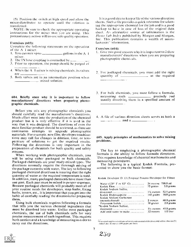
(5) Position the switch at high speed and zillow themixer-distributor to operate until the yolution istransferred.
NOTE: 13e sure to check the appropriate operatinginstructions for the mixer that . ou are using. Thisprecautionary action will insure sale quality operation.
Exercises (O03):Complete the following statements on the operationof the A I mixer.I. You can nnx lip to gallons in the A I
mixer.irhe IN hose coupling is controlled by
3. Prior to operation, the pump should bc purged of
4. When the A I mixer is mixing chemicals. its valvesare
5. Both valves arc in an intermediate position whenmixed solution.
604. Briefly state why it is important to followmanufacturers' directions when preparing photo-graphic chemicals.
Before you mix any photographic chemicals youshould carefully read the manufacturer's directions.Much effort went into the production of the chemicalproduct but it is only effective if it is used in theway that it was designed. The directions of even themost familiar product should be reviewed, as there arecontinuous attempts to upgrade photographicmaterials. For example, new film/ developer combina-tions may call for changes in dilution, time, or tem-perature of solutions to get the required results.Following the directions is very important in thepreparation of chemicals for both quality and safetyreasons.
When working with photographic chemicals, youwill be using eithcr packaged or bulk chemicals.Packaged chemicals are your ready-mixed types. Thedirections normally require the thorough mixing ofthe package contents with water. The key to followingpackaged chemical directions is insuring that the rightquantity of water at the required temperature is used.In addition, many packaged chemicals have more thanone part. Each part must be mixed in proper sequence.Because packaged chemicals will probably meet all ofyour routine needs for developers, stop baths, fixingbaths. toners. etc.. it is important that you get into thehabit of carefully reading the directions for preparingthem.
Using bulk chemicals requires following a formulathat tells you the various chemical ingredients thatmust be dissolved into water. Unlike most packagedchemicals, the use of bulk chemicals calls for veryprecise measurement of each ingredient. This requiresboth caution and a knowledge of measuring in order tocarry out the directions.
7
It is a good idea to keep a file of the various directionsheets. Such a file provides a quick reterence for select-ing the appropriate chemical for the job and is a goodbackup to have in ease of loss of the original datasheet. An alternative source of information is thePhnw lab Index published by Morgan and Morgan,Inc. This publication contains a wealth of manu-facturers' In formation.
Exercises (604):I . I e two good reasons why it is important to ;ollow
manufacturers' directions when you are preparingphotographic chemicals.
2. For packaged chemicals. you must add the rightqua luny of at the required
3. For bulk chemicals. you must follow a formula,measuring each precisely ?ndusually dissolvinLL them in a specified amount of
4. A file of various direction sheets serves as both aand a
605. Apply principles of mathematics to solve mixingproblems.
The key to employing a photographic chemicalformula is the ability to follow formula directicns.This requires knowledge of chemical mathematics andmeasuring procedures.
The following is a typical Kodak Formula, pre-sented to show you the basic format:
Kodak Developer 11,13 (Tropical Process Developer for Films)
Water (125° F or 52° C) 24 ouncet 750.0 mlKodak Elon 75 graMs 5.0 gramsKodak Sodium Sulfite.desiccated 1'4 ounces 52.5 gramsKodak Hydroquinone 145 grains 10.0 gramsKodak Sodium Carbonate(rnonohydrated) 2 ounces 60.0 gramsPotassium Iodide 10 grains 2.0 grams
*Kodak Sodium Sulfate.desiccated 11/2 ounces 45.0 gramsAdd cold water to make 32 ounces 1.0 liter
II it ',preterit:0 to to.e.odturn ,u1I3te er.tal.m.tcad of the de.reeated .ultate. then te.cMIMI, pet 32 nun, 105 gram. per Inert
25u
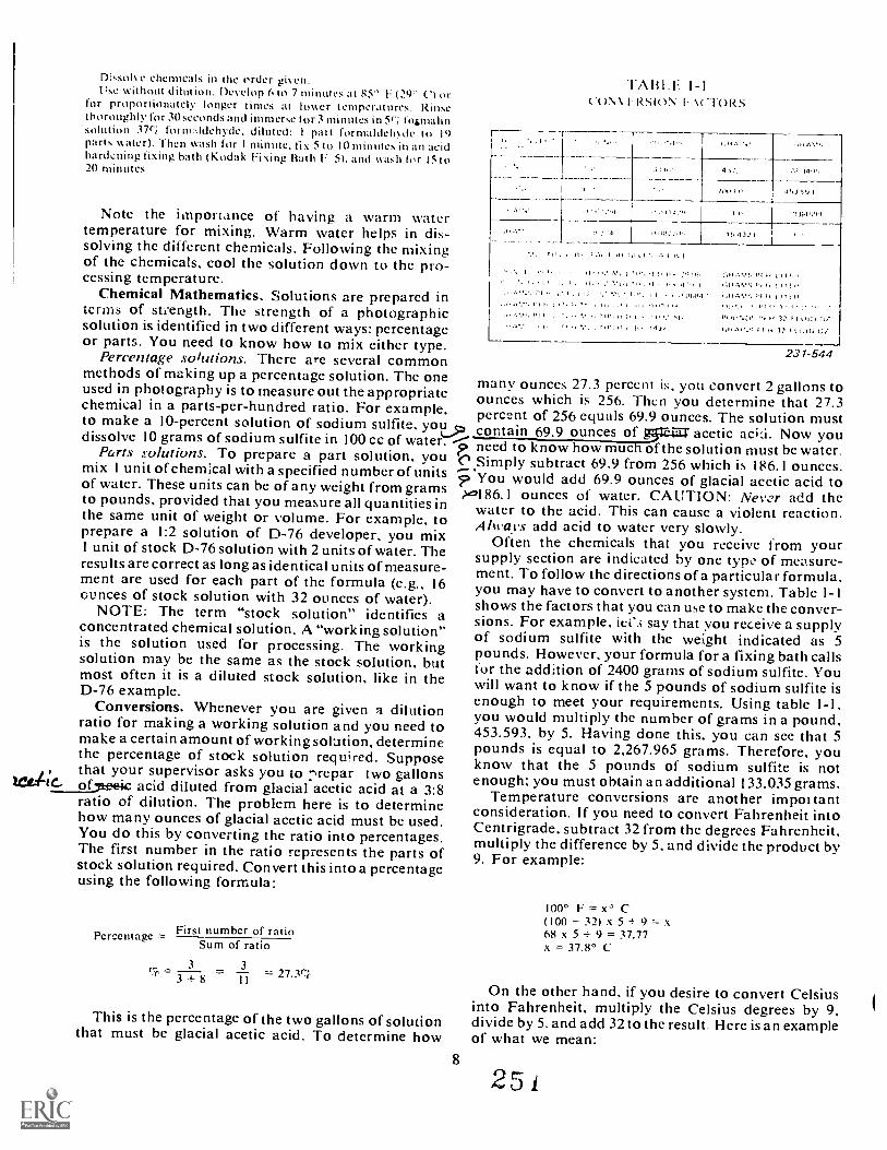
Dissolve chemicals in the order given.Use without dilution. Develop h to 7 minutes at 85' 1: (29 C) or
for proportionately longer times at lower temperatures. Rinsethoroughly for 30 seconds and immerse I or 3 minutes in 5ri fomalinsolution 37(' i forimildehyde, diluted: I part formaldehyde to 19parts \tater). 1 hen wash for I minute. tix 5 to 10 minutes in an acidhard.:ning fixing bath (Kodak Fixing Bath F 5). and wash for 15 to20 minutes.
Note the impoitance of having a warm watertemperature for mixing. Warm water helps in dis-solving the different chemicals. Following the mixing .? 1; 1,1of the chemicals, cool the solution down to the pro-cessing temperature.
Chemical Mathematics. Solutions are prepared interms of suength. The strength of a photographicsolution is identified in two different ways: percentageor parts. You need to know how to mix either type.
Percentage solutions. There are several commonmethods of making up a percentage solution. The one many ounces 27.3 percent is, you convert 2 gallons toused in photography is to measure out the appropriate
ounces which is 256. Then you determine that 27.3chemical in a parts-per-hundred ratio. For example, percent of 256 equals 69.9 ounces. The solution mustto make a 10-percent solution of sodium sulfite, yottl, contain 69.9 ounces of g5re-t= acetic Now youdissolve 10 grams of sodium sulfite in MO cc of water. p need to know how much of the solution must be water.Parts solutions. To prepare a part solution, you C Simply subtract 69.9 from 256 which is 186.1 ounces.mix 1 unit of chemical with a specified number of units ? You would add 69.9 ounces of glacial acetic acid toof water. These units can be of any weight from grams '1.0186.1 ounces of water. CAUTION: Netvr add theto pounds. provided that you measure all quantities inwater to the acid. This can cause a violent reaction .the same unit of weight or volume. For example, to Always add acid to water very slowly.prepare a 1:2 solution of D-76 developer, you mix
Often the chemicals that you receive from your1 unit of stock D-76 solution with 2 units of water. The supply section are indicated by one type of measure-results are correct as long as identical units of measure- ment. To follow the directions of a particular formula,ment are used for each part of the formula (e.g., 16 you may have to convert to another system. Table I- Iounces of stock solution with 32 ounces of water).shows the factors that you can use to make the conver-NOTE: The term "stock solution" identifies a sions. For example, iei'S say that you receive a supplyconcentrated chemical solution. A "working solution" of sodium sulfite with the weight indicated as 5is the solution used for processing. The workingpounds. However, your formula for a fixing bath callssolution may be the same as the stock solution, but for the addition of 2400 grams of sodium sulfite. Youmost often it is a diluted stock solution, like in thewill want to know if the 5 pounds of sodium sulfite isD-76 example.enough to meet your requirements. Using table 1-1,Conversions. Whenever you are given a dilution you would multiply the number of grams in a pound,ratio for making a working solution and you need to 453.593, by 5. Having done this, you can see that 5make a certain amount of working solution, determinepounds is equal to 2,267.965 grams. Therefore, youthe percentage of stock solution required. Suppose know that the 5 pounds of sodium sulfite is notthat your supervisor asks you to :nrepar two gallons
of7teeic acid diluted from glacial acetic acid at a 3:8 enough; you must obtain an additional 133.035 grams.Temperature conversions are another impottantratio of dilution. The problem here is to determine consideration. If you need to convert Fahrenheit intohow many ounces of glacial acetic acid must be used. Centrigrade, subtract 32 from the degrees Fahrenheit.You do this by converting the ratio into percentages. multiply the difference by 5, and divide the product byThe first number in the ratio represents the parts of 9. For example:stock solution required. Convert this into a percentage
using the following formula:
'FABLE I-ICO\ \ RtiR)N I
_14,1.
r,10411, 453 -..11
,,148.1.4
A 1 .11:3
I ..1 1/111, ./ /11, {// 4,1 / I
114 iSIS l' 4 If f 4414511, 5 4 if 1, I,
, 144(4,.4 3:`. . il 14.14 l11:01, N i 1:` N At)
231-544
First number of ratioPercentageSum of ratio
3= 3 + 8 = 3 = 27 VT
I I
100° F = C(100 32) x 5 9 = xfi8 x 5 9 = 37.77x = 37.8° C
On the other hand, if you desire to convert Celsiusinto Fahrenheit, multiply the Celsius degrees by 9.This is the percentage of the two gallons of solution divide by 5, and add 32 to the result. Here is an examplethat must be glacial acetic acid. To determine how of what we mean:
8
2 5 i
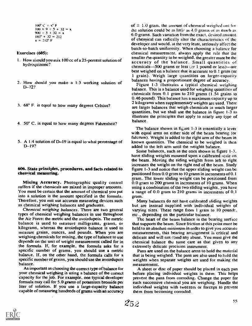
100° C = o F100 x 9 + 5 + 32 = x900 + 5 + 32 =180° + 32 = 212x = 212° F
Exercises (605):
I . How should you mix 100 cc of a 25-percent solution ofhydroquinone?
2. How should you make a 1:3 working solution ofD-72?
3. 68° F. is equal to how many degrees Celsius?
4. 50° C. is equal to how many degrees Fahrenheit?
5. A 1:4 solution of DI9 is equal to what percentage ofD-19?
606. State principles, procedures, and facts related tochemkal measuring.
Mixing Accuracy. Photographic quality controlsuffers if the chemicals are mixed in improper amounts.You must be certain that the amount of chemical you putinto a solution is the amount specified in the formula.Therefore, you mst use accurate measuling devices suchas chemical weighing balances and graduates.
Chemical weighing balances. There are two generaltypes of chemical weighing balances in use throughoutthe Air Force: the metric and the avoirdupois. The metricbalance is used to measure milligrams, grams, orkilograms, whereas the avoirdupois balance is used tomeasure grains, ounces, and pounds. When you areweighing chemicals for mixing, the type of balance to usedepends on the unit of weight measurement called for inthe formula. lf, for example, the formula asks for aspecific number of grams, you should use a metricbalance. lf, on the other hand, the formula calls for aspecific number of grains, you should use the avoirdupoisbalance.
As important as choosing the correct type of balance foryour chemical weighing is using a balance of the correctcapacity for the job. For example, one typical developerformula may call for 5.0 grams of potassium bromide perliter of solution. If you use a large-capacity balancecapable of measuring hundreds of grams with an accuracy
of ± 1.0 gram, the amount of chemical weighed out torthe solution could be as little as 4.0 grams or as much as6.0 grams. Such variation from the exact, desired amountof chemical can radically alter the characteristics of thedeveloper and would, at the very least, seriously affect thebatch-to-batch uniformity. When choosing a balance forchemical measurement, always apply the rule that thesmaller the quantity to be weighed, the greater must be thcaccuracy of the balance. Small quantities ofchemicals-500 grams or less r 1 pound or less)arebest weighed on a balance that is accurate to 0.1 gram (or1 grain). Weigh large quantities on larger-capacitybalances having a proportionate degree of accuracy.
Figure 1-3 illustrates a typical chemical weighingbalance. This is a balance used for weighing quantities ofchemicals from 0.1 gram to 210 grams (1.54 grains to0.46 pound). This balance has a maximum capacity up to2 kilograms when supplementary weights are used. Thereare larger balances that weigh chemicals in much largerquantities, but we shall use the balance in figure 1-3 toillustrate the principles that apply to nearly any type ofbalance.
The balance shown in figure 1-3 is essentially a leverwith equal arms on either side of the beam bearing (orfulcrum). Weight is added to the right arm of the beam inknown quantities. The chemical to be weighed is thenadded to the left arm until the weights balance.
Some balances, such as the ones shown in figure 1-3,have sliding weights mounted upon a calibrated scale onthe beam. Moving the siding weights from left to rightincreases the weight on the right end of the beam. Studyfigure 1-3 and notice that the upper sliding weight can bepositioned from 0.0 gram to 10 grams in increments of 0.1gram. The lower sliding weight can be positioned from0.0 gram to 200 grams in increments of 10 grams. Whenusing a combination of the two sliding weights, you havea range of 0.0 gram to 210 grams in increments of 0.1gram.
Many balances do not have calibrated sliding weightsbut are instead supplied with individual weights ofvarying sizes. These range from 1 gram to 10 pound!: ,
etc., depending on the particular balance.The heart of the beam balance is the bearing surface
that supports the beam. Since friction at this point must beheld to an absolute minimum in order to give you accuratemeasurements, this bearing arrangement is critical anddelicate and will not r.tand any abuse. You must give thechemical balance the same care as that given to anyextremely delicate precision instrument.
Pans are used on the balance arms to hold the materialthat is being weighed. The pans are also used to hold theweights when separate weights are used for making themeasurement.
A sheet or disc of paper should be placed in each panbefore placing individual weights in them. This helpsprevent the pans from corroding. Change the paper foreach successive chemical you are weighing. Handle theindividual weights with tweezers or forceps to preventthem from becoming corroded.
25 4 55

BEAMBALANCE INDICATOR PAN
PANIWO
SLIDINGWEIGHT
231.448
Figure 1-3. Chemical weighing balance.
A balance indicator on the beam balance shows whenthe material that is being weighed and the calibrated,counter-balancing weights aree equal. In the balanceshown in figure 1-3 the indicator consists of a scale andpointer. You may find in other balances that the indicatoris composed of two extensions over the center of thebeam, which are part of the pan supports. A state ofequilibrium is indicated on this type of balance whenthese two extensions are aligned.
The beam balance is equipped with a balanceadjustment or trimming device. This adjustment,consisting of movable weights, can be positioned andlocked to compensate for minor inequalities in theweights of the two ends of the beam that could, if notcorrected, give you erroneous readings.
Photographic graduates. Besides using balances formeasuring dry photographic chemicals, you will also usephotographic graduates for measuring liquids. Forinstance, you would use the graduate for measuring theamount of sulfuric acid to put into a bleach solution.
Graduates are made in varying sizes, calibration, andconstruction mateirial. Figure 1-4 illustrates two commontypes of glass graduates. Although most of the graduatesyou will use are calibrated in the U.S. liquid measurementsystem (drams, ounces, quarts, and gallons), it is notuncommon to find a graduate calibated in the metricliquid measurement system (liters).
Glass is most communly used for making graduatesbecause it is inert to most che als, transparent, andreasonably durable. Graduates are also made from othermaterials, such as plastics. When using graduates of
SLIDINGWEIGHT
plastic, be sure that you do not try to measure strong acidssuch as sulfuric acid, which could cause severe damage.You should also make sure that the material of thegraduates you use does not react with any of yourphotographic chemicals.
To use the graduate, slowly pour into it the liquid to bemeasured. Stop pouring when the surface of the liquidreaches the calibration mark indicating the desiredamount. Major divisions are indicated by numerals on theglass. Subdivisions are indicated by calibration linesonly. You must compute the value of the individualsubdivisions. For example, the marked lines may read inseries of 10. If there is only one calibration line betweeneach graduation of 10, then the calibration line would befor a value of 5.
Exercises (606):
1. the beam balances you are likely to use will probablybe calibrated for what two weighing systems?
2. In terms of accuracy, what is the rule for choosing abalance?
9 a 25,3 57

3. Complete the following statements on the operation ofa beam balance.
a. A beam balance uses eithei orweights.
b. should be plac in eac:. pan toprevent contamination.
c. Inequalities between the two ends of a beam iscorrected by using the device.
58
d. Chemicals to be weighed are placed in thepan.
e. When individual weights are used, they are placedin the pan.
f. Place a in each pan to preventcorrosion to the pans.
g. Handle individual weights with toprevent corrosion to them.
254

3230292624222018--161412108642
CC ORGRAMS
1000900800700600500400300200100
Figure 1-4. Photographic graduates.
4. What should be your main concern when you areconsidering the use of graduates made of differentmaterials?
5. If there are four calibration marks between the 0and 10 marks on a graduate. each calibration markwould stand for how much of an increase?
1-4. Environmental ProtectionEnvironmental pollution is the presence of physical,
chemical, and biological elements that adverselyaffect all living things. Pollution affects human health.alters ecological balances, affects animal and plantlife, and causes deterioration of man-made objects.It includes noise, improper solid waste management,and other things conventionally thought of aspollutants.
Pollution is an economic, technical, and socialproblem. It is a problem because the earth and itsinhabitants have only a limited supply of air and water.When these are gone. or contaminated to the pointwhere they can no longer support life, all living thingson earth, as we know them, will become extinct. Onlyecently have we become aware of the consequences ofwisoning these two life-sustaining substances. Be-'ruse of this awareness, much has been done to lay the
)undwork for legislation to control water and airIlution.The Refuse Act of 1899 requires that a permit be
obtained before virtually any substance other than11
231-448A
sewaae is discharged into most streams, rivers. lakes.or other bodies of water. Failure to do so constitutes acriminal offense. Air Force personnel responsible forviolating this act can be criminally prosecuted.
The Clean Air Act requires Federal installationsto comply with Federal. state, interstate. and localrequirements for the control and abatement of airpollution. This is more than just meeting air qualitystandards. For example. it means that it is necessaryto apply for state permits where activities such asfire-fighting training requires state approval.
In this chapter. we discuss the environmental pro-tection program of the Air Force with particularemphasis on photogranhic facilities. In light of thisgoal, we also discuss reclaiming silver from fixingbaths.
607. From a list of possible environmental practices,identify those Iihich are consistent INith Air Forcepolicy.
As explained in A FR 19 -1, Pollution' Abatementand Environmental Quality. environmental pollutionis the presence of physical, chemical. and biologicalelements or agents that adversely affect human healthor welfare, unfavorably alter ecological balances ofimportance to human life, adversely affect species ofanimal or plant life, cause damage to and deteriorationof manmade materials or property, or degrade theutility of the environment for aesthetic and recreationpurposes. Control of environmental pollution requiresconsideration of air, water, and land. and must extendto noise, improper solid waste management. and
25o
electromagnetic energy. as well as things conven-tionally thought of as pollutants.
The Federal Water Pollution Control Act, theClean Air Act, and other recent Federal legislationrequire that Federal installations comply with Federal,state, and local legislation covering pollution. TheAir Force, therefore, is actively involved in pollutioncontrol.
Air Force environmental policy encompasses thefollowing principles:
a. Eliminate or control environmental pollutantsgenerated by or resulting from Air Force operationsor from contractor operations on real property owned,leased, or controlled by the Air Force consistent withthe overall mission of the Air Force.
h. Lead in preventing, controlling, and abatingenvironmental pollution by accelerating correctivemeasures at Air Force installations, and by initiatingand supporting local area programs of local communi-ties in developing area-pollution abatement programs.
c. Provide preventive pollution control by: (1)reducing or eliminating waste at the point of genera-tion, (2) considering potential environmental pollutioncontrol problems when selecting chemical compoundsand material to be used in Air Force operations, and(3) including pollution abatement as an element inspecifications.
d. Dispose of discharge pollutants in a manner thatwill not, directly or indirectly, expose people to con-centrations of any substance hazardous to health.
e. Insure that contracts for disposal of wastecontain provisions that require the disposal method tobe in accordance with applicable local, state, and/ orFederal criteria and standards.
f Install facilities or establish procedures toprevent heated water from increasing stream tempera-tures above acceptable limits.
g. Install treatment facilities where local facilitiesare not adequate.
h. Insure that all materials (including solid fuels,ashes, petroleum products, and other chemical andbiological agents) are used, stored, and handled toavoid or minimize the possibilities of water and airpollution.
The Role of the Base Photo Lab. The base photolaboratory has an important role in carrying out theAir Force's environmental protection policies. Thedischarge of photographic solutions and waste intothe sewage system poses a problem. A laboratory canpromote safe disposal by making sure that the photo-graphic solutions and waste are well mixed with water.If large amounts must be discharged, as when process-ing machines are drained, it wo :Id be best to collectthe solutions in stand tanks and then control theoutflow.
The photographic laboratory makes a vital contri-bution through the silver recovery program. Theregeneration of silver-laden fixing baths and therecovery of silver from black-and-white films saves avital national resource and reduces the amount ofsilver-laden waste that is discharged.
Exercise (607):I. Which of the following practices are consistent with
Air Force policy?a. Establishment of treatment facilities.b. Pollution disposal methods may violate local
laws.c. Reduction of waste at the point of generation.d. Expose local residents to mercury poisonina.e. The discharge of large amounts of silver from
base photographic operations.
608. Cite the effects, advantages, and disadvantages ofequipment used in silver recovery from fixing solutions.
The annual production of silver in the United Statesaccounts for only 25 percent of the Nation's industrialrequirements. The balance must be obtained throughpurchase from foreign countries. This has an adverseeffect on the Balance of Payments Program. Thephotographic industry uses approximately 43,000,000troy ounces (12 troy ounces to a pound) of silver peryear. The Air Force is a major consumer of photo-graphic products. Therefore, recovery of silver fromexpended photographic material is vital in the interestof national economy, conservation of a criticalmaterial, environmental protection, and alleviationof the gold flow problem.
Silver is available for recovery from two mainsources in the photographic field. One source isvarious exhausted processing solutions. The other isexpended films, papers, and some printed plates.
Fixing baths used in black-and-white and colorprocessing are rich sources of silver. The purpose ofthe fixing bath is to convert unexposed, undevelopedsilver halides to water-soluble compounds tht can beremoved from the emulsion. When black-and-whitefilms are processed, up to 80 percent of the silver inthe emulsion dissolves out and remains in solution inthe fixing bath. The remainder of the silver forms theimage. In color processing, all of the metallic silver inthe film is converted to a silver salt in the bleach and isremoved in the subsequent fixing bath.
Primary Fixers. The primary fixers used in AirForce photographic processing are ammoniun .thiosulfate and sodium thiosulfate, described thus:
a. Ammonium thiosulfate fixers are exhaustedprimarily by dilution. Dilution is caused by chemicalscarried into the bath by the film and, in turn, fixeringredients are carried out. The fixing rate of am-monium thiosulfate is affected very little by the Averconcentration, so continuous recovery of silver doesnot extend its life. The justification for recovery is thesilver itself. Also, with continuous silver recovery, allfilms enter the wash containing very little residualsilver. Since the washing rate is extremely sensitive tothe presence of silver, films with low residual silver
12 2 5 6
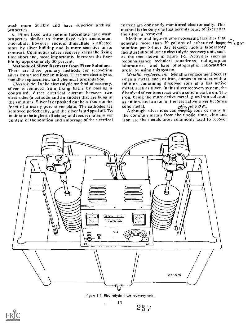
wash more quickly and have superior archivalproperties.
b. Films fixed with sodium thiosulfate have washproperties similar to those fixed with ammoniumthiosulfate; however, sodium thiosulfate is affectedmore by silver buildup and is more sensitive to itsremoval. Continuous silver recovery keeps the fixingtime short and, more importantly, increases the fixerlife by approximately 50 percent.
Methods of Silver Recovery from Fixer Solutions.There are three primary methods for recoveringsilver from used fixer solutions. These are electrolytic,metallic replacement, and chemical precipitation.
Electrolytic. In the electrolytic method of recovery,silver is removed from fixing baths by passing acontrolled, direct electrical current between twoelectrodes (a cathode and an anode) that are hung inthe solutions. Silver is deposited on the cathode in theform of a nearly pure silver plate. The cathodes areremoved periodically, and the silver is stripped off. Tomaintain the highest efficiency and recover rates, silvercontent of the solution and amperage of the electrical
current are constantly monitored electronically. Thismethod is the only one that permits reuse of fixer afterthe silver is removed.
Medium ald high-volume processing facilities thatgenerate more than 30 gallons of exhausted 4%.-nta *1 y.solution per 8-hour day (except mobile laboratoryfacilities) should use an electrolytic recovery unit, suchas the one shown in figure 1-5. Activities such asreconnaissance technical squadrons, radiographiclaboratories, and base photographic laboratoriesprofit by using this system.
Metallic replacement. Metallic replacement occurswhen a metal, such as iron, comes in contact with asolution containing dissolved ions of a less activemetal, such as silver. In this silver recovery system, thedissolved silver ions react with a solid metal, iron. Theiron, being the more active metal, goes into solutionas an ion, and an ion of the less active silver becomessolid metal. dIspla.ce,
Although silver ions can 6+Et4. ions of many ofthe common metals from their solid state, zinc andiron are the metals most commonly used to recover
Figure 1-5. Electrolytic silver recovery unit.
13
25 /

silver from fixing baths. Because of its economy and The cartridge is easy li use and effective. Fixingconvenience, steel wool is the most often used. -(4,1.0 solutiors, through the cartridge and the silver
The acidity of the fix is an important factor when collects on the steel wool. After it becomes laden withyou use steel wool to recover silver. Iron dissolves silver, t-Immtstil=g1=1:033:1=2=12e=eittailiteciincitIr4reisit.readily in acid solutions, and once it is dissolved, it no The metallic replacement system is ideal for lowlonger reacts with silver ions. Too strong an acid volume photographic facilities that generate fewersolution, therefore, results in the loss of some of the than 30 gallons of exhausted solution per 8-hourszeel wool. However, some dissolution of the iron bf (8'Clay. Mese activities inclu e medical and dental X-raythe acid fix is desirable because the etching action of laboratories, photographic hobby shops, and smallthe acid exposes new surface area to the solution, base photographic laboratories. All mobile facilitiesMoreover, excess alkalinity slows the replacement can be served by this system.reaction. C'hemical precipitation. By adding certain chemicals
Fortunately, the pH of most fixes is within the range such as sodium hydroxide to the solution, silver isfor good utilization of steel wool. Below a pH of 4, the precipitated from the fixing bath in the orm of sludgedissolution of the steel wool is too rapid. Above a pH that is dried and refined to reclaim the silver. Theof 6, the replacement reaction is so slow that an exces- fixing solution must be discarded after using thissive amount of silver may be lost due to the long method. This method is not recommended for Airreaction time required to recover the silver. Force use due to facility and manpower requirements
After removal of the silver by metallic replacement, and because of the noxious fumes and odors itthe spent fixing bath must be discarded. This effluent generates.is highly contaminated with iron and has no furtherphotographic use.
Since the advent of the silver recovery cartridge, Exercises (608):shown in figure 1-6, the metallic replacement method I. Explain the effect that silver recovery has on theof reclaiming silver has gained widespread acceptance. two types of fixing baths used in the Air Force.
CoPt
C.
Line from Processor
1:11
Connection to Drain
Figure 1-6. Silver recovery cartridge.
142 5
231-517
Space for Flow of Solution
Ikon Filter
Plastic Screen
IVoid to hold Silver Sludge
2. What is the advantage of the electrolytic method ofsilver recovery?
3. Under what conditions is the metallic replacementmethod ideal?
4. What are the drawbacks in the chemical precipita-tion method?
609. Specify the methods that can be used to recoversilver from black-and-white film.
Methods of Silver Recovery from Black-and-WhiteFilm. There are currently two methods for recoveringsilver from processed and unprocessed film and paperremnants. These are:
Incineration. In this method, the film is reduced toash under controlled conditions. The material isplaced in a burner to control temperature not toexceed 1,700° Fahrenheit (934° C) since highertemperatures bring about vaporization of the silver.To comply with pollution abatement standards,control of emission is also essential. After it is re-covered, the ash is further refined by smelting.
Emulsion stripping. Film strippers are designed toremove the residual silver from photographic negative,sheet, or'rollfilm base. The strippers utilize a chemicalsolution which converts the silver in the emulsion backto a halide state. This method is generally consideredmore expensive than reducing the film to ash, but ithas the advantage of conserving the film base forreuse or sale.
Exercise (609):I. What two methods are used to recover silver from
black-and-white film?
1-5. Operator MaintenanceThe chemical mixing area of your photo lab is a lot
like a kitchen. A kitchen is where all the food is pre-pared for the hungry people. The chemical mixing area
where nearly all of the processing solutions are,reparecl. They both must be kept neat and clean andall of the utensils must be kept in working order.
610. Specify procedural characteristics related tochemical mixing area operator maintenance.
Just like a kitchen, the chemical mixing arca shouldhave certain areas that are for specific jobs. such asmixing, measuring, and storage.
Storage. When you store chemistry, there arccommon sense guidelines to follow. Bulk and pack-aged chemicals should be stored on shelves or incabinets. Place the heavy items on low shelves andthe light, less bulky items on the higher shelves.Hazardous and caustic chemicals should also bestored on the lower shelves in a locked cabinet.
All of the stored solutions should he marked so thateveryone knows what is in each container. You maymark each storage area also so that you do not storefixers with the developers.
Each mixing utensil should also have a properstorage place. Whether it is an A-1 mixer, a funnel, ora stirring rod, each mixing item should be kept in itsown place. Clean each item before you put it away.
Measuring. Just like a cook who uses a measuringcup, you will use a graduate to measure quantities ofsolutions. You may also have to measure and weighdry chemicals. Chemical weighing balances are pre-cision devices and must be protected from damage.They should be kept on a clutter-free work surface, andonce positionej they should be left in place. When youare not using the balance, cover it with its plastic cover.The individual weights used with the balance shouldbe handled with care also. Do not drop them. The verysmallest weights should be handled with tongs orgloved hands to prevent fingerprint corrosion.
Graduates should be cleaned and properly stored.Glass graduates can be cracked or chipped. Therefore,check that yours are not broken. A small piece of glassin the developer may scratch the film or, worse yet, cutyour finger. Plastic graduates and containers will notbreak but sometimes they will stretch. A plasticgraduate that is stretched out of shape will not allowyou to make accurate measurements.
You will probably have thermometers in thechemical mixing area. These. too, occasionally needto be checked. One very accurate thermometer shouldbe kept aside and used only for checking the accuracyof the other thermometers. You may find a thermo-meter which has a separated mercury. If this is thecase, you can usually fix it by carefully heating thebulb. When the separation has expanded into the topof the glass tube, remove the heat. This operation willgenerally reunite all of the mercury.
Use thermometers to measure temperature. Do notuse them for stirring rods or bottle openers.
Mixing. Keep the mixing area clean. A spilledsolution should be wiped up immediately. A wet spoton the floor could become a very slippery spot.
You may have a chemical mixing unit such as theA-1 Mixer/ Distributer. Before you plug in yourmixer, be sure there are no loose or frayed electricalconnections and cords. Be sure your hands are dry andyou are not standing in a wet spot before you plugin the mixer.
Assuming you did not get fried when you plugged inthe mixer, your next step is to rinse it out before you
Is
2 5
start mixing fresh chemistry. This will allow you to seeif it is working properly and ensure the unit is clean.Run the unit in the mix and transfer modes. Drain itand begin to mix your chemistry. When you are done,rinse it again, using the mix and transfer modes oncemore.
Clean the external parts of the mixer with a spongeand water. Do not scrub stainless steel parts withabrasives or scouring powder. This may cause thestainless steel parts to rust.
Holding tanks should have tight-fitting covers, andthe covers should be in place at all timcs to preventoxidation and contamination of the solutions.
As you can tell, operator maintenance in thechemical mixing room is generally common sense andcleanliness.
Exercise (610):I. Complete the following statements by supplying
the missing term or phrase.a. When you store packaged chemistry, you should
store the items on the lower shelves.b. Hazardous or caustic chemicals should be
stored in a cabinet.c. Once a balance has been positioned, it should be
0 1 /
16
d. You can usually repair a thermometer with aseparated mercury by the bulb.
e. Before you plug in a mixer, be sure yourare
f. To flush out a mixer you should till it withand then run it in the
and modes.Tight-fitting co \ ,rs on holding tanks willprevent and
g.
CHAPTER 2
Black-and-White Film Processing and Finishing
AS AN AIR FORCE photographer, you must realizethat the composing and exposing of a scene is no as-surance of a top-notch photograph. The quality of thefinished print is dependent to a great extent on thequality of your darkroom work. A perfectly exposednegative is useless if it is fogged, scratched, or reticu-lated during processing. It is, therefore, very im-portant that you master film processing and finishing.
Every step in the photographic cycle is impo7tant.We don't intend for you to become a "fixer." We wantyou to become an accomplished photographer andfilm finisher. Although we do present methods of per-fecting your product with after-the-fact finishingtechniques. we really intend for you to produce a goodproduct on your first try.
In this chapter. we present the information that willlead you toward becoming that accomplished photog-rapher.
2-1. Film and Developer CombinationsBurns and Allen. Lewis ard Clark, salt and pepper;
them: arc all well-known combinations. Tri- X andDK -50, 35mm Plus X and Acufine should also befamiliar to you. These are film and developer com-binations.
You must know which films and developers arecompatible because the type of film and developer youuse will have an effect on your final product. Improperselection of developer and film will produee unde-sirable results. In this section we present the things youneed to consider when selecting film and developercombinations.
611. Given film, developer, and descriptive uses, deter-mine which combinations would produce acceptableresults.
There are many different types of developers avail-able. Each of them is drsied to produce specificresults. Your problem in c:loosing a developer is topick one that produces a 'qisfactory image; one thatretains most of the values and cont.-ast of the originalscene without the appearance of grain.
Developers for panchromatic film can be classifiedby the way that they affect the inherent grain size attic
17
film being processed. Some developers affect grain sizemore than others. Ihere are general purpose de-velopers that produce medium grain. Fine grain andultra-fine grain developers are also available. Thewhole idea is for you to match the developer to thefilm.
You can pi oduce a negative with reasonable grainsize by using 'a general purpose developer such as DK50. Finer grain images can be achieved by using thesame film and processing it in a fine graindeveloper.The problem here ;s that you will lose some contrast.
The size of the grain becomes important when itcan be seen and is objectionable. The unaided eyeusually cannot see grain in a negative. It is only when aprojection print is made from the negative that thegrain can be seen. A grainy negative produces a "peb-bly" look to the printed image. Grainy prints are al-most always objectionable and should be avoided.
The size print that must be made from a negativedecides whether grain will become apparent in theprint. Small negatives must be enlarged much morethan large negatives to make the same size print. Ifyouhad two negatives of the same scene, one 4 X 5 (10 X 13cm) and one 35mm that were processed in a generalpurpose developer. there would be an obvious dif-ference in an I I X 14 inch (28 X 36cm) print. The smallnegative would produce much more grain than thelarge negative. 1 his is because the small negative mustbe enlarged more than tbe large negative to make thesame size print. When you enlarge the image. you alsoenla rge t he grain.
The best way to assure a line grain negative is to usea fine grain film, and subsequently process it in a tinegrain developer.
Fast films have inherently larger grain and lowercontrast than slow speed films. It should be remem-bered that film developers cannot reduce the inherentgrain size of anv film. Thev can only prevent the grainsize from becoming appreciably larger. Fine graindevelopers do nct enlarge grain size as much as generalpurpose developers.
When you prepare for an assignment, consider tilt':size of the prints that vou must make from the nega-tives and then select the film and developer accord-ingly. As a general rule, process 120 and smaller nega-tives in fine grain developers; process negatives largerthan 120 in general purpose developers.
261

'Fable 2-1 lists some films, developers, and theirpurposes. Although not by any means complete, thistable should give you some good starting points andgeneral guidelines in film and developer selection.
Exercises (611):In terms of constrast and tone values, describe anacceptable negative.
2. When is g:-ain size most noticeable?
3. Why does an enlargement from a small negative ap-pear to be grainy?
4. Which of the following statements arc true?a. 4 x 5 negatives processed in D -19 will have high
contrast.
h. 35mm negatives processed in Aeufine will havefine grain.
c. Process large negatives in D 76 to get high con-trast.
d. Ultra-fine grain can be achied in small nega-tives by processing them in Autofine developer.
refi.efu-1rw+p4+se=4.14.v.c.l.afat.z.r-
2-2. Film ProcessingMost of the film processing done by base photo labs
is manual film processing. Machine processors areavailable but arc only used by labs that do a very largevolume of work. Hand processing is a very satisfactorymethod of processing film, provided you use stand-ardized techniques and the utmost care in handling thefilm.
612. Distinguish between the different types of filmprocessing procedures.
18
As illustrated in figure 2-1, you are likely to en-counter a number of different types of films to process,Except for Polaroid, which has a "built-in" proces-sing system, you should be able to hand process all ofthe other kinds. Film is classified into two broad types:sheet film (individual cut pieces of film) and roll film.Let us now briefly look at how these types of film arcprocessed.
Sheet (('ut) Film. Sheet films may be processed ineither trays or tanks. Although tray processing issatisfactory, it is recommended for only smallamounts of film. Normally, tank processing is moreuniform for large numbers of sheets. With thismethod, each sheet of film is retained in a hanger,which is placed into a tank. Regardless of the methodused, great care in handling is necessary in order toprevent scratches and to insure even processing fromsheet to sheet.
Roll Film. Roll film is processed by using spiralreels and tanks. The film is wound onto a spiral reel.The reel is then placed into a tank for processing. Thekey to getting started is winding the film onto the reelin the proper manner.
Exercises (612):What is the preferred method of processing largeamounts of sheet film?
7. How is roll film processed?
613. State principles. procedures. and nomenclatureassociated with safelights.
Safelights for Film Processing. Now that we arestarting to get into darkroom operation it is im-portant to understand the purpose of safelights. It maycome as a surprise to you that not all darkrooms are"dark." Depending upon the material that is beinghandled, it may be possible to have lights on. Theselights ar.: called safelights.
The function of a safelight is to transmit thc maxi-mum amount of tight that can he used safely withoutdamage to the sensitized materials being handled.Sinec the color sensitivity of different photographicmaterials varies. the color and intensity of the lightmust vary accordingly to be safe. Therefore. a photo-graphic laboratory safelight is a combination of arated light source and the designated filter to protect aspecific sensitized material.
-nu: following safelight filters are the ones mostcommonly use during black-and-white film proces-sing (the numbers are Kodak Wratten designations):
2 6
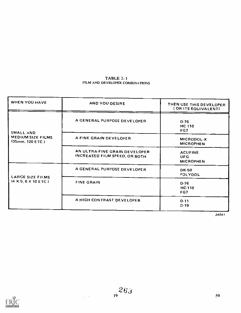
TABLE 2-1FILM AND DEVELOPER COMBINATIONS
WHEN YOU HAVE AND YOU DESIRE
..-
THEN USE THIS DEVELOPER( OR ITS EQUIVALENT)
SMALL ANDMEDIUM SIZE FILMS(35mm, 120 ETC.)
A GENERAL PURPOSE DEVELOPER
?
0-76HC 110FG7
A FINE GRAIN DEVELOPER MICRODOL-XMICROPHEN
AN ULTRA-FINE GRAIN DEVELOPERINCREASED FILM SPEED, OR BOTH
ACUFINEUFGMICROPHEN
LARGE SIZE FILMS14 X 5. 8 X 10 ETC.)
A GENERAL PURPOSE DEVELOPER DK50POLYDOL
FINE GRAIN D-76HC-110FG7
A HIGH CONTRAST DEVELOPER D-11D19 -
26a19
24041
59
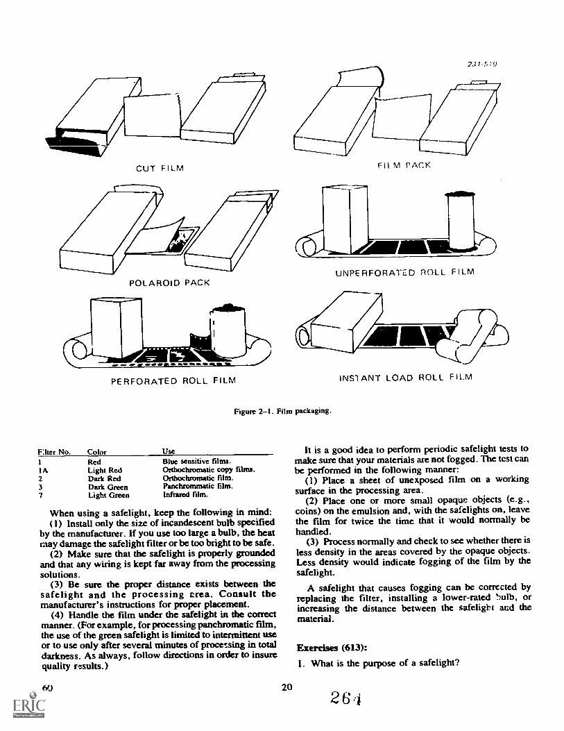
CUT FILM Fll M PACK
POLAROID PACK
.0. .11
PERFORATED ROLL FILM
Flier No. Color1 RedIA Light Red2 Dark Red3 Dark Green7 Light Green
UNPERFORATED ROLL F I LM
Figure 2-1. Film packaging.
UseBlue sensitive films.Orthochromatic copy films.Odhochromatic film.Panchrommatic film.Infrared film.
When using a safelight, keep the following in mind:(1) Install only the size of incandescent bulb specified
by the manufacturer. If you use too large a bulb, the heatmay damage the safelight filter or be too bright to be safe.
(2) Make sure that the safelight is properly groundedand that any wiring is kept far away from the processingsolutions.
(3) Be sure the proper distance exists between thesafelight and the processing area. Consult themanufacturer's instructions for proper placement.
(4) Handle the film under the safelight in the correctmanner. (For example, for processing panchromatic film,the use of the green safelight is limited to intermittent useor to use only after several minutes of processing in totaldarkness. As always, follow directions in order to insurequality results.)
60 20
INS1ANT LOAD ROLL F ILM
It is a good idea to perform periodic safelight tests tomake sure that your materials are not fogged. The test canbe performed in the following manner:
(1) Place a sheet of unexposed film on a workingsurface in the processing area.
(2) Place one or more small opaqm objects (e.g.,coins) on the emulsion and, with the safelights on, leavethe film for twice the time that it would normally behandled.
(3) Process normally and check to see whether there isless density in the areas covered by the opaque objects.Less density would indicate fogging of the film by thesafelight.
A safelight that causes fogging can be corrected byreplacing the fiher, installing a lower-rated .",u1b, orincreasing the distance between the safelight ard themateriai.
Exercises (613):
1. What is the purpose of a safelight?
264
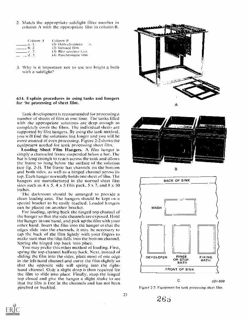
2. Match the appropriat.: safelight filter number incolumn A with the iippropriate fihn in column B.
'oltrmti .Ia I
h 1
7
3.
(.()Iumn II(I) Orthoehromatic12) Infrared (tim.(3) Blue sensitive(4) Panchromatic hum.
3. Why is it important not to use too bright a bulbwit h a safelight?
614. Explain procedures in using tanks and hangersfor 'he processing of sheet film.
'lank development is recommended for processing anumber of sheets of film at one time..ihe tanks filledwith the appropriate solutions arc deep enough tocompletely cover the films. The individual sheets aresupported by film hangers. By using the tank method,you will find the solutions last longer and you will bemore assured of even processing. Figure 2-2 shows theequipment needed for tank processing sheet film.
Loading Sheet Film Hangers. A film hanger issimply a channeled frame suspended below a bar. Thebar is long enough to reach across the tank and allowsthe frame to hang below the surface of the solution(sec fig. 2-3). The frame has channels on the bottomand both sides, as well as a hinged channel across itstop. Each hanger normally holds one sheet of film. Thehangers are manufactured in the normal sheet filmsizes such as 4 x 5. 4 x 5 film pack, 5 x 7. and 8 x 10inches.
The darkroom should be arranged to provide aclean loading area. The hangers should be kept on aspecial bracket to be easily reached. Loaded hangerscan be placed on another bracket.
For loading, spring back the hinged top channel ofthe hanger so that the side channels are exposed. Holdthe hanger in one hand, and pick up the film with yourother hand. Insert the film into the hanger so that theedges slide into the channels, it ma:v be necessary totap the back of the film lightly with your fingers tomake sure that t he. film falls into the bottom channel.Spring the hinged top back into place.
You may prefer this other method of loading. First,spring the top channel halfway back. Next, instead ofsliding the film into the sides, place most of one edgein the left-hand channel and curve the film slightly sothat the opposite side will spring into the right-hand channel. Ouly a slight drop is then required forthe film to slide into place. Finally, snap the hingedtop closed and give the hanger a slight shake to seethat the film is free in the channels and has not beenpinched or buckled.
21
A
A-Z,Viltrie
BACK OF SINK
WASH 11
DEVELOPER RINSE FIXINGOR STOP BATH
BATH
FRONT OF SINK
231-520
Figure 2-2. rquipment for tank processing sheet film.

Developing Sheet Film. Once the hangers areloaded with film, lift all of them by t heir crossbars andlower them into the developer simultaneously with thestarting of the timer. This procedure insures uniformagitation and even development. The immersionshould be done slowly and smoothly to prevent splash-ing and the formation of air bells.
Once the hangers are in the developer, strike themsharply against the sides of the tank to dislodge any airbells that may have formed. Leave the hangers undis-turbed for I minute, and then agitate all of the hangersfor 10 seconds, following the pattern illustrated infigure 2-3. Continue the agitation pattern of 10seconds per minute for the remainder of the develop-ment time.
At about 10 seconds prior to the completion of toedevelopment time, lift the hangers out of the tank andallow them to drain. Then transfer the hangers intothe stop bath and agitate them continuously for about30 seconds. Drain them and then transfer them intothe fixing tank. Continuously agitate them in the fix-ing bath for the first 2 minutes and then continueagitating on a 10 seconds-per-minute basis for theremaining fixing time. Drain the film again and trans-fer the hangers to a water rinse, agitating them forabout one minutelifting and draining them duringthe last 10 seconds. Transfer the hangers to the hypoclearing bath and agitate for tne first 30 seconds thenleave the film in the clearing agent for a total of twominutes.
Drain the sheets again and transfer them to the washtank. When washing is completed, remove the hangersfrom the wash tank and immerse them in a film wettingagent. Film wetting agents reduce the surface tensionof water so that when the film is hung up to dry thewater drains off the film surface without beading up.This prevents the occurrence of water spots on thedried film. No agitation is required in the wettingagent and the film can be removed after one minute.Remove each sheet of film from its hanger and hangthe film up to dry.
Exercises (614):I. Why is tank and hanger processing of sheet film
bettei than tray processing?
2. How does a film hanger work?
3. In what manner should the hangers be immersed inthe developing tank? Why?
4. Briefly explain the pattern for agitating film.
S. What chemical solution is the film immersed inafter fixing?
615. Explain procedures used in the reel and tankprocessing of roll film.
Developing Roll Film. I t is far more convenient andreliable to develop roll film in a small tank than in atray. The design, detail, and construction differs some-what among the various manufacturers' models oftanks, resulting in differences in loading and use.Generally, the basic unit, as illi,trated in figure 2-4,consists of a spiraled and grooved reel to hold thefilm, a tank with a light-tight cover, and a filler cap.Each reel is constructed for a specific size roll of film.The tank top permits pouring the chemicals in and c u tin the light. Normally, all the parts are made out ofstainless-steel or plastic.
rhe proper loading of the film reel in total darknessis one of the most important steps and a challenge tothe beginner. First, make sure that both the reel andyour hands are clean and dry before loading. "Fhen re-ni ove the film from the cassette (35mm or 70mm) orseparate it from the paper backing (120 or 220). "Thefilm must be handled by its edges in order to preventfingerprinting and scratches. (When working with35mm, the tongue oft he leader must be cut off to makea square end prior to loading.) Next, attach the film tothe core of the reel, with the emulsion facing inward.Turn the reel while applying a gentle pressure with thethumb and forefinger on the edges of the film. Thispressure will produce a slight curl in the film and al-low it to pass between the grooves of the rcel. Applyenough tension to the film so that it ,vill not skipgrooves. However, excessive tension can cause the filmto overlap in the grooves. (This skill is best practicedin the light a few times with dummy film.)
Once you have the reels loaded properly, you canthink about processing. Although all tanks have pro-visions for pouring in the solutions after the film isinside, it is best to have the tank already filled withdeveloper. 'Fhis prior preparation insures more evendevelopment. Start the timer, place the loaded reel inthe tank, put on the top and cap, and then brisklyagitate for a few seconds to break any trapped air bells.(Once the top is on, the remaining steps evil he done inthe light.) You then continue processing for the re-quired time with the correct agitation.
During the last 10 seconds of the developing time,the solution can he poured out of the tank through thelight-trapped pouring hole. Fill the tank with water or
22 _
2 6 6
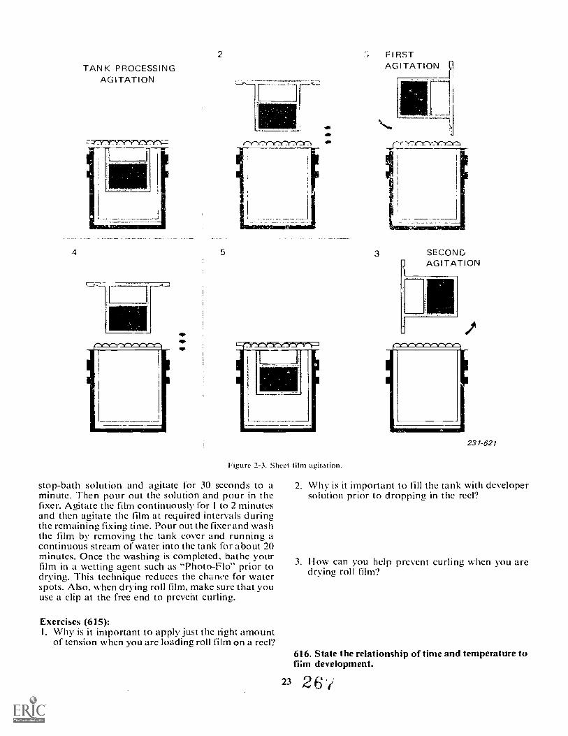
TAN K PROCESSINGAGITATION
2 Fl RSTAGITATION 1.
4 5
C3n"'74!E7"I
\Nos
ry "Yl7f717Thr.7Y7Y*sr-
Figure 2-3. Sheet film agitation.
stop-bath solution and agitate for 30 seconds to aminute. Then pour out the solution and pour in thefixer. Agitate the film continuously for 1 to 2 minutesand then agitate the film at required intervals duringthe remaining fixing time. Pour out the fixer and washthe film by removing the tank cover and running acontinuous stream of water into the tank for about 20minutes. Once the washing is completed. bathe yourfilm in a wetting agent such as "Photo-Flo" prior todrying. This technique reduces the chance for waterspots. Also, when drying roll film, make sure that youuse a clip at the free end to prevent curling.
Exercises (615):I. Why is it important to apply just the right amount
of tension when you are loading roll film on a reel?
3 SECONDAGITATION
23 1-52 1
2. Why is it important to fill the tank with developersolution prior to dropping in the reel?
3. How can you help prevent curling when you aredrying roll film?
616. State the relationship of time and temperature tofiim development.
23 2 6
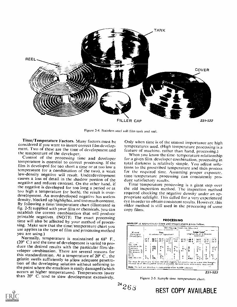
Figure 2-4. Stainless s
Time/Temperature Factors. Many factors must beconsidered if you want to insure correct film develop-ment. Two of these are the time of development andthe temperature of the developer.
Control of the processing time and developertemperature is essential to correct processing. If thefilm is developed for too short a time or at too low atemperature (or a combination of the two), a weaklow-density negative will result. Underdevelopmentcauses a loss of detail in the shadow portion of thenegative and reduces contrast. On the other hand, ifthe negative is developed for too long a period or attoo high a temperature (or both), the result is over-development. An overdeveloped negative has uselessdensity, blocked up highlights, and too much contrast.By following a time/temperature chart (illustrated infig. 2-5) supplied with your film or chemicals. you canestablish the correct combination that will produceprintable negatives. (NOTE: The exact processingtime will also be affected by your method of proces-sing. Make sure that the time/temperature chart youuse applies to the type of film and processing methodyou are using.)
Normally, temperature is maintained at 68° F.,(20° C.) and the time of development is varied to pro-duce the desired results with the particular film/de-veloper combination. There are several reasons forthis standardization. At a temperature of 20° C.. thegelatin swells sufficiently to allow adequate penetra-tion of the developing solution without softening tothe point where the emulsion is easily damaged (whichoccurs at higher temperatures). Temperatures lowerthan 20° C. tend to slow development excessively.
TANK
FILLER CAP
teel roll film tank and reel.
COVER
231-522
Only when time is of the utmost importance are hightemperatures used. (High temperature processMg is afeature of machine, rather than hand, processing.)
When you know the time:temperature relationshipfor a given film developer combination, processing intotal darkness is relatively simple. You adjust solu-tions to the prescribed temperature and thcn processfor the required time. Assuming proper exposure.time/temperature processing can consistently pro-duce satisfactory results.
Time/temperature processing is a giant step overthe old inspection method. "1-he inspection methodrequired checking the negative density under an ap-propriate safelight. This called for a very experiencedeye in order to obtain consistent results. However, thisolder method is still used in the processing of somecopy films.
PROCESSINGDEVELOP at approxirnst. times and temperaturrs given below.
Developing I Ones (in Minot's,
IN:putAir.kageil
1)evrlopersIt'ontilitioip
65 F i es r
Trani:Agitation)
ro I '21 C
72 I,22 C
I
i
75 V I 65 F.24C i 1g C
i
---Largo Tinnli
(.\ rotatIn aiot 1intitrnterval
es F l 70 V30 C , /I C
-----M1
7/ I,22 C
--
7s V24 C
II(. 110(1)11uthol Hi 5 I VA 4.. 4 4.2 i 7 6 C.2 5 4.1tPoLt..t. r, 51/4 5 4.1 4 , 8.2 7 614 6 5'4NIt,11.1,ol. X 9 7 6 5.1 4.2 i 11 0 8 7 elMP Fiona. :(I Ai t Q 14 1.1 12D.7 n s 0. 4 ! 8 7 6.4 6 5t)K MI11 II 1% Ai, . A 5 i 4%1 4..1 4t 5.,1It 'nay he net...ism). to tr to the film %lightly I r provr...ing in vono. him hangrr,shoii beCao.e got,: um/or:Milo thay le.111
. .
containing ',Over halide solvents.
2 42- 6' 6-
231-523
Figure 2-5. Sample time temperature chart
REST COPY AVAILABLE
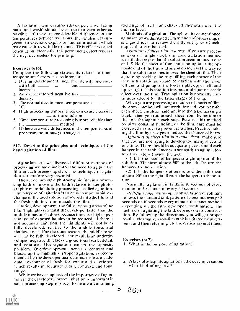
All solution temperatures (developer, rinse. fi.xingbath, and wash) should be as near to each other aspossible. If there is considerable difference in thetemperatures between solutions, the emulsion is sub-jected to excessive expansion and contraction, whichmay cause it to wrinkle or crack. This effect is calledreticulation. Normally, this permanent defect rendersthe negative useless for printing.
Exercises (616):Complete the following statements relate 'otemperature factors in development:I. During development, negative density increases
with both andincreases.
2. An m erdeveloped negative hasdensity.
3. The normal development temperature is°C.
4. High processing temperatures can cause excessiveof the emulsion.
5. Time:temperature processing is more reliable thanthe method.
6. It' there are wide differences in the temperatures ofprocessing solutions, you may get
617. Describe the principles and techniques of thehand agitation of film.
Agitation. As we discussed different methods ofprocessing we have indicated the need to agitate thefilm in each processing step. The technique of agita-tion is therefore very essential.
The act of moving a photographic film in a proces-sing bath or moving the bath relative to the photo-graphic material during processing is called agitation.The purpose of agitation is to cause a more rapid ex-change of the used solution absorbed into the film andthe fresh solution from outside the film.
During development, the fully exposed areas of thefilm (highlights) exhaust the developer faster than themiddle tGnes or shadows because there is a higher per-centage of exposed halides to be reduced. If there isnot adequate agitation, the highlights will not be asfully developed, relative to the middle tones andshadow areas. For the same reason, the middle toneswill not be fully dc.. veloped. The result is an underde-veloped negative that lacks a good tonal scale, detail,and contrast. Over-agitation causes the oppositeproblem. Overdevelopment increases contrast andblocks up the highlights. Proper agitation, as recom-mended by the developer instructions, insures an ade-quate exchange of fresh for exhausted developer.which results in adequate detail, contrast, and tonalrange.
While we have emphasized the importance of agita-tion in the developer, correct agitation is important ineach processing step in order to insure a continuing
25
exchange of fresh for exhausted chemicals over thefilm surfaces.
Methods of Agitation. Though we have mentionedagitation as we discussed each method of processing, itis a good idea to review the different types of tech-niques that can be used,
Agitation of slwet film in a tray. If you are proces-sing only a single sheet. one good agitation methodk to tilt the tray so that the solution accumulates at onecud. Slide the sheet of film emulsion up in at the op-posite end of the tray and as you do so, level the tray sothat the solution comes in over the sheet of film. Thenagitate by rocking the tray, lifting each corner of thetray in a rotational sequence starting with the lowerleft end and going to the lower right, upper left, andupper right. Thk rotation insures an adequate cascadeeffect over the film. Tray agitation is normally con-tinuous except for the latter stages of fixing.
Wlien you are processing a number of sheets of film,the above method will not work. Instead, you transfereach sheet, emulsion side up, into the tray, making astack. Then you rotate each sheet from the bottom tothe top throughout each step. Because this methodrequires constant handling of the film, care must beexercised in order to prevent scratches. Practice hold-ing the film by its edges to reduce the chance of harm.
Agitation of sheet Jilin in a tank. First, make surethat you are not trying to develop too many sheets atone time. There should be adequate space around eachhanger in the tank. Once you are ready to agitate, fol-low these steps (review fig. 2-3):
( 1) Lift the batch of hangers straight up out of thesolution. Tilt them almost 900 to the left. Return thehangers to the sc'.ition.
(2) Lift the hangers out again, and then tilt themalmost 900 to the right. Return the hangers to the solu-tion.
Normally, agitation in tanks is 10 seconds of everyminute or 5 seconds of every 30 seconds.
Roltlilm tank agitation. Tank agitation of roll filmfollows the standard tank pattern of5 seconds every 30seconds or 10 seconds every minute, the exact methoddepending on the film/ developer combination. Themethod of agitating the tank depends on its construc-tion. By following the directions, you will get properresults. Normally, a roll-film tank is agitated by invert-ing it and then returning it to the vertical several times.
Exercises (617):I. What is the purpose of agitation'?
2. A lack of adequate agitation in the developer causeswhat kind of negative?
2 6
3. How can you agitate several sheets of film in a tray? 2. Why should glass mounts be used for slides?
4. What is the basic difference between tray and tankagitation?
618. Briefly explain how to produce a black-and-whitzpositive.
Processing Black-and-White Positives. The purposeof making a black-and-white positive (transparency) isto obtain an image that is viewed by transmitted lightinstead of reflected light like a print. The steps neces-sary for processing black-and-white positives areidentical to that used for negatives. The only differenceis the type of film/developer combination that is usedto obtain the image.
Black-and-white slides can be made by printing onfilm. Fine-grain positive films, like Kodak's Commer-cial Film 6127 or High Contrast Copy, are the bestemulsions. Your black-and-white original negative isthen contact printed onto the copy film. (We shalldiscuss contact printing in greater detail later in thisvolume. For the time being, we'll state that contac,printing requires only that the negative and the film beheld together emulsion to emulsion and that the filmbe exposed by passing light through the base of thenegative. A contact printer, which is used to do this, isessentially a box that contains a lamp, a piece of glassupon which to put the materials, and a lid to hold themflat together.) The film is then developed according todirections, like the following:
FilmHigh Contrast Copy
Kodak 6127
Development1)-72 diluted 1:1. 6minutes at 68° F(Tank -intermit-tant agitation).
DK -50. 2 minutes at68° F (Tray ron-stant agitation).
After processing, the fittn is fixed, washed, anddried. After drying, the film cut and then me,inted.Glass mounts should be used so that thc iili. will notbuckle under the heat if the projectc,-.
Exercises (618):I. Briefly outline how a black-arki-wllite positive can
be made from an origiml m..eative.
2-3. Film FinishingEach step in film processing is vital and must be
done properly. The final steps that make developednegatives permanent and usable are washing, drying,and retouching. Let's now cover each of these stepsindividually.
619. Complete statements regarding the principlesand techniques of proper film finishing.
26
At this point in film processing you have taken yourfilm through the develor ment, fixing, and hypo clear-ing steps. If you did these steps properly you have agood-looking negative or group of negatives. To makethose images permanent, the film must receive ade-quate washing. There are many different methods thatcan be used to wash film depending upon the appara-tus that you have available in your lab. Film must bewashed to remove the byproducts of fixation. If thesebyproducts arc not removed they wi': eventually stainthe negative making it unusable.
Washing Methods. Sheet film is washed accordingto the equipment used to process it. Sheet film proc-essed in trays is washed in a tray, and sheet film proc-essed in a tank is washed in a tank, etc. Small amountsof sheet film can be easily washed in a tray. The factorsthat affect wash time are the amount of film to bewashed and how rapidly the water is exchanged in thewashing vessel. A simple method of tray washing is toplace a water hose in a tray allowing it to fill up andoverflow. The film is placed in the tray of water andthe rate of water flow should be enough to completelyexchange the water in the tray every three minutes fora total of ten exchanges of water. The film beingwashed should be agitated every few minutes to keepindividual sheets from adhering to one another. A bet-ter method of tray washing is to use a tray siphon. Thisapparatus siphons water from the bottom of the trayand lets fresh water in at the top. This is more effectivebecause byproducts of fixation tend to migrate to thebottom of the tray.
Sheet film that has been processed by the hangerand tank method may be left in the film hangers forwashing. A wash tank the same size as other proces-:filly tanks is used. The wash tank should have an outletor outlets on the lower sides of the tank to carry outfixer-laden water. Some special wash tanks arc avail-able with a sliding gate which opens up one side of thetank front the bottom to a !low water out. The gate ca nbe opened to any position allowing you to control theoutflow. Hard rubber tanks for washing can be mademore efficient by driliing a series of small holes alongthe lower sides of the tank.
2
With either method, V 01.1 must make sure that thenegatives are separated so that a sufficient amount offresh water reaches all areas of each negative. Keep inmind that the tray method can usually handle only afew sheets of film at a time.
Roll film may be washed by removing the tank coverand running a stream of water into the tank. YOUshould ,nsure that the tank is emptied every fewminutes so that chemicals are not collecting at the bot-tom. A very efficient method is placing the reel into aspecifically designed roll-film washer which consists ofa tube in which the reel is placed and through whichwater is forced in at the bottom.
Reatirdless of the method you use. plan to washyour film at least 20 minutes unless otherwise directed.
Exercises (619):I. If byproducts are not removed from the film during
the wash they will the negative.2. Small amounts of sheet film can be washed in a
3. Factors that affect wash time are theof film to be washed and
the water is exchanged.4. Water flow should be enough to exchange the
water in a tray every liii n utes.5. Your film should be washed for at least
minutes.
620. Briefly explain the purpose and use of wettingsolutions.
The proper use of a wetting solution insures thatyour negatives will dry properly. Let u:! see how theywork.
Purpose of Wetting Agents. After washing, wateroften drains from film in an irregular manner, clingingto both the emulsion and base sides in drops, streaks,and uneven patterns. If such partially drained or in-completely wiped films are subjected to vigorous dry-ing conditions like hot air blasts or intense radiantheat, the areas under these streaks and drops of waterdry much more slowly than the surroundina film. Theswollen gelatin at these points is thereby subjected tostresses and shrinks unevenly, changing the density ofthe silver image. Even when surplus water is removedfrom the emulsion side, if drops of water remain on thebase side, drying of the emulsion immediately oppositethe water spots is retarded and drying marks may re-sult.
Wetting agents lower the surface tension of liquids,thereby breaking down droplets of water. The film willthereby dry faster and more evenly. The common com-mercial wetting agents that are designed for photo-graphic use include Kodak Photo-Flo, Edwal Kwik-wet, and Pako Pakowett.
Proper Use of Wetting Agents. A typical method isto bathe the film after washing for about 2 minutes in a
27
2-percent mthition of the wetting agent. The exact con-centration depends on the product being used. (Abouta quarter of a cap full of Photo-Ho in an 8 x 10 tray (d-
water is sufficient.) Do not use too much wettingagent. as this can cause stains or a scum to forin. Oncethe film has been bathed. drain it and sponge off theexcess liquid.
Exercises (620):I. Why should hlm be bathed in a wetting solution
prior to drying'?
2. Explain how to use a wetting solution.
621. State principles and procedures related to filmdrying.
Drying Film. Film drying is a simple task. but thereare some important factors that affect film drying andyou should be aware of them. There are two ways todry film. One way is through natural evaporation andthe other way is forced drying. We can relate drying bynatural evaporation to hanging a load of wet clothesoutside to dry. We have to depend upon the prevailingweather. I f it is a warm, dry, sunny day, the clot hes willdry very quickly. However, on a drab, cold day it willtake a long time to dry them. Hanging .our film up todry in the lab and letting nature take its course willrequire at least 30 minutes or longer. There is no wayto accurately predict how lona it will take for the filmto dry. because just as in dryina clothes, drying timedepends upon air temperature, relative humidity, andair circulation.
The proper method of drying your film by naturalevaporation is to suspend thc film on clips attached toa line. The room that you use to hang up your filmshould be as clean as possible and away from hiahtraffic areas where the moving about of' people causesdust to be stirred up. When film is still wet, it is verysusceptible to dust. Dust landing on the film durinadrying will adhere to the film emulsidn and becomeembedded.
The drying time for film can be reduced if you have awarm circulating air environment for your film. A filmdryer provides this environment. Heated air can ab-sorb more moisture and when the air is circulatedaround the film it reduces drying time. Film dryersare needed in areas where the relative humidity is highand also when you must dry your film quickly for arush requirement.
Figure 2-6 shows a typical film dryer in the AirForce inventory. It is essentially an enclosed cabinet.
2 '71
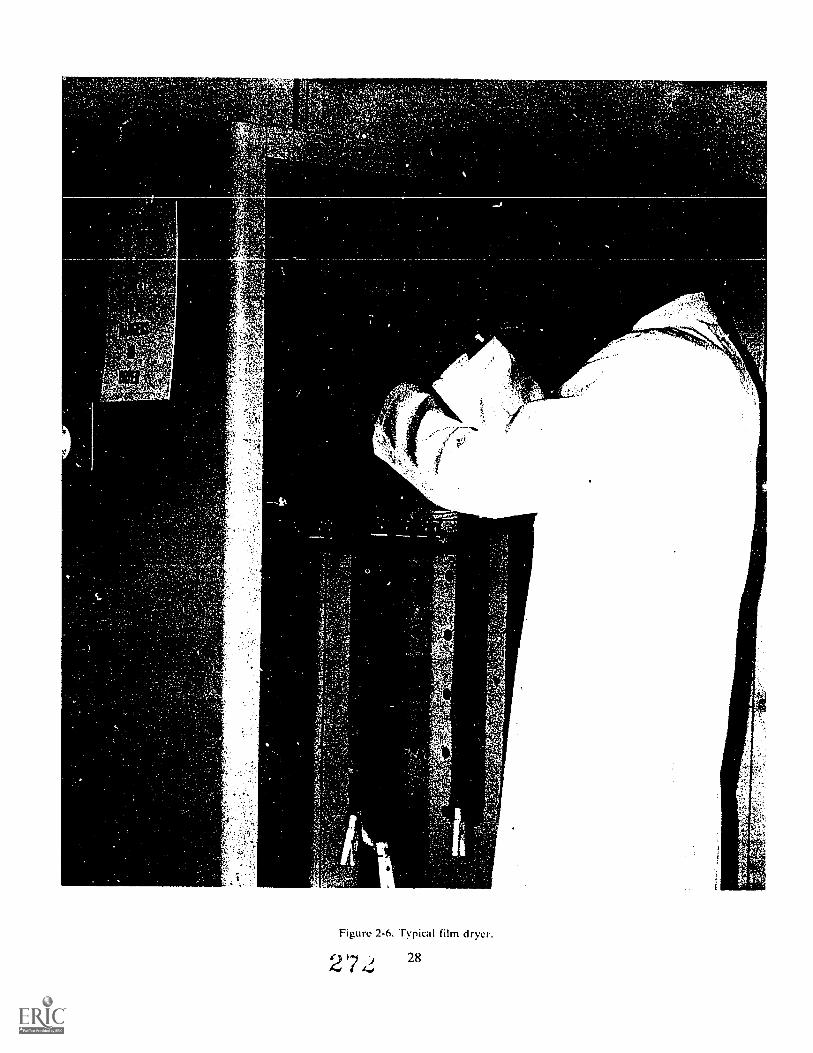
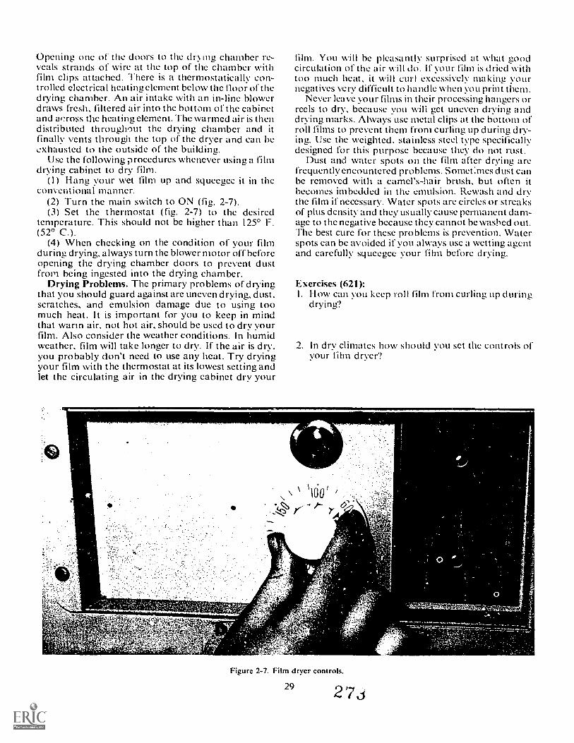
Opening one of the doors to the drying chamber re-veals strands of wire at the top of the chamber withfilm clips attached. There is a thermostatically con-trolled electrical heating element below the floor of thedrying chamber. An air intake with an in-line blowerdraws fresh, filtered air into the bottom of the cabinetand across the heating element. The warmed air is thendistributed throughout the drying chamber and itfinally vents through the top of the dryer and can beexhausted to the outside of the building.
Use the following procedures whenever using a filmdrying cabinet to dry film.
(1) Hang your wet film up and squeegee it in theconventional manlier.
(2) Turn the main switch to ON (fig. 2-7).(3) Set the thermostat (fig. 2-7) to the desired
temperature. This should not be higher than 125° F.(52° C.).
(4) When checking on the condition of your filmduring drying, always turn the blower motor off beforeopening the drying chamber doors to prevent dustfrom being ingested into the drying chamber.
Drying Problems. The primary problems of dryingthat you should guard against are uneven drying, dust.scratches, and emulsion damage due to using toomuch heat. It is important for you to keep in mindthat warm air, not hot air, should be used to dry yourfilm. Also consider the weather conditions. In humidweather, film will take longer to dry. If the air is dry.you probably don't need to use any heat. Try dryingyour film with the thermostat at its lowest setting andlet the circulating air in the drying cabinet dry your
film. You will be pleasantly surprised at what goodcirculation of the air will do. If your film is dried withtoo much heat, it will curl excessively ma kiniz V ournegatives very difficult to handle when you print them.
Never leave your films in their processing hangers orreels to dry, because you wili get uneven drying anddrying marks. Always use metal clips at the bottom ofroll films to prevent them from curling up during dry-ing. Use the weighted, stainless steel type specificallydesigned for this purpose because they do not rust.
Dust and water spots on the film after drying arefrequently encountered problems. Somet:mes dust canbe removed with a camel's-hair brush, but often itbecomes imbedded in the emukion. Rewash and drythe film if necessary. Water spots are circles or streaksof plus density and they usually cause permanent dam-age to the negative because they cannot be washed out.The best cure for these problems is prevention. Waterspots can be avoided if you always use a wetting agentand carefully squeegee your film before drying.
Exercises (621):I. How can you keep roll film from curling up during
drying?
2. In dry climates how should you set the controk ofiour Wrn dryer?
Figure 2-7. Film dryer controls.
29
-
273
3. What procedure would you use if you found duston your negatives after drying?
4. What three factors control the rate of film drying?
5. What problem does the excessive use of heat duringdrying cause?
6. Why are water spots a serious problem?
622. State the purpose and indicate basic techniques ofopaquing negatives.
Opaquing. The technique of opaquing is the act ofcovering undesirable pertions of a negative with alight-blocking dye called opaque. When this pro-cedure is used, the opaqued portions of the negativedo not produce any density and are therefore white in aprint. This technique is most often used to finish copynegatives to eliminate unwanted pinholes and lowdensity areas.
Opaquing Techniques. There are two basic types ofopaque that can be used. One type is number la reddye which is effective for blocking out backgrounds.The other is a water-soluble pigment, either red orblack, that is good for eliminating localized low den-sity areas such as pinholes and scratches. To opaquea negative you must have the proper working surfacewhere the light comes from beneath the negative. Acontact printer, X-ray lightbox, or plotting table areall equally effective for use as a working surface. Toprevent eye fatigue, you should block off any lightaround the negative.
When using la dye, saturate a cotton swab to abouthalf its length with the dye and apply it to the emul-sion side of the negative, outlining the parts of thenegative that you want to retain. Work slowly to allowenough time for the dye to absorb into the emulsion.With practice you will gain the experience to ac-curately outline the image. Sometimes it is necessaryto block both sides of the image if the area you want toblock is very thin in the negative. Very small areas canbe dyed using a mapping pen. It is also common prac-tice to outline the image with a mapping pen a-r1 thenfinish the job with a cotton swab or artist's h.
Opaquing with la dye is permanent and must there-fore be done very carefully. Errors can be removed ifdone quickly with a cotton swab and clean water. Ifyou cannot completely remove the dye with thismet: od try a 10-percent solution of sodium sulfite. All
30
the dye can be removed completely by soaking thenegative in the 10-percent solution followed by wash-ing and drying.
When using water soluble opaque. water can beadded to make it the desired consistency. It has thead ,'antage of covering in one application. Usc a smallartist's brush to apply it and then only to the base sideof the negative. This opaque is highly water solubleand can be washed off in water.
Exercises (622):1. What is the purpose of opaquing?
1. Complete the following statementsa. A pinhole that is opaqucd on the negative ap-
pears on a print.b. Opaquing with water soluble opaque is done on
the side of the negative.c. When you want to block a negative wit h a single
application used. A 10 percent solution of will
remove la red dye from a negative.
623. List the factors to look for when selecting nega-tives to be printed.
All of your work that went into exposing. proces-sing, and finishing your negatives come to a halt whenyou must E elect the negative to be printed. Your super-visor will probably do this more than you. However,you should know what the supervisor looks for.
Focus. Obviously your negative must be in focus.Contrary to certain popular beliefs, there is no focus-ing solution.
Exposure. Your negatives must be properly ex-posed. Given a choice of over and underexposed neiza-fives, choose the overexposed one. Underexposednegatives will not yield enough detail in the shadowsto produce a good print.
Defects. Scratches. pinholes, dust. curl: anythingthat will detract from the printed image should beavoided. Choose the negative with the least number ofdefects. (Assuming you have to choose one with anydefects at all).
Contrast. Choose the negative with the correctcontrast. The negative should 1-.ave a full range ofdensities. This should include the highlights, shadows.and middle tones.
Grain. If you processed your film properly you willnot have too much grain. Remember that as you en-large a negative the grain becomes more objectionable.
Identity. Those people or objects in the scene mustbe identifiable. Don't select a negative that will notproduce identifiable subjects.
Pleasing. The glal of printing is to produce a pleas-ing picture. A!! of your selection factors must be basedon whether the resulting print will be pleasing.
274
Exercises (623):I. I .ist five factors vou must consider when seleetiity
n,_gatives for printing.
2. What is the ultimate factor to consider when select-ing negi:'_ives for printing'?
624. State principles and facts about lettering nega-tives.
In Volume I we covered lettering of negatives quitebriefly. We go a little deeper in this section.
Remember that A FR 95-4. Audiovisual RecordsDispositiou Program is the regulation t hat governs thelettering of negatives. It gives the following informa-tion:
( I) Letter in the widest clear mai gin on the baseside. Information. starting from the left, must include.photograph number, calendar year. exposing unit,and classification.
(2) Numbers are assigned in sequence starting withnumber 1 on the first day of the calendar year.
(3) Exposures that are part of a sequential roll maybe identif led by adding, to the initial number for thefirst exposure, a letter suffix for each succeeding ex-posure in the sequence.
(4) For 35mm negatives in strips, assign the iden-tifying number to each strip of four to six exposures.Write the number on a clear margin of the first ex-posure or on an attached leader or titling strip.
Regardless of the size of the negative do not letteron an important part of the negative.
Lettering can be done by freehand or by mechan-ical lettering devices. The whole idea is to make surethat the writing can be read.
You can ase permanent or water based ink. The ad-vantage of each is the disadvantage of the other. Perm-anent ink cannot be washed off, either purposely oraccidentally. Water based ink can be washed off if youmake a mistake.
Your lettering procedures should be done on a lighttable. Just as in opaquing. you should block off thesurrounding light to reduce eye fatigue. You must alsowear cotton gloves to protect the negatives fromfingerprints.
After each lettering session, clean the pen(s) andwork area.
Exercises (624):I. Which regulation gives you lettering guidelines'?
31
2. On what part of a negat fte should you letter?
3. What would he tIt number of the third exposure ona sttip of 35mm negatives if the first exposure wasnumber 307?
4. What is the advantage of using water based ink toletter negatives?
5. Why should you wear cotton ploves while you arelettering?
625. Indicate principles and techniques applicable tothe handling and storage of negative material.
Handling and Storing Negative Niaterial. Can youafford to have your precious negatives lie around afteryour efforts in shooting. processing. and finishing?Proper handling and storage of your negatives is justas important as carefully loading ycar camera to beginthe photographic process.
Storage Problems. Moisture, strong light, and heatcan damage any film. Processed films should thereforebe stored on the main floors of buildings, never inbasements, which may be damp. nor in attics, whichmay be hot. A relative humidity of 25 to 50 percent anda temperature of 700 F.(21° C.) or less are best. It mustbe emphasized that high relative humidities are moredangerous than high temperatures because of the pos-sibility of fungus growth. In localities where insiderelative humidities of 60 percent or higher prevail, itmay be advisable to build a moisture-proof box inwhich to store a film collection with silica gel. The boxshould be provided with a rubber gasket to make atight-closing lid, and the films should be arranged topermit adequate circulation of air within the box.
To prevent physical damage. film should never betouched with the fingers except at the edges. Sheet androll-film originals should be kept in the transparentsleeves designed for storage purposes. If muchhandling is required. it might be wise to make dupli-cate negatives and keep the original master on file.
Exercises (625):I. What are three conditions that are likely to cause
damage to film?
2 7 D
2. 1:ihn should be stored at what relative humiditylevels.?
3. Iligh relative humidity can cause what kind ol filmproblem?
4. What should be done if there must be extensivehandling of a particular sheet of film?
2-4. Operator Maintenance
626. Complete a series of statements about operatormaintenance of film processing and finishing facilities.
Many of the tasks you perform in processing andfinishing fiim are tasks that maintain the service-ability of the equipment and facilities.
When you first start to work in a particular sectionof a lab, take a look around you and familiarize your-self with the total layout of your work environment.No two laboratories are exactly alike because thisdepends on their mission and the types of end productsrequired. However, certain things are common to allprocessing darkrooms. Every darkroom should have adry side and a wet side. The wet side is the processingsink and the chemistry involved. The dry side is a worksurface where unexposed film is loaded into filmholders and cassettes and exposed film is down loadedand prepared for processing.
A big part of operator maintenance is cleanliness.Leave the processing room in the condition that youfind it. That is. it should be clean and all equipmentthat you used should be returned to its proper storageplace.
A typical film processing room will have shelve.s orwall racks at the back or above the work surfacc forstorage of film hangers and reels. When selecting therequired number of reels or hangers that you will needto process a batch of film, inspect each of them fordamage that could give you difficulty in loading in thedark. A bent film reel is almost impossible to load anda film hanger with a missing retainer clip could causefilm to fall out during processing. Set bent or brokenitems aside and turn them into your supervisor ormaintenance personnel. A bent reel can sometimes bestraightened but usually needs replacement. An ad-vantage to storing reels and hangers out of the way isthat they are less susceptible to being damaged.
Another part of processing that is considered main-tenance, is the proper use of control charts and logs.
32
Many labs do not replenish their solutions because oflow usare.
Instead. they use a chart which adds developmenttime to the process for each succeeding batch of filmprocessed. The amount of time to he increased de-pends on the square footage of film previously proc-essed. You are responsible for adding up the totalsquare footage of film you are processing:m(1 addingit to the chart.
Also, don't forget to fill out your part of the w,,request on film processing.
Now let's go over to the wet side of the processingroom and talk about what mi:st be done.
Each deep tank has a floating lid which preventsoxidation of chemicals while they are not in use. Re-place these lids after processing. The process ther-mometer should he rinsed in water after checking solu-tion temperature and returned to a secure place. Rollfilm tanks. reels, and processing hangers must herinsed in running water after processing. Allow themto air dry naturally or a quicker method is to placethem in the bottom of the film dryer and let them dryalong with the film. Hand drying with cloth or papertowels should be avoided because they leave lint onthe equipment.
While you are waiting for your film and reels to dry.wipe down the sink backsplash and the outside of anyprocessitv tanks with a damp sponge rinsed out often.Wipe down the work surface also.
Most labs make it a weekly practice to thoroughlyvacuum the floors, work surfaces, and ledges that cangather dust. This is also the time for discarding usedchemistry and refilling the tanks with fresh solutions.Be sure that you thoroughly clean each tank of anyresidue before refilling them. Refill each tank so Canfilm hangers will be completely submerged when in-serted into them.
A word of caution on stainless steel. Never use anabrasive, such as scouring powder or steel wool toclean stainless steel because it will rust. Most marksare easily removed by using warm water and a sponge.For stubborn marks use a non-abrasive cleaning pad.
The film dryer is easy to maintain. Wipe down thedryer interior with a damp sponge once a week. Checkthe air intake filter ()hen and replace it when neces-sary. This filter is the same design as a furnace filter.It can be removed by lifting the loose panel whichserves as the floor to the dryer interior.
Exercises (626):I. What is the purpose of floating lids for processing
tanks?
2. How should processing reels be cleaned?
276

3. What should be used to clean stainless steel equip- 4. Where is the air lilter for film drying cabinet lo-ment? cated?
33

CHAPTER 3
Black-and-White Printing
THE FINAL OUTCOME of your work will be a print.So far we have covered exposure, composition, cameraassignments, and a multitude of photographic woes.Now it is time to make the final print. If you willpardon our boldness, let us say that the proof is inthe printing.
3-1. Preparing To Print
627. State the principles underlying specific darkroomprocedures and equipment for printing.
The location of the darkrooms depend on the avail-able space and the type and amount of work to beaccomplished. However, it is obvious that even a smallroom that is well arranged is an aid to production,whereas a rambling place that is too large is time-consuming. Furthermore, there is less waste, the workis less tiring, and personnel are less likely to haveaccidents when a standardized procedure is set up andclosely followed. Hence, the exposing, developing,rinsing, fixing, and washing of prints may proceedfrom left to right, or vice versa, but a definite routineshould be established.
Darkrooms should be provided with adequate freshair, and the stale and noxious air should be withdrawnby power blowers installed in the walls. It is also im-portant to maintain darkr rn temperature around70° F (21° C.). This temperature not only provides acomfortable environment to work in but also is a greataid in keeping the solution temperatures at the rightlevel.
The sinks should be centrally located to save un-necessary steps and time. They should be large enoughto hold the largest trays. Tray racks may be placedover the sinks so that any liquid that may splash orspill out runs into the sink and is disposed of throughthe drain.
Hot and cold running water is absolutely essential.There should be a number of convenient outlets. Inaddition, there should be a water mixing valve forcontrolling the temperature.
Darkroom Equipment. The carefully planned print-ing room should contain the following materials andequipment properly arranged so that the flow of work
moves easily from one stage to another: a contactprinter or projection printer (or both, etc.), an easel,safelights, a sink and trays for the solutions, graduatesfor measuring and mixing solutions, a thermometer,towels, at least two pairs of print tongs, an intervaltimer, and a wall clock with a sweep-second hand.(This list is not exhaustive. There should also be suit-able multiples of this equipment, depending on thenumber of workers in the lab.)
Trays. There should be five trays arranged in thesink so that prints can be processed in orderly progres-sion from developer, stop bath, first fixer, second fixer,and water tray. The water tray can hold the prints untilthey can be placed in the mechanical washer. Thetrays should be a minimum of 11 x 14 inches (28 x36 cm) for convenient use in processing 8 x 10 prints.
Timers. Most printing rooms contain two types oftimers: a large clock with a sweep-second hand andinterval timers connected to the contact and projectionprinters.
The clock timer most often has a black backgroundwith a luminous dial (Gra-Lab type, etc.). The dial hasa I-second graduation and a large sweep-second hand.It is normally located on a shelf over the developingtray. It should be used to time each step of the process.(Make sure that the clock is properly maintained.Through use and abuse, the clock can become inaccur-ate or cease to have a smooth sweep-second hand.)
There are a number of models of interval timersused to time the exposure when printing. Sonie arebuilt into the printer and others are connected elec-trically. However, all work on the same principle. Theexposure time is set by moving a pointer to the desiredtime on the dial: the exposure button is pressed andthe printing paper is expos,:d for the given time. Whenmaking a number of prints from one negative, thisprecise timing of exposure will insure greater uniform-ity of results. A FOCUS button is also provided onthe timer to permit the operator to have the printinglight on continuously to view the image for focusingand composition.
NOTE: Remember that good laboratory safety re-quires that ali electrical equipment be properlygrounded. Many a technician has received quite ashock by simultaneously touching a printer and inter-val timer when they were not properly grounded.
Print tongs. ;`,,ost technicians like to use print tongsto handle the print during processing. This technique
34
eliminates the need to handle the print with possiblehypo-stained hands that can Cause those unsightlywhite fingerprint marks and require the print to bedone over. If you use tongs, keep two points in mind:( I ) keep the tongs clean and (2) use two pair of tongsone pair to handle the print in the developer and carryit to the stop bath and the other pair to handle the printthrough the remaining steps (the use of two pair oftongs is necessary to prevent contamination).
Laboratory Cleanliness. In most photographic pub-lications, there is a section on defects. A close studyshows that many defects are caused by a lack ofcleanliness in the laboratory. It is much easier andcheaper to maintain a clean laboratory than to spendtime, effort, and materials to correct defects (i.e.,spotting prints or reprinting).
Remember to establish a wet side for the solutionsand a dry side for the printers. You must keep the dryside dry and free from contaminants. This carefulnessinsures much cleaner prints.
After processing operations, your hands are wetwith water or chemical solutions. In either case, rinsethem in clean water and dry them on a clean towelnot one contaminated with chemicals. Be sure thatyour hands are dry before your return to the dry side.
Avoid splashing chemicals. Splashing chemicals onthe floor or your clothing transfers them to the dryside, where they may ruin the prints. Chemicalssplashed on the floor may go unnoticed until they dryto a powder. Walking back and forth agitates thepowdery crystals and they become airborne. Ultimatelythese particles settle on your negatives and paper,causing spots that require retouching on negativesand spotting on the prints. Remember, therefore, toclean up all spills as soon as possible.
Regular cleaning of the laboratory is essential toquality production. No area should be overlooked.Floors should be mopped with a dust mop rather thana broom. Then use a wet mop to rinse the floor withclean water. Never use a dirty mop, as this only movesthe dirt from one place to another.
When a liquid is used to complete a cleaning job,remember that pin water will remove most chemicaldeposits. If a solvent is necessary, use as little as pos-sible while following all safety precautions connectedwith its use.
Cleaning as you go saves time and materials in thelong run. No one wants to work in a filthy environment,and you certainly cannot produce a high-qualityproduct under unclean conditions.
Exercises (627):1. Why is it important to have a definite routine to
your darkroom arrangement?
35
2. Why should the darkroom temperature be about70° F. (21° C.)?
1 What are the two types of timers you need whenprinting? What is each type used for?
4. Why do you need two sets ot print tongs?
5. Why is cleanliness so important'?
3-2. Preparing and Using Specified ProcessingSolutions
The proper selection, preparation, and use of yourdeveloper is very important to your print quality. Inthis section, we shall discuss these aspects of the printdeveloper. Then we shall cover similar aspects of stopbaths and fixing baths, as well as time/ temperaturecontrols.
628. Identify appropriate developers for print proces-sing and explain procedures used in the preparationof a print developer.
Selecting the Print Developer. There are a numberof print developers that are available. The developersvary in the tones and contrast they produce and thetype of paper for which they are designed. Normally,each manufacturer recommends a particular devel-oper(s) to match each type of paper. In selecting yourdeveloper, you must carefully consider the type ofpaper you are using and the result that you want.Following is a list of Kodak paper developers, theirrecommended dilution ratios, their processing times,and their purposes. This list is to just give you an ideathat several paper deveiopers exist. Other manufac-turers would produce a similar list. The basic paperdeveloper in the Air Force is the D-72 (used 1:2 for 2minutes), which is equivalent to Kodak's Dektol.
2 7 zi
Kodak Dincloper *Recommended Rangeand Dilution ot Dinelopment
Ratio Time II. Seconds
Dektol I:2) 45 to 180
Selectol I:1 I 90 to 240
Selectol Solt ( 90 to 240
Lktonal (I:1) 90 to 240
t
Yields neutral and coldtones on cold-tonepaper (e.g.. Koda-ii (imide).
Is suitable lor warm-tone paper and warmertones on other paper
Polylure).
Is a companion to Se-leoal hut gives lowercont rast.
Is specially designedtor %%arm-tone papersthat are to he toned(e.g.. Opal).
1 vS.o. I ,loci tkpcnd 11!1 liii ,1i11! IIed hut I he ienirdiaIIl I ciii OW
Preparing Print Developers. Once you have selectedthe developer you want to use, it should be properlyprepared for use. The following points should be con-sidered in making your stock solution. (Once you haveprepared your stock solution, you then can prepareyour working solution. The working solution is thestock solution diluted, if required, to its processingstrength.)
a. Safety. Throughout the preparation (and use) ofthe developer (or any other solution), rememberchemical safety. Chemical mixing should take place ina well-ventilated room. Always remember to add thechemicals to water. Do not swallow the chemicals orget them in your eyes. It is a good idea to wear rubbergloves and a face mask to eliminate chemical hazards.
b. Following directions. One of the most importantrequirements for mixing the developer is to follow themanufacturer's instructions. Failure to follow direc-tions results in solutions that do not perform consis-tently and properly. This wastes matecials.
c. Water supply. Impurities in the water can causestains. Use filters to remove impurities from the water.Where very critical work is being done, distilled watermay be required.
d. Mixing container. The mixing container and thestirring rod that are used must be clean and of the rightkind of material to prevent contamination or chemicalreactions. Stainless-steel, rubber, polyethylene, glass,and enameled steel are materials commonly used inchemical mixing equipment.
e. Temperature and sequence. To stress the pointagain, follow the manufacturer's directions regardingwater temperature (which may be higher for mixingthan for use) and the exact sequence that componentsare to be mixed.
Agitation. Proper agitation (stirring) duringmixing is most important to insure that the chemicalsare properly dissolved in the water. It is a good idea tointroduce only small quantities of the chemical at atime while stirring smoothly but vigorously. (Do not
stir so vigorously as to cause the introduction of airinto the solution or splashing of the solotioiL)
g. Storing. Proper storage is essential to preservethe solution. The developer can he stored in a stop-pered amber bottle or an opaque plastic container v, itha top or floating lid.
Exercises (628):1. Which of the following developers are used in print
processing?a. D-19.h. Dektol.c. Dd. DK.c. D -72.I. Metolflow.g. Selcctol.
2. Wnat should be your two main considerations whenyou are choosing a mixing container?
.3. What is probably the most important rule in thepreparation of a developer?
4. What type of protection should you wear whenmixing chemicals?
5. Too vigorous stirring when you are mixing the de-veloper can cause what problents?
629. Briefly explain steps to follow when you are de-veloping a print.
Using Print Developers. Once the stock solution hasbeen prepared, you c.,n make the working solution.The working solution prepared by mixing the stocksolution with the pr.oper amount of water. The workingsolution then can be poured into the developer tray forprocessing.
Once your darkroom is all set up, all solutions are atthe right temperature, and you have exposed your firstsheet, you should follow these steps to develop yourprint:
(1) Set your wall timer for the processing time. Theclock should start once the paper is in the tray. (Sometechnicians have the clock run all the time and then
36
2 6
start processing on any suitable whole minute. Thisprocedure saves resetting the clock or having to startand stop it all the time.)
(2) Place the print into the developer tray. You mayfind One of the following two ways to be easier for you.First, simply slide the paper into the tray. The othermethod is to lay the paper emulsion down into the de-veloper, then press it completely under the solution.The important thing is that you get the print wet quicklyand evenly. Air bubbles and developer splashes willcause circles on the print.
(3) Agitate the print constantly throughout the de-veloping time. This does not have to be violent, onlycontinuous movement is necessary.
(4) For an accurate 2-minute development (or othertimes as recommended), lift the paper after 1 minuteand 50 seconds of development (i.e., 10 seconds beforethe end of the development time). Drain the paper for10 seconds and then slide it into the stop bath. (Accurate timing of your processing is important in orderto determine proper exposure. Process by the clockand not by your eyes, as the density of the print underthe safelights and in the developer is deceptive.)
A slightly different procedure is used if you are de-veloping more than one sheet of paper at one time. Ifthis is the case, first, put one sheet at a time, emulsionside down, in the developer. Then proceed to agitateby puffing the first (bon, rn) sheet out from under andputting it face up on top of the stack of prints. Im-mediately follow it with the next sheet from the bottomand continue until the whole pile is face up. At once,pull them through again, one by one in the same order,to make a face down pile; continue to flip through theprints this way, carefully and regularly, until the endof the development time. Drain each print prior toputting it in the stop bath. NOTE: To insure consistenttiming, it is important to count as you go so that the,first print in is the first pint out.
Exercises (629):I. Print processing normally calls for what type of
agitation? Why?
2. How do you place a single sheet of paper into thedeveloper?
-c.x etr-3. What procedure should you follow to insure an ac-
curate processing time?
4. How should you agitate prints when you have toprocess more than one print at a time?
638. Indicate characteristics of stop baths and fixingbaths and explain how to prepare and me thesesolutions.
Once you have developed your print, you need torinse it in a stop bath and then make the image perma-nent through use of a fixing bath.
Purpose of the Stop Bath. A stop bath, though itdoes not make the image permanent, serves two im-portant purposes: (1) it stops or slows down develop-ment by neutralizing (a chemical reaction) or dilutingthe developer, and (2) it helps to prolong the strengthof the fixing bath.
Preparing and Using the Stop Bath. There are basi-cally two types of stop baths that are commonly used.These are water and acid. Plain water is used becauseit is readily available. However, it aets only as a i:ose.It dilutes the developer, but it does not neutralize it(i.e., no chemical reactions are taking place).
If you use only water, make sure that you have thewater continuously running into the tray to keep itfresh.
Most labs use an acid stop 'lath because the aeidreacts with the alkaline in the develo1;2r and neutralizesit. To make an acid stop bath, first make a 28-percentsolution of acetic acid from glacial acetic acid witheight parts water. To make the stop bath itself, add IVounces (44.4m1) of the 28-percent acetic acid to 32ounces (946.3m1) of water. (NOTE; Remember forsafety's sake, always add acid ( AAA rule) to the water.)
During use, the temperature of the stop bath shouldbe the same as the other solutions. After development,place the print in the stop bath and be sure to agitateit for 15 to 30 seconds (longer if more than one printis treated at one time). Stains may result if prints aremerely 1ft to stand in the solution.
For best results, read the instructions that come withthe paper that you are using. The instructions outlinethe type of stop bath to use and the time the printshould in the bath.
Purpose of the Fixing Bath. The fixing bath is im-portant because it chemically changes undeveiopedsilver (exposed or unexposed halides) into soluble saltsthat can be washed away. If undeveloped silver halideswere to remain in the paper. they would discolor whenexposed to light to which they were sensitive. Thisdiscoloration would result in fading of the image.
Preparing and Using the Fixing Bath. There are twotypes of solutions in common use: one with andt le other without hardener. I or average use, thepackagedityfko with hardener, mixed with water ac-cording to the manufacturer's directions, is advisable.The purpose of the hardener is to prevent excessiveswelling or softening of he emulsion. It is particularlyimportant when you are processing at high tempera-tures. If you want to give your prints a post-processingtreatment, such as toning, you should make your ownfixing bath without hardener. The Photo Lab Indexgives you formulas for these fixing baths.
37
2 8 (

In preparing to use a fixing bath, take a stock solu-tion of hypo as your working solution (no dilutionnecessary). Prepare a setup of two fresh fixing baths.(When the first bath is exhausted, usually after proces-sing two hundred 8 x 10 prints per gallon, replace itwith the secot.d fixing bath. A fresh bath then replacesthe second bath.) The exact amount of time in eachbath varies with the particular fixing bath, its tem-perature, and the paper being processed; but normallyit would be 3,-5 minutes per bath. 0:35EIMEBEEGINCitwzivis===w sin-coated projection paper CUM can befixed in 2 minutes.) The length of time in the bath isimportant because too much time can cause bleachingand too little won't do a permanent job. The tempera-ture of the bath should be similar to the other solu-tions. Proper agitation is ako very important; withoutit, uneven fixing may result.
A print can be examined under a white light after ithas been properly fixed for 2 minutes.
Exercises (630):Why is a stop bath an aid to accurate developmenttimes'?
2. What is the main advantage of an acid stop bathover a water stop bath?
3. How long should a print stay in a stop bath?
4. What is the purpose of a hardening fixing bath?
5. What is the advantage of using resin-coated paper?
631. Explain how to control the relationship betweendevelopment time and temperature in print processing.
Establishing Time/Temperature Controls. Just as infilm processing, the factors of solution temperatureand the length of time the sensitized material is in thesolution are important factors in determining thequality of the result. If the paper is developed for tooshort a time or at too low a temperature, a weak, low-density, low-contrast print will result. Underdevelop-ment can result in a loss of detail in the highlight por-tion of the subject. On the other hand, if the print isdeveloped for too long a period or at too high a tem-perature, the result will bc a print with too much den-sity with a slight increase in contrast. Extreme over-development can lead to fogging.
38
The ideal procedure to control your proce.;sing timek to establish temperature control of all your solutions.By having all the solutions at the recommended OW F.(20° C.), you can follow through with the recom-mended times. This control can be established byusing a thermometer to check the temperatures and awater mixing valve to get the water for mixing thesolutions to the right temperature.
If you cannot establish a temperature of 68° F.(20° C.) you must modify your processing times ac-cordingly. Check the instructions that come with yourpaper or developer for a time/ temperature chart thatgives the appropriate time for the temperature you areusing.
Exercises (631):I . What the relationship between time and lempera-
ture when you are processing a print?
2. How can you establish temperature control of yoursolutions'?
632. Explain principles and procedures related to theagitation of prints during processing.
Agitation is very important in every step of printprocessing. We have mentioned it on a continuingbasis throughout the chapter, but now we will exploreit further to emphasize its importance in correct proc-essing.
Purposes of Agitation. Agitation is important inevery step in processing, but its importance can becomprehended best by understanding what takes placeduring development. During development, the solutionreduces the exposed silver halide grains in the emul-sion to metallic silver. In the process, a number ofoxidation and chemical by-products are formed. Theseby-products will retard development if not replaced byfresh solution.
When you have stagnant development (no agita-tion), some portions of the solution are richer in by-products than others, due to the fact that at regionsof high exposure, more development takes place thanat low exposure regions. For this reason too, develop-ment is retarded to a much greater extent at regions ofhigh exposure than at those of low exposure. A lack ofagitation also produces development mottle (streaks).This defect occurs because the diffusion of fresh de-veloper and reaction byproducts from within the emul-slon take the path of convection currents. hi theunagitated solution, these currents take slow, random,irregular paths, producing uneven du- elopment.
2
This same effect can take place in the other solutions.Improper agitation in the fixing bath can lead to stains anduneven fixing that will result in fading as time goes on.
Air bells can also be eliminated by proper agitation. Airbells are tiny bubbles in the developing solution, whichcan cling tenaciously to the paper emulsion and causesmall circular or elliptical clear spots to occur. A spothaving soft edges or one of low density indicates that thebubble grew smaller as development progressed or brokebefote development was completed.
Methods of Tray Agitation. When processing a singleprint at a time, you can agitate each of the solutions bycontinuously rocking the tray. For the fixing bath, youshould have continuous agitation for the first 2 minutes;you should then agitate at least once every minute afterthat.
When working with more than one print, you move theprints rather than the tray, leafing each print in rotationfrom bottom to top throughout the processing. It isimportant to count each print as you go, so that you cantransfer the prints in order from one solution to another.
Exercises (632):
I. What is formed during processing, thereby makingnecessary a continuous replacement of freshdeveloper?
2. What is mottle? How is it caused?
3. What are air bells? How do they affect a print?
4. When processing a single prim, you agitate by movingthe ; when processing groups of prints atone time, you agitate by moving the
3-3. Printing Papers
When you get ready to make a print, you will have tomake some choices. Surface, texture, base, graded orvariable contrast, and sensitivity of various photographicpapers are all considerations for you to think about.
In our particular lab you may not have to make thesedecisions because someone has ordered only one or twotypes of paper. However, it will benefit your overallphoto knowledge if you know some of the basiccharacteristics of photo printing papers.
633. Specify the characteristics of printing papers.
Black-and-white printing papers are available in manydifferent varieties. We can classify them into a few basic
39
types and classes, depending oa their speed, contrast, andcolor of image. They are further broken down accordingto the type of base. That is, their weight, color, surface,and texture.
Your choice of printing paper speed should be based onthe way you intend to use it. Slow, contact printing papersare usually silver chloride emulsions. Enlarging papers,which must be faster, usually have an emulsion of silverbromide and silver chloride. Some papers, called slowchlorobromide are used for printing portraits.
The type of emulsion not only affects the speed, it alsoaffects the color of the image. Slow chloride emulsionsgive warm tones, sometimes they even go brown.Chlorobromide papers differ in tone according to thedominant halides. Some chlorobromide papers are warmtoned and some of the faster chlorobromide papersproduce colder, blacker tones. Generally speaking, wecan say that warm-toned papers are slower then thecool-toned papers.
Contrast in printing papers is also controlled by theemulsion coating. Some papers, called graded contrastpapers, are coated to produce a certain contrast or tonalrange. To use them to achieve proper contrast, you musthave a selection of each grade, usually 1 through 4.Graded paper number 2 is considered to be normal. Thehigher the grade of paper, the greater contrast it produces.Low contrast negatives would require grades 3 or 4, whilehigh contrast negatives would be printed on contrast grade1 paper.
Other contrast controlling papers are called variablecontrast papers. With these you control the contrast byusing colored filters between the paper and the lightsource. The manner in which the emulsion is madecontrols the contrast.
A portion of the silver halides in variable contrastprinting paper are sensitive to yellowish light and producelowered contrast when printing through the appropriatevariable contrast printing filter. Other silver halides in theemulsion are only blue sensitive and produce highercontrast through the appropriate printing filter. Normalcontrast is achieved by printing without a filter or usingthe preferred method of printing through the filter ia theset that produces normal contrast. For Kodak polycontrastfilters, use the number 2 filter. For a ten-filter set ofvariable contrast printing filters, use the number 5 filterfor normal contrast.
One more characteristic of printing papers is the basematerial. Some papers are made with fiber- based paper.Others are made with a base that is coated with resin. Theresin-coated (RC) papers do not soak up water andsolutions like the fiber papers.
The greatest advantage of using RC papers is in thetime and water savings during the washing cycles. Thedisadvantages of RC papers are their lack of permanenceand their inability to produce jet-black tones like thefiber-based papers.
A special-purpose, panchromatic printing paper isneeded when making black-and-white prints from colornegatives. Kodak Panalure is an example of this type ofpaper.
261
The reason you need special paper is becausc of thecolor negative. A o or .regative contains dye images thattransmit all of the colors to light. If you used i. ginslblack-and-white printing paper that is sensiti ie to blueand green, you would not get a satisfactory image of thcred objects in the scene. Additionally, some colornegatives have an overall orange cast that reduces tr ntrastand exposure on normal papers.
Using the panchromatic type papers with colornegatives will give you very pleasing results. You also getan additional advantage in local density control. With thepanchromatic papers, you can change the density of anarea by using filters during the exposure.
Exercise (633):
I . From the following statements select those that aretrue.a. Slow coiLtact printing papers are made with silver
bromide emulsions.b. Warm-toned papers are usually slower than
cool-toned papers.c. Graded contrast paper number 4 should be used to
print a flat negative..d. Variable contrast paper is made with blue and red
sensitive silver halides.e. Resin-coated papers do not need to be washed as
long as fiber base paper.f. Paper used to print color negatives is
monochromatic.
634. Explain how to control paper contrast andidentify the various grades of paper in terms of theircontrast ranges.
Contrast of Graded Papars. The term "contrast" isused in the same manner for prints as it is for film.Contrast is the difference between the highlights and theshadows. A low-contrast print is dominated by graytones, while a contrasty print is dominated by blacks andwhites. A normal print should have a variety of tonesranging from white through black.
Since a print is viewed by reflected light, the emulsionmust be thin so that only a minimum amount of theincident light falling upon it is absorbed. Hence, there ismuch less concentration of silver compounds in printingemulsions than in film emulsions. As a result, theemulsion of the photographic paper should be exposednormally and developed fully in order to obtain the bestprint possible.
Contrast, however, is not totally controlled bydevelopment. Instead, your choice of printing papers
supplied with a variety of inherent contrasts, Is thesignificant factor. It is not always possible to produce1:egatives that are exactly normal in contrast.Consequently, variations in printing materials are made tocompensate for those negatives that are not normal and toproduce the best possible print. These materials are madewith several different types of emulsions and each type isadaptable to a negative of a certain contrast. All of theseemulsions are designed to record approximately the fullrange of tones in the negative and yet maintain a pleasingtonal contrast.
Contrast Grades. Most papers are made in severalcontrast grades. This range of contrast is essential for thephotographi:r, who wants to produce the best possibleprint from any type of negativethat is, from soft (lowcontrast) to hard (high contrast). Each manufacturer ofprinting paper has classified the range of contrastsaccording to its standards. Therefore, the contrast of aparticular grade number and description may not agreewith that of another carrying the same identifier. (Paperfrom the same manufacturer may also vary from oneemulsion batch to another and performance may alsochange with age.) Papers that are currently availableconform, in a broad sense, to the following scale:
62 40
No. 0 Extra softNormal peints from very contrastynegatives; very flat prints from normal and softnegatives; designed for contact printing.
No. I SoftNormal prints from contrasty negatives; flatprints from norr.al and soft negatives.
No. 2 NormalNormal prints from normal negatives;soft prints from low-contrast negatives; contrastyprints fron. contrasty negatives.
No. 3 Moderately high contrastNormal prints fromslightly soft negatives; contrasty prints fromnormal negatives.
No. 4 High contrastNormal prints from low-contrastnegatives; contrasty prints from normal negatives.
No. 5 Very high contrastNormal prints from very softnegatives; very contrasty prints from normiilnegatives.
No 6 Extremely high contrastNormal prints fromextremely flat negatives; ultra-high-contrast printsfrom normal and contrasty negatives.
'Grades 9. 5. and 6 ue not normally available through rcgular military supply channels
Control of Contrast. The degree of contrast controlthat can be exercised during printing byexposure/development combinations is very small. (Anexception is monocontrast portrait papers that are verysensitive to differences in processing.) Consequently, it ismost important to use the correct grade of paper as thecontrast control. The wide range of contrasts available isdifficult to appreciate without studying actual comparisonprints. Hence, during your training, you should produce aseries of piilds from a normal negative, each one on adifferent gradt of paper. Your tests then can be extendedto negatives having a variety of
2
contrasts. These tests will show you the effect of in-creasing or decreasing original negative contrastduring printing by the selection of the appropriatepaper grade. By this experience, you will gain anunderstanding of what you can achieve when given aparticular negative to print.
Exercises (634):1. State the contrast produced by each of the following
paper grides: 1, 3, and 5.
2. What contrast guide gives you normal contrast froma normal print?
3. What is the best way to control contrast in prints?
635. Describe the color sensitivity of variable-contrastpaper in terms of specific colors and control method.
Instead of stocking a number of different contrastgrades, many Air Force photo labs today prefer to usevariable contrast papers. These papers have one emul-sion made up of halides having different inherentcontrasts that can be controlled. In this section, weshall discuss the characteristics of this type of paper.
Variable-Emulsion Sensitivity. A variable-contrastpaper emulsion consists of combinations of halidesthat are sensitive to either yellow-green light or blue-violet light. The yellow-green sensitive halides controllow contrast, while the blue-violet ones control highcontrast. The particular degree of contrast is obtainedby inserting an appropriate filter between the printinglight source and the paper. The filter controls the colorof light that reaches the printing paper, thereby con-trolling contrast.
By using only one type cf paper and a set of filters,you can produce finer gradations of contrast than ispossible with graded papers. Additionally, you cancontrol contrast of localized sections of the printedimage. This can be done by dodging (holding back thelight from) all but a particular part of the print whenthe appropirate filter is in place. Then proceed tododge the just printed portion when another filter iFbeing used. For example, the low-contrast portion cian image could be improved by printing with blue-violet light, while the harsh part could be softened byprinting with yellow-green light.
Exercises (635):1. Halides in variable-contrast paper are sensitive to
what colors of light?
2. What tool is used to control the color of light ex-posing the variable-contrast paper?
636. Indicate the appropriate printing filter to achievea desired print contrast, and specify Kodak and wrat-ten filter characteristics.
41
Variable-contrast emulsions are so designed thatwithin a single emulsion you have available varyingdegrees of inherent contrast. This inherent contrast iscontrolled by the color of light used to expose the printmaterial. The color of light is, in turn, controlled by theuse of filters.
Printing Filters. Each photographic paper manu-facturer produces different types of variable-contrastpapers and an appropriate set of filters. For example,Kodak manufactures five variable-contrast papersPolycontrast, Polycontrast rapid, Polycontrast rapidRC (resin-coated), Ektamatic SC, and Portralure(these papers vary in tone, speed, and surfaces, etc.)and seven filters. The seven filters are numbered from1 through 4 in increments of 1/ 2 and progressivelychange in color from a light yellow (1) to a dark rnag-enta (4). Yellow filters are used to produce low contrastbecause they absorb blue light and transmit grecn(and red). The magenta filters produce high contrastbecause they absorb green and transmit blue (and red).(The paper is not sensitive to red.) Using a number 2filter or not using any filter will produce no: mal con-trast. Filters are usually made out of plastic or acetateand can be used in contact or projection printing.
After you have selected a suitable variable-contrastpaper (for example, Polycontrast) for your printing,you must evaluate the contrast of your negative. Ahigh-contrast negative may require the use of a low-contrast filter, while a low-contrast negative may re-quire a high-contrast filter. If the negative is normal,you can use either a number 2 filter or no filter at all.For example, if your negative were slightly low-con-trast, you would choose a number 3 filter. (If you treatthe Kodak filter numbers as "paper grades," you willhave no trouble in choosing the appropriate filter.Other filter sets may require different selectionstandards.)
In terms of safelights, the Wratten OA filter (yellow-green), which is "safe" for graded-contrast paper,cannot be used with variable-contrast paper. Since thepaper is sensitive to green, using the OA safelightwould fog it. The safelight filters recommended forvariable-contrast papers are the DuPont S-55X(orange-brown) or the Wratten OC (amber).
Printing filters should be treated with the same careas filters used over a camera lens. A dirty, scratched,or faded printing filter will degrade the prin:zd image.
28o

Exercises (636):I. Which Kodak printing filter should you use to
achieve normal contrast when given each one of thefollowing types of negatives?a. Normal negative.
b. Very-low-contrast negative.
c. High-contrast negative.
2. What is the range of Kodak filters for variable-contrast papers?
3. Why should you avoid using a safelight with aWratten OA filter when producing prints onvariable-contrast paper?
637. Define the term "paper surface" and briefly ex-plain why surface selection is important in producingprints.
The final effect of a print depends to a great degreeupon the surface of the paper on which it is printed.For this reason, papers are manufactured with a widevariety of surfaces, thus permitting the selection of asurface that contributes the most to the purpose forwhich th- Int is intended. In this section we shallcover a fe )asie surface types you can choose from.The information can be applied to both variable-contrast and graded papers.
The wide variety of paper surfaces available makespossible the careful selection of a surface that con-tributes to the overall visual effect of a print. Thesurface characteristics of a paper are no less importantthan tint or tone in producing a print that accuratelyportrays the subject. (When we speak of tint, we arereferring to the range of colors of the print paper stock.(he tint may range from a white to a cream, etc. Imagetone refers to the developed image color, which mayrun from blue-black to brown, etc.) The term "surface"refers to the finish and texture of the paper.
The paper's surface influences the amount of lightthat is reflected from the print. Textures are generallyidentified as snwoth, fine-grained, or rough. There arealso specialized surfaces that resemble silk or suede.Many of these special surfaced papers can be orderedfrom the Federal Supply Catalog, Class 6750. (Papermanufactureis provide paper samplers so that you cansee the effect of their different types of papers.) Finish,or brilliance, refers to the shininess of the print, asdistinguished from its texture. For example, smooth-textured papers are made in both glossy and mattefinishes.
An extremely smooth surf:Ice, with regard to bothfinish and texture, looks bright because it reflects mostof the light falling on it. The maximum detail is there-fore revealed. A dull textured surface, as is found with
42
matte and sonic semimatte papers, scatters the lightand obscures detail. This scattering not only dims thehighlights but also makes the black or dark portions ofa print look grayish. However, such an effect is lessharsh and may add a mood to a picture in which detailis not critical as in scenics or portraiture.
Exercises (637):1. What is a paper's "surface"?
2. Why is it important to match the paper's surfacewith the image?
638. Distinguish between different types of papersurfaces.
You will develop taste and judgment in the selectionof the appropriate paper through experience. Youshould start by studying paper samplers put out by theleading manufacturers. After you have an idea of whatis available, follow up by printing a suitable negativeon a couple of different surfaces to see the effect thateach surface has on the resulting print.
The more common finishes are glossy, high luster,luster, semimatte, and matte. We shall limit our dis-cussion here to glossy, semimatte, and matte.
Glossy. The sheen of a particular surface is depen-dent upon how it reflects the light striking it. Practi-cally all of the light is reflected from a glossy surface.This great amount of reflected light gives maximumdetail and brilliance, which are required in many AirForce photographs. A very high gloss, needed for pic-tures to be reproduced in a base newspaper or otherpublications (such as this CDC), can be obtained byplacing a wet glossy print face down onto a chromesheet and allowing it to dry. However, to achieve themaximum gloss that the paper surface will produce,you must follow the manufacturer's directions. Forexample, certain papers must be ferrotyped (dried withthe emulsion in contact with highly polished surface),while the new resin-coated papers will air dry to ahigh gloss.
Semimatte. Semimatte papers have a smooth sur-face with little texturing. This type of paper dries toa semigloss or flat finish. Semimatte papers are suit-able for portrait work and other subjects where n. ixi-mum detail and contrast are not required.
Matte. The reflected light from matte surfaces isalmost completely diffused. These softer, less glaringsurfaces are preferred by most photographers forpictorials, portraits, landscapes, and other vir,ws notrequiring a great deal of detail and brilliance. Thesmooth paper bases have no pattern. The rougherbases have a noticeable texture that may vary from aslightly pebbled effect to a fabric-like texture resemb-ling linen or a very rough tweed. Smooth papers are
2 8 6
recommended for small prints that require good defini-tion and detail rendition. The rougher surfaces subduefine detail in proportion to the degree of roughnessand are useful for prints that do not depend upon detailfor interest.
Exercises (638):Match each description in column A with the appro-priate paper surface listed in column B.
Column .4 Column BHas greatest variety of surfaces. a. (flossy.(lives maximum brilliance. b. Semimatte.
3 Ills semigloss or flat finish. c. Matte.4 Is used for pictures to be reproduced
in publications.S Is suitable for a nonglarinu landscape
in which detail is to be subdued.6 Has a smooth surface with little tex-
turing and is suitable for portrait work.7 Gives maximum detail.
639. Define "tone" and "contrast" and specifyfactors used to determine and control them.
Deciding on the appropriate tone and contrast of aprint requires experience and judgment, since there isa variety of techniques and materials that are avail-able. In this section we shall discuss a few points tohelp guide you in this area.
Tone. The tone of the print primarily depends on thepaper/developer combination that is chosen. Manypapers are cold toned and tones tend toward blue-blacks. Other papers are warm, and render browntones. To achieve the appropriate tone, it is importantto follow the paper manufacturer's recommendationsfor developer type and processing procedures. Anotherfactor is correct exposure. Insufficient exposurerenders the tones too light; too much exposure rendersthem too dark. (NOTE: As a print finishing technique,chemical toning can be done after the print has beenprocessed in order to produce overall tints of many dif-ferent colors.)
Contrast. Contrast is the difference between thehighlights and the shadows. Your final print contrastdepends primarily on the inherent contrast of the nega-tive, the grade of paper or the filter and variable-contrast paper you have chosen, and the developer.Combining short exposure with longer development toproduce high contrast or long exposure and shortdevelopment to produce flatter prints is possible to alimited degree but is not generally recommended.
Tips on Controlling Tone and Contrast. Considerthe following points when deciding how the tone andcontrast of your prints should be.
a. Try to duplicate the tone and contrast of theoriginal subject. If the values of the print reproducethose of the original subject, your print is likely to havethe proper contrast. How much printing manipulation
is necessary depends to a great degree on the negative.If the negative does not reproduce the contrast theoriginal scene, it takes careful selection of paper,developer, exposure and contrast control techniques(grade of paper, dodging, burning-in, etc.) to obtainthe necessary results.
b. Preserve detail in both the shadows and high-lights. This preservation of detail is particularly impor-tant in Air Force photography because the final productis ()Ben needed primarily to provide a detailed render-ing of the subject. If the negative is very contrasty, itmay take a low-contrast paper, along with some burn-ing-in, in order to get the detail. Of course, if there isno detail in the negative to begin with, iherc is no wayto put it in the print.
c. The picture must fulfill the mission requirements.The use of the final product is the key to deciding whatto do. Is the print for the base newspaper where re-production requirements may call for a less contrastingprint? Is it for display on a wall where the impact onthe people passing by is very important? ( In sueh acase, you must consider the lighting in the room, thecolor of the walls, other pictures or decor, etc.) Is itbeing used in an accident investigation where maxi-mum detail is vital? The variety of uses for the result-ing print necessitates your learning a number of tech-niques and being knowledgeable about an the materialsin your lab's supply. Know what you can do with whotyou have.
43
Exercises (639):1. Define print tone.
2. Define print contrast.
3. Describe how the print is controlled by the choice ofmaterials and techniques that are used.
4. List three important factors in controlling printcontrast.
5. Why must you consider mission requirements asyou carry out your printing work?
640. Given a series of printing situations, choose theappropriate printing filter to achieve the required con-trast and state proper procedures related to the use ofvariable-contrast filters.
2 8
Using Variable-Contrast Printing Filters. To meettheir printing requirements, the majority of base photolaboratories are standardizing on variable-contrastpaper rather than graded paper. To control contrastwith this type of paper, you must use variable-contrastfilters.
As we mentioned when %VC' wcrc discussing printmaterials, variable-contrast papers have orthochro-matic sensitivity. The blue-sensitive part of the emul-sion controls high contrast, and the green-sensitivepart controls low contrast. By interposing the appro-priate variable-contrast filter between the light sourceand the paper, the contrast can be controlled. Deperd-ing on the paper's manufacturer, there are sets offilters running from yellow (for low contrast) throughdark magenta (for high contrast).
When making your test strips to determine correctexposure, you need to also determine the contrast. Youdo this by examining the shadow area of a test stripthat has the correct highlight exposure. If the shadowarea of this test is too light, the paper does not havesufficient contrast. If the paper has insufficient con-trast, a higher-numbered fiRer is needed. Ifthe shadowarea is too dark, the paper has too much inherent con-trast and a lower-numbered filter is needed.
Earlier we presented a basic guide in determiningthe proper graded paper to use to achieve a desiredamount of contrast. Now let us examine a similar basicguide in determining the correct filter to use. (Theguide below is based on using a 1, 2, 3, or 4 Poly-contrast (Kodak) filter. The principles would apply to,...11er makes of filters and to the application of inter-rr ediate values such as 11/2, 21/2, or 31/2, etc.)
Filter ResultsNo. I Soft--Normal prints from contrasty negatives; flat
prints from normal and soft negatives.No. 2 NormalNormal prints from normal negatives; soft
prints from low-contrast negatives; contrasty printsfrom contrasty ne.gatives.
No. 3 Moderately high cmitrast--Normal prints fromslightly soft negatives; contrasty prints from normalnegatives.
No. 4 High contrastNormal prints from low-contra'tnegatives; contrasty prints from normal negatives.
Figures 3-1A and 3-1B show a series of prints pro-duced by using the above filters.
When using variable-contrast filters, you shouldremember the following:
a. The filters are available in acetate rolls for con-tact printing or as individual filters for projectionprinting.
b. When in use, the filters should be clean and ingood order (not scratched). Like all filters, eventuallythe printing filters will fade and have to be replaced.
c. When being used, the filter should lie flat toinsure even exposure over the entire print.
d. The densities of the filters are indicated by thedifferent numbers. For example, a No. 4 filter is darkerthan a number 3. This being the case, when printing
44
with a No. 4, your exposure times need to he relativelylonger. It is a good idea, therefore, to make additionaltest strips when you change filters.
e. Some contact printers commonly used by the AirForce are equipped with argon exposing lamps. Sincethese lamps are very rich in blue and ultraviolet (andvery limited in the green and red spectrum), they can-not be used for printing variable-contrast paper. It ispossible to modify such a printer by installing whiteincandescent lamps.
f As we have previously discussed, dodging andburning-in can be effective in controlling local density.It is also possible to change filters to control localcontrast. For example, it might be better to give theprint an overall exposure with a number 2 filter andthen burn in the sky with the aid of a number 3 filter.It is a good idea to work from a full test print to deter-mine the best approach.
g. Study the manufacturer's directions that comewith the paper so that you can use their filter/ papercombination to best effect. (As we inaicated early inthis volume, too many of us are guilty of throwingaway the manufacturer's directions that come with ourphoto materials. By keeping them in a reference book,we could have a tremendous source of infor-nation thatwould save our time and materials.)
Exercises (640):I. Determine the correct Polycontrast filter (1, 2, 3, or
4) to be used in the following printing situations.a. You have been given a soft negative that must
be printed to a high contrast.b. A contrasty negative must be printed to normal
contrast.c. A normal negative must be printed to very high
contrast.d. A low-contrast negative must be printed to
normal contrast.e. A low-contrast negative must be printed to low
contrast.
2. What type of variable-contrast filters are used in434)444÷trtt printing?
3. How should filters be maintained for printing?
4. What can't you use argon lighting in variable-contrast printing?
2 b

,
oe.14
POLYCONTRAST Fl LTER 1
.-0
.1-
41110. ,
POLYCONTRAST F I LTE R 2
Figure 3-IA. l'se of variable contrast printing filters.
45 2
231-276C
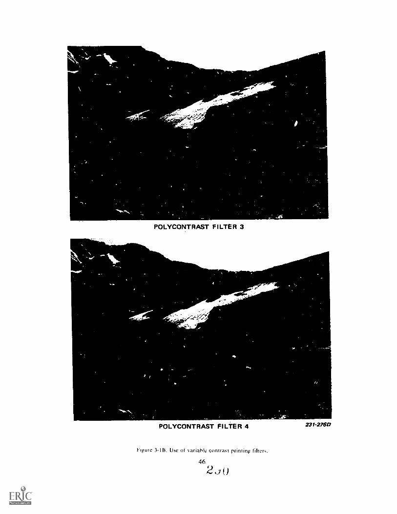
-0J-
4111110."-
POLYCONTRAST FILTER 3
POLYCONTRAST FILTER 4
Figure 3-113. Use of variable contrast priming filters.
46
2
231-27613
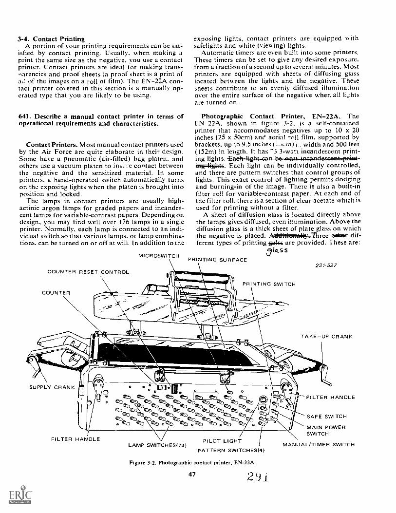
3-4. Contact PrintingA portion of your printing requirements can be sat-
isfied by contact printing. Usually, when making aprint the same size as the negative, you use a contactprinter. Contact printers are ideal for making trans-narencies and proof sheets (a proof sheet is a print of
of the images on a roll of film). The EN-22A con-tact printer covered in this section is a manually op-erated type that you are likely to be using.
641. Describe a manual contact printer in terms ofoperational requirements and characteristics.
Contact Printers. Most manual contact printers usedby the Air Force are quite elaborate in their design.Some have a pneumatic (air-filled) bag platen, andothers use a vacuum platen to insu7e contact betweenthe negative and the sensitized material. In someprinters, a hand-operated switch automatically turnson the exposing lights when the platen is brought intoposition and locked.
The lamps in contact printers are usually high-actinic argon lamps for graded papers and incandes-cent lamps for variable-contrast papers. Depending ondesign, you may find well over 176 lamps in a singleprinter. Normally, each lamp is connected to an indi-vidual switch so that various lamps. or lamp combina-tions. can be turned on or off at will. In addition to the
COUNTER RESET CONTROL
COUNTER
MICROSWITCH
exposing lights, contact printers are equipped withsafelights and white (viewing) lights.
Automatic timers are even built into some printers.These timers can be set to give any desired exposure.from a fraction of a second up to several minutes. Mostprinters are equipped with sheets of diffusing glasslocated between the lights and the negative. Thesesheets contribute to an evenly diffused illuminationover the entire surface of the negative when all lhtsare turned on.
Photographic Contact Printer, EN-22A. TheEN-22A, shown in figure 3-2, is a self-containedprinter that accommodates negatives up to 10 x 20inches (25 x 50cm) ane aerial rnll film, supported bybrackets, up ...o 9.5 inches (-.A.:in) i width and 500 feet(I52m) in length. It has -3 3-watt incandescent print-ing lights. -Eaeh-4144-Gan-he-4vaLt-alca-FidesGea,tptizitr-irrig=liiigki.ts. Each light can be individually controlled,and there are pattern switches that control groups oflights. This exact control of lighting permits dodgingand burning-in of the image. There is also a built-infilter roll for variable-contrast paper. At each end ofthe filter roll, there is a section of clear acetate which isused for printing without a filter.
A sheet of diffusion Plass is located directly abovethe lamps gives diffused, even illumination. Above thediffusion glass is a thick sheet of plate glass on whichthe negative is placed. A410;i4;i4sim4.1hree age( dif-ferent types of printing fje1444 are provided. These are:
014.55PRINTING SURFACE
PRINTING SWITCH
231-527
TAKEUP CRANK
SUPPLY CRANK
FILTER HANDLE
EE111
cz) ez) ez) ez)ezD en en en 1,,fte_ ez)
(c:p\cb (t) 6) ez) ez)
4Z) (D, ez) ezp ez) ez)
LAMP SWITCHES(73)PILOT LIGHT
PATTERN SWITCHES(14)
Figure 3-2. Photographic contact printer, EN-22A.
47 291
FILTER HANDLE
SAFE SWITCH
MAIN POWERSWITCH
MANUAL/TIMER SWITCH
a. One dear printing glass. (You can use your ownindividually cut masks taped to the glass.)
b. One masked for 9 x 9-inch (22 x 22cm) negatives.c. One masked for 9 x 18-inch (22 x 44cm) nega-
tives.
Exercises (641):Complete the following statements on the descriptionof contact printers:1. The negative and the paper are held down by the
2. ['rec .. available in most contactprinters .irol of
3. The EN 22A can handle roll film negatives up toinches in width.
4. A roll is used for printing variable-contrast paper.
5. A sheet of glass is used to provideeven illumination.
642. Specify techniques and procedures related tocontact printing.
When ciL1Ined indc i slorrl lighting, a negative hasa shiny side and a dull side. The shiny side is the filmbase: the dull side is the emulsion layer side. A similarexamination of photographic paper shows that thepaper has a slight curl toward the emulsion and, par-ticularly with glossy paper, the emulsion side reflectsmore light.
To produce contact prints, the dull side of the nega-tive must be in contact with the shiny side of thepaper: that is, they must be emulsion to emulsion. Ifthe negative base is in contact with the paper emul-sion, the photograph will be reversed from side to side.In some cases, such a reversal in the print is not readilyevident, but it becomes strikingly so if there are lettersor numbers in the picture area.
The exposing light must pass through the negativefirst; therefore, in a contact printer, the exposinglights are directed upward. The negative is placed onthe glass with the emulsion side up, and the paper islaid emulsion side down on top of the negative. Then
48
the lid of the printer box is lowered to press the nega-tive and paper together. (NOTE: To prevent slippage.it may be necessary to tape the negative to the dass.This technique is particularly useful when a largenumber of prints have to be produced. Later in thechapter, we refer to this glass when we discuss the useof masks.)
Earlier we mentioned that contact printing is usedto make proof sheets. A proof sheet is made by print-ing strips of roll film negatives (35mm. 120. etc.) orindividual sheets of cut film on one 8 x 10 sheet. Asingle exposure is given for all of the negatives. Be-cause this is often a compromise exposure, some nega-tives will produce poor images. These negatives areseparately grouped according to contrast and density:then they are reprinted. Proof sheets are excellent forrecord keeping and ,clect: , I yes to meet mis-sion requirements.
REMEMBER: the p, contact printing is toproduce only image-size prints that reproduce theoriginal scene from the negative as accurately aspossible.
Exercises (642):I. How should the negative and the print paper be
placed on the contact printer for printing?
2. How can you determine which side of photographicpaper is the emulsion side?
3. In contact printing, how should the size of theimage in the negative compare with the size of theimage in the print?
4. How should you make a proof sl-
3-5. Projection PrintingProjection printing differs from contact printing in
that the negative is separated from the sensitizedpaper. The negative image is projected by means ofincandescent light and an optical system onto thesensitized paper. By altering the negative-to-lens dis-tance and the lens-to-paper distance, it is possible toreduce, maintain, or enlarge the image size. Becausemost projection prints are made at an enlarged scale.it has become common to refer to projection prints asenlargments and to call a projection printer an en-larger. The preferred terminology is "projectionprinter," since the capability of reduction is present.
9
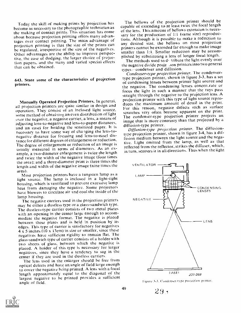
Today the skill of making prints by projection hasbecome as necessary to the photographic technician asthe making of contact prints. This situation has comeabout because projection printing offers many advan-tages over contact printing. The main advantage ofprojection printing is that the size of the prints canbe regulated, irrespective of the size of the negatives.Other advantages are the ability to improve perspec-tive, the ease of dodging. the larger choice of projec-tion papers, and the many and varied special effectsthat can be obtained.
643. State some of the characteristics of projectionprinters.
Manually Operated Projection Printers. In general,all projection printers are quite similar in design andoperation. They consist of an inclosed light source.some method of obtaining an even distribution of lightover the negative, a negative carrier, a lens, a means ofadjusting lens-to-negative and lens-to-paper distances,and an easel for holding the sensitized paper. It isnecessary to have some way of chalging the lens-to-negative distance for focusing and lens-to-easel dis-tance for different degrees of enlargement or reduction.The degree of enlargement or reduction of an image isusually measured in terms of diameters. As an ex-ample, a two-diameter enlargement is twice the lengthand twice the width of the negative image (four timesthe area): and a three-diameter print is three times thelength and width of the negative image (nine times thearea).
Most projection printers have a tungsten lamp as alight source. The lamp is inclosed in a light-tighthousing, which is ventilated to prevent excessive lampheat from damaging the negative. Some projectorshave biowers to circulate air and cool the inside of thelamp housing.
The negative carriers used in the projection printersmay be either a dustless type or a glass-sandwich type.The dustless-type carrier consists of two metal plateswith an opening in the center large enough to accom-modate the negative format. The negative is placedbetween these plates and is held in position by itsedges. This type of carrier is satisfactory for negatives4 x 5 inches (10 x I3cm) in size or smaller, since thesenegatives have sufficient rigidity to remain flat. Theglass-sandwich type of carrier consists of a holder withtwo sheets of glass, between which the negative isplaced. A holder of this type is necessary for largernegatives, since they have a tendency to sag in thecenter if they are used in the dustless carriers.
The lens used in the enlarger should be free fromoptical defects and have an angle of field large enoughto cover the negative being printed. A lens with a focallength approximately equal to the diagonal of thelargest negative to be printed provides a sufficientangle of field.
The bellows of the projection printer should becapable of extending to at least twicc the focal lengthof the lens. This amount of bellows extension is neces-sary for the production of 1:1 (same size) reproduc-tions. Although it is possible to make a reduction toany desired size, the bellows on most projectionprinters cannot be extended far enough to make imagesmaller than 1:1. Smaller reduction may be accom-plished by substituting a lens of longer focal length.
The methods used to & tribute the light evenly overthe negative divide proje . _ion printers into two generaltypescondenser and diffusion.
Condenser-type projection printer. The condenser-type projection printer, shown in figure 3-3, has a setof condensing lenses between printer light source andthe negative. The condensing lenses concen.rate orfocus the light in such a manner that the rays passstraight through the negative to the projection lens. Aprojection printer with this type of light source repro-duces the maximum amount of detail in the print.For this reason, negative defects such as surfacescratches very often become apparent on the print.The condenser-type projection printer projects animage that is more contrasty than that projected by adiffusion-type printer.
Diffusion-ope projection printer. The diffusion-type projection printer, shown in figure 3-4, has a dif-fusion medium between the light source and the nega-tive. Light emitted from the lamp, as well as thatreflected from the reflector, strikes the diffuser, which,in turn, scatters it in all directions. Thus when the light
49
CON DE NSINLENSES
EASEL231-268
L ENS
Figure 3-3, Condem.er-type prujection printer.

----b.LAMP
NEGATIVE
/
4110.
LAMPHOUSING
DI F F USI NGGLASS
LENS FOCUSING
EASEL
ADJUSTMENT
231-269
Figure 3-4. Diffusion-type projection printer.
reaches the negative, it is traveling in no specificdirection but in many directions.
The effect of using diffused illumination is thatminor negative defects are not clearly recorded in theprint. There is a general softening of the image sharp-ness, which is accompanied by a reduction in imagecontrast. Diffusion-type printing is favored in por-traiture and scenic-type work. However, the over-whelming majority of your Air Force printing is doneon condenser-type enlargers.
Exercises (643):Complete the following statements regarding projec-tion printers:I. Fine focusing is primarily controlled by the
distance.
2. The degree of enlargement is in terms of
3. Negative carriers are either ortypes.
4. The enlarging lens normally has a focal lengthequal to the of the negative.
5. A lens with a focal length longer than the diagonalof the negative being printed will project aimage.
6. A -type enlarger will project the morecontrasty image.
7. A -type enlarger is good for printingnegatives that have defects.
644. Specify operational characteristics and proce-dures of the EN-52B projection printer.
Characteristics of the EN-52B Projection Printer.The EN-52B projection printer shown in figure 3-5,is the type of projection printer you will find in your
Figure 3-5. Projection printer. type EN-52B.
base photo lab. It is a table-site unit used to make en- 2. You earl print up to a negative on thelargements of photographic negatives running from EN 52B.35mm through 4 x 5 inches (10 x I 3cm). Three lensesare available: f 3.5. 50mm (ideal for 35mm): f 4.5.100mm (120 or 70mm film) and f 4,5. I50mm x 5).The printer consists of 8 major assemblies These 3. The negative is inserted side down tounits are the baseboard, easel, filter wheel, lens. nega- make the print.tive carrier, condenser. lamphouse. and girder as-semblies.
Operating The EN-52B Projection Printer. Use thefollowing checklist when operating the EN .-52B Pro- 4. The tensioning knob must be loosenedjection printer: before you can raise or lower the
(I) Make sure that the condenser, which is locatedimmediately below the lamphousing. is securely lockedin place.
(2) Sleet the proper negative carrier for the nega- 5. To obtain maximum enlargement. it is necessary) that you want to print and position a 1,.1:ative to the oc14iatititter-, -p j.e c+0
in the negative carrier so that the emulsion is facingdown and the negative is upside down. Placing the Aeta q 5-e ;14negative upside down will make it project uprightcnto the printing easel.
(3) Raise the lamphouse condenser assembly, insertthe negative carier. and lower the assembly. 645. Explain the problems encountered techniques
(4) Turn th,: overhead lights off. set the timer to used in projection printing.the FOCUS position. place a sheet of white paper inthe easel (a sheet of printing paper placed upsidedown can be used) and focus the image with the lens The prerequisites for good projection prints are (I)wide open and no filter installed undet ,he lens. good negatives. (2) a clean enlarger. (3) the proper
(5) After initial focusing. raise or lower the projec- contrast g,.ade of printing, paper or variable-contrasttion assembly to achieve desired image size and crop paper and filter set, (4) correct exposure, and (5)ping and refocus the image. Raising the assembly careful processing and finishing. As you can see, youenlarges the image. and lowering it reduces image size, must control a number of factors in order to achieve
NOTE: The EN-52B has the autofocus feature but top-quality results.it is set up to be used with a specific easel. Using an Negative Selection. Although most any negative caneasel other than the one that comes with the projector be printed by projection, there are a few characteristicschanges the distance relationship that allows the auto- that are particularly desirable. A good negative hasfocusing feature to work. Therefore, it is always good normal density and contrast. It is sharp and free frompractice to refocus the image each time you raise or such defects as scratches, abrasions, dust, and finger-lower the projector assembly on its track. prints.
(6) Once you have proper image size and cropping. Your negatives should be handled carefully in ordertighten the tensioning knob on the to prevent fingerprints and smudges that will degradelock the projector head in posit.° . CALI-WON: your image. Lint and dust particles hold back the light
lways relexe the tensioning knob during printing, and their shadows produce whiteecti3M1Osembly,.444-iuszack. If you don't release the spots on the prints that are very unattractive additionsA
tensioner, you may seriously damage the projector. to any photograph. Therefore, both the negative and(7) To make a test print, set the timer to the TIME the negative carrier should be cleaned with a tuft of
and select an exposure time. Stop down your cotton moktrued in alcohol or film cleaner. If theJesired f/stop, remove the focusing sheet negati\ properly processed and handled, how-
shret of print'ng paper into the c ever, ri usua",.. he cleaned with a sof. brush,: button. light vill come on ,i)des i air oiasts from an aerool can.
Lor the time that you set and shuts off auto- Printer and Easel Adjustments. Place the negativematically to end the exposure. in the carrier so that the emulsion side is down and
facing the emulsion of the paper. Replace the negativecarrier in the projection printer and make sure that
Exercises (644): it is properly seated.Complete the following statements related to the de- Adjust the paper corner guide and the maskingscription and operation of the EN; 52B: device on the easel to form the borchr width and print1. When printing 120 film, you will normally use the size needed. As an aid for composition and accurate
mm lens, focusing of the image, place a sheet of white paper inthe printing position on the easel. The base side of afinished print serves nicely for this focusing aid. Then
51
293
turn on the appropriate safelights and turn off thewhite lights. Turn on the printer light and open thelens to its maximum aperture.
Focusing and arranging the composition of theprojected image should be accomplished with the lenswide open. The brighter image is easier to see foraccurate focusing. When you are ready to print, youshould stop the lens down two or three stops for sev-eral reasons. First, almost all lenses project a sharperimage when stopped down a couple of stops. Second.stopping down the lens causes a greater depth of focus,which provides a margin of safety for any slight errorin focusing. Finally, moderate printing times (e.g., 10seconds) permit dodging and burning in.
Now studv the image carefully. (The picture isto compose if the scene if right side up. If it is
upside down, either rotate the carrier or remove thecarrier and reposition the negative.) Most printingpapers are rectangular: therefore, you should decidewhether to use a vertical or horizontal format. In manycases, the manner in which the scene is composed(horizontally or vertically) on the negative is the con-trolling factor. Furthermore, most photographs can beimproved by cropping.
To bring the image to the desired size, raise or lowerthe printer head until the approximate size is reached.Then bring the image into sharp focus by changing thelens-to-film distance. However, because the size of theimage will be changed slightly by focusing, the printerhead should be readjusted. This readjustment involvesmoving the enlarger head and then refocusing. Thisoperation should be repeated until the desired size isreached and the image is in sharp focus.
After the image is correctly composed and focused,the aperture of the lens should be closed down. Thenturn off the printing light, remove the white focusingpaper, and place the printing paper (emulsion side up)on the easel. You arc now ready to expose and processyour test strips.
Exercises (645):I. What problem will dust and lint cause or your
print? How can the problem he reduced'?
,(.,a the emulsion of the negative and thepal -ranged'?
3. For a given negative size. how is image sizt- con-trolled in projection printing'?
4. In composing a picture. what i,vo p. int format:A canyou normal:N.. chNose from?
5. In terms ot composition, why is projection printingmore dynamic than contact printing'?
3-6. Making Borders and FrisketsThe white borders seen on most photographic prints
are made at the time tlw paper is exposed. The mask-ing techniques necessary to insure white borders varies,depending on whether you are doing contact or projec-tion printing.
Another part of handwork at the printer is attachingfriskets. In this section we discuss making borders andfriskets.
646. Specify material types and procedures related toprinting masks.
Contact Printing Masks. Many contact printershave part of the glass opaqued to form a mask. Thusthe negative can simply be taped to the glass for print-ing. However, in most cases, a mask is constructedfrom four strips of opaque leader material. These stripsare taped together at the corners to form a rectangularopening. A cardboard guide, made to the proper size,can be used as an aid in adjusting the size of the open-ing and alignment of the individual strips that form themask. The opening must be a perfect rectangle withsquare interior edges.
The mask is taped to the printed glass, the negativeis taped to the mask, and the paper is placed on top ofthe negative. This procedure prevents light from reach-ing the edges of the paper, thereby leaving a whiteborder.
Masks may be constructed so that the border is ofany desired size or even of a special shape. Masks withodd openings may be constructed for specialized pur-poses. You may want a circular border on a print, inwhich case the opening in the mask is round. Or, per-haps you desire an opening shaped like a keyhole orone imitating the effect of looking through a pair ofhinc ulars. effective in news-
Vrinting Masks. In projection printing, itis aper that is masked rather than the negative.An ...,sel is used to keep the paper flat and to form aborder. Easels come in a couple of basic designs. Onetype has a fixed frame for each size of print (8 x 10,5 x 7, 4 x 5, etc.). Such an easel is immediately readyfor use, and a piece of paper can be quickly insertedwithin the frame. Another common type has fourmasking strips that can be adjusted for any size ofprint or border. This type of easel has a guide to holdthe paper. (There are also borderless, no-maskingeasels that use vacuum or other means to hold the print I
flat.) Easels produce square edges and are not meantto be bent into other shapes.
52
2 9 t)

Exercises (646):I. In contact printing, the is masked:
whereas in projection printing, theis masked.
2. What type of material is used to maLprinting mask?
contact
3. What are the two basic types of printing easels thatproduce borders?
647. Specify how to attach a frisket to the printingeasel.
Definition. A frisket is a piece of clear film or ace-tate on which printed words, symbols, or numbers canbe clearly seen. Generally, a frisket is produced by typ-ing the necessary information on a sheet of typingpaper. This is copied and then contact printed on an-other sheet of film. The product is then a clear sheetof film with printing on it. The frisket can be thought
of as a negative. The dear part allows light to passthrough it, and the dark part transmits no light.
Uses. Any time vou need to make information a per-manent part of the print, use a frisket. UM Rs, 36-93,and aircraft accidents are examples of phot ntlyrequire friskets.
Procedures. To get the frisket where you ,% ant itis no big problem. First cut the frisket to size. Leaveenough area around the sides and bottom so that youcan place tape there. Next, hold the frisket so that youcan read it. Then put strips of tape on the back side ofthe frisket at the two edges that will be under the easelmask. The sticky part of the tape must be facing you.Now, put the frisket where you want it in the frame.Press the tape onto the easel frame. Finally check tosee if the frisket has been properly positioned. Thisincludes: (1) the frisket must be straight, (2) the framemust cover all of the tape, and (3) the frisket must lieflat. Your frisket and easel should look like figure 3-6when you are done.
Exercise (647):I. Briefly explain how to attach a frisket to a printing
easel.
Figure 3-6. Frisket!easel relationship.
53 2
3-7. Exposure ControlsDetermining the correct exposure is as important in
printing as it is when the photographer is exposingfilm in the camera. The basic formula, E = I x T, can beapplied to printing. I represents the intensity of theprinting light, and T represents the time the light isallowed to expose the paper.
648. Explain procedures and judging techniques re-lated to the production of test strips.
The use of test strips is the best method to calculateexposure, whether you are contact or projection print-ing. Test strips are cut pieces of sensitized materialthat are each given different exposures. The strips arecarefully processed and then compared under whitelights. Using strips minimizes waste and insures goodresults.
When making a test strip, you can apply the follow-ing procedures for either contact or projection printing.
(1) Before exposing the test strip, choose the areaof the negative or projected image that is to be usedfor the test strips. This ar;:a for the test should containhighlights, middle tones, and shadows. Each test stripshould be made from the same part of the negative orprojected image. Only in this way can one test be ac-curately compared with another strip. (Unfortunately,when making a projection printing test, too many tech-nicians have been taught to use a full sheet of paperthat is then progressively uncovered. This procedureresults in the full image being sectioned off into stripsof different density. Thus, there is no way of compar-ing the strips, since each may represent widely differentranges of negative density and contrast.)
(2) Cut a sheet of number 2 graded or variable-contrast paper into strips that are 2 inches (5 cm) wide.(3) Carry out a systematic method of exposir.g,
using a number 2 filter for the variable-contrast paper.For example, you can start with 2 seconds in the caseof a projection printer (keeping the aperture the samethroughout), and double the time period each time.Another method is to expose each test with an equalamount of increase. For example, 2 seconds could beadded to each test. Such a system would give expo-sures of 2, 4, 6, 8, 10, etc., seconds. The main point isto be sure to bracket the correct exposure; that is, to gofrom underexposure to overexposure. (NOTE: Usinga soft lead pencil, on the back of each strip, identifythe exposure time used so that you will know the timethat gave you your best result.)
(3) After you have exposed and labeled your strips,process them according to the manufacturers' direc-tions for time, temperature, developer strength, andmethod of agitation.
(4) As E*-)on as the test strips have been processed,carefully inspect them. By observing the highlight area,determine the best exposure for the grade of paper orvariable-contrast filter tested. The highlight areasshould be slightly darker than the same paper with no
exposure, and they should contain detail. Too littleexposure is indicated when there is no detail in thehighlights. Too much exposure is indicated when thehighlight areas are much darker than unexposedmaterial. If the highlights are not correct on any of thetest strips, run a new series of tests (using the samegrade of paper or filter), providing more or less expo-sure as indicated.
(5) When the best exposure has been selected,decide whether the contrast is correct. Do this byexamining the shadow area of the test strip that hasthe correct highlight exposure. If the shadow area ofthis test is too light, the paper (or filter) does not havesufficient contrast. Either a higher numbered gradedpaper or a higher contrast filter is needed. If theshadow area is too dark (i.e., the paper has too muchcontrast), a lower numbered graded paper or a lowercontrast filter is needed. (Print contrast is discussedin more detail later in this chapter.)
Remember to continue to make tests until you havefinalized the correct exposure time and grade of paper(contrast filter). It is cheaper to make a number oftests using test strips than it is to go off blindly on atrial-and-error basis with full sheets.
54
Exercises (648):1. What is the purpose of making test strips?
2. Why are test strips economical'?
3. Explain how to judge proper exposure by observingthe highlight portions of a test strip.
4. Explain how to judge proper contrast by observingthe shadow portions of a test strip.
649. Specify purpose and techniques used to elocal exposure in printing.
Local Exposure Control. Many exposures are madeunder Lss than ideal conditions that wide variationsof dt. .ty in different areas of a single negative. Thatis, the exposure in one area of the negative is muchgreater or much less than in other areas of the nega-tive. This characteristic is usually caused by wide var-iations in subject tones or the reflective qualities ofthe subject. In effect, the negative has a greater rangeof densities than can be reproduced by the printingpaper. As a result, you have a negative that is very
2 9 3
difficult to print. If the print is exposed long enough 'Dbring out the details in the highlight areas, the shadowareas become overexposed. Or, if you reduce theexposure to retain detail in the shadow areas, thehighlights are underexposed and lack detail. Since theobjective of Air Force phc.ography is to produce anaccurate, detailed representation of the subject, youmust often use special printing controls. The two basiccontrols you will be using are dodging and burning-in.
Dodging. Dodging is reducing exposure (density) in aparticular area. The most common and the easiestmethod of contact-print dodging is through the control ofthe individual lights under various parts of the negative.The switches controlling lights under the areas of thenegative that print too dark are placed in the OFFposition. The lights are left burning under the areas ofthe negative that have the greatest density; thus, theseares of the prim get more exposure than the areas of thenegative that are above the extinguished lamps. Ifturning the lights off for the entire exposure time lightensthe area too much, they may be extinguished for only aportion of the total printing time. On the other hand, ifturning the lights off for the total printing time does nothold the light back enough, lamps surrounding the thinareas of the negative may have to be turned off inaddition to those directly below the thin areas.
Dodging can be accomplished more easily andaccurately in projection printing than in contact printing.As shown in figure 3-7, dodging may be done bymanipilating your hands into various shapes. Or, asshown in figure 3-8, a dodging device can be made byattaching an opaque, properly shaped piece of materialto a wire handle. Since the dodging tool is held andmanipulated in the beam of light from the lens, itslocation and coverage can be seen and controlled duringthe printing exposure.
Dodging is generally necessary for only a part of theexposure time. When dodging, you should consider howclose the tool is placed to the lens. The closer thedodging tool is to the lens, the larger the shadow it castsand also the more blurred the shadow becomes.Conversely, the shadow will be smaller and sharper, thecloser the tool is held to the paper. To prevent theformation of a dodging tool outline on the print, thedodging device must be moved up and down and fromside to side slowly and constantly in order to blend theareas receiving various exposures.
Burning-in. Burning-in adds exposure (density) to alocal area of the print. Normally it is done after the basicexposure has been given to the entire print. In contactprinting, thc technique is little used but can beaccomplished by turning off all the lights except thoseunder the area to be burned in.
In projection printing, burning-in is done by using apiece of cardboard slightly larger than the print; thecardboard has a hole in the center, which is smaller butapproximately the same shape as the area to be exposed.Figure 3-9 shows a simple device in use. After thenormal overall printing exposure has been made, the
55
burning-in device is moved into position between thelens and the easel. The card holds back all of the lightexccpt that passing through the hole, lf the burning-intool is held high, the circle will be large with blurrededges; if the tool is held low, the hole will appear smallerand have sharper edges. During exposure. the devicemust be kept moving in order to prevent the formation ofan outline of the tool on thc print.
Flashing. Flashing is the deliberate fogging of a printto darken specific parts of the print and to obscure detail.This technique differs from dodging and burning, whosepurpose is to bring out detail. Flashing is done byexposing the print to raw light from the printer with thenegative removed or by exposing the print using aflashlight.
Projection print flashing techniques use the light of theenlarger, with intensity being controlled by the lensaperture. To flash a print, remove the negative but leavethe carrier in place to prevent a light leak. Hold a darkpiece of cardboard, about 6 x 8 inches (15 x 20 cm) foran 8 x 10 print, with dull finish on both sides to preventreflection, about 3 to 4 inches under the enlarging lens.When you are ready, hold the cardboard by one cornerand move it back and forth very rapidly during theexposure. The area not completely covered during thisrapid motion of the card wi'l he flashed.
In order to use dodging. burning-in, and flashingeffectively, you should make a fully corrected print.Study the print carefully and make your battle plan as towhere you are going to dodge, burn-in, or flash. Theapplications of these techniques are time consuming: yetthey make it possible to turn out a print exit is rich indetail and mood.
Exercises (649):1. Briefly state the purpose of dodging.
2. How do you dodge in contact printing'?
3. What is the purpose of burning-in a print?
4. How do you burn-in during projection printing'?
5. Why must your dodging or burning-in tool heconstantly moved during exposure?
63
6. What is the purpose of flashing?
7. Briefly state how you flash a print.
3-8. Composition
Composition is the most visually effective way ofarranging the various elements of the subject. When youmake a print, the subject arrangement is set by thenegative; but how much of the subject should beincluded and whether it should appear vertically orhorizontally is up to you. In contact printing, you are
limited to masking off unwanted edge areas, but inprojection printing, you are much freer to determine thesize and format of the subject. It is therefore importantto consider composition when you print.
650. State basic principles and techniques applicableto printing composition.
Since photographers are of infinite variety, and theydiffer in their personal likes and dislikes, there are nohard and fast rules in composition. However, thefollowing are some suggestions that can be used toproduce a composition that is pleasing to most people.(Remember that the mission requirements of the AirForce must have the ultimate influence on the product.)
a. Normally, the center of interest (subject) is notplaced in the middle of the print but a little to the left orright or a little above the center of the print.
55a 65
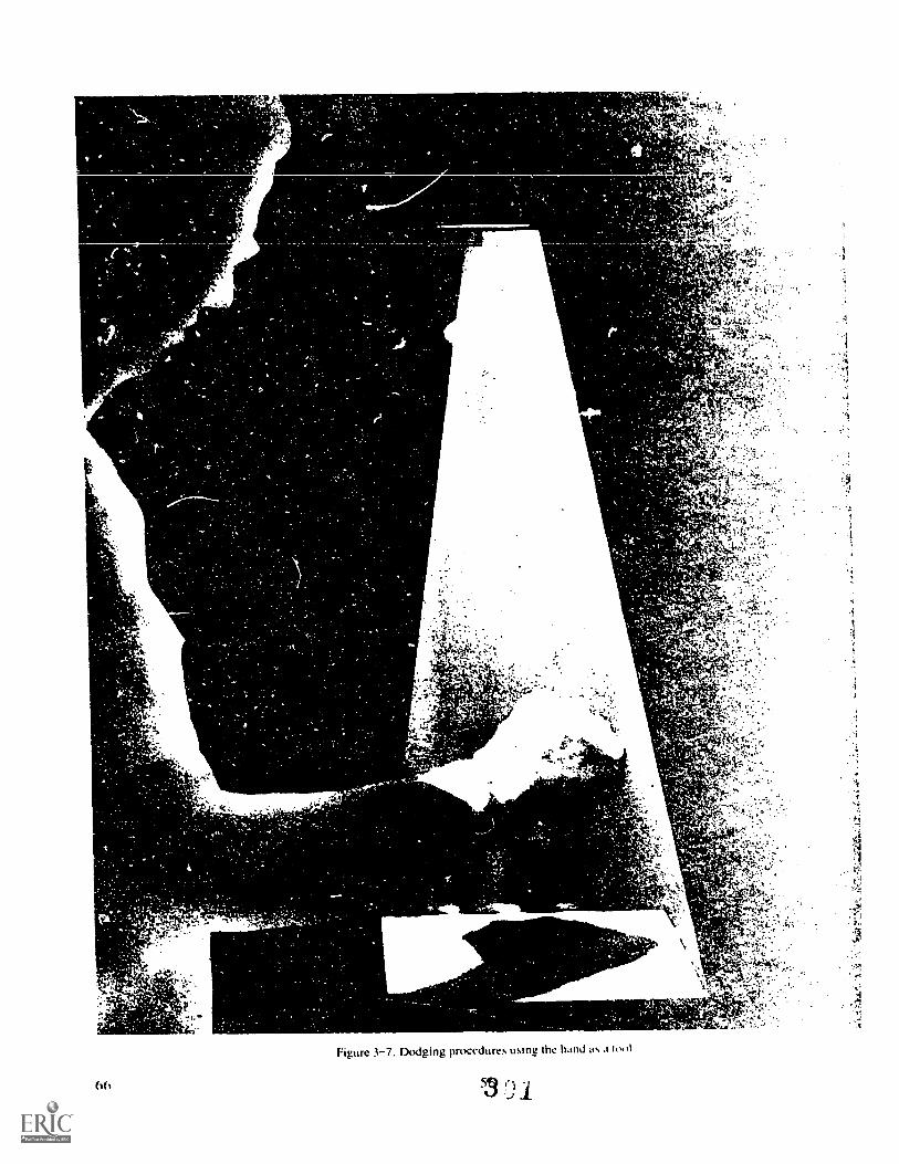
V` s
. i+10,:. ,
f t- '.f.._
4,r. , -,; . ..-
Y t;e:
4
AA. sit
,
:
% C .st,t".17,'
'CArtrAv
of,e,kr4 :
"
.stP'14."!#A.:"1- :
: -
f4r5.715..:
Figure 3-7. Dodging procedures using the hand as a
53 n
".,
7,3,4.;;
f750,:7,-.e
%4' '
"
.1.. '
AS1
e
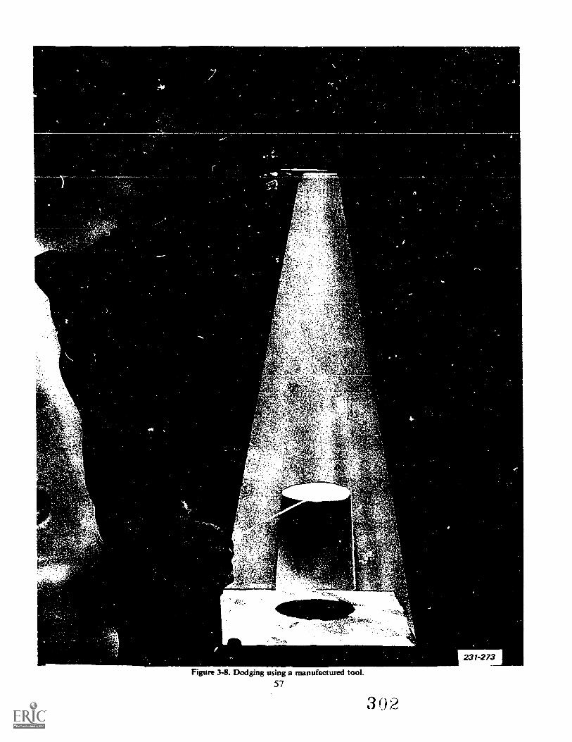
Z-
,r4
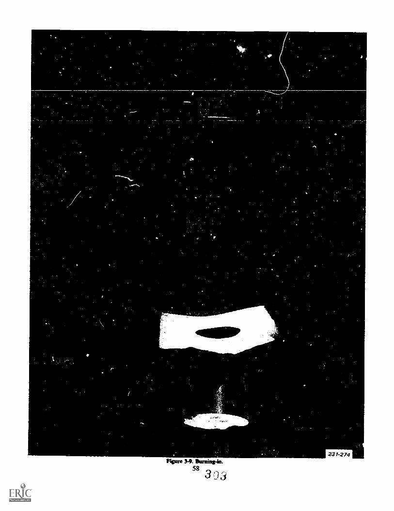
^1.
nt-
231-274Rsure 3-9. Burning-en.
583 !-.)3
h. Horizontal, vertical, or diagonal lines shouldnever be allowed to cut the picture in equal parts. Forexample, the horizon should be below or above thecenter of the picture.
c. The horizon should be level.d. Live subjects should be looking into the picture.
not out of it. In other words, there should be morespace in front of the figure than behind it. This princi-ple also applies to action photographs: your composi-tion is stronger if the action leads into the photographand weaker is it leads out of it.
e. Let the subject determine whether it should beprinted vertically or horizontally. Tall, thin subjects,such as portraits or buildings, work best vertically.Wide subjects, such as scenics, print better hori-zootally. If you have doubts, print it both ways andthen decide.
To have clear idea what the best approach wouldbe, make a MI-size test print. After processing andfinishing, place the print under normal illuminationand use L-shaped "rulers" to crop the picture. (TheL-shaped cropping guides can be made from card-board, etc.) Adjust the rulers until the image is the wayyou want it and then with a grease pencil, mark thepicture. This indication then can be used when youmake your final print. (Remember that when youchange the image size of.the print, you must make newtest strips to determine the proper exposure, etc.)
Once you have decided what you want to do, thenyou can apply a number of different techniques.
The basic technique is to change the size of theimage by changing the printer head/ paper relationship.As the distance increases, the image becomes larger.
Another way to change image size is to change thefocal length of the printing lens. The shorter the focallength, the larger the image for a given negative size.
Another technique involves the use of the easel. Theeasel can be placed horizontally or vertically any-where within the projected image. It can also be laidat different angles to straighten a horizon line. If youhave easels with adjustable blades and you are notheld to a certain overall image size, you can crop byadjusting the blades.
NOTE: While not fitting within the topic of com-position per se, remember that the tone and contrastof the image greatly affects the way people see yourcomposition.
Exercises (650):1. How should the horizon line appear in a print?
2. How should live subjects be arranged?
3. What are L-shaped rulers used for?
4. When should you switch to a printing lens with ashorter focal length?
59
5. What should determine whether the print is hori-zontal or vertical?
3-9. Distortion ControlEvery photographer has discovered what is bound to
happen if he tilts his camera upwards while taking apicture of a tall buildingthe vertical lines convergeand the walls seem to be on the point of collapsing. Inthis section, we are not going to review how to shootsubjects like tall buildings, but we are going to describehow to correct for distorted images when you projec-tion print. (No such correction is possible by normalcontact printing.)
651. State the proper techniques to use when you mustcorrect for distortion during projection printing.
A viewing camera is equipped with adjustments thatpermit making the film nearly parallel with the subjectin spite of viewpoint. However, the press-type camerahas only a rising front and a lateral shift of the frontstandard to accomplish any corrective action. Minia-ture and roll-film cameras rarely have means fcr cor-recting the alignment of the film and the subject. As aresult of these 1,mitations in taking the photograph,many negatives show a noticeable convergence of linesthat is distracting. Changes in these images can beproduced by manipulation of the projection printer toachieve the desired correction.
The control of distortion is based on the fact thatimage size varies with the distance between the nega-tive and the easel. The greater the distance betweenthe negative and the easel, the larger the size of theimage produced. Thus, if the image is projected uponan inclined plane or the image is projected from aninclined negative, the portion of the image farthestfrom the negative will have the largest image size.
Conversely, that portion of the image being closestto the negative will have the smallest image size. If anegative consisting of parallel lines 1vere to be pro-ject( d from an inclined negative or onto an inclinedplane, all portions of the negative would not be thesame distance from the paper, and the lines would notbe recorded as parallel. By the same token, a negativethat has lines not parallel (within limits) could be pro-jected so that the print will show them as parallel.The control of distortion is limited to some extent bythe type of projection equipment available for makingthe print.
304
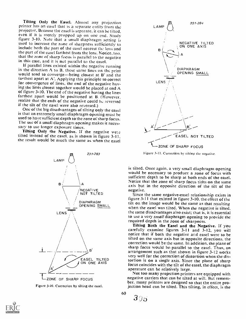
Tilting Only the Easel. Almost any projectionprinter has an easel that is a separate entity from theprojector. Because the easel is separate, it can be tilted,even if it is merely propped up on one end. Studyfigure 3-10. Note that a small diaphragm setting isused to increase the zone of sharpness sufficiently toinclude both the part of the easel nearest the lens andthe part of the easel farthest from the lens. Notice, too,that the zone of sharp focus is parallel to the negativein this case, and it is not parallel to the easel.
If parallel lines existed within the negative runningin the direction A to B, these same lines on the printwould tend to convergebeing closest at B' and thefarthest apart at A'. Applying this principle to correctfor convergence of lines, the end of the negative hav-ing the lines closest together would be placed at end Aof figure 3-10. The end of the negative having the linesfarthest apart would be positioned at B. (However,realize that the ends of the negative could t)L reversedif the tilt of the easel were also reversed.)
One of the big disadvantages of tilting only the easelis that an extremely small diaphragm opening must beused to have sufficient depth to the zone of sharp focus.The use of a small diaphragm opening makes it neces-sary to use longer exposure times.
Tilting Only the Negative. If the negative weIetilted instead of the easel, as is shown in figure 3-11,the result would be much the same as when the easel
231-283
LAMP
\ A
/NEGATIVENOT TILTED
DIAPHRAGMOPENING SMALL
LENS
EASEL TILTEDON ONE AXIS-------
LZONE OF SHARP FOCUS
Figure 3-10. Correction by tilting the easel.
60
LAMP O, 231-284
NEGATIVE TILTEDON ONE AXIS
Be--",.
A
DIAPHRAGMOPENING SMALL
LENS /'
EASEL NOT TILTED
--C---ZONE OF SHARP FOCUS
Figure 3-11. Correction by tilting the negative.
is tilted. Once again, a very small diaphragm openingwould be necessary to produce a zone of focus withsufficient depth to be sharp at both ends of the easel.Notice that the zone of sharp focus titlts on the sameaxis but in the opposite direction of the tilt of thenegative.
Since the same negative-easel relationship exists infigure 3-11 that existed in figure 3-10, the effect of thetilt on the image would be the same as that resultingwhen the easel was tilted. When the negative is tilted,the same disadvantages also exist; that is, it is essentialto use a very small diaphragm opening to provide therequired depth in the zone of sharpness.
Tilting Both the Easel and the Negative. If youcarefully examine figures 3-11 and 3-12, you willnotice that if both the negative ar.d easel were to betilted on the same axis but in opposite directions, thecorrection would he the same. In addition, the plane ofsharp focus would be. parallel to the easel. Thus, anarrangement such as that shown in figure 3-12 worksvery well for the correction of distortion when the dis-tortion is on a single axis. Since the plane of sharpfocus coincides with the tilt of the easel, the diaphragmaperature can be relatively large.
Not too many projection printers are equipped withnegative carriers that can be tilted at will. But remem-ber, many printers are designed so that the entire pro-jection head can be tilted. This tilting, in effect, is the
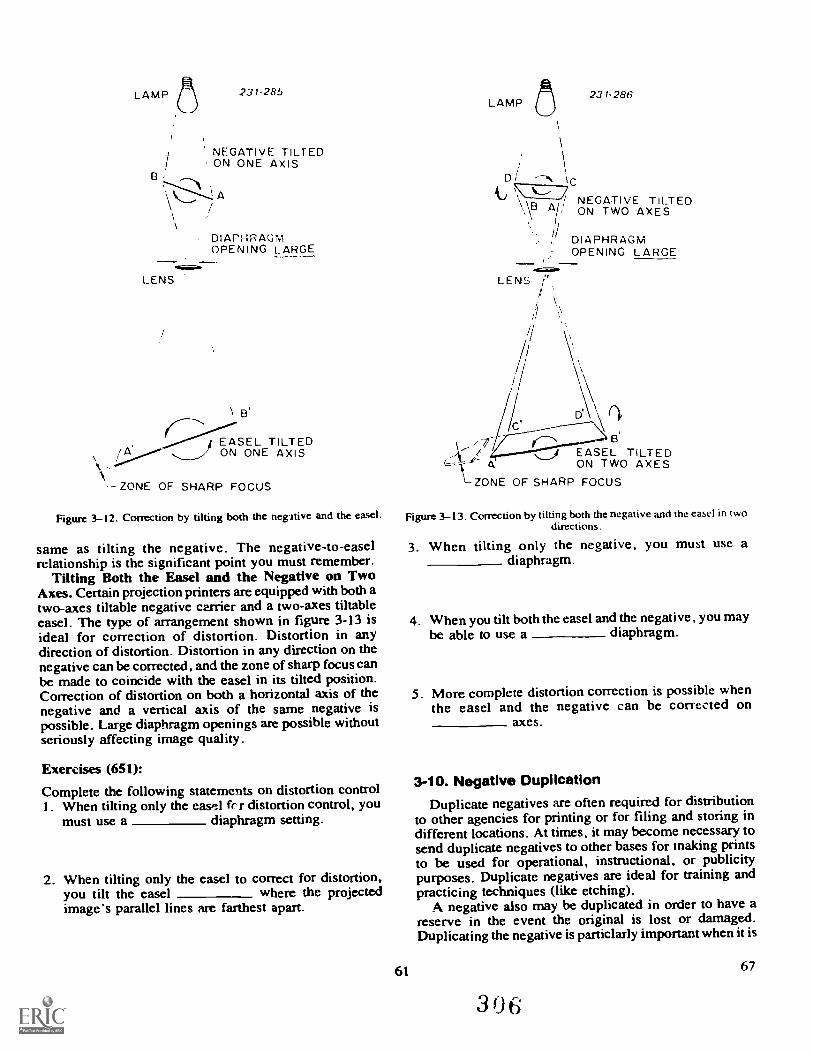
LAMP 231- 285
NEGATIVE TILTEDON ONE AXIS
DIAPHRAGMOPENING LARGE_ _
LENS
/ EASEL TILTEDON ONE AXIS
k
- ZONE OF SHARP FOCUS
Figure 3-12. Correction by tilting both the negrtive and the easel.
same as tilting the negative. The negative-to-easelrelationship is the significant point you must remember.
Tilting Both the Easel and the Negative on TwoAxes. Certain projection printers are equipped with both atwo-axes tiltable negative carrier and a two-axes tiltableeasel. The type of arrangement shown in figure 3-13 isideal for correction of distortion. Distortion in anydirection of distortion. Distortion in any direction on thenegative can be corrected, and the zone of sharp focus canbe made to coincide with the easel in its tilted position.Correction of distortion on both a horizontal axis of thenegative and a vertical axis of the same negative ispossible. Large diaphragm openings are possible withoutseriously affecting image quality.
Exercises (651):
Complete the following statements on distortion controlI. When tilting only the easP.:1 r distortion control, you
must use a diaphragm setting.
2. When tilting only the easel to correct for distortion,you tilt the easel where the projectedimage's parallel lines are farthest apart.
LAMP (7)1
DI
231- 286
C/ NEGATIVE TILTED
ON TWO AXES
DIAPHRAGMOPENING LARGE
LENS
D\\____)/ EASEL TILTED
ON TWO AXES\--ZONE OF SHARP FOCUS
Figure 3-13. Correction by tilting both the negative and the easel in twodirections.
3. When tilting only the negative, you must use adiaphragm.
4. When you tilt both the easel and the negative, you maybe able to use a diaphragm.
5. More complete distortion correction is possible whenthe easel and the negative can be corrected on
axes.
3-10. Negative DuplicationDuplicate negatives are often required for distribution
to other agencies for printing or for filing and storing indifferent locations. At times, it may become necessary tosend duplicate negatives to other bases for making printsto be used for operational, instructional, or publicitypurposes. Duplicate negatives are ideal for training andpracticing techniques (like etching).
A negative also may be duplicated in order to have areserve in the event the original is lost or damaged.Duplicating the negative is particlarly important when it is
61 67
3 06
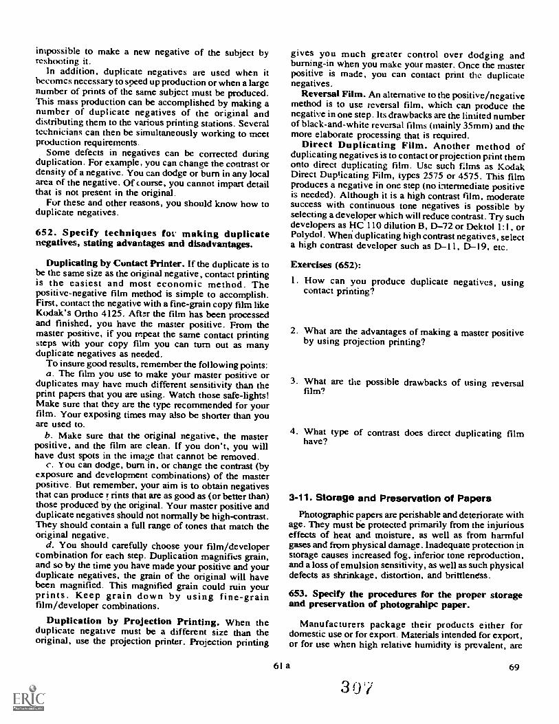
impossible to make a new negative of the subject byreshooting it.
In addition, duplicate negatives are used when itbecomes necessary to speed up production or when a largenumber of prints of the same subject must be produced.This mass production can be accomplished by making anumber of duplicate negatives of the original anddistributing them to the various printing stations. Severaltechnicians can then be simultaneously working to meetproduction requirements.
Some defects in negatives can be corrected duringduplication. For example, you can change the contrast ordensity of a negative. You can dodge or burn in any localarea of the negative. Of course, you cannot impart detailthat is not present in the original.
For these and other reasons, you should know how toduplicate negatives.
652. Specify techniques for.. making duplicatenegatives, stating advantages and disadvantages.
Duplicating by Contact Printer. If the duplicate is tobe the same size as the original negative, contact printingis the easiest and most economic method. Thepositive-negative film method is simple to accomplish.First, contact the negative with a fine-grain copy film likeKodak's Ortho 4125. After the film has been processedand finished, you have the master positive. From themaster positive, if you repeat the same contact printingsteps with your copy film you can turn out as manyduplicate negatives as needed.
To insure good results, remember the following points:a. The film you use to make your master positive or
duplicates may have much different sensitivity than theprint papers that you are using. Watch those safe-lights!Make sure that they are the type recommended for yourfilm. Your exposing times may also be shorter than youare used to.
b. Make sure that the original negative, the masterpositive, and the film are clean. If you don't, you willhave dust spots in the image that cannot be removed.
c. Y ou can dodge, burn in, or change the contrast (byexposure and development combinations) of the masterpositive. But remember, your aim is to obtain negativesthat can produce r rints that are as good as (or better than)those produced by the original. Your master positive andduplicate negatives should not normally be high-contrast.They should contain a full range of tones that match theoriginal negative.
d. You should carefully choose your film/developercombination for each step. Duplication magnifies grain,and so by the time you have made your positive and yourduplicate negatives, the grain of the original will havebeen magnified. This magnified grain could ruin yourprints. Keep grain down by using fine-grainfilm/developer combinations.
Duplication by Projection Printing. When theduplicate negative must be a different size than theoriginal, use the projection printer. Projection printing
gives you much greater control over dodging andburning-in when you make your master. Once the masterpositive is made, you can contact print the duplicatenegatives.
Reversal Film. An alternative to the positive/negativemethod is to use reversal film, which can produce thenegative in one step. Its drawbacks are the limited numberof black-and-white reversal films (mainly 35mm) and themore elaborate processing that is required.
Direct Duplicating Film. Another method ofduplicating negatives is to contact or projection print themonto direct duplicating film. Use such films as KodakDirect Duplicating Film, types 2575 or 4575. This filmproduces a negative in one step (no intermediate positiveis needed). Although it is a high contrast film, moderatesuccess with continuous tone negatives is possible byselecting a developer which will reduce contrast. Try suchdevelopers as liC 110 dilution B, D-72 or Dektol 1:1, orPolydol. When duplicating high contrast negatives, selecta high contrast developer such as DI 1, D-19, etc.
Exercises (652):
I. How can you produce duplicate negatives, usingcontact printing?
2. What are the advantages of making a master positiveby using projection printing?
3. What are the possible drawbacks of using reversalfilm?
4. What type of contrast does direct duplicating filmhave?
3-11. Storage and Preservation of Papers
Photographic papers are perishable and deteriorate withage. They must tie protected primarily from the injuriouseffects of heat and moisture, as well as from harmfulgases and from physical damage. Inadequate protection instorage causes increased fog, inferior tone reproduction,and a loss of emulsion sensitivity, as well as such physicaldefects as shrinkage, distortion, and brittleness.
653. Specify the procedures for the proper storageand preservation of photograhipc paper.
Manufacturers package their products either fordomestic use or for export. Materials intended for export,or for use when high relative humidity is prevalent, are
61 a 69
30'i

packaged in moisture-proof containers. Packaging forexport is so labeled on individual units as well as on theshipping cartons. Materials intended for nonnal domesticuse may be packaged in moisture-iesistant, but not inwater-tight or vaportight containers. Assume that anunlabeled package is intended for domestic use, and
70
handle it accordingly. Do not keep sensitized papersunder refrigeration once the sealed package has beenbroken, unless the refrigerator can be held at 50 to 60percent relative humidity.
Store individual packages of paper on end so that theweight of the contents is on the edges of the pt.per.
3 , 362
Also, store material with the earliest expiration date tothe front of the stack--this procedure enables you touse the oldest material first. However, when it isknown that the paper due to be used next (accordingto the earliest expiration date) has been shipped orstored under unfavorable conditions, you should setthis material aside and use fresh material for anyhighly ::ritical project you have to print.
Paper removed from cold storage areas must be
adjusted to room temperature over a period of at least8 hours prior to use; longer times are required forwarmup if the packages arc stacked.
Processed prints require the same careful protectionthat processed negatives should receive. Moisture,light, heat, chemical fumes, and careless handling cancause permanent damage. Prints should be carefullyfiled in manila envelopes that are kept in appropriatestorage vaults in an air-conditioned room. The relativehumidity should be kept between 40 to 50 percent andthe temperature near 70° F. (2 i° C.).
Exercises (653):Complete the following statements on the storage andpreservation of photographic paper:I. Packages of paper should be stored so that the
weight of the contents is on the ofthe paper.
2. Older paper should be stored towards theof the stack.
3. Paper removed from storage needs to be ajusted toroom temperature over a period ofhours prior to use.
4. Processed paper needs to be protected from
and
5. Prints should be stored in a room having a tempera-ture near
3-12. Operator MaintenanceIn addition to all the other potential problems in
the darkroom, there is the possibility that equipment
will not work. To make sure that your equipmentworks well, you practice operator maintenance.
654. Specify the proper procedures for operator main-tenance on printing equipment.
In your printing room you have equipment that mustwork properly and consistently. Consider a timer thatoccasionally takes one minute, sometimes one minuteand ten seconds to do a full circle. Not very consistent,is it? You may have a projection printer that slidesdown thc track because of a loose lockinti screw. Itwould be difficult to produce a good print while thelens assembly was moving to the easel. A contactprinter with a hole in the platen will not produce verysharp prints.
As in so many other areas, operator maintenance ofprinting equipment is basically common sense andgood housekeeping.
A contact printer must be kept clean. You shouldcheck to see if each bulb is working. Replace thosetht are burned out. While you are checking for goodbulbs, check the operation of each switch. Identifythose that do not work and have them repaired bymaintenance people. Make sure each piece of electicalequipment is properly grounded. The platen must holdair. Check it for leaks or cracks.
Projection printers also need to be checked forproper operation. Look for loose nuts, bolts, andscrews that you can tighten yourself. Make sure thatelectrical cords are not frayed and that each three-prong plug has al. hree prongs. Look at each negativecarrier to see if it is still square and that those withglass do not have broken, chipped, or scratched glass.Burrs in the metal carriers can also scratch your nega-tives. If you find any burrs, file or sand them smooth.Check the lens cones for proper fit. The lens should besecure and clean. Periodically clean the condenserand/ or diffusion glass. Be careful when handling themas they are generally expensive.
Check the timers, both interval and continuous, forproper and safe operation. Electrical work on timersmust be done by qualified people, but you can identifymalfunctions. Keep the timers clean and do not putthem where water and chemicals can be splashed ontothem.
About all you can do for an easel is to be sure thehinges work. Check adjustable easels for free move-ment of the border masks and ensure that they arenot bent.
Keep all of your printing equipment clean. This willkeep it working longer and will give you a better placeto work in.
63
Exercises (654):I. List three things you should check on a contact
printer.
:3

2. What should you look for when you perform opera-tor nlaintenance on negative carriers? tion a timer?
3. What precautions ,,hould vou take when you posi-
64
Black-and-White Finishing
HN ISH NG YOUR prints is ihe final step in theprinting cycle. It includes all of those actions you takeafter the print has been removed from the fixing bath.Your print finishing operations will include washing,glossing, drying, identifying, and mountingall ofthose things needed to put the "finishing" touches onyour prints.
In this chapter we present information that Youshould learn in order to be an efficient print finisher. Athorough knowledge of finishing techniques is neces-sary if you are to turn out high quality prints that meetthe mission requirLments.
4-1. Washing PrintsWashing is an important step to insure a permanent
image. It should never be done in a haphazard manner.You must, therefore, learn proper washing techniquesand then apply them in your work. This section dis-cusses basic principles of washing prints and the use ofmechanical washers.
655. State principles and describe procedures relatedto print washing.
The purpose of washing prints is to remove theresidual chemicals that remain in the emulsion base ofthe paper after development and fixation. Washingdissolves and dilutes the soluble products and elimi-nates them with the disposal of the wash water.Thorough washing of prints is as necessary asthorough washing of negatives. If processing chemi-cals remain in the paper, they will discolor and ruinthe print. Although chemicals diffuse from both thebase and the emulsion of prints during washing, it isnecessary to wash prints longer than the time requiredfor negatives because the fibers and baryta coating ofthe paper absorb the chemicals. (An exception is resin-coated paper, which can be washed in 4 minutes be-cause it does not absorb chemicals at the same rate asother papers.)
Washing Factors. The length of washing time isdependent upon a number of factors. You should con-sider the following:
65
CHAPTER 4
a. Proper fixing. Using partially exhausted fixingbaths that require longer than normal fixing times willrequire longer than normal washing times.
b. Temperature of the water. The higher the watertemperature, the faster the chemicals are diffused.Therefore, you get faster washing times at 75° F. (24°C.) than at 65° F. (1S.5° C.). (Very high temperatureswill damage the emulsion.)
e. Type and weight of the paper. Whether the paper(is or is not) resin-coated affects the washing rate.Resin-coated papers do not absorb the chemicals as dothe normal kinds and therefore wash faster. Theweight of the paper is significant. Double-weightpaper, which is thick and therefore absorbs morechemicals, takes about twice as long as single-weightpaper.
d. Method of washing. Whether you are using traysor mechanical washers will significantly affect thewater exchange rate and hence the washing times.Mechanical washers, in fact, are a necessity for high-vohime washing.
e. ilate of water exchange. The number of completechanges of water to insure that the contaminatedwater is being completely drained away is important.One change every 5 minutes is recommended to insureproper washing.
Amount of agitation. Agitation is essential to in-sure the free flow of water around each print. Theprints must be rotated by hand or tumbled by mechan-ical means so that each print is adequately washed.
g. Use of a hypo clearing agent. 'Fhe rinsing ofprints in a hypo clearing agent for 3 to 5 minutes priorto washing can significantly reduce washing times.There are a number of commercially made hypo elimi-nators, and formulas are also given in the Photo LabIndex. Using these solutions according to directionscan save you much time.
Washing By Trays. Although most washing is doneby mechanical washers (discus.ed later in this section),small groups of prints may be washed in trays. Twodeep trays sh Id used. The size of the trays selectedis determiro by the size and number of prints to bewashed. Both trays should be filled with water. Allprints are then placed emulsion up in one tray. "Fhe
311
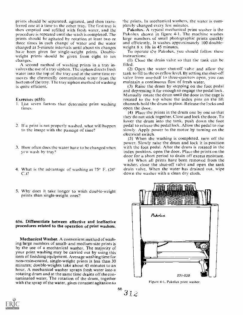
prints should be separated, agitated, and then trans-ferred one at a time to thc other tray. The first tray isthen emptied and refilled with fresh water, and theprocedure is repeated until the wash is completed. Theprints should be agitated by rotation at least two orthree times in each change of water and the waterchanged at 5-minute intervals until about six changeshave been iziven for single-weight prints. Double-weight prints should be given from eight to ten,1Loan& Ls.
A second method of washing prints in a tray in-volves the use of a tray siphon. The siphon directs freshwater into the top of the tray and at the same time re-moves the chemically contaminated water from thebottom of the tray. The tray siphon method of washingis quite efficient.
Exercises (655):1. List seven factors that determine print washing
t imes.
2. I f a print is not properly washed, what will happento the image with the passage of time?
3. How often does the water have to be changed whenvcu wash by tray?
4. What is the advantage of washing at 75° F. (24°C.)?
5. Why does it take longer to vb4sh douhle-weightprints than single-weight ones?
656. Differentiate between effective and ineffectiveprocedures related to the operation of print washers.
Mechanical Washer. A convenient method of wash-ing large numbers of small- and medium-size prints isby the use of a mechanical washer. The majority ofyour print washing may be carried out by using thisitem of finishing equipment. Average washing time fornon-resin-coated, single-weight prints is less than 30minutes; double-weights take about 45 minutes to anhour. A mechanical washer sprays fresh water into arotating drum and at the same time drains off the con-taminated water. The rotation of the drum, togetherwith the spray of the water, gives constant agitation to
66
he prints. In mechanical washers, the water is com-pletely changed every few minutes.
Pakolux. A :ypical mechanical print washer is thePakolux shown in figure 4-1. The machine washeslargc numbers of small photographic prints quicklyand efficiently. It washes approximately 100 double-weight 8 x lOs in 45 minutes.
To operate the Pakolux, you should follow theseinstructions:
(1) Close the drain valve so that the tank can befilled.
(2) Open the water shut-off valve and allow thetank to till to the o\ erflow level. By setting the shut-offvalve from one-half to three-quarters open, vou canmaintain a continuous flow of fresh water.
(3) Raise the drum by stepping on the foot pedaland depressing it far enough to engage the pedal lock.Manually rotate the drum until the door in the cage isrotated to the top where the index pins on the liftchannels hold the drum in place. Release the Ipcks andopen the door.
(4) Place the prints in the drum one by one so thatthey do not stick together. Close and lock the door. Tolower the drum into the tank, push down the footpedal to release the pedal lock. Allow the pedal to riseslowly. Apply power to the motor by turning on theelectrical switch.
(5) When the washing is completed, turn off thepower. Slowly raise the drum and lock it in positionwith the foot pedal. After the drum is rotated in theindex position, open the door. Place the prints on thedoor for a short period to drain off excess moisture.
(6) When all prints have been removed from thewasher, close the shut-off valve and open the tankdrain valve. When the water has drained out, wipedown the washer with a clean dry cloth.
3
Figure 4-1. Pakolux print washer.
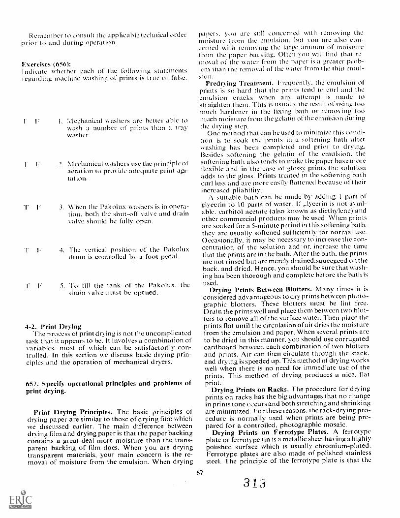
Remember to consult the applicable technical orderprior to and during operation.
Exercises (6561:Indicate whether each of the following statementsregarding machine washing of prints is true or false.
:%.lechanical washers are better able towash a number of prints than a traywasher.
1. NI eehanical washers use the prine;ple ofaeration to provide adequate print agi-tation.
washers is in Opera-tion. both the shut-off valve and drainvalve should be fully orm.
T F 4. The vertical position of the Pakoluxdrum is controlled by a foot pedal.
F 5. To fill the tank of the Pakolux. thedrain valve must be opened.
4-2. Print DryingThe process of print drying is not the uncomplicated
task that it appears to be. It involves a combination ofvariables, most of which can be satisfactorily con-trolled. In this section we discuss basic drying prin-ciples and the operation of mechanical dryers.
657. Specify operational principles and problems ofprint drying.
Print Drying Principles. The basic principles ofdrying paper are similar to those of drying film whichwe discussed earlier. The main difference betweendrying film and drying paper is that the paper backingcontains a great deal more moisture than the trans-parent backing of film does. When you are dryingtransparent materials, your main concern is the re-moval of moisture from the emulsion. When drying
papers. vou are still concerned with r.L.moving themoisture from the emulsion. but vou are also con-cerned with removing the large amount of moisturefrom the paper hat_ king. Often you will find that re-moval of the Wa ter from the parer is a greater prob-lem than the removal of t he water from t he th in eMU I-sio n.
Predrying Treatment. Frequently. the emulsion ofprints is so hard that the prints tend to curl and theemulsion cracks when any attempt is made tostraighten them. This is usually the result of using toomuch hardener in the fixing bath or removing toomuch moisture from the gelatin of the emulsion duringthe drying step.
One method that can be used to minimize this condi-tion is to soak the prints in a softening bath afterwashing has been completed and prior to drying.Besides softening the gelatin of the emulsion, thesoftening bath also tends to make the paper base moreflexible and in the case of glossy prints the solutionadds to the gloss. Prints treated in the softening bathcurl less and are more easily flattened because of theirincreased pliability.
A suitable bath can be made by adding I part ofglycerin to 10 parts of water. F ..tycerin is not avail-able. carbitol acetate (also known as diethylene) andother commercial products may be used. When printsare soaked for a 5-minute period in this softening bath.they are usually softened sufficiently for normal use.Occasionally, it may be necessary to increase the con-centration of the solution and:or. increase the timethat the prints are in the bath. After the bath, the printsare not rinsed but are merely drained.squeeizeed on theback, and dried. El ence. you should bc sure that wash-ing has been thorough and complete before the bath isused.
Drying Prints Between Blotters. Many times it isconsidered advantageous to dry prints between photo-graphic blotters. These blotters must be lint free.Drain the prints well and place them between two blot-ters to remove all of the surface water. Then place theprints flat until the circulation of air dries the moisturefrom the emulsion and paper. When several prints areto be dried in this manner, you should use corrugatedcardboard between each combination of two blottersand prints. Air can then circulate through the stack,and drying is speeded up. This method of drying workswell when there is no need for immediate use of theprints. This method of drying produces a nice, flatprint.
Drying Prints on Racks. The procedure for dryingprints on racks has the big advantages that no changein prints tone occurs and both stretching and shrinkingare minimized. For these reasons, the rack-drying pro-cedure is normally used when prints are being pre-pared for a controlled, photographic mosaic.
Drying Prints on Ferrotype Plates. A ferrotypeplate or ferrotype tin is a metallic sheet having a highlypolished surface which is usually chromium-plated.Ferrotype plates are also made of polished stainlesssteel. The principle of the ferrotype plate is that the
67
3 1 ti
surface of the wet glossy-surfaced print is pressedagainst the surface of the plate. As the print dries. ittakes on the exceptionally smooth surface of the ferro-type plate. Because of the extremely high polish of agood ferrotype plate, the print dries with a very highgloss. The procedure used is to take the wet print thathas l,een fully washed and treated in the glossing or501(211111g solution and place it on the ferrotype plate.The emulsion of the print must he facing the glossysurface of the ferrotype tin. When the print is in thisposition use a squeegee or print roller to remove all ofthe excetis water and any air bubbles. After the print isin good contact with the plate. it is allowed to dry.When the print is drv. it usually falls away from theplate. (Occasionall, a print may not fail oil: but. bylifting one corner with the fingernail, it becomesfree and falls away.)
The polished surface of ferrotype plates must heabsolutely clean and free of scratches. Any dust. dirt.lint, or other foreign matter on the surface of the plateis transferred to the surface of the dried print. Clean-liness and care of ferrotype plates is absolutely es-sential.
Common Problems Encountered in Print Drying.Some of the problems encountered in print dr ing aretied directly to specific drying methods. but otherproblems are common to all print dryinu. Let us dis-cuss some of the common print drying problems.
Curl. As a print dries, the gelatin shrinks. The moreit shrinks, the greater the tendency for curling. Thecurl is actually caused by the gelatin shrinking morethan the paper backing. The most effective method ofpreventing curl is to dry the print in either anabsolutely flat position or a position that causes theemulsion to be stretched: that is. in a position that isreverse to the curl inherent in the paper. If the print isallowed to dry in this position, the tendency to curl isminimi/ed.
I n eN tremely dry climates. you may need to use flat-tening solutions that help the gelatin to retain itsmoisture content. If you soak thc prints for sufficienttime to allow the flattening solution to thoroughlysaturate both thc emulsion and the paper before youdry the prints, you :In keep curling at a minimum.
Shrinkage. "I- he problem of shrinkage is not im-portant for ordinary prints, but when the prints mustbe used for taking measurements or for assemblingcontrolled mosaics (e.g.. maps). shrinkage becomesvery serious. Print shrinkage is caused by gelatin con-traction and or paper contraction. The contractionmakes the print surface occupy less area than it did atthe time it was exposed. Dimensional accuracy canbest be achieved by dryina the prints slowly and by notsubjecting them to any stress before. during, or follow-ing the drying process. When they are available, usespecial dimensionally stable papers.
Cracks. If the emulsion of a print contains cracks, itvery often indicates that there has been rough handlingof the material. The improper handling may havetaken place before exposure, during processing,during drying, or subsequent to drying. If t he emulsion
of the paper contains the right amount of moisture, itcan take a great deal of flexing without cracking. How-e\ er. if the moisture content drops below normal, thegelatin becomes quite brittle and may crack when it isbent. Excessive hardening of the emulsion and dryingat too high a temperature may cause the gelatin tocrack more easily. Cracks can result when a printstraightener. which bends the print in a reverse curlaround a roller. is set to bend the material too sharply.
Chan.Qe in tone (plumming)- When Photographicpapers arc dried by heating, they may change tone.I hey tend to change toward a colder, more purplecolor. .Ifre effect is dependent upon the amount of heatused, the nature of the sensiti/ed materials, and thetone of the image prior to drying. I o prevent plum-ming. your prints can be soaked in an antiplummingsolution prior to (frying.
Changes ni the appearance of the print surtace.When matte and semimatte papers are dried by heat.the surfaces sometimes have a higher sheen than if theyare dried naturally. Starch grains are included in theemulsion to provide matting. l'he rising temperatureof the paper causes these grains to burst. While thiseffect may i Ill prove t he a p pea ra rice of some sem i ma t t epapers. it is normally considered detrimental for printson most matte papers.
NO FE: You will probably find Ciat the new resin-coated printing papers are free from many of the printdrying problems we have discussed.
Exercises (657):COM Plet e the following statements related to the prin-ciples and problems of print drying.1. Drying prints takes longer Iha n drying film because
prints have a
2. A suitable softening and Ltlossing bath can be madeby adding I part of toparts of water.
3. Drying prints on racks minimi/esand
4. A metallic sheet havinu a highly polished chromesurface is called a
5. When the gelatin of the paper shrinks faster thanthe paper. the resulting print will have
6. A solution is used indry climates to help the gelatin retain moisture.
68-)
(4t
7. lf the emulsion becomes too dry, the paper is likelyto when bent.
8. Shrinkage is a serious problem in prints being usedto make
9. is a c'-ange in the print tone, usuallyresulting from drying with heat.
658. Specify operational characteristics and pro-cedures for print dryers.
You will dry the majority of your prints by usingmechanical dryers. Therefore, we cover the operationof a typical belt dryer suitable for all your conven-tional prir ..rying needs. You should note that whenyou are printing with resin-coated paper, the printsshould be air dried or you should use the new types ofdryers designed for resin-coated papcin e>r) GOA
Belt Dryers. The majority of printurrt`ered on themotor-driven, belt-type dryer. A belt'elryer consists ofa drUnl, ovir which a wide, endless cloth belt or aprontravels. The drum is motor-driven and is heated byelectricity or hot water. The drying rate for prints isregulated by the temperature of the drum and thespeed at which the drum rotates. The drum tempera-ture is controlled by a thermostat, while the drumrotation speed is regulated with a variable-speedmotor control and a speed reduction system. Theprints are held in contact with the drum by means ofthe belt and are dried in one revoiution of the drum.
The Pakonomy Print Dryer, Model 26W. ThePakonomv Print Dryer, shown in figure 4-2, is typicalof the print dryers found in base laboratories. Let usdiscuss its operation as an example of dryer operation.
General procedure. To start the dryer, turn on thedrive end heater switches. When the dryer is up to theproper operating temperature, prints may be placedon the apron for drying. It is best to run a few trialprints first to establish a suitable setting for produc-tion prints. Glossy prints are placed on the apronemukion side up; matte prints, emulsion side down.
A pilot light is provided to indicate when the heateris operating. This light goes out when the heater at-tains the desired temperature setting. Two thermostatsare provided: a control thermostat for manual settinuof the required operating temperature, and a safetythermostat inside the heater unit, which prevents dam-age in the event of the failure of the control thermo-stat. The safety thermostat is preset at the factory atapproximately 200° F. (94° C.), and no further adjust-ment is required.
Figure 4-2. Pakonomy print dryer.
V14 4 it) di-te -gag pY 4ae placte4For normal operation. set the control thermostat to
190° F. (88.5° C.) for the initial run. Subsequentexperience will suggest variations, in conjunction withapron speed, to secure optimum performance undervariables of paper weight and humidity.
The water circulating unit, containing the heater, isprovided with an ON-OFF switch and a thermostatictemperature control. The motor drive unit has a simi-lar ON-OFF switch and a rheostat speed control.
Wit h the heater switch ON, the heatiniz element s a reon until 1.1ic drum temperature reaches the level set bythe ,!ontrol dial. The control thermostat then auto-matically turns the elements on and off to maintain therequired temperature.
Apron tracking adjustment. Before starting up thedryer the first time, it is advisable to check out theapron tracking adjustment. Insure that the dryer isstanding square and level. th:n proceed as follows:
( I) Turn on the drive motor switch.(2) Set the collars on the apron guide shah to allow
a 1 4-inch (6mm) clearance for each edge of the apron.(3) When running. the apron will slowly drift away
from the tight side. Correct this drift by turning theadjusting screw on the right table arm.
(4) When the apron appears to be centered. ruil thedryer for an hour to see whether further tine adjust-ment is needed.
(5) Should the squeegee roller rub on the leverbracket. you can remedy the problem by compress*the collars on the ends of the roller to secure the neces-sary running clearance. Avoid excessive compression.as this may cause a fiat spot in the roller.
69
3
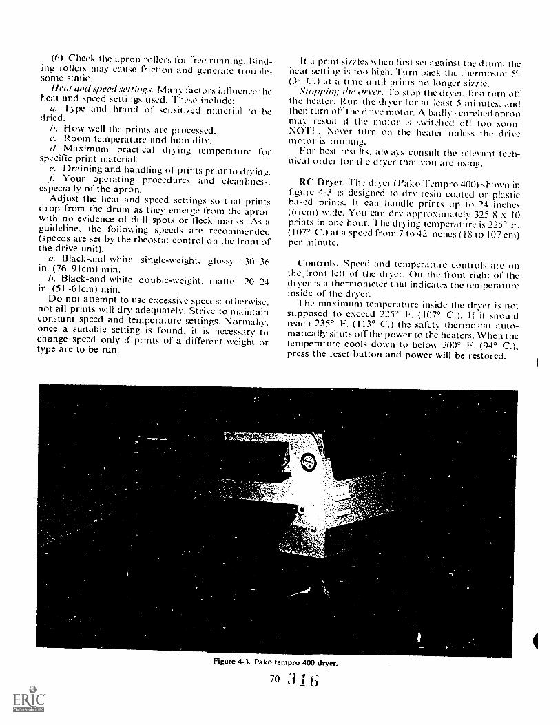
(6) Check the apron rollers for free running. Bind-ing rollers may cause friction and generate trouole-some static.
Heat and speed settings. Many factors influence theheat and speed settings used. These include:
a. Type and brand of sensitind material to hedried.
h. How well the prints are processed.e. Room temperature and humidity.d. Maximum practical drying temperature for
sp:cific print material.e. Draining and handling of prints prior to drying.
Your operating procedures and cleanliness,especially of the apron.
Adjust the heat and speed settings so that printsdrop from thc drum as they emerge from the apronwith no evidence of dull spots or fleck marks. As aguideline, the following speeds are recommended(speeds are set by the rheostat control on the front ofthe drive unit):
a. Black-and-white single-weight, iflossy 30 36in. (76-91cm) min.
h. Black-and-white double-weight, matte 10 14in. (51-61cm) min.
Do not attempt to use excessive speeds: otherwise,not all prints will dry adequately. Strive to maintainconstant speed and temperature settings. Normally,once a suitable setting is found, it is necessary tochange speed only if prints of a different weight ortype are to be run.
If a print sit/les when first set against the drum, theheat setting is too high. Turn back the thermostat 5'(3' C.) at a time until prints no longer siltle.
.Vwpping the dryer. To stop the dryer, first turn offthe heater. Run the dryer for at least 5 minutes, iindthen turn off t he drive motor. A badly scorched apronmay result if the motor is switched off too soon,NOT1 : Never turn on the heater unless the drivemotor is running.
For best results, always consult the relevant tech-nical order for the dryer that you are usine.
RC Dryer. The (1 ryer ( Pa k o 'Fernpro 400) s hown infigure 4-3 is designed to dry resin coated or plasticbased prints. lt ean handle prints up to 24 inches;6Iem) wide. You can dry approximately 325 8 x 10prints in one hour. The drying temperature is 225° F.(107° C.) at a speed from 7 to 42 inches (18 to 107 cm)per minute.
Controls. Speed and temperature controls are onthe.front left of the dryer. On the front right of thedryer is a thermometer that indicatL-s the temperatureinside of the dryer.
The maximum temperature inside the dryer is notsupposed to exceed 225° F. ( 107° C.). If it shouldreach 235° F. (113° C.) the safety thermostat auto-matically shuts off the power to the heaters. When thetemperature cools down to below 200° F. (94° C.).press the reset button and power will be restored.
Figure 4-3. Pako tempro 400 dryer.
70 3 6

Opening and eh-sing the sliding cover operates themain switch, which controls all of the electrical Cir-cuits. You should not use the temperature control asan on off switch for the heaters.
General Procedures. To start the dryer, all you haveto do IS Close the sliding cover. Allow 15 to 20 minutesfor the dryer to warm up.
Heat aml speed settings. With most RC' papers, youneed to set the temperature control at 6.5 and the speedcontrol at 3.5. Experience will allow you to get thebest combination of heat and speed. If the temperatureis too low, the prints will not dry in a sinale passthromth the dryer. If the temperature is too high. theprints will have excessive curl. Change the speed andtemperature until the prints are dry and flat as theycome out of the dryer.
Operation. To dry your prints using this dryer, fol-low these steps.
Close the cover.2. Set the speed and temperature.3. When the temperature reaches 180° F. (83° C.)
start feeding the prints in emulsion up.4. Watch the prints through the window to be sure
they are not curling. Check the prints in the re-ceiving tray to be sure they are dry.
Standby. If the dryer is to be idle for a few minutesto an hour, you can lower the temperature to 140° F.(60° C.). This will conserve electrical power.
Shut ail: When you are done drying prints, simplyopen the door. Wipe off the rollers with a clean, dampsporwe or cloth.
Exercises (658):Complete the following statements related to printdryer operation:
I. Matte prints should be placed emulsion side _on the apron.
2. Glossy prints should be placed emulsion sideon the apron.
3. Glossy prints are dried at a ratethan matte prints.
4. The pilot light on the Pakonomy dryer goes outwhen the heater reaches the
5. Electrically heated is the PakonomyDryer's source of heat.
71
6. roller may cause apron frictionand g.merate static electricity.
7. l'he drive motor should continue to run after thehas hcen turned off.
8. Roomfeet your heat and sr. ed settings.
e PLIkt, Tempro 400 dryer can dry prints up toinches wide.
10. lithe dryer temperature gets too high. theshuts off the power to the
II and ale Cover oper-ates the main switch.
12. Prints should be andwhen they come out of the dryer.
4-3. Mounting PrintsFor exhibition, display, and handling purposes, a
print is usually mounted on a stiff board that sets offthe picture by a broad border and also protects theedges of the print itself against damage.
659. State principles related to print mounting anddescribe procedures and materials that are used tomount prints.
Mounting Principles. In preparing a.print for exhi-bition or display, the objective is to show the print tobest advantage. Simplicity is essential in doing this.Any elaborate artwork, such as colored borders orfancy lettering, often detracts from the main point ofinterest, which, of course, is the print image.
Prints for display purposes are generally mountedon special cardstock to make them stand out fromtheir surroundings. The cardstock is available invarious sizes, colors, textures, and weights. While nodefinite rules can be given, vou should use a mountthat compliments the print. The mount should be large
31/
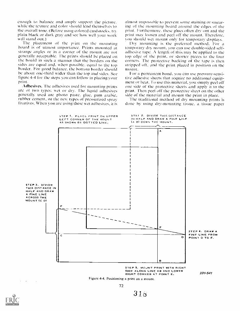
enough to balance and amply support the picture.while the texture and color should lend themsck es tothe overall tone. (Before USWw colored cardstocks. tryplain black or dark gray and see how well your workwill stand out.)
The placement of the pHnt on the mountingboard is of utmost importance. Prints mounted atstrange angles or in a corner of the mount arc notunerally acceptable. The prints should be placed onthe board in such a manner that the borders on thesides are equal and, \\Alen possible. equal to the topborder. For good balance. the bottom border shouldbe about one-third wider than the top and sides. Seefigure 4-4 for the steps you can follow in placing yourprint.
Adhesives. The adhesives used for mounting printsare ot two types: wet or dry. l'he liquid adhesivesgenerally used arc photo paste, glue, gum arabic,rubber cement, or the new types of pressuri/ed sprayfixatives. When you are using these wet adhesives, it is
STEP 3. DIVIDETHIS DISTANCE INHALF AND DRAWA FINE LINEACROSS THEMOUNT (C Dl
STEP I, PLACE PRINT ON UPPERLEFT CORNER OF THE MOUNTAS SHOWN BY DOTTED LINE.
almost impossiNe to prevent some staining or smear-ing of the mounting hoard around the edges of theprint. Furthermore. these glues often dry out and theprint may loosen and peel off the mount. Therefore,you should wet mount only for temporary d isplavs.
Dry mounting is the preferred method. For atemporary dry mount, you can use double-sided self-adhesive tape. length of this may be applied to thetop edge of the print, or shorter pieces to the fourcorners. The protective backing of the tape is thenstripped oft. and the print placed in position on themount.
For a permanent bond, you can use pressure-sensi-tive adhesive sheets that require no additional equip-ment or heat. To use this material, you simply peel offone side of the protective sheets and apply it to theprint. Then peel off the protective sheet on the otherside of the material and mount the print in place.
.1 he traditional method of dry mounting prints isdone by usini2, (lry-mounting tissue, a tissue paper
STE!' 2. DIVIDE THIS DISTANCEIN HALF AND DRAW A FINE LINE(A 13) DOWN THE MOUNT.
F
I
I
I
I
i
II
A
I
I
I
I
I
I
I
I
I
I
I
I
1
I
I
I
I
I
----......-"----......
------.........._E
C
B
D
STEP 5. MOJNT PRINT WITH RIGHTSIDE ALONG LINE AB AND LOWERRIGHT CORNER AT POINT E.
Figure 4-4. Positioning a print on a mount.
72
3 'r
STEP 4. DRAW AFINE LINE FROMPOINT D TO F.
231-541
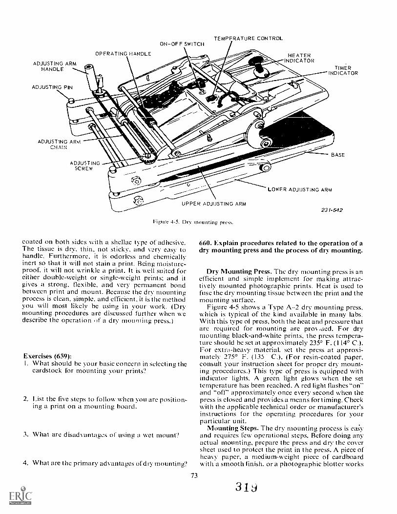
ADJUSTING ARMHANDLE
ADJUSTING PIN
OPERATING HANDLE
ONOFF SWITCHTEMPERATURE CONTROL
HEATERINDICATOR
TIMERINDICATOR
ADJUSTING ARMCHA!N
ADJUSTNGSCREW
UPPER ADJUSTING ARM
Figure 4-5. Dry mounting press.
coated on both sides with a shellac type of adhesive.The tissue is dry, thin, not sticky, and vory easy tohandle. Furthermore, it is odorless and chemicallyinert so that it will not stain a print. Being, moisture-proof, it will not wrinkle a print. It is well suited foreither double-weight or single-weight prints: and itgives a strong, flexible, and very permanent bondbetween print and mount. Because the dry mountingprocess is clean, simple, and efficient, it is the methodyou will most likely be using in your work. (Drymounting procedures are discussed further when wedescribe the operation of a dry mountinu press.)
Exercises (659):I. What should be your basic concern in selecting the
cardstock for mounting your prints?
2. List the five steps to follow when you are position-ing a print on a mounting board.
3. What are disadvantages of usin g. a wet mount?
4. What are the primary advantages of dry mounting?
73
BASE
LOWER ADJUSTING ARM
231-542
660. Explain procedures related to the operation of adry mounting press and the process of dry mounting.
Dry Mounting Press. The d rv mounting press is anefficient and simple implement for making attrac-tively mounted photographic prints. Heat is used tofuse the dry mounting tissue between the print and themounting surface.
Figure 4-5 shows a Type A--2 dry mounting press,which is typical of the kind available in many labs.With this type of press, both the heat and pressure thatare required for mounting are pros Aded. For drymounting black-and-white prints, the press tempera-ture should be set at approximately 235° F. (114° C.).For extra-heavy material, set the press at approxi-mately 275° F. (135 C.). (For resin-coated paper,consult your instruction sheet for proper dry mount-ing procedures.) This type of press is equipped withindicator lights. A green light glows when the settemperature has been reached. A red light flashes "on"and "off- approximately once every second when thepress is closed and provides a means for timing. Checkwith the applicable technical order or manufacturer'sinstructions for the operating procedures for yourparticular unit.
Mounting Steps. The dry mounting process is easyand requires few operational steps. Before doing anyactual mounting, prepare the press and dry the coversheet used to protect the print in the press. A piece ofheavy paper, a medium-weight piece of cardboardwith a smooth finish, or a photographic blotter works
3 1
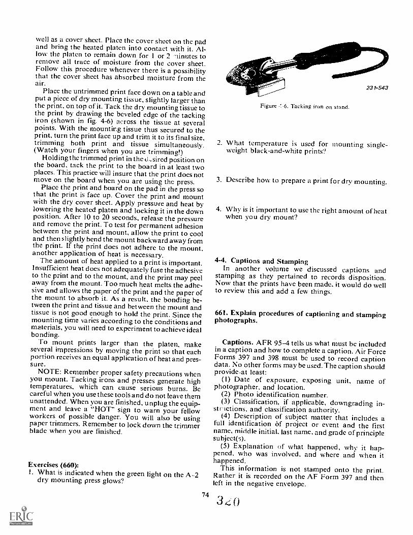
well as a cover sheet. Place the cover sheet on the padand bring the heated platen into contact with it. Al-low the platen to remain down for 1 or 2 linutes toremove all trace of moisture from the cover sheet.Follow this procedure whenever there is a possibilitythat the cover sheet has absorbed moisture from theair.
Place the untrimmed print face down on a table andput a piece of dry mounting tissue, slightly larger thanthe print, on top of it. Tack the dry mounting tissue tothe print by drawing the beveled edge of the tackingiron (shown in fig. 4-6) across the tissue at severalpoints. With the mounting tissue thus secured to theprint, turn the print face up and trim it to its final size,trimming both print and tissue simultaneously.(Watch your fingers when you are trimming!)
Holding the trimmed print in the ki,sired position onthe board, tack the print to the board in at least twoplaces. This practice will insure that the print does notmove on the board when you are using the press.
Place the print and board on the pad in the press sothat the print is face up. Cover the print and mountwith the dry cover sheet. Apply pressure and heat bylowering the heated platen and locking it in the downposition. After 10 to 20 seconds, release the pressurearid remove the print. To test for permanent adhesionbetween the print and mount, allow the print to cooland then slightly bend the mount backward away fromthe print. If the print does not adhere to the mount,another application of heat is necessary.
The amount of heat applied to a print is important.Insufficient heat does not adequately fuse the adhesiveto the print and to the mount, and the print may peelaway from the mount. Too much heat melts the adhe-sive and allows the paper of the print and the paper ofthe mount to absorb it. As a result, the bonding be-tween the print and tissue and between the mount andtissue is not good enough to hold the print. Since themounting time varies according to the conditions andmaterials, you will need to experiment to achieve idealbonding.
To mount prints larger than the platen, makeseveral impressions by moving the print so that eachportion receives an equal application of heat and pres-sure.
NOTE: Remember proper safety precautions whenyou mount. Tacking irons and presses generate hightemperatures, which can cause serious burns. Becareful when you use these tools and do not leave themunattended. When you are finished, unplug the equip-ment and leave a "HOT" sign to warn your fellowworkers of possible danger. You will also be usingpaper trimmers. Remember to lock down the trimmerblade when you are finished.
Exercises (660):1. What is indicated when the green light on the A-2
dry mounting press glows?
74
Figure Tacking iron on stand.
2. What temperature is used for mounting single-weight black-and-white prints?
3. Describe how to prepare a print for dry mounting.
4. Why is it important to use the right amount of heatwhen you dry mount?
4-4. Captions and StampingIn another volume we discussed captions and
stamping as they pertained to records disposition.Now that the prints have been made, it would do wellto review this and add a few things.
661. Explain procedures of captioning and stampingphotographs.
Captions. AFR 954 tells us what must be includedin a caption and how to complete a caption. Air ForceForms 397 and 398 must be used to record captiondata. No other forms may be used. The caption shouldprovide ,at least:
(1) Date of exposure, exposing unit, name ofphotographer, and location.
(2) Photo identification number.(3) Classification, if applicable, downgrading in-
strictions, and classification authority.(4) Description of subject matter that includes a
full identification Of project or ev ent and the firstname, middle initial, last name, and grade of principlesubject(s).
(5) Explanation of what happened, why it hap-pened. who was involved, and where and when ithappened.
This information is not stamped onto the print.Rather it is recorded on the AF Form 397 and thenleft in the negative envelope.
34;,0
Ink Stamping. All ot the photographic prints orrecord material must have certain information at-tached in such a manner that it becomes a permanentpart of the photograph. Thc information, as a mini-mum nuist include:
(I) The original identification number.(2) Classification if applicable.You can make this information a permanent part of
the photo by using friskets and by typing or inkstamping on the back of the prims.
The easiest method is to use an ink-stamping device.The information that you put on the print shouldconform to the following example:
OFFICIAL [S AIR FORCE 1110 1.013(0 Photo Sq (AAVS) (MA(')1-7N-I 369 I'S
Some organizations include the photographer'sname.
The ink-stamping device may be a fairly elaborate,e wet rical, continuous device or, perhaps, only a hand-held stamp. The most important part of stamping isnot the device but rather the ink.
If you are using fiber-base paper. the type of ink isnot terribly important. However,if you need to stampRC paper you must use an air-Awl-based ink. This isbecause regular ink will not dry fast enough nor ad-here to RC paper. It will run and smear, generallymaking a terrible mess.
After you have stamped the prints, stack them backto back or face to face. Never stack them back to facebecause you run the risk of the ink smearing the faceof the print.
Exercises (661):I. Which Air Force regulation governs captioning
photographic materials?
2. What is the easiest method of making written in-formation a permanent part of the photograph?
3. Why must you use fast drying ink to stamp RCpaper?
4-5. Operator MaintenanceBy now you must have guessed that operator main-
tenance is a very important part of your every daytasks and duties. Your finishing equipment is just asimportant as any other photographic equipment.Don't neglect it just because it is in the finishing roomand is not seen by very many people,
662. Specify principles and techniques related tooperator maintenance of finishing equipment.
Once again, as in other areas. cleanliness is the firststep in finishing equipment operator maintenance.Washers, dryers, trimmers, and mounters must bekept clean. You must also check for loose fittings,nuts, bolts, screws. 1.00k for frayed electrical cordsand connect ions.
Washers. Use a elean wet sponge to clean the ex-terior of a washer.
The water tank of the washer should be cleaneddaily. Use soap and scrub the tank vigorously to en-sure that no chemical deposits can be left in the tank.It will also reduce the possibility of calcium depositsbeing left in the water tank. Every week you shouldremove the drum and give it a very thorough clean-ing. A 10 percent solution of sodium nitrate is suitablefor cleaning the drum. Scrub it vigorously also. Do notuse abrasives to clean the stainless steel components.
Dryers. Check belt dryers for obvious dirt, dust.and chemical spills. Clean and polish the drum accord-ing to the TO. Look at a dried print held obliquely tothe light. Lines in the print indicate scratches on thedrum. Pock marks on the print mean you have dirt anddust on the apron, dirtv predrying solutions, or youhave allowed water to drip on the print just before youfed it onto the drum.
RC dryers such as the Pako Tempro 400 need to becleaned inside and out. Clean the entrance rollers.Check for flat spots on the rollers and have them re-placed as necessary. Flat spots are caused by leavingthe cover shut while the dryer is not working. Thisallows the rollers to stay in contact with each other.Wipe the transport rods with a clean damp sponge.
Mounting Press. Check for working parts such asthe handles, indicator lights. hinges, tension adjust-ments, etc. Those things that you can fix or replace. doso. Those you cannot, have maintenance people re-pair.
Clean the heating platen weekly. The best main-tenance here is to prevent mounting tissue fromsticking to the platen by using a cover sheet.
If you must use a cleaning solution, remove the padfirst. While you have the pad out, clean it with a stiffbrush.
General Procedures. In addition to the obviousbenefits of clean equipment, your cleaning habits willgive you at least one more benefit. That is, as you cleanthe equipment, you can look for other malfunctions.Fix those that you can; identify and have fixed thosethat you cannot.
75
Exercises (662):I. How often should you clean the tank of a print
washer?

2. I ines on a mint dried on a drurn dryer indicate 4. !low can you prevent the entrance rollers on thewhat condition of the drum? RC dryer from being worn flat?
3. Dirt and dust on a dryer ;ipron will cause what de- 5. How do you prevent mounting tissue from beingfeet on the print'? stuck to the heating platen'?
3 9
76
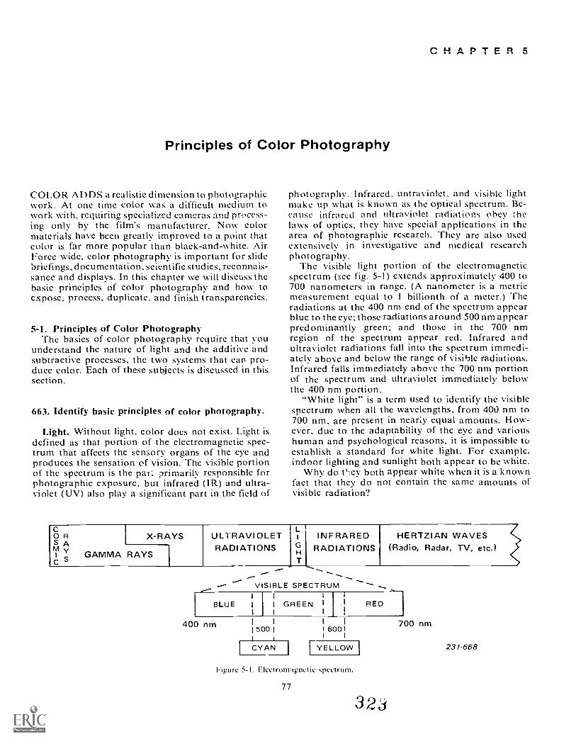
Principles of Color Photography
COLOR ADDS a realistic dimension to photographicwork. At one time color was a difficult medium towork with, requiring specialized cameras and process-ing only by the film's manufacturer. Now colormaterials have been greatly improved to a point thatcolor is far more popular than black-and-white. AirForce wide, color photography is important for slidebriefings, documentation, scientific studies, reconnais-sance and displays. In this chapter we will discuss thebasic principles of color photography and how toexpose, process, duplicate, and finish transparencies.
5-1. Principles of Color PhotographyThe basics of color photography require that you
understand the nature of light and the additive andsubtractive processes, the two systems that can pro-duce color. Each of these subjects is discussed in thissection.
663. Identify basic principles of color photography.
Light. Without light, color does not exist. Light isdefined as that portion of the electromagnetic spec-trum that affects the sensory organs of the eye andproduces the sensation of vision. The visible portionof the spectrum is the pall primarily responsible forphotographic exposure, but infrared (IR) and ultra-violet (UV) also play a significant part in the field of
CHAPTER 5
photography. Infrared, untraviolet, and visible lightmake up what is known as the optical spectrum. Be-cause infrared and ultraviolet radiations obey :helaws of optics, they have special applications in thearea of photographic research. They are also usedextensively in investigative and medical researchphotography.
The visible light portion of the electromagneticspectrum (see fig. 5-1) extends approximately 400 to700 nanometers in range. (A nanometer is a metricmeasurement equal to I billionth of a meter.) Theradiations at the 400 nm end of the spectrum appearblue to the eye; those radiations around 500 nm appearpredominantly green; and those in the 700 nmregion of the spectrum appear red. Infrared andultraviolet radiations fall into the spectrum immedi-ately above and below the range of visible radiations.Infrared falls immediately above the 700 nm portionof the spectrum and ultraviolet immediately belowthe 400 nm portion.
"White light" is a term used to identify the visiblespectrum when all the wavelengths, from 400 nm to700 nm, are present in nearly equal amounts. How-ever, due to the adaptability of the eye and varioushuman and psychological reasons, it is impossible toestablish a standard for white light. For example.indoor lighting and sunlight both appear to be white.
Why do t'ley both appear white when it is a knownfact that they do not contain the same amounts ofvisible radiation?
BX-RAYS ULTRAVIOLET 1 INFRARED HERTZIAN WAVES <
AM y
GAMMA RAYSRADIATIONS G RADIATIONS (Radio, Radar, TV, etc.)
1H
C -- ---- ..... .....-- --..... --.VISIBLE SPECTRUM
r BLUE I
I
,
I
1
GREEN,
I
!
RED
400 nm 1500 I
I CYAN I
6001
[YELLOW
Figure 5-1. Flectrom,ignetie spectrum.
77
323
700 nm
231-668
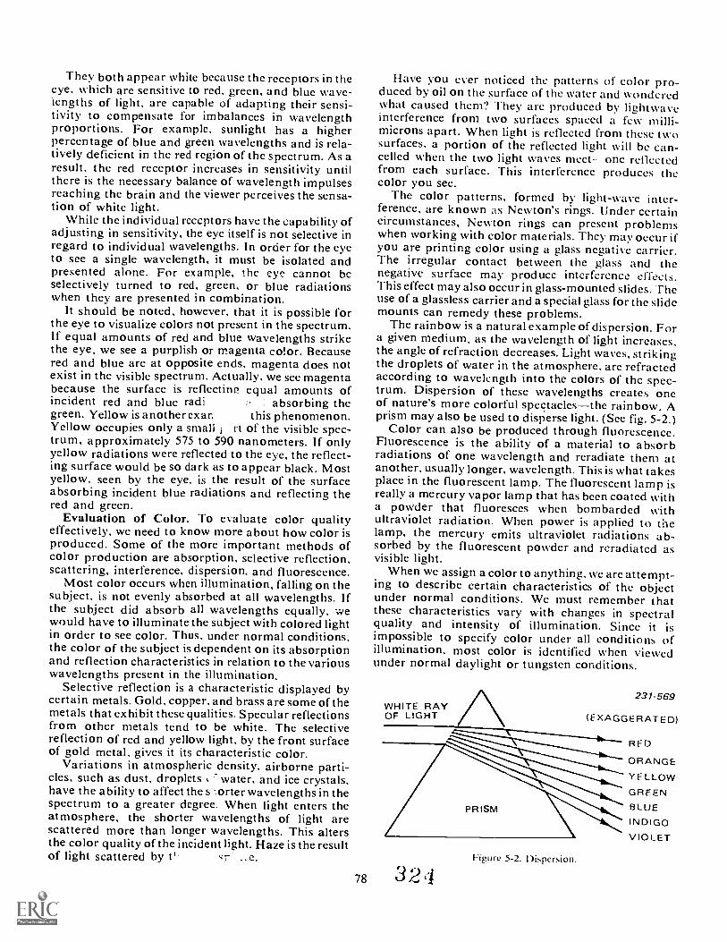
They both appear white because the receptors in theeye, which are sensitive to red, green, and blue wave-lengths of light, are capable of adapting their sensi-tivity to compensate for imbalances in wavelengthproportions. For example, sunlight has a higherpercentage of blue and green wavelengths and is rela-tively deficient in the red region of the spectrum. As aresult, the red receptor increases in sensitivity untilthere is the necessary balance of wavelength impulsesreaching the brain and the viewer perceives the sensa-tion of white light.
While the individual receptors have the capability ofadjusting in sensitivity, the eye itself is not selective inregard to individual wavelengths. In order for the eyeto see a single wavelength, it must be isolated andpresented alone, For example, the eye cannot beselectively turned to red, green, or blue radiationswhen they are presented in combination.
It should be noted, however, that it is possible forthe eye to visualize colors not present in the spectrum.If equal amounts of red and blue wavelengths strikethe eye, we see a purplish or magenta color. Becausered and blue are at opposite ends, magenta does notexist in the visible spectrum. Actually, we see magentabecause the surface is reflectin2 equal amounts ofincident red and blue radi absorbing thegreen. Yellow is another exar, this phenomenon.Yellow occupies only a small rt of the visible spec-trum, approximately 575 to 590 nanometers. If onlyyellow radiations were reflected to the eye, the reflect-ing surface would be so dark as to appear black. Mostyellow, seen by the eye, is the result of the surfaceabsorbing incident blue radiations and reflecting thered and green.
Evaluation of Color. To evaluate color qualityeffectively, we need to know more about how color isproduced. Some of the more important methods ofcolor production are absorption, selective reflection,scattering, interference, dispersion, and fluorescence.
Most color occurs when illumination, falling on thesubject, is not evenly absorbed at all wavelengths. Ifthe subject did absorb all wavelengths equally, wewould have to illuminate the subject with colored lightin order to see color. Thus, under normal conditions,the color of the subject is dependent on its absorptionand reflection characteristics in relation to the variouswavelengths present in the illumination.
Selective reflection is a characteristic displayed bycertain metals. Gold, copper, and brass are some of themetals that exhibit these qualities. Specular reflectionsfrom other metals tend to be white. The selectivereflection of red and yellow light, by the front surfaceof gold metal, gives it its characteristic color.
Variations in atmospheric density, airborne parti-cles, such as dust, droplets water, and ice crystals,have the ability to affect the s -loner wavelengths in thespectrum to a greater degree. When light enters theatmosphere, the shorter wavelengths of light arescattered more than longer wavelengths. This altersthe color quality of the incident light. Haze is the resultof light scattered by t' cr e.
Have you ever noticed the patterns of color pro-duced by oil on the surface of the water and wonderedwhat caused them? They are produced by lightwaveinterference from two surfaces spaced a few milli-microns apart. When light is reflected from these twosurfaces, a portion of the reflected light will be can-celled when the two light waves meetone reflectedfrom each surface. This interference produces thecolor you see.
The color patterns, formed by light-wave inter-ference, are known as Newton's rings. Under certaincircumstances, Newton rings can present problemswhen working with color materials. They may occur ifyou are printing color using a glass negative carrier.The irregular contact between the glass and thenegative surface may produce interference effects.This effect may also occur in glass-mounted slides. Theuse of a glassless carrier and a special glass for the slidemounts can remedy these problems.
The rainbow is a natural example of dispersion. Fora given medium, as the wavelength of light increases,the angle of refraction decreases. Light waves, strikingthe droplets of water in the atmosphere, are refractedaccording to wavelength into the colors of thc spec-trum. Dispersion of these wavelengths creates oneof nature's more colorful spectaclesthe rainbow. Aprism may also be used to disperse light. (See fig. 5-2.)
Color can also be produced through fluorescence.Fluorescence is the ability of a material to absorbradiations of one wavelength and reradiate them atanother, usually longer, wavelength. This is what takesplace in the fluorescent lamp. The fluorescent lamp isreally a mercury vapor lamp that has been coated witha powder that fluoresces when bombarded withultraviolet radiation. When power is applied to thelamp, the mercury emits ultraviolet radiations ab-sorbed by the fluorescent powder and rcradiatcd asvisible light.
When we assign a color to anything, we are attempt-ing to describe certain characteristics of the objectunder normal conditions. We must remember thatthese characteristics vary with changes in spectralquality and intensity of illumination. Since it isimpossible to specify color under all conditions ofillumination, most color is identified when viewedunder normal daylight or tungsten conditions.
WHITE RAYOF LIGHT
231- 569
(EXAGGERATED)
RED
ORANGE
YELLOWGREENBLUEINDIGOVIOLET
78 3 2Figure 5-2. Dispersion.
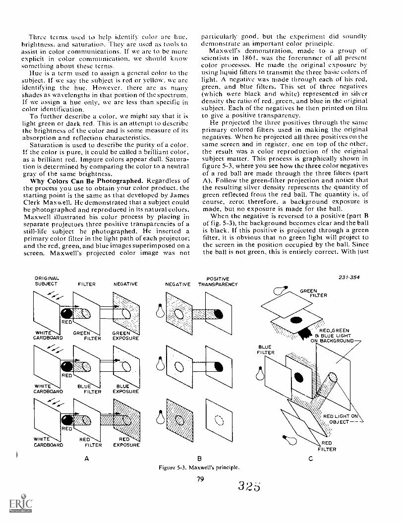
Throe terms used to help identify color arc hue,brightness, and saturation. They are used as tools toassist in color communications. If we are to be moreexplicit in color communication, we should knowsomething about these terms.
Hue is a term used to assign a general color to thesubject. If we sav the subject is red or yellow, we areidentifying the hue. However, there are as manyshades as wavelengths in that portion of the spectrum.If we assign a hue only, we are less than specific incolor identification.
To further describe a color, we might say that it islight green or dark red. This is an attempt to describethe brightness of the color and is some measure of itsabsorption and reflection characteristics.
Saturation is used to describe the purity of a color.If the color is pure, it could be called a brilliant color,as a brilliant red. Impure colors appear dull. Satura-tion is determined by comparing the color to a neutralgray of the same brightness.
Why Colors Can Be Photographed. Regardless ofthe process you use to obtain your color product, thestarting point is the same as that developed by JamesClerk Maxwell. He demonstrated that a subject couldbe photographed and reproduced in its natural colors.Maxwell illustrated his color process by placing inseparate projectors three positive transparencies of astill-life subject he photographed. He inserted aprimary color filter in the light path of each projector;and the red, green, and blue images superimposed on ascreen. Maxwell's projected color image was not
ORIGINALSUBJECT FILTER NEGATIVE
WHITECARDBOARD
GREENFILTER
GREENEXPOSURE
WHITECARDBOARD
BLUEFILTER
BLUEEXPOSURE
ED
WHITECARDBOARD
REDFILTER
A
REDEXPOSURE
particularly good. but the experiment did soundlydemonstrate an important color principle.
Maxwell's demonstration, made to a group ofscientists in 1861, was the forerunner of all presentcolor processes. He made the original exposure byusing liquid filters to transmit the three basic colors oflight. A negative was made through each of his red,green, and blue filters. This set of three negatives(which were black and white) represented in silverdensity the ratio of red, green, and blue in the originalsubject. Each of the negatives he then printed on filmto give a positive transparency.
He projected the three positives through the sameprimary colored filters used in making the originalnegatives. When he projected all three positives on thesame screen and in register, one on top of the other,the result was a color reproduction of the originalsubject matter. This process is graphically shown infigure 5-3, where you see how the three color negativesof a red ball are made through the three filters (partA). Follow the green-filter projection and notice thatthe resulting silver density represents the quantity ofgreen reflected from the red bail. The quantity is, ofcourse, zero; therefore, a background exposure ismade, but no exposure is made for the ball.
When the negative is reversed to a positive (part Bof fig. 5-3), the background becomes clear and the ballis black. If this positive is projected through a greenfilter, it is obvious that no green light will project tothe screen in the position occupied by the ball. Sincethe ball is not green, this is entirely correct. With just
POSITIVENEGATIVE TRANSPARENCY
Figure 5-3. Maxwell's principle.
79
GREENFILTER
231-354
RED ,G RE EN8, BLUE LIGHT
ON BACKGROUNDBLUE
Fl LTER
3 2 6
RED LIGHT ONOBJECT
REDFl LTER
the green filter positive, the projection is a greenbackground with a black hall. Using all three positives(part C of fig. 5-3). the background projects white.which is the sum of all three primary colors. The ballimage projects red, because only red light is allowed tofall on the area of the screen.
One outstanding deficiency is immediately apparentwhen considering Maxwell's demonstration, and thaiis its lack of permanence. A color picture could beprojected on a screen, but that was all. This was not aphotograph that could be mounted in a picture frameor placed in an album. Commercial use of Maxwell'sdiscoveries had to wait for a manufacturing processthat could use their possibilities.
Exercise (663):1. State basic principles of color photography by
completing the following statements:a. Without color does not exist.
b. The optical spectrum is made up oflight, plus and
c. Visible light runs from tonanometers.
d. Due to eyc both indoor and day-light illumination may appear white.
e. Equal amounts of blue and red light produce
f. The color of an object is determined by itsand characteristics.
g. Selective reflection is a characteristic displayedby
h. Newton rings are caused by
i. The rainbow is caused by
material absorbs radiation atoi wavelength and re-radiates it at another.
k. Impure color lacks
I. Maxwell's demonstration used the threecolors.
664. Specify principles of the additive process ofcolor photography.
The Additive Color Process. Exposure of color film.and to a more limited degree color printing paper,applies the principles of the additive color process.The additive process, applying the principles devel-oped by Maxwell, uses the primary colors of blue,green, and red.
When equal parts of blue, green, and red light areprojected from separate projectors and are partiallysuperimposed on a screen, you see in the area of over-lap of all three colors, white, as shown in figure 5-4.The area of overlap between the blue and green lightproduces cyan (blue green), the area of overlap of thered and blue light produces magenta, and the overlapof the red and green light produces yellow. Almostany desired color match can be produced by varyingthe amount of one of the two colors used for producingthat color. For example. if you have equal proportionsof red and green, the result is yellow; by increasing theamount of red, the result is orange. Since matching awide range of colors with red, green, and blue lightinvolves addition of the colored light, the primarycolors are often identified further as the additiveprimaries.
In color photography, the three colors produced bymixtures of additive primaries in pairs are of particularimportance. These colorscyan, magenta, andyelloware known as the subtractive primaries. Sinceeach represents white light minus one of the additiveprimaries, the subtractive primaries are the comple-ments of the additive primaries. For example, cyanand red light blend together to give white light. Similar-ly, magenta is complementary to green, and yellow is.complementary to blue.
At this point, refer to figure 5-5 and study theillustration of the color star. Remember which colorsare the additive primaries (blue, green, and red) andnotice that the subtractive primary colors between anytwo of the additive primaries are mixtures of these twoprimary colors. Also, notice the colors that are directlyopposite to each other in this star; these colors arecomplementary to each other.
80 3 2 6.

Figure 5-4. Additive color system.
Although the original photographic record on color b. A combination of equal amounts of red andfilm uses the additive primary colors, these are not green light producessuitable for the final color product. This is because anycombination of primary colors over one light sourceresults in neutral density. A transparency, for example,must be viewable when you use only one white lightsource. It is the subtractive process, discussed in the c. The subtractive primaries arenext objective, that makes the "final product" possible. and
Exercise (664):1. Complete the following statements regarding the
additive process.a. The additive color process requires
separate light sources.
81
d. Yellow is the complement of
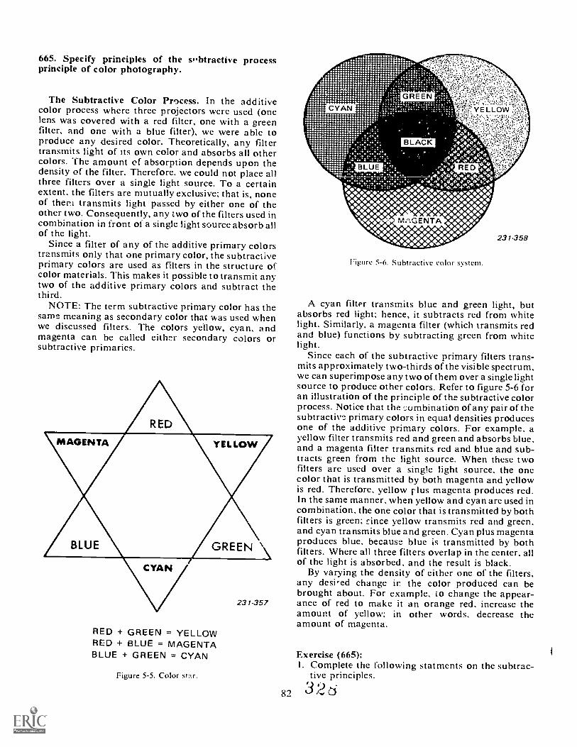
665. Specify principles of the sbtractive processprinciple of color photography.
The Subtractive Color Pr9cess. In the additivecolor process where three projectors were used (onelens was covered with a red filter, one with a greenfilter, and one with a blue filter), we were able toproduce any desired color. Theoretically, any filtertransmits light of its own color and absorbs all othercolors. The amount of absorption depends upon thedensity of the filter. Therefore, we could not place allthree filters over a single light source. To a certainextent, the filters are mutually exclusive; that is, noneof them transmits light passed by either one of theother two. Consequently, any two of the filters used incombination in front of a single light source absorb allof the light.
Since a filter of any of the additive primary colorstransmits only that one primary color, the subtractiveprimary colors are used as filters in the structure ofcolor materials. This makes it possible to transmit anytwo of the additive primary colors and subtract thethird.
NOTE: The term subtractive primary color has thesame meaning as secondary color that was used whenwe discussed filters. The colors yellow, cyan, andmagenta can be called either secondary colors orsubtractive primaries.
RED + GREEN = YELLOWRED + BLUE = MAGENTABLUE + GREEN = CYAN
Figure 5-5. Color star.
Figure 5-6. Subtractive color system.
A cyan filter transmits blue and grecn light, butabsorbs red light; hence, it subtracts red from whitelight. Similarly, a magenta filter (which transmits redand blue) functions by subtracting green from whitelight.
Since each of the subtractive primary filters trans-mits approximately two-thirds of the visible spectrum,we can superimpose any two of them over a single lightsource to produce other colors. Refer to figure 5-6 foran illustration of the principle of the subtractive colorprocess. Notice that the ..:ombination of any pair of thesubtractive primary colors in equal densities producesone of the additive primary colors. For example, ayellow filter transmits red and green and absorbs blue,and a magenta filter transmits red and blue and sub-tracts green from the light source. When these twofilters are used over a single light source, the onecolor that is transmitted by both magenta and yellowis red. Therefore, yellow plus magenta produces red.In the same manner, when yellow and cyan are used incombination, the one color that is transmitted by bothfilters is green; since yellow transmits red and green,and cyan transmits blue and green. Cyan plus magentaproduces blue, because blue is transmitted by bothfilters. Where all three filters overlap in the center, allof the light is absorbed, and the result is black.
By varying the density of either one of the filters,any desi-ed change ir the color produced can bebrought about. For example, to change the appear-ance of red to make it an orange red, increase theamount of yellow; in other words, decrease theamount of magenta.
Exercise (665):I. Complete the following statments on the subtrac-
tive principles.Q .
8'7 E2$
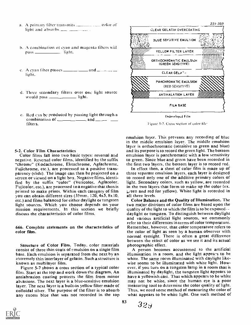
a. ,N primary filter transmits CORIt oflight and absorbs
b. A combination of cyan and magenta filters witlpass _
c. A cyan filter passes andlight.
d. Three secondary filters over onc light sourceWould pass light.
e. Red c:m be produced by passing light through acombination of andfilters.
5-2. Color Film Chat acteristicsColor films fall into two basic types: reversal and
negative. Reversal color films, identified by the suffix"chrome" (Kodachrome, Ektachrome, Agfachrome,Fujichrome, etc.), are processed to a positive trans-parency (slide). The image can then be projected on ascreen or viewed on a light box. Negative films, identi-fied by the suffix "color" (Vericolor, Agfacolor,Fujicolor, etc.), are processed to a negative that then isprinted to make prints. Within each category of filmyou can obtain different sizes (35mm, 120, 4x5, 8x 10,etc.) and films balanced for either daylight or tungstenlight sources. Which you choose depends on yourmission requirements. In this section we brieflydiscuss the characteristics of color films.
666. Complete statements on the characteristics ofcolor film.
Structure of Color Film. Today, color materialsconsist of three thin coats of emulsion on a single filmbase. Each emulsion is separated from the next by anextremely thin interlayer of gelatin. Such a structure isknown as multilayer film.
Figure 5-7 shows a cross section of a typical colorfilm. Start at the top and work down the diagram. Anantiabrasion coating protects the film from minorabeasions. The next layer is a blue-sensitive emulsionlayer. The next layer is a built-in yellow filter made ofcolloidal silver. The purpose of the filter is to absorbany excess blue that was not recorded in the top
CLEAR GELATIN OVERCOATING
231-359
\\V YELLOW FILTER LAYER
ORTHOCHROMATIC EMULSION(GREEN SENSMVE)
PANCHROMATIC EMULSION
(RED SENSITIVE)
Unde%ekped Film
igure 5-7. Cross section of color l
emulsion layer. This prevents any recording of bluein the middle emulsion layer. The middle emulsionlayer is orthochromatic (sensitive to green and blue)and its purpose is to record the green light. The bottomemulsion layer is panchromatic with a low sensitivityto green. Since blue and green have been recorded inthe first two layers, the bottom layer is to record red.
In effect then, a sheet of color film is made up ofthree separate emulsion layers, each layer is designedto record only one of the additive primary colors oflight. Secondary colors, such as yellow, are recordedin the two layers that form to make up the color (ex.L,eeen and red for yellow). White light is recorded inall three levels.
Color Balance and the Quality of Illumination. Thetwo major divisions of color films are based upon thequality of the light to which the film is to be exposeddaylight or tungsten. To distinguish between daylightand various artificial light sources, we commonlyrefer to their differences in terms of color temperature.Remember, however, that color temperature refers tothe color of light as seen by a human observer withnormal eyesight. There is often a great differencebetween the etfect of color as we see it and its actualphotographic effect.
A person becomes accustomed to the artificialillumination in a room, and the light appea-s to bewhite. The same room illuminated with daylight like-wise seems to be illuminated with white light. How-ever, if you turn on a tungsten lamp in a room that isilluminated by daylight, the tungsten light appears tohave a yellowish cast. That which appears to be whitemay not be white, since the human eye is a poormeasuring tool to determine the color quality of light.Thus, we need some method of measuring the color ofwhat appears to be white light. One such method of
83

measurement is the color temperature scale. expressedas degrees Kelvin the temperature to which a blackbody radiator mast be hcated in order to emit lightequal to a source such as tungsten lamps, the sun, etc.The scale starts at ---.273° Celsius (absolute zero),which is designated as zero Kelvin. The scale hasbecome universal in the measurement of colortem perature.
All tungsten or daylight sources are not at the samecolor temperature. Table 5-1 lists the commonly usedlight sources and their approximate color temperatures.
From your experience with the film characteristicsof black-and-white film, you probably recall that theeffective film speed often changed when you switchedfrom daylight to tungsten light. The reason for thischange was the difference in the spectral quality or thecolor content of the light. A change in filrn speed inblack-and-white film usually compensates for aradical change in light quality, but this is not the casewith color film; herc you must consider color tempera-ture. Color film is in correct balance for only onc typeof light and should be used undcr specific light con-ditions. If thcse conditions change, then the colorsyou photograph appear degraded or out of balance.Normally, each manufacturer makes at least two typesof color filmone to be used under tungsten light andthe other to be used under daylight conditions.
A knowledge of color temperature is valuable toyou; however, the Kelvin rating of a light sourcc is notthe only factor to consider. For example, two lightsources, a tungsten and a fluorescent, may be rated ashaving the samc color temperature, but their effectupon color film may vary considerably because ofdifferences in their spectral distribution qualities. Forthe same basic reason, the selection of a filter forproper balance cannot always be predicted on thebasis of its effect upon color temperature alone, as youwill discover by following the manufacturer's recom-mendations and by making tests of your own.
Daylight Film. Daylight color film is balanced at5400 K. This means that because of the high bluecontent of a light with this color temperature, the filmis made with a relatively lower sensitivity in the bluerecord emulsion and with a higher sensitivity in the redrecord emulsion. Consequently, the excessive blue isminimized, and all reds are strengthcned in the finaltransparency. As a consequence the film must bcexposed to predominantly blue light sources likedaylight or electronic flash.
When daylight film is exposed to light with a pre-ponderance of red, like tungsten lighting, this excessred degrades all colors, and the transparency takes ona reddish cast. Essentially the same effect is obtainedby exposing daylight film just after sunrise or justbefore sunset. You have probably noticed the pre-dominantly red light at these times even though theeye is a poor judge of color. The opposite, or a bluishcast, commonly appears in various winter snow scenes.As a matter of fact, the shadow are definitely blue inany outdoor picture, because they are illuminated bysky rather than by sunlight. Skylight is largely blue
84
TABLV 5-1AppRom \ I CO I ) \IN R \ I ( RI01 (O\INIO\I Y 1'1) I Rd( I SO[1:(.1
231-696
LIGHT SOURCE DEGREES KELVIN
Tungsten House Lamps 2670 - 2810
Lamps for Color Photography 3200
Photoflood Lamps 3400
White Fluorescent Lamps 3500
Clear Flash lamps 3800
Photoflash "228" or "58" 5400
Daylight (Standard), 5400
Average 10 A.M. to 3 P.M. Sunlight 6000 - 6200
Daylight Fluorescent Lamps 6500
Electronic Flashtubes 5800 - 7000
Overcast Sky 6800
Clear Blue Sky 12.000 and up
because the short wavelengths of blue light are easilyscattered by atmospheric dust and haze. 1 nis, then, isthe light that illuminates shadow areas.
Off-color transparencies and prints are not neces-sarik poor. Take a look at thc color illustrations inany photographic magazine. Many top photographersdeliberately use light of the wrong color temperatureto shoot pictures. A reddkh cast produces a warmtonc, while an excess of blue is cold. Of course, theseare special effects designed to crcate a particularmood.
Tungsten Film. As might be expected, film manu-facturers also produce color materials that are de-signed for use under tungsten illumination. Theseemulsions are specifically color balanced for illumina-tion that measures cither 3200 K (tungsten). Tungstenlighting is rich in red; therefore, thc tungsten type ofcolor films are made with a pronounced sensitivity toblue in order to compensate for the lac}, of blue inthis kind of illumination. This is the reason why, whenyou examine a roll of tungsten transparency filmexposed in daylight, the colors appear to have anoverall bluish cast. By using the appropriate conver-sion filter, you can use tungsten film in daylight andget satisfactory results.
It is important to determine the exact tungstenrating of the illumination so that you can choose theappropriate filters that may be necessary. You alsoshould know that the color temperature of a lightingsource can change with time and with line voltagefluctuations. For example, many tungsten bulbsdesigned for photographic use are only guaranteedto put out a particular temperature for a couple of
3
hours, In addition, a line voltage change of I volt willchange the color temperature by 10 K in the directionof the change. Therefore a 10-volt increase wouldincrease color temperature by 100.
NOTE: While not covered in this CDC, there arecolor temperature meters for measuring the colortemperature of any light source. This type of meter isinvaluable in color photography.
Exercise (666):1. Complete statements on the characteristics of color
film.a. Color films have emulsion layers.
The middle emulsion in color film is designedto record light.
c. A colloidal silver layer is foundbetween t he andemulsion layers of color film.
d. The bottom emulsion layer of color film is atype film that is designed to
record light.
e. Cyan would be recorded in the a ndemulsion layers.
f. Tungsten household lamps would be richer inlight than tungsten lamps designed
for color photography.
g. Daylight is rich in
h. Daylight color film exposed under tungstenlight would give the images a heavycast.
Tungsten film is designed for light sources thatare rich in light.
If the line voltage on a 3200 K lamp went up 20volts, the Kelvin temperature would change to
667. State the procedures for the care and storage ofcolor film.
Care of Color Materials. Much of our discussionabout the care, storage, and handling of black-and-white materials applies equally well to color materials.As you probably know from your experience in buyingcolor film, the cost of color materials and processingis almost three times the cost of using black-and-whitefilms. You can therefore appreciate that thc Air Forcehas a substantial overall investment in color materials.
It is extremely important that any changes in eistiorthe length, width, or thickness of color materials beavcided because of their multilayer structure. As arule by maintaining control over the relative humidity(RH) content and temperature of a properly con-strucved film storage area, you can protect c)lormaterials from environments that cause these changes.As is the case with black-and-white films, keep therelative humidity of the storage facility at 40 to 50percent. This is particularly important with materialswhich have been exposed or processed, for dyechanges will result because of high humidity.
Color materials require low temperatures, as well ascontroll'A humidity conditions, in order to preservethe initial film speed and to maintain color balance.To assure high quality, sealed containers of most kindsof color film can be stored safely for a period ofseveral months at a temperature of 550 F (13° C) orless. For periods longer than 6 months, it is customaryto store color materials at 0° to -10° F ( 18° to 23° C).
NOTE: For good results it is necessary to allow thematerial to warm up to working temperatures priorto use.
In addition to heat and humidity, color materialsshould be guarded against contamination of all kinds.Eim and other materials should never be stored nearchemicals or any other source of vapors. Such vaporscan have permanent effect on the color quality of yourmaterials.
85
Exercises (667):1. Color film should oe stored in an environmen
which has what range of relative humidity?
3 3
2. What should be the temperature for long-termstorage of color film?
3. What is likel to happen to film that is not properlystored?
4. Should color film be stored near photo chemicals?Why?
5-3. Expose Color FilmIn contrast with the problems inherent in earlier
color processes, present-day color films are highlystandardized and effective. Even so, you must controlyour product if you are to obtain consistently goodresults under varying conditions. In this section wewill cover a few points that you should remember inexposing color films.
668. State the principles and techniques of exposingreversal color film.
Exposing Reversal Color rilm. Unlike panchro-matic black-and-white films, color emulsions accu-rately reproduce a much narrower range of brightnessvalues. Normally a scene's contrast cannot be greaterthan 3:1 to hold both the shadows and highlights. Thiscalls upon the photographer to use supplementarylighting for both indoor and outdoor work to keepcontrast low. This is particularly true with reversalfilms. The reversal process uses up all of the sensitivesilver halides in order to obtain the final positiveimage. There is little room for error and exposuresmust normally be within one-half f stop of perfect inorder to guarantee top quality results.
NOTE: Prove this to yourself by picking a typicaloutdoor scene and making an exposure test with thecolor reversal film that you are using. Bracket yourexposures from three under through three over in half-stop increments. Such a test will give you a good ideaof the latitude of the film you are using.
Figure 5-8 illustrates, in a general way, the influencethat narrow film latitude has on the reproduction of ascene when you are using reversal film. For purposesof simplicity, consider each pair of the three views byits respective letter as cross sections of color film. Ineach case, the upper cross section represents the resultsof the film's initial exposure and its first development.Imagine that the original subject was illuminated by apredominantly red light such as you would find in avivid sunset. Consider the shadows, halftones, as wellas highlights, as different densities of the same color.
86
Normally, color material can record . re shades ofbrightness values than figure 5-8 shows. The lowercross section represents the film after it has beenthrough the color developer. In each view, the exposedsilver halides are shown in black, whereas portions ofthe emulsions that remain blank are not affected bylight.
With a normal exposure, about one-half of thesilver halides are affected (see A of fig. 5-8). Note thatthe film reproduction of the subject would record thesame range of brightness values as the original scene.Compare t he scene results of the normal exposure withthose ot overexposure and underexposure. Theformer, shown in B. would appear as a very thin trans-parency, since the initial overexposure has affectedthe major portion of the silver halides. A considerablysmaller amount of halides remains to be affected byreexposure in the reversal bath and color develop-ment. The highlights appear washed out, as little dyeis produced. Underexposure, as shown in C. affectsless than one-half of the silver halides in the coloremulsion. Therefore, when the reversal process formsthe positive image, the greater part of the silver halidesis affected by reexposure and color development. Thisresults in a much denser positive image which is moresatisfactory than an overexposed image.
NOTE: Your understanding of this will increasewhen we cover processing of reversal film. For nowjust try to get the idea that as you increase exposureover normal the final transparency will be lacking incolor. Conversely, as you decrease exposure, thetransparency will become darker and darker.
Exercises (668):I. VII;at is the exposure latitude of reversal color film?
2. A scene's contrast should not exceed what ratiowhen using reversal film?
3. What is one way you can reduce a scene's contrast?
4. Heavy dye densities result from what type ofreversal exposures?
5-4. Filters for Color PhotographyColor film, unlike the eye, is designed to record light
of a specific Kelvin temperature: 5400 K for daylightfilms and 3200 K for tungsten films. Filters are there- I
fore necessary to filter the available light to match thefilm. There are four categories of filters that perform
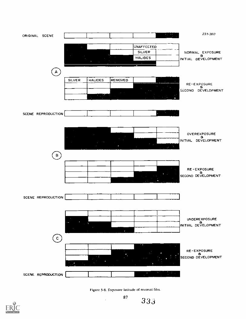
ORIGINAL SCENE
SCENE REPRODUCTION
SCENE REPRODUCTION
SCENE REPRODUCTION
231-360
NORMAL EXPOSUREa
INITIAL DEVELOPMENT
RE-EXPOSUREa
SECOND DEVELOPMENT
OVEREXPOSUREa
INITIAL DEVELOPMENT
1!1=1MIi=
Figure 5-8. Exposure latitude of reversal film.
873 3
RE -EXPOSUREa
SECOND DEVELOPMENT
UNDEREXPOSUREa
INITIAL DEVELOPMENT
RE-EXPOSUREa
SECOND DEVELOPMENT
this task: ( I) conversion filters, (2) light-balancing(correction) filters, (3) color compensating filters, and(4) special purpose filters. Filters for color photo-graphy are less dense than those used for black-and-white photography, hut their principles of applicationarc the same.
669. Choose the correct filter to be used under differentphotographic situations involving color film.
Conversion Filters. Cons ersion filters are verystrong filters and are used for exposing tungsten-typecolor films under daylight conditions and daylightfilm under tungsten illumination. The following listindicates the filter to use:
StopFilm Type Lighting Filter 1 ncreaseDaylight 3200 K. Lamps 80ADaylight 3400 K Lamps 8013 2 2 3
(Photofloods)Daylight Clear Flash 80C'
(3800 K)-type 13(Balanced for3200 K) Daylight 8513 2 3
NOTE: Type 80 filters are blue in color, whereas 85'sare yellowish. This and other lists in this section arejust guides. You must follow the recommendationsof the film's manufacturer.
Light Balancing Filters. Light balancing filters arepaler than conversion filters. They are used for slightadjustments within the general light balance of the film(i.e., match .ag type B film to different types of tungstenlighting, etc.). The following is a list of commonly usedlight balancing filters:
12 StopFilm Type Filter Purpose IncreaseDaylight 8IA Absorbs excess blue in cloudy I 3
weather. shade or when usingelectronic flash indoors.
Type 13 81A When using type 13 film with I 3photofloods.
Daylight 8IB Same application as an 81A but 1 3with stronger results.
Daylight 82A Reduces the excessive warmth I 3found in early morning and lateafternoon light.
NOTE: 81 filters are yellowish, wherc-s an 82 is abluish filter.
Color-Compensating Filters. Color-compensatingfilters come in pale tints of red, green, blue, magenta,
yellow, and 'van. 1 hey are tisod to make very subtlecolor changes. A very large selection of densities arcavailable, as shown in table 5-2. For this reason color-compensating filters are available in gelatin sheets.
Special Filters, Special filters have been designedfor specific light-balancing problems. The followinglist shows a few filters that are available,
I1.51_ 1.`r Pl 111.1 FR
Daylight 1.1.D
Type 13 1:1.13
Daylight C30R
1- STOPPt' R POSE INCRUASt.Fliminates the blne-gi.cncast which results whenshooting daylight tihnunder nuoresecro
1 sed when shooting typefilrn limier fluorescent I
whcn using daylight hlm 2underwater.
Exercise (669):I. Which filter would you choose for each of the
following situations?a. Shooting daylight film with tungsten lighting.
h. Using type B film with photofloods.
c. Shootina type B film under fluorescent lights.
d. Using daylight film underwater.
e. When shooting daylight film indoors withelectronic flash.
f. Shooting daylight film with clear flash.
g. Shooting daylight film in the early morning.
5-5. Duplicating TransparenciesIn the Air Force there is an ever-increasing need for
color slides for audiovisual presentations. Slides areused in presentations for briefings, newcomer'sorientations, and especially in training programs.Any subject that can be photographed or copied canbe made into a color slide. Duplicating color slides is
88 3 3

ABLE 5-2TYPICAL COLOR-COM PFNSATING RV) IlL ITRS
FilterNomenclature
Color ColorDensity
Exposure Increasein Stops
CC 025 R 0.025CC 05 R 0.05 1/3CC 10 R Red 0.10 1/3CC 20 R 0.20 1/3
CC 021 G 0.25CC 05 G 0.05 1/3CC 10 G Green 0.10 1/3CC 20 G 0.20 2/3
CC 025 B 0.025CC 05 B 0.05 1/3CC 10 B Blue 0.10 1/3CC 20 B 0.20 2/3
CC 025 Y 0.025CC 05 Y 0.05CC 10 Y Yellow 0.10 1/3CC 20 Y 0.20 1/3
CC 025 C 0.025CC 05 C 0.05 1/3CC 10 C Cyan 0.10 1/3CC 20 C 0.20 1/3
CC 025 M 0.025CC 05 M 0.05 1/3CC 10 M Magenta 0.10 1/3CC 20 M 0.20 1/3
Note: * All the above filters are also available in additional densities of .30, .40, and 50. If filtersare used in combination, exposure increase should be obtained by trial and error. 231-697
the main duplication task of many photo labs. Thereare many different type:, of slide duplication camerasused throughout th:.; Air Force and they range fromsimple to very con- plex. A common one that is widelyused is the Reprenar Model 805 slide duplicatingcamera.
670. Using figures 5-9 and 5..10, identify the basicfeatures of the Repronar 805 slide duplicating camera.
Equipment Requirements. Regardless of the equip-ment that you use to duplicate transparencies, it mustmeet some basic requirements. You need a 35mmsingle-lens, reflex camera capable of 1:1 reproduction.The light source for making the exposure must bebehind the slide, and a piece of diffusion glass must beused between the slide and the light source to diffuseand even out the light. The commercial duplicatingequipment available for slide duplicating have refine-ments of and additions to these basic requirements.
Repronar 805. The Repronar 805 (figs. 5-9 and5-10) is a special-purpose copy apparatus specificallydesigned for duplicating transparencies. It is a fullyself contained unit complete with the camera, copy
89
stage, and viewing and exposing light sources. It iscapable of making same size, enlargements, andreductions of transparency images.
The camera is a 35mm single-lens reflex equippedwith a long, flexible bellows and an f/ 4 flat field, copylens. The camera is situated on vertical rails above thecopy stage. This configuration is very similar to aprojection printer and permits magnification, reduc-tion, and critical focusing of the transparency image.The camera is capable of 4X magnification and 50percent reduction. The reduction can be used to reduce21/4 X 21/4 (6X6cm) slides to 35mm size.
An exposure compensation calculator indicates thechange in exposure required when making magnifica-tions. It is set by dialing in the film value number of thefilm that you are using. This film value number is notthe same as the film ASA rating. It is a number as-signed to the film by the manufacturer of the Repro-nar. You can find the film value number for differentfilms in the instruction manual for the Repronar.
The exposing light source is electronic flash and issituated belov, the copy stage. It has a high/low powerswitch for controlling exposure. There is also a filterdrawer directly beneath the copy stage. Differentfilters ci be inserted to alter color balance or createspecial et fects.
3 3 6
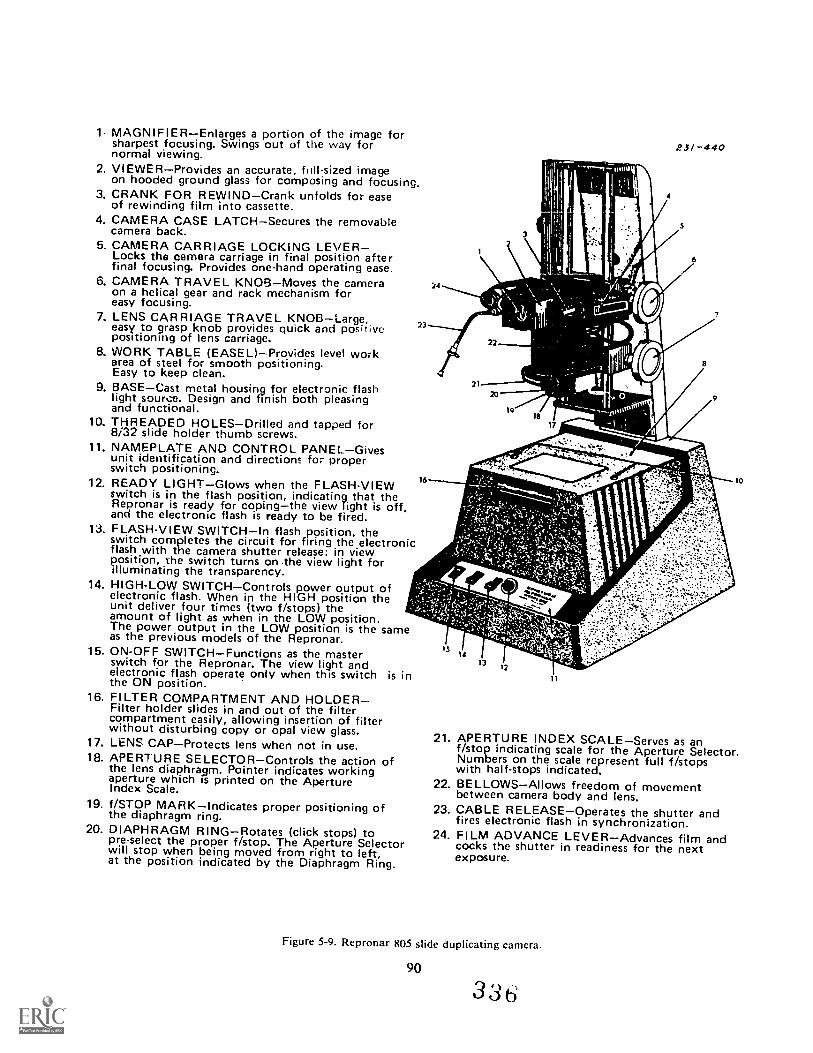
1- MAGNIFIEREnlarges a portion of the image forsharpest focusing. Swings out of the way fornormal viewing.
2. V1EWERProvides an accurate, ftill-sized imageon hooded ground glass for composing and focusing.
3. CRANK FOR REWINDCrank unfolds for easeof rewinding film into cassette.
4. CAMERA CASE LATCHSecures the removablecamera back.
5. CAMERA CARRIAGE LOCKING LEVERLocks the camera carriage in final position afterfinal focusing. Provides one-hand operating ease.
6. CAMERA TRAVEL KNOBMoves the cameraon a helical gear and rack mechanism foreasy focusing.
7. LENS CARRIAGE TRAVEL KNOBLarge,easy to grasp knob provides quick and positivepositioning of lens carriage.
8. WORK TABLE (EASEL)Provides level workarea of steel for smooth positioning.Easy to keep clean.
9. BASECast metal housing for electronic flashlight source. Design and finish both pleasingand functional.
10. THREADED HOLESDrilled and tapped for8/32 sfide holder thumb screws.
11. NAMEPLATE AND CONTROL PANELGivesunit identification and directions for properswitch positioning.
12. READY LIGHTGlows when the FLASH-VIEWswitch is in the flash position, indicating that theRepronar is ready for copingthe view fight is off,and the electronic flash is ready to be fired.
13. FLASH-VIEW SWITCHIn flash position, theswitch completes the circuit for firing the electronicflash with the camera shutter release; in viewposition, the switch turns on.the view light forilluminating the transparency.
14. HIGH-LOW SWITCHControls power output ofelectronic flash. When in the HIGH position theunit deliver four times (two f/stops) theamount of light as when in the LOW position.The power output in the LOW position is the sameas the previous models of the Repronar.
15. ON-OFF SW1TCHFunctions as the masterswitch for the Repronar. The view light andelectronic flash operate only when this switch is inthe ON position.
16. FILTER COMPARTMENT AND HOLDERFilter holder slides in and out of the filtercompartment easily, allowing insertion of filterwithout disturbing copy or opal view glass.
17. LENS CAPProtects lens when not in use.18. APERTURE SELECTORControls the action of
the lens diaphragm. Pointer indicates workingaperture which is printed on the ApertureIndex Scale.
19. f/STOP MARKIndicates proper positioning ofthe diaphragm ring.
20. DIAPHRAGM RINGRotates (click stops) topre-select the proper f/stop. The Aperture Selectorwill stop when being moved from right to left,at the position indicated by the Diaphragm Ring.
B3/-440
11
21. APERTURE INDEX SCALEServes as anf/stop indicating scale for the Aperture Selector.Numbers on the scale represent full f/stopswith half-stops indicated.
22. BELLOWSAllows freedom of movementbetween camera body and lens.
23. CABLE RELEASEOperates the shutter andfires electronic flash in synchronization.24. FILM ADVANCE LEVERAdvances film andcocks the shutter in readiness for the next
exposure.
Figure 5-9. Repronar 805 slide duplicating camera.
90
3 3
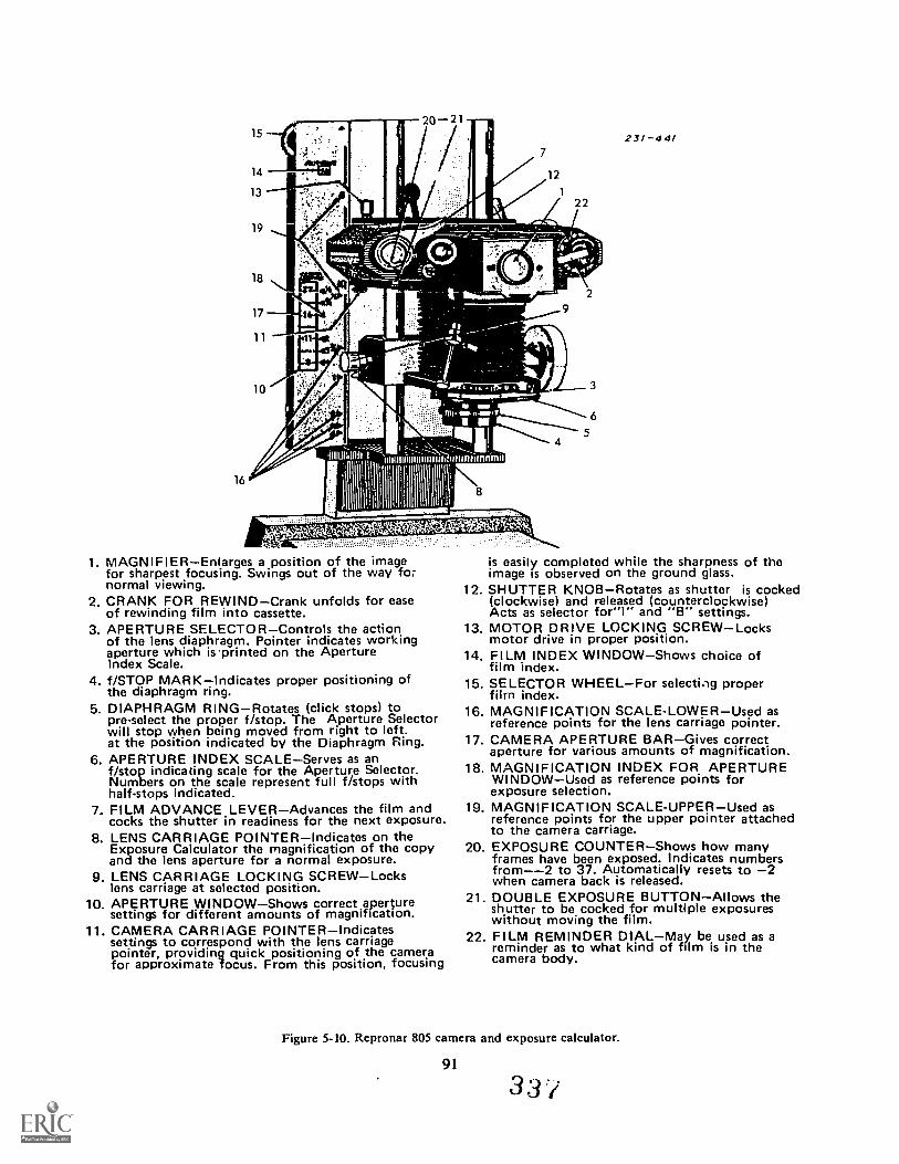
ITIIsn-woor
11111111 - =on III NI Inumnsminiunnmui'11',
9
341
1. MAGNIFIEREnlarges a position of the imagefor sharpest focusing. Swings out of the way fornormal viewing.
2. CRANK FOR REWINDCrank unfolds for easeof rewinding film into cassette.
3. APERTURE SELECTORControls the actionof the lens diaphragm. Pointer indicates workingaperture which is-printed on the ApertureIndex Scale.
4. f/STOP MARKIndicates proper positioning ofthe diaphragm ring.
5. DIAPHRAGM RINGRotates (click stops) topre-select the proper f/stop. The Aperture Selectorwill stop when being moved from right to left.at the position indicated by the Diaphragm Ring.
6. APERTURE INDEX SCALEServes as anf/stop indicating scale for the Aperture Selector.Numbers on the scale represent full f/stops withhalf-stops indicated.
7. FILM ADVANCE LEVERAdvances the film andcocks the shutter in readiness for the next exposure.
8. LENS CARRIAGE POINTERIndicates on theExposure Calculator the magnification of the copyand the lens aperture for a normal exposure.
9. LENS CARRIAGE LOCKING SCREWLockslens carriage at selected position.
10. APERTURE WINDOWShows correct aperturesettings for different amounts of magnification.
11. CAMERA CARRIAGE POINTERIndicatessettings to correspond with the lens carriagepointer, providing quick positioning of .the camerafor approximate focus. From this position, focusing
2
3
6
5
231-441
is easily completed while the sharpness of theimage is observed on the ground glass.
12. SHUTTER KNOBRotates as shutter is cocked(clockwise) and released (counterclockwise)Acts as selector for"I" and "B" settings.
13. MOTOR DRIVE LOCKING SCREWLocksmotor drive in proper position.
14. FILM INDEX WINDOWShows choice offilm index.
15. SELECTOR WHEELFor selectiAg properfilm index.
16. MAGNIFICATION SCALE-LOWERUsed asreference points for the lens carriage pointer.
17. CAMERA APERTURE BARGives correctaperture for various amounts of magnification.
18. MAGNIFICATION INDEX FOR APERTUREWINDOWUsed as reference points forexposure selection.
19. MAGNIFICATION SCALE-UPPERUsed asreference points for the upper pointer attachedto the camera carriage.
20. EXPOSURE COUNTERShows how manyframes have been exposed. Indicates numbersfrom--2 to 37. Automatically resets to 2when camera back is released.
21. DOUBLE EXPOSURE BUTTONAllows theshutter to be cocked for multiple exposureswithout moving the film.
22. FILM REMINDER DIALMay be used as areminder as to what kind of film is in thecamera body.
Figure 5-10. Repronar 805 camera and exposure calculator.
91
3 3 /
Basic Operation. Fhe Repronar camera is loaded(and unloaded) like other 35mm reflex cameras. Oncethe camera is load(d. the following steps arc taken toduplicate a slide:
(1) Set the on-off switch to the ON position.(2) Push the flash-view switch to the VIEW
position.(3) Be sure the film has been advanced and the
shutter cocked before focusing and composing.(4) Open the aperture selector to fi 4 to give maxi-
mum illumination for viewing.(5) Place the transparency to be copied emulsion
down in the slide holder.(6) Establish the correct magnification by adjust-
ing the lens and camera carriages. Composition maybe established through a combination of magnifica-tion and moving the slide holder on the copy stage.
(7) Set the correct aperture as indicated by theaperture bar.
(8) Push the flash-view switch to flash.(9) Depress the shutter release making the
exposure.k 10) Turn the film advance lever a full stroke to
advance the film and cock the shutter for the nextexposure.
Exercises (670):I. With the aid of figures 5-9 and 5-10, select the basic
features of the Repronar 805 from the followinglist:a. Rangefinder focusing.b. Bellows system.c. Double exposure capability.d. 4 x 5 film capacity.e. Quartz exposure lights.f. Permits a 400 percent enlargement.g 15m m film capability.h. U:ound-glass focusing.
Copies 21/4 square transparencies.j. Electronic flash exposure system.k. Built-in exposure meter.I. Copies black-and-white negatives.
671. Specify principles and techniques of slideduplication.
Although the Repronar 805 is very common in theAir Force, some labs may have different equipment forduplicating slides. There are basic concepts andtechniques of duplicating slides no matter what type ofduplication setup you are using.
Films for Slide Duplication. Slide duplication filmis different from the film that you would use to take anoriginal exposure. It has lower inherent contrast andwider exposure latitude than normal reversal colorfilm. If normal reversal color film is used to copy aslide, the duplicated slide will pick up objectionablecontrast. Washed out highlights and blocked up
92
shadows are typical of slides duplicated with normalcolor re ersal film. Refer to Air Force or commercialstock listings for the types of slide duplicating filmsthat are available. You can also duplicate black-and-white slides with this film or any color reversalfilm for that matter. This is advantageous if yourlab does not have a black-and-white reversal filmprocessing capability.
Corrections During Duplication. One of theadvantages of duplicating a slide is that you can makecorrections for imperfections in the original slide.Slides that have been under or overexposed or haveimproper color balance can be corrected duringduplication. The image can be magnified and distract-ing elements cropped out to improve composition.
Proper filtration is very important in slide duplica-tion. Filters are normally used even when the slideappears to have correct color balance. Basic startingfiltration is given in the film data sheet for the filmthat you are using. This is only starting filtrationbecause actual filtration may be different dependingupon the lighting and film that you are using andvariations in processing. The only way that correctfiltration can be determined is through the use of trialfiltration and subsequent processing. The test slidesare then viewed for exposure and color balance.
When copying an underexposed slide, increaseexposure the equivalent of two f/ stops for each f/stopof apparent underexposure in the original slide. Thissame general rule applies to overexposed slides onlythe situation is reversed. Stop down two f/stops foreach fi stop of apparent overexposure in the originalslide. Overexposed original slides are harder to correctthan underexposed slides. This is because an over-exposed slide has very little color saturation and youcannot put into a copy slide what is not already there inthe original. In underexposed slides, the colors areoversaturated and making a correction is easier.
Many creative techniques can be used when dupli-cating slides. In fact, many times, slides are duplicatedfor this express purpose. Multiple images, overprint-ing of titles, etc., can be done during duplication.
Slides are used extensively as the visual element forbriefings, training, as the like. Their applicationswithin the Air Force are unlimited. You shouldpractice shooting and duplicating slides to improveyour techniques.
Exercises (671):I. How much exposure compensation is required to
correct a slide that was originally one f/stopunderexposed?
2. When duplicating a color slide, where is theexposing light source positioned in relation to theslide?
3 3 d
3. Of what degree of magnification is the Repronar805 capable?
4. How is filtration determined when duplicatingcolor slides?
5-6. Processing Color Reversal FilmColor film processing is a little more difficult than
black-and-white processing, because you must followall directions and procedures exactly. Any changefrom given standards will affect the quality of yourfinished slides. In this section we discuss the purpose ofthe chemical steps, mixing procedures, and processingrequirements for color reversal film using the E-6 pro-cess.
672. State the purpose of each chemical step used inthe E-6 process.
There are seven chemical steps involved in theprocessing of color reversal films using process E-6.The names of these steps and the order in which theyare prepared and used is: first developer, reversal bath,color developer, conditioner, bleach, fixer, and stabi-lizer. The purpose of each step is as follows.
First Developer. The first developer is essentially ablack-and-white negative developer. It produces ablack metallic silver image on color reversal film. Thisis the most critical step of the process.
Reversal Bath. The reversal bath contains a chemi-cal that affects silver halides the same way that lightdoes. Its purpose is to chemically expose all the re-maining silver halides that were not exposed in thecamera.
Color Developer. The color developer performstwo functions. The first function is to develop thesilver halides that were "exposed" in the reversal bath.The second function is to create the dye image. Here,developer that has oxidized from developing the silverhalides reacts with color couplers built into the filmand forms cyan, yellow, and magenta dyes in theirrespective film layers. The amount of dye formed is indirect proportion to the amount of silver formed in thecolor developer.
Conditioner. The conditioner is a necessary pre-liminary step before the bleach step. It conditions themetallic silver that was formed by the first and colordevelopers so that it can be converted back into silverhalides by the bleach.
Bleach. The bleach converts the metallic silverimages back into silver halides so that they can be re-moved from the film by the fixer.
"Fixer. The function of the fixer is to break down thesilver halides to soluble complexes of silver. Once the silverhalides are converted to silver complexes, they remain inthe fixer solution. The fixer used in the E-66 process istherefore rich in silver after use and this silver should berecovered."
Stabilizer. The stabilizer improves the stability ofthe dyes to make them permanent. It also contains afilm wetting agent to promote even drying.
Exercises (672):1. What is the function of the first developer in the
E-6 process?
2. What step must be accomplished before color re-versal film is bleached and \thy?
3. Which chemical step forms color dyes?
4. State the two purposes of the stabilizer step.
5. What is the purpose of the reversal bath?
6. What does the fixer do to the film?
673. Specify the procedures for lreparing E-6 colorreversal film processing chemistry.
The trend in photographic chemicals in recent yearsis towards convenience. In past years chemicals weremixed from bulk using a formula. The prepackagedchemistry became available, which eliminated theneed for using a formula but most of the chemistry wasof the dry chemical type. Now, many manufacturershave gone another step for the sake of conveniencefor those who use their products. The latest type ofchemistry available is the concentrated liquid type.Chemistry for process E-6 c provided by the manu-facturer in easy to use liquid concentrate form. Allthat you have to do is mix the concentrate with a speci-fied amount of water.
Even though the chemistry is relatively easy to pre-pare, there are precautions and procedures that youmust follow to prevent contamination and insure yoursafety.
Before you start mixing your chemistry, determinethe volume of chemicals that you will need. All thechemicals for the E-6 process are available in 1,12 or 1gallon, ( .89 or 3.79L) size kits. Mix the size that iourequipment dictates. If you process film in smallbatches using roll film reels and tanks, then the 1.89
/13339

liter size should be prepared. Use a mixing vessel toprepare the 1.89 liter and transfer your mixed chemi-cals into 89 liter stoppered bottles. Some labs use asink line of 31/2 gallon (13.25L) deep tanks. For thissituation you will need three 3.79 liter kits and one1.89 liter kit. For a 13.25 liter setup you can mix yourchemicals in the same tanks that you use for proces-sing.
It is very important during mixing that you avoidthe possibility of contamination. First of all, all chein-cals cannot be mixed using the same mixing vessel.You will need three mixing vessels to prepare chemi-cals for storage in bottles. The following chemicalscan be mixed using the same mixing vessel.
First and color developer.Reversal bath, conditioner, and bleach,Fixer only.
The purpose of using three mixing vessels is to avoidreverse contamination. Use some way to identify eachvessel; A. B. C, etc., so that you can avoid contami-nation when mixing E-6 chemistry at a later date.Start with clean mixing equipment, rinsing mixingvessels with warm water before using them. Mixing theexact volume required is essential because one that isover-diluted or too concentrated will adversely af-fect your film. Mark each mixing vessel at the exactlevel for the amount of chemicals that you are pre-paring. Start by filling the mixing vessel with water atthe specified temperature and leaving enough room inthe vessel so that when the liquid concentrate is added,the volume is still short of the mark. Slowly pour theliquid concentrate into the water while at the sametime stirring the solution with a stirring rod. Mix inthe proper order as shown previously. If the chemicalstep that you are preparing contains two parts, be surethat you mix them in their proper order also. Afteryou have poured in all of the concentrate, top up thesolution to the proper level and continue to stir thesolution until it is completely mixed. This won't takelong. After each chemical is mixed, pour it into itsstorage bottle making sure that you have alreadyrinsed out the bottle of any residue from previousstorings.
Mixing the chemicals in their processing tanks is alittle easier because you don't have to worry aboutmixing vessels but you should have each tank markedwith the appropriate solution and not interchangethem when remixing. Each tank should be thoroughlycleaned before mixing begins. The same precautions toprevent contamination apply when mixing in theprocessing tanks. Also make sure that you have yourtanks marked at the proper volume.
Storage. Before they are mixed, E-6 chemicals havea shelf life of one year or longer under proper storageconditions. However, once they are prepared, their lifeis shortened considerably whether they are used ornot. You can get maximum life from your chemistry ifyou store it properly. The tanks used in a processingline should have floating tank lids, and the bottlesused to store chemicals should be of the dark amber
94
3,10
type and tightly stoppered. Also use the proper volumebottles. If you use a large bottle and only fill it halfwayfull, the air trapped in the bottle above the liquid willoxidize the chemistry. So, only full, tightly stoppered.dark amber bottles should be used when storing yourchemicals in bottles. The following table lists theapproximate storage time for both used and partiallyused solutions under different storage conditions.
Tanks & Floating Lids or Partially filkd. stop-Solution full. stoppered bottles pered bottles. Used
Unused
1st DevRev BathConditionerColor DevBleachFixerStabilizer
t:sed8 wk8 wk8 wk
12 wk24 wk24 wk24 wk
Utilised4 wk4 wk4 wk8 wk
24 wk24 wk24 wk
Exercises (673):I. Chemisty for process E---6 is provided in the
form.
2. E-6 processing kits are availablc in 1 :2 andsizes.
I-wk
6 wk24 wk24 wk24 wk
3. The purpose of using three mixing vessels to pre-pare E -6 chernistry is to avoid
4. The storage life of first developer in partially filled.stoppered bottles is
5. Floating tank lids should be used to prevent
674. Given a series of statements about color reversalfilm processing indicate the proper procedure or re-quirement for each situation.
The most common size of color reversal film thatyou will have to process will be 35mm size. 35mm filmis processed on individual reels and can be processedin small tanks or in large tanks through the use of aspecial processing rack. Besides the chemical stepsalready mentioned, there are two integral washes thatmust be done. The first wash is immediately after thedeveloper and it acts as a stop bath and prevents carry-over of developer into the reversal bath. The second
wash is the final wash before the film is stabilized. ltremoves the fixer from the film and must be thoroughso thai the finished slides does not change color or fadewith age. The following is a tabulation of processingtimes and temperatures for each processing step.
Sol.0 FION 1.1NIFVin)
First 6:15DeveloperFirst WashReversal Bath 2
1
lEmPFRA rum:F. C.100.4 ± 0.5 38.0 ± 0.3
92 10292 - 102
33 - 3933 - 39
Use normal room lighting atter one minute in the reversal hath
Color 6DevdoperConditioner -BleachBleach 6Fixer 4Final Wash 4Stahilizer :30Dry
100.4 ± L
92 - 10292 - 10192 - 10292 10292 - 101Room temperature68 140
38.0 ± 0.6
33 - 3933 - 3933 - 3933 3933 39
20 - 60
Processing times are very critical for each step, justas are the temperature tolerances for the first and colordevelopers. All of the times given include a ten seconddrain time at the end of each step.
Step-by-Step Procedures. Let's go through the step-by-step procedures that you should use to process yourfilm.
Preparation. Preparation involves getting yourprocessing chemicals up to working temperature,loading processing reels, and other minor tasks. To getyour chcmicals up to working temperature you willhave to have some sort of water jacket to surround thechemicals. When processing with small tanks yourstorage bottles can be placed in a water jacket or stor-pered sink so that they are partially submerged. Atemperature-controlled supply of water flowing intothe sink or water jacket and a water outlet provide therequirement for a flow of temperature controlledwater, which will quickly bring your chemicals up totheir proper processing temperatures. Make sure thatyour first developer temperature is exactly right beforeyou begin to process. While you are waiting for yourdeveloper to come up to temperature, you can loadyour film onto reels and secure them in a light-tightcontainer. The first two steps and part of the thirdstep must be done in total darkness. Of course, if youare processing in a daylight tank, room lights can beused for the entire process and the tank cover can beremoved after one minute in the reversal bath. Whenprocessing in a sink line, be sure that you remove thefloating lids and fill your wash tank before you turnout the lights. Insure adequate ventilation. (Somelabs have power ventilators.) This is important in anenclosed environment such as a photographic dark-room.
95
Agitation. Proper agitation of your film duringdevelopment is very important; hecause if you don't doit right, you will get poor results. The type of agitationyou should use depends upon the film format that Youare processing, thc amount of film that you have toprocess, and the types of processing equipment thatare available for you to use.
To process only a few rolls of film, it is more effi-cient to use a daylight tank and reels. Larger batchesof roll or sheet film arc normally processed in a sinkline arrangement.
The two basic types of agitation that you can use toprocess your film arc manual and gaseous-burst agi-tation. Manual agitation involves the movement of thefilm in the solution whereas in gaseous-burst agitation,the solution is agitated while the film remains sta-tionary. Manual agitation can be used for both smalltank and sink-line processing. Gaseous-burst agitationis limited to sink-line operations only and can be usedonly for sheet films. Roll film on reels cannot be agi-tated by gaseous burst because processing streaks willoccur.
Probably, most of the film processing that you willdo will be roll film processing in small or largebatches. Let's talk about manual agitation of roll filmsin both small, day-light tanks and in sink lines.
Small daylight tank agitation. There are two ways tobegin processing. Either pour your first developertLrough the light-trapped holed in the top of the day-light tank cover or fill the tank with developer andleave the cover off until you have immersed the filminto the developer. The method of immersing the filminto the developer is preferred because it promotesmore even development. Regardless of the methodthat you use to start your process, bein the agitationsequence by tapping the bottom of the tank againstyour work surface or sink bottom to dislodge any airbubbles that could be present in the solution. Nowbegin agitation by holding the tank securely in onehand and inverting it and returning it to the uprightposition a number of times, (approximately 8 times)until 15 seconds has elapsed on your timer. After thisinitial agitation, wait 30 seconds and repeat the agita-tion cycle of five seconds every thirty seconds for theduration of the processing time. Use this agitation pro-cedure for the first developer, color developer, bleach,and fixer steps. The reversal bath, conditioner, andstabilizer do not require anyagitation except to tap thetank to dislodge air bubbles at the beginning of thestep. For the wash steps, remove the daylight tankcover and let a stream of running water enter the tank.For agitation, dump the tank at intervals throughoutthe wash. Also, remember that the first wash is done indarkness.
Sink line manual agitation. You can manually agi-tate sheet and roll films when processing in a sinkline (31/2 gallon tanks). Here's the procedure. For allsolutions; tRp the processing rack, film hangers, orreels (whatever you are using) against the bottom or aside of the tank to dislodge air bubbles. For thereversal bath, conditioner, and stabilizer, disloding
3 4 I
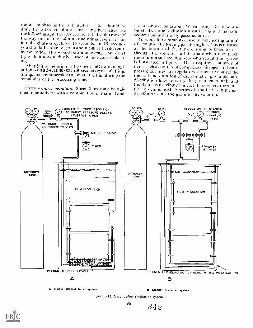
the tiir hubbies is the only agitatit that should bedone. For all other solutions inch ng the washes. usethe following agitation proced tare. Lift the film most ofthe way out of the solution and reimmerse it for aninitial agitation cycle of 15 seconds. In 15 secondsyou should be able to get in about eight lift, tilt. reim-merse cycles. This w ould be about average. but don'ttry to do it too quickly because you may cause tTlash-ing.
fo'r intermittent agi-tation is Ott a 5-Mieultth; each 30 seconds cycle of lifting.tilting, and reimmersing to agitate the film during theremainder of the processing time.
Gascous-hurst agiunion. Sheet films may he agi-tated manually or with a combination of manual and
FURTHER PRESSURE REDUCTIONTO BURST PRESSURE DESIRED
(AVERAGE 10 PSI)jiTWO STAGE REDUCER
(PRESSURE TO 30 PS1)
NITROGENTANK
SOLENOID VALVE
TIMER
FILM IN SCLUTION
°0
PLENUM MUST BE LEVEL)
A
A. Single solenoid burst .system
gascous-hurst agitation. When using the gaseous-burst. the initial agitation must he manual and sub-sequent agitation is by gaseous burst.
Gascous-hurst systems cause turbulence (agitation)of a solution by forcing gas through it. Gas is releasedat the bottom of the tank causing bubbles to risethrough the solution and dissipate when they reachthe solution surface. A gaseous-burst ag.tat.on systemis illustrated in figure 5-11. It requires a numher ofitems such as bottles of compressed nitrogen and com-pressed air, pressure regulators. a timer ti control theinterval and duration of each burst of gas. a plenum.distribution lines to carry the gas to each tank, andfinally a gas distributor in each tank where the agita-tion system is used. A series of small holes in the gasdistributor vents the gas into the solution.
30 PSI 10 PSI REDUCTION TO STANDBYPRESSURE
(APPROX)I 5 PSI
NITROGENTANK
iSTAND-BYBY-PASS
=C
FILM IN SOLUTION
PLENUM ( LEVELING NOT CRITICAL IN THIS INSTALLATION)
B. Standby pressure system
Figure 5-11. Gaseous-burst agitation system.
9 6 34
Nitrogen aas must be used for the developers. This isbecause it is inert and will not oxidize the developingsolution. Air is used in the bleach and fixer. The bleachrequires aeration in order for it to work properly, soair-burst agitation aerates the bleach and agitates thefilm at the same time. The agitation cycle tor gaseous-burst agitation is a 2-second burst every 10 seconds.
The reversal bath, conditioner, washes and stabi-lizer, are not agitated by gaseous burst and manualagitation procedures apply to them. Gasous-burstsystems have some advantages over manual agitationalone. The agitation, being automatic and controlled,may be more uniform than rnanual agitation. Alsothere is less chance of contamination from sloshingchemistry into the other tanks which can happenduring manual agitation. The cost of setting up andmaintaining a gaseous-burst agitation is obviouslymore expensive and is usually not justified unless yourlab does a high volume of color reversal sheet filmprocessing.
Exercises (674):I. I n which step of color reversal film processing is the
solutio: temperature the most critical?
2. At what point in color reversal film processing maynormal room liaht int!1 be used without affecting thefihri?
3. What method of film processing should be usedwhen only a few rolls of film are to be processed?
4. What method of agitation can be used when proces-sing roll film on reels?
5. What method of aunation will cause processingstreaks on roll film that is processed on reels?
6. How are air bubbles dislodued from the film inprocessing?
7. Which solution in the color reversal film processmust be aerated to work properly'?
8. What met hod(s) of agitation is used to processcolor reversil sheet film?
5-7. Slide FinishingMaking color slides is a crit ical procedure. There is a
direct cause-and-effect relationship between eachstep in the process. All error in any step will affect theoutcome of the finished slide. Therefore, you can'tmake allowances for any errors from the time of theexposure until the slide is placed in the mount.
It would he a terrible shame for the slide to be per-fect and then have someone ruin it during the mount-ing step. This next section deals with the propermethods of slide finishing.
675. State the techniques used to MI color resersal
You already know quite a lot about film drying fromprevious discussions in black-and-white film finishing.The diving of color reversal film is not much differentthan for black-and-white. The important thing toremember is that you must do everything properly.
The stabilizer is the last wet step before you dryx'our film. Unlike black-and-white film you do nothave to use a separate wetting agent bath because thewetting agent is included in the stabilizer.
You can dry your film naturally or 1.1tie a film dryer.Avoid excessive heat when drying ;our film because itcan cause your film to curL The film manufacturerrecommends a temperature range of 68° to I 40° F (2(rto 60° C) for film drying but it would be safer not toexceed 125' F (52° ( L
Hang your film up to dry in the conventional man-ner attaching a stainless steel film clip to the bottomof each roll. You can squeegee your film with a softsponge soaked in stabilizer zind then rung out. Squee-gee the film on both sides making only one pass withthe sponge per side.
Re Mire that you wash your film processing reels inhot water to remove any chemicals before letting themdry.
When your film has dried completely. inspect it fordirt or scum. If you find any, the film will have to berewashed and restabilized. Scum on your film canusually be traced to the stabilizer so remix the stabi-ll/Cr while you are rewashing .our film. I n labs that doa lot of color revdsal film processing it is goodpractice to change the stabilizer once weekly.
Exercises (675):I. What is the drying. temperature range for color
reversal film?
97
3 4 .3
2. How should color reversal film be squeegeed?
3. What happens when excessive heat is used to dryyour film?
676. List the advantages and disadvantages of variousmethods of mounting slides.
There are many methods of mounting slides, eachwith certain adv:mtages and disadvantages. Slidesmay, for example, be mounted in cardboard, glass,plastic, and combinations of these materials. We willgo over the basic types and the use of a slide mounter.
Tape and Class. Some of the first film clips to bemounted as slides were mounted between two pieces ofglass taped on the edges to hold the sandwich toi;ether.This is the most time consuming and costly way tomount slides; however, so durable is this method thatit is still practiced today, especially in larger lanternslides. When properly assembled, this type of slidewill survive an amazing amount of abuse short of glassbreakage. Recently, waterproof tapes have been de-veloped which makes it possible to remove almost anytype of surface contaminants this slide may encounter.
Metal With Glass. This type of mounting providesa high degree of protection and is generally less timeconsuming to assemble than tape and glass. Somemountings of this tyre are thicker than standard slidetrays and may tend to jam or stick in automatic slidechangers. Manufacturers of automatic changers haverealized this fact and several have redesigned theirequipment to accommodate this popular method ofslide preparation.
Plastic With Glass. This is the most popular glassmounted slide. It has the best features of the metal andglass type but costs less and is thinner. Some have lessimpact resistance than metal slides; and as is the casewith all glass mounted slides, the tendency to formNewton Rings is present.
Newton Rings. These are optical interference pat-terns that result when humidity causes a very slightirregular separation between two or more optically flatplane parallel surfaces. The pattern appears as avariable area of color similar to that seen on an oilslick or in a soap bubble. To eliminate this trouble-some occurrence, the optical flats must be separated.This can be accomplished at great time loss by scrub-bing the glass surface with scouring powder or at lesstime loss by dusting the film or glass with offset pow-der. When employing the offset powder technique, it isimportant to use a non-toxic, non-abrasive, inertpowder, and a light touch. Stop Offset Spray PowderGrade No. 3 is very effective for this purpose. Thelight touch is a matter of practicing the following
98
technique. Dip a No. 1 artist's brush in the powder,shake excess off; then holding the tip of the brushabout 6 inches above the glass and transparency mat-ting surface, snap the brush sharply with the thumband forefinger much as you would in shootingmarbles. Practice makes perfect! Too much powderand the illustration becomes noticeably speckled.Too little and there are still Newton Rings.
Cleaning Class. Another problem common to allglass-mounting systems is cleaning the glass. This istime consuming and generally involves considerablehand labor. Glass-washing machines have been de-vised but have not proven to be completelysuccessful.The most dependable approach is to soak and washglass in a cleansing solution, followed by clear waterrinse. You then dry with dust-free circulating air orlint-and-wax-free wiping towels. Various agents maybe used in compounding the cleansing solution. Deter-gents of the type recommended for automatic dish-washers, ammonia with water, alcohol with water, and,olutions of tri-sodium phosphate are excellent. Lessdesirable are glass cleaners containing wax and deter-gents with high wax content. Such cleaners imparta gloss that is very susceptible to abrasions whencontacted with wiping towels. Abrasions of this typeserve as dust collectors and impair the quality of theprojected image.
Glassless Mounts. Mounts made of plastic or card-board are by far the most popular method of mount-ing 35-mm slides. They offer advantages such as lowercost, maximum adaptability to projection equipment,no glass breakage, no Newton Ring problems, andeasier mounting. The principal disadvantage is the lossof some protection. The side surfaces of the film aresusceptible to fingermarks and abrasions when givenrough treatment. Under normal circumstances, wherethe entire slide set is protected in storage boxes ortrays, the risk of surface damage is small. Because theadvantages outweight the disadvantages, this hasbecome the most popular way to mount slides.Mounts of this type are supplied in several forms.Some typical constructions are as follows:
I. Hinged Type Where the transparency is posi-tioned in the center of the open mount, the top orhinged flap is brought down over the transparencyand the three sides sealed.
2. Two Part Here the transparency is positionedon the bottom part, a top is placed over the trans-parency and sealed on all four sides.
3. Insert Type--The mount is presealed on threesides where manufactured. The transparency is cut tosize and inserted into the unsealed side ofmount whichis then sealed.
Exercises (676):I. List some advantages of using glass mounts
344
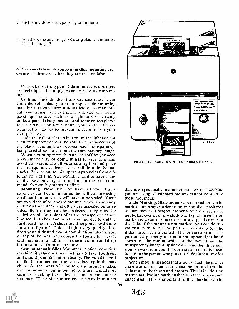
2. 1.ist some (I isadvantages of glass mounts.
3. What are the advantages of using glassless mounts?1)1 sadvant ages?
677. Given statements concerning slide mounting pro-cedures, indicate whether they are true or false.
Regardless of thc type of slide mounts you use. therearc technklues that apply to each type of slide mount-ing,
Cutting. The individual transparencies must be cutfrom the roll unless you arc using a slide mountingmachine that cuts them automatically. To manuallycut your transparencies from a roll, you will need agood light source such as a l'ght box or viewingtable. a pair of sharp scissors, and some cotton glovesto wear while you are handling your slides. Alwayswear cotton gloves to prevent fingerprints on yourtransparencies.
Hold the roll of film up in front of the light and cuteach transparency from the roll. Cut in the center athe black framing lines between each transparency,being careful not to cut into the transparency image.
When mounting more than one roll of fil m you needa systematic way of doing things to save time andavoid confusion. Do all your cutting first and placethc transparencies from each roll into individualstacks. Be sure not to mix up transparencies from dif-ferent rolls of film. You wouldn't want to have slidesof the bas ::. bowling team end up in the base com-mander's monthly status briefing.
Mounting. Now that you have all your trans-parencies cut, begin mounting them. If you are usingcardboard mounts. they will have to be sealed. Thereare two kinds of cardboard mounts. Some are alreadysealed on three sides, and others are unsealed on threesides. Before they can be projected, they must besealed on all four sides after the transparencies areinserted. Both heat and pressure are needed to seal thecardboard mounts. A slide mounting press like the oneshown in figure 5-12 does the job very quickly. Justdrop your slide and mount combination into the sloton top of the press and depress the footswitch. It willseal the mount on all sides in one operation and dropit into a bin in front of the press.
Semi-automatic Slide Mounters. A slide mountingmachine like the one shown in figure 5-13 will both cutand mount your film automatically. The end of the rollof film is trimmed and the roll is lined up in the ma-chine. At the press of a button, the mounter takesover to mount a continuous roll of film in a matter ofseconds. stacking the slides in a bin in front of themounter. These slide mounters use plastic mounts
99
WIN ININNINNA.1.10 AU
I, volt UM.
Figure 5-12. "Seary" model III slide mounting press.
that are specifically manufactured for the machineyou are using. Cardboard mounts cannot be used inthese mounters.
Slide Marking. Slide mounts are marked, or can bemarked for proper orientation in the slide projectorso that they will project properly on the screen andnot be backwards or upsidedown. Typical orientationmarks are a dot in one corner or a clipped corner ofthe slide. If the mount is not marked. you can do thisyourself with a pin or pair of scissors after theslides have been mounted. The orientation mark ispositioned properly if it is in the upper right-handcorner of the mount while, at the same time. thetransparency image is upside down and the film emul-sion is away from you. This orientation mark is a use-ful aid to the person who puts the slides into a tray forprojection.
When mounting slides that are classified, the properclassification of the slide must be printed on theslide mount, both top and bottom. This is in additionto the classification marking that is in the transparencyimage itself. This is important so that the slide can be
34 6
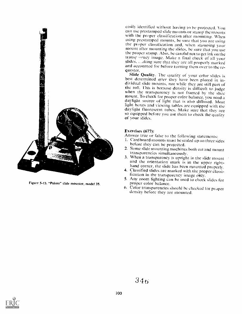
AII1
Figure 5-I3. "Pakon" slide mounter, model 35.
easily identified without having to be projected. Youcan use prestamped slide mounts or stamp the mountswith the proper classification after mounting. Whenusing prestamped mounts, he sure that you are usingthe proper classification and, when stamping yourmount after mounting the slides, be sure that you usethe proper stamp. Also. be careful not to get ink on thetransr 'rcticv image. Make a final check of all yourslides, sure that they are all properly markedand accounted for before turning them over to the re-quester,
Slide Quality. The quality of your color slides isbest determined Wier they have been placed in in-dividual slide mounts. not while they are still part ofthe roll. This is because density is difficult to judgewhen the transparency is not framed by the slidemount. To check for proper color balance, you need adaylight source of light that is also diffused. Mostlight boxes and viewing tables are equipped with thedaylight fluorescent tubes. Make sure that they areso equipped before you use them to check the qualityof your slides.
100
Exercises (677):Answer true or false to the following statements:I. Cardboard mounts must be sealed up on three sides
before they can be projected.2. Some slide mounting machines both cut and mount
transparencies simultaneously.3. When a transparency is upright in the slide mount
and the orientation mark is in the upper right-hand corner, the slide has been mounted properly.
4. Classified slides are marked with the.proper classi-fication in the transparency image only.
5. Any room lighting can be used to check slides forproper color balance.
6. Color transparencies should be checked for properdensity before they are mounted.
3 4 6
Quality Control
HOW MANY TIMES have you bought something,taken it home to assemble it, and discovered a piecemissing. Despite all of your ugly muttering and com-ments about the manufacturer's mistake, the fact isyou are still missing a part. This happens to all of us.It ;cads to the statement, "I wonder where the QC manwas."
This chapter is dedicated to all of those qualitycontrol (QC) people who took a break at the wrongtime. In this final chapter we cover cleanliness, evalua-tion, defects, sensitometry, replenishment, andstorage of materials.
6-1. Observing Laboratory CleanlinessQuality control begins with laboratory cleanliness.
If you feel that laboratory cleanliness is not important,ask yourself whether or not you would want a doctorto operate on you with a dirty scalpel, whether youwould want a service station attendant to put intoyour automobile gasoline that was full of dirt, orwhether you would want a furniture repairman topolish a fine piece of your furniture with a greasypolishing rag. Of course you wouldn't. Neither wouldyou want to work in a dirty laboratory. All the careyou may employ in processing is totally wasted if yoursolutions are contaminated with foreign particleswhich adhere to the surface of the film. What good isfilm if it has a full-length scratch caused by a chemicaldeposit. The purpose of laboratory cleanliness is toprevent a loss of quality from conditions in the labora-tory.
678. State principles and techniques of laborator)and equipment cleanliness.
If you were to examine some of the many publica-tions coveri' g the subject of photography, you wouldnotice that they oftm include a section on defects. Aclose examination of these lists of defects would showyou that a large portion are caused by a lack of labora-tory cleanliness.
Some photographic techniques are even builtaround the concept that the defects can be corrected.For example, print spotting is often accomplished inorder to remove white or gray marks caused by dint,
101
CHAPTER 6
lint, or even chemical dust. Rather than correct thedefect, it is preferable to eliminate the cause. And thecauses can be numerous.
Equipment Storage Room. Check the camera caseand its contents for dust, lint, etc. The camera, whenstored, should have been put away in its case. If the lidof the case is closed, so much the better. As a precau-tion, car:fully dust the camera and pay particular at-tention to the lens, 1-7_specially check the lens forfingerprints. If someone handled it carelessly, theymay have smudged it with oily fingerprints. Theseprints are bad enough in themselves as far as reducingphotographic quality: but since fThLterprints are some-what oily, they will catch and retain more dust part-icles than an unmarked lens. A lens in this conditionmust be cleaned before use.
Carefully examine all the camera accessories andmake sure they are clean. If an ex posure meter is to beused, make sure it is zeroed and that the photocell glassis clean. Check all accessories in a similar manner toassure efficient operation.
In many cases it is advisable to make sure that dustis not present in the camera interior. During opera-tion, this dust could be loosened and deposited on thefilm. If you are using cut film, make sure holders arcclean before loading. Use a brush desiimed to elimi-nate static electricity. Any dusting operations shouldbe carried out in an arca of the lab that is relativelyclean, hut not in the loading room. If you clean yourequipment in the loading room, chances arc that thedust will rise into the air and then settle back on boththe film and the equipment you just cleaned. A roomused for the dusting operation should he well venti-lated or be equipped with some means of dust removal.
Film Loading Room. If possible, a room should beset aside to be used only for loading film. Such a roomshould be kept as clean as possible and free of all dust.The biggest advantage of using a special loading roomover the usual processing or printing room is that theloading room is free of chemicals. Remember, theroom should be used for only this one purpose-load-ing film-not for storaLte, extra processing facilities, etc.
If you are forced to use some type of processing labfor loading, be especially careful of chemical con-tamination. Whether the lab is used for contact print-ing or negative processing, the fact remains photo-graphic chemicals will be in evidence. Consequently,
34 /
cleanup procedures must be rigid. You will sat e con-siderable effort if the lab is maintained with a wet sideand a dry side. The dry side is always dry. Absolutelyno solutions or chemicals should cross the imaginaryline down the middle. Even with these precautions,carefully inspect the area you will be using for loadingfor any evidence of chemical deposits. Also, be carefulof any water that might have splashed on the loadingarea. Take all the necessary precautions in providingyourself with a clean loading surface.
Mission Accomplishment. The moment you go outon a mission you are exposing your film holders, filmpack adapter, or other film containers to a dusty anddirty environment. Keeping the holders clean duringthe mission is largely a matter of common sense. Don'tlay them down in the dirt or on any surface that in-creases the chance of their becoming exposed to anyform of matter which can enter the holder. Not onlyshould the holders be protected, so should the cameraand related equipment. Many of the precautions to betaken are obvious. Also, look for the not-so-obvioussituations where particles of foreiL,n matter arepresent.
Unloading and Processing. This is one of the mostcritical stages of handling film since the film is in anarea that more than likely is used for both unloadingand processing purposes. Film should be afforded thesame treatment during unloading as when it wasloaded. Before unloading, thoroughly clean the un-loading space. If you dust it off, use a rag that willpick up the dust rather than simply causing it tobecome airborne. If there is a possibility that chemi-cals may be present on the loading surface, wipe thesurface with a damp rag or sponge in order to removethe che- 'cals. Then let the surface dry before proceed-ing with the unloading process. Make certain that thesponge or rag you are using for this purpose is cleanand has not been previously used to wipe up hypo orsome other chemicals. The use of a dirty rag will nothelp matters.
If you are going to delay processing till later, besure the container used to store the exposed but un-processed film is clean. Use of the original film box isadvisable, but only if it has been kept clean since youremoved the unexposed film.
If you are going to process the film at this time, youshould have already checked the wet side of the lab forclean trays and associated equipment before mixingthe working solution of developer. Many times, a labmay not have been used for a considerable length oftime. If this has happened, the trays may have col-lected dust. Also, check the tray of hypo. It may havebeen left full for economy reasons, but if stored inthis manner for a considerable time, it could be dirtyto the extent that it should be discarded. False econ-omy here could ruin your negatives, and it wouldcertainly be cheaper to prepare a fresh batch of thisinexpensive chemical.
Negative Drying. After you have developed, fixed,and washed your negative, it must be dried. This is afairly critical step. You could drop a wet negative on
the floor, rewash it, and still end up with an ac-ceptable product. However, if you hang a negative todry in a dusty atmosphere and the particles of dirtadhere to the emulsion until it is dry, no amount ofadditional washing will remove them. If the negativesare hung on a line to dry, the entire room must be keptclean. If at all possible, use a drying cabinet that can beheated to speed up the drying process and one thatcirculates filtered air to eliminate as much dust aspossible. The sooner the negatives are dried, the lesschance there is of dust sticking to the emulsion.
After the negatives have been dried, they must stillbe protected. In general, the protection from thispoint on is not quite as eritical as before. Negativesshould be placed in separate negative preservers as aprotection from dust, scratches, etc. If more than onenegative is to be placed in the preserver, a sheet ofprotective paper must be placed between negatives.This paper will keep the negatives from rubbingagainst each other which is a primary cause of abra-sion marks. By all means, do not allow fingerprints toremain on the surface of the negatives. If the finger-prints arc cleaned off immediately, they are readilyremovable. If they have been on for some time, theymay be difficult, if not impossible, to remove,
Cleanliness During Printing. During this stage ofthe photographic operation, you will find many situa-tions where cleanliness saves much additional work.The first consideration should be given, as mentionedbefore, to maintaining a wet and a dry side in thelaboratory. The area of the lab used for printing,whether projection or contact, must be kept clean anddry. During the printing operation, much unexposedand exposed material will be laid out on, or alongside,the printer. If water or chemical solutions havesplashed on these surfaces. many of your prints willbe spoiled before they are even processed.
After you have processed your prints, your handsmay be moistened with either water or one of thechemical solutions. If it is just water on your hands,simply dry them off on a clean towel, not one pre-viously contaminated with chemicals. If your handsare wet from contact with the hypo or developer,wash them off with clean water before using the towel.And be sure you dry them before returning to the dryside of the lab.
Another point to watch when using the wet side ofthe lab is to avoid all chances of splashing any of thesolutions during processing. If you splash, the solu-tions will get on the floor and on your clothing. Thus.the solutions can be transported to the dry side. Ifhypo is on your clothing, you may accidently ruin theprint. If solution falls to the floor, the effects arc notquite as noticeable, at least at this time. However, youwill track the hypo or other solutions around thefloor where they will dry. After the chemicals are dry,they assume their original powdery form. As you walkback and forth, you stir up these chemicals, and theybecome airborne, eventually to fall back on all flatsurfaces. Some of the flat surfaces could be film andpaper. If you find a number of pinholes (especially
1023 4

noticeable in dark backgrounds) on your negatives,this could be the cause. The same type of markingswould also be noticeable on prints.
Laboratory Cleanup. An important factor inquality production is the general state of cleanlinessin the laboratory. From time to time it may becomeyour job to clean the lab. The use of a broom tosweep the floor is not advisable. Rather, use a dust-mop type of sweeping device that will not throw dustand chemicals into the air. Following this operation,a wet mop should be used--rinse and wring it outfrequently. The use of a dirty mop will do more harmthan good.
Sinks should be well-rinsed with clean water inorder to remove all traces of chemicals. Edges andback panels that cannot be flooded w ith water shouldbe wiped with a clean damp rag or sponge. Water ischeap at any price when the lack of its use can damageyou r product.
During a general lab cleanup, do not forget to cleanchemicals from walls, bottles, graduates, timers, andother equipment. Chemicals from the handle of atimer or a wall could easily transfer from such a sur-face to your hands and then to a negative or print. Atthe same time, check the safelight filters. Chemicaldeposits here ce ,Id contribute to decreased illumina-tion along with other ill effitts.
After a lab has been generally cleaned, it is advisableto use a vacuum cleaner to remove dust that hassettled into corners of the room and other areas oftenmissed during usual cleaning. If a vacuum cleaner isavailable, use it to remove the dust and lint from itemsof equipment in the lab. From time to time use thevacuum cleaner to clean the inside of a contact printer,for example. Removal of dust from this area may saveyou a reprint caused by the deposit of dust or lint on anegative or print.
The ideal situation in a laboratory would be to haveit in a surgically clean state. Since this is not pos-sible, strive for maximum cleanliness. Track in as lit-tle dirt as possible, be as clean as you can in youroperations and avoid splashing chemical solutions,provide for regular cleanup sessions, maintain dry andwet sides, and use a room fo i. its intended purpose.Cleanliness in photography is just as important ascorrect technical procedures.
Dust can raise havoc in any photographic processfrom the beginning to the final product. Dust oftencontains small particles or crystals of quartzsuchparticles can readily scratch glass surfaces such asprinter glasses, lenses, etc. When cleaning criticalsurfaces of this type, be especially careful that you usethe proper kind of cleaning material. If you rub quartzparticles into the surface as you are cleaning, you takethe chance of scratching it. It may be necessary to dustthe surface lightly with a fine-haired brush or use agentle air jet from a hand syringe prior to cleaning offthe fingerprints, etc.
If a liquid is required to c, plete the cleaning job,remember that water will eliminate most chemicaldeposits. When it is necessary to use a solvent other
than water, use as little solvent as possible and con-sider all safety precautions connected with its use.Never soak a piece of equipment in the solvent. Theuse of an excessix e amount may prove to be moredamaging than if the item were left uneleaned. Forexample, cleaning a lens by soaking it with alcoholwill remove the fingerprints, but it may also sep-arate the lens elements. Or the excessive use of sol-vents on a tiled laboratory floor may loosen the tilesafter repeated applications.
After you have done as much as you can with re-spect to maintaining the cleanliness of a laboratory,you have gone far down the road of quality control.Even so, dust, chemicals, lint, etc., will still be a prob-lem. If so, the next section covering visual qualitycontrol will serve as another check on cleanliness.
Exercises (678):I. Why should you avoid cleaning your carnera equip-
ment in the loading room?
2. Describe the dry side of a lab.
3. How should down-loaded film be stored?
4. What happens to chemicals when they are splashedon the floor?
5. How much soivent should you use to clean anyitem?
6-2. Employ Visual EvaluationWhile it is not truly scientific, visual examination
can greatly improve the quality of your work. Bychecking your negatives, slides and prints for properdensity, contrast, and absence of defects, you canidentify what you are doing right and where yourproblems are coming from. Remember, if you can'tlook at your own work and take pride in it, you can'texpect the requestor to think much of it either.
103
679. Given a list of print or negative defects, identifythe cause of each one.
Visual Examination. The key to visual examina-tion is to have an appropriate check list and a consis-tent viewing standard. For example, you may develop
3 4
a list that covers density. contrast. sharpness. andmechanical (pinholes, scratches. etc.) and chemical(stains. etc.) defects. You then follow a consistentviewing pattern. You should a lway look at your nega-tives. slides, or prints, using the ae light table orviewing light. etc. Only in this v y can you have aconsistent basis for making a ju !ment.
What to Look For. First yc should look at thedensity of the product. Too much exposure producesnegatives that are too dense, prints that are muddy,and slides that are thin. Too little exposure leads tothin negatives and prints and saturated slides. Howabout the contrast? There should be detail in both thehighlights and shadows unless you are going for aspecial effect. Negative contrast is a product of de-velopment, so if your negatives are too contrasty. youmight need to cut your development time. If they aretoo thin, you must increase the development time. Thecontrast of prints can be altered through choice ofpaper grade. filter, or. to a limited degree, develop-ment. Slides, unfortunately, can only be corrected bycopying. which normally results in a product that isslightly inferior to the original. Sharpness is a productprimarily of your focusing. It is too late if your nega-tives or slides are off. If you have a soft print, you canreprint. Consistently soft results should cause you tocheck your equipment or your technique! Finally,there are innumerable mechanical or chemical defectscaused by defective cameras, accessories, improperhandling, or contaminated chemicals. The following isa sampling of what you might encounter:
a. The image appears hazy and lacking in contrast.(1) The sun was shining into the lens. Remem-
ber, it is necessary to protect the lens from the directrays of the sun when you take a photograph against thelight. Light striking the lens causes a hazy. indistinctimage. Sometimes, bright light striking the lens pro-duces large circles which partially obscure the image.
(2) Your lens is dirty. Many times, dust or con-densed water vapor on the lens results in hazy pictures.Remember to clean your camera lenses frequently.
(3) Overexposure.(4) The negative is fogged.
h. You observe small transparent and irregularlyshaped spots. This is often caused by dust settling onthe film before the exposure. It can be corrected bycleaning the camera interior and by loading the film ina clean environment.
c. Small circular transparent spots. These areproduced by small air bubbles on the surface of thefilm during development. This problem can be takencare of by proper agitation.
d. When a negative emulsion has a wrinkled ap-pearance (reticulation)this is produced by an abruptor sudden swelling or contraction of the film. Sharpdifferences in the temperatures of successive proces-sing solutions and/or insufficient hardening of thegelatin are the usual causes of reticulation.
e. The image is not sharp.(1) The subject moved. If this is the case, any
stationary objects included in the picture will be sharp,
assuming that they are in focus. Lack of sha rpness willbe confined to the parts that were in motion at the timeof exposure.
(2) The camera moved. If this is the case, there isa general blurring of the image. Sometimes, you willobserve double lines made by the subject. Rememberthat the average photographer cannot hold the cameraperfectly still for an exposure longer than 1 30 second.
(3) The subject is not in focus. If other parts orobjects of your negative are sharply defined, whileobjects at other distances are not sharp, the camerawas not set for the proper distance. You made an errorin using the rangefinder. focusing on the ground glass.or selecting the correct focusing distance on the dis-tance scale.
Dense areas of varying width along the edge ofthe negativethis condition is produced on roll filmwhen the film is not tightly wound upon loading orremoval from the camera.
g. The image on your negative is partially a posi-tive. This is due to reversal of the image and is some-times caused by hypo in the developer. More often. itis the result of a brief exposure to light during develop-ment.
h. A yellow stain appearing after the negative isdrythis may be caused by insufficient fixation or theuse of an exhausted fixing bath. Small yellow orbrownish spots are due to air bubbles on the filmduring fixing.
i. Pink stains are due to traces of the dye applied tothe back of certain films for the purpose of preventinghalation. The stains can often be removed by placingthe film in a 5-percent solution of sodium sulfite afterwashing. The film should then be returned to the washfor an additional 5 or 10 minutes. If the negative isdry, it should be allowed to soak in water for 10 to 15minutes before being placed in the sodium sulfitesolution.
j. Blisters or circular pits in the emulsion whenviewed from the surfacethe blisters may be pro-duced by concentrated developing solutions. de-veloper or fixing solutions which are too warm, insuf-ficient rinsing between developing and fixing. or anold or incorrectly compounded solution.
k. Grayish whites over the entire print are usuallycaused by chemicals or light fog. They also may becaused by insufficient potassium bromide in thedeveloper, too long a development time. or the use ofoutdated paper.
1. A grayish-mottled or granulated appearance ofthe edges or entire print is usually caused by under-exposure and forced development. This effect mayalso be caused by using outdated paper. Moisturewithin the paper or exposure to chemical fumes. suchas ammonia, can also produce this effect.
m. A purple discoloration of the print is caused bylack of agitation in an acid stop bath.
n. White deposits over the entire surface of a printare caused by milky hypo baths and incorrectly mixedor impure chemicals.
104 3

NOTE: The above is not an inclusive list of negativeand print defects. Most manufacturer's of photographicmaterials and chemicals have charts listing defects andtheir causes. Such lists are very helpful as you strive toproduce top quality work.
Exercises (679):
I. Identify the cause of the following defects.a. Thin slides.
b. Muddy prints.
c. Hazy negatives.
d. Negative has wrinkled appearance.
e. Negative is partially positive.
f. Small yellow or brownish spots on the film.
g. Grayish whites on your print.
h. Purple discoloration to the print.
6-3. Solution Certification
Suppose you had 30 sheets of film that were veryimportant and could not be reshot. How can you be surethat, when you process them, they will come outproperly? You might mix new chemistry or process byinspection. But how will you know beforehand that thenew chemistry is good or that the safelight will not fogthe film? What you need to know is whether theprocessing solutions are working properly.
The best method of ensuring that your process is incontrol is to certify your chemistry.
680. Given a list of specific gravity readings, matchthe readings to the solutions.
The first check that should be made on all solutions isa specific gravity reading. It is a quick check to see if the
mix is complete. Specific gravity is the ratio of mass ofa given volume of substance to an equal volume ofdistilled water at 10 F .
Mass of a known volume of a substanceSpecific GravityMass of an equal volume of water
Specific gravity readings will vary from one batch ofsolutions to another because of various factors involved(quality of chemicals, inaccurate scales, etc.). Thisrequires that uppe- and lower control limits be set. If thesolution does not fall within these control limits, furtheranalysis can be made to determine the cause. If thespecific gravity reading goes beyond the upper controllimits, it might indicate that more than the formulaamount of an ingredient has been used or the solution hasnot been diluted properly. A reading which is below thelower limits might indicate that an ingredient has beenleft out of the solution or that too much water has beenadded.
For practical purposes the hydrometer is generallyused to calculate specific gravity of liquids. Thehydrometer is calibrated to read 1.000 in pure, distilledwater at 60° F. A temperature change will have a directeffect on the ,)ecific gravity reading. For every increaseor decrease of 5° F, 0.001 must be added or subtracted.Research indicates that the temperature corrections formost photographic solutions whose specific gravity fallsbetween 1.100 and 1.200 is very close to 0.003 per 10° Ftemperature change.
Specific gravity readings using a hydrometer requirethat the hydrometer cylinder be on a level support.Readings are taken at the top of the meniscus as seenalong the side of the hydrometer stem (see fig. 6-1).
The following are sample specific gravity readings forsolutions that you are likely to use each day.
105
Solution Specific Gravity
DK-50D-76D-72HYPO
1.0341.0841.1051.074
Exercises (680):
1. What is the purpose of a specific gravity reading?
2. Select from the list of specific gravity readings incolumn A, one reading appropriate for eachsolution in column B.
Column A Column B
(1)1.075. a. D-72.(2) 1.100. b. D-76.(3) 1.050. c. HYPO.(4)1.090.(5) 1.001.
71
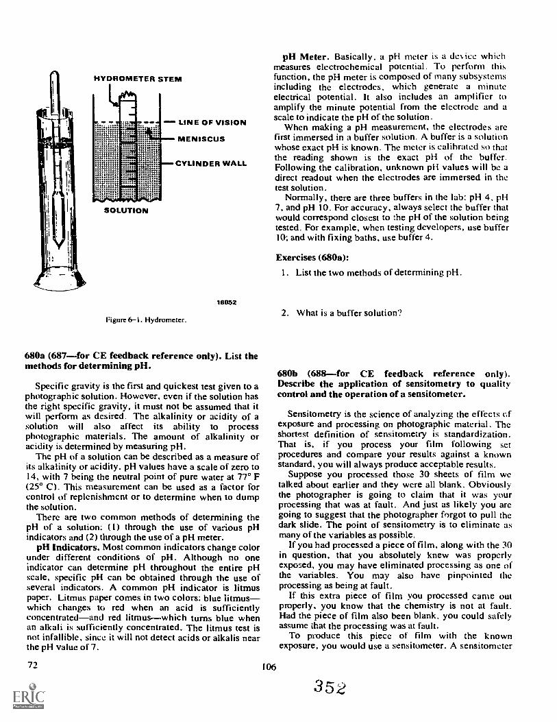
HYDROMETER STEM
SOLUTION
LINE OF VISION
MENISCUS
CYLINDER WALL
Figure 6-1. Hydrometer.
18052
680a (687for CE feedback reference only). List themethods for determining pH.
Specific gravity is the first and quickest test given to aphotographic solution. However, even if the solution hasthe right specific gravity, it must not be assumed that itwill perform as desired The alkalinity or acidity of asolution will also affect its ability to processphotographic materials. The amount of alkalinity oracidity is determined by measuring pH.
Thc pH of a solution can be described as a measure ofits alkalinity or acidity. pH values have a scale of zero to14, with 7 being the neutral point of pure water at 77° F(25° C). This measurement can be used as a factor forcontrol of replenishment or to determine when to dumpthe solution.
There are two common methods of determining thepH of a solution: (1) through the use of various pHindicators and (2) through the use of a pH meter.
pH Indicators. Most common indicators change colorunder different conditions of pH. Although no oneindicator can detcrmine pH throughout the entire pHscale, specific pH can be obtained through the use ofseveral indicators. A common pH indicator is litmuspaper. Litmus paper comes in two colors: blue litmuswhich changes to red when an acid is sufficientlyconcentratedand red litmuswhich turns blue whenan alkali is sufficiently concentrated. The litmus test isnot infallible, since it will not detect acids or alkalis nearthe pH value of 7.
72
pH Meter. Basically. a pH meter is a del, ice whichmeasures electrochemical potential. To perform thisfunction, the pH meter is composed of many subsystemsincluding the electrodes, which generate a minuteelectrical potential. It also includes an amplifier toamplify the minute potential from the electrode and ascale to indicate the pH of the solution.
When making a pH measurement, the electrodes arefirst immersed in a buffer solution. A buffer is a solutionwhose exact pH is known. The meter is calibrated so thatthe reading shown is the exact pH of the buffer.Following the calibration, unknown pH values will be adirect readout when the electrodes are immersed in thetest solution.
Normally, there are three buffers in the lab: pH 4, pH7, and pH 10. For accuracy, always select the buffer thatwould correspond closest to the pH of the solution beingtested. For example, when testing developers, use buffer10; and with fixing baths, use buffer 4.
106
Exercises (680a):
I. List the two methods of determining pH.
2. What is a buffer solution?
680b (688for CE feedback reference only).Describe the application of sensitometry to qualitycontrol and the operation of a sensitometer.
Sensitometry is the science of analyzing the effects Gfexposure and processing on photographic material. Theshortest definition of sensitometry is standardization.That is, if you process your film following setprocedures and compare your results against a knownstandard, you will always produce acceptable results.
Suppose you processed those 30 sheets of film wetalked about earlier and they were all blank. Obviouslythe photographer is going to claim that it was yourprocessing that was at fault. And just as likely you aregoing to suggest that the photographer forgot to pull thedark slide. The point of sensitometry is to eliminate asmany of the variables as possible.
If you had processed a piece of film, along with the 30in question, that you absolutely knew was properlyexposed, you may have eliminated processing as one ofthe variables. You may also have pinpointed theprocessing as being at fault.
If this extra piece of film you processed came outproperly. you know that the chemistry is not at fault.Had the piece of film also been blank, you could safelyassume that the processing was at fault.
To produce this piece of film with the knownexposure, you would use a sensitometer. A sensitometer
352
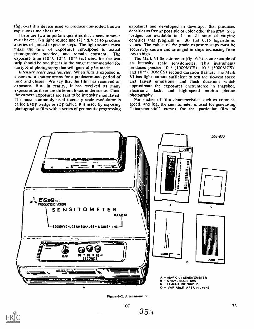
(fig. 6-2) is a device used to produce controlled knownexposures time after time.
There are two important qualities that a sensitometermust have: ( I) a light source and (2) a device to producea series of graded exposure steps. The light source mustmake the time of exposures correspond to actualphotographic practice, and remain constant. Th..exposure time (10-2, 10-3, 10-4 sec) used for the teststrip should be one that is in the range recommended forthe type of photography that will generally be made.
intensity scale sensitorneter. When film is exposed ina camera, a shutter opens for a predetermined period oftime and closes. We say that the film has received anexposure. But, in reality, it has received as manyexposures as there are different tones in the scene. Thus,the camera exposures are said to be intensity modulated.The most commonly used intensity scale modulator iscalled a step wedge or step tablet. It is made by exposingphotographic film with a series of geometric progressing
exposures and developed in developer that producesdensities as free al... possible of color other than gray. Stepwedges are available in I I or 21 steps of varyingdensities that progress in ,30 and 0.15 logarithmicvalues. The values of the grade exposure steps must beaccurately known and arranged in steps increasing fromlow to high.
The Mark VI Sensitometer (fig. 6-2) is an example ofan intensity scale sensitometer. This instrumentsproduces precise i0-2 (1000MCS), 10-3 (5000MCS)and 10-4 (130MCS) second duration flashes. The MarkVI has light outputs sufficient to test the slowest speedand fastest emulsions, and flash durations whichapproximate the exposures encountered in snapshot,electronic flash, and high-speed motion picturephotography.
For studies of film characteristics such as contrast,speed, and fog, the sensitometer is used for generating"characteristic" curves for the particular film of
231-677
n0. EMIG INCPRODUCTS DIVISION
MARK VI
EDGERTON. GE RMESHAUSEN & GRIER. INC. i
\I
A
Figure 6-2. A scnsitometer.
107
3 53
A MARK vl SENSITOMETER8 GRAYSCALE BOXC PLASHTUBE SHIELD
VARIABLEAREA PLTERS
73

interest. This should be done using the manufacturers'recommended exposure and developed schedule.
To operate the Mark VI, follow these steps:( I ) Plug power cord into an outlet. Be sure to ground
the plug to prevent shock hazard.(2) Switch the power on.(3) Press exposure circuit selector button for desired
flash duration.(4) Add filters or fight attenuators if necessary.(5) Turn the room lights off.(6) Place film to be exposed over the step tablet,
emulsion down.(7) Slide film into proper groove.(8) Hold the film in place at one end and lower the
platen onto the film.(9) Pull arm down until clicking sound indicates that
the tube has flashed.(10) Process film as usual.
Exercises (680b):
1. Sensitometry is the science of analyzing the effectsof and on
photographic materials.
2. The one-word definition of sensitometry is
3. Why is sensitometry applicable to quality?
4. Which of the following is not an operation of theMark VI se;sitometer?
a. Select the desired exposure flash setting.b. Add filters or attenuators?c. Adjust the calibration control until the meter
reads the density required.d. Slide the film into the groove and lower the
platen onto the film until a clicking sound hasindicated that the flash tube has fired.
680c (689for CE feedback reference only). Identifythe procedures for operating a densitometer.
After you have produced a sensitometric strip andprocessed it, your next step is to measure the density ofthe individual steps. Density is the logarithm of thereciprocal of the light transmittance, stated D=log10(I/1'). The densitometer uses this method and givesvalues that ( I) give numbers that increase in size and thesilver deposit increases in density and (2) corresponds tothe way the eye sees light intensity differences.
74
Most Air Foice laboratories use direct reading,electronic densitometers. The MacBeth QuantalogDensitometer, TD-102, shown in figure 6-3, is typicalof the kind of instrument that is generally used. lt maybe operated under any normal lighting condition, sinceambient light does not affect its optical system. Theinstrument is equipped with a turret containing lbur filterpositions. The filters installed in the turret are the red,Wratten No. 92; the green, Wratten No. 93; the blue,Wratten No. 94; and a No. 106 for visual operation. Forcolor densitometry, you use the three colored filters; forblack-and-white densitometry, place the turret in thevisual position.
Except for minor differences, all densiv:,meters areused in the same manner. To operate the TD-102densitometer, you must first zero adjust the instrument.To zero adjust the TD-102:(1) Rotate the zero-adjust knob to turn the power on.after the instrument has been plugged into a suitablepower line whose voltage is stabilized.
(2) After a 30-minute warmup, with no sample in place,rotate the filter selection control (the gold filter trimcontrol to the bottom position), and depress the snoutlever. Turn the zero-adjust knob further clockwise untilthe needle is properly zeroed. These steps can berepeated for red, blue, and green when zeroing in forcolor work.
To calibrate the TD-102 after zeroing:
(1) Place the internal calibration reference in themeasuring beam by moving the calibration referencelever backwards until you feel it "click in."
(2) Depress the snout lever.
(3) Adjust the calibration control until the meter readsthe density indicated on the tag adjacent to this control.
(4) Remove the internal calibration reference from themeasuring beam.(5) Recheck your zero and calibration settings.
NOTE: Fine needle adjustments can be made byrotating the filter trim control knob that is in the bottomposition.
Once you have determined that your densitometer is incalibration and is operating correctly, you are ready tomake density readings of your sensitometric strips.Readings are made by lowering the snout lever down oneach step of the processed sensitometric strip andrecording them in proper sequence.
Exercises (680c):
1. A is a device used to measure thedensities of a piece of film.
107a
3 5 ei
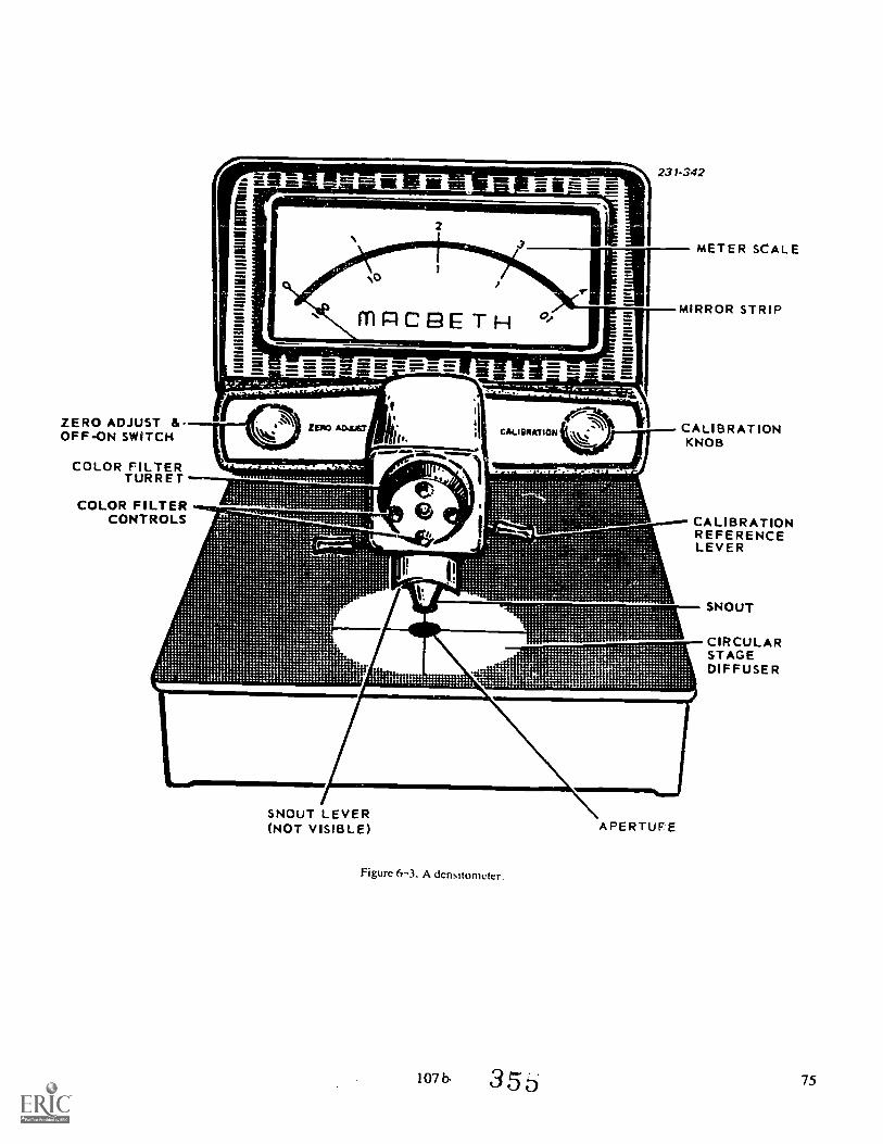
ZERO ADJUST &OFF-ON SWITCH
COLOR FILTERTURRET
237-342
METER SCALE
MIRROR STRIP
CALIBRATIONKNOB
COLOR FILTERCONTROLS CALIBRATION
REFERENCELEVER
SNOUT LEVER(NOT VISIBLE) APERTUFE
Figure 6-3. A densitometer.
10Th 3 5 6
SNOUT
CIRCULARSTAGEDIFFUSER
75
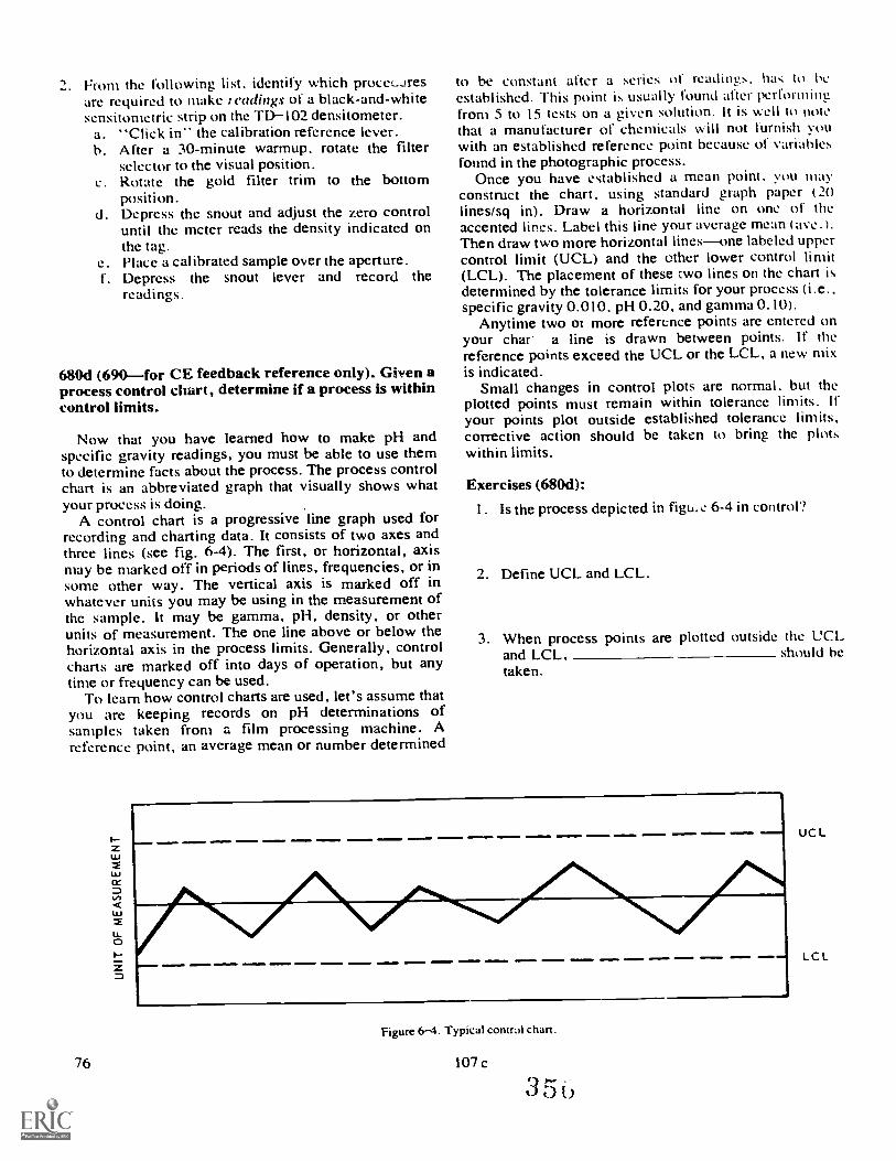
2. From the following list. identify which procet..Jresare required to make readings of a black-and-whitesensitometric strip on the TDIO2 densitometer.
a. "Click in" the calibration reference lever.b. After a 30-minute warmup, rotate the filter
selector to the visual position.c. Rotate the gold filter trim to the bottom
position.d. Depress the snout and adjust the zero control
until the meter reads the density indicated onthe tag.
e. Place a calibrated sample over the aperture.I. Depress the snout lever and record the
readings .
680d (690for CE feedback reference only). Given aprocess control chart, determine if a process is withincontrol limits.
Now that you have learned how to make pH andspecific gravity readings, you must be able to use themto determine facts about the process. The process controlchart is an abbreviated graph that visually shows whatyour process is doing.
A control chart is a progressive line graph used forrecording and charting data. It consists of two axes andthree lines (see fig. 6-4). The first, or horizontal, axismay be marked off in periods of lines, frequencies, or insome other way. The vertical axis is marked off inwhatever units you may be using in the measurement ofthc sample. It may be gamma, pH, density, or otherunits of measurement. The one line above or below thehorizontal axis in the process limits. Generally, controlcharts are marked off into days of operation, but anytime or frequency can be used.
To learn how control charts are used, let's assume thatyou are keeping records on pH determinations ofsamples taken from a film processing machine. Areference point, an average mean or number determined
76
to be constant after a series of readings. has to he
established. This point is usually found after perfonnitirfrom 5 to 15 tests on a given solution. It is well to ilotethat a manufacturer of chemicals will not furnish youwith an established reference point because of variablesfound in the photographic process.
Once you have established a mean point, you mayconstruct the chart, using standard graph paper (20lines/sq in). Draw a horizontal line on one of theaccented lines. Label this line your average mean (ave.).Then draw two more horizontal linesone labeled uppercontrol limit (UCL) and the other lower control limit(LCL). The placement of these two lines on the chart isdetermined by the tolerance limits for your process (i.e.,specific gravity 0.010, pH 0.20, and gamma 0.10).
Anytime two or more reference points are entered onyour char a line is drawn between points. If thereference points exceed the UCL or the LCL, a new mixis indicated.
Small changes in control plots are normal. but theplotted points must remain within tolerance limits. Ifyour points plot outside established tolerance limits,corrective action should be taken to bring the plotswithin limits.
Exercises (680d):
I. Is the process depicted in figu, e 6-4 in control?
2. Define UCL and LCL.
3. When process points are plotted outside the UCI.,and LCL, should betaken.
am.1
Figure 6-4. Typical contral chart.
107 c
UCL
LC L
6-4. Replenishment
Through use or just through age, photographicsolutions lose some of their abilities to perform that theyhad when they were freshly prepared. Physical changestake place whether or not the chemicals are actually usedto process photographic materials.
In this section we discuss the physical changes thatphotographic solutions undergo through use, how todetect these changes, and different methods ofreplenishment that can be used.
681. State the principles and procedures related tothe replenishment of developers.
Some of the factors that alter the characteristics ofphotographic solutions are: loss of solution throughsolution carryover, oxidation through use or fromimproper storage conditions, chemical reaction throughprocessing of sensitized materials, and dilution alsocaused by solution carryover.
For many labs, the gradual loss of a solution'sprocessing abilities is no big problem becauseallowances can be made by increasing processing timt-s
and the relatively small batches of chemistry can bediscarded and new chemistry mixed if things get too farout of hand. However, many large photo labs use largevolumes of solutions, especially in machine processorswhere "dumping" of the chemicals (when they nolonger meet standards of processing) would be highlyimpractical as well as expensive. Here, replenishmert ofsolutions to revive them and make them work properly isvery important. Chemistry replenishment is economical
also saves the time it would take to remix solutionseach time they were not performing properly.
Effects Resulting From Use of Developers. Withuse, the activity of the developing solution changes. Theused developer becomes slower in its reaction; and as aresult, a longer development time is needed to achievethe same result. There is an effective loss of film speedas the developer deteriorates. The change in the activityof the used developing solution is the result of chemicalchanges that take place within the solution.
Chemical changes in the developer are the result of thefollowing:
Chemical reaction of the developing solution withthe silver halides of the emulsion.
Action of the air upon the solution (oxidation).
107.d 35 77
I oss of solution through carryover to the follow-ing tank.
Dilut Um of the developer (when a predevelop-ment bath is used). The most significant of the chemi-cal changes are those caused by the chemical reactionof the developing solution with the silver halides andt he air.
k the developing solution reacts with the silverhalides, metallic silver is formed in the emulsion andcomplex reaction byproducts are formed in the de-veloping solution. -Die most significant of these reac-tion byproducts are the bromides and iodides. Thereason they arc significant is that they have a restrain-ing effect on the developing agent. The developer-silyer-hahde reaction tends to cause the pH of thedeveloper to drop.
the reaction of the developing solution with thesurrounding air creates unuseful and unavoidableoxidation byproducts. Oxidation of the developingsolution tends to raise the pH of the developing solu-tion. The reason the pH tends to rise is that sulfonatesare formed as a result of the oxidation process, andthese sulfonates are alkaline.
In addition to the depletion of the developingagents. there is a simultaneous depletion of the alkaliand sulfite. However, the restraining action of theiodides and the bromides which accumulate in thedeveloping solution is more significant than thereduction of developing agent. alkali, and sulfite.
Detection of Developer Deterioration. You can-not detect the degree of exhaustion of the develop-ing solution just by measuring its pH. The pH islowered by reaction between the developing agentsand the silver halides, but it is raised b,. the reactionbetween the developing agents and the air. Nor canN l)eciIie gravity measurement by itself provide youwith much useful information about the used develop-ing solut ion.
You can cheek the deterioration of the developingsolution through detailed solution analysis. In such aprocedure. vou must analyie the solution for Metol.hydroquinone. bromide, sulfite. and carbonate con-tent. I hrough this type of analysis, you get exact in-formation about the degree of deterioration.
If neither pl I measurement nor specific gravitymeasurement can give a concrete indication of solu-titm deterioration. and complete analysis of thedeveloping solution is not practical. how can youdetect deterioration of the developing solution? Oneof the easiest methods for doing this is to monitor theresults that are produced by the solution by usingsensitometric methods and using them frequently.
If you process sensitornetric control strips when thesolution is tresh and while processing. you will be ableto spot any signif eant changes in the solution.
If you have serious doubts about the quality of agiven solution. you can always process a control stripby itself to verify the adequacy of the solution. Thiswill avoid possible damage to critical film.
1-o determine solution perlormancc. vou coinparcthe results of characteristic curves prepAred I rom thetests made in used solution tt it h the cha a deristiccUrVes prepared when the solution Was fresh. Changesin the characteristic curves are normally used as thebasis for determining when the devdoping solution isno longer adequate.
Developer Replenisher. Not only must the replen-isher solution add chemicals that have been used up inthe processing of sensitiied materials but ako the re-plenisher must lower t he concentration of the iodidesand bromides that have accumulated in the used solu-tion. Satisfactory replenkher formulas depend uponthe processing conditions used. the type of solution.and the kind of photographic material being proc-essed. Storage conditions. frequency of use of thedeveloper, the amount and type of agitation. oxida-tion, how much the sensitind material was exposed.and the degree of development also figure into thecompounding of a satkfaetory replenisher.
The constituents normally found in the replenishersolution are water, reducing agents (example. metol).sodium sulfite. and an alkali (example. sodiumcarbonate). The replenisher contains no bromide: infact, as previously stated, it is normally designed toadd a sufficient amount of solution to the existingdeveloper to dilute the accumulated bromides andiodides to a suitable level. Most developer formulashave accompanying replenisher formulas so that youdo not have to determine the exact amounts of each ofthe chemicals that are to be kidded. However, remem-ber that an emergency replenisher solution can usuallybe compounded by mixing a modified solulion of thedeveloper itself. omitting the bromide. Solutionsprepared with such a replenisher solution cannot bcexpected to maintain the consistency of results thatyou would get if you used a properly compoundedreplenisher. There will, however, be a significantextension of the useful hfe of the developing solution.
NOTE: There are packaged replenishers which arcsimple and easy to use and therefore do not call forcompounding of a formula. !n fact, many colorprocessing kits come with replcnishers.
Methods of Developer Replenishment. Replenish-ment is normally done in one of two ways:
a. By intermittently adding git en amounts of re-plenisher as specific amounts of material hate beenprocessed in the solution. Normally. the manu-facturer indicates how many milliliters of%replenisherto add per square foot of processed film. It is there-fore necessary to keep a running total of how man\sheets or rolls of film have been processed. I hroughcalculation you can determine hot% limn\ yolk 0.sheets to the square foot.
Fhis method of replenishment is normally used inhand processing. The correct procedure is to take outan adequate amount of solution from the tank. Thenyou pour in the correct amount of replenisher. Finallyyou bring the solution up to let el with the old solutionthat you carried out in step one. This presents the
78 108
35

tanks from overflowing, which will happen if yousimply pour in the replenishment solution.
b. By continually adding replenisher at a calculatedrate of flow, when processing is being done contin-uously. This is used in machine processing and isnormally done through a pumping system which iscontrolled by a metering system.
NOTE: In certain cases the developer solution isnot replenished, but the processing time is graduallyincreased as more and more sensitized material ishandled.
End Point for Developer Replenishment. Theprocess of replenishment, even with the application ofprecise analytical procedures, cannot be continuedindefinitely. At some point the used solution must bediscarded, and processing must be resumed with freshsolution. This is because impurities collect in the useddeveloping solution. These impurities are silversludge, calcium sulfite sludge, gelatin, degradationproducts of gelatin, dust, colored oxidation products(which tend to stain the gelatin), etc. It should bestandard practice for your laboratory to dump thesolution when there is a possibility that the ac-cumulated impurities in the used developing solutionmay cause image deterioration.
Exercises (681):I. List four factors that cause the deterioration of a
developer.
2. What significant byproducts are formed duringdevelopment? What effect do they have on de-veloper performance?
3. What testing method is probably best suited forindicating the changes of a developer solution?
4. What normal developer ingredient is excludedfrom a developer replenisher?
5. On what factor is rate of replenishment normallybased?
6. When replenishing a tank, why must you firstremove some of the solution?
7. When do you reach the end point of replenishment'?
682. State the procedural principles related to replen-ishing stop baths.
The purpose of a stop bath is to neutralize theactivity of the developer, thereby stopping develop-ment. Developers are alkaline solutions and must bein an alkaline condition in order for development totake place. The pH of a fresh stop bath is the oppositeof developer pH. Stop baths are acid solutions andthey neutralize the alkalinity of developers. Stopbaths must be in an acid condition to work. Throughuse, stop baths eventually lose their developmentstopping capability through the accumulation ofdeveloper carryover. If a stop bath is periodicallyreplenished with an appropriate amount of acid, itwill continue to work properly.
Detecting Stop Bath Deterioration. The most com-monly used stop bath is a solution of acetic acid inwater. This is a very satisfactory stop bath whenworking at moderate temperatures. There are manydifferent stop bath formulations that have additionalchemicals besides the acetic acid. When processing athigher temperatures, stop baths that have hardeningagents such as chrome alum and sodium sulfate toreduce emulsion swelling can be used.
Physical detection of basic acetic acid stop bath isdifficult to determine. One indication is a loss of acidicodor. Freshly prepared acetic acid stop baths have astrong acid odor when fresh and they lose this odorwhen they become exhausted.
Stop baths that contain chrome alum and sodiumsulfate are a violet-blue when freshly prepared andgradually change to a yellowish-green when theybecome exhausted.
Another type of stop bath that is easy to detect whenit is exhausted contains a dye that is invisible at work-ing pH and changes the stop bath to a deep purplecolor when the stop bath approaches the exhaustionpoint.
Stop Bath Replenishment. It is usually not feasibleto replenish other than basic acetic acid stop baths.Replenish by adding an appropriate amount of aceticacid to maintain the proper solution level and at thesame time bring the solution to proper workingstrength. Stop baths can be replenished intermit-tently or continuously, depending upon which methodis the most feasible or convenient. When a stop bath isincluded in a machine process. then continuous re-plenishment is most feasible because the machine doesnot have to be stopped to replenish. When using con-tinuous replenishment a few tests of the pH of the stopbath per day, should be accomplished and the re-plenishment rate adjusted accordingly.
109 .
End point for stop bi.-z replenishment. The endpoint for replenishment of the acid stop bath occurswhen there is a sufficient accumulation of foreignmaterial in the bath to endanger the photographicimage. Because of the relatively low cost of the stopbath, it is wise to change the bath any time you mustshut down operations to replace the developing solu-tion or the fixing solution. Changing the stop bathdoes not increase the shutdown time significantly, andit assures you that the stop bath is adequate.
Exercise3 (682):I. As a stop bath is used, what takes place to make it
ineffective?
2. What visible change takes place as a chrome-alum,sodium-sulfate stop bath deteriorates?
3. What additive is used to replenish an acetic acidstop bath?
4. What is the end point for replenishing an acid stopbath?
S. When would you use continuous stop bath re-plenishment?
683. List and explain the principles and proceduresrelated to the replenishment of fixing baths.
Replenishment of Fixing Baths. You know that fix-ing baths tend to wear out. Satisfactory replenishmentof fixing baths depends upon a great many thingsbecause of the complexity of the solution and thecomplexity of the changes that it undergoes duringuse.
Effects resulting from use of fixing baths. We pre-viously covered in general many of the things that takeplace in fixing baths as they are being used; now weshall be more specific.
Carryover is one of the problems encountered.Carryover of previous solutions into the fixing bathand carryover of the fixing bath into the wash causeschanges in the fixing bath activity. Carryover of theprevious solutions into the fixing bath tends to dilutethe chemical components of the fixing bath; the neteffect is to increase the clearing time. But, in addition,
110
if the preceding solution is a water bath, there is a sig-nificant dilution of the acidity of the fixing bath. Onthe other hand, if the preceding solution is a stronglyacidic stop bath, the acidity of the fixing bath may beraised. The carryover of alkaline developer tends toneutralize the acid and to convert the bisulfite in thefixing bath to sulfite.
Carryover of the fixing bath into the wash depletesthe silver halide solvents of the fixing bath, and this,in turn, increases the clearing timc. Also, the fixingbath acidity is reduced because of the carryover of thefixing bath acid into the wash.
Chemical reaction of the fixing bath with the emul-sion is a multifold action:
Complex silver compounds called argentothio-sulfates are formed. This reaction tends to use up thethiosulfate.
Neutral salts are formed. In high concentrationsthese salts work as retardants. In low concentrationsthese same neutral salts work as accelerators.
Iodide is liberated in the fixing bath. Not onlydoes the iodide retard the action of the fixing bath onthe silver halides, but it also has the effect of depres-sing the solubility of the bromide. The net effect isretardation of the clearing action.
Exhaustion of the fixing bath is accompanied byexhaustion of the sulfite. The loss of sulfite is not toosignificant, since the other activities usually bringabout deterioration of the fixing bath before the sulfiteis exhausted.
Deterioration of. fixing baths. Deterioration of thefixing bath usually comes about in stages. The firstproperty of the fixing bath to change significantly is itsacidity. After the acidity drops below the requiredlevel, there is a loss of hardening properties. Thenclearing time increases; the clearing time increase ispartially due to the exhaustion of the hypo. butprimarily due to the concentration of the iodide.Ultimately complex thiosulfates form in the fixerthat are insoluble and that cause the image to deterior-ate after it has been washed and dried.
NOTE: When a chrome-alum fixing bath exceeds apH of 6.5, a precipitate of chronium hydroxide formson the surface of the emulsion.
A good guide to the degree of exhaustion of thecommon potassium-alum fixing bath is provided bythe use of pH indicator papers, since the change inacidity is the first serious change in the fixing bathcharacteristics.
Methods of Fixing Bath Replenishment. Simplyadding fixer replenisher to an exhausted fixing bathwill not make it usable. This is because the accumula-tion of argentothiosulfates in the exhausted fi:sei willcontinue to retard fixation. These silver compoundsthat are a byproduct of fixation, must be broken downto release the silver and allow sodium arm thiosul-fate to chemically recombine and restore the fixingagent which is sodium thiosulfate. This is done bytreatment in an electrolytic silver recovery unit. It is
36o
important that you recover silver only from com-pletely exhausted fixer. A partially exhausted fixer,when treated in a silver recovery unit, creates theunwanted combination of silver sulfide, which dis-colors the fixer and remains in suspension aftertreatment. The presence of er sulfide in a fixerwill cause prints and negativc, treated in it to stain.
Once silver recovery has been accomplished, thefixer may be replenished. Fixer replenisher containsacid to restore the pH of the fixer to normal andhardening agents that have become depleted. Remem-ber to discard an amount of used fixer so that you willhave enough room to add the replenisher and bringthe solution level back up to normal.
Other Replenishment Additives. Bisulfite in thefixing bath can be regenerated by very cautious addi-tions of dilute sulfuric acid. This is a very criticaloperation because any excess of acid will cause de-composition of the thiosulfate. This type of replen-ishment should be done only when you are well awareof the complications involved.
Boric acid is sometimes added to the fixing bath toextend its useful life.
Usually the replenishment of fixing baths (with theexception of minor extensions in their life) is notconsidered practical unless a silvery recovery processcan be used on the soluLion prior to replenishment.
End pointforfixing bath replenishment. Regardlessof the replenishment process used, the useful life offixing bath is ultimately limited by the accumulationof the iodide in the bath. This is true even of fixingbaths that have been regenerated through silver re-covery and replenished.
Exercises (683):I. List three chemical reactions that take place in a
fixing bath as it is being used.
2. What is the first indicator that a fixing bath isbecoming exhausted?
3. Before a fixing bath can be replenished, what pro-cedure must be done?
4. The accumulation of what chemical in the fixerdetermines the end point of fixing bath replenish-ment?
5. How is bisulfite regenerated in a fixing bath?
6-5. Storage and Preservation of Sensitized Materialsand Photographic Chemistry.
Photographic laboratories always have a generoussupply of film, photographic paper, and chemistry onhand to meet daily mission requirements. Up to a sixmonths supply is usually stored in the photo lab. Foran average lab, this amounts to quite a lot of materials.To insure that these materials will be usable when theyare needed, they must be stored properly.
In this section we discuss the necessity of properlystoring sensitized materials and chemistry, where theyshould be stored, and under what conditions.
684. Specify adverse conditions for storage of sen-sitized materials and photographic chemistry.
111
Improper storage techniques and conditions willaffect the way photographic materials perform whenyou try to use them. There are three factors thatcause problems in storage. They are: heat, light, andmoisture. Let's look at the ways these environmentalfactors can harm photographic materials.
Heat. Photographic materials must be protectedfrom excessive heat during storage. Prolonged ex-posure to high temperatures causes film fogging and achange in film speed. Excessive heat causes physicalchanges to chemistry which affects performance. Acombination of heat and air will cause dry chemicalsto oxidize and discolor and chemical solutions toevaporate and otherwise break down so that theybecome unusable. Containers of strong acids oralkalies may burst if stored under high heat condi-tions.
Light. You already know how light affects sensi-tized materials. When you take a photograph, you aremaking a controlled exposure. The problem that wehave with light is that it can make an uncontrolledexposure, causing film fogging if the material is notadequately protected. This can happen either before orafter you take an exposure, and it makes no differencebecause your negatives end up ruined either way.
Keep sensitized materials in their light-proof boxesor containers until you need to load film holders orcameras and protect loaded film holders and camerasfrom intense light while waiting to use them.
Just as with heat, light can affect photographicchemistry. Direct sunlight creates a lot of heat andharmful rays that tend to decompose photographicchemistry. Because of the effects of light, many of theglass containers used to hold chemicals are dark amberto reduce the effects of light on chemicals. This cer-tainly helps, but try to avoid excesses of light and heatby storing bottles of chemicals and chemical solutionsin cool, indirectly lit areas.
Moisture. When we talk about moisture, we aremost concerned with the effects of too little or toomuch relative humidity where photographic materialsare stored. Low humidity causes film to become brit-tle, emulsion cracking, and static electricity that fogsfilm and also attracts dust.
3 6i
Exercises (684):I. What change can occur to film stored under exces-
sive heat?
2. What can happen to containers of strong acids oralkalies that are exposed to prolonged periods ofexcessive heat?
3. How does too little humidity affect photographicmaterials?
4. What color of glass containers should be used toprotect photographic chemicals from the harmfuleffects of light?
685. List the requirements for and advantages of thedifferent storage methods for sensitized material.
Since sensitized materials are susceptible to heat,light, and moisture, any method that you choose forstorage must protect against these three factors. Let'stalk about the three storage methods.
Freezing. Since heat is detrimental, a lack of it willslow down deterioration. By keeping sensitizedmaterials frozen, you can practically eliminate anydeterioration of the material. The Air Force buyslarge quantities of photographic sensitized materialsand stores them in large freezers at supply depots andindividual bases where they are used. A ternperature of0° to 10° F. (-18° to 23° C.) keeps sensitizedmaterials from deteriorating indefinitely.
Refrigeration. This is the type of medium termstorage that most photo labs use. It is temporarystorage because materials should not be stored underrefrigeration longer than six months without possibledeterioration.. A refrigeration unit used to storesensitized materials must be capable of maintaining atemperature of 50° F. (10° C.) or lower.
Storage at Room Temperature. This is the leastdesirable method of storing film and paper and shouldnever be used to store large quantities of materials.However, you will need to use it to store enoughmaterials for daily mission requirements. Whenstoring sensitized materials at room temperatures,avoid temperatures above 75° F (24° C.).
Humidity For Storage. Regardless of the methodyou choose to store sensitized materials, the storagearea must maintain a relatively humidity that causesno harm to the materials that you are storing. The
ideal relative humidity for storage and also the labora-tory environment is 50 percent. Refrigerators orfreezers used for storage should be capable of main-taining humidity between 40 and 50 percent.
Your method of storage depends upon what youhave available to use and how long you must store thematerial. Most photo labs do not have freezer facili-ties. This is unimportant since you should have a max-imum of only six months worth of supplies on hand.For short term storage, store at room temperature,only enough materials that will p,low you to do yourjob for the next few days.
After taking sensitized materials out of cold storage,they must be warmed up to room temperature beforethey can be unwrapped and used. It may take up toeight hours to bring items up to room temperature,depending on whether they are frozen or refrigerated.Never unpackage sensitized materials until they are upto room temperature. Most materials are protected bya moisture-proof inner wrapper. If you open thewrapper while the material is still cold, condensationwill form on the material and possibly do damage. Byleaving the material wrapped up, any condensationthat forms will form on the packaging material and noton the sensitized material itself.
112
Exercises (685):I. What are three methods that can be used to store
film?
2. What method of sensitized material storage is leastdesirable?
3. How can vou avoid condensation on sensitizedmaterials after removing them from cold storage'?
4. At what maximum temperature should a refrig-erator used to store sensitized materials be set'?
5. What is the ideal relative humidity for a sensitizedmaterial storage area'?
6. How long can sensitized materials be safely storedunder refrigeration'?
7. What type of cold storage is most often found inbase photo labs'?
:3 6
686. Specify proper storage conditions for photo-graphic chemistry.
Photographic chemicals and chemical solutionsmust be provided a storage area within the photo labthat is physically apart from where sensitized materialsare stored. This greatly reduces the possibility ofdeterioration of sensitized materials from exposureto chemical vapors and dust.
The environment for storing chemicals should be acool, dry room because most chemicals deterioratefrom exposure to air, moisture, or excessive heat.
Some chemicals such as mercuric chloride are veryhazardous and should be stored in a locked cabinet toprevent their being handled by inexperienced or un-knowledgeable personnel. When deciding where tostore hazardous chemicals, make sure that you don'tstore chemicals together that are hazardous whencombined. There is always a danger of breakageduring storage, and such chemicals as sulfuric acidand potassium ferrocyanide, when combined, producelethal cyanide gas. Provide separate locked cabinetsfor these items. Such chemicals should also be storedon the lower shelves in these cabinets to furtherreduce the chances of accidental breakage. As ageneral rule, store heavy items such as large bags offixer, glass containers, and hazardous chemicals onlower shelves and lighter, unbreakable, or less hazard-ous chemicals on the higher shelves.
The storing of processing solutions presentsnumerous problems, most of which are directly at-tributable to the chemicals they contain. For example,most stock developer solutions have good keepingqualities when stored in full, tightly stopperedbottles. When storing solutions in bottles, it isimportant that you always fill the bottle completely,displacing all the air in the bottle to prevent oxida-tion. Developers stored in tanks should be coveredby a floating lid.
Fixing baths have good keeping properties and canbe stored in tanks as long as you use dust covers overthe tanks to prevent contamination. Always store cor-rosive solutions such as acids, bleaches, and stop bathsin acid-resistant containers. Glass or crockery con-tainers with rubber or glass stoppers are suitable forthis purpose.
Finally, always make sure that every container usedto store chemicals and chemical solutions is properlylabeled with the contents of the container. Hazardouschemicals should be identified with approved warningsymbols.
Exerdse (636):I. Complete the following statements about storage
of photographic chemistry:a. Chemicals deterioriate when exposed to
and
b. A combination of sulfuric acid and potassiumferrocyanide produces lethal gas
c. Heavy or hazardous items should be stored onshelves.
d. Acids a nd bleaches should be stored incomaincrs.
c. Air causes chemical solutions to
113 3 6 ti
BibliographyBooks
Adams, Ansel. The Negative. New York: Morgan and Morgan. Inc. 1968.Adams, Ansel. The Print. New York: Morgan and Morgan. Inc. 1970.Carroll, John S. Photographic Lab Handbook. New York: Amphoto, 1970.Morgan, Willard D. Editor. 7he Encyclopedia of Photography. New York: Grey-
stone Press, 1963.Stroebel, Leslie and Todd, Hollis N. Dictionary of Contemporary Photography.
New York: Morgan and Morgan, 1977.Swedlund, Charles. Photography New York: Holt, Rinehart and Winston, Inc.
1971.
Department of the Air Force PublicationsTO 00-35D-54, USAF Material Deficiency Reporting and Investigating.TO 10-1-25, Recovery of Silver From Expended Photographic Material.TO 10E3-2-12, Photographic Print Dryer, Models 26W and 26WS.TO 10E6-3-1, Dry Mounting Photographic Press, A-2.TO 10E8-2-16-1I, Photographic Contact Printer, EN22.TO 10E8-4-4-51, Photographic Projection Printer, EN52,4113.TO 10E13-9-1, Photographic Print Washer.AFR 36-93, Official Photographs.AFR 95-4, Audiovisual Records Disposition Program.
NOTE: None of the items listed in the bibliography above arc available through ECI. If you cannotborrow them from local sources, such as your base library or local library, you may request one item at atime on a loan basis from the AU l.ibrary, Maxwell AFB AL 36112. ATTN: ECI Bibliographic Assistant.However. the AU Library generally lends only hooks and a limited number of A FMs. TOs. classifiedpublications, and other types of publication arc not available. Refer to current indexes for the latest re-visions of and changes to the official publications listed in the bibliography.
36q
114
ANSWERS FOR EXERCISES
HAP 1 ER I
Reference600 - I a. l'he developer produces a silver image by reducing ex-
posed silver halides to Hack metallic silver.b. The stop bath stops the action of the developer.e. The fixer makes the image permanent by dissolving
the unexposed and undeveloped silver halides.d. The hypo clearing bath raises the pH of the fixer with-
in the emulsion which causes the byproducts to washout faster.
601 - I. I:ormula and proprietary.601 - 2. Packaged chemicals arc easy to store, handle, and mix;
and they provide consistent quality.Follow directions.In a well-lighted and ventilated room.
601 3.601 - 4.
602 - I. Bulk chemicals permit you to prepare solutions yourarely use or those which are not available in packagedform. You will therefore be able to meet special missionrequirements you would otherwise be unable to meet.
602 - 2. USANSI Photo Grade.602 - 3. "fechnical grade chemicals can be used afwr they have
been thoroughly tested and found to he satisfactory.602 - 4. Hulk chemicals should he stored in dark stoppered bot-
tles or jars that are shelved in a cool, dry place away fromsensitized materials. All containers should be properlyla bled.
602 - 5. To take advantage of bulk chemicals, you need a prop-erly stocked chemical mix section. An accurate balance.graduates, thermometer, and stirring rods are a few of thebasic items that are required.
602 - 6. Acid should always be slowly added to the water. I f wateris added to an acid, tremendous heat can be generated.boiling and splattering may result. and you may sufferserious burns.
603 - I.- 2
603 - 3.603 - 4.603 - 5.
604 - I.
604 - 2.604 - 3.604 - 4.
605 - I.605 - 2.
605 - 3.605 4.605 5.
606 - I. Metric or avoirdupois.606 - 2. The smaller the quantity to be
be the accuracy of the ha lane606 - 3. a. Sliding; individual.
b. Paper.c. Trimming.d. Left-handed.e. R ight-handed.
606 - 4. That the materialmeasured.
606 - 5. 2.5.
607 - 1. a; c.
is inert to
weighted, the greater muste.
51-lee+ or- d sscv".
rku o4-6 rce p 6
the chemicals that o ill be
608 - I. An ammonium thiosulfate fixing bath is exhausted pri-marily by dilution. Silver recovery, therefore, does notextend its life. A sodium thiosulfate fixer is sensitive tosilver buildup; therefore, silver recovery does extend itslife.
608 - 2. Electrolytic silver recovery allows reuse of fixer.608 - 3. Low volume photo labs that generate less than 30 gallons
of used fixer per 8-hour day.608 - 4. Chemical precipitation requires special facilities and
manpower requirements. It also generates noxious
609 - I. Incineration; emulsion stripping.
610 - I. a. Heavy.b. Locked.c. Left in place.d. Heating.e. Hands; dry.f. Water: mix; transfer.g. Oxidation; contamination.
50.Valve B.Air.Open.Reeirculat ing.
611 - I.
611 - 2.Following directions is necessary to insure proper qualityand safety. 611 - 3.
Water; temperature.Ingredient; water. 611 - 4.Quick reference; backup source of information.
612 - I.Mix 25 grams of hydroquinone into 100 ce of water. 612 - 2.Mix on:: part D-72 with 3 parts of water. All parts mustbe measured with the samc weighing system (e.g.ounces).
613 - I.
20° C.122° F. 613 2.
20 percent,
CHAPTER 2
An acceptable negative is one that retains the tone valuesand contrast of the scene.Grain size is most noticeable when enlargements aremadc from small negatives.As you enlarge the irrage of a small negative you also en-large the grain.
d.
In tanks using hangers.Spiral reels and tanks.
To transmit thc maximum amount of light that can beused safely without damage to thc sensitized materialsbeing handled.a. (3).b. (1).
1 15
3 6 5
C. (2).d. (4).
013 - you use too bright a hulh, it may damage :he safe-lightfilter and may fog the materials.
614 I Tank and hanger processing gives more even processingand makes the solutions last longer.
614 2. A film hanger is a channeled frame suspended below abar. The film fits in the channels.
614 3. All hangers should be lowered into the solution simultan-eously. This ensures uniform agitation and even develop-ment.
614 - 4. Agitation involves these steps: lower the hanger into thesolution; raise them straight out; turn them approxi-mately 90'; lower them into the solution.
615 - I. 1 oo little tension will not allow the film to cet into thespiral reel. Too much tension will cause the film to jamand buckle, overlapping in the grooves.
615 - 2. This will allow more even development.615 3. Put a film clip at the end of the roll.
616-I.616 2.616 - 3.616 - 4.616 - 5.616 - 6.
Time; temperature.
20 (68' F.).Softening.I n speet ion.Reticulation.
617 I. The purpose of agitation is to cause a more rapid ex-change of the used solution absorbed into the gelatin andthe fresh solution from outside the gelatin.
617 - 2. An underdeveloped negative -a negative that lacks agood tonal scale, detail, and contrast.
617 - 3. By stacking them, emulsion side up, in the tray and ro-tating them from the bottom to the top.
617 - 4. The hasic difference is that tray agitation requires con-tinuous agitation whereas tank agitation is intermittent.
618 - I. A black-and-white positive can be made by contactingthe original negative with copy film and then processingthe film in the normal manner, following the directionsfor the specific type of film.
618 - 2. To prevent buckling of the film &hen thc film is subjectedto the heat of the projector.
619 - I. Stain.619 2. Tray.619 - 3. Amount; How rapidly.619 - 4. Three.619 - 5. Twenty.
620 - I. Wetting agents cause water to run off of the film evenly.This promotes even drying and reduces the chances ofwater spots forming.
620 - 2. Bathe the film in the wetting agent for 2 minutes. Drainthe film, sponge it off, and hang the fil,a to dry.
621 - I.621 - 2.621 - 3.
621 - 4.
621 - 5.621 - 6.
622 - 1.
622 - 2.
Attach metal clips at fhe fre-_ encl.Set the heat thermostat at ;.s lowest setting.Dust can sometimts be brasi.d off. You may have to re-wash the film and ii it to dry again.Film drying rae is controlled by :he "mount of heat,humidity, and air circulation.Excessive he;:t will curl the filmWater spots re serious because they i arnot he r -moved.
The purpose of oviquing is .1 ;fiminat, clear Tots orareas in the tvgative.a. White.h. Base.c. Water soluble opaque.d. Sodium sulfite.
623 I. You should have listed any five or the following:( I ) Focus(2) Ex posure(3) Defects(4) ContrastOf Grain(6) Identity(7) Pleasing
623 2. The ultimate factor to consider is the final print must hepleasing.
624 I. AFR 95 4.624 2. Letter on the widest clear margin.624 - 3. 307c.624 1. It can be washed off if you make a mistake.624 5. Cotton gloves help prevent fingerprints.
625 I. Moisture, light, and heat.625 - 2. From 25 to 50 percent.625 3. High humidity promotes fungus growth.625 4. A duplicate negative should be made if a particular nega-
tive will receive excessive handling.
626 - I. Floating lids prevent oxidation.626 2 Rinse processing reels with running water.626 - 3. Use water and a nonabrasive pad or sponge to clean
stainless steel. Do not use abrasives.626 - 4. The air filter is beneath the floor panel of the drying
cabinet.
CHAPTER 3
627 - I. A definite rout ine results in less waste, is not as tiring. andis also safer.
627 - 2. A temperature of 70° F. (21° C.) provides a comfortableworking environment and is an aid in maintaining propersolution temperatures.
617 - 3. The two types area clock and an interval timer. The clockis used to time the processing steps. The interval timer isused to control print exposure.
627 - 4. You need two sets in order to prevent contamination.One is used in the developer and to transfer the print tothe stop bath. The second set can handle the printthrough the remaining steps.
627 - 5. Cleanliness saves time and materials. Acommon cause ofpoor-quality darkroom production is a lack of cleanli-ness.
116
628 - I. h.. e., g.628 - 2. That the mixing container is cleaned and that it is made of
material that will not react with the chemicals to bemixed.
628 - 3. Follow the manufacturer's directions.628 - 4. It is a good idea to wear rubber gloves and a face mask.628 - 5. Splashing of ;he solution and the introduction of air into
the solution.
629 - I. Constant agitation, because they arc in a tray.619 - /. Place the print into the developer emulsion up or down.
However, make sure you get the print wet evenly andquickly.
629 - 3. You need to have Your timer start as the sheet is goinginto the solution. You also need to provide for a 10-second drain time at the end. Thus, if you have a 2-minuteprocessing time, you should continuously agitate for Iminute and 50 seconds and then drain the print for 10seconds before putting the print into the stop bath.
629 - 4. Agitate the sheets of paper by rotating them from bot-tom to top through the stack. As you bring the bottomprint up, put it emulsion side down on the top of thestack. The next time you go through the stack, put theprints emulsion side up. Continue this procedure throughthe development time.
366

630 I. It stops the development without allowing developmentto continue beyond the proper time.
630 - 2. fhe main advantage is that an acid stop bath reacts chem-ically with the developer solution remaining on the print.Fhis chemical reaction stops the action of the developer.A water stop bath only dilutes the action of the developer;it does not stop it.
630 - 3. Normally, from 15 to 30 seconds.630 - 4. I o prevent excessive swelling or softening of the emul-
sion. ( rhis is particularly important when you are r roces-sing at high temperatures.)
630 5. Ehe advantage of resin-coated paper is that it can be fixedin 2 minutes, a period of time considerably shorter thanthat necessary for other types of paper.
631 - I. As the solutkui temperature rises. the processing time isreduced to achieve the same degree of development. Con-versely, as the temperatut e decreases, the processing timeincreases to achieve the same degree of development.
631 - 2. Use a thermometer to check the temperatures and a watermixing valve to get the water for mixing the solutions tothe right temperature.
632 - I. A number of oxidation and chemical byproducts areformed as the developer changes the exposed halides toblack metallic silver.
632 - 2. Mottle is streaky development. It is caused by a lack ofagitation during development of the print. The defect oc-curs because the diffusion of fresh developer and reactionby products from within the emulsion takes the path ofconvection currents. rhese currents form random pat-terns that cause uneven development.
612 . 1 .A it bells are t my bubbles in the developing solution, fheyeau cling to the paper emulsion. causing clear spots tooccur on the prints because there was not full develop-ment.
632 - 4 I ray. prints.
611 - I. h; c: e
634 - 1 1 Solt: 3 Moderately high contrast: 5 Very highcontrast.
634 - 2. Number 2.634 - 1. th matching the contrast oi the negative to the proper
grade of paper.
635 - I Bloc-% iolet and yellow-green.Colored filters.635 - 2.
616 I. a Number 2 (or no filter)h Number 4.c Number I
63h 2. Flom number 1 (light yellow I to number 4 (darkmagenta). with intervak of I 2.
6.16 - 3. Ikcatise variable-contrast paper is sensitive to green.using this yellow -green filter would cause fogging.
637 - 1. 1 lie finish and texture of the paper.637 - 2. !be paper's surface controls the amount of light that b
reflected Irom the print. thereby transmitting or ob-scuring detail. It is, therefore. important to match thesur-face to the ty pe of image you wish to convey.
c.a.h.a
h..1
639 - I. lime is the iberall color of the image produced by thepaper Sollh' papers produce a warm tone. while othersale much colder.
639 2. Print contrast is the difference between the highlights andthe shadows of the print image. The greater the dif-ference, the higher the contrast.
639 - 3. The final appearance of the print will depend as much onthe type of paper that is selected, the choice of developer.your exposure and contrast control techniques as on thequality of the original image.
639 - 4. The inherent contrast of the negative. the choice ofgraded paper or variable-contrast filter. and our de.veloper.
639 - 5. Mission requirements are the reason why you :ire pro-ducing the print. 'The requirements of the mission willinfluence the choice of paper and your printing tech-niques. If your product does not meet mission require-ments, you have not been successful.
640 - I. a. 4.b. I.c. 4.d. 3.e. I.
640 2. Roll-type filters.640 - 3. .rhe filters should be clean and in good order. If a filter
fades with age. it must be replaced.640 - 4. Argon lighting is very rich in blue and, therefore. doesn't
have the green spectral quality necessary for ariable-contrast paper.
641 - I.641 - 2.641 -3.641 - 4.641 - 5.
Platen.Individual lamps.9.5.Filter.Diffusion.
642 - I. The negative and the paper should he placed emulswn ioemukion. with the negat i e laid emulsion side up on thecomae: printer glass.
642 - 2. Examine the paper carefully: the paper will ha e a slichtcurl toward the emulsion. and the emulsion side will re-flect more light.
642 - 3. .rhe sizes of the images should he the same.642 - 4. By contact printing strips of roll film negatOes or a
couple of cut film negatbes on an K x 10 sheet of paper
643 - I.643 - 2.643 3.643 - 4.643 - 5.643 - 6.643 - 7
644 - I.644 - 2.644 - 3.644 - 4.644 - 5.
Lens-to-negatoe.Diameters.Dustless: glass-sandv.ich.Diagonal.Smaller.Condenser.Diffusion.
100.4x5.Emulsion.I .oek mg: protectorRaise.
head.
645 - I. Dust and lint w ill cause the projection light to he diffused.causing white spots to appear on the print. Dust and lintcan he brushed. wiped. or blown off. In more difficultcases. the negatbe may need to be cleaned with alcohol ornegatoe cleaner.
645 - 2. fhe negative and the paper should face emulsion to emul-sion.
645 - 3. The image size is controlled by the distance from the lens-to the paper. I- his can he changed by raising or loweringthe printer head. As the distance increases. t he image sizeincreases.
645 - 4. Horizontal and %ertica 1.645 - 5. In projection pnnting. ou ha% c control to er the image
size. and you can easily change the format. Fhb flexibilityis not avadahle in contact printing.
117
3679
BEST COPY AVAILABLE
646 I . Negative; paper.646 2 Opaque leader material.646 3. The type with a fixed frame, and the type with adjustable
masking strips.
647 I . Cut the frisket to the proper sizc. Hold thc frisket so you canread it and then place tape on the back side of it. Place thefrisket onto thc easel frame. Check to see if it is straight andfiat and that no tape is showing in the image area.
648 I . Test strips arc used to calculate printing exposure and todetermine the correct paper grade or variable-contrast filterto use.
648 2. Test strips are etonomical because several can be cut fromone sheet of print paper. This procedure is far cheaper thanmaking tests on full sheets of paper.
648 3 Inspect thc highlight areas of the test strip carefully. Thehighlights should be slightly darker than unexposed paperand have some detail.
648 4. Carefully examine the shadow area of the test strip that hasthe correct highlight exposure. If the shadow area of this testis too light, the paper does not have sufficient contrast. Ifthe shadow area is too dark, the paper has too muchcontrast.
649 1. The purpose of dodging is to reduce density in a particulararea of a print.
649 - 2. By turning off individual printing lights.- 3. To add density in a local area of a print.
649 4. To burn-in during projection printing, you first make yourbasic overall exposure. You then makc your additionalexposure. using a piece of cardboard with a hole in it. Thehole will pass the light to the area that needs additionalexposure while holding back light in those areas that don'tneed any more.
649 5. If you do not move your dodging or burning-in tool duringexposure. an outline of the tool will be "printed" on thepaper.
649 6. Flashing is the deliberate fogging of a print to darkenspecific parts of the print and to obscure detail.
649 - 7. Remove thc negative from the carrier, leaving the carrier inthe enlarger. Hold a piece of cardboard (dull both sides)about 3 to 4 inches under lens. Turn the enlarger on whilemoving the cardboard back and forth rapidly during theexposutr.
(00 I . The horizon line should be level and should not divide thepicture in half.
650 2. Live sub.jects should be looking into the picture, not out ofit.
650 - 3. As cropping guides, which you can use to determine thebest picture crop.
650 4 When you are projection printing and need to have a biggerimage size.
650 5. The subject. (Tall. thin subjects are best shown vertically,while broad subjects appear better horizontally.)
651 - I. Small.651 2. Upward.651 3. Small.65 I 4. Large.651 5. Two.
652 - I . First you contact the original with a sheet of copy film toproduce a positive. With the positive, you can then produceas many duplicate negatives as you need.
652 2. In projection printing, you can produce a master that iscropped, dodged, and burned in.
652 3. The limited selection of film sizes and more involvedprocessing.
652 4. High contrast.
653 I . End.653 - 2. Front.653 - 3. Eight.653 4. Moisture; light; heat; chemical fumes; careless handling.
80
653 5. 70° F. (21° C).
654 I . You should have included three of the following:(1) Cleanliness.(2) Operation of bulbs.(3) Operation of switchcs.(4) Proper grounding.(5) C'racked, leaky platen.
654 2. Check negative carriers for square corners. scratches. andburrs. Glass carriers need to be checked for broken andscratched.
654 3. Keep timers clean and position thcm where water andchemicals cannot be splashed onto thcm.
CHAPTER 4
655 I . The seven factors are ( I ) the proper fixing of the pnnt. (2)temperature of the water, (3) type and weight of thc paper,(4) method of washing. (5) rate of water exchange. (6)amount of agitation, and (7) usc of a hypo clearing agent.
655 2. It will become discolored.655 - 3. Every 5 minutes.655 4. The higher the water temperature, thc faster the chemicals
are diffused. Therefore, if you wash the prints in 75° Fwater, your washing timc will be less than if you usedcolder water.
655 5. Double-weight paper is thicker and absorbs morechemicals. Therefore, it takes longer to wash double-weight paper.
656 I .
656 2.656 3.656 - 4.656 5.
657 I .
657 2.657 - 3.657 4.657 5.657 - 6.657 7.657 8.657 9.
True.False.False.True.False.
Paper base.Glycerin; 10.Stretching; shrinking.Ferrotype tin (plate).Curl.Softening bath.Crack.Mosaics (maps).Plumming.
658 I . Down.658 2. Up.658 3. Faster.658 4. Desired temperature setting.658 - 5. Watcr.658 6. Binding.658 7. Heater.658 8. Temperature; humidity.658 9. 24.658 - 10. Safety thermostat; heaters.658 I I . Opening; closing.658 12. Dry; flat.
659 - I . The cardstock's color, size. texture, and wcight shouldenhance the print image to be mounted.
659 2. The five steps are: ( I) place thc print on the upper left cornerof the mount; (2) divide the distance on the right-hand sidcand draw a fine vertical line down the mount: (3) divide thedistance from thc bottom of the print to the bottom of themount in half and draw a fine horizontal line across thcmount; (4) draw a fine diagonal line from the bottom leftedge of the print to the point where the horizontal line drawnin step 3 ends on the right-hand side of the board; and (5)mount the print with the right side along the vertical linedrawn in step 2 and with the lower right corner touching thcpoint formed by the intersection of the line drawn in step 2and the diagonal line drawn in stcp 4.
659 3. Wet mounting may not produce a permanent mount andmay also cause stains and srnears.
118366

659 4. It is a clean, simple, efficient process that results in a bondthat is normally permanent.
660 I That the set temperature has been reached.660 2. 235" F. (114° C.)-660 3. Place the untrimmed print face down on a table and put a
piece of dry mounting tissue, slightly larger than the print,on top of it, Tack the dry mounting tissue to the print bydrawing the beveled edge of the tacking iron across thetissue at several points. With the mounting tissue secure,turn the print face up and trim it to its final size. Then tackthe print to the mounting board, and you are ready for thepress.
660 4.
661 I .
661 2.661 3.
662 I.662 2.662 3.662 4.662 S.
663 I .
664 I .
665 I.
668 - 3. One way to reduce a scene's contrast is to usesupplementary lighting.
668 4. Underexposure will result in heavy dye densities.669 I . a.
b.c.d.e.f.g.
80A.81 A .FLD.CC3OR.SI A.80C.82A.
670 - I. c; f; g; h; i; j; I.
Two stops overexposure.Underneath.4 times (400%).The filtration is determined by trial and error.
The first developer produces a black metallic silver image.You must place the film in the conditioner before it isbleached. The conditioner makes the metallic silver ready tobe bleached.Color developer.The stabilizer improves dye stability and contains a wettingagent which promotes even drying.The reversal bath chemically exposes the silver halides thatwere not exposed in the camera.The fixer converts the silver halides into soluble silvercomplexes, most of which arc retained in the fix.
The right amount of heat insures good results. Too little heat 671 I.and there will not bc adequate fusion. Too much heat and 671 2.the adhesive will bc absorbed. In either case, you will not 671 - 3.have a permanent bond.671 4.
AFR 95-4.672 I .Ink stamping.672 - 2.RC paper will not ab:iorb the ink. Therefore, you must use
ink that will dry quickly enough to prevent running andsmearing.
672 3.Daily. 672 4.Lines indicate the drum is scratched.Pock marks. 672 - 5.Open the sliding cover.Use a cover sheet whil?. mounting Twints.
a. Light.h. White: ultraviolet; infrared.
672
673
6.
I.c 4()0; 700. 673 2.J. Adaptability. 673 - 3.e Magenta. 673 4.
Absorption; reflection. 673 5.Metals.
674 - I.h. I.ight-wave interference. 674 2.Dispersion. 674 3.Fluorescent.674 4.k. Saturation. 674 5.
1 Primary.674 - 6.
;I. Three. 674 7.h. Yellow. 674 8.c. Magenta; yellow; cyan. 675 I.d. Blue.
675 2.a. One: two. 675 3.h. Blue.c. Green: blue.d. No.e. Magenta; yellow.
a. Three.h. Green.e. Yellow; top; middle.tl. Panchromatic; red.c. Top: middle.
676 I.
676 2.
676 3.
677 I .I. Red.677 2.g. Blue.677 3.h. Red.677 4.i. Red.677 5.3400.677 - 6.
667 I. The relative humidity should bc maintained between 40 and50 percent.
667 2. The temperature should be between 0° F. and --110° F.667 3. Improper storage will result in loss of film speed and color
balance.667 4. No. Film stored near chemicals is likely to be damaged by
chemical vapors.
668 I. The exposure latitude of reversal film is 112 under to 112over.
66K - 2. The contrast ratio should be maintained at 3:1.
Liquid concentrate.I gallon (3.791-1.Contamination.One week.Oxidation.
First developer.After the reversal bath.Small daylight tanks.Manual.Gaseous burst.Rap the hangers or reels against the tank.Bleach.Manual or gaseous burst.
68° to 140° F. (20° to 60°C.).Use a soft sponge to make one pass on each side of the film.Excessive drying temperatun will cause the film to curl.
Glass mounts are durable. offer good protection, and can bemade waterproof by using waterproof tape.Glass mounts are time consuming to use, costly, some arctoo thick for projectors, and Newton rings can be aproblem.Glassless mounts are cheap, adaptable, have no glassbreakage, no Newton rings, and arc easier to use. Thcdisadvantage is loss of projection.
False.True.False.False.False.False.
CHAPTER 6
678 I. If you clean camera equipment in the loading room, dustmay be stirred up and then settle back onto the film andequipment. The loading room needs to bc kept as dust-freeas possible, so yoo should not clean your equipment there.
678 2. The dry side of a lab is always dry. Wet solutions shouldnever be placed on the Jry side.
678 3. Down-loaded film should be given the same protection asunexposed film. Store it in a clean, light-tight box.
119 81
3 6 d

678 4. Wet chemicals splashed on thc floor will dry and becomepowdery. They may be tracked about thc lab and causecontamination.
678 5. Use as little solvent as is necessary.
679 I . a. Overexposure.b Overexposure.c. Hazy negatives can be caused by: sun shining into the
lens; a dirty lens. iwerexposure. or fogging.d. Reticulation.e. Hypo in the developer or a brief exposure to light
during development.1. Air bubbles on the film during fixing.g. Chemical or light fog.h. Lack of agitation in an acid stop bath.
680 I . A specific gravity tcst is performed to indicate if a solutionwas properly mixed.
680 2. ( 1 e; (2) a; (4) b.
680a I . pH indicators; pH meters.680a 2. A buffer is a solution having a known pH value and is used
for calibrating pH meters.
680b I. Exposure; processing.68011 2. Standardization.680b 3. Sensitometry provides a standardized set of exposures that,
when processed. will provide a quality control check of theprocess.
680b 4. e.
68(k. I .
680c 2
680d I .
680d 2.680d 3.
Densitometer.c. I.
No.Upper control limit; lower control limit.Corrective action.
Ni I - I . The four factors are chemical reaction of thc developingsolution with thc silver halides of the emulsion; action of theair upon the solution; loss of solution through carryover tothe following tank; and dilution of thc developer.
fig I 2. The most significant bypmducts arc bromides and iodides.They both have a restraining effec: on development.
681 - 3. Sensitometric testing, because such tcsting shows you thcresults that are being produced by your developer.
681 4. Bromide is not included in a developer rcplenisher.
82
681 - 5. Rate of replenishment is normally related to the amount offilm (material) being processed.
68) - 6. By removing some of the solution you will better ensure thatyou will not overflow the tank. You can then pour back asufficient amount of the old solution to top off the tank
681 - 7. End r)oint of replenishment is reached when the somminso contaminated with impurities that it may cause imagedeterioration.
682 I . Developer carryover into the stop bath causes padoaldeterioration.
682 2. Thcy change from violefiblue to yellowish-green.682 3. Acctic acid.682 4. A stop bath has reached its end point when enough foreign
material is present to endanger thc material.682 5. Continuous stop bath replenishment is used in machine
processors.
683 - 1. You should have limed any thrcc of the following: (1)complex silver compounds called argentothiosulfates areformed; (2) neutral salts are formed; (3) iodide is liberated:(4) there is a loss of sulfite.
683 - 2. Thc acidity drops below the required level.683 - 3. You must recover thc silver.683 - 4. Iodide.683 - 5. By very cautious additions of dilute sulfuric acid.
684 - I. High temperatures can cause film fogging and a change infilm speed.
684 - 2. They may burst.684 - 3. Low humidity causes film to become brittle. emulsion to
crack, and static electricity which may fog the film684 - 4. Amber.
685 - I. Freezing. refrigeration. room temperature.685 - 2. Room temperature.685 - 3. Allow material to come up to room temperature beton:
opening the containers.685 - 4. 50° F. ( I 0° C. ).685 - 5. Between 40 percent and 50 percent.685 - 6. Six months.685 - 7. Refrigeration.
686 - f. a. Air, Moisture: Heat.b. Cyanide.c. Low.d. Glass.e. Oxidation.
3
120 AU GAtS AL(842196 ;200
T 0
AiA;71
1:')y
17101.
number" in the ri::,U,Aaa,=.not match, ro1,1! s'acct nhipImmec:iatelyNote that ',tem numbeL. or, anz.w&-,r sheet ar.e ser,,1:entihi ,n eac!h
cGlumn.5. Uoe a '7 ;:)T lead peahll fo2 mar'k-Ln.74 Write Lho cot' arni-h.'er n thn margi.n the left. of tne
(When yoh rat Loh, ..,/o),
crec):
you a.se or.
--1c the era.,c,IrL ',:se a
±leas ch answe:'
if nhmh.,ping i5L LC t.
studeht. ooci o.-
usc
On? ,
Lopcvlew an.;
a.
s1.4perv7..:Lo1-.
on oommen.,:.6 LC, ECT i'orm
uhan one ..')..rhto , foz.
.0111 sent..(7;tual. d
VEL azatn before you take
1:::.217; 6Niter7.
0-` I
The VREii:t the
o the Oooklt ano locatet)r. r:11::)neci. Go to he
reZfen.7.er3.
371
BEST COPY AVAILABLE
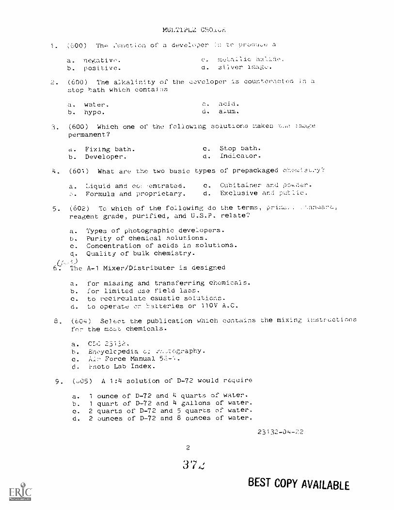
MULTIPLZ.
1. 600) The :unction of a developer to prociuee a
a.b.
negative.positive,
c. hallde.silver image.
2. (600) The alkalinity of the developer is counteracted instop bath which contaLls
a. water.b. hypo.
c. acid.d. alum.
3. (600) Which one of the following solutions makes v,,e imagepermanent?
a. Fixing bath. c. Stop nath.b. Developer. d. Indicator.
4. (601) What are the two basic types of prepackaged ehest:v?
a. 'Liquid and co:, .entrated. c. Cubitainer and por.Formula and proprietary. d. Exclusive an.:
5. (602) Tc which of the followinq do the terms,reagent grade, purified, and U.S.P. relate?
a. Types of photographic developers.b. Purity of chemical solutions.c. Concentration of acids in solutions.q. Quality of bulk chemistry.
6. The A-1 Mixer/Distributer is designed
a. for missing and transferring chemicals.b. for limited use field labs.c. to recirculate caustic solutions,d. to operate Cr b:,.Atteries or 110V A.C.
8. (604) Se3e:ct the publication which contains the mixing instructionsfor the mo:,,t chemicals.
a. CIA: 23132.b. Eneycicpedia clc. Force Manual 52-,d. i-noto Lab Index.
9. (005) A 1:4 solution of D-72 would require
a. 1 ounce ofh. 1 quart ofc. 2 quarts ofd. 2 ounces of
D-72 and 4 quarts of water.D-72 and 4 gallons of water.D-72 and 5 quarts of water.D-72 and 8 ounces of water.
2
23132-04-22
BEST COPY AVAILABLE
10. (606) Which of the followi:ig of i.
geaduates?
Thoy will not. ti
0. 01ns::7, is inct't Le most chemic.:11::.c. Calibration marks are easie :. to r,00.d. Glass graduates are marked in ounces and
ng
11. (607) Which of the rollowing pr:icLices is not c01:3istw,Air Forc environmental practices?
a. Dumping photo chemicals in large Jcpdie:; of water.b. Installation of treatment faciles.c. Insure contracts for disposal 02 w-istes meet loc;:.1d. Store and handle products in a manner that wiil riz
pollution.
12. (608) Which silver recovery method generates noxious
a. Chemical precipitation. 6. Incineration.b. Metallic replacement. d. Electrolytic.
(609) What are the two methoes of recovering silver :'om black-and-white film?
a. Precipitation and replacement.b. Shredding and electrolytic.c. Regeneration and smelting.d. Incineration and stripping.
14. (609) Select the correct 6tatemer' regarding the recovery ofsilver from film.
i. The stripping method is more expensive than incineration.b. Regeneration and smelting require xtremely high tempercitu!-el-;.c. Shredding is preferred for large volume lats.d. Precipitation recovery units may be usea in small labs.
15. (610) Small Individual weights should be handled with tongsor gloved hands to
a. ens,_:rz; accurate measurements.b. f-,revent ---nd scratching.c. ensure proper placement in c,he pan.d. prevent fingerprint corrosic.
16. (.1) Which of the following situations ,,oald require t e useof a fine grain negative developer?
a. Shooting high speed action photography.b. Copying highly reflective subjects.c. Producing enlargements from small negative.d. Making black-and-white prints from color negatives.
23132-04-22
3

(6'1) Film ahd cev on
a. the time reghi!'ements of the nshion.b. the size of the prints to be maUe.c. grain size characteristics or the paper.d. whether you use roll film or sheet fi.J.c%.
18. (612) Why is tank processing preferred for sheet
a. The:'e is less chance of temperaore vahiatiens.b. it can be done with the room .ights en.c. You can use a stronger light ih the szA(elighL.d. Results are more uniform for large numbers or sheets.
19. (D13) What color of safelight filter would best be suited foruse with panchromatic film?
a. Light red.b. Dark blue.
.
d.
Light yellow.Dark green.
20. (614) Which of the following is the proper method of placlngloaded film hangers into the developer?
Place each hanger in separately.b. Lower all of the hangers simultaneously.e. Stack the hangers from the bottom up.d. Alternate the hangers at 90° angles.
21. (614) Which processing solution does not require agitatLon?
a. Developer. c. Fixer.
b. Stop bath. d. Ivetting agent.
22. (615) Which of the following statements is true regarding theprocessing of roll film?
a. The film is attached to the ree: with the emulsion facinginward.
b. Roll film processj.ng is 'Pest accomplished by using trays.c. Sprocket holes must be trimmed off prior to processing.a. The film is soaked in wetting agent to remove the paper
backing.
23. (618) Temperai.ur:s of the processing solutions should be
a, mantained below 68° for all rilms.b, checked after you place the the developer.c, lowered if you have to process a large volume of film.d. held as near to each other as possible.
4
374
23132-04-22
24, (616) When the emulsion aubjeeted to excessive expansionand contraction it is said Ln oe
a. accelerated.b. reticulated.
C. intensified.d. emuisifieu.
(617) What will happen to a negative if the rim is n2t_agitated in the developer?
a. The shadows will be too dark.b. The middle tones will block up.c. The highlights will be underdeveloped.d. The contrast will be excessive.
26. (617) Film is agitated in a roll film tank by
a. vigorous rocking of the tank.b. releasing gas into the tank.c. turning the agitation rod.d. inverting the tank.
27. (618) Which type of film is best suited for making black-and-white positives?
a. Fine grain positive.b. Course Grain positive.c. Single-step positive.d. Commercial contrast positive.
28. (619) Select the equipment which is designed to improve theefficiency of tray washing?
a. IngestEr. c. Extractor.b. Siphon. d. Ladle.
29. (619) Which of the following is most likely to cauze your negativesto be stained?
a. Omitting the clearing bath.b. Using wash water that is too hot.c. Leavg film in film hangers to dry.d. Allowing byproducts to remain in the film.
30. (620) A solution should be used to break the surface tensionof water on the film in order to icvent
a. air bells.b. graininess.
5
c. water spots.d. stains.
3 70
23132-04-22
31. (621) Determine the cause i':)r c.0
a. Too much heat while the fLl_ wan oryLng.
b. Omitting the fixer step during processing.c. Opening the drying cabineL doors while the blower wa:;d. Dirt and scum in the wet.tIng sc.Laticn.
32. (622) What is the purpose of opaquing a black-and-white
a. Increase printing time.b. Eliminate pinholes and scratches.c. Reduce processing time.d. Add detail to the negative.
33. (623) List the factors considered when selecting negatives tobe printed.
a. Focus, format, contrast.b. Grain, exposure, size.
c. Identify, defecL,d. Speed, focus, grain.
34. (623) All negative selection factors must be based on ther
the final print will be
a. mounted. c. published.b. displayable. d. pleasing.
35. (624) Select the advaruage of using water based ink to letter
negatives.
a. It can be washed off if you make a mist:ake.b. You can use smaller tipped pens.c. Water based ink is available in more colors.d. It is transparent and can be used on the image area.
36. (625) What is the maximum relative humidity permL.ssabae in a
film storage area?
a. 10 pe:cc:nt.b. 25 percent.
c. ::;0 percent.d. 79 percent.
37. (626) Tho cLajo:-. pact of operator ma :Lenance in the processing.blvea with
a.
b. ;leanliness.
c. storage.
38. 027) Safety in the laboratol.;) elotr,cal equipmentto be
a. close to the operator.b. on the highest shelves. c. on the wet side.
23132-04-22
0
39. (628) What is the basic paper developer used in the Air For?
a. DK-19.b. DK-50.
c. D-62.d. D-72.
40. (629) Agitation of a print in the developer shod be
a. vigorous.b. stagnant.
c. constant.d. intermittent.
41. (630) The purpose of a stop bath is to
a. remove the antihalation backing.b. stop or slow down development.c. make the image permanent.d. prolong the life of the developer.
42. (630) What are the two basic types of stop bath?
a. Water and acid. c. Neutral and alkali.b. Dilute and chemical. d. Hardening and permanent.
43. (630) Which processing solution changes undeveloped silver intosoluble salts?
a. Stop bath. c. Hypo clearing bath.b. Fixing bath. d. Acid hardener bath.
44. (631) Select the correct statement regarding time and temperatureof processing solutions.
a. As time and temperature increase density decreases.b. As time and temperature decrease density increases.c. As time and temperature increase density increases.d. There is no correlation between time, temperature, and density.
45. (632) A lack of agitation in the developer may cause
a. mottle. c. high contrast.b. frilling. d. high density.
46. (632) Small, circular, clear spots on a print are caused by
a. air bubbles. c. hot developer.b. light leaks. d. vigorous agitation.
47. (633) Select the graded contast paper used to print a very flatnegative.
a. One.b. Two.
7
c. Three.d. Four.
37 /
23132-04-22
46. (634) Which of :.heof a print?
a. e,radea paper.U. 11,tehu t,me.c. Shorteh the u ve]opmcnt LLme.d. Use a print toner.
49. (635) Select the light color reqi:i :'a La achi ve hlt;a er,trawith variable contrast paper.
a. Yellow-green. c. hed-yeAlow.b. Blue-violet. d. Blue-green.
50. :636) Which of the folowing safeligit i'ilters should be usedwith variable contrast paper?
a. P. (red).b. Al (Drown).
c. OA (orange).d. OC (amber).
51. (637) In printing papers, to which of the following eees theterm "surace" refer'?
5-)
Tint and tone.b. Finish and texture.
c. Tint and textue.d. Tone and finish.
(638) A print that is to be rprodueed in a newspaper shouldbe printed on
a. matte paper.b. semimatte paper.
a. low luster paper.d. glossy paper.
53. (639) The tone of a print depends primarily upon
a. exposure and dodging.b. paper and developer coml)i;-1att.c. contrast and cea_l.d. the neative the .-e2;'oductir:,s.
0:)37.i) Wniah 02 1Yr.e rlo,c a pr.hz_ to reproduce the\alues of : scene.
a.6. A flat
In order tc, eontrclof the following must
e. Too much deail.d. Too litt-de
Graded develop. c.6. Diffused lignt.
8
c. Test strips.
23132-04-2;?
pa2e
56. (641) The negative and paper are held together in a contactprinter by the
a. mask.b. platen.
c. filter roll.d. diffusion glass.
57. (641) Uniform iliumination is maintained on a contact printerby using a
a. platen. c. filter wheel.b. argon lamps. d. diffusion glass.
58. (642) Which of the followng can be ppoduced by using a contactprinter?
a. Proof sheet. c. Enlargements.b. 2 to 1 image. d. Reductions.
59. (643) Select the projection printer which will produce the maximumamount of detail in the print.
a. Condenser. c. Pneumatic.b. Diffusion. d. Mechanical.
60. (644) Which of the following lists contains components applicableonly to the EN-52B projection printer?
a. Argon lamps, filter wheel, and condenser.b. Lamphouse, lens, cone, and platen.c. Baseboard, lens, and diffusion glass.d. Negative carrier, lens cone, and condenser.
61. (645) What must be changed to obtain sharp focus while projectionprinting?
a. Lens-to-film distance.b. Negative carrier size.c. Cam follower wheel ratio.d. Focal diameter pf the lens.
62. (646) An easel is used to form a border and to
a. produce print texture.b. hold the paper flat.c. reduce paper waste.d. eliminate -.3.ust from the negative.
63. (646) Which one of the following is used to produce white bcrderson contact prints?
a. Frisket.b. Pallet.
9
c. Mask.d. Easel.
3 7 d
23132-04-22
64. (647) shou,c h
. In the i:pporIn a posit-:,
C. With ttle .7. upd. Wlth the st-ic
b5. (648) Which of ti-c ; t!,2 proper ::,rocciure
exposing a test
a. Expose each stri,p at the same exp,)sure.b. Each strip should coale from a differen aegLtAve area.c. Each strip should contain ',he same parts of the naa,.ive.6. Expose each strip at ifCat. degi.ee of ehlarement.
66. (649) Select the procedure used to dodge an area of a contactprint.
a. Change filters.b. Use a tranAr:.:nt mask.c. Increase rhe c,xposure time.d. Manipulate individual priter lamps.
67. ,:;9) Why is burning-in used in pcojection printin?
a. To increase loca, density.b. To increase ovtirall density.c. To decrease local contrast.d. To increase overall contrast.
68. (650) Select the required proccCure ',,hen composing a projectionprint and desirng a bigger imr:Ige.
a. Use a longer focal length lens.b. Move the printer head farther from theo. Moie the lan6 cloc.:n to thed. Chans: to a 1:iL-ger
(651.or.htrol ean be
b.
d. ana s.ase;
70 , Which of the followan:i .,.,,:Ary to ir.aKe a
Masking .-rojectIoa
Master positive. d. Argon lamps.
10
231=52-04-22
BEST COPY AVAILABLE
71. (653) How should unexposed paper be stored?
a. On end.b. Flat.
c. Near the processing room.d. At a humidity over 70 perct;IL.
72. (654) If a negative carrier has burns, what should be done?
a. Throw it away. c. Tag it for maintenance.b. Turn it inside out. d. File or sand them smooth.
73. (655) Which of the following lists contains factors applicableonly to print washing time?
a. Exhaust3d fixer, type of paper, and water exchange rate.b. Agitation, weight of paper, and length of exposure.c. Use of hypo clearing ag.nt, method of washing, and pH of stop
bath.d. Temperature of water, weight of paper, and time of day.
74 (656) The Pakolux should be loaded with prints one at a timeto
a. insure proper count.b. have each print go into its own slot.c. prevent sticking together.d. have sufficient drain time.
75. (657) Prints are treated in a predrying bath of glycerin, becaus.:this process
a. makes prints easier to mount.b. reduces curling tendencies.c. speeds removal of hypo.d. hardens the emulsion.
76. (657) What is the usual cause of cracks in dry print:.)?
a. Too much glycerin in the softening bath.b. Too little hardener in the fixer.c. Rough handling of the prints.d. Excessive humidity in the storage room.
77. (658) The sliding cover of the Pako Tempro 400 dryer shouldbe opened to
a. vent excess humidity.b. reduce drying time.
11
c. hut down the dryer.d. override the thermostat.
23132-04-22
78. (65)) Wh7At typ,. e. wuu, uebest suited for?
a. Large hurd--)-handie printa.b. Small j,:.egelarly shaped prints.c. Prints to 1)e displayed fdr .
d. Pr:,nts wh.ieh need 1.o 1,e .;,1dILd for
79. ((60) After mountin a prtnt, bebackward away .-rom the print c.o
a. speed up eoeln; Lime .b. check for per'mancht adhcson.e. dheck for air Imbl-.1es.d. make the prnt flat.
Cd. (660) What will happen if toe much heat ia appl te0 while moudtH-q:;-p print?
a. The mount pre3F. therLuodtat will shut off the pre_.b. The wi1 cJlip uut of p-,nce in thec. The moarlt:r. wil me:c absorb i.nto thC. The cover sheet wtli at)scro !:hd exdes,u heat.
81. -)(1) Which f hc. r'oi&ac., a the easiest methiwritten ;,-,Cor77,!.:Lon a permi:hent purL, of the ;,,ridt?
a. Typimz.D. Attaching
liand
C. Ink st.inpin.
662) Select the eoudLtion which would cause poc mark:::: on a
dried on a doum dryer.
Dirt on the a;-)rph.Improfc.er tr.I n adjus,tmen,-,.
c. pclleru.d. ,-ieratenen on Lh drum.
radiatir,:-; at iCj dm.
Hue.
84. 66 ,) ,_11.pw:,; a materli to absort:, radiation dtone wa:eledgth ;.1: another wave'len,:qh.
-:terferen,e.refraction.
3 S )
,conee.
2312-04-22
BEST COPY AVAILABLE
85. (663) What is the term used to descr.Loe a certain color of asubject?
a. Hue. c. Purity.b. Brilliance. d. Saturation.
86. (664) What two colors of light will combine to make yellow?
a. Magenta and cyan. C. Green and magenta.b. Green and red. d. Blue and red.
87. (665) Select the color of light which a cyan filter will absorb.
a. Red.b. Green.
c. Blue.d. Cyan.
88. (666) What color of light will the middle layer of color filmrecord?
a. Red.
b. Yellow.c. Blue.d. Green.
89. (366) Daylight color film is extra sensitive to which colorof light?
a. Red.b. Blue.
c. Magenta.d. Yellow.
90. (666) Which of the following is required to use tungsten filmin daylight?
a. Increase exposure.b. Increase development time.c. Use appropriate conversion filter.d. Use blue filtered light source.
91. (667) Select the proper temperature in the storage area whenstoring color film longer than 6 months.
a. 550 to 75°F. c. 25° to 35°F.b. 45° to 65°F. d. 0° to -10°F.
92. (667) Which of the following storage conditions is most likelyto cause dye changes in color film?
a. High temperature. c. L.ow temperature.b. high humidity. d. Low humidity.
13
3 j
23132-04-22
93- (068)
a. A color o,hi reo.
b. A color r.hi Lowardc. Higly cdlor.d. WruAled aut
(669) Se_ect. 1.1c al
tungsten light.
a. Compensating. d. balaalhc.b. Conversion. d. Special.
95. 670) Which of the Col ,A,;In ,f t cp
duplicating camera?
a. Quartz I ph.,..':a. Cirouadasapae.;,y.
9 . (.671) To cop:: t ;:nderexpc,ser!.
must be made rro no;-.:4(1 e;:po;:ure?
Gpon up !.11....)3c (-Iowa or..
Open up tvro CLopC. a. Ciose down two
97. 072) Whi(Ch 1.;..c:) procuae:_.
niiver image?
b.
cavelo-per.Reversal n6th.
develepec.Cond-itionkir.
96. (.:,73) What is ttp:: :_rage 1-..mo for used
b. 3
c. 1,:ccks.
d.
a. hoi, severa:,
-
.
reveral
.,30 to 20°C.Lo d. to 96T.
384 BEST COPY AVAILABLE
101. (676) Select the correct statement regarding a plastic withglass slide mounts.
a. They have superb impact resis6ance.b. They are cheaper than metal with glass mounts.d. Newton Rings are not a problem with plastic and s:lass mouts.d. Waterproof tape must be used with plastic and glass mount.
102. (676) What is the principal disadvantage of glassless sl aemounts?
a. Loss of protection. c. Prohibitive cost.
b. Newton ring formation. d. Unadaptable to equipment.
103. (677) What is needed to seal carboard mounts?
a. Glue and pressure. c. Heat and pressure.
b. Tape and pressure. d. Tape and heat.
104. (678) In which of the following rooms would it beto have a chemical-free environment?
a. Projection printing.b. Finishing.
e-d.
Film loading.Storage.
most dc-.:-;irable
105. (678) At what point do negatives require the least amount ofprotection?
a. During down loading. c. While hanging up to dry.
b. After they are dry. d. Just before processing.
106. (679) Select the correct procedure to prevent the formationof small, irregularly shaped transparent spots en your ne:ratives.
a. Use of a tripod during exposure.b. Increase initial agitation in the developer.c. Lower the processing temperatures.d. Clean the interior of the camera.
107. (679) improper agitation of a print in the acid stop bath willcause
a. blisters. c. purple discolorations.b. reticulatio:,. d. grayish mottle.
108. (6E0) What is the science of atne affects of exposureand processing on photographic materials?
Sensitometry. c. Photo chc,mistr_...
n. Densitometry. d. Variability.
15
3 '5 a
23132-04-22

t.)
BEST COPY AVAILABLE
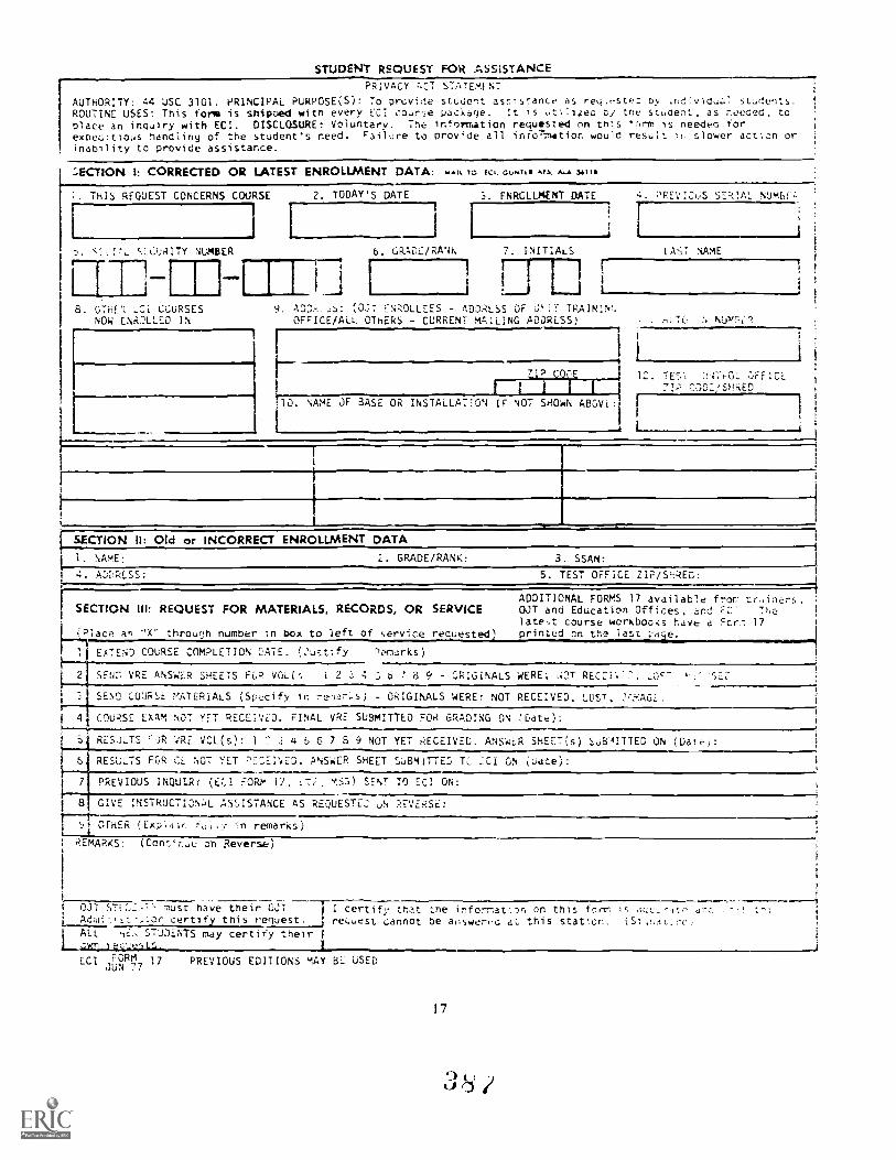
STUDENT REQUEST FOR ASSISTANCEPRIVACY ACT STATEMENT
AUTHORITY: 44 USC 3101. PRINCIPAL PURPOSE(S): To prcvide student assistance as reu.,stm.:: oy stLdents.ROUTINE USES: This form is shipoed witn every ECI co..rse package. It is .:Alicec by tne stAent, as noeoeo, toplace an inquiry with EC1. DISCLOSURE: Voluntary. The information requesteol on this 1.rm is needen forexpeuitious handling of the student's need. Failure to provide all ihro7mat1on would result 1:. slower acti.Dn orinability to provide assistance.
3ECTION I: CORRECTED OR LATEST ENROLLMENT DATA: MAIL 70 EC,. 01.$4,47ri ALA Ulla
1. THIS REQUEST CONCERNS COURSE 2. TODAY'S DATE S. ENROLLMENT DATE 4. PREVIOUS SEMAL NUMBF.,
1 ...I
r
---...1
si:;_ Si.CURITY NUMBER 6. GRADE/RANK 7. INITIALS LAST XAME
,- I1
i rEi ! ,
i ;1 :....--1 11
8. GTHEI 1_Ci CCURSES 9. ADDS..S: (0j7 ENROLLEES DDRLSS OF GIT TRAININt.NOW ENRaLED IN OFFICE/ALL OTHERS - CURRENT MAILING ADDRESS) ,:uTC :. NIJY730.
1 i4
Z19 C_OE 1 12. TEST Tjr471-O2 ciFICE 1
1
liiiii ?IR: 0303/SHRED 1
:10. NAME OF BASE OR INSTALLATION IF NOT SHOWN ABOVE:
I
I1
I
,_
SECTION H: (Did or INCORRECT ENROLLMENT DATA1. NAME: 2. GRADE/RANK: 3. SSAN:
4. AI-)I,PESS: 5. TEST OFFICE ZIP/SRED:
ADDITIONAL FORYS 17 available fror. ::,c,inens.SECTION HI: REC)UEST FC)R MATERIALS, RECC)RDS, C)R SERVICE OJT and Education Offices, and EC: The
latest course workbooks have a Fcri 17;Place an "X" throucih number in box to left of service res'ested) .rinted on the Iasi: -a-e.
1 EXTEND COURSE COMPLETION DATE. (2ustify Demarks)
2 SEN5 VRE ANSWER SHEETS FCR VOL(s 1 2 3 4 3 5 ! 8 9 ORIGINALS WERE; ,:DT RECOI' 7. L05 . SEO
3. SEND LUURSE MATERIALS (Specify in rem.Irs) - ORIGINALS WERE: NOT RECEIVED, LOST, 7tRAGL.t
4 COURSE EXAM NOT YET RECEIVED. FINAL VRE SUBMITTED FOR GRADING ON C:ate):1
S RESULTS TA VRE VCL(s): 1 7 3 4 5 6 7 8 9 NOT YET RECEIVED. ANSWER SHE[T(s) SoEs'AITTED ON (Date): 1
6 RESULTS FOR CL NOT YET P:ZEI'4E.O. ANSWER SHEET SUBMITTED TC. CCI ON L.Jate):
7 PREVIOUS INQULRY (U.1 FORM 13, -,-..:. MSS) SENT TO ECI ON:
8 GIVE INSTRUCTIONL ASSISTANCE AS REQUESTEU UN REVERSE: ,
nri-ica (Fxrr ',.. in ramar'w,1
REMARKS: (Cent'r.uu o'n Reverse)
OCT S. I.Z7 must have their OJTor certify this request.
1 ALL , iE. STUDENTS may certify their I
ECI FORM 17JUN 77
I certify that tne informaton on this fnrmrequest cannot be abswerc-c at this station.
Is ,IcCL--iu,
PREVIOUS EDITIONS MAY BE USED
1 7
I I/
SEC.1tC,N 4V: ,-; C.
Nc.
;
BEST COPY AVAILABLE
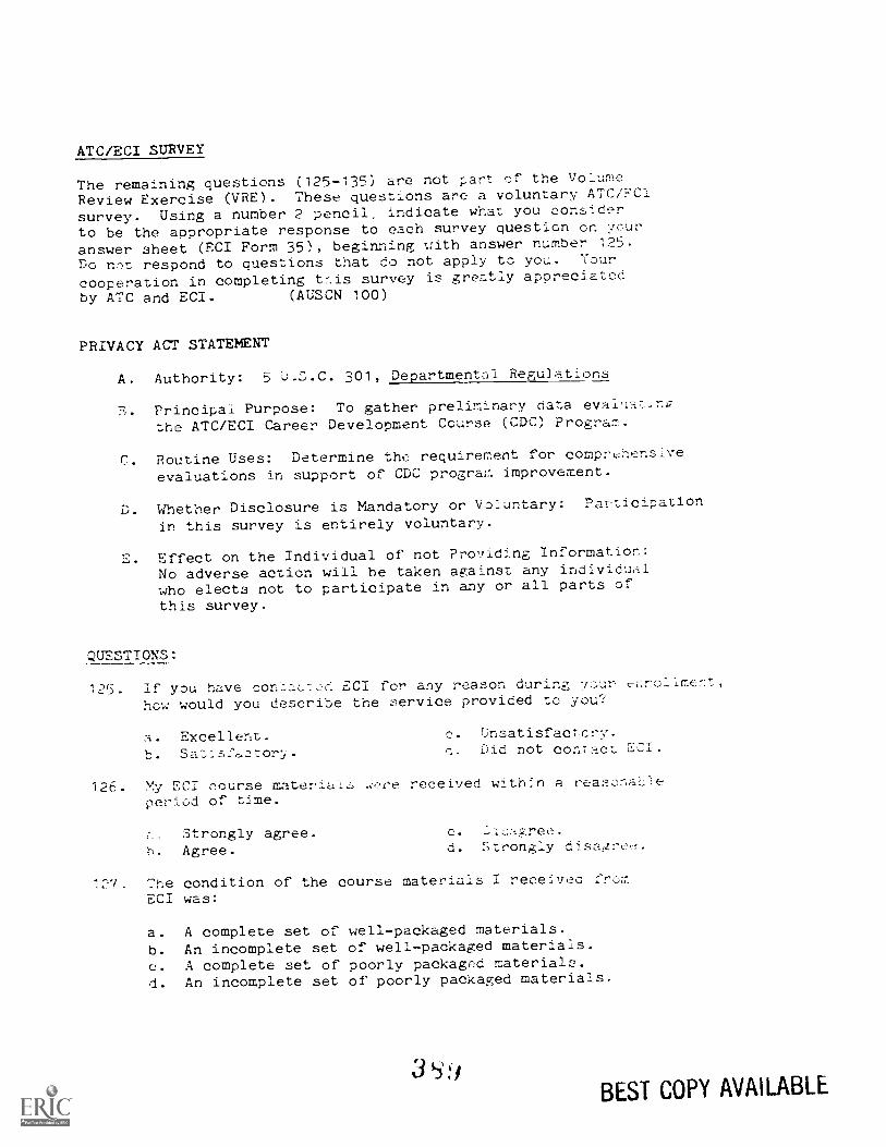
ATC/ECI SURVEY
The remaining questions (125-135) are not c-art of the Volume
Review Exercise (VRE). These questions are a voluntary ATC/FCI
survey. Using a number 2 pencil, indicate what you consider
to be the appropriate response to each survey question ch yc.ur
answer sheet (ECI Form 35), beginning with answer number 125.Do nct respond to questions that do not apply to you. Your
cooperation in completing t:tis survey is greatly appreciatcd
by ATC and ECI. (AUSCN 100)
PRIVACY ACT STATEMENT
A. Authority: 5 Li.S.C. 301, Departmental Regu]ations
S. Principal Purpose: To gather preliminary data eval,:athe ATC/ECI Career Development Course (CDC) Program.
C. Routine Uses: Determine the requirement for comprehensiveevaluations in support of CDC program improvement.
D. Whether Disclosure is Mandatory or Voluntary: Participation
in this survey is entirely voluntary.
E. Effect on the Individual of not Prcy!iding Information:No adverse action will he taken against any individulwho elects not to participate in any or all parts of
this survey.
.WESTIONS:
125. If you have con:La...c: ECI for any reason during vc-,ur ec.rollmer.t,
how would you describe the service provided to you?
a. Excellent. 0. Unsatisfactcry.
b. Sa'Lfs:ctor:i'. C. Did not contct 551.
126. My ECI course material.L, .re received withn a reasonaieperiod of time.
,. Strongly agree.6. Agree.
C.
d. Strongly disai4re,-,..
17. The condition of the course materials I receiveo from
ECI was:
a. A complete set of well-packaged materials.b. An incomplete set of well-packaged materials.
c. A complete set of poorly packaged materials.d. An incomplete set of poorly packaged materials.
355,41
BEST COPY AVAILABLE
'?
3.;BEST COPY AVAILABLE
Related Documents