Description of the Opto- mechanical Design for the PFC Project name WEAVE Release Final: Version 1.1 Date: 06 July 2013 Author(s): Kevin Dee Owner: Don Carlos Abrams Client: WEAVE Consortium Document Number: WEAVE-PRI-017 To maximise the communities' access to information specific to the project, it is the policy of the project that documentation should be shared and made freely available to all stakeholders. While fully exploiting the dissemination of WEAVE information, the Project Management Team will ensure that the integrity and trust that are expected between the stakeholders are maintained. Please do not distribute this document outside the WEAVE Project Team without the permission of the WEAVE Project Office.

Welcome message from author
This document is posted to help you gain knowledge. Please leave a comment to let me know what you think about it! Share it to your friends and learn new things together.
Transcript

Description of the Opto-
mechanical Design for the PFC
Project name WEAVE
Release Final: Version 1.1
Date: 06 July 2013
Author(s):
Kevin Dee
Owner:
Don Carlos Abrams
Client:
WEAVE Consortium
Document Number:
WEAVE-PRI-017
To maximise the communities' access to information specific to the
project, it is the policy of the project that documentation should be
shared and made freely available to all stakeholders. While fully
exploiting the dissemination of WEAVE information, the Project
Management Team will ensure that the integrity and trust that are
expected between the stakeholders are maintained. Please do not
distribute this document outside the WEAVE Project Team without
the permission of the WEAVE Project Office.

PFC Opto-mechanical Design Date: 06-Jul-2013
WEAVE-PRI-017: Version 1.10 Page 2 of 35
Document History
Document
Location
Printed on Tuesday, 14 October 2014.
The document can be found at :
http://bscw.ing.iac.es/bscw/bscw.cgi/196211
Revision
History
Revision
date
Version Summary of Changes Changes
marked
18/06/2013 0.10 Document created by Kevin Dee Dee
25/06/13 1.00 Document released Abrams
06/07/13 1.1 180 to change to 130 in tables 5 and 6. 65 deg
zenith angle added fig 23 and 24
Dee
Approvals This document requires the following approvals.
Name Title Approval Date Issue Date Version
Gavin Dalton Principal Investigator
Don Carlos Abrams Project Manager
Kevin Dee System Manager
Distribution This document has been distributed to:
Name Title Issue Date Version
Gavin Dalton Principal Investigator 18-06-13 0.10
Tibor Agócs Optical Engineer 18-06-13 0.10
Don Carlos Abrams Project Manager 18-06-13 0.10
Emilie LHome Optical Engineer 18-06-13 0.10
Johan Pragt System Manager 18-06-13 0.10
Kevin Dee System Manager 18-06-13 0.10

PFC Opto-mechanical Design Date: 06-Jul-2013
WEAVE-PRI-017: Version 1.10 Page 3 of 35
TABLE OF CONTENTS
1 INTRODUCTION 5 1.1 Abbreviations 5 1.2 Purpose 5 1.3 Scope 5
1.4 Documents 5 1.4.1 Applicable Documents 5 1.4.2 Referenced Documents 5
2 OVERVIEW 6
3 WHT TRUSSES 6
4 WEAVE RING TO TELESCOPE TOP END 10
5 PFC CENTRAL CAN WITH VANES 12 5.1 Boundary conditions 13
6 LENS 1 CELL AND STRUCTURE TO CENTRAL CAN PRIME FOCUS
INTERFACE 14
7 SUMMARY OF ERROR BUDGET M1 /TO TOP-END UP TO PFC
INTERFACE 17
8 ANALYSIS AND DESCRIPTION OF LENS 1 AND ITS MOUNTING
CELL 17 8.1 Introduction 17
8.2 Original Lens Mount Design 18 8.3 Original Lens Cell 18 8.4 Improved Design for Lens Cell 1 19
8.5 Lens 1 with Constraints Applied to Mounting Pads 20 8.5.1 Results for Lens 1 with pads constrained (no cell included) 21
8.6 Lens 1 and its Cell 23
9 ANALYSIS OF THE EFFECTS OF CHANGING THE SETUP OF THE
RTV PADS 25
10 FEA ANALYSIS OF STRESSESS IN LENS 1 AND ITS CELL 25
11 SUMMARY OF FEA DATA ON LENS 1 AND CELL 26
Figure 1 - Boundary conditions analysis of WHT trusses. ........................................................ 7 Figure 2 - The FARO Vantage Laser Tracker mounted on the telescope cube along with the
laser targets (yellow) for distance measurements. ..................................................................... 8 Figure 3 - With no split collars on the trusses a differential decentre of 95 microns is evident
between the top and bottom ends of the telescope. .................................................................... 9 Figure 4 - Split collars are used to stiffen a truss. ...................................................................... 9
Figure 5 - With split collars fitted to the top trusses, there is a differential decentre of 20
microns between the top and bottom ends of the telescope. .................................................... 10 Figure 6 - Blade spring translation general layout for the WEAVE ring. ................................ 11 Figure 7 - Preliminary FEA of blade spring arrangement indicates a 55µ decentre due to
gravity at the horizon. ............................................................................................................... 11 Figure 8 - Vanes and Central Can. Loaded with PFC, Rotator and Fibre positioner. .............. 12

PFC Opto-mechanical Design Date: 06-Jul-2013
WEAVE-PRI-017: Version 1.10 Page 4 of 35
Figure 9 - At a zenith distance of 65 degrees, the interface between the PFC and the Central
Can exhibits a 100-micron decentre. ........................................................................................ 13 Figure 10 - Decentre with preloaded vanes. ............................................................................. 13 Figure 11 - Lens 1 Cell and extension interfaced to the Central Can. ..................................... 14
Figure 12 - FEA of Lens Cell 1 and its extension tube when at zenith. The three mounting
points are clearly identified as points of minimal displacement. ............................................. 15 Figure 13 - FEA of Lens Cell 1 and its extension tube @ 65 degrees from zenith.................. 15 Figure 14 - FEA of Lens Cell 1 and its extension tube @ 65 degrees from zenith.................. 16 Figure 15 - Lens 1 general dimensions and CoG. .................................................................... 18
Figure 16 - Lens 1 and the original lens cell mounting arrangement ....................................... 18 Figure 17 - Lens surface deformations using the original cell mounting arrangement. ........... 19
Figure 18 - Schematic representations of the lens cell mounting arrangements used in the
DECam (top) and MMT (bottom) designs. .............................................................................. 20 Figure 19 - Lens 1 in the revised lens cell. ............................................................................... 20 Figure 20 - Boundary Conditions for Lens 1 ........................................................................... 21 Figure 21 - Lens L1 surface 1 deformation at zenith was 302.33nm. ...................................... 21
Figure 22- Lens L1 surface 2 deformation at zenith was 249.896nm. ..................................... 22 Figure 23 - Lens L1 surface 1 deformation at zenith was 155.82nm. ...................................... 22 Figure 24 - Lens L1 Surface 2 deformation at zenith was 136.25nm. ..................................... 23 Figure 25 - Overall displacement values for L1 and its cell when the telescope is pointing at
zenith. ....................................................................................................................................... 23 Figure 26 - Lens 1 and its cell at 65 degrees ............................................................................ 24
Figure 27 - The tilt due to the RTV pads at 65 degrees zenith distance (left) and the
exaggerated deformation of the RTV pads (right). .................................................................. 25
Figure 28 - Stress analysis on the lens (left) and cell (right) when at zenith. .......................... 25 Figure 29 - Stress analysis on the lens (left) and cell (right) when at 65 degrees zenith
distance. .................................................................................................................................... 26 Figure 30 - General lens layout with Lens 2 highlighted. ........................................................ 28 Figure 31 - The PFC middle section (for ADC) and end section (for Lens 6) housings ......... 28
Figure 32 - Lens 2 in lens cell. ................................................................................................. 29 Figure 33 - FEA of lens when mounted in its cell at 65 degrees zenith distance. ................... 29
Figure 34 - FEA of lens when mounted in its cell at zenith. .................................................... 30

PFC Opto-mechanical Design Date: 06-Jul-2013
WEAVE-PRI-017: Version 1.10 Page 5 of 35
1 INTRODUCTION
WEAVE is a new wide-field spectroscopy facility proposed for the prime focus of the 4.2m
William Herschel Telescope. The facility comprises a new 2 degree field of view prime focus
corrector with a 1000-multiplex fibre positioner, a small number of individually deployable
integral field units, and a large single integral field unit. The IFUs and the MOS fibres can be
used to feed a dual-beam spectrograph that will provide full coverage of the majority of the
visible spectrum in a single exposure at a spectral resolution of ~5000 or modest wavelength
coverage in both arms at a resolution ~20000. The instrument is expected to be on-sky by
2017 to provide spectroscopic sampling of the fainter end of the GAIA astrometric catalogue,
chemical labelling of stars to V~17, and dedicated follow up of substantial numbers of
sources from the medium deep LOFAR surveys.
1.1 Abbreviations
The abbreviations and acronyms used in this document can be found in WEAVE-MAN-001.
1.2 Purpose
The purpose of this document is to describe the opto-mechanical aspects associated with the
mounting of the WEAVE prime focus corrector (PFC) optics with respect to the telescope
primary mirror (M1).
1.3 Scope
The document presents the results of the analyses of the structures supporting the PFC with
respect to M1. It also looks at the detail mounting arrangement of lens 1 within its cell.
1.4 Documents
1.4.1 Applicable Documents
Document Identifier Document Title
WEAVE-MAN-001 Abbreviations and Definitions
WEAVE-SCI-001 Science Requirements Document
WEAVE-SYS-001 Instrument Development Specification Document
1.4.2 Referenced Documents
Document Identifier Document Title
WEAVE Top End 12006-
900001
WEAVE PROJECT
FEA Services for Top End Ring
Assembly and Focus Can/Centre
Section
Laser tracker Spie 2012-
8444-196.pdf
Using a laser tracker for active alignment on the
Large Binocular Telescope PFC_design_corrector_housing
OCA June 2013.pdf Corrector Housing
WEAVE_report_I.ppt FEM analysis of Lens 1. Report 1
WEAVE_report_II.ppt FEM analysis of Lens 1. Report 2
WEAVE_report_III.ppt FEM analysis of Lens 1. Report 3
WEAVE_report_IV.ppt FEM analysis of Lens 1. Report 4
2009 Blanco DECam design
alignment.pdf
The design and alignment of the DECam lenses
and modelling of the static shear pattern and its
impact on weak lensing measurements

PFC Opto-mechanical Design Date: 06-Jul-2013
WEAVE-PRI-017: Version 1.10 Page 6 of 35
CFA Harvard design of cell
mount.pdf
Design of a cell for the wide-field corrector for
the converted MMT
CFA Harvard mounting large
lens MMT.pdf
Mounting large lenses in wide-field instruments
for the converted MMT
13001-900001 FEA for
corrector Lens 1 and cell.pdf
WEAVE PROJECT FEA Services for Corrector
Lens Mounts.
2 OVERVIEW
The optics for the WEAVE prime focus corrector are in the process of a final design review.
The mechanical designs presented for the lens mounts and supporting structures shall
sufficiently demonstrate that the PFC remains within decentration, tilt, and axial spacing
budgets and that induced stresses, and lens surface deformations are tolerable. A level of
design detail is expected which can justify that the designs are understood and although final
opto-mechancal designs are not offered they infer a route to final design that does not
preclude purchasing the optical blanks.
FEA was used to ascertain if the flexure of the WEAVE top-end meets the specifications for
decentre and tilt. If a specification was not met details of the subsequent work required is
described in order to achieve compliance.
Lens 1 is a large lens and more detailed analysis of mounting it in its cell is explored to
demonstrate that the current design is feasible and can ultimately be taken to a final design.
The scope of this report does not include detail descriptions of mechanical systems unless
they have direct influence on procurement of lens blanks.
3 WHT TRUSSES
The performance of the telescope trusses has, to date, been analysed using the Finite Element
Method (FEM). The overall flexure as a function of elevation of the primary mirror (M1)
assembly with respect to the top-end assembly was analysed to derive how much of the error
budget was attributed to the telescope trusses.
The tests were conducted from zenith to the astronomical horizon (90 degrees) but the results
were narrowed to look at a 60 degree range from zenith with 30 degrees zenith distance being
the mean position. The actual observing range requirement for maintaining the optical quality
is zenith to 60 degrees zenith distance (IDS-806).

PFC Opto-mechanical Design Date: 06-Jul-2013
WEAVE-PRI-017: Version 1.10 Page 7 of 35
Figure 1 - Boundary conditions analysis of WHT trusses.
Figure 1 illustrates the boundary conditions that were applied during the FEM analysis. The
telescope is balanced about the altitude axis i.e. as mass and moments are altered at the top-
end of the telescope, the mass is altered at the M1 bottom end to keep the CoG acting through
the altitude rotation axis. Note number highlighted in red are carried forward to table 8
Mean
Angle (degrees). 90 80 70 60 50 40 30
Decentre Lower Truss mm 0.04 0.16 0.29 0.50 0.60 0.78 0.88
Decentre Upper Truss mm 0.01 0.08 0.15 0.22 0.28 0.33 0.37
Net Decentre mm 0.03 0.09 0.15 0.28 0.33 0.45 0.51
FEA Net decentre from mean. Microns 250µ 190µ 130µ 0 -50µ -170µ -230µ
Tilt Lower Truss to Upper truss
-
0.0002 0 0.0003 0.0004 0.0006 0.0007 0.0008
Table 1- Decentre of Telescope Trusses
Top End Displacement/tilt Neg Pos Total Comments
Axial displacement (microns) 10µ 10µ 20µ Focus translation of top end
Decentre x (microns) 25µ 25µ 50µ ALT/AZ not considered an issue
Decentre y (microns) 200µ 200µ 400µ Main component of decentre
Tilt x (degrees) -0.0007 0.0007 0.0014 ALT/AZ not considered an issue
Tilt y (degrees) -0.003 0.003 0.006 Active tilt compensation 0.001 deg
Table 2 - WEAVE optical corrector error budget for M1 to Lens 1 in the PFC. These values were
extracted from the Excel spread sheet (Appendix A).
PFC Opto-mechanical Design Date: 06-Jul-2013
WEAVE-PRI-017: Version 1.10 Page 8 of 35
The FEM of analysis alone is not sufficient to conclude the actual performance of the trusses
and considering that the current performance of M1 to the secondary performs well, it tends to
infer that there is a possibility that the truss FEA analysis does not reflect the actual case. It is
therefore essential that detailed measurements are taken.
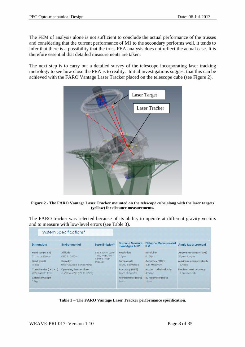
The next step is to carry out a detailed survey of the telescope incorporating laser tracking
metrology to see how close the FEA is to reality. Initial investigations suggest that this can be
achieved with the FARO Vantage Laser Tracker placed on the telescope cube (see Figure 2).
Figure 2 - The FARO Vantage Laser Tracker mounted on the telescope cube along with the laser targets
(yellow) for distance measurements.
The FARO tracker was selected because of its ability to operate at different gravity vectors
and to measure with low-level errors (see Table 3).
Table 3 – The FARO Vantage Laser Tracker performance specification.
Laser Tracker
Laser Target

PFC Opto-mechanical Design Date: 06-Jul-2013
WEAVE-PRI-017: Version 1.10 Page 9 of 35
Below is an extract from “Using a laser tracker for active alignment on the Large Binocular
Telescope” (Rakich et al. (2012), SPIE):
“Experience with the tracker at LBT, has shown that the laser tracker is capable of measuring optical
component positions during telescope use with accuracies of the order of 20 microns RMS. Obviously if the laser
tracker could be used to routinely position optics to this degree of accuracy, large positioning errors arising
from large structural gradients would be effectively eliminated, and the problems arising from optics positioning
uncertainties caused by the degeneracy of coma-corrected optics positions would be mostly mitigated”.
Some thought has already been given to improving the decentre values if the actual decentre
of the trusses is greater than the portion of the error budget allocated. However, because the
current M1 to secondary performance is acceptable it is thought that such an improvement
will not be required. Nevertheless, the solution is to fine tune the differential flexure by
stiffening the trusses with a split collar. This has been analysed and the results are promising
as shown in Figures 3 to 5 where the differential decentre is reduced from 95 to 20 microns
Figure 3 - With no split collars on the trusses a differential decentre of 95 microns is evident between the
top and bottom ends of the telescope.
Figure 4 - Split collars are used to stiffen a truss.
PFC Opto-mechanical Design Date: 06-Jul-2013
WEAVE-PRI-017: Version 1.10 Page 10 of 35
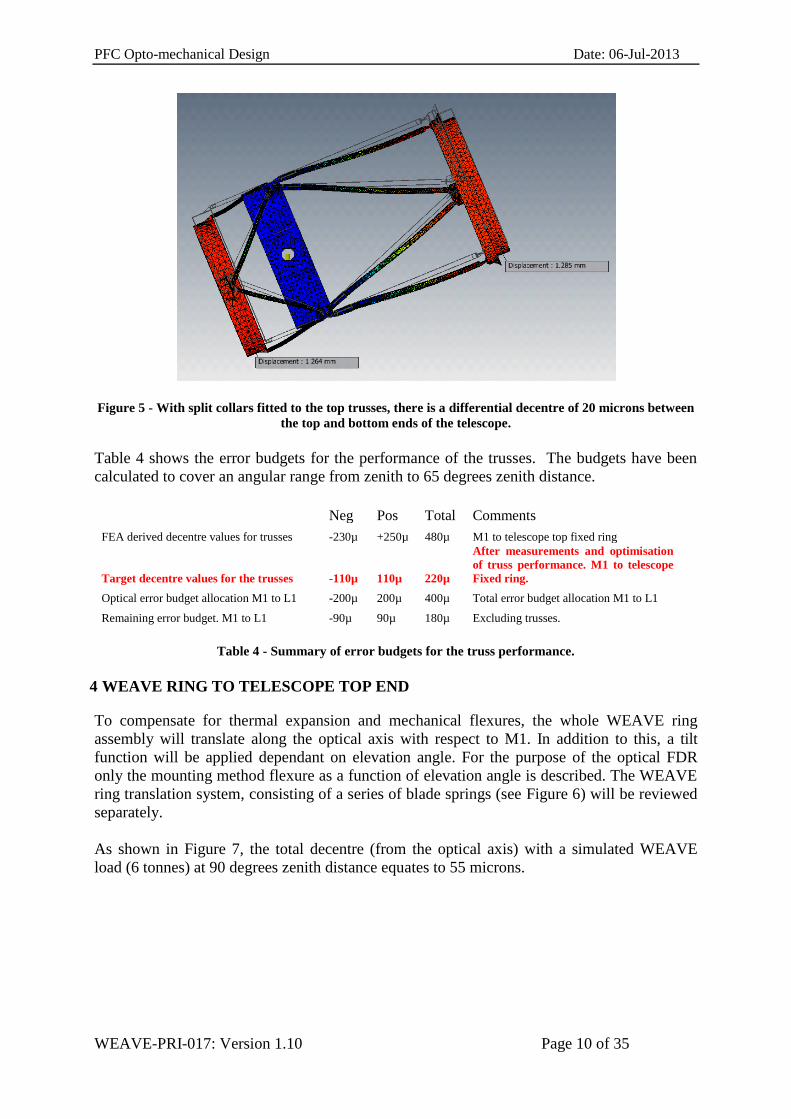
Figure 5 - With split collars fitted to the top trusses, there is a differential decentre of 20 microns between
the top and bottom ends of the telescope.
Table 4 shows the error budgets for the performance of the trusses. The budgets have been
calculated to cover an angular range from zenith to 65 degrees zenith distance.
Neg Pos Total Comments
FEA derived decentre values for trusses -230µ +250µ 480µ M1 to telescope top fixed ring
Target decentre values for the trusses -110µ 110µ 220µ
After measurements and optimisation
of truss performance. M1 to telescope
Fixed ring.
Optical error budget allocation M1 to L1 -200µ 200µ 400µ Total error budget allocation M1 to L1
Remaining error budget. M1 to L1 -90µ 90µ 180µ Excluding trusses.
Table 4 - Summary of error budgets for the truss performance.
4 WEAVE RING TO TELESCOPE TOP END
To compensate for thermal expansion and mechanical flexures, the whole WEAVE ring
assembly will translate along the optical axis with respect to M1. In addition to this, a tilt
function will be applied dependant on elevation angle. For the purpose of the optical FDR
only the mounting method flexure as a function of elevation angle is described. The WEAVE
ring translation system, consisting of a series of blade springs (see Figure 6) will be reviewed
separately.
As shown in Figure 7, the total decentre (from the optical axis) with a simulated WEAVE
load (6 tonnes) at 90 degrees zenith distance equates to 55 microns.

PFC Opto-mechanical Design Date: 06-Jul-2013
WEAVE-PRI-017: Version 1.10 Page 11 of 35
Figure 6 - Blade spring translation general layout for the WEAVE ring.
Figure 7 - Preliminary FEA of blade spring arrangement indicates a 55µ decentre due to gravity at the
horizon.
Neg Pos Total Comments FEA derived decentre values for Blade
Springs. -20 +20 40µ
55µ over 90 degrees. Assume 40 microns
over 65 degrees.
Remaining error budget. M1 to L1 -90 90 180 Value excludes Trusses.
Allocated Error budget for Blade
Springs. -25µ +25µ 50µ
Blade Springs Interface. Top fixed ring
to WEAVE ring.
Remaining error budget. M1 to L1 -65µ 65µ 130µ Value excludes Trusses & Blade Springs.
Table 5 - Summary of error budgets with respect to WEAVE top ring (blade springs) over a tolerance
range from zenith to 65 degrees zenith distance

PFC Opto-mechanical Design Date: 06-Jul-2013
WEAVE-PRI-017: Version 1.10 Page 12 of 35
The top ring focus translation resolution of +/- 10 microns is a value required for image
quality.
5 PFC CENTRAL CAN WITH VANES
The next mechanical structure analysed using FEM was the vanes and Central Can up to and
including the PFC mounting interface. The vanes were constrained at the interface to the
WEAVE ring and then each sub system i.e. PFC, Rotator and Fibre Positioner was included in
the model. Each of these systems was simplified to represent their interface, mass and CoG.
From this analysis an error budget allocation was obtained for the WEAVE ring/Vane
interface to the Central Can/PFC interface.
Figure 8 - Vanes and Central Can. Loaded with PFC, Rotator and Fibre positioner.
PFC and
housing
PFC
interface
Rotator
Fibre
Positioner
Central
Can

PFC Opto-mechanical Design Date: 06-Jul-2013
WEAVE-PRI-017: Version 1.10 Page 13 of 35
Figure 9 - At a zenith distance of 65 degrees, the interface between the PFC and the Central Can exhibits
a 100-micron decentre.
5.1 Boundary conditions
There were two principal boundary conditions. Firstly, the vanes were not preloaded as shown
in figure 10, but constrained at the interface between the vanes and the WEAVE ring.
Secondly, the Central Can, vanes and rotator were not optimized to improve the stiffness to
weight ratios.
Figure 10 shows that with the preloaded vanes, the interface between the PFC and the Central
Can undergoes a 70-micron decentre.
Figure 10 - Decentre with preloaded vanes.
PFC Opto-mechanical Design Date: 06-Jul-2013
WEAVE-PRI-017: Version 1.10 Page 14 of 35
The level of preload in each vane was calculated to be 8870N and the stress in the vane was
calculated to be 2.957MPa.
Table 6 shows the decentre values for a 65-degree change in elevation angle. Values are
expressed as +/- values with reference to 32.5 degrees zenith distance.
Neg Pos Total Comments FEA derived decentre values for vanes,
Central Can/PFC interface. -35µ +35µ 70µ 70µ over 65 degrees.
Remaining error budget. M1 to L1 -65µ 65µ 130µ Value excludes Trusses & Blade Springs.
Allocated decentre values for Vanes,
Central Can/PFC interface. -35µ +35µ 70µ
This value includes the Vanes through to
the Central Can/PFC interface.
Remaining error budget. M1 to L1 -30µ 30µ 60µ
Value excludes Trusses, Blade Springs
Vanes and central can.
Table 6 – Decentre of the interface between the PFC and the WEAVE Ring.
6 LENS 1 CELL AND STRUCTURE TO CENTRAL CAN PRIME FOCUS
INTERFACE
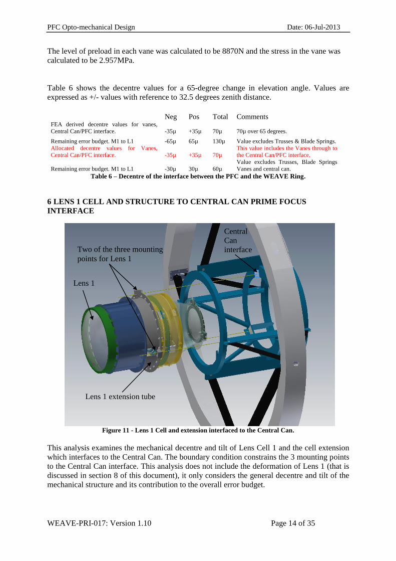
Figure 11 - Lens 1 Cell and extension interfaced to the Central Can.
This analysis examines the mechanical decentre and tilt of Lens Cell 1 and the cell extension
which interfaces to the Central Can. The boundary condition constrains the 3 mounting points
to the Central Can interface. This analysis does not include the deformation of Lens 1 (that is
discussed in section 8 of this document), it only considers the general decentre and tilt of the
mechanical structure and its contribution to the overall error budget.
Two of the three mounting
points for Lens 1
Lens 1 extension tube
Lens 1
Central
Can
interface
PFC Opto-mechanical Design Date: 06-Jul-2013
WEAVE-PRI-017: Version 1.10 Page 15 of 35
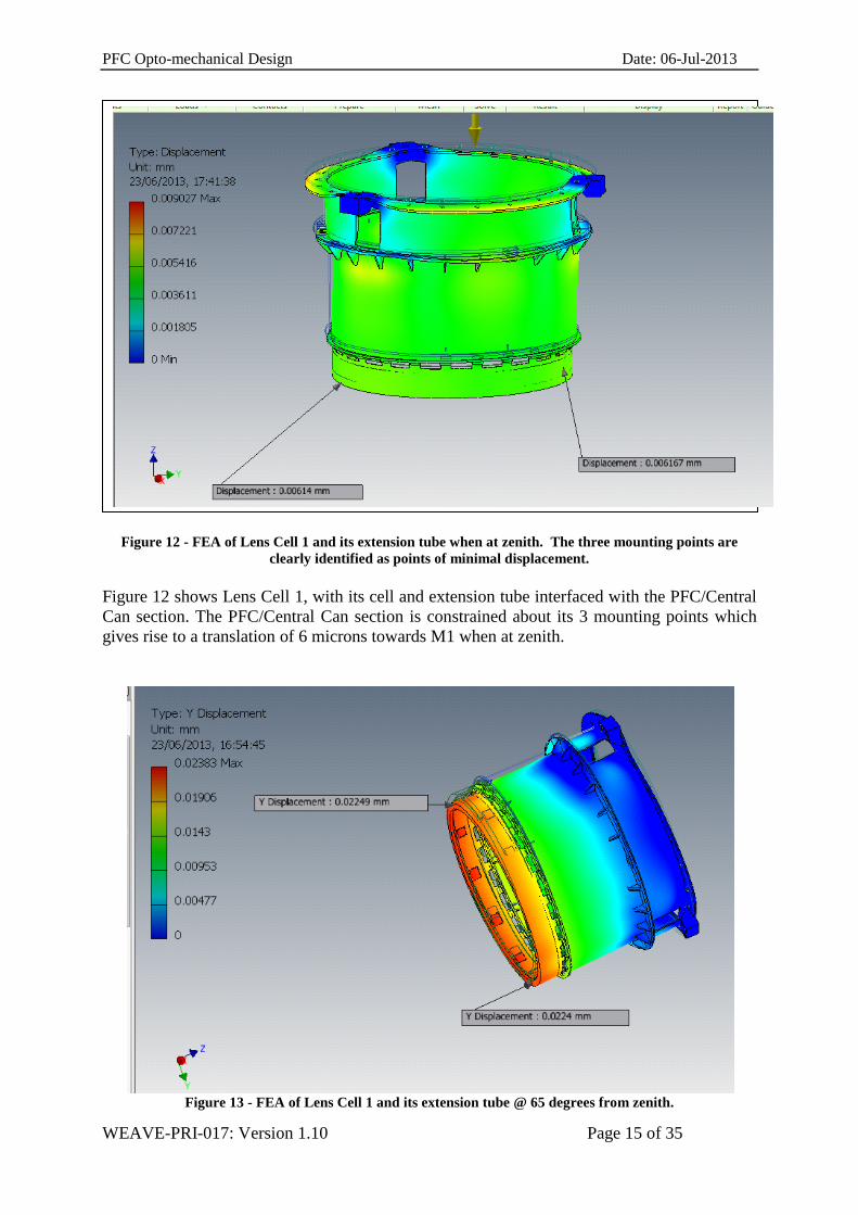
Figure 12 - FEA of Lens Cell 1 and its extension tube when at zenith. The three mounting points are
clearly identified as points of minimal displacement.
Figure 12 shows Lens Cell 1, with its cell and extension tube interfaced with the PFC/Central
Can section. The PFC/Central Can section is constrained about its 3 mounting points which
gives rise to a translation of 6 microns towards M1 when at zenith.
Figure 13 - FEA of Lens Cell 1 and its extension tube @ 65 degrees from zenith.
PFC Opto-mechanical Design Date: 06-Jul-2013
WEAVE-PRI-017: Version 1.10 Page 16 of 35
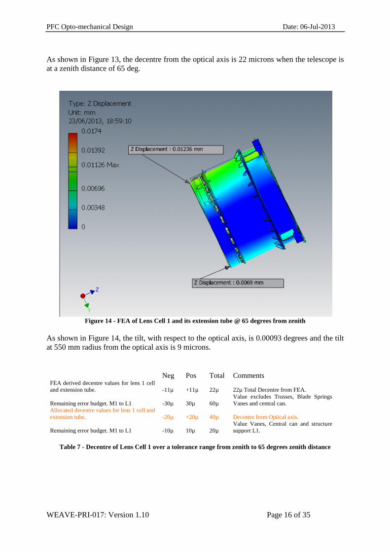
As shown in Figure 13, the decentre from the optical axis is 22 microns when the telescope is
at a zenith distance of 65 deg.
Figure 14 - FEA of Lens Cell 1 and its extension tube @ 65 degrees from zenith
As shown in Figure 14, the tilt, with respect to the optical axis, is 0.00093 degrees and the tilt
at 550 mm radius from the optical axis is 9 microns.
Neg Pos Total Comments FEA derived decentre values for lens 1 cell
and extension tube. -11µ +11µ 22µ 22µ Total Decentre from FEA.
Remaining error budget. M1 to L1 -30µ 30µ 60µ
Value excludes Trusses, Blade Springs
Vanes and central can.
Allocated decentre values for lens 1 cell and
extension tube. -20µ +20µ 40µ Decentre from Optical axis.
Remaining error budget. M1 to L1 -10µ 10µ 20µ
Value Vanes, Central can and structure
support L1.
Table 7 - Decentre of Lens Cell 1 over a tolerance range from zenith to 65 degrees zenith distance

PFC Opto-mechanical Design Date: 06-Jul-2013
WEAVE-PRI-017: Version 1.10 Page 17 of 35
7 SUMMARY OF ERROR BUDGET M1 /TO TOP-END UP TO PFC INTERFACE
This analysis is only preliminary and is intended to demonstrate how each component
contributes to the flexure error budget of maintaining the position of L1 with respect to M1.
The provisional figures are intended to provide a level of confidence that the final error
budget can be achieved for WEAVE. Development and optimization of the top-end structures
are essential as the preliminary designs are taken through to final designs.
Top End Displacement Neg Pos total Comments
Error Budget Allocation M1 to L1 -200µ +200 400µ
Total budget from optical error budget
excel spread sheet.
Target decentre values for the trusses -110µ 110µ 220µ
After measurements and optimisation
of truss performance. M1 to telescope
fixed ring.
Allocated Error budget for Blade Springs. -25µ +25µ 50µ
Blade Springs Interface. Top fixed ring
to WEAVE ring.
Allocated decentre values for vanes, Central
Can/PFC interface. -35µ +35µ 70µ
This value includes the Vanes through
to the Central Can/PFC interface.
Allocated decentre values for lens 1 cell and
extension tube. -20µ +20µ 40µ Decentre from Optical axis.
Remaining Error Budget M1 to L1. -10µ 10µ 20µ
Table 8 - Summary of mechanical flexure error budgets for structures M1 through to L1.
8 ANALYSIS AND DESCRIPTION OF LENS 1 AND ITS MOUNTING CELL
8.1 Introduction
Lens 1 is a large fused silica meniscus lens that needs to be mounted in a lens cell. The
mounting method adopted has to demonstrate that not only does it keep the lens within the
overall decentration and tilt error budgets with respect to M1 but it also needs to show that
induced stresses, and lens surface deformations are tolerable.
The following FEA results show how the original lens mount was not adequate and that the
latest chosen design, which is based on existing designs, is a much more suitable approach.
This analysis makes reference to lens surface deformation which is affected by the mounting
method. Detailed analysis of any lens surface deformation and its effect on image quality is
not discussed in this document but is dealt with in the document entitled “Final Design for the
WEAVE Prime Focus Corrector”.
As Lens 1 is the largest of the six lenses the assumption was made that if a suitable mounting
arrangement (that fulfils the requirements for this lens) could be identified, then it’s likely that
a suitable solution for the other lens mounts could also be identified (see Appendix B).

PFC Opto-mechanical Design Date: 06-Jul-2013
WEAVE-PRI-017: Version 1.10 Page 18 of 35
8.2 Original Lens Mount Design
Figure 15 - Lens 1 general dimensions and CoG.
FEA was performed to model the deformation of Lens 1 in its cell. Different lens cell mount
designs and concepts were analysed until an appropriate configuration was obtained. As this
analysis dealt with the critical glass support interface (of a very large lens) it was deemed
appropriate to contract two independent experts to perform the analysis. The final reports are:
13001-900001 FEA for corrector Lens 1 and cell. -OpTIC Glyndŵr Ltd, Ffordd
William Morgan, St Asaph Business Park, ST ASAPH, LL17 0JD, North Wales, UK
WEAVE_report_IV.ppt FEM Analysis of Lens 1. Konkoly Observatory, Hungary.
8.3 Original Lens Cell
Figure 16 - Lens 1 and the original lens cell mounting arrangement
Fused Silica Lens
231 kg

PFC Opto-mechanical Design Date: 06-Jul-2013
WEAVE-PRI-017: Version 1.10 Page 19 of 35
Both experts ascertained that the original cell design was inadequate on two counts:
1) Firstly, the three-point mounting arrangement, so close to the lens, deformed the lens
surface to such an extent that the required image quality was not maintained.
2) Secondly, the design did not provide an athermal solution which would maintain
image quality. Furthermore, over large temperature variations the design would
potentially put the optic at risk.
The deformation of the lens surface was 4
microns when held in the original cell
design at zenith.
The deformation of the lens surface was
2.7 microns when held in the original cell
design at 65 degrees from zenith. Figure 17 - Lens surface deformations using the original cell mounting arrangement.
8.4 Improved Design for Lens Cell 1
An improved design based on those used for the MMT and Dark Energy Camera (DECam)
was pursued (see Figure 18).

PFC Opto-mechanical Design Date: 06-Jul-2013
WEAVE-PRI-017: Version 1.10 Page 20 of 35
Figure 18 - Schematic representations of the lens cell mounting arrangements used in the DECam (top)
and MMT (bottom) designs.
Figure 19 - Lens 1 in the revised lens cell.
8.5 Lens 1 with Constraints Applied to Mounting Pads
The boundary constraints were applied as detailed in Figure 20. Fixed constraints were
applied at the locations where the lens cell interfaces to Lens 1. Gravity was applied as a
vector acceleration of 9.81 m/s2 to simulate each of the telescope tube orientations.

PFC Opto-mechanical Design Date: 06-Jul-2013
WEAVE-PRI-017: Version 1.10 Page 21 of 35
Figure 20 - Boundary Conditions for Lens 1
8.5.1 Results for Lens 1 with pads constrained (no cell included)
The results for the Lens 1 analysis are shown in the figures below. The nature of these
deflections is greatly affected by the altitude angle. The aberrations caused by deflection due
to self-weight can be seen to change from power to coma as the zenith angle changes. The
magnitudes are given adjacent to each plot.
Figure 21 - Lens L1 surface 1 deformation at zenith was 302.33nm.
Fixed
Constraints

PFC Opto-mechanical Design Date: 06-Jul-2013
WEAVE-PRI-017: Version 1.10 Page 22 of 35
Figure 22- Lens L1 surface 2 deformation at zenith was 249.896nm.
Figure 23 - Lens L1 surface 1 deformation at zenith angle 65 deg was 155.82nm.

PFC Opto-mechanical Design Date: 06-Jul-2013
WEAVE-PRI-017: Version 1.10 Page 23 of 35
Figure 24 - Lens L1 Surface 2 deformation at zenith angle 65 deg was 136.25nm.
These results illustrate the deformations due to gravity for each of the optical surfaces. The
values range from 137nm to 302nm over the useful range which is specified as zenith angles
of 0o - 65o. Furthermore, there will be residual forces from the support cell that will degrade
the performance of the optic. As such, the values shown in figures 21 to 24 should be
considered as the most optimistic that can be achieved by any mounting arrangement.
8.6 Lens 1 and its Cell
FEA plots were produced for Lens 1 and its cell, when the telescope is pointing at zenith and
at 65 degrees from zenith.
Figure 25 - Overall displacement values for L1 and its cell when the telescope is pointing at zenith.

PFC Opto-mechanical Design Date: 06-Jul-2013
WEAVE-PRI-017: Version 1.10 Page 24 of 35
At zenith, Lens 1 and its cell exhibit a 3-micron displacement towards M1. This is a focus
term. This analysis was ported to Zemax to extract detailed lens surface deformations. The
scope of this document does not include detailed analysis of lens deformation this is covered
in the WEAVE-PRI-014 document. The following is an extract from that document which
summarises the P-V deformations.
“FEA results for lens 1 surface 1 and surface 2, respectively, when the telescope is pointing at
zenith. The difference between the nominal and deformed surface shape is plotted in both
cases. The P-V deformation of the lens is 0.8 and 0.9 micron for the two surfaces”
Figure 26 - Lens 1 and its cell at 65 degrees
At 65 degree zenith distance, Lens 1 and its cell exhibit a 13-micron maximum displacement.
From Table 8, the error budget allocation is +/- 20 microns. This analysis was ported to
Zemax to extract detailed lens surface deformations. The scope of this document does not
include detailed analysis of lens deformation this is covered in the WEAVE-PRI-014
document. The following is an extract from that document which summarises the P-V
deformations.
“For surface 1 and surface 2 the P-V of the difference between the nominal and the deformed
surface shape is 6.5 and 3.4 microns respectively.”
PFC Opto-mechanical Design Date: 06-Jul-2013
WEAVE-PRI-017: Version 1.10 Page 25 of 35
9 ANALYSIS OF THE EFFECTS OF CHANGING THE SETUP OF THE RTV PADS
Further analyses with two sets of radial RTV pads produced good results with respect to lens
deformation but gave a very large tilt of the whole lens due to the RTV shearing which is not
helped by the lens CoG acting about the radial pads. With the telescope at 65 degrees zenith
distance, the displacement induced by the RTV pads was 388 microns.
Figure 27 - The tilt due to the RTV pads at 65 degrees zenith distance (left) and the exaggerated
deformation of the RTV pads (right).
The large scale tilts seen with this design are caused by the centre of gravity of the lens being
located approximately 87mm in front of the radial supports and the compliance of the RTV
material. Additionally, fitting the extra RTV gasket (see figure 29 right) to help with CTE
compensation has had a large detrimental effect on the displacement value. Unfortunately due
to the shape of the lens it is impractical to locate the radial supports at any other location. The
importance of RTV shape and thickness is critical. Calculating and defining the pad sizes for
CTE compensation, minimal displacement and stress is a complex and time consuming
process. This has been achieved before and is well documented in the literature. A first pass
calculation to size the shape and thickness of the RTV pads for Lens 1 and its cell is shown in
Appendix C.
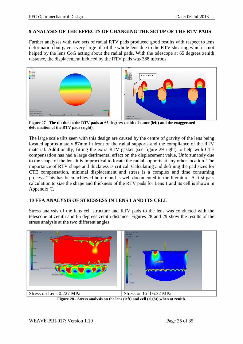
10 FEA ANALYSIS OF STRESSESS IN LENS 1 AND ITS CELL
Stress analysis of the lens cell structure and RTV pads to the lens was conducted with the
telescope at zenith and 65 degrees zenith distance. Figures 28 and 29 show the results of the
stress analysis at the two different angles.
Stress on Lens 0.227 MPa Stress on Cell 6.32 MPa
Figure 28 - Stress analysis on the lens (left) and cell (right) when at zenith.

PFC Opto-mechanical Design Date: 06-Jul-2013
WEAVE-PRI-017: Version 1.10 Page 26 of 35
Stress on Lens 0.19 MPa Stress on Cell 10.11 MPa Figure 29 - Stress analysis on the lens (left) and cell (right) when at 65 degrees zenith distance.
11 SUMMARY OF FEA DATA ON LENS 1 AND CELL
The improved design, using RTV pads and extending the three-point mounting arrangement
away from the lens, helps to reduce the lens surface deformations to an acceptable level.
Overall, displacement of the lens and lens cell fall below the error budget allocations given in
Table 8. Tilt and focus of L1, with respect to M1, is provided by actuation of the new
WEAVE top-ring.
FEA data collected when using RTV pads and RTV gaskets is poor with respect to tilt. The
importance of the “shape factor” (load surface area to edge surface area) is not only critical
for an athermal design but also for overall displacement of the lens in its cell.

PFC Opto-mechanical Design Date: 06-Jul-2013
WEAVE-PRI-017: Version 1.10 Page 27 of 35
Appendix A - Flexure Error Budget taken from the error budget spreadsheet.
Comp Unit
NEG
TOL
POS
TOL
Flexures 2 - Lens displacement due to gravity load - axial displacement can be compensated by TOP-END refocusing, tilt by optimizing to degrees zenith angle
LENS 1
lens displacement/tilt
axial displacement µm -25 25
decentre x µm -10 10
decentre y µm -70 70
tilt x deg -0.001 0.001
tilt y deg -0.01 0.01
ADC 1
lens displacement/tilt
axial displacement µm -25 25
decentre x µm -10 10
decentre y µm -40 40
tilt x deg -0.001 0.001
tilt y deg -0.01 0.01
ADC 2
lens displacement/tilt
axial displacement µm -25 25
decentre x µm -10 10
decentre y µm -40 40
tilt x deg -0.001 0.001
tilt y deg -0.01 0.01
LENS 6
lens displacement/tilt
axial displacement µm -20 20
decentre x µm -10 10
decentre y µm -30 30
tilt x deg -0.001 0.001
tilt y deg -0.01 0.01
IMA
IMA plane displacement/tilt
axial displacement µm -20 20
tilt x deg -0.001 0.001
tilt y deg -0.01 0.01
WHT wrt Corrector
top-end displacement/tilt
axial displacement µm -20 20
decentre x µm -25 25
decentre y µm -200 200
tilt x deg -7E-04 0.0007
tilt y deg -0.003 0.003

WEAVE-PRI-017: Version 0.10 Page 28 of 35
Appendix B – The initial FEA of Lens 2 deformation and the middle and end structures of
the PFC.
Figure 30 - General lens layout with Lens 2 highlighted.
Figure 31 - The PFC middle section (for ADC) and end section (for Lens 6) housings
Lens 2
Middle
Section
End
Section

WEAVE-PRI-017: Version 0.10 Page 29 of 35
Figure 32 - Lens 2 in lens cell.
Lens 2 (NBK7) is mounted in the same fashion as Lens 1 using multiple radial and axial pads.
This arrangement incorporates Delrin pads and a steel cell.
material
Diameter
(difference)
Radius
(difference) CTE
refere
nce
temp.
operat
ing
temp.
Radius
shrinkage
mm mm *10^-6 K K micron
LENS 2 axial
lens NBK7 150.000 75 7.1 298 268 16
spacer Delrin 6.500 3.25 120 298 268 12
mount Steel 156.500 78.25 12 298 268 28
total 0 The thickness of the CTE-compensating Delrin radial pads is 6.5 mm.
As shown in Figure 33, a preliminary check of the surface deformation of Lens 2, when the
lens is mounted at 65 degrees zenith distance, shows a deformation of 100nm (P-V) for
surface 1.
Figure 33 - FEA of lens when mounted in its cell at 65 degrees zenith distance.
Similarly, as shown in Figure 34, when the lens is mounted at zenith the deformation of
surface 1 is increased to 200nm (P-V) for the same surface.

WEAVE-PRI-017: Version 0.10 Page 30 of 35
Figure 34 - FEA of lens when mounted in its cell at zenith.
Analysis of middle section
Middle section loaded with ADC and cells at zenith
Decentre from optical axis 1.2 microns.
Axial displacement towards “L1” is 14 microns.
Tilt is less than 0.0001 degrees.

WEAVE-PRI-017: Version 0.10 Page 31 of 35
Middle section loaded with ADC optics and cells at 65 degrees from zenith.
Decentre from optical axis is 14 microns.
Axial displacement towards “M1” is 6 microns.
Tilt less than 0.0001 degrees.
Analysis of end section
End section loaded, at zenith, with Lens 6 and its cell.
Decentre from optical axis is 1 micron.
Axial displacement towards “ADC optics” is 3 microns.
Tilt is less than 0.0001 deg.

WEAVE-PRI-017: Version 0.10 Page 32 of 35
End section loaded with Lens 6 and its cell at 65 degrees from zenith
Decentre from optical axis is 2.3 microns.
Axial displacement towards “ADC optics” is 1 micron.
Tilt is less than 0.0001 degrees.
In summary, the deformation of Lens 2 appears to be acceptable and the flexure error budgets
for the housing are within the error budget allocation detailed in appendix A.

WEAVE-PRI-017: Version 0.10 Page 33 of 35
Appendix - C Sizing RTV Pads

WEAVE-PRI-017: Version 0.10 Page 34 of 35

WEAVE-PRI-017: Version 0.10 Page 35 of 35
Related Documents


