Description of PEM Fuel Cells System Diego Feroldi and Marta Basualdo Abstract This chapter provides a description of polymer electrolyte membrane (PEM) fuel cell-based systems and different modeling approaches. First, it shows the structure of a single cell, the advantages and disadvantages of this type of fuel cell, the expressions of the generated voltage and the efficiency, and the generic structure of a generation system based on PEM fuel cell. Second, the chapter provides a review of the principal models presented in the literature to describe the behavior of the system. Different types of PEM fuel cell models are presented, focusing on dynamic models suitable for control purposes. Particularly, this chapter describes in detail the dynamic model used as a base to represent the system in the subsequent chapters of the book. Then, the described model is used to study the optimal operation of a fuel cell at different loads, showing the benefits of an optimal operation in terms of hydrogen reduction and greater peak power. 1 Introduction The polymer electrolyte membrane fuel cell (PEMFC), also known as proton exchange membrane fuel cell, takes its name from the type of electrolyte: a poly- meric membrane with high proton conductivity when the membrane is conveniently D. Feroldi (B ) · M. S. Basualdo CAPEG-CIFASIS-(CONICET-UNR-UPCAM), 27 de Febrero 210 bis, S2000EZP Rosario, Argentina e-mail: [email protected] M. S. Basualdo UTN-FRRo, Zeballos 1341, S2000BQA Rosario, Argentina e-mail: [email protected] D. Feroldi DCC-FCEIA-UNR, Pellegrini 250, S2000BTP Rosario, Argentina M. S. Basualdo et al. (eds.), PEM Fuel Cells with Bio-Ethanol Processor Systems, 49 Green Energy and Technology, DOI: 10.1007/978-1-84996-184-4_2, © Springer-Verlag London Limited 2012

Welcome message from author
This document is posted to help you gain knowledge. Please leave a comment to let me know what you think about it! Share it to your friends and learn new things together.
Transcript
Description of PEM Fuel Cells System
Diego Feroldi and Marta Basualdo
Abstract This chapter provides a description of polymer electrolyte membrane(PEM) fuel cell-based systems and different modeling approaches. First, it shows thestructure of a single cell, the advantages and disadvantages of this type of fuel cell, theexpressions of the generated voltage and the efficiency, and the generic structure ofa generation system based on PEM fuel cell. Second, the chapter provides a reviewof the principal models presented in the literature to describe the behavior of thesystem. Different types of PEM fuel cell models are presented, focusing on dynamicmodels suitable for control purposes. Particularly, this chapter describes in detail thedynamic model used as a base to represent the system in the subsequent chaptersof the book. Then, the described model is used to study the optimal operation of afuel cell at different loads, showing the benefits of an optimal operation in terms ofhydrogen reduction and greater peak power.
1 Introduction
The polymer electrolyte membrane fuel cell (PEMFC), also known as protonexchange membrane fuel cell, takes its name from the type of electrolyte: a poly-meric membrane with high proton conductivity when the membrane is conveniently
D. Feroldi (B) · M. S. BasualdoCAPEG-CIFASIS-(CONICET-UNR-UPCAM),27 de Febrero 210 bis, S2000EZP Rosario, Argentinae-mail: [email protected]
M. S. BasualdoUTN-FRRo, Zeballos 1341, S2000BQA Rosario, Argentinae-mail: [email protected]
D. FeroldiDCC-FCEIA-UNR, Pellegrini 250, S2000BTP Rosario, Argentina
M. S. Basualdo et al. (eds.), PEM Fuel Cells with Bio-Ethanol Processor Systems, 49Green Energy and Technology, DOI: 10.1007/978-1-84996-184-4_2,© Springer-Verlag London Limited 2012
50 D. Feroldi and M. Basualdo
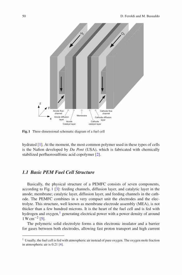
Fig. 1 Three-dimensional schematic diagram of a fuel cell
hydrated [1]. At the moment, the most common polymer used in these types of cellsis the Nafion developed by Du Pont (USA), which is fabricated with chemicallystabilized perfluorosulfonic acid copolymer [2].
1.1 Basic PEM Fuel Cell Structure
Basically, the physical structure of a PEMFC consists of seven components,according to Fig. 1 [3]: feeding channels, diffusion layer, and catalytic layer in theanode; membrane; catalytic layer, diffusion layer, and feeding channels in the cath-ode. The PEMFC combines in a very compact unit the electrodes and the elec-trolyte. This structure, well known as membrane electrode assembly (MEA), is notthicker than a few hundred microns. It is the heart of the fuel cell and is fed withhydrogen and oxygen,1 generating electrical power with a power density of around1 W cm−2 [5].
The polymeric solid electrolyte forms a thin electronic insulator and a barrierfor gases between both electrodes, allowing fast proton transport and high current
1 Usually, the fuel cell is fed with atmospheric air instead of pure oxygen. The oxygen mole fractionin atmospheric air is 0.21 [4].
Description of PEM Fuel Cells System 51
density. The solid electrolyte has the advantage, as opposed to those of liquid type,that allows the FC to operate in any spatial position [1].
The electrodes consist of a catalytic layer of great superficial area on a substratumof coal, permeable to gases. Electrocatalyst materials are necessary to obtain a goodoperation, increasing the speed of the chemical reaction. In this way, the gases canreact with a lower energy of activation, allowing the reaction to take place at a lowertemperature [3]. The electrocatalyst used in PEMFC is platinum, which is one of themajor drawbacks of this technology because of its high cost.
However, there are research advances of high temperature PEM fuel cells(HT-PEMFCs) in several fields because there are several reasons for operating attemperatures above 100◦C [6]. First, the electrochemical kinetics for the reactions incathode and anode are enhanced. Second, the water management issue can be simpli-fied because there would be no liquid water. Third, the cooling system is simplifieddue to the increased temperature gradient between the fuel cell stack and the coolant.Fourth, the waste heat can be exploited using cogeneration. Fifth, the tolerance to COis increased allowing the use of lower quality reformed hydrogen. Unfortunately, thearea of HT-PEMFCs is incipient and still needs much research to be implemented incommercial applications.
1.2 Advantages and Disadvantages of PEM Fuel Cells
The main advantage of PEM fuel cells is their high efficiency compared with otherenergy conversion devices [7]. This allows the efficiency of a fuel cell vehicle usingdirect-hydrogen FC2 to be twice that in a gasoline vehicle [8, 9]. Moreover, unlikethe internal combustion engines where the efficiency is maximum with the highestloads, the FC efficiency is also high with partial loads. This is advantageous becausein typical driving conditions, like urban and suburban scenarios, most of the time thevehicle is demanding a small fraction of the nominal FC power [10]. Thus, an FCvehicle will be working mostly at high efficiencies. At the same time, using direct-hydrogen FC, the local emissions problem in densely urban areas can be eliminated.
Another important advantage of PEMFC, in contrast to other types of fuel cells,is the low operation temperature (below 80◦C) [11], allowing to reach the operationpoint quickly. In addition, the cost of the materials is smaller than for the hightemperature fuel cells (except the catalyst, which is based on platinum) and theiroperation is safer. All these characteristics turn PEMFC particularly appropriatefor applications in vehicles. Nevertheless, it is necessary to use better, and moreeconomic, catalyst so that the reaction occurs at lower temperatures.
The main disadvantage of fuel cells is their high cost and the high production costof hydrogen. Hydrogen is preferred because of the fast electrochemical reaction, and
2 Direct-hydrogen FC refers to an FCS that is directly fed with hydrogen from a pressurized tankopposite to the case where the hydrogen is produced with an on-site reformer.
52 D. Feroldi and M. Basualdo
its high specific energy.3 Nevertheless, as it was mentioned, hydrogen is not a primaryfuel. Usually, it is produced from hydrocarbon reforming or water electrolysis [1, 13].The use of electrolysis is advisable especially when some type of renewable energyis used, avoiding fossil fuel use. It is expected that the cost of fuel cells and hydrogenwill diminish with the progress in technology. Thus, hydrogen has the possibilitiesof becoming an alternative to fossil fuels with the joint use of renewable energies.
1.3 Fuel Cell Voltage
The standard potential E0 is a quantitative measurement of the maximum cell poten-tial, i.e., the open circuit voltage. For a hydrogen–oxygen cell, in which there is atransfer of two electrons by each water molecule, E0 = 1.229 V if the producedwater is in liquid state and E0 = 1.18 V if the produced water is in gaseous state[13]. These values correspond to normalized conditions: cell temperature (Tfc) equalto 298.5 K and partial pressures of oxygen (pO2) and hydrogen (pH2) equal to 1 atm.In the work of Amphlett et al. [14], the following expression of E0 is given, depend-ing on the temperature and the reactant partial pressures, which are used in severalmodels of fuel cells e.g., [4, 15]:
E0 = 1.229 − 8.5 × 10⁻⁴ (Tfc − 298.5)
+ 4.3085 × 10⁻⁵Tfc
[ln
(pH2
) + 1
2ln
(pO2
)]. (1)
However, in practice the cell potential is significantly lower than the theoreticalpotential because there are some losses even when no external load is connected.Moreover, when a load is connected to the fuel cell, the voltage in the terminalsdecreases still more due to a number of factors, including polarization losses andinterconnection losses between cells. The main voltage losses in a fuel cell are thefollowing [1, 13, 16]:
Activation loss The activation losses vact are caused by the slowness of the reactionthat takes place on the surface of the electrodes. A proportion of the generated voltageis lost in maintaining the chemical reaction that transfers electrons from the negativeelectrode toward the positive electrode. This phenomenon is strongly nonlinear, andmore important, it is at low current densities.
Fuel crossover and internal currents These energy losses result from the wasteof fuel passing through the electroslyte and from electron conduction through theelectrolyte. In PEMFC, the fuel losses and internal current are small and their effectsare usually negligible.
3 The Specific Energy of hydrogen at ambient pressure is 8890 W h kg−1, meanwhile the corre-sponding one of petrol is 694 W h kg−1. However, the necessary volume for its storage is greater.The energy density of petrol is 500 W h dm−3, meanwhile for hydrogen (300 bar) is 55 W h dm−3
[12].
Description of PEM Fuel Cells System 53
0 0.1 0.2 0.3 0.4 0.5 0.6 0.7 0.8 0.90.5
0.6
0.7
0.8
0.9
1
Pot
entia
l [V
]
0 0.1 0.2 0.3 0.4 0.5 0.6 0.7 0.8 0.90
0.1
0.2
0.3
0.4
0.5
0.6
Pow
er d
ensi
ty [W
cm
−2 ]
Current density [A cm−2]
PotentialPower density
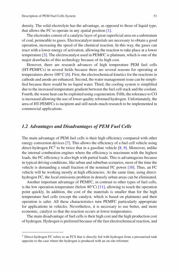
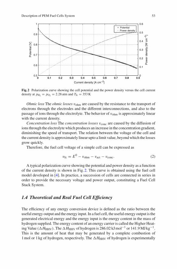
Fig. 2 Polarization curve showing the cell potential and the power density versus the cell currentdensity at pH2 = pO2 = 2.28 atm and Tfc = 353 K
Ohmic loss The ohmic losses vohm are caused by the resistance to the transport ofelectrons through the electrodes and the different interconnections, and also to thepassage of ions through the electrolyte. The behavior of vohm is approximately linearwith the current density.
Concentration loss The concentration losses vconc are caused by the diffusion ofions through the electrolyte which produces an increase in the concentration gradient,diminishing the speed of transport. The relation between the voltage of the cell andthe current density is approximately linear upto a limit value, beyond which the lossesgrow quickly.
Therefore, the fuel cell voltage of a simple cell can be expressed as
vfc = E0 − vohm − vact − vconc. (2)
A typical polarization curve showing the potential and power density as a functionof the current density is shown in Fig. 2. This curve is obtained using the fuel cellmodel developed in [4]. In practice, a succession of cells are connected in series inorder to provide the necessary voltage and power output, constituting a Fuel CellStack System.
1.4 Theoretical and Real Fuel Cell Efficiency
The efficiency of any energy conversion device is defined as the ratio between theuseful energy output and the energy input. In a fuel cell, the useful energy output is thegenerated electrical energy and the energy input is the energy content in the mass ofhydrogen supplied. The energy content of an energy carrier is called the Higher Heat-ing Value (�HHHV). The �HHHV of hydrogen is 286.02 kJ mol−1 or 141.9 MJ kg−1.
This is the amount of heat that may be generated by a complete combustion of1 mol or 1 kg of hydrogen, respectively. The �HHHV of hydrogen is experimentally
54 D. Feroldi and M. Basualdo
determined by reacting a stoichiometric mixture of hydrogen and oxygen in a steelcontainer at 25◦C. If hydrogen and oxygen are combined, water vapor emerges at hightemperatures. Then, the container and its content are cooled down to the original 25◦Cand the �HHHV is determined by measuring the heat released between the identicalinitial and final temperatures. On the contrary, if the cooling is stopped at 150◦C, thereaction heat is only partially recovered (241.98 kJ mol−1or 120.1 MJ kg−1). This isknown as the lower heating value (�HLHV) of hydrogen [17].
Assuming that all the Gibbs free energy of hydrogen,4 �G, can be converted intoelectrical energy, the maximum possible (theoretical) efficiency of a fuel cell is [16]
ηHHV = −�G/ − �HHHV = 237.34/286.02 = 83%. (3)
However, the �HLHV is used very often to express the fuel cell efficiency to com-pare it with the internal combustion engine, whose efficiency has traditionally beenexpressed using the fuel �HLHV. In this case, the maximum theoretical fuel cellefficiency results in a higher number:
ηLHV = −�G/ − �HLHV = 228.74/241.98 = 94.5%. (4)
If both �G and �HLHV in (3) are divided by 2F, where 2 is the number ofelectrons per molecule of H2 and F is the Faraday number, the fuel cell efficiencymay be expressed as a ratio of two potentials:
ηHHV = −�G
−�HHHV=
−�G2F
−�HHHV2F
= 1.23
1.482= 83%, (5)
where −�G2F = 1.23V is the theoretical cell potential, and −�HHHV
2F = 1.482V is thepotential corresponding to the �HLHV, or thermoneutral potential.
In this section, we analyzed the theoretical fuel cell efficiency. However, asexplained in the previous sections, in a real fuel cell the efficiency is quite lowerand also depends on the fuel cell current. The fuel cell efficiency ηFC can also bedefined as the ratio between the power produced and the power of hydrogen con-sumed [16]:
ηHHV = PFC
PH2
=Vfc Ifc−�HHHV Ifc
2F= Vfc
1.482, (6)
ηLHV = PFC
PH2
=Vfc Ifc−�HLHV Ifc
2F= Vfc
1.254, (7)
where Vfc is the generated voltage and Ifc is the fuel cell current. Thus, the FCefficiency is related to the actual voltage, which is related to the fuel cell currentthrough the polarization curve.
4 The Gibbs free energy is used to represent the available energy to do external work. The changesin Gibbs free energy �G are negative, which means that the energy is released from the reaction,and varies with both temperature and pressure [18].
Description of PEM Fuel Cells System 55
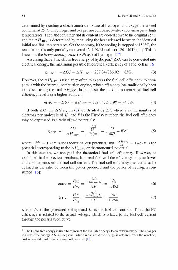
Fig. 3 Efficiency curve of a fuel cell system
Moreover, in a real system it is necessary to incorporate some auxiliary systemswhich consume a fraction of the generated power. As a result, the efficiency of thefuel cell system, ηfcs, is even lower than that expressed in Eq. 6:
ηfcs = ηHHVPnet
Pfc= ηHHV
Pfc − Paux
Pfc= ηHHV
(1 − Paux
Pfc
), (8)
where Pnet is the net power output, Pfc is the fuel cell power, and Paux is the powerconsumed by the auxiliary components, which include, in particular, the air com-pressor. The efficiency curve of a fuel cell system of 50 kW modelled in ADvancedVehIcle SimulatOR (ADVISOR)5 is shown in Fig. 3.
1.5 Generic Structure of a Fuel Cell-Based PowerGeneration System
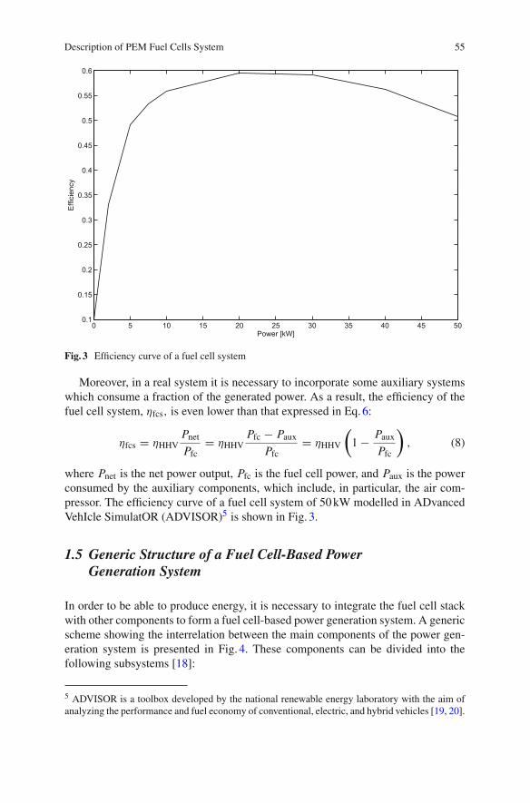
In order to be able to produce energy, it is necessary to integrate the fuel cell stackwith other components to form a fuel cell-based power generation system. A genericscheme showing the interrelation between the main components of the power gen-eration system is presented in Fig. 4. These components can be divided into thefollowing subsystems [18]:
5 ADVISOR is a toolbox developed by the national renewable energy laboratory with the aim ofanalyzing the performance and fuel economy of conventional, electric, and hybrid vehicles [19, 20].
56 D. Feroldi and M. Basualdo
Fig. 4 General scheme of a FCS oriented to automotive applications
1.5.1 Reactant Flow Subsystem
The reactant flow subsystem consists of the hydrogen and air supply circuits. Theobjective is to supply the adequate reactant flow to ensure fast transient responseand minimal auxiliary power consumption. The hydrogen supply circuit is generallycomposed of a pressurized tank with pure H2 connected to the anode through apressure-reduction valve and a pressure-controlled valve, meanwhile, the air supplycircuit is generally composed of an air compressor which feeds the cathode withpressurized air from the atmosphere. The anode output is generally operated in dead-ended mode and a purge valve in the anode output is periodically opened to removethe water and accumulated nitrogen gas. In case the anode output is not closed itis possible to reinject the out-flowing hydrogen into the anode input. On the otherhand, the cathode output is normally open through a fixed restriction. The cathodeair supply will be studied in Chap. 3 where we propose to close the cathode outputwith a controlled valve.
1.5.2 Heat and Temperature Subsystem
The heat and temperature subsystem includes the fuel cell stack cooling system andthe reactant heating system. The thermal management of the fuel cell is critical sincethe performance depends strongly on the temperature. The stack temperature controlcan be done using a fan or a water refrigeration subsystem.
Description of PEM Fuel Cells System 57
1.5.3 Water Management Subsystem
The objective of the water management subsystem is to maintain an effective hydra-tion of the polymer membrane and an adequate water balance, because the fuel cellperformance is also strongly dependent on membrane hydration. Both the air andthe hydrogen, are usually humidified before entering the fuel cell with humidifiers inboth circuits. The water that leaves the cathode can be recovered in a water separatorand reinjected in the humidifiers through a pump.
1.5.4 Power Conditioning Subsystem
Fuel cells generate an unregulated DC voltage which drops off when the currentincreases according to the polarization curve. In general, some power conditioningactions are necessary to supply the load properly. Such actions make necessary theuse of DC/DC regulators and/or inverter regulators.
1.5.5 Power Management Subsystem
The power management subsystem controls the power drawn from the fuel cell stack.If no energy storage devices are used, the full load must be supplied by the fuel celland no power management is necessary. However, if an energy storage system isincluded, such as batteries or supercapacitors, it is necessary to implement a powermanagement between these two power sources. A review of fuel cell hybrid systemsis described in the following section and a detailed study is done in Chap. 4.
1.6 Modeling of Polymer Electrolyte Membrane Fuel Cell Systems
Validated mathematical models provide powerful tools for the development andimprovement of fuel cell-based systems. Mathematical models can be used todescribe the fundamental phenomena that take place in the system to predict thebehavior under different operating conditions and to design and optimize the controlof the system.
The fuel cell system models describe quantitatively the physical and electrochem-ical phenomena that take place in to the cells. The models can be divided into twogroups [3]: empirical models and mechanistic models. Most of the empirical modelsare focused on the prediction of the polarization curve, which is used to characterizethe electrical operation of the FC, by means of empirical equations. The followingempirical equation developed by Kim et al. [21] is used to calculate the voltage (E)at different current densities (J), fitting experimental data at several temperatures,pressures, and oxygen compositions in the cathode gas mixture:
E = E0 − b logJ − R J − m exp(n J ), (9)
58 D. Feroldi and M. Basualdo
where E0 is the thermodynamic open-circuit voltage. The exponential term char-acterizes the mass-transport region of the polarization curve, the zone where theincrease in slope of the pseudo-linear region and the subsequent rapid fall-off of thecell potential. The parameter n has more pronounced effects than the parameter min this region. The terms E0 and b yield the electrode kinetic parameters for oxygenreduction in the cell. R represents the resistance, predominantly ohmic, and, slightly,the charge-transfer resistance of the electro-oxidation of hydrogen.
Later, Squadrito et al. [22] used an empirical approach to account the mass trans-port limitation, modifying the model of Kim et al. by replacing the last term of(9) with
[m J n ln (1 − J/Jlim)
]where m and n are empirically determined constants
and Jlim is the limiting current density obtained by fitting experimental data. Theequation describes experimental data over the full range of current density takinginto account possible mass transport limitations. The empirical equation was used tofit experimental data obtained from a single cell, showing good agreement betweentheoretical and experimental data.
One example of an empirical model widely used is the model developed byAmphlett et al. [14], which incorporates as much empirical properties as mecha-nistic to obtain a transient model able to predict the FC voltage as a function ofthe current, the FC temperature and the hydrogen and oxygen partial pressures fora 35-cell 5 kW PEM fuel cell. The model works well for the experimental systemin study but can be generalized to any other system recalculating the values of themodel.
On the other hand, the mechanistic model considers the fundamental phenomenain detail such as, heat and mass transport, forces, and electrochemical processes.Mechanistic modeling (single and multi-domain) has been utilized to study a widerange of phenomena including polarization effects (activation, ohmic and concentra-tion overpotentials), water management, thermal management, CO kinetics, catalystutilization and flow field geometry [23]. All these models are parametric in the sensethat they account for the cell performance of various input parameters, typicallytemperature, pressure and humidity.
Many of the mechanistic models are one-dimensional where only the directionacross the fuel cell is taken into account. Some of the first works dealing with thistype of models are [24–26]. Then two-dimensional and three-dimensional modelswere developed. Some two-dimensional models describe the plane perpendicularthrough the flow channels [27, 28] while others simulate the fuel cell along the flowchannels [29, 30]. Within the three-dimensional models can be mentioned the modeldeveloped by Nguyen et al. [31], which is a three-dimensional model of a PEM fuelcell with serpentine gas channels, and the model developed by Natarajan [32].
Some of the earlier works focused in the humidification problem, addressing thehumidification requirements of the inlet gases to maintain the water balance [33].Fuller and Newman [34] also addressed the water and thermal management, similarto Nguyen and White [29] who studied different forms of gas humidification andwater management, analyzing the cell performance. The model of Wöhr et al. [35]showed that for fuel cell stacks water management becomes even more difficult and
Description of PEM Fuel Cells System 59
is strongly related to thermal management. The temperatures of the inner cells of thestack are higher than the outer cells resulting in membrane dehydration.
Another approach to fuel cell modeling is the use of equivalent circuits to representthe system behavior. In fact, one of the most attractive aspects of the ElectrochemicalImpedance Spectroscopy as a tool for investigating the electrical and electrochemicalproperties of materials and systems, is the direct connection that often exists betweenthe behavior of a real system and that of an idealized model circuit consisting of dis-crete electrical components [36]. The procedure typically consist in the comparisonor fitting the impedance data to an equivalent circuit, which is representative of thephysical processes taking place in the system under investigation. There are analogiesbetween the circuit elements and the electrochemical processes, so that the resultsof data fitting can be more easily converted into physical understanding.
Many authors have studied the modeling approach based on equivalent elec-trical circuits, consisting of an arrangement of different electrical components tohave the same frequency response as that obtained by electrochemical impedancespectroscopy tests [37–40]. Some works present equivalent circuits using electri-cal elements, such as resistances, capacitances or inductance. However, other worksuse additional distributed elements that represent electrochemical or mass and ionictransport phenomena. For example, Warburg impedance represents the impedance ofone-dimensional distributed diffusion of a species in an electrode. Another exampleis a constant phase element, used for describing a distributed charge accumulationon rough irregular electrode surfaces.
However, there are some problems in using analogies to describe electrochemicalsystems: one of them is that different equivalent circuits obtain the same frequencyresponse, another problem is the overlapping frequency response of different phe-nomena and the dependence of the electrochemical phenomena on the operatingconditions (temperature, current, pressure, etc.).
So far we have seen different types of models that study the cell behavior in bothstationary and transient states. Nevertheless, there are few dynamic models suitablefor control purposes. In the work of Pukrushpan et al. [4] a dynamic model forPEMFCS that is suitable for the control study has been developed. The model capturesthe transitory behavior of the air compressor, the gases filling dynamics (in thecathode and anode), and the effect of the membrane humidity. These variables affectthe cell voltage and, therefore, the efficiency and the output power. The polarizationcurve in this model is a function of the hydrogen and oxygen partial pressures, thestack temperature and the membrane water content. This allows to evaluate the effectof variations of oxygen concentration and membrane humidity in the output voltage,which are necessary to make the control during transitory operation.
Another practical model oriented to control was developed by Del Real et al. [41]where the model parameters have been adjusted specifically for a 1.2 kW Ballardstack, which is considered a benchmark as it is widely used by research groups in thePEM fuel cell field. The model can predict both steady and transient states subject tovariable loads (including flooding and anode purges), as well as the system start-up.The proposed model methodology is accurate since the simulated results show goodagreement, compared to experimental data from the Ballard stack.
60 D. Feroldi and M. Basualdo
On the other hand, a dynamic model which incorporates the effects of chargedouble layer capacitance, the dynamics of flow and pressure in the anode and cath-ode channels and mass/heat transfer transient features in the fuel cell body has beenpresented [42]. This dynamic model can predict the transient response of cell volt-age, temperature of the cell, hydrogen/oxygen out-flow rates and cathode and anodechannel temperatures/pressures under sudden change in load current. The simulationresults are analyzed and compared to benchmark results, reporting that a good agree-ment is found between tests and simulations. Similarly, a dynamic electrochemicalmodel of a grid independent fuel cell power plant is presented in [43]. The modelincludes the methanol reformer, the PEM stack and the power conditioning unit. Themodel is used to predict the output voltage when subjected to rapid changes in aresidential load connected to it, showing a high degree of accordance. More recently,a semi-empirical dynamic model for stack voltage, based on experimental investiga-tion, was presented [44]. The proposed model can predict the transient response ofstack voltage under step change in current with good agreement between tests andsimulations.
The model developed by Pukrushpan et al. [4], which has been employed in severalworks for control purposes [45–51], is utilized in this book as a base to represent thebehavior of a generic fuel cell system. The model is described in detail in Sects. 1and 2.
1.7 Description of the Fuel Cell System Model
The model developed by Pukrushpan et al. [4] is used in several chapters of this bookas a base to characterize the dynamic behavior and performance of PEM fuel cellsystems. This model contains four main subsystems that interact with each other:
• FC voltage subsystem• Membrane hydration subsystem• Cathode flow subsystem• Anode flow subsystem
The spatial variation of the parameters is not considered and, thus, they are treatedas lumped parameters. On the other hand, the time constants of the electrochemicalreactions are in the order of magnitude of 10−19 s despite another work [52] arguesthat this constants are significatively lower (10−9 s). In any case, all the literatureagrees in the fastness of the electrochemical reactions, as remarked in [53] and [42].Thus, for control purpose, these time constants can be assumed negligible comparedto other constants much slower: temperature (102 s) and dynamics of volume filling(10−1 s).
In this book, this base model has been modified to adapt it to the proposed controlstructures described in Sect. 2. In the original model there is only one control variable:the compressor motor voltage. In this book, it is proposed to add an extra variable,the throttle opening area in the cathode output (At ), adding a control valve in the
Description of PEM Fuel Cells System 61
cathode output. The advantages of this new configuration are covered in detail inSect. 2.3.
Usually, in model-based control, it is necessary to find simplified models, derivedfrom the complete ones or from experimental data, to be used as inner models intothe controller. Here, the step response is utilized to obtain a simplified model that isused as internal model to predict the future process response in the control strategyimplemented in Sect. 2. The main advantage of this simplified model is that it iseasily obtainable through experimental data with good agreement with respect to theoriginal nonlinear system in the considered operating point.
1.8 Principal Equations in the Fuel Cell System Model
The model described in the previous section has the following governing equationswhere the mass of air in the supply manifold, the masses of oxygen, nitrogen andwater in the cathode and the masses of hydrogen and water in the anode are definedusing the principle of mass conservation [45]:
dmsm
dt= Wcp − Wsm,out, (10)
dmO2,ca
dt= WO2,ca,in − WO2,ca,out − WO2,rct, (11)
dmN2,ca
dt= WN2,ca,in − WN2,ca,out, (12)
dmw,ca
dt= Wv,ca,in − Wv,ca,out − Wv,ca,gen + Wv,m, (13)
dmH2
dt= WH2,an,in − WH2,an,out − WH2,rct, (14)
dmw,an
dt= Wv,an,in − Wv,an,out − Wv,m − Wl,an,out, (15)
where
• Wcp is the compressor flow,• Wsm,out is the outlet mass flow,• WO2,ca,in is the mass flow rate of oxygen gas entering the cathode,• WO2,ca,out is the mass flow rate of oxygen leaving the cathode,• WO2,rct is the mass flow rate of oxygen reacted,• WN2,ca,in is the mass flow rate of nitrogen gas entering the cathode,• WN2,ca,out is the mass flow rate of nitrogen gas leaving the cathode,• Wv,ca,in is the mass flow rate of vapor entering the cathode,• Wv,ca,out is the mass flow rate of vapor leaving the cathode,• Wv,ca,gen is the rate of vapor generated in the fuel cell reaction,
62 D. Feroldi and M. Basualdo
• Wv,menbr is the mass flow rate of water across the fuel cell membrane,• Wl,ca,out is the mass flow rate of liquid water leaving the cathode,• WH2,an,in is the mass flow rate of hydrogen gas entering the anode,• WH2,an,out is the mass flow rate of hydrogen gas leaving the anode,• WH2,rct is the rate of hydrogen reacted,• Wv,an,in is the mass flow rate of vapor entering the anode,• Wv,an,out is the mass flow rate of vapor leaving the anode,• Wv,m is the mass flow rate of water transfer across the fuel cell membrane, and• Wl,an,out is the rate of liquid water leaving the anode.
The voltage of a fuel cell stack consisting of n fuel cells is given as
vst = n · vfc, (16)
where the voltage of a single fuel cell is defined as
vfc = E − vact − vohm − vconc (17)
with E being the open circuit voltage and vact, vohm and vconc being the activation,ohmic and concentration overpotentials, respectively. By fitting experimental datato the phenomenological model equations, the open circuit voltage and the threeoverpotentials are respectively defined as
E = 1.229 − 0.85 × 10⁻³(Tfc − Tamb)
+ 4.3085 × 10⁻⁵Tfc ×[
ln(1.01325pH2) + 1
2ln(1.01325pO2)
]. (18)
The activation voltage is
vact = v0 + va(1 − ec1i ) (19)
with
v0 = 0.279 − 8.5 × 10⁻⁴(Tfc − Tamb) + 4.308 × 10⁻⁵Tfc
×[
ln
(pCa − psat(Tfc)
1.01325
)+ 1
2ln
(0.1173(pCa − psat(Tfc))
1.01325
)], (20)
va = (−1.618 × 10⁻⁵Tfc + 1.618 × 10⁻²)
×( pO2
0.1173+ psat(Tfc)
]2
+ (1.8 × 10⁻⁴Tfc − 0.166)( pO2
0.1173+ psat(Tfc)
)
(−5.8 × 10⁻⁴Tfc + 0.5736), (21)
Description of PEM Fuel Cells System 63
and
c1 = 10. (22)
The ohmic voltage is
vohm = i Rohm (23)
with the fuel cell electrical resistance
Rohm = tmσm
, (24)
the membrane conductivity
σm = (b11μm − b12) exp
[b2
(1
303− 1
Tfc
)]
b11 = 5.139 × 10⁻³, b12 = 3.26 × 10⁻³, b12 = 350 (25)
and
vconc = i
(c2
i
imax
)c3
(26)
with
c2 =
⎧⎪⎪⎪⎪⎪⎪⎨⎪⎪⎪⎪⎪⎪⎩
(7.16 × 10⁻⁴Tfc − 0.622)( pO2
0.1173 + psat(Tfc))
+(−1.45 × 10⁻³Tfc + 1.68) for( pO2
0.1173 + psat(Tfc))
< 2 atm
(8.66 × 10⁻⁵Tfc − 0.068)( pO2
0.1173 + psat(Tfc))
+(−1.6 × 10⁻⁴Tfc + 0.54) for( pO2
0.1173 + psat(Tfc))
≥ 2 atm
(27)
and
imax = 2.2, c3 = 2. (28)
The governing equations for the supply manifold pressure and the return manifoldpressure are respectively defined using the energy conservation principle and thestandard thermodynamics relationships as follows:
dpsm
dt= γ Ra
Vsm(WcpTcp − Wsm,outTsm), (29)
dprm
dt= RaTrm
Vrm(Wca,out − Wrm,out), (30)
where Vsm is the supply manifold volume, Vrm is the return manifold volume, Tsmis the supply manifold air temperature, Trm is the return manifold air temperature,
64 D. Feroldi and M. Basualdo
Tcp is the temperature of the air leaving the compressor, Ra is the air gas constant,and γ is the air specific heat ratio.
To express the governing equations in terms of the states, the closure relationsEqs. 31–38 are used. The supply manifold outlet air rate Wsm,out is related to thesupply manifold pressure psm and the cathode pressure pca via the linearized nozzleequation:
Wsm,out = ksm,out(psm − pca), (31)
where ksm,out is the supply manifold outlet orifice constant.The inlet oxygen, nitrogen, and cathode vapour mass flow rates, WO2,in, WN2,in,
and Wv,ca,in are related to the cathode inlet air mass flowrate, the inlet air humidity andthe mass fraction of oxygen and nitrogen in dry air using the ideal gas relations. Theoutlet oxygen, nitrogen and cathode vapour mass flow rates, WO2,out, WN2,out, andWv,ca,out, are likewise related to the outlet air mass flowrate, the outlet air humidityand the mass fraction of the oxygen and nitrogen in dry air at the cathode outlet usingthe ideal gas relations. The reacted oxygen and hydrogen and generated water vapor(in the cathode) mass flow rates, WO2,rct, WH2,rct, and Wv,ca,gen, are related to thefuel cell current:
WO2,rct = MO2
nIfc
4F, (32)
WH2,rct = MH2
nIfc
2F, (33)
Wv,ca,gen = Mv
nIfc
2F, (34)
where the constants 4 and 2 in the denominators denote the of electrons involved inthe oxidation and the reduction half-reactions respectively, MO2 is the molar massof oxygen, MH2 is the molar mass of hydrogen, Mv is the molar mass of vapor, andF is the Faraday constant.
The water mass flowrate through the membrane, Wv,m, is defined using the hydra-tion model. The outlet hydrogen and water masses are assumed to be zero, that is,hydrogen is assumed to react completely in the anode, while water generated by theoxidation half-reaction is assumed to be transported via electro-osmosis through themembrane towards the cathode.
The governing equation for the rotational speed of the compressor is defined bythe power conservation principle as
Jcpdωcp
dt= τcm − τcp, (35)
where Jcp is the combined inertia of the compressor and the motor (kg. m2), ωcpis the compressor speed (rad/sec), τcm is the compressor motor torque input (Nm)
Description of PEM Fuel Cells System 65
calculated in Eq. 36, and τcp is the torque required to drive the compressor (Nm)calculated in Eq. 37.
The compressor motor torque τcm is related to the compressor motor voltage Vcmand the compressor motor rotational speed ωcp by the static motor equation:
τcm = ηcmkt
Rcm
(Vcm − kv.ωcp
), (36)
where kt , Rcm, and kv are motor constants and ηcm is the motor mechanical efficiency.The steady state compressor torque τcp is related to the supply manifold pressure,the compressor motor rotational speed and the compressor air flowrate Wcp via thethermodynamic relations
τcp = CP
ωcp
Tatm
ηcp
[(psm
patm
)(γ−1)/γ
− 1
]Wcp, (37)
where C p is the air specific heat, ηcp is the compressor efficiency, and Tatm and patmare the atmospheric temperature and pressure, respectively.
The air temperature in the compressor, Tcp, is defined using basic thermodynamicrelations
Tcp = Tatm + Tatm
ηcp
[(psm
patm
)(γ−1)/γ
− 1
]. (38)
The air temperature in the supply manifold, Tsm, is obtained from msm, psm andVsm using the ideal gas law. The cathode outlet air flowrate Wca,out is related tothe cathode pressure and return manifold pressure via a linearized nozzle equationanalogous to Eq. 31. The return manifold outlet air flowrate Wrm,out is defined usinga non-linearized nozzle relation as discussed in Sect. 2.2, while the return manifoldair temperature Trm is considered to be constant and equal to the temperature of thefuel cell stack.
The flowrate of water through the membrane is controlled by two transport phe-nomena: electroosmotic drag of water molecules by the protons and back-diffusionfrom the cathode towards the anode. The transport phenomena is defined as
Wv,m = Mv Afcn
(nd
i
F− Dw
(Cv,ca − Cv,an)
tm
), (39)
where the electroosmotic drag coefficient is given as
nd = 0.0029μ2m + 0.05μm − 3.4 × 10⁻¹⁹ (40)
and μm is the mean water content in the membrane. The water content is defined as
ui =
⎧⎪⎨⎪⎩
0.043 + 17.81ai − 39.85a2i + 36.0a3
i , 0 < ai ≤ 1
14 + 1.4(ai − 1), 1 < ai ≤ 3
(i = m, an, ca)
(41)
66 D. Feroldi and M. Basualdo
where the water vapour activity is defined as
ai = xv,i pi
psat,i= pv,i
psat,i(i = an, ca). (42)
The average water vapour activity in the membrane is defined as
am = aan + aca
2(43)
and the water diffusion coefficient is given as
DW = Dλ exp
[2416
(1
303− 1
Tfc
)]× 10−4 (44)
with the preexponential term
Dλ =
⎧⎪⎪⎪⎪⎨⎪⎪⎪⎪⎩
10−6, μm < 2
10−6[1 + 2(μm − 2)], 2 ≤ μm ≤ 3
10−6[3 − 1.67(μm − 3)], 3 < μm < 4.5
1.25 × 10⁻⁶, μm ≥ 4.5
(45)
The water concentration at the membrane surfaces on anode and cathode sides inEq. 39 is a function of the membrane water content
Cv,i = ρm,dry
Mm,dryμi (i = an, ca), (46)
where ρm,dry (kg/cm3) is the membrane dry density and Mm,dry (kg/mol) is theequivalent weight.
2 Auxiliary Equipment and System Modeling
While the fuel cell operates with oxygen as reactant in the cathode, it is more practicalto use oxygen from air. Air is mainly composed of nitrogen (78.084%), oxygen(20.946%), and argon (0.9340%). The effect of using air instead of pure oxygen isa reduction of approximately 50 mV in the cell voltage [16]. Additionally, there is areduction in the fuel cell efficiency because of the power consumption to pump theoxygen and almost four times that of nitrogen.
In a hydrogen-air fuel cell system the air is supplied by a fan, a blower or acompressor. In any case, there is an electric motor with a power consumption thatimplies a reduction in the efficiency of the fuel cell system. The net power output,Pnet, that is actually available is the fuel cell power, Pfc, less the power consumedby the ancillary components, Paux, which includes the compressor or the blower:
Description of PEM Fuel Cells System 67
Pnet = Pfc − Paux. (47)
The principal consumption between the ancillary equipments is that correspondingto the electric motor that runs the compressor or the blower. Besides, it dependsstrongly on the operating conditions. Thus, it can be assumed that the consumptionof the ancillary equipments is the consumption of this electric motor.
When the fuel cell operates at high pressures, the power output is higher. Thus,the most common scenario is a fuel cell where the cathode is supplied with airby a compressor. However, the power consumption of the compressor increasessignificantly with the pressure. Thus, when the compressor consumption is takeninto account, there is a trade-off between pressure and efficiency.
The operation of the fuel cell system at high pressures increases the generatedvoltage as a result of the increase in the cathode oxygen partial pressure and anodehydrogen partial pressure (see Eq. 1). Especially, an increase in the cathode pressureproduces an increase in the supply manifold pressure and thus, an increase in thepressure ratio across the compressor and in the compressor power consumptioncontributing to a reduction in the system efficiency. The power consumed by the aircompressor is
Pcp = C pTatm
ηcp
[(psm
patm
γ−1γ
)− 1
]Wcp, (48)
where Wcp is the compressor air flow rate, Pcp is the compressor power, Tatm is theinlet air temperature in the compressor, ηcp is the compressor efficiency, psm is thesupply manifold pressure, C p = 1,004 J kg−1 K−1 is the specific heat capacity ofair, and γ = 1.4 is the ratio of the specific heat of air. Actually, the power consumedby the electric motor is higher because of the mechanical and electric inefficiencies:
PEM = Pcomp
ηmec · ηEM, (49)
where ηmec is the compressor mechanical efficiency and ηEM is the efficiency ofthe electric motor. In Chap. 3 will be seen how this power consumption affects theefficiency of the system. Besides, a solution from the point of view of control willbe studied in detail.
3 Optimal Operation of the FCS
The FCS model is useful to study the optimal operation of an FCS, especially at lowloads. An adequate operation produces important benefits, increasing the systemefficiency in terms of hydrogen reduction and allowing a greater peak power. Ina direct-hydrogen FCS with the cathode supplied with air through a compressor,the air supply subsystem has a crucial role in the improvement of the performance
68 D. Feroldi and M. Basualdo
of the system [10]. In fact, there are two external variables that have greater impacton the polarization curve: the air pressure and the air stoichiometry.
The air pressure and the air stoichiometry control the oxygen partial pressure inthe catalytic layer of the cathode, which determines the cathode polarization and,therefore, the efficiency. In [54], it is also stated the importance of the air pressurecontrol to improve the FCS efficiency. The efficiency improvement for a given load isbased on a trade-off between the increase of the air pressure and the air stoichiometry,and the increase of the parasitic compressor power.
In the work of Friedman and Moore [55], it is shown that an FCS can be optimizedto obtain high peak power and high efficiency over a broad range of output powers.The key to obtain this objective is to vary the pressure and the air flow. Based onthis result, it can be concluded that an FCS must be operated to the greater possiblepressure and air stoichiometry. Nevertheless, if the energy necessary to compress theair is considered, the result is different: for a fixed air flow, the compressor powerconsumption increases significantly when the pressure is increased. This means thatit is possible to find an optimal combination of pressure and air flow.
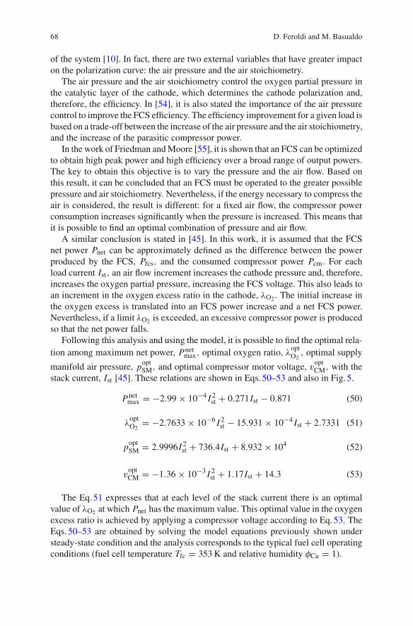
A similar conclusion is stated in [45]. In this work, it is assumed that the FCSnet power Pnet can be approximately defined as the difference between the powerproduced by the FCS, Pfcs, and the consumed compressor power Pcm. For eachload current Ist, an air flow increment increases the cathode pressure and, therefore,increases the oxygen partial pressure, increasing the FCS voltage. This also leads toan increment in the oxygen excess ratio in the cathode, λO2 . The initial increase inthe oxygen excess is translated into an FCS power increase and a net FCS power.Nevertheless, if a limit λO2 is exceeded, an excessive compressor power is producedso that the net power falls.
Following this analysis and using the model, it is possible to find the optimal rela-tion among maximum net power, Pnet
max, optimal oxygen ratio, λoptO2
, optimal supply
manifold air pressure, poptSM, and optimal compressor motor voltage, v
optCM, with the
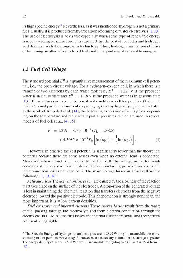
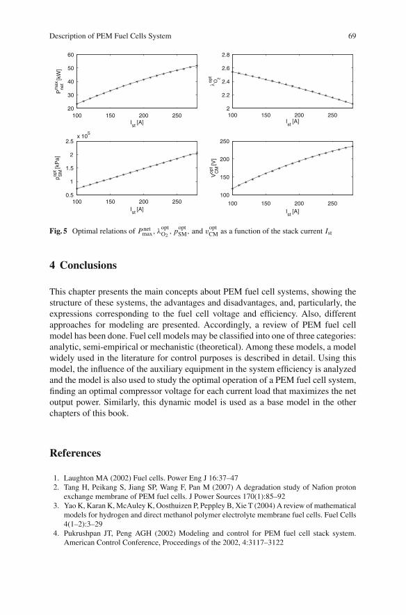
stack current, Ist [45]. These relations are shown in Eqs. 50–53 and also in Fig. 5.
Pnetmax = −2.99 × 10⁻⁴ I 2
st + 0.271Ist − 0.871 (50)
λoptO2
= −2.7633 × 10⁻⁶ I 2st − 15.931 × 10⁻⁴ Ist + 2.7331 (51)
poptSM = 2.9996I 2
st + 736.4Ist + 8.932 × 10⁴ (52)
voptCM = −1.36 × 10⁻³ I 2
st + 1.17Ist + 14.3 (53)
The Eq. 51 expresses that at each level of the stack current there is an optimalvalue of λO2 at which Pnet has the maximum value. This optimal value in the oxygenexcess ratio is achieved by applying a compressor voltage according to Eq. 53. TheEqs. 50–53 are obtained by solving the model equations previously shown understeady-state condition and the analysis corresponds to the typical fuel cell operatingconditions (fuel cell temperature Tfc = 353 K and relative humidity φCa = 1).
Description of PEM Fuel Cells System 69
100 150 200 25020
30
40
50
60
Ist
[A]
Pm
axne
t [k
W]
100 150 200 2502
2.2
2.4
2.6
2.8
Ist
[A]
λopt
O2
100 150 200 2500.5
1
1.5
2
2.5x 10
5
Ist
[A]
popt
SM
[kP
a]
100 150 200 250
100
150
200
250
Ist
[A]V
opt
CM
[V]
Fig. 5 Optimal relations of Pnetmax, λ
optO2
, poptSM, and v
optCM as a function of the stack current Ist
4 Conclusions
This chapter presents the main concepts about PEM fuel cell systems, showing thestructure of these systems, the advantages and disadvantages, and, particularly, theexpressions corresponding to the fuel cell voltage and efficiency. Also, differentapproaches for modeling are presented. Accordingly, a review of PEM fuel cellmodel has been done. Fuel cell models may be classified into one of three categories:analytic, semi-empirical or mechanistic (theoretical). Among these models, a modelwidely used in the literature for control purposes is described in detail. Using thismodel, the influence of the auxiliary equipment in the system efficiency is analyzedand the model is also used to study the optimal operation of a PEM fuel cell system,finding an optimal compressor voltage for each current load that maximizes the netoutput power. Similarly, this dynamic model is used as a base model in the otherchapters of this book.
References
1. Laughton MA (2002) Fuel cells. Power Eng J 16:37–472. Tang H, Peikang S, Jiang SP, Wang F, Pan M (2007) A degradation study of Nafion proton
exchange membrane of PEM fuel cells. J Power Sources 170(1):85–923. Yao K, Karan K, McAuley K, Oosthuizen P, Peppley B, Xie T (2004) A review of mathematical
models for hydrogen and direct methanol polymer electrolyte membrane fuel cells. Fuel Cells4(1–2):3–29
4. Pukrushpan JT, Peng AGH (2002) Modeling and control for PEM fuel cell stack system.American Control Conference, Proceedings of the 2002, 4:3117–3122

70 D. Feroldi and M. Basualdo
5. D’Arco S, Ianuzzi D, Pagano M, Tricoli P (2005) Design criteria optimizing the use of fuel cellsource in electric power system. In: Proceedings of the 16th IFAC World Congress, Prague
6. Zhang J, Xie Z, Zhang J, Tang Y, Song C, Navessin T, Shi Z, Song D, Wang H, Wilkinson DP,Liu Z-S, Holdcroft S (2006) High temperature pem fuel cells. J Power Sources 160(2):872–891
7. Carrette L, Friedrich K, Stimming U (2001) Fuel cells-fundamentals and applications. FuelCells 1(1):5–39
8. Rajashekara K (2000) Propulsion system strategies for fuel cell vehicles. Fuel Cell Technol forVehicles 1:179–187
9. Jeong K, Oh B (2002) Fuel economic and life-cycle cost analysis of a fuel cell hybrid vehicle.J Power Sources 105:58–65
10. Friedman D, Moore R (1998) PEM fuel cell system optimization. In: Proc Electrochem Soc27:407–423
11. EG & G Technical Services, Inc. Science Applications International Corporation (2002) IN:U.S. Department of Energy, Fuel Cell Handbook, 6th edition, Morgantown, West Virginia,USA
12. Flipsen S (2006) Power sources compared: the ultimate truth? J Power Sources 162:927–93413. Larminie J, Dicks A (2003) Fuel Cell Systems Explained, 2nd edn Wiley, New York, USA14. Amphlett J, Mann R, Peppley B, Roberge P, Rodrigues A (1996) A model predicting transient
responses of proton exchange membrane fuel cells. J Power Sources 61:183–18815. Correa J, Farret F, Canha L, Simoes M (2004) An electrochemical-based fuel-cell model suitable
for electrical engineering automation approach. Ind Electron, IEEE Trans on 51(5):1103–111216. Barbir F (2005) PEM fuel cells: theory and practice. Elsevier, Burlington, MA, USA17. Bossel U (2003) Well-to-wheel studies, heating values, and the energy conservation principle.
IN:Ulf Bossel (ed) European Fuel Cell Forum, October 2003, Oberrohrdorf, Switzerland 1:1–518. Pukrushpan J (2003) Modelling and control of fuel cell systems and fuel processors. PhD
thesis, University of Michigan, Ann Arbor, Michigan, USA. http://www-personal.umich.edu/∼annastef/FuelCellPdf/pukrushpan_thesis.pdf
19. Wipke K, Cuddy M, Burch S (1999) Advisor 2.1: a user-friendly advanced powertrain simula-tion using a combined backward/forward approach. IEEE Trans on Vehicular Technol 48:1751–1761
20. Markel T, Brooker A, Hendricks T, Johnson V, Kelly K, Kramer B, O’Keefe M, Sprik S, Wipke K(2002) Advisor: a system analysis tool for advanced vehicle modeling. J Power Sources110:255–266
21. Kim J, Lee SM, Srinivasan S, Chamberlin CE (1995) Modeling of proton exchange membranefuel cell performance with an empirical equation. J Electrochem Soc 142:2670
22. Squadrito G, Maggio G, Passalacqua E, Lufrano F, Patti A (1999) An empirical equation forpolymer electrolyte fuel cell (PEFC) behaviour. J Appl Electrochem 29(12):1449–1455
23. Cheddie D, Munroe N (2005) Review and comparison of approaches to proton exchangemembrane fuel cell modeling. J Power Sources 147(1–2):72–84
24. Bernardi DM, Verbrugge MW (1991) Mathematical model of a gas diffusion electrode bondedto a polymer electrolyte. AIChE J 37(8):1151–1163
25. Bernardi DM, Verbrugge MW (1992) A Mathematical model of the solid-polymer-electrolytefuel cell. J Electrochem Soc 139:2477
26. Springer TE, Zawodzinski TA, Gottesfeld S (1991) Polymer electrolyte fuel cell model.J Electrochem Soc 138(8):2334–2342
27. He W, Yi JS, Van Nguyen T (2000) Two-phase flow model of the cathode of PEM fuel cellsusing interdigitated flow fields. AIChE J 46(10):2053–2064
28. Natarajan D, Van Nguyen T (2001) A two-dimensional, two-phase, multicomponent, tran-sient model for the cathode of a proton exchange membrane fuel cell using conventional gasdistributors. J Electrochem Soc 148:A1324
29. Nguyen TV, White RE (1993) A water and heat management model for proton-exchange-membrane fuel cells. J Electrochem Soc 140:2178
Description of PEM Fuel Cells System 71
30. Wang ZH, Wang CY, Chen KS (2001) Two-phase flow and transport in the air cathode of protonexchange membrane fuel cells. J Power Sources 94(1):40–50
31. Nguyen PT, Berning T, Djilali N (2004) Computational model of a PEM fuel cell with serpentinegas flow channels. J Power Sources 130(1–2):149–157
32. Natarajan D, Van Nguyen T (2003) Three-dimensional effects of liquid water flooding in thecathode of a PEM fuel cell. J Power Sources 115(1):66–80
33. Bernardi DM (1990) Water-balance calculations for solid-polymer-electrolyte fuel cells. J Elec-trochem Soc 137:3344
34. Fuller TF, Newman J (1993) Water and thermal management in solid-polymer-electrolyte fuelcells. J Electrochem Soc 140:1218
35. Wohr M, Bolwin K, Schnurnberger W, Fischer M, Neubrand W, Eigenberger G (1998) Dynamicmodelling and simulation of a polymer membrane fuel cell including mass transport limitation.Int J Hydrogen Energy 23(3):213–218
36. Barsoukov En, Macdonald JR (2005) Impedance spectroscopy: theory, experiment, and appli-cations. Wiley, Hoboken, New Jersey, USA
37. Andreaus B, McEvoy AJ, Scherer GG (2002) Analysis of performance losses in polymerelectrolyte fuel cells at high current densities by impedance spectroscopy. Electrochimica Acta47(13–14):2223–2229
38. Ciureanu M, Mikhailenko SD, Kaliaguine S (2003) PEM fuel cells as membrane reactors:kinetic analysis by impedance spectroscopy. Catal Today 82(1–4):195–206
39. Macdonald DD (2006) Reflections on the history of electrochemical impedance spectroscopy.Electrochimica Acta 51(8–9):1376–1388
40. Primucci M, Ferrer L, Serra M, Riera J (2008) Characterisation of fuel cell state using Elec-trochemical Impedance Spectroscopy analysis. Simposium Ibérico de Hidrógeno, Pilas deCombustible y Baterías Avanzadas (HYCELTEC)
41. Alejandro J, Real D, Arce A, Bordons C (2007) Development and experimental validation ofa pem fuel cell dynamic model. J Power Sources 173(1):310–324
42. Pathapati PR, Xue X, Tang J (2005) A new dynamic model for predicting transient phenomenain a pem fuel cell system. Renew Energy 30(1):1–22
43. El-Sharkh M, Rahman A, Alam M, Byrne P, Sakla A, Thomas T (2004) A dynamic modelfor a stand-alone PEM fuel cell power plant for residential applications. J Power Sources138:199–204
44. An improved dynamic voltage model of pem fuel cell stack (2010) Int J Hydrogen Energy35(20):11154–11160 Hyceltec 2009 Conference
45. Grujicic M, Chittajallu KM, Law EH, Pukrushpan JT (2004) Model-based control strategiesin the dynamic interaction of air supply and fuel cell. Proc Inst Mech Eng, Part A: J PowerEnergy 218(7):487–499
46. Vahidi A, Peng A (2004) Model predictive control for starvation prevention in a hybrid fuelcell system. Am Control Conf, Proc 2004 1:834–839
47. Varigonda S, Pukrushpan JT, Stefanopoulou AG (2003) American Institute of Chemical Engi-neers. Challenges in fuel cell power plant control: the role of system level dynamic models.Am Inst Chem Eng 1:101–110
48. Gelfi S, Stefanopoulou AG, Pukrushpan JT, Huei Peng (2003) Dynamics of low-pressure andhigh-pressure fuel cell air supply systems. In: Am Control Conf, 2003. Proceedings of the 20033:2049–2054
49. Caux S, Lachaize J, Fadel M, Shott P, Nicod L (2005) Energy management of fuel cell systemand supercaps elements. In: Proceedings of the 16th IFAC World Congress, Prague
50. Serra M, Aguado J, Ansade X, Riera J (2005) Controllability analysis of decentralized linearcontrollers for polymeric fuel cells. J Power Sources 151:93–102
51. Feroldi D, Serra M, Riera J (2007) Performance improvement of a pemfc system controllingthe cathode outlet air flow. J Power Sources 169(1):205–212
52. Zenith F, Skogestad S (2007) Control of fuel cell power output. J Process Control 17(4):333–347

72 D. Feroldi and M. Basualdo
53. Ceraolo M, Miulli C, Pozio A (2003) Modelling static and dynamic behaviour of protonexchange membrane fuel cells on the basis of electro-chemical description. J Power Sources113(1):131–144
54. Yang W, Bates B, Fletcher N, Pow R (1998) Control challenges and methodologies in fuel cellvehicles development. Fuel Cell Technol for Vehicles 1:249–256
55. Friedman D (1999) Maximizing direct-hydrogen PEM fuel cell vehicle efficiency-is hybridiza-tion necessary? SAE Int 1:265–272

http://www.springer.com/978-1-84996-183-7
Related Documents