303-01C-1 303-01C-1 Engine — Cobra 4.6L (4V) Induction System DESCRIPTION AND OPERATION Engine The sequential multiport fuel injection (SFI) provides the fuel/air mixture needed for combustion WARNING: Do not operate the engine in the cylinders. The eight solenoid-operated fuel with the hood open until the fan blade has been injectors: first examined for possible cracks and separation. • are mounted in the lower intake manifold. The 4.6L (4V) (281 CID) Cobra engine is a V-8 with the following features: • meter fuel into the air intake stream in accordance with engine demand. • intercooled supercharger • are positioned so that their tips direct fuel just • dual overhead camshafts ahead of the engine intake valves. • four valves per cylinder • are connected in series with the fuel pressure • sequential multiport fuel injection (SFI) sensor. • an aluminum intake manifold • supply fuel from the fuel tank with a fuel pump mounted in the fuel tank. • aluminum cylinder heads A constant fuel pressure drop is maintained across • a cast aluminum, 90-degree V- cylinder block the fuel injectors by the fuel pressure sensor. The • individually chain-driven camshafts with a fuel pressure sensor: hydraulic timing chain tensioner on each timing chain • is positioned upstream from the fuel injectors on the fuel injection supply manifold. • the electronic ignition system with eight ignition coils Valve Train Identification The valve train operates as follows: Always refer to these labels when replacement parts • ball-tip hydraulic lash adjusters provide automatic are necessary or when checking engine calibrations. lash adjustment. The engine parts often differ within a CID family. • roller followers ride on the camshaft lobes, Verification of the identification codes will ensure transferring the up-and-down motion of the that the correct parts are obtained. These codes camshafts to the valves in the cylinder heads. contain all the pertinent information relating to the dates, optional equipment and revisions. The Ford Positive Crankcase Ventilation System Master Parts Catalog contains a complete listing of All engines are equipped with a closed-type positive the codes and their application. crankcase ventilation system recycling the crankcase vapors to the upper intake manifold. Code Information The engine code information label, located on the Lubrication System side of the valve cover and the front side of the The engine lubrication system operates as follows: valve cover, contains the following: • oil is drawn into the oil pump through the oil • engine build date pump screen cover and tube in the sump of the • engine plant code oil pan. • engine code • oil is pumped through the oil bypass filter on the left front side of the cylinder block. Exhaust Emission Control System • oil enters the main oil gallery where it is Operation and necessary maintenance of the exhaust distributed to the crankshaft main journals and to emission control devices used on this engine is both cylinder heads. covered in the Powertrain Control/Emissions Diagnosis (PC/ED) manual. Copyright 2002, Ford Motor Company Last updated: 6/14/2002 2003 Mustang, 8/2002

Welcome message from author
This document is posted to help you gain knowledge. Please leave a comment to let me know what you think about it! Share it to your friends and learn new things together.
Transcript
303-01C-1 303-01C-1Engine — Cobra 4.6L (4V)
Induction SystemDESCRIPTION AND OPERATION
Engine The sequential multiport fuel injection (SFI)provides the fuel/air mixture needed for combustion
WARNING: Do not operate the engine in the cylinders. The eight solenoid-operated fuelwith the hood open until the fan blade has been injectors:first examined for possible cracks and separation.
• are mounted in the lower intake manifold.The 4.6L (4V) (281 CID) Cobra engine is a V-8with the following features: • meter fuel into the air intake stream in accordance
with engine demand.• intercooled supercharger
• are positioned so that their tips direct fuel just• dual overhead camshafts ahead of the engine intake valves.• four valves per cylinder • are connected in series with the fuel pressure• sequential multiport fuel injection (SFI) sensor.• an aluminum intake manifold • supply fuel from the fuel tank with a fuel pump
mounted in the fuel tank.• aluminum cylinder headsA constant fuel pressure drop is maintained across• a cast aluminum, 90-degree V- cylinder blockthe fuel injectors by the fuel pressure sensor. The• individually chain-driven camshafts with afuel pressure sensor:hydraulic timing chain tensioner on each timing
chain • is positioned upstream from the fuel injectors onthe fuel injection supply manifold.• the electronic ignition system with eight ignition
coils Valve TrainIdentification The valve train operates as follows:
Always refer to these labels when replacement parts • ball-tip hydraulic lash adjusters provide automaticare necessary or when checking engine calibrations. lash adjustment.The engine parts often differ within a CID family.
• roller followers ride on the camshaft lobes,Verification of the identification codes will ensuretransferring the up-and-down motion of thethat the correct parts are obtained. These codescamshafts to the valves in the cylinder heads.contain all the pertinent information relating to the
dates, optional equipment and revisions. The Ford Positive Crankcase Ventilation SystemMaster Parts Catalog contains a complete listing of
All engines are equipped with a closed-type positivethe codes and their application.crankcase ventilation system recycling the crankcasevapors to the upper intake manifold.Code Information
The engine code information label, located on the Lubrication Systemside of the valve cover and the front side of the
The engine lubrication system operates as follows:valve cover, contains the following:• oil is drawn into the oil pump through the oil• engine build date
pump screen cover and tube in the sump of the• engine plant code oil pan.• engine code • oil is pumped through the oil bypass filter on the
left front side of the cylinder block.Exhaust Emission Control System• oil enters the main oil gallery where it isOperation and necessary maintenance of the exhaust
distributed to the crankshaft main journals and toemission control devices used on this engine isboth cylinder heads.covered in the Powertrain Control/Emissions
Diagnosis (PC/ED) manual.
Copyright 2002, Ford Motor CompanyLast updated: 6/14/2002 2003 Mustang, 8/2002
303-01C-2 303-01C-2Engine — Cobra 4.6L (4V)
DESCRIPTION AND OPERATION (Continued)
• From the main journals, the oil is routed through • Oil pump displacement has been selected tocross-drilled passages in the crankshaft to provide adequate volume to ensure correct oillubricate the connecting rod bearings. Controlled pressure both at hot idle and maximum speed.leakage through the crankshaft main bearings and • The relief valve calibration protects the systemconnecting rod bearings is slung radially outward from excessive pressure during high viscosityto cool and lubricate the cylinder walls as well as conditions.the entire connecting rod, piston and piston rings
• The relief valve is designed to provide adequateassembly.connecting rod bearing lubrication under
• The left cylinder head is fed from a drilling into high-temperature and high-speed conditions.the supply passage feeding the main gallery at thefront of the cylinder block. The right cylinder Cooling Systemhead is fed from a drilling into the rear of the The engine cooling system includes the following:main gallery. Main gallery pressure is reduced as
• radiatorit enters the cylinder head galleries through fixedserviceable orifices located at the upper part of • water pumpthe feed passages. It is this reduced pressure in • the electric cooling fan motor and fan blade,the cylinder head galleries which feeds the activated by the variable control modulecamshaft journals, the hydraulic lash adjusters
• the degas bottle, which aids in maintaining theand the primary and secondary timing chaincorrect volume of engine coolanttensioners.
• water thermostat• The camshaft lobe and roller followers arelubricated by splash created through valve train • upper radiator hoseoperation. • lower radiator hose
Oil Pump • heater water hoses
The lubrication system of the 4.6L (4V) engine is Drive Belt Systemdesigned to provide optimum oil flow to critical
The 4.6L (4V) DOHC engine is equipped with acomponents of the engine through its entireserpentine drive belt. To ensure maximum life, aoperating range. The heart of the system is areplacement drive belt should be of the same typepositive displacement internal gear oil pump usingas originally installed.top seal rotors. Generically this design is known as
a gerotor pump, which operates as follows. • The accessories mounted on the front of theengine are belt-driven by the crankshaft.• The oil pump is mounted on the front face of the
cylinder block. • The serpentine drive belt is routed over eachaccessory pulley, driven by the crankshaft pulley• The inner rotor is piloted on the crankshaft postbolted to the crankshaft.and is driven through flats on the crankshaft.
For service procedures, including tensioning, refer to• System pressure is limited by an integral,Section 303-05.internally-vented relief valve which directs the
bypassed oil back to the inlet side of the oilpump.
2003 Mustang, 8/2002
303-01C-3 303-01C-3Engine — Cobra 4.6L (4V)
DESCRIPTION AND OPERATION (Continued)
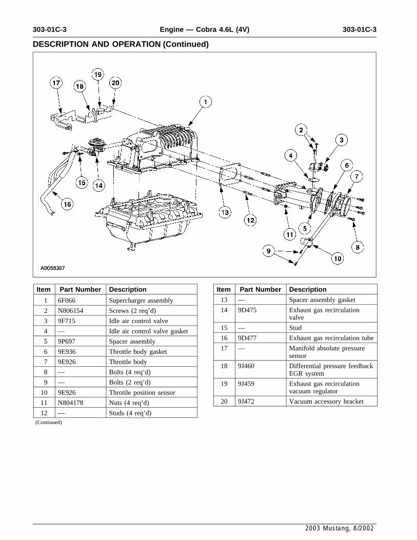
Item Part Number Description Item Part Number Description
13 — Spacer assembly gasket1 6F066 Supercharger assembly
14 9D475 Exhaust gas recirculation2 N806154 Screws (2 req’d)valve3 9F715 Idle air control valve
15 — Stud4 — Idle air control valve gasket16 9D477 Exhaust gas recirculation tube5 9P697 Spacer assembly17 — Manifold absolute pressure6 9E936 Throttle body gasket
sensor7 9E926 Throttle body
18 9J460 Differential pressure feedback8 — Bolts (4 req’d) EGR system9 — Bolts (2 req’d) 19 9J459 Exhaust gas recirculation
vacuum regulator10 9E926 Throttle position sensor20 9J472 Vacuum accessory bracket11 N804178 Nuts (4 req’d)
12 — Studs (4 req’d)(Continued)
2003 Mustang, 8/2002
303-01C-4 303-01C-4Engine — Cobra 4.6L (4V)
DESCRIPTION AND OPERATION (Continued)
2003 Mustang, 8/2002
303-01C-5 303-01C-5Engine — Cobra 4.6L (4V)
DESCRIPTION AND OPERATION (Continued)
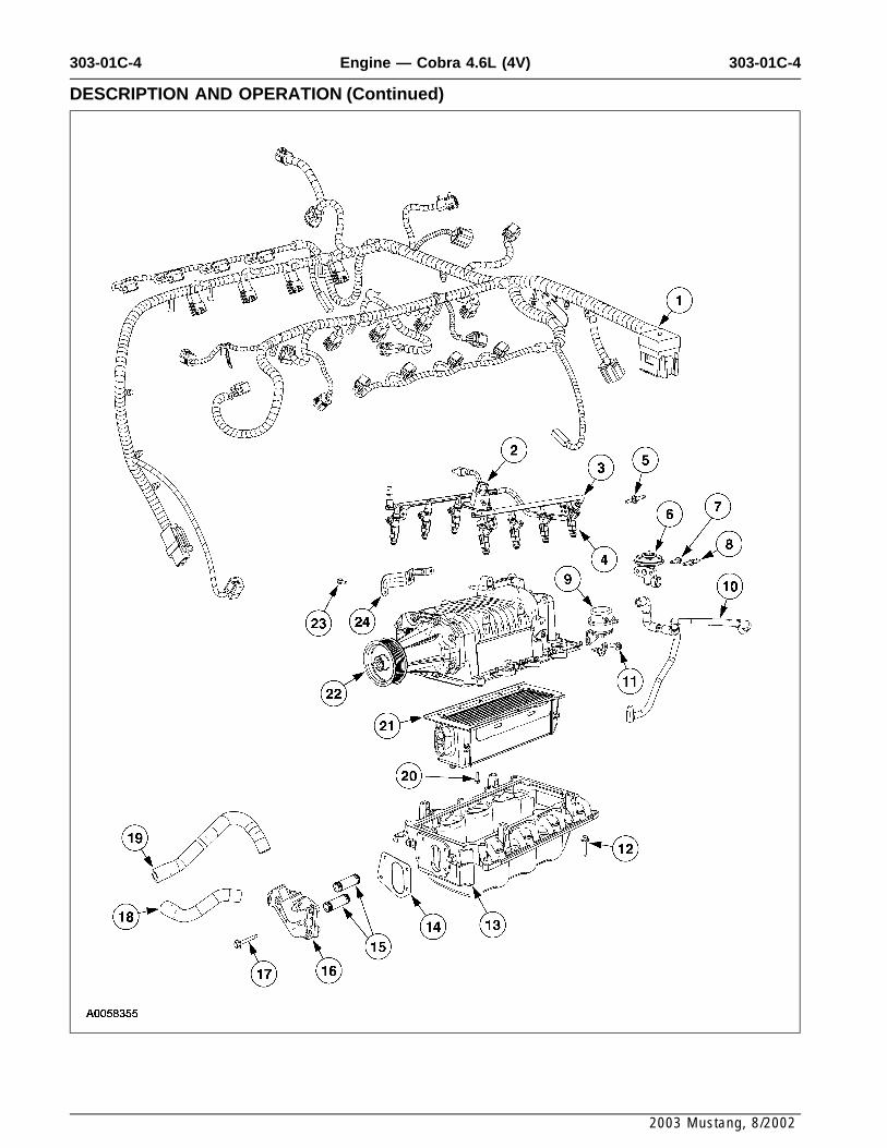
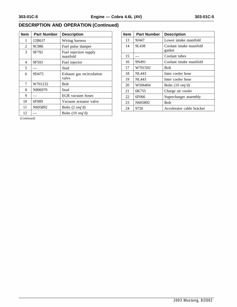
Item Part Number Description Item Part Number Description
13 9J447 Lower intake manifold1 12B637 Wiring harness
14 9L438 Coolant intake manifold2 9C986 Fuel pulse dampergasket3 9F792 Fuel injection supply
15 — Coolant tubesmanifold
16 9N491 Coolant intake manifold4 9F593 Fuel injector
17 W701592 Bolt5 — Stud
18 NL443 Inter cooler hose6 9D475 Exhaust gas recirculationvalve 19 NL443 Inter cooler hose
7 W701232 Bolt 20 W506404 Bolts (10 req’d)8 N806979 Stud 21 6K755 Charge air cooler9 — EGR vacuum hoses 22 6F066 Supercharger assembly
10 6F089 Vacuum actuator valve 23 N605892 Bolt11 N605892 Bolts (2 req’d) 24 9726 Accelerator cable bracket12 — Bolts (10 req’d)
(Continued)
2003 Mustang, 8/2002
303-01C-6 303-01C-6Engine — Cobra 4.6L (4V)
DESCRIPTION AND OPERATION (Continued)
2003 Mustang, 8/2002
303-01C-7 303-01C-7Engine — Cobra 4.6L (4V)
DESCRIPTION AND OPERATION (Continued)
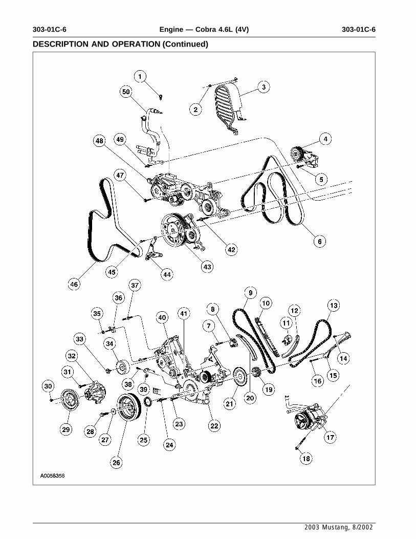
Item Part Number Description Item Part Number Description
27 N806165 Washer1 N605904 Bolt
28 W701512 Stud2 N620480 Nut
29 8A528 Water pump pulley3 6A946 Cover
30 N806282 Bolts (4 req’d)4 17K814 Alternator bracket assembly
31 N806177 Bolts (4 req’d)5 N811268 Bolts (2 req’d)
32 8501 Water pump6 8620 Accessory drive belt
33 N808102 Bolt7 N606543 Bolt (4 req’d)
34 19A216 Belt idler pulley8 6L266 Timing chain tensioner
35 N804178 Nut9 6268 Timing chain (2 req’d)
36 N806300 Harness support bracket10 6M256 Timing chain guide
37 N806300 Stud11 6L266 Timing chain tensioner
38 N806155 Bolt12 6L253 Timing chain tensioner arm
39 6C315 Crankshaft position sensor13 6268 Timing chain (2 req’d)
40 N806155 Bolt14 N804958 Bolt (2 req’d)
41 6B288 Camshaft position sensor15 6B274 Timing chain guide
42 N808920 Bolts (3 req’d)16 N606527 Bolt
43 6C254 Crankshaft extension support17 19D269 A/C compressorpulley18 N806184 Bolts (3 req’d)
44 10153 Lower support bracket19 6306 Crankshaft sprocket45 N605909 Bolts (2 req’d)20 6L253 Timing chain tensioner arm46 8620 Accessory drive belt21 12A227 Ignition pulse ring47 N811268 Bolt22 6C086 Engine front cover48 8B603 Belt idler bracket support23 N806177 Bolts (8 req’d)49 N808198 Stud24 N806300 Studs (5 req’d)50 9N491 Hose and tube assembly25 6700 Crankshaft front seal
26 6316 Crankshaft pulley(Continued)
2003 Mustang, 8/2002
303-01C-8 303-01C-8Engine — Cobra 4.6L (4V)
DESCRIPTION AND OPERATION (Continued)
2003 Mustang, 8/2002
303-01C-9 303-01C-9Engine — Cobra 4.6L (4V)
DESCRIPTION AND OPERATION (Continued)
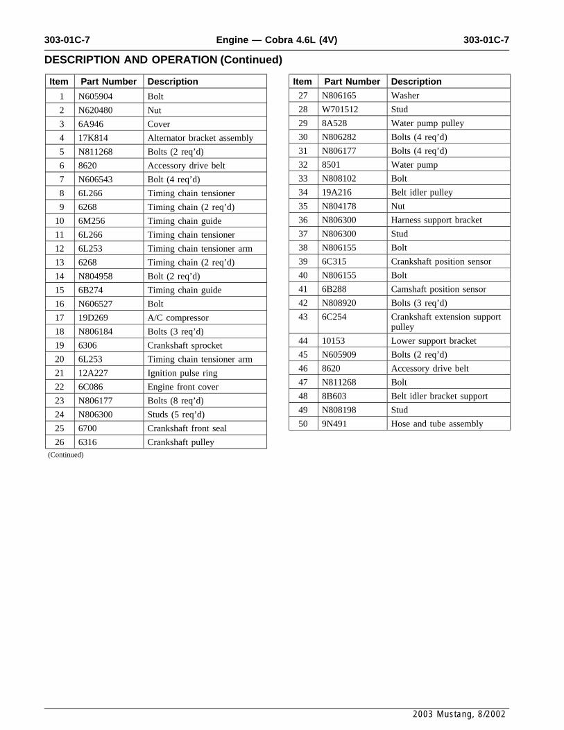
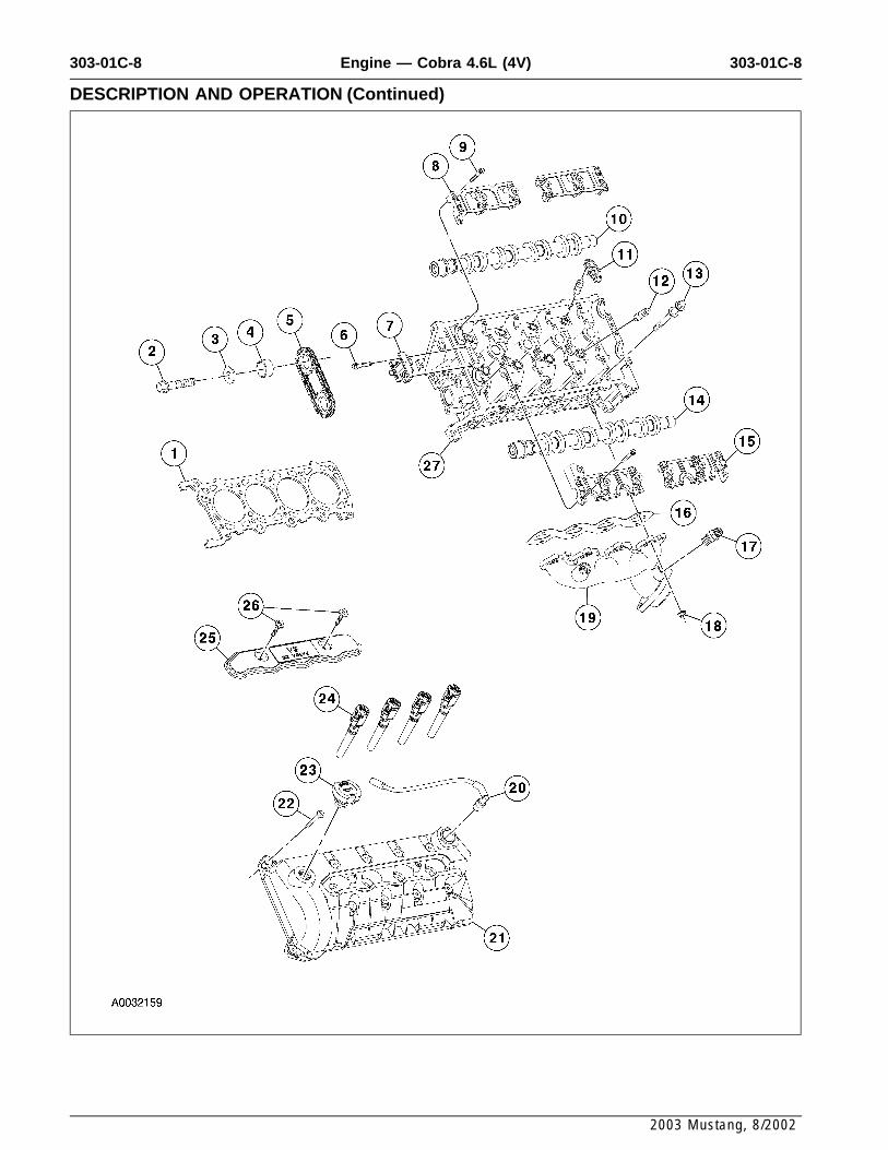
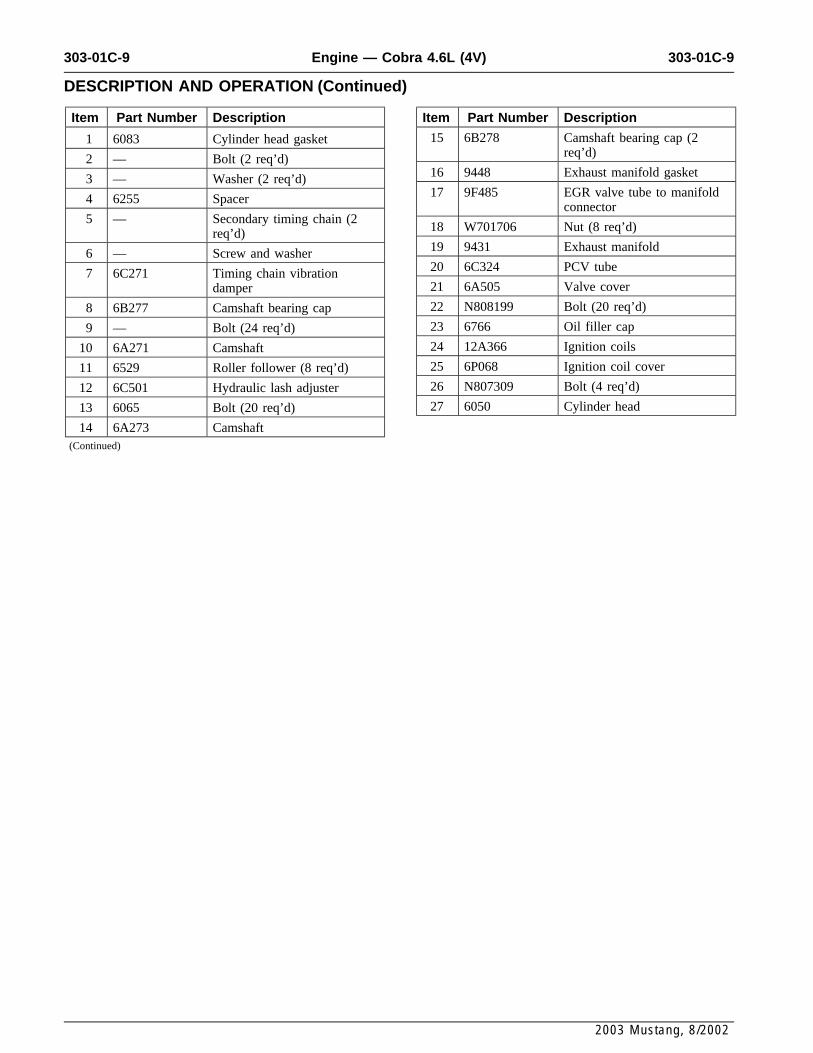
Item Part Number Description Item Part Number Description
15 6B278 Camshaft bearing cap (21 6083 Cylinder head gasketreq’d)2 — Bolt (2 req’d)
16 9448 Exhaust manifold gasket3 — Washer (2 req’d)17 9F485 EGR valve tube to manifold4 6255 Spacer
connector5 — Secondary timing chain (2
18 W701706 Nut (8 req’d)req’d)19 9431 Exhaust manifold6 — Screw and washer20 6C324 PCV tube7 6C271 Timing chain vibration21 6A505 Valve coverdamper
22 N808199 Bolt (20 req’d)8 6B277 Camshaft bearing cap
23 6766 Oil filler cap9 — Bolt (24 req’d)
24 12A366 Ignition coils10 6A271 Camshaft
25 6P068 Ignition coil cover11 6529 Roller follower (8 req’d)
26 N807309 Bolt (4 req’d)12 6C501 Hydraulic lash adjuster
27 6050 Cylinder head13 6065 Bolt (20 req’d)
14 6A273 Camshaft(Continued)
2003 Mustang, 8/2002
303-01C-10 303-01C-10Engine — Cobra 4.6L (4V)
DESCRIPTION AND OPERATION (Continued)
2003 Mustang, 8/2002
303-01C-11 303-01C-11Engine — Cobra 4.6L (4V)
DESCRIPTION AND OPERATION (Continued)
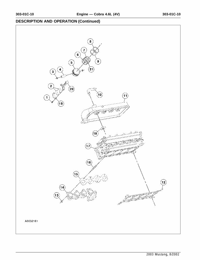
Item Part Number Description Item Part Number Description
11 6582 Valve cover1 6214 Bolt (2 req’d)
12 6051 Cylinder head gasket2 6211 Connecting rod bearing (16req’d) 13 W701706 Nut (8 req’d)
3 6140 Piston pin retainer (16 req’d) 14 9430 Exhaust manifold4 6135 Piston pin (8 req’d) 15 9448 Exhaust manifold gasket5 6110 Piston (8 req’d) 16 W701681 Stud (8 req’d)6 6159 Piston ring (8 req’d) 17 6049 Cylinder head7 6159 Piston ring (8 req’d) (part of 18 6C527 Spark plug gasket (8 req’d)
6100)19 6200 Connecting rod (8 req’d)
8 6150 Piston ring (8 req’d) (part of20 6200 Connecting rod (8 req’d)6100)21 6161 Piston ring (8 req’d)9 6152 Piston ring (8 req’d)
10 6758 Crankcase vent tube andconnector
(Continued)
2003 Mustang, 8/2002
303-01C-12 303-01C-12Engine — Cobra 4.6L (4V)
DESCRIPTION AND OPERATION (Continued)
2003 Mustang, 8/2002
303-01C-13 303-01C-13Engine — Cobra 4.6L (4V)
DESCRIPTION AND OPERATION (Continued)
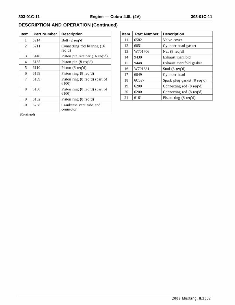
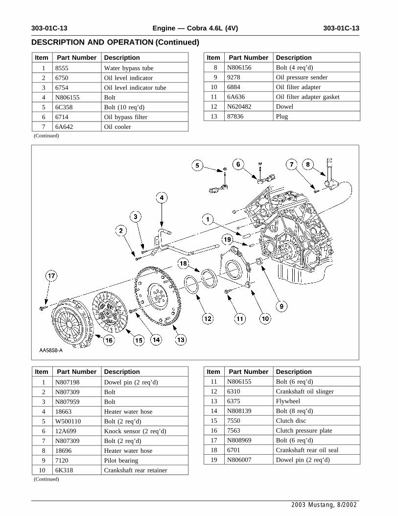
Item Part Number Description Item Part Number Description
8 N806156 Bolt (4 req’d)1 8555 Water bypass tube
9 9278 Oil pressure sender2 6750 Oil level indicator
10 6884 Oil filter adapter3 6754 Oil level indicator tube
11 6A636 Oil filter adapter gasket4 N806155 Bolt
12 N620482 Dowel5 6C358 Bolt (10 req’d)
13 87836 Plug6 6714 Oil bypass filter
7 6A642 Oil cooler(Continued)
Item Part Number Description Item Part Number Description
11 N806155 Bolt (6 req’d)1 N807198 Dowel pin (2 req’d)
12 6310 Crankshaft oil slinger2 N807309 Bolt
13 6375 Flywheel3 N807959 Bolt
14 N808139 Bolt (8 req’d)4 18663 Heater water hose
15 7550 Clutch disc5 W500110 Bolt (2 req’d)
16 7563 Clutch pressure plate6 12A699 Knock sensor (2 req’d)
17 N808969 Bolt (6 req’d)7 N807309 Bolt (2 req’d)
18 6701 Crankshaft rear oil seal8 18696 Heater water hose
19 N806007 Dowel pin (2 req’d)9 7120 Pilot bearing
10 6K318 Crankshaft rear retainer(Continued)
2003 Mustang, 8/2002
303-01C-14 303-01C-14Engine — Cobra 4.6L (4V)
DESCRIPTION AND OPERATION (Continued)
2003 Mustang, 8/2002
303-01C-15 303-01C-15Engine — Cobra 4.6L (4V)
DESCRIPTION AND OPERATION (Continued)
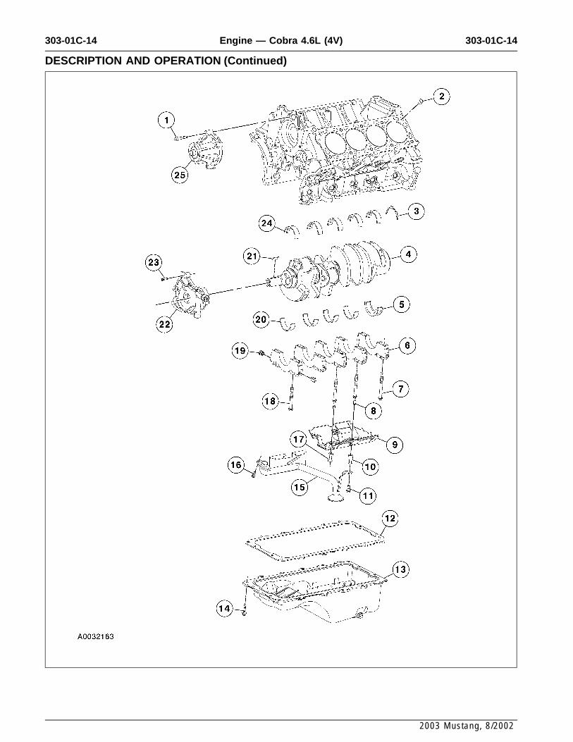
Item Part Number Description Item Part Number Description
15 6622 Oil pump screen pickup and1 N806177 Bolt (4 req’d)tube2 N806459 Dowel (4 req’d)
16 N806155 Bolt (2 req’d)3 6A341 Thrust washer17 N811280 Spacer (3 req’d)4 6303 Crankshaft18 6345 Bolt (6 req’d)5 6A339 Thrust bearing19 6C360 Main bearing cap adjusting6 6325 Main bearing cap (5 req’d)
screw (10 req’d)7 6345 Bolt (10 req’d)
20 6A338 Crankshaft main bearing (48 6K258 Stud (4 req’d) req’d)9 6687 Oil pan baffle 21 N806201 Woodruff key
10 N806180 Spacer 22 6621 Oil pump11 N605904 Bolt 23 N806183 Bolt (4 req’d)12 6710 Oil pan gasket 24 6333 Crankshaft main bearing13 6675 Oil pan 25 8501 Water pump14 W701240 Bolt (16 req’d)
(Continued)
2003 Mustang, 8/2002
Related Documents


